Embed Size (px)
Citation preview
Indian Society for Non-Destructive Testing Hyderabad Chapter
Proc. National Seminar on Non-Destructive Evaluation Dec. 7 - 9, 2006, Hyderabad
NDE-2006
In-Service Inspection - A Vital Role in Monitoring & Health Assessment of
Nuclear Pressure Vessels, Piping & Components at Tarapur Atomic Power
Station-1&2, NPCIL
A. Ramu1, M.D. Mangsulikar
2, M. Bandyopadhyay
3, M. Mohan Babu
4,
K.R. Anilkumar1, B.L. Sharma
1, S. Bhattacharjee
1 and U. Ramamurty
1
1Tarapur Atomic Power Station 1 & 2, NPCIL, PO: TAPP, Dist. Thane, Mumbai-401 504 2Atomic Fuels Division, BARC, Mumbai-400 085
3 Division of Remote Handling and Robotics, BARC, Mumbai-400 085 4Quality Assurance(ISI Section), NPCI, Mumbai-400 085
e-mail: [email protected]@rediffmaiI.com
Abstract
Tarapur Atomic Power Station is a twin unit Boiling Water Reactors (BWRs) built in
1960's and presently operating at 160MWe. TAPS has completed 36 years of
successful commercial operation and is continuing to provide safe, economic and
reliable power supply. The design life of Tarapur nuclear reactors is 40 Effective Full
Power Years (EFPY). So far TAPS has completed about 20EFPY for each reactor. In
order to estimate the healthiness of nuclear components, a comprehensive study was
made by the station in consultation with design group of NPCIL. In-Service
Inspection (ISI) substantially enhances confidence in component performance.
Consolidated inspection early in service life provides greater assurance of
component's integrity. Periodic in service inspection provides vital information in the
form of Haw characterization for assessment of structural integrity. This paper
describes various degradation mechanisms (SCC, IGSCC, TGSCC, EC, F AC etc.,) identified for critical components, their method of detection, methodologies followed
for In-Service inspection and developmental activities to assess the integrity of
nuclear reactor vessels, piping & components for continued service. Also a
comprehensive examination carried out on Structures, Systems and Components
(SSCs) as part of plant ageing management programme is also discussed.
Keywords: EFPY, IGSCC, TGSCC, Fatigue, Erosion-corrosion, Flow assisted corrosion
1. Introduction
Tarapur Atomic Power Station -1&2
consists of Boiling Water TAPS has
completed 36 years of commercial operation
till date and still giving excellent
performance with a station capacity factor
close to 90%. The rated capacity of these
units is 210Mwe, however subsequent to
isolation of Secondary Steam Generators
(SSGs), both the units are operating at its re-
rated capacity of 160 MWe, since 1985. The
performance of both units improved over
the years.
Managing the effects of Structures,
Systems & Components (SSCs) ageing
requires effective implementation of ageing
management programme. This includes
timely detection & mitigation of
degradation mechanisms of SSCs so that
their integrity and capability is ensured
A. Ramu et al.
NDE-2006 172
throughout the plant life. The aim of ageing
management programme of SSCs is to
identify the components affected by various
degradation mechanisms and assess their
condition vis-a-vis its integrity for
continued service life.
TAPS has three and half decades of
experience in monitoring the condition of
various SSCs through systematic inservice
Inspection (ISI) Programme. TAPS has also
developed various interim repair
methodologies outlined by USNRC and in
various applicable codes & standards. This
article covers briefly about the methodology
followed to assess and qualify SSCs for
continued service of TAPS units through in-
service Inspection.
2. Inspection philosophy
In-Service Inspection substantially
enhances confidence in component
performance. Concentrating inspection early
in service life provides even greater
assurance of component's integrity. Periodic
in-service inspection provides vital
information in the form of flaw
characterization for assessment of structural
integrity. The intent of ISI is to detect any
discontinuities or flaws in the areas of
interest, which affects the functional
requirement of the components for
continued service.
There are several systems connected to
reactor pressure vessel and forms primary
system pressure boundary to meet the
functional requirements. Based on this,
system classification has been made. The
systems have been broadly classified as
Class-I, 2 and 3. Functional requirements
and safety significance of various
components have also been considered in
classification. Safety class-l is most
important and safety classes 2 and 3 are
successively of lesser importance. The
class-l system components with integral
attachments consist of Reactor Coolant
Pressure (RCP) boundary and those
components whose failure could cause loss
of coolant from the reactor core and which
cannot be isolated from the core. All the
system components connected to Reactor
Pressure Vessel (RPV) were designed and
fabricated as per ASME B&PV Code, Sub
Section-III NB, Division 1.
The class-I components include those
that encompass the reactor coolant system
and portion of systems connected thereto,
located within the confines of the primary
containment structure. This includes the
outermost isolation valves in the system
piping that penetrates the containment. The
general philosophy for this class is to
examine all welds before plant operation
commences, which is called as Pre-Service
Inspection (PSI). The purpose of In-Service
Inspection (IS!) is: (a) to detect the flaws
which were within acceptable range during
construction but could have become un-
acceptable in course of operation and (b) to
detect service-induced defects like
Intergranular Stress Corrosion Cracking
(IGSCC), fatigue, Transgranular Stress
Corrosion Cracking (TGSCC) etc.,. The
following section describes various methods
of inspection methods, repair &
replacements followed at TAPS. The
methodology used to monitor healthiness of
weld joints and piping is also discussed.
Most of the class-l pressure piping
components is having material of
construction either Austenitic Stainless Steel
(SS)-304 or 316. The study report published
in the year 1977[1] by NUREG on Material
selection and processing guide lines for
BWR coolant pressure boundary piping
reported that type 304 and 316 austenitic
stainless steel piping of BWRs are
susceptible to IGSCC. TAPS had taken the
corrective steps based on the
recommendations given there. TAPS
follows AS ME B&PV code Section XI for
in-service inspection of nuclear
components. The jurisdiction of ASME
Code, Section XI begins when the

Monitoring & Health Assessment of Nuclear Pressure Vessels, Piping & Components
NDE-2006 173
component has met the requirement of
ASME code Section-III and Section VIII for
fabrication. The scope of this code includes
in-service inspection of RPV along with
internal core support structure, piping,
pumps, valves, supports and primary system
pressure boundary. The in-service testing of
pumps and valves has also been included in
this code. The technical specification, which
is a station's governing document, describes
the requirements of in-service inspection of
class-I, 2 & 3 system components as per the
station's ISI Manual [2].
The station ISI manual has been prepared
based on guidelines given in ASME Section
XI B&PV code [3], July 1998 edition.
Inspection procedures have been
periodically modified based on the past
experience. The inspection of these
components is possible only during plant
shutdowns i.e., in refueling outages or in
short shutdowns. Hence, a comprehensive
ISI programme ensures the coverage of
component inspection and testing to meet
the requirements specified in the manual.
There are two inspection programs
(Programme-A &B) specified in ASME
Section XI. Once the commercial operation
begins, the intent is to have all the
components inspected once during the first
inspection interval of 10 years. Initially, the
inspection interval was specified as ten
years with a certain percentage of the total
examination covered in the three inspection
periods within this interval. This equi-
spaced examination is referred as Inspection
Programme-B, and an unequal inspection
interval also mentioned in Section-XI, is
called inspection programme-A. TAPS
follows inspection programme-B and so far
three inspection intervals have been
completed.
3. In-service Inspection (ISI) - History
The recommendations mentioned in the
study report [1] were reviewed for
applicability to TAPS in the year 1983 and
prior to this; inspections were carried out
based on SRI (Stress Rule Index) and DMI
(Damage Model Index) criteria. Based on
the SRI and DMI the primary system
pressure boundary weld joints were
inspected on priority. SRI values having
more than 1.0 were subjected to these
examinations because of more susceptibility
to damage mechanisms such as IGSCC [4].
ISI programme has been devised based on
the experience gained from the inspections
during the initial period and technical
information available, as provided by GE &
USNRC reports from time to time. The ISI
manual was developed in mid 80's
conforming to ASME Section XI
requirements and it has been revised based
on latest code revision in July 1998. TAPS
had some SS piping failures related to
IGSCC and TGSCC in the primary system
pressure boundary components.
3.1 Degradation Mechanisms
The austenitic stainless steel piping
welds & HAZs is susceptible to Stress
corrosion cracking. IGSCC, TGSCC and
pitting corrosion are some of those
degradation mechanisms responsible for
primary system piping components, having
austenitic stainless steel as MOC. Some of
SS piping has shown pitting type of
corrosion. The reason could be established
after thorough examination of the affected
areas. These piping are supported with
either fixed or flexible piping supports. The
rigid supports are having carbon steel as
material of construction. Due to this, the
general corrosion products (Oxide flakes)
are in contact with SS surfaces leading to
localized pitting corrosion. Therefore, the
vulnerable areas are inspected during
regular ISI. To over come this problem, SS
shims have been incorporated in-between
the CS support and stainless steel piping.
The degradation mechanism is well
understood from various research reports
and experiments conducted by EPRI in the
specific areas. TAPS had carried out
A. Ramu et al.
NDE-2006 174
detailed study and identified the vulnerable
areas and inspection programmes were
enhanced. The inspection procedures were
modified to detect the deficiencies. Other
than austenitic stainless steel piping, carbon
steel as MOC has been used in primary
feed, condensate, steam extraction and
steam supply system. The degradation
mechanism in these piping is attributed due
to either erosion or Erosion-Corrosion.
The ISI of primary system components is
carried out during refueling outages due to
its in-accessibility while units are in
operation. Hence, the review of the ISI
results is crucial with respect to its adequacy
for continued operation till the next
shutdown. The acceptance criteria followed
as well as the replacement of system piping
is done as per the guidelines of ASME
Section XI and applicable code cases. The
primary system piping is ranging from 1"
NB to 24" diameter and out of these failures
was observed in 1" to 8" NB size piping.
The cause of the failures was analyzed to be
due to IGSCC, as these piping sizes have
unfavorable stress pattern. Fig.! shows the
trend of piping failures subjected to IGSCC.
The mitigation measures were initiated
based on the guidelines available from
various international study reports (5) on
IGSCC from time to time. Remedial
measures are followed scrupulously to
prevent IGSCC; these include replacing the
piping with corrosion resistant material type
316L/316LN grade, Heat Sink Welding
(HSW) and Last Pass Heat Sink Welding
(LPHSW).
Reactor Pressure Vessel internals such as
core support structure (including reactor
core shroud) ECCS spargers & their
attachments etc., are susceptible to IGSCC
and IASCC. The examination of these
components is carried out using under water
radiation resistant cameras. The reactor core
shroud is a core support structure and
showed crack indications in core shroud
welds in overseas BWRs. These indications
were found in visual examination using
qualified inspection systems. The
degradation mechanism is identified to be
due to IGSCC and IASCC in few cases.
4. Inspection and Testing Methods
Inspection Programme-B of ASME
Section-XI includes a 10-year inspection
interval having inspection period (calendar
year) as 3, 7, and 10 calendar years in which
the minimum % of examination has been
specified as 16, 50 & 100. The examination
covered is surface examination i.e. LPT,
volumetric examination i.e., UT and visual
examination (VT-l, VT-2 and VT -3). VT -1
examinations are conducted to detect
discontinuities and imperfections on the
surfaces of components, including such
indications as cracks, wear, corrosion, or
erosion. VT -2 examinations are conducted
to detect evidence of leakage from pressure
retaining components, with or without
leakage collection systems, as required
during the conduct of system pressure test.
VT -3 examinations are conducted to
determine the general mechanical and
structural condition of components and their
supports: and to detect discontinuities and
imperfections, such as loss of integrity at
bolted or welded connections, loose or
missing parts, debris, corrosion, wear, or
erosion. ISI programme has been devised
based on the experience gained from the
failures in initial period and technical
information available as provided by GE &
other USNRC reports from time to time.
The ISI manual was developed in mid 80's
conforming to ASME Section XI
requirements and it has been revised based
on latest code revision in July 1998. The ISI
of primary system components is carried out
during refueling outage due to the
component in-accessibility while unit is in
operation. Hence, the review of the ISI
results is crucial with respect to its adequacy
for continued operation till the next
shutdown period. The examinations carried
out are VT, PT & UT of all the welds/HAZ
and primary system boundary components
Monitoring & Health Assessment of Nuclear Pressure Vessels, Piping & Components
NDE-2006 175
and its integral/external attachments.
Qualified inspection personnel carry out
these examinations based on the approved
NDT procedures.
5. Detection and Monitoring
Visual examination of pressure retaining
boundary has proved to be more useful,
which is carried out during initial system
leakage tests, prior to taking up unit outage
for refueling and also prior to starting up the
units after a refueling outage. This is one of
the mandatory requirements as per ASME
section-XI. Most of the SS piping failures
could be detected during system leak checks
(VT -2). Fig.2 shows the distribution of
failure detection during system leakage
tests, in-service inspection and other
surveillance checks. The SS piping failures
are mostly IGSCC, TGSCC and some are
due to pitting corrosion. Depending upon
the component criticality and isolability,
repair/replacements are done with approved
procedures. Failure analysis and evaluation
of various Class-I, 2&3 system components
is carried out by different agencies such as
Quality Assurance Division (QAD), BARC
and Post Irradiated Examination Division
(PIED), BARC and Division of Remote
Handling & Robotics (DRHR), BARC
which was supportive in devising timely
corrective actions.
The primary system piping is covered
with thermal insulation. Spillages and
leakages of fluids through equipments &
valves and contaminants such as chlorides
may leach from asbestos insulation &
deposit on SS piping surfaces. This results
in chloride-induced (Transgranular) Stress
Corrosion Cracking (TGSCC) [6]. This was
overcome by replacing the affected
insulation with either by less chloride
thermal insulation and/or by replacing
piping insulation with mirror type metallic
reflective insulation/rock wool filled
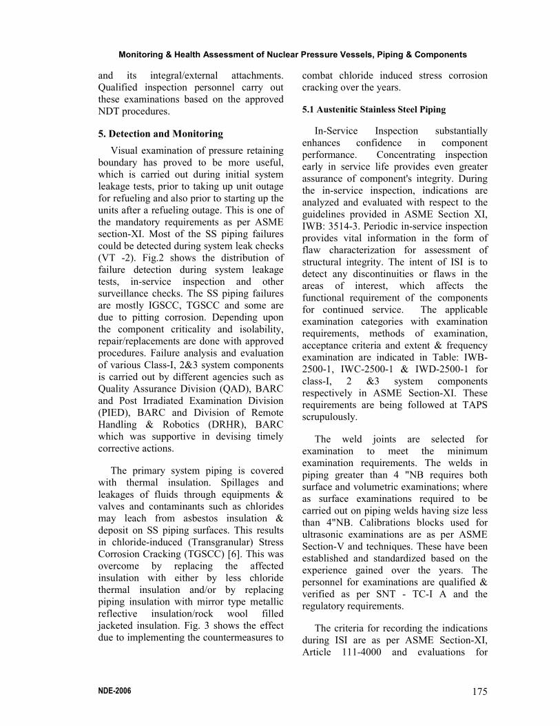
jacketed insulation. Fig. 3 shows the effect
due to implementing the countermeasures to
combat chloride induced stress corrosion
cracking over the years.
5.1 Austenitic Stainless Steel Piping
In-Service Inspection substantially
enhances confidence in component
performance. Concentrating inspection
early in service life provides even greater
assurance of component's integrity. During
the in-service inspection, indications are
analyzed and evaluated with respect to the
guidelines provided in ASME Section XI,
IWB: 3514-3. Periodic in-service inspection
provides vital information in the form of
flaw characterization for assessment of
structural integrity. The intent of ISI is to
detect any discontinuities or flaws in the
areas of interest, which affects the
functional requirement of the components
for continued service. The applicable
examination categories with examination
requirements, methods of examination,
acceptance criteria and extent & frequency
examination are indicated in Table: IWB-
2500-1, IWC-2500-1 & IWD-2500-1 for
class-I, 2 &3 system components
respectively in ASME Section-XI. These
requirements are being followed at TAPS
scrupulously.
The weld joints are selected for
examination to meet the minimum
examination requirements. The welds in
piping greater than 4 "NB requires both
surface and volumetric examinations; where
as surface examinations required to be
carried out on piping welds having size less
than 4"NB. Calibrations blocks used for
ultrasonic examinations are as per ASME
Section-V and techniques. These have been
established and standardized based on the
experience gained over the years. The
personnel for examinations are qualified &
verified as per SNT - TC-I A and the
regulatory requirements.
The criteria for recording the indications
during ISI are as per ASME Section-XI,
Article 111-4000 and evaluations for

A. Ramu et al.
NDE-2006 176
acceptance are as per IWB 3514.3. The
evaluation is based on the aspect ratio. As
per this criterion, the actual circumferential
cracks in welds are usually very long in
relation to its depth: therefore crack growth
in a congruent manner cannot be assumed,
particularly for larger diameter pipes [1].
The growth in the circumferential direction
along the length therefore may be more than
in the depth direction. Specifically, the
growth along the length should be assumed
to increase the aspect ratio (Length to
Depth) by the same factor that the depth is
increased. For ISI the aspect ratio shall not
be more than 0.5. The indications from the
reflectors having the amplitude more than
20% reference level are investigated as per
Section XI and the maximum amplitude;
location and extent of these reflectors are
recorded. The monitoring is being done to
estimate the crack gro\\1h and their
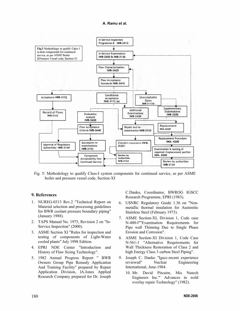
characteristics. Fig.5 gives the general
procedure/flow chart followed to qualify
class-l system components for continued
service.
5.2 Carbon Steel Piping & Fittings
Ultrasonic thickness measurement &
visual examination is the method used to
detect the deficiencies in the areas
vulnerable to corrosion as well as EC. The
high-energy system piping is covered in this
category. Structured in-service inspection
programme exists and detailed out in the
station's ISI manual. The thickness is
monitored and evaluated as per the
applicable code cases, N-480[7] & N-561-1
[8].
5.3 Reactor Core Shroud and RPV Internals
The reactor core shroud is a critical
component of RPV, which supports the core
laterally. Special inspection system were
jointly developed by NPCIL-QA, AFD &
DRHR, BARC were used extensively for
visual examination of accessible welds of
core shroud & core internal components.
Prior to examination, the inspection systems
were qualified in the full-scale mock-up
facilities. Based on the observations in
overseas BWRs, the core shroud welds of
both the reactors were subjected to VT as
well as Ultrasonic testing. As the core
support structure is non-pressure retaining
component and in view of the satisfactory
results obtained during the comprehensive
examinations, presently reactor core shrouds
are being examined by Visual method,
which is as per ASME Section-XI
requirements.
6. Mitigation of Degradation - Measures
6.1 Austenitic Stainless Steel Piping
Wherever repair and replacements of the
components is required as per Section XI
acceptance criteria, its evaluation is done in
two steps. The piping for which isolation is
not possible, it is temporarily repaired by
weld overlay technique/split sleeve
technique, which is accepted by USNRC [9]
[10]. The piping having isolation are
replaced by corrosion resistance material
namely SS-316L or 316LN grade material.
Temporary repair methodology followed
at TAPS was either split sleeve or overlay
method in line with the guidelines provided
by Nutech Technical document [11]. The
overlay design were practiced and proved to
be successful for continued operation for
more than one fuel cycle. During the repair,
the construction code requirements were
met with regard to NDT. There has never
been a pipe severance incidence so far and
the "leak-before-break (LBB)" concepts
remain valid. The affected piping was
replaced subsequently with SS-316L or LN
grade piping with proper procedures. Full
Scale Mock-ups were carried out to qualify
the welding procedures and also to establish
the procedures for reduction of man-rem
consumption during replacement work.
TAPS follows systematic Quality
Assurance Plans (QAP) during the piping
replacements and repair activities.

Monitoring & Health Assessment of Nuclear Pressure Vessels, Piping & Components
NDE-2006 177
Applicable code cases are referred from
section XI to ensure the codal requirements.
Emphasis is given while selecting welding
consumables. This is required to achieve the
minimum δ-ferrite content in the weld
deposit, and thereby prevent formation of
microfissures. Since micro fissures in
austenitic welds may have an adverse effect
on the integrity of components, the control
of weld deposits to ensure the presence of
c)-ferrite content is essential [10]. Some of
SS piping has shown pitting type of
corrosion. The reason could be established
after thorough examination of the affected
areas. The piping is supported with either
with fixed or flexible piping supports/
restraints. The rigid supports are having
carbon steel material of construction. Due to
this, the general corrosion products (Oxide
flakes) in contact with SS surfaces lead to
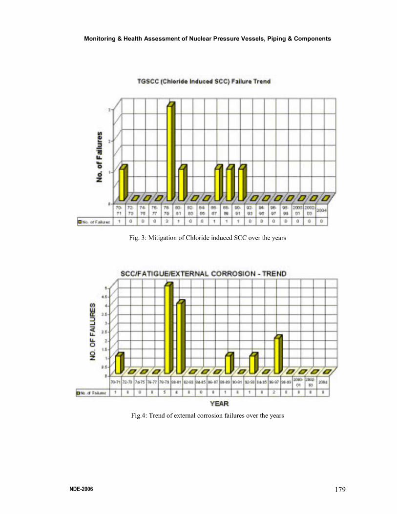
localize pitting corrosion. Fig.... shows the
trend of fatigue, external corrosion.
Therefore, a comprehensive review was
made and the vulnerable areas were
identified & inspected during regular IS1.
To overcome this problem, SS shims were
incorporated in-between the CS support and
the SS piping.
6.2 Carbon Steel Piping
Based on the evaluations the affected
piping is either replaced with the similar
material or with suitable material such as
Cr-Mo, in case of piping portions vulnerable
to Erosion-Corrosion. Special welding
procedures are developed for welding of Cr-
Mo piping components.
7. Conclusion
It is seen from the past three decades of
experience that the failure could be detected
through ISI effectively by Ultrasonic
examination, LPT, Visual examination and
system leak checks. At TAPS, many
remedial measures were taken to control and
mitigate stainless steel piping failures such
as;
(a) Enhanced In-Service Inspection of
austenitic stainless steel piping.
(b) Implementing the approved & qualified
Repair methodologies.
(c) Replacement of affected piping with
corrosion resistance material (SS-316L
or LN grade).
(d) Replacement of all conventional
insulation with reflective type metallic
insulation
The failure of large piping has not been
observed so far. This could be due to higher
thickness and residual stress patterns are
favorable for crack arrest. The inspection
programme has been strengthened based on
the feedback obtained from overseas
reactors experience from time to time in the
specific areas. Similarly, the carbon steel
piping/fittings vulnerable to erosion
corrosion were replaced with EC resistant
material based on the experience feed back
from in-hose and overseas experience as
well. Generic issues such as reactor core
shroud cracking are well addressed by
systematic inspection of all the accessible
areas and enhanced in-service inspection.
Therefore, ISI provides an effective tool for
prediction and monitoring the healthiness of
primary system piping, pressure vessels &
its integral attachments for continued
operation of TAPS units.
8. Acknowledgements
The authors are grateful to TAPS
Management for giving an opportunity to
publish this technical paper in National
Seminar on "Non-Destructive Evaluation
(NDE2006)".

A. Ramu et al.
NDE-2006 178
Fig. 1: Pattern of SS Piping failures with respect the pipe sizing
Fig. 2: Detection of failures-trend graph
Monitoring & Health Assessment of Nuclear Pressure Vessels, Piping & Components
NDE-2006 179
Fig. 3: Mitigation of Chloride induced SCC over the years
Fig.4: Trend of external corrosion failures over the years
A. Ramu et al.
NDE-2006 180
Fig. 5: Methodology to qualify Class-I system components for continued service, as per ASME
boiler and pressure vessel code, Section-XI
9. References
1. NUREG-0313 Rev.2 "Technical Report on
Material selection and processmg guidelines
for BWR coolant pressure boundary piping" (January 1988).
2. TAPS Manual No. 1975, Revision 2 on "In-
Service Inspection" (2000).
3. ASME Section XI "Rules for inspection and
testing of components of Light-Water
cooled plants" July 1998 Edition.
4. EPRI NDE Center "Introduction and
History of Flaw Sizing Technology".
5. 1982 Annual Progress Report " BWR
Owners Group Pipe Remedy Application
And Training Facility" prepared by Repair
Application Division, lA.Jones Applied
Research Company prepared for Dr. Joseph
C.Danko, Coordinator, BWROG IGSCC
Research Programme, EPRI (1983).
6. USNRC Regulatory Guide 1.36 on "Non-
metallic thermal insulation for Austenitic
Stainless Steel (February 1973).
7. ASME Section-XI, Division 1, Code case
N-480-l""Examination Requirements for Pipe wall Thinning Due to Single Phase
Erosion and Corrosion".
8. ASME Section-XI Division 1, Code Case
N-561-1 "Alternative Requirements for
Wall Thickness Restoration of Class 2 and
high Energy Class 3 carbon Steel Piping".
9. Joseph C. Danko "Igscc-recent experience reviewed" Nuclear Engineering
International, June-1984.
10. Mr. David Pitcairn, Mis Nutech
Engineers Inc.'" Advances in weld
overlay repair Technology" (1982).
Monitoring & Health Assessment of Nuclear Pressure Vessels, Piping & Components
NDE-2006 181
11. EPR-09-103: Nutech Engineers Inc."
ASME Code and Regulatory
Requirements for repairs and
replacements ofBWR Piping" (December 1982).


![Action Plan CEPI-Tarapur[1]](https://img.pdfslide.us/doc/110x75/54f834154a79591c638b527b/action-plan-cepi-tarapur1.jpg)