Embed Size (px)
Citation preview
7/26/2019 In-Service Feed water Heater Condition Assessment Using the Pulsed Eddy Current NDE Technology.pdf
http://slidepdf.com/reader/full/in-service-feed-water-heater-condition-assessment-using-the-pulsed-eddy-current 1/68
In-Service Feedwater Heater Condition
Assessment Using the Pulsed Eddy Current NDE Technology
Technical Report L
I
C
E N
S E D
M A T
E R
I
A
L
WARNING:Please read the Export Control
and License Agreement on theback cover before removing the Wrapping Material.
Effective December 6, 2006, this report has been made publicly
available in accordance with Section 734.3(b)(3) and published in
accordance with Section 734.7 of the U.S. Export Administration
Regulations. As a result of this publication, this report is subject to
only copyright protection and does not require any license
agreement from EPRI. This notice supersedes the export control
restrictions and any proprietary licensed material notices
embedded in the document prior to publication.

7/26/2019 In-Service Feed water Heater Condition Assessment Using the Pulsed Eddy Current NDE Technology.pdf
http://slidepdf.com/reader/full/in-service-feed-water-heater-condition-assessment-using-the-pulsed-eddy-current 2/68
7/26/2019 In-Service Feed water Heater Condition Assessment Using the Pulsed Eddy Current NDE Technology.pdf
http://slidepdf.com/reader/full/in-service-feed-water-heater-condition-assessment-using-the-pulsed-eddy-current 3/68
EPRI Project ManagersP. LaraK. Krzywosz
EPRI 3412 Hillview Avenue, Palo Alto, California 94304 • PO Box 10412, Palo Alto, California 94303 • USA800.313.3774 • 650.855.2121 • [email protected] • www.epri.com
In-Service Feedwater HeaterCondition Assessment Using the
Pulsed Eddy Current NDETechnology
1006372
Final Report, November 2001
7/26/2019 In-Service Feed water Heater Condition Assessment Using the Pulsed Eddy Current NDE Technology.pdf
http://slidepdf.com/reader/full/in-service-feed-water-heater-condition-assessment-using-the-pulsed-eddy-current 4/68
DISCLAIMER OF WARRANTIES AND LIMITATION OF LIABILITIES
THIS DOCUMENT WAS PREPARED BY THE ORGANIZATION(S) NAMED BELOW AS ANACCOUNT OF WORK SPONSORED OR COSPONSORED BY THE ELECTRIC POWER RESEARCHINSTITUTE, INC. (EPRI). NEITHER EPRI, ANY MEMBER OF EPRI, ANY COSPONSOR, THEORGANIZATION(S) BELOW, NOR ANY PERSON ACTING ON BEHALF OF ANY OF THEM:
(A) MAKES ANY WARRANTY OR REPRESENTATION WHATSOEVER, EXPRESS OR IMPLIED, (I)WITH RESPECT TO THE USE OF ANY INFORMATION, APPARATUS, METHOD, PROCESS, ORSIMILAR ITEM DISCLOSED IN THIS DOCUMENT, INCLUDING MERCHANTABILITY AND FITNESSFOR A PARTICULAR PURPOSE, OR (II) THAT SUCH USE DOES NOT INFRINGE ON ORINTERFERE WITH PRIVATELY OWNED RIGHTS, INCLUDING ANY PARTY'S INTELLECTUALPROPERTY, OR (III) THAT THIS DOCUMENT IS SUITABLE TO ANY PARTICULAR USER'SCIRCUMSTANCE; OR
(B) ASSUMES RESPONSIBILITY FOR ANY DAMAGES OR OTHER LIABILITY WHATSOEVER(INCLUDING ANY CONSEQUENTIAL DAMAGES, EVEN IF EPRI OR ANY EPRI REPRESENTATIVEHAS BEEN ADVISED OF THE POSSIBILITY OF SUCH DAMAGES) RESULTING FROM YOURSELECTION OR USE OF THIS DOCUMENT OR ANY INFORMATION, APPARATUS, METHOD,PROCESS, OR SIMILAR ITEM DISCLOSED IN THIS DOCUMENT.
ORGANIZATION(S) THAT PREPARED THIS DOCUMENT
EPRI
ORDERING INFORMATION
Requests for copies of this report should be directed to EPRI Customer Fulfillment, 1355 Willow Way,Suite 278, Concord, CA 94520, (800) 313-3774, press 2.
Electric Power Research Institute and EPRI are registered service marks of the Electric PowerResearch Institute, Inc. EPRI. ELECTRIFY THE WORLD is a service mark of the Electric PowerResearch Institute, Inc.
Copyright © 2001 Electric Power Research Institute, Inc. All rights reserved.
7/26/2019 In-Service Feed water Heater Condition Assessment Using the Pulsed Eddy Current NDE Technology.pdf
http://slidepdf.com/reader/full/in-service-feed-water-heater-condition-assessment-using-the-pulsed-eddy-current 5/68
iii
CITATIONS
This report was prepared by
EPRI
1300 W.T. Harris Boulevard
Charlotte, NC 28262
Principal Investigators
P. Lara
K. Krzywosz
This report describes research sponsored by EPRI.
The report is a corporate document that should be cited in the literature in the following manner:
In-Service Feedwater Heater Condition Assessment Using the Pulsed Eddy Current NDE
Technology, EPRI, Palo Alto, CA: 2001. 1006372.

7/26/2019 In-Service Feed water Heater Condition Assessment Using the Pulsed Eddy Current NDE Technology.pdf
http://slidepdf.com/reader/full/in-service-feed-water-heater-condition-assessment-using-the-pulsed-eddy-current 6/68
7/26/2019 In-Service Feed water Heater Condition Assessment Using the Pulsed Eddy Current NDE Technology.pdf
http://slidepdf.com/reader/full/in-service-feed-water-heater-condition-assessment-using-the-pulsed-eddy-current 7/68
v
REPORT SUMMARY
This report highlights the performance characteristics of the pulsed eddy current technology for
the in-service examination of feedwater heater shells through insulation. The purpose is to help
the utility make an informed decision about applying the pulsed eddy current technology on-line
or examining the heater more conventionally by removing the insulation and performing
thickness measurements with ultrasonics during the outage season.
Background
Feedwater heater shells have been reported to be susceptible to flow-accelerated corrosion (FAC)at both PWR and BWR nuclear stations. Feedwater shell leaks are safety significant and, once
detected, require immediate plant shutdown for repair. Because of the seriousness of the event,
utilities have instituted regular inspection programs to monitor the condition of the feedwater
shells and track the progress of the erosion damage.
Because the feedwater heaters are insulated, in some cases with asbestos material, many utilities
have recently opted to examine the shells with pulsed eddy current technology in order to avoid
the cost of insulation removal. This initiative is further justified by the ability of the technology
to be deployed while the heaters are in-service, allowing the screening and prioritization of
examination areas prior to the forthcoming outage.
Objective• To determine the effectiveness of the pulsed eddy current technology to assess shell
condition when surveying feedwater heaters on-line and through insulation
ApproachThis technology evaluation relied on analyzing the results obtained at four nuclear power stations
by comparing the in-service pulsed eddy current results with the more conventional ultrasonic
measurements obtained while the heaters were off-line and the insulation removed.
ResultsThe following results were obtained from the evaluations:
• In cases of wear with large areal extent, the pulsed eddy current and ultrasonic wear patterns
matched closely.
• In cases of wear with relatively small areal extent, the pulsed eddy current technology did not
indicate the presence of FAC damage.
• The FAC safety factor should be increased when assessing feedwater heater shells with
pulsed eddy current technology.
7/26/2019 In-Service Feed water Heater Condition Assessment Using the Pulsed Eddy Current NDE Technology.pdf
http://slidepdf.com/reader/full/in-service-feed-water-heater-condition-assessment-using-the-pulsed-eddy-current 8/68
vi
• The pulsed eddy current detection threshold is determined by the FAC areal extent and vessel
wall loss.
• To ensure proper application of the technology, the detection threshold must be considered in
conjunction with the corrosion allowance of the heater.
EPRI PerspectivePulsed eddy current technology represents an important advance in nondestructive examination
technologies. The technology permits obtaining thickness measurement of feedwater heaters
though insulation while they are in service. This quality is particularly useful in PWR plants
where the heaters are located outside the containment building, allowing the utility to examine
the vessel outside the outage season. The technology exhibits limitations and is best suited for
the detection of erosion processes that affect the vessel wall over a relatively large areal extent.
EPRI plans to work with the technology developer to reduce the pulsed eddy current examination
footprint.
Keywords
Feedwater heaterPulsed eddy current
Insulation
Erosion
Flow-accelerated corrosion
FAC
7/26/2019 In-Service Feed water Heater Condition Assessment Using the Pulsed Eddy Current NDE Technology.pdf
http://slidepdf.com/reader/full/in-service-feed-water-heater-condition-assessment-using-the-pulsed-eddy-current 9/68
EPRI Licensed Material
vii
ACKNOWLEDGMENTS
The following nuclear power stations contributed examination information about their feedwater
heater conditions to this project:
Callaway
Fort Calhoun
Millstone
Nine Mile Point
Palo Verde
VogtleWolf Creek
The following individuals contributed to this project by sharing their examination experiences
with EPRI:
Russell Bowie, Calvert Cliffs
Danny Cordes, Southern Nuclear
Carlos Hernandez, Wolf Creek
Paul Huffman, Browns Ferry
Steve Janes, Millstone
Robert Kokoska, CallawayDean Leimbach, Susquehanna
Hazel Malone, Indian Point
Tim Oldfield, Nine Mile Point
David Rollins, Fort Calhoun
Steve Slosnerick, Davis Besse
Willie Smith, Vogtle
Gerry Story, Palo VerdeJames Wadsworth, Nine Mile Point

7/26/2019 In-Service Feed water Heater Condition Assessment Using the Pulsed Eddy Current NDE Technology.pdf
http://slidepdf.com/reader/full/in-service-feed-water-heater-condition-assessment-using-the-pulsed-eddy-current 10/68
EPRI Licensed Material
viii
The following individuals from Aptech Engineering contributed to this project:
Marvin Cohn
Andrew Holuszko
Ken Lobo
Jordan Norton
Aptech Engineering performed the pulsed eddy current examinations included in this report.
Their contribution to this project is acknowledged and deeply appreciated.
7/26/2019 In-Service Feed water Heater Condition Assessment Using the Pulsed Eddy Current NDE Technology.pdf
http://slidepdf.com/reader/full/in-service-feed-water-heater-condition-assessment-using-the-pulsed-eddy-current 11/68
EPRI Licensed Material
ix
CONTENTS
1 OBJECTIVE .........................................................................................................................1-1
2 BACKGROUND ...................................................................................................................2-1
3 MECHANISM AND MORPHOLOGY....................................................................................3-1
3.1 Mechanism ................................................................................................................3-1
3.2 Morphology................................................................................................................3-3
4 INSPECTION OPTIONS.......................................................................................................4-1
4.1 The Pulsed Eddy Current Technology........................................................................4-1
4.2 Pulsed Eddy Current Principles of Operation .............................................................4-2
4.3 Pulsed Eddy Current Field Operation.........................................................................4-4
4.3.1 Adjustments to Calibration Shifts...........................................................................4-7
4.3.2 Interpretation of Corrosion Indications ...................................................................4-8
5 PULSED EDDY CURRENT FIELD EVALUATION...............................................................5-1
6 DISCUSSION .......................................................................................................................6-1
7 CONCLUSIONS ...................................................................................................................7-1
8 REFERENCES .....................................................................................................................8-1

7/26/2019 In-Service Feed water Heater Condition Assessment Using the Pulsed Eddy Current NDE Technology.pdf
http://slidepdf.com/reader/full/in-service-feed-water-heater-condition-assessment-using-the-pulsed-eddy-current 12/68
7/26/2019 In-Service Feed water Heater Condition Assessment Using the Pulsed Eddy Current NDE Technology.pdf
http://slidepdf.com/reader/full/in-service-feed-water-heater-condition-assessment-using-the-pulsed-eddy-current 13/68
EPRI Licensed Material
xi
LIST OF FIGURES
Figure 3-1 FAC Wear Patterns near a Steam Extraction Inlet Nozzle at Plant A(Measurements Were Performed with Ultrasonics on a 2-Inch [50.8-mm] Grid) ...............3-3
Figure 3-2 Recommended Examination Coverage in the Circumferential Direction..................3-4
Figure 3-3 Recommended Examination Coverage in the Axial Direction..................................3-5
Figure 4-1 Pulsed Eddy Current Field Representation .............................................................4-3
Figure 4-2 PEC Operator Placing the Pulsed Eddy Current Sensor on the FeedwaterHeater Insulation ..............................................................................................................4-4
Figure 4-3 PEC Operator Running the Data Acquisition System..............................................4-5Figure 4-4 Computer Screen Image of the Incotest System.....................................................4-6
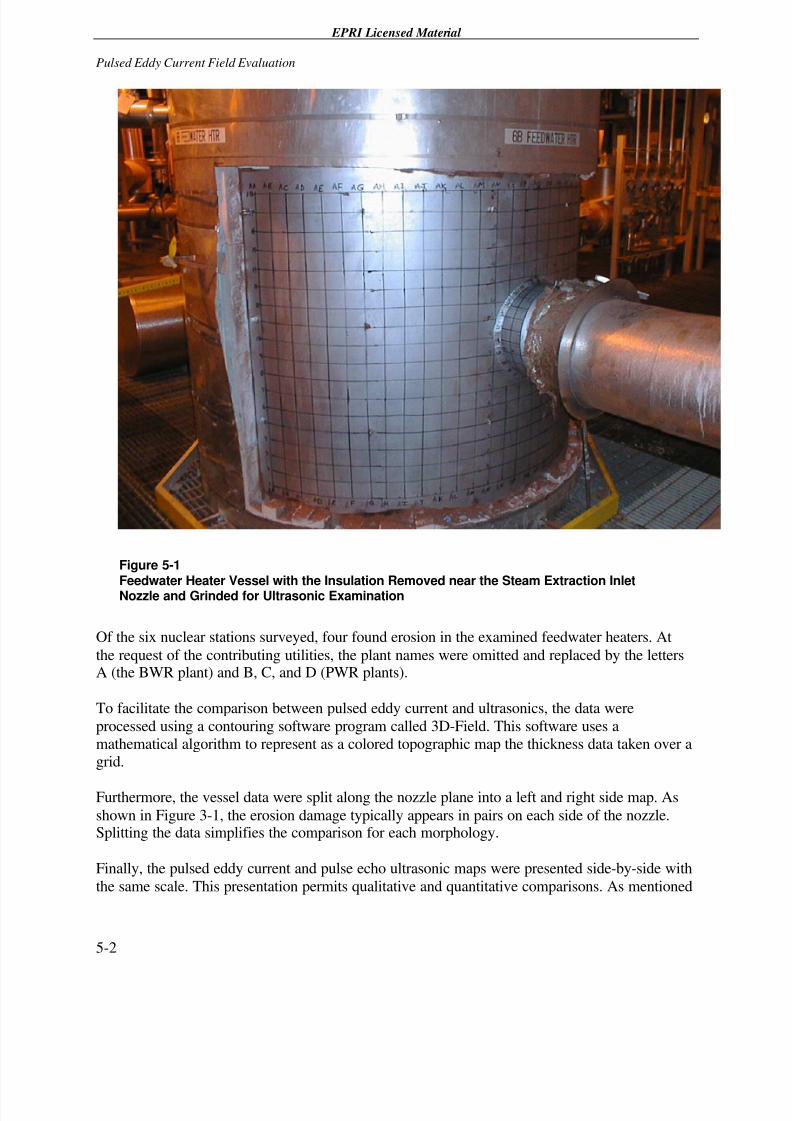
Figure 5-1 Feedwater Heater Vessel with the Insulation Removed near the SteamExtraction Inlet Nozzle and Grinded for Ultrasonic Examination .......................................5-2
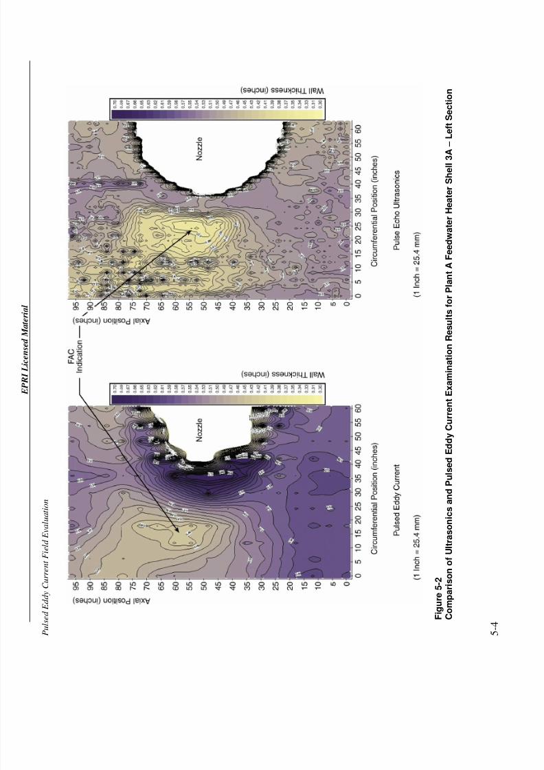
Figure 5-2 Comparison of Ultrasonics and Pulsed Eddy Current Examination Results forPlant A Feedwater Heater Shell 3A – Left Section ...........................................................5-4
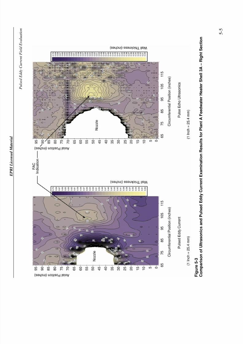
Figure 5-3 Comparison of Ultrasonics and Pulsed Eddy Current Examination Results forPlant A Feedwater Heater Shell 3A – Right Section .........................................................5-5
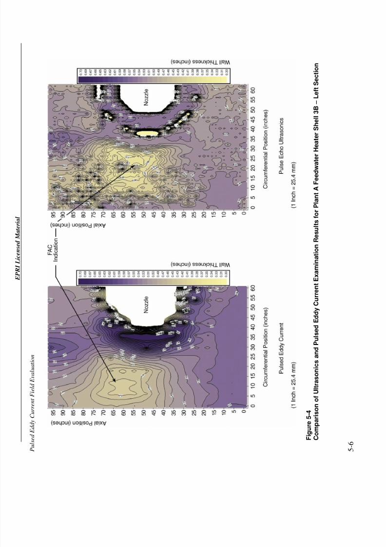
Figure 5-4 Comparison of Ultrasonics and Pulsed Eddy Current Examination Results forPlant A Feedwater Heater Shell 3B – Left Section ...........................................................5-6
Figure 5-5 Comparison of Ultrasonics and Pulsed Eddy Current Examination Results forPlant A Feedwater Heater Shell 3B – Right Section .........................................................5-7
Figure 5-6 Comparison of Ultrasonics and Pulsed Eddy Current Examination Results forPlant A Feedwater Heater Shell 3C – Left Section ...........................................................5-8
Figure 5-7 Comparison of Ultrasonics and Pulsed Eddy Current Examination Results forPlant A Feedwater Heater Shell 3C – Right Section.........................................................5-9
Figure 5-8 Comparison of Ultrasonics and Pulsed Eddy Current Examination Results forPlant B Feedwater Heater Shell 2B – Left Section .........................................................5-10
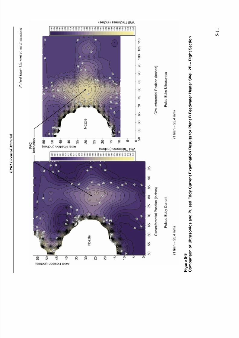
Figure 5-9 Comparison of Ultrasonics and Pulsed Eddy Current Examination Results forPlant B Feedwater Heater Shell 2B – Right Section .......................................................5-11
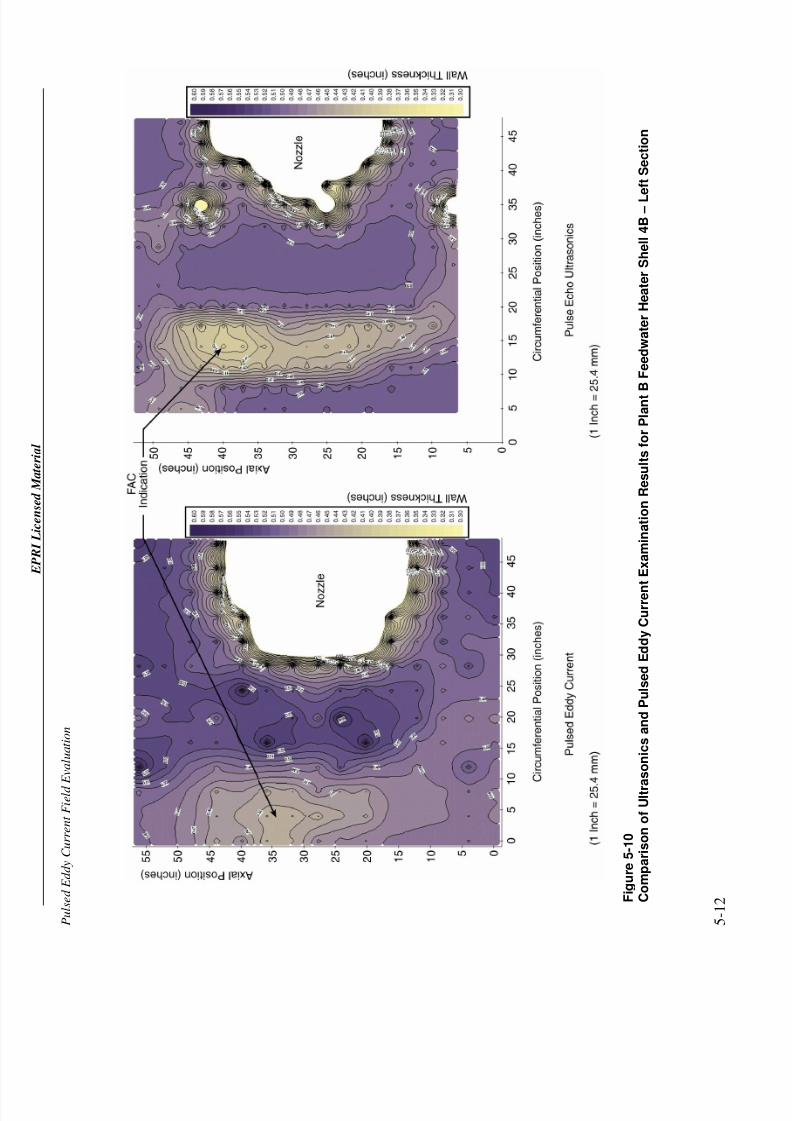
Figure 5-10 Comparison of Ultrasonics and Pulsed Eddy Current Examination Resultsfor Plant B Feedwater Heater Shell 4B – Left Section ....................................................5-12
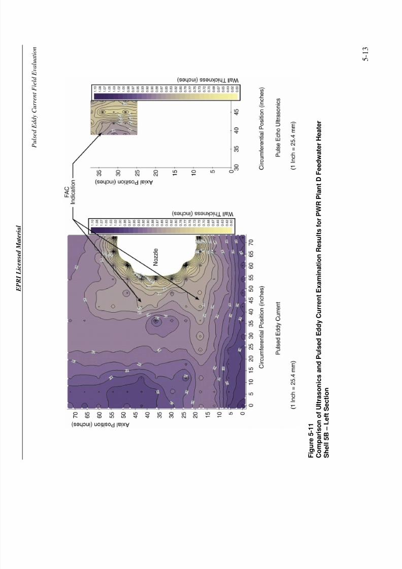
Figure 5-11 Comparison of Ultrasonics and Pulsed Eddy Current Examination Resultsfor PWR Plant D Feedwater Heater Shell 5B – Left Section..........................................5-13
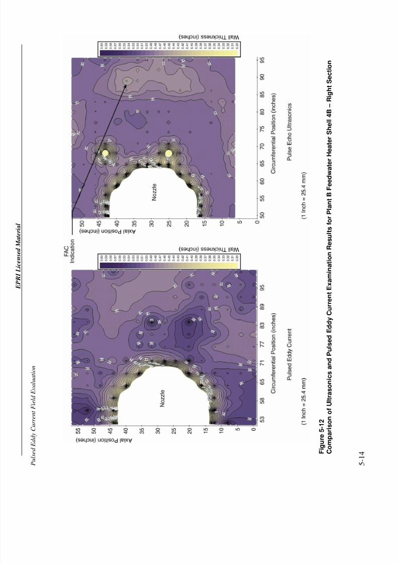
Figure 5-12 Comparison of Ultrasonics and Pulsed Eddy Current Examination Resultsfor Plant B Feedwater Heater Shell 4B – Right Section..................................................5-14
Figure 5-13 Comparison of Ultrasonics and Pulsed Eddy Current Examination Resultsfor Vogtle Unit 2 Feedwater Heater Shell 6A – Left Section...........................................5-15
7/26/2019 In-Service Feed water Heater Condition Assessment Using the Pulsed Eddy Current NDE Technology.pdf
http://slidepdf.com/reader/full/in-service-feed-water-heater-condition-assessment-using-the-pulsed-eddy-current 14/68
EPRI Licensed Material
xii
Figure 5-14 Comparison of Ultrasonics and Pulsed Eddy Current Examination Resultsfor Vogtle Unit 2 Feedwater Heater Shell 6A – Right Section .........................................5-16
Figure 5-15 Comparison of Ultrasonics and Pulsed Eddy Current Examination Resultsfor Vogtle Unit 2 Feedwater Heater Shell 6B – Left Section............................................5-17
Figure 5-16 Comparison of Ultrasonics and Pulsed Eddy Current Examination Results
for Vogtle Unit 2 Feedwater Heater Shell 6B – Right Section .........................................5-18Figure 5-17 Comparison of Ultrasonics and Pulsed Eddy Current Examination Results
for PWR Plant D Feedwater Heater Shell 5B – Right Section.........................................5-19
Figure 5-18 Relationship Between Detection and Circumferential Length of the Damagefor Pulsed Eddy Current Technology..............................................................................5-20
Figure 5-19 Wall Loss Correlation Between the Pulsed Eddy Current and UltrasonicEvaluations ....................................................................................................................5-20
Figure 6-1 Pulsed Eddy Current Detection Threshold for Feedwater Heater Shells with 3Inches (76.2 mm) of Insulation .........................................................................................6-1

7/26/2019 In-Service Feed water Heater Condition Assessment Using the Pulsed Eddy Current NDE Technology.pdf
http://slidepdf.com/reader/full/in-service-feed-water-heater-condition-assessment-using-the-pulsed-eddy-current 15/68
EPRI Licensed Material
xiii
LIST OF TABLES
Table 2-1 Nuclear Power Stations That Have Found Evidence of FAC and HaveInstituted FAC Monitoring Programs.................................................................................2-1
Table 3-1 Nine Mile Unit 1 Feedwater Heater Shell Erosion Risk Factors ................................3-2
Table 5-1 Evaluation Results .................................................................................................5-23

7/26/2019 In-Service Feed water Heater Condition Assessment Using the Pulsed Eddy Current NDE Technology.pdf
http://slidepdf.com/reader/full/in-service-feed-water-heater-condition-assessment-using-the-pulsed-eddy-current 16/68
7/26/2019 In-Service Feed water Heater Condition Assessment Using the Pulsed Eddy Current NDE Technology.pdf
http://slidepdf.com/reader/full/in-service-feed-water-heater-condition-assessment-using-the-pulsed-eddy-current 17/68
EPRI Licensed Material
1-1
1 OBJECTIVE
The objective of this program was to determine the effectiveness of the pulsed eddy current
technology for assessing the shell condition when surveying feedwater heaters on-line and
through insulation. The program highlighted the advantages and limitations of the technology so
that utilities can make informed decisions about applying the pulsed eddy current inspection or
examining the heater more conventionally by removing the insulation and performing thicknessmeasurements with ultrasonics.

7/26/2019 In-Service Feed water Heater Condition Assessment Using the Pulsed Eddy Current NDE Technology.pdf
http://slidepdf.com/reader/full/in-service-feed-water-heater-condition-assessment-using-the-pulsed-eddy-current 18/68
7/26/2019 In-Service Feed water Heater Condition Assessment Using the Pulsed Eddy Current NDE Technology.pdf
http://slidepdf.com/reader/full/in-service-feed-water-heater-condition-assessment-using-the-pulsed-eddy-current 19/68
EPRI Licensed Material
2-1
2 BACKGROUND
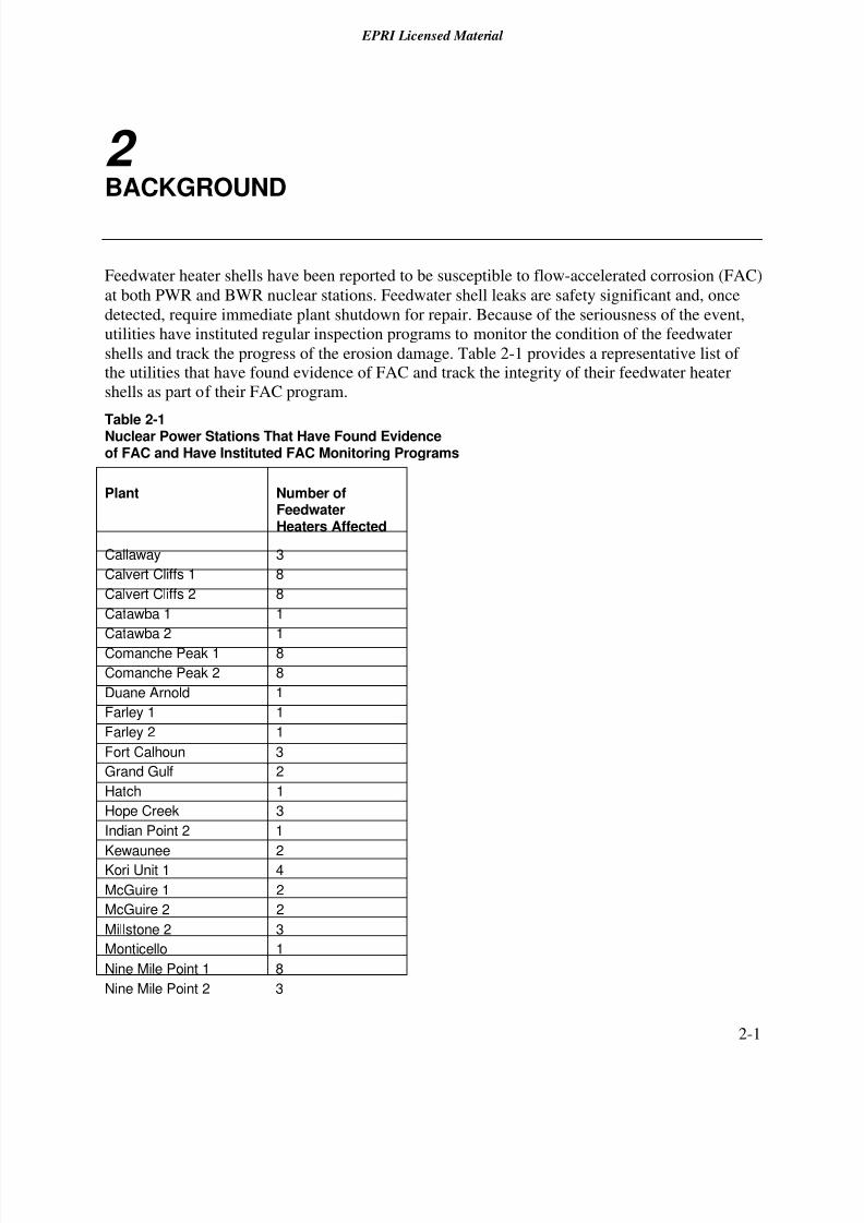
Feedwater heater shells have been reported to be susceptible to flow-accelerated corrosion (FAC)
at both PWR and BWR nuclear stations. Feedwater shell leaks are safety significant and, once
detected, require immediate plant shutdown for repair. Because of the seriousness of the event,
utilities have instituted regular inspection programs to monitor the condition of the feedwater
shells and track the progress of the erosion damage. Table 2-1 provides a representative list of
the utilities that have found evidence of FAC and track the integrity of their feedwater heater
shells as part of their FAC program.
Table 2-1Nuclear Power Stations That Have Found Evidenceof FAC and Have Instituted FAC Monitoring Programs
Plant Number ofFeedwaterHeaters Affected
Callaway 3
Calvert Cliffs 1 8
Calvert Cliffs 2 8
Catawba 1 1
Catawba 2 1
Comanche Peak 1 8
Comanche Peak 2 8
Duane Arnold 1
Farley 1 1
Farley 2 1
Fort Calhoun 3
Grand Gulf 2
Hatch 1
Hope Creek 3
Indian Point 2 1
Kewaunee 2Kori Unit 1 4
McGuire 1 2
McGuire 2 2
Millstone 2 3
Monticello 1
Nine Mile Point 1 8
Nine Mile Point 2 3
7/26/2019 In-Service Feed water Heater Condition Assessment Using the Pulsed Eddy Current NDE Technology.pdf
http://slidepdf.com/reader/full/in-service-feed-water-heater-condition-assessment-using-the-pulsed-eddy-current 20/68
EPRI Licensed Material
Background
2-2
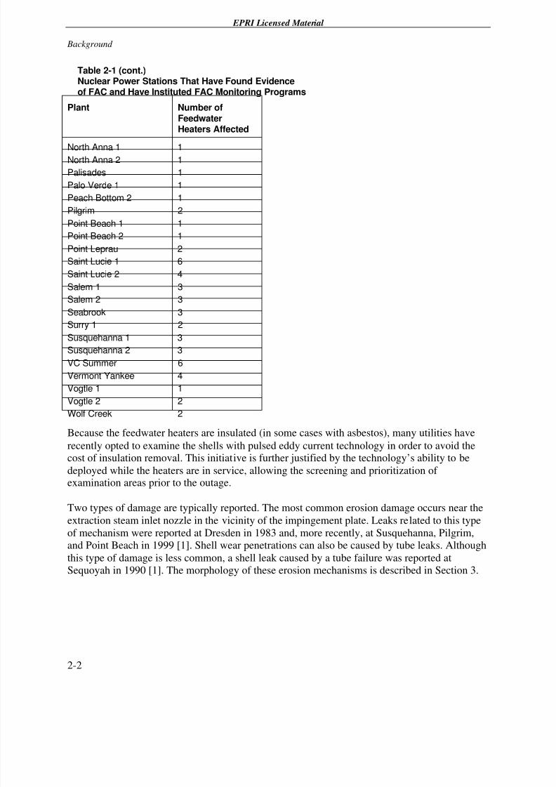
Table 2-1 (cont.) Nuclear Power Stations That Have Found Evidence of FAC and Have Instituted FAC Monitoring Programs
Plant Number ofFeedwaterHeaters Affected
North Anna 1 1
North Anna 2 1
Palisades 1
Palo Verde 1 1
Peach Bottom 2 1
Pilgrim 2
Point Beach 1 1
Point Beach 2 1
Point Leprau 2
Saint Lucie 1 6
Saint Lucie 2 4Salem 1 3
Salem 2 3
Seabrook 3
Surry 1 2
Susquehanna 1 3
Susquehanna 2 3
VC Summer 6
Vermont Yankee 4
Vogtle 1 1
Vogtle 2 2
Wolf Creek 2
Because the feedwater heaters are insulated (in some cases with asbestos), many utilities have
recently opted to examine the shells with pulsed eddy current technology in order to avoid the
cost of insulation removal. This initiative is further justified by the technology’s ability to be
deployed while the heaters are in service, allowing the screening and prioritization of examination areas prior to the outage.
Two types of damage are typically reported. The most common erosion damage occurs near the
extraction steam inlet nozzle in the vicinity of the impingement plate. Leaks related to this type
of mechanism were reported at Dresden in 1983 and, more recently, at Susquehanna, Pilgrim,
and Point Beach in 1999 [1]. Shell wear penetrations can also be caused by tube leaks. Although
this type of damage is less common, a shell leak caused by a tube failure was reported at
Sequoyah in 1990 [1]. The morphology of these erosion mechanisms is described in Section 3.
7/26/2019 In-Service Feed water Heater Condition Assessment Using the Pulsed Eddy Current NDE Technology.pdf
http://slidepdf.com/reader/full/in-service-feed-water-heater-condition-assessment-using-the-pulsed-eddy-current 21/68
EPRI Licensed Material
3-1
3 MECHANISM AND MORPHOLOGY
This section presents information on the FAC mechanism and damage morphology in feedwater
heaters. Understanding the corrosion mechanism and the inspection target is an important part of a feedwater examination program.
3.1 Mechanism
The mechanism that causes FAC is a combination of metal oxidation from iron to magnetite and
the dissolution or removal of the magnetite layer by the fluid flow. At low fluid velocities, themagnetite dissolves slowly enough that a protective layer is formed on the metal surface. Under
these conditions, the rate of corrosion is relatively slow and controlled by the mass transfer of ions through the magnetite layer. As the fluid velocity increases above the breakaway value, the
protective oxide film is removed by the surface shear stress and mass transport processes,significantly accelerating the corrosion rates and causing FAC [2].
The mechanism suggests that impurities contributing to the dissolution of the protective layer
enhance the corrosion process. Parameters that have been identified as contributing to thisdissolution include hydrazine concentration, pH, operating temperature of the heater, metallurgy,liner presence, steam quality, and impingement plate geometry.
In the feedwater system, oxygen levels are controlled by adding hydrazine, a scavenging agent.
Although oxygen contributes to the corrosion process, the total removal of oxygen from the
system is detrimental because no protective magnetite layer can be formed. The presence of traces of oxygen (in the range of 100 parts per billion [ppb]) in the transported fluid is typically
recommended [2]. Hydrazine, though, enhances FAC by reducing the levels of oxygen and byreacting with the elements that form the protective layer [2]. In PWR plants, high levels of
hydrazine (greater than 100 ppb) are recommended in order to mitigate intergranular stresscorrosion cracking (IGSCC). However, these high levels of hydrazine increase the likelihood of FAC damage.
Hydrogen concentration, as measured by the pH, also promotes the dissolution of the protectivemagnetite layer [2]. Accordingly, feedwater systems with pH levels less than 6.3 are consideredto be at risk of FAC damage [1].
Temperature plays an important role in FAC by enhancing the corrosion reactions. FAC rates are
reported to peak at about 300°F (149°C) and fall off at higher temperatures under laboratoryconditions. However, because this result depends on the testing variables, it is not generally
7/26/2019 In-Service Feed water Heater Condition Assessment Using the Pulsed Eddy Current NDE Technology.pdf
http://slidepdf.com/reader/full/in-service-feed-water-heater-condition-assessment-using-the-pulsed-eddy-current 22/68
EPRI Licensed Material
Mechanism and Morphology
3-2
accepted as a trend. A more conventional view considers components to be prone to FAC attemperatures greater than 300°F (149°C) [1].
Shell metallurgy that promotes the formation of a protective layer tends to mitigate FAC.
Generally, chromium is considered to be the most beneficial alloying element to carbon steel,
and levels above 1.25% are generally required for the alloy to be classified as FAC resistant [3].However, under FAC attack, small increases in chromium (for example, from 0.02%, which is
typical of mild carbon steel, to 0.1%) have been reported to significantly reduce the FAC rate[2]. Some feedwater heater designs mitigate FAC by installing a stainless steel liner over thesurfaces that are prone to corrosion damage.
Steam quality significantly affects FAC wear rates. The electrochemical reactions that promote
the dissolution of the protective layer can occur only if the surface is wet; that is, FAC cannot
occur in a dry steam environment [3]. In addition, decreasing the steam quality leads to highershear stress and higher mass transfer (by increasing the liquid Reynolds number), which leads toincreased dissolution of the protective layer [2].
The geometry of the component also plays an important role in FAC: locations where the fluid
dynamics exhibit vortices, secondary flows, or turbulence are more prone to FAC [3]. Infeedwater heaters, the steam entering through the extraction steam inlet nozzle is redirected in
the circumferential direction after impinging on the horizontal plate that protects the tube bundle.When the plate is built flat, the location past the gap between the plate and the shell exhibits the
highest steam velocity, while the plate corner is likely to promote the development of vorticesand secondary flows. In this scenario, the location past the impingement plate is prone to FAC
damage. As a rule, heaters with flat (rather than curved) impingement plates and gaps less than1/4 of the nozzle diameter are considered susceptible to FAC.
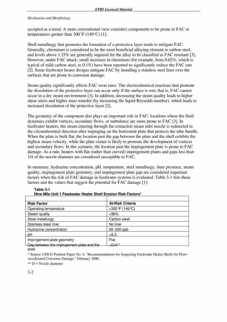
In summary, hydrazine concentration, pH, temperature, steel metallurgy, liner presence, steamquality, impingement plate geometry, and impingement plate gap are considered importantfactors when the risk of FAC damage in feedwater systems is evaluated. Table 3-1 lists thesefactors and the values that suggest the potential for FAC damage [1].
Table 3-1Nine Mile Unit 1 Feedwater Heater Shell Erosion Risk Factors*
Risk Factor At-Risk Criteria
Operating temperature >300°F (149°C)
Steam quality <96%
Steel metallurgy Carbon steel
Stainless steel liner No linerHydrazine concentration 50 – 200 ppb
pH <6.3
Impingement plate geometry Flat
Gap between the impingement plate and theshell
<D/4**
* Source: CHUG Position Paper No. 4, "Recommendations for Inspecting Feedwater Heater Shells for Flow-
Accelerated Corrosion Damage," February 2000.
** D = Nozzle diameter
7/26/2019 In-Service Feed water Heater Condition Assessment Using the Pulsed Eddy Current NDE Technology.pdf
http://slidepdf.com/reader/full/in-service-feed-water-heater-condition-assessment-using-the-pulsed-eddy-current 23/68
EPRI Licensed Material
Mechanism and Morphology
3-3
3.2 Morphology
As mentioned in Section 2, FAC damage in feedwater heaters can be classified into two types:
erosion in the vicinity of the extraction steam inlet nozzle and wall loss caused by the steam jetfrom a leaking tube.
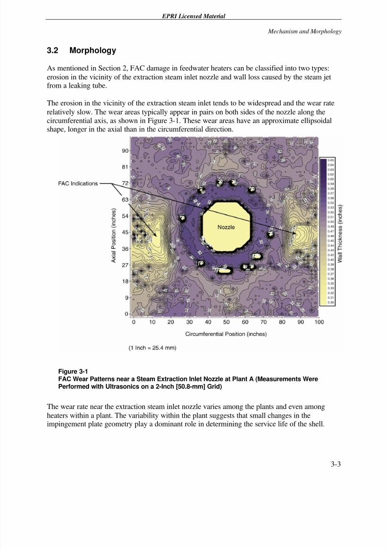
The erosion in the vicinity of the extraction steam inlet tends to be widespread and the wear rate
relatively slow. The wear areas typically appear in pairs on both sides of the nozzle along thecircumferential axis, as shown in Figure 3-1. These wear areas have an approximate ellipsoidalshape, longer in the axial than in the circumferential direction.
Figure 3-1FAC Wear Patterns near a Steam Extraction Inlet Nozzle at Plant A (Measurements Were
Performed with Ultrasonics on a 2-Inch [50.8-mm] Grid)
The wear rate near the extraction steam inlet nozzle varies among the plants and even among
heaters within a plant. The variability within the plant suggests that small changes in theimpingement plate geometry play a dominant role in determining the service life of the shell.
7/26/2019 In-Service Feed water Heater Condition Assessment Using the Pulsed Eddy Current NDE Technology.pdf
http://slidepdf.com/reader/full/in-service-feed-water-heater-condition-assessment-using-the-pulsed-eddy-current 24/68
EPRI Licensed Material
Mechanism and Morphology
3-4
Because of this wear rate variability, use of the “sister-train” logic is not recommended when
evaluating a heater for potential erosion damage near the extraction steam inlet. The sister-trainlogic proposes that a component does not require inspection when an equivalent component in a
parallel train has shown no erosion damage. It is recommended that all the heaters are inspectedand their wear rates quantified before shell life assessments are made.
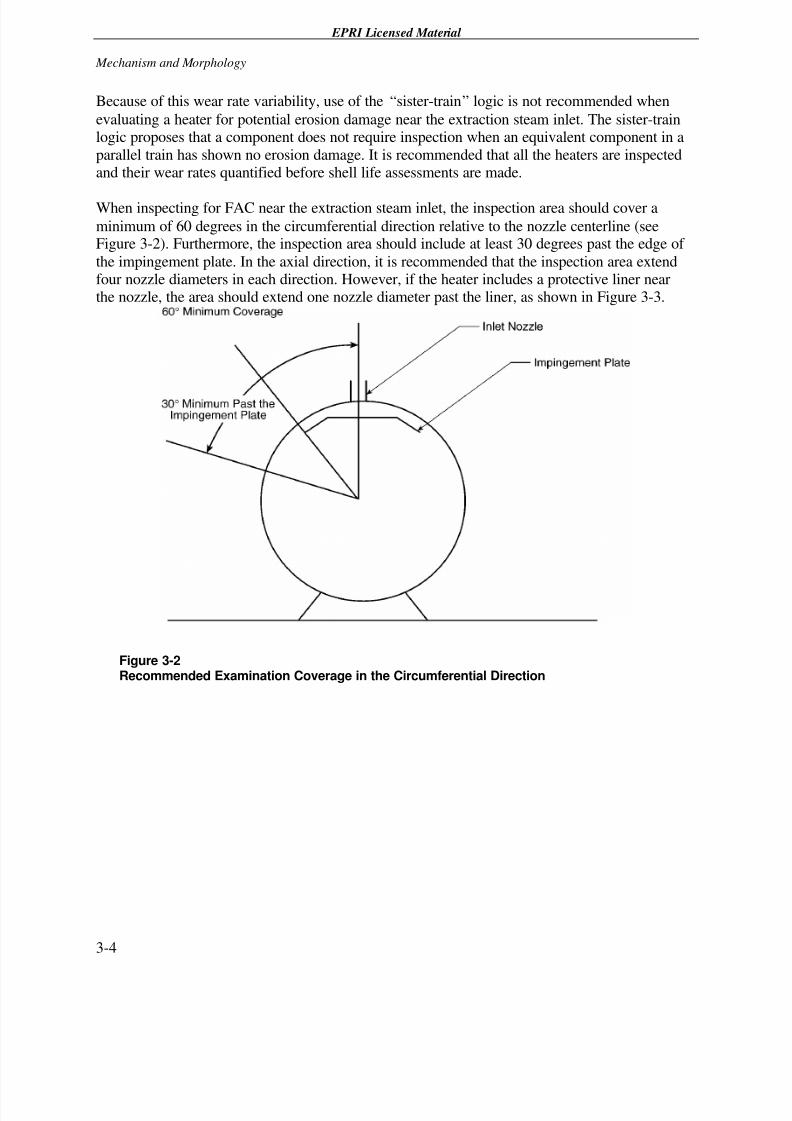
When inspecting for FAC near the extraction steam inlet, the inspection area should cover a
minimum of 60 degrees in the circumferential direction relative to the nozzle centerline (seeFigure 3-2). Furthermore, the inspection area should include at least 30 degrees past the edge of
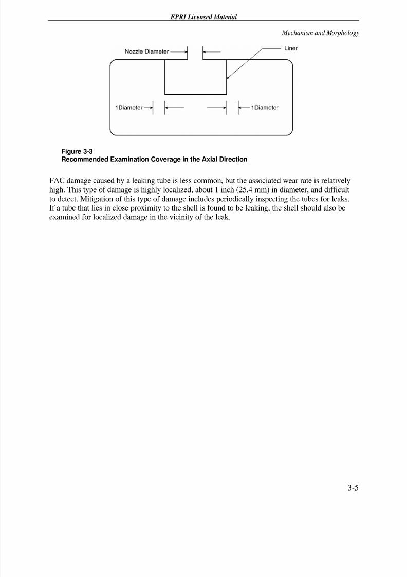
the impingement plate. In the axial direction, it is recommended that the inspection area extendfour nozzle diameters in each direction. However, if the heater includes a protective liner nearthe nozzle, the area should extend one nozzle diameter past the liner, as shown in Figure 3-3.
Figure 3-2Recommended Examination Coverage in the Circumferential Direction
7/26/2019 In-Service Feed water Heater Condition Assessment Using the Pulsed Eddy Current NDE Technology.pdf
http://slidepdf.com/reader/full/in-service-feed-water-heater-condition-assessment-using-the-pulsed-eddy-current 25/68
EPRI Licensed Material
Mechanism and Morphology
3-5
Figure 3-3Recommended Examination Coverage in the Axial Direction
FAC damage caused by a leaking tube is less common, but the associated wear rate is relatively
high. This type of damage is highly localized, about 1 inch (25.4 mm) in diameter, and difficult
to detect. Mitigation of this type of damage includes periodically inspecting the tubes for leaks.If a tube that lies in close proximity to the shell is found to be leaking, the shell should also beexamined for localized damage in the vicinity of the leak.

7/26/2019 In-Service Feed water Heater Condition Assessment Using the Pulsed Eddy Current NDE Technology.pdf
http://slidepdf.com/reader/full/in-service-feed-water-heater-condition-assessment-using-the-pulsed-eddy-current 26/68
7/26/2019 In-Service Feed water Heater Condition Assessment Using the Pulsed Eddy Current NDE Technology.pdf
http://slidepdf.com/reader/full/in-service-feed-water-heater-condition-assessment-using-the-pulsed-eddy-current 27/68
EPRI Licensed Material
4-1
4 INSPECTION OPTIONS
When inspecting for shell wear damage near the extraction steam inlet nozzle, the utility may
remove the insulation and perform ultrasonic thickness measurements over a 2- to 3-inch (50.8-
to 76.2-mm) grid or perform the measurements through the insulation with the pulsed eddycurrent technology over a 6-inch (152.4-mm) grid.
Many utilities have opted to use the pulsed eddy current technology for determining the
feedwater heater condition to minimize the cost of insulation removal. For PWR plants, pulsededdy current has the additional advantage that it can be performed on-line while the plant is in
operation, allowing the utility to screen out the areas that require ultrasonic evaluation during theoutage. The increased usage of pulsed eddy current requires better understanding of the
performance characteristics of this new technology. Accordingly, the information contained inthis report compares the feedwater heater evaluation results when using both pulsed eddy current
and ultrasonics to help users understand the conditions under which the pulsed eddy currentmethod can be appropriately applied.
4.1 The Pulsed Eddy Current Technology
The pulsed eddy current technology evaluated in this program was developed by RTD
(Netherlands) under license from ARCO and is available commercially under the name of Incotest. Aptech Engineering performed the examination and data reporting for the feedwaterheaters examined in this report.
Pulsed eddy current detects the presence of defects by inducing eddy currents in the insulation
jacket and in the outside surface of the pipe and monitoring the change in the magnetic field asthe currents diffuse and permeate the pipe’s and jacket’s wall. The wall thickness is then
measured by recording the time it takes for the currents to diffuse and permeate the pipe wall andcomparing that time with calibration standards.
Pulsed eddy current is increasingly used for feedwater heater condition assessments for the
following reasons:• The technology measures the wall thickness of the heater through the insulation, minimizing
the cost of insulation removal.
• It can penetrate carbon steel wall up to several inches thick.
• Because the probe requires no contact with the shell, pulsed eddy current
– Can be applied to hot heaters on-line.
7/26/2019 In-Service Feed water Heater Condition Assessment Using the Pulsed Eddy Current NDE Technology.pdf
http://slidepdf.com/reader/full/in-service-feed-water-heater-condition-assessment-using-the-pulsed-eddy-current 28/68
EPRI Licensed Material
Inspection Options
4-2
– Is not affected by the heater’s curvature.
– Is not affected by the presence of coatings or cladding.
– Is not affected by the insulation type.
– Measurements can be compensated for liftoff and jacket material type.
– Is tolerant of misalignment and rocking.
– Is tolerant of varying levels of operator skill.
However, the technique focuses on a relatively large area, which limits its application to
widespread corrosion (as is the case in FAC) [4, 5, 6, 7]. Limitations of the technology includethe following:
• Unable to assess small, localized areas
• May underestimate wall loss
• May miss areas of localized damage
• May require recalibration at various locations in the vessel
The principles of operation are described in Section 4.2.
4.2 Pulsed Eddy Current Principles of Operation
The pulsed eddy current technology allows thickness measurements through insulation by
inducing eddy currents on the vessel’s external surface and monitoring the currents as theydiffuse through the vessel wall.
The probe consists of a transmitter and a receiver coil. The coil geometry varies, depending onthe application, and is arranged to minimize the target area of the eddy current field.
During operation, the system energizes the transmitter coil by sending a train of constant current
pulses of alternating polarity, separated by null periods. The time duration of the pulses and the
corresponding null periods selected are long enough to allow the currents to fully permeate thepipe wall. When the transmitter current is excited, eddy currents are induced in the conductors in
the vicinity, principally the jacket and the outside surface of the pipe (see Figure 4-1). Thecurrents in the thin jacket die out relatively quickly, leaving at late times the currents induced in
the pipe wall. The system then records the voltage decay history as the eddy currents diffuse andpermeate the pipe. When the currents interact with the internal wall boundary, the decay rate of
the field accelerates. This change in the voltage signature indicates to the system the time of thecurrent’s arrival to the inside wall. The system compares this time with that obtained at a
calibrated location and calculates the pipe wall thickness using a proprietary time-wall thicknesscorrelation [7].
7/26/2019 In-Service Feed water Heater Condition Assessment Using the Pulsed Eddy Current NDE Technology.pdf
http://slidepdf.com/reader/full/in-service-feed-water-heater-condition-assessment-using-the-pulsed-eddy-current 29/68
EPRI Licensed Material
Inspection Options
4-3
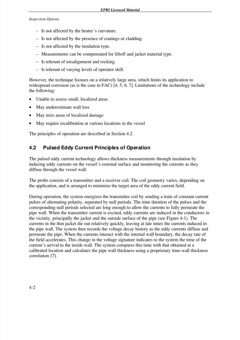
Figure 4-1Pulsed Eddy Current Field Representation
Because the eddy currents expand as they diffuse into the pipe wall, the footprint of the sensingfield is relatively large. The Incotest system focuses the field by designing the transmitter and
receiver coils with multiple loops to induce opposing currents that cancel the outer portion of theeddy current field. These loop designs change, depending on the geometry of the component.
Aptech provides two sensors: Probes P1.5-04 and V1.0-02. The Probe V1.0-02 has a morefocused target area but has limited wall thickness penetration and is recommended for piping
applications. The Model P1.5-04, commonly used in feedwater heater examinations, has afootprint of about 8 inches (203.2 mm) in diameter at a liftoff of 3 inches (76.2 mm) and iscurrently the preferred probe for vessel examinations [8]. This sensor is shown in Figure 4-2.
7/26/2019 In-Service Feed water Heater Condition Assessment Using the Pulsed Eddy Current NDE Technology.pdf
http://slidepdf.com/reader/full/in-service-feed-water-heater-condition-assessment-using-the-pulsed-eddy-current 30/68
EPRI Licensed Material
Inspection Options
4-4
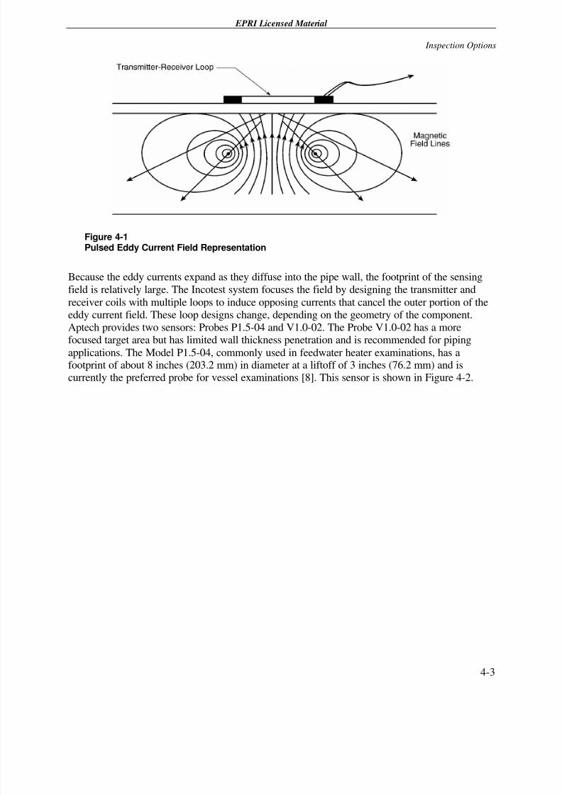
Figure 4-2
PEC Operator Placing the Pulsed Eddy Current Sensor on the Feedwater Heater Insulation
4.3 Pulsed Eddy Current Field Operation
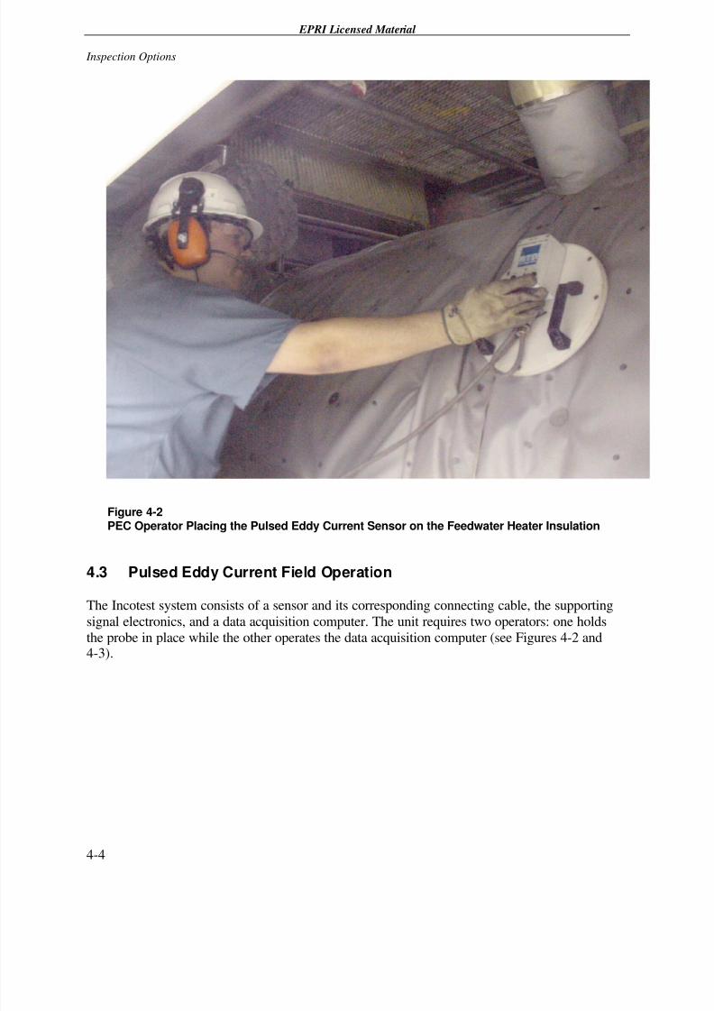
The Incotest system consists of a sensor and its corresponding connecting cable, the supporting
signal electronics, and a data acquisition computer. The unit requires two operators: one holds
the probe in place while the other operates the data acquisition computer (see Figures 4-2 and4-3).
7/26/2019 In-Service Feed water Heater Condition Assessment Using the Pulsed Eddy Current NDE Technology.pdf
http://slidepdf.com/reader/full/in-service-feed-water-heater-condition-assessment-using-the-pulsed-eddy-current 31/68
EPRI Licensed Material
Inspection Options
4-5
Figure 4-3
PEC Operator Running the Data Acquisition System
It is recommended that a grid be established over the examination area of interest, with the grid
insulation painted at a spacing of 6 inches (152.4 mm) or less, as shown in Figure 4-2. Thicknessmeasurements are then performed at each grid node and labeled with letters in the
circumferential direction and with numbers in the axial direction. These coordinates are thentransported to a spreadsheet for reporting without modification.
At the start of the examination, the operator surveys a vessel location where the wall thickness
and liftoff are known. The software uses this information to set the reference wall thickness andcalculate the eddy current penetration time, sheeting delay, and liftoff voltage shift. The operator
then selects the appropriate time range and the gain setting of the instrument. Three gain settingsare available and are selected to maximize the strength of the acquired signal while avoiding
saturation of the voltage acquisition electronics. The gain selection is performed duringcalibration and cannot be changed after the survey starts. After the instrument is calibrated, theexamination can commence.
As one of the operators places the sensor at a selected grid location, the other operator signals the
instrument to energize the coil and acquire the data. The latter operator then observes the signals
7/26/2019 In-Service Feed water Heater Condition Assessment Using the Pulsed Eddy Current NDE Technology.pdf
http://slidepdf.com/reader/full/in-service-feed-water-heater-condition-assessment-using-the-pulsed-eddy-current 32/68
EPRI Licensed Material
Inspection Options
4-6
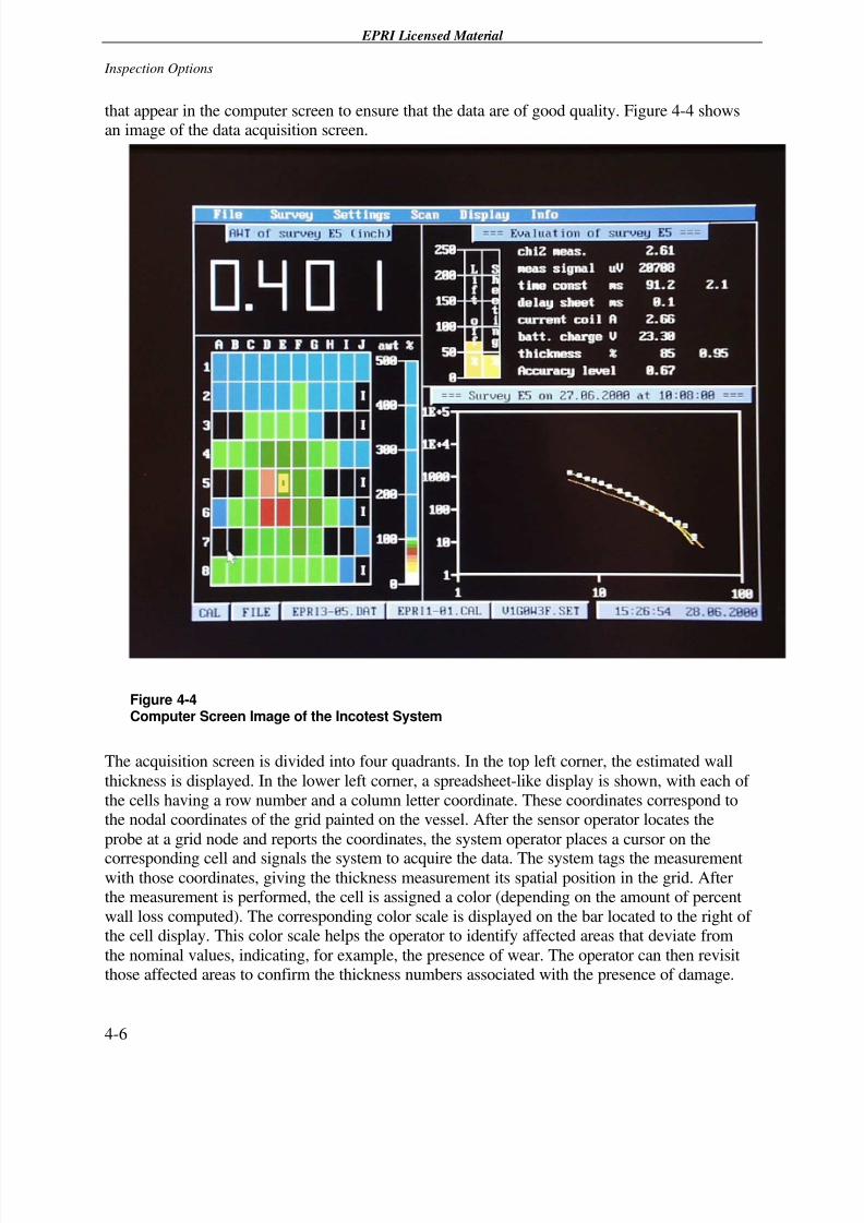
that appear in the computer screen to ensure that the data are of good quality. Figure 4-4 showsan image of the data acquisition screen.
Figure 4-4Computer Screen Image of the Incotest System
The acquisition screen is divided into four quadrants. In the top left corner, the estimated wall
thickness is displayed. In the lower left corner, a spreadsheet-like display is shown, with each of
the cells having a row number and a column letter coordinate. These coordinates correspond tothe nodal coordinates of the grid painted on the vessel. After the sensor operator locates the
probe at a grid node and reports the coordinates, the system operator places a cursor on the
corresponding cell and signals the system to acquire the data. The system tags the measurementwith those coordinates, giving the thickness measurement its spatial position in the grid. Afterthe measurement is performed, the cell is assigned a color (depending on the amount of percent
wall loss computed). The corresponding color scale is displayed on the bar located to the right of the cell display. This color scale helps the operator to identify affected areas that deviate from
the nominal values, indicating, for example, the presence of wear. The operator can then revisitthose affected areas to confirm the thickness numbers associated with the presence of damage.
7/26/2019 In-Service Feed water Heater Condition Assessment Using the Pulsed Eddy Current NDE Technology.pdf
http://slidepdf.com/reader/full/in-service-feed-water-heater-condition-assessment-using-the-pulsed-eddy-current 33/68
EPRI Licensed Material
Inspection Options
4-7
The upper right hand corner of the computer screen lists parameters used by the operator to
ensure the quality of the signal. These parameters assist the operator as follows:
• Chi2_meas. compares the acquired voltage decay with a model trace and computes its
deviation. Chi2 values of approximately 2 are considered satisfactory; values of 10 should berepeated.
• Meas_Signal_uV provides the operator with the voltage value at which the thickness
measurement is performed to assist the operator if the gain selection is correctly set.
• Time_ const_ms displays the constants used in the thickness correlation. These constants arecalculated during the calibration stage.
• Delay_sheet_ms displays the estimated time delay assigned to the sheeting or insulation
jacket. The operator tracks this parameter to monitor whether changes in the insulation jacket, such as jacket overlap, may affect the measurement.
• Current_coil_A displays the amperage delivered to the sensors and is used for monitoring theproper electrical continuity of the cable-sensor loop.
• Batt._charge_V provides a measurement of the battery voltage levels and advises the
operator when the batteries should be exchanged for fresh units.
• Thickness_% gives the thickness measurement as a percent of the reference wall thickness.
• Accuracy_level provides the operator with a confidence measure on the overall quality of themeasurement.
The upper right quadrant also includes two bar scales for liftoff and sheeting as a percent of the
values determined during calibration. These scales assist the operator in understanding whetherthe liftoff and sheeting conditions have deviated significantly from the reference location.
The lower right quadrant of the computer screen includes a voltage versus time chart with three
traces. Circles represent the acquired voltage history. The best-fit thickness model for the
acquired data is represented by a yellow trace. Finally, the voltage history obtained at thereference location is represented by a green trace. The traces assist the operator in tracking the
voltage decay to determine if it deviates significantly from the reference trace. If the surveyedlocation exhibits variations in the liftoff or sheeting, the entire acquired trace would shift from
the reference trace. If the surveyed location were thinner, the acquired trace would drop off relative to the reference trace at later times.
4.3.1 Adjustments to Calibration Shifts
The calibration of the pulsed eddy current technology is sensitive to changes in the material
properties of the steel, particularly changes in the steel’s electrical conductivity and magneticpermeability. Typically, the material properties remain fairly uniform within a given plate but
may change as the survey crosses over a weld into a different plate. Difficulty arises because thewelds are covered with insulation, hiding the transition between plates and causing the possiblechange in calibration.
7/26/2019 In-Service Feed water Heater Condition Assessment Using the Pulsed Eddy Current NDE Technology.pdf
http://slidepdf.com/reader/full/in-service-feed-water-heater-condition-assessment-using-the-pulsed-eddy-current 34/68
EPRI Licensed Material
Inspection Options
4-8
However, when a calibration shift occurs, the operator can recognize the change by noting the
variations in thickness over a large rectangular area. Normally, the change occurs along a straightline in the circumferential or axial direction.
Once calibration deviations are recognized, the operator typically will request that the utility
provide a new thickness reference value within the plate in question. The new thickness valueallows the calibration to be reset and acquired data to be adjusted using post-processing software.
4.3.2 Interpretation of Corrosion Indications
Aptech provides no guidelines for the interpretation of results. It limits its comments to
suggesting that all deviations of -20% or more shall be reported as potential corrosionindications, and the lowest reading shall be reported in a brief summary to the customer [8].
Significant indications can be recognized by an engineering review of the data presented in a
matrix of color-coded thickness patterns. The operator also has the option of interrogating the
data using the RTD-Incotest “defect mode” to help discriminate small areas of wall loss. Becausethe footprint of the measurement extends over a circle approximately 8 inches (203.2 mm) in
diameter, indications are identified as thickness losses that include several neighboring nodes.Furthermore, because the instrument averages the wall thickness over the footprint, the thicknesssafety factor is less conservative than in ultrasonic measurements.
Accordingly, corrosion indications are identified when the survey detects a wall thickness
reduction of more than 10% of the baseline value over several neighboring nodes. The baseline
thickness value is estimated from the nodes that surround the affected area and may approximatethe shell nominal wall thickness, or it may be substantially shifted from the nominal value if acalibration shift has occurred.
7/26/2019 In-Service Feed water Heater Condition Assessment Using the Pulsed Eddy Current NDE Technology.pdf
http://slidepdf.com/reader/full/in-service-feed-water-heater-condition-assessment-using-the-pulsed-eddy-current 35/68
EPRI Licensed Material
5-1
5 PULSED EDDY CURRENT FIELD EVALUATION
The objective of the evaluation program was to estimate the effectiveness of the pulsed eddy
current technology to assess the shell condition when surveying through insulation. In principle,
after a damage indication is reported, the heater would then be scheduled for detailed ultrasonicexamination during a forthcoming outage.
To achieve the objective, comparative data were obtained from six nuclear stations (five PWR
and one BWR). These pulsed eddy current examinations were performed on-line throughinsulation with a grid painted on the insulation jacket at a 6-inch (152.4-mm) spacing, as shown
in Figure 4-2. The utility later followed up these examinations by removing the insulation andperforming a detailed ultrasonic survey over the same area, using a finer grid with either a 2- or3-inch (50.8- or 76.2-mm) spacing, as shown in Figure 5-1.
7/26/2019 In-Service Feed water Heater Condition Assessment Using the Pulsed Eddy Current NDE Technology.pdf
http://slidepdf.com/reader/full/in-service-feed-water-heater-condition-assessment-using-the-pulsed-eddy-current 36/68
EPRI Licensed Material
Pulsed Eddy Current Field Evaluation
5-2
Figure 5-1Feedwater Heater Vessel with the Insulation Removed near the Steam Extraction InletNozzle and Grinded for Ultrasonic Examination
Of the six nuclear stations surveyed, four found erosion in the examined feedwater heaters. At
the request of the contributing utilities, the plant names were omitted and replaced by the lettersA (the BWR plant) and B, C, and D (PWR plants).
To facilitate the comparison between pulsed eddy current and ultrasonics, the data were
processed using a contouring software program called 3D-Field. This software uses a
mathematical algorithm to represent as a colored topographic map the thickness data taken over agrid.
Furthermore, the vessel data were split along the nozzle plane into a left and right side map. As
shown in Figure 3-1, the erosion damage typically appears in pairs on each side of the nozzle.Splitting the data simplifies the comparison for each morphology.
Finally, the pulsed eddy current and pulse echo ultrasonic maps were presented side-by-side with
the same scale. This presentation permits qualitative and quantitative comparisons. As mentioned

7/26/2019 In-Service Feed water Heater Condition Assessment Using the Pulsed Eddy Current NDE Technology.pdf
http://slidepdf.com/reader/full/in-service-feed-water-heater-condition-assessment-using-the-pulsed-eddy-current 37/68
EPRI Licensed Material
Pulsed Eddy Current Field Evaluation
5-3
in Section 3.2, the areal erosion extent tends to have an ellipsoidal shape. The maps allowvisualizing if the corrosion patterns are in close agreement.
The results of the evaluations are presented in Figures 5-2 through 5-19.
7/26/2019 In-Service Feed water Heater Condition Assessment Using the Pulsed Eddy Current NDE Technology.pdf
http://slidepdf.com/reader/full/in-service-feed-water-heater-condition-assessment-using-the-pulsed-eddy-current 38/68
E P R I L i c e n s e d M a t e r i a l
P u l s e d E d d y C u r r e n t F i e l d E v a l u a t i o n
5 - 4
F i g u r e 5 - 2
C o m p a r i s o n o f U l t r a
s o n i c s a n d P u l s e d E d d y C u r r e n
t E x a m i n a t i o n R e s u l t s f o r P l a n t A F e e d w a t e r H e a t e r S h e l l 3 A – L e f t S e c t i o n
7/26/2019 In-Service Feed water Heater Condition Assessment Using the Pulsed Eddy Current NDE Technology.pdf
http://slidepdf.com/reader/full/in-service-feed-water-heater-condition-assessment-using-the-pulsed-eddy-current 39/68
E P R I L i c e n s e d M a t e r i a l
P u l s e d E d d y C u r r e
n t F i e l d E v a l u a t i o n
5 - 5
F i g u r e 5 - 3
C o m p a r i s o n o f U l t r a s o n i c s a n d P u l s e d E d d y C u r r e n
t E x a m i n a t i o n R e s u l t s f o r P l a n t A F e e d w a t e r H e a t e r S h e l l 3 A – R i g h t S e c t i o n
7/26/2019 In-Service Feed water Heater Condition Assessment Using the Pulsed Eddy Current NDE Technology.pdf
http://slidepdf.com/reader/full/in-service-feed-water-heater-condition-assessment-using-the-pulsed-eddy-current 40/68
E P R I L i c e n s e d M a t e r i a l
P u l s e d E d d y C u r r e n t F i e l d E v a l u a t i o n
5 - 6
F i g u r e 5 - 4
C o m p a r i s o n o f U l t r a s o n i c s a n d P u l s e d E d d y C u r r e n
t E x a m i n a t i o n R e s u l t s f o r P l a n t A F e e d w a t e r H e a t e r S h e l l 3 B – L e f t S e c t i o n
7/26/2019 In-Service Feed water Heater Condition Assessment Using the Pulsed Eddy Current NDE Technology.pdf
http://slidepdf.com/reader/full/in-service-feed-water-heater-condition-assessment-using-the-pulsed-eddy-current 41/68
E P R I L i c e n s e d M a t e r i a l
P u l s e d E d d y C u r r e
n t F i e l d E v a l u a t i o n
5 - 7
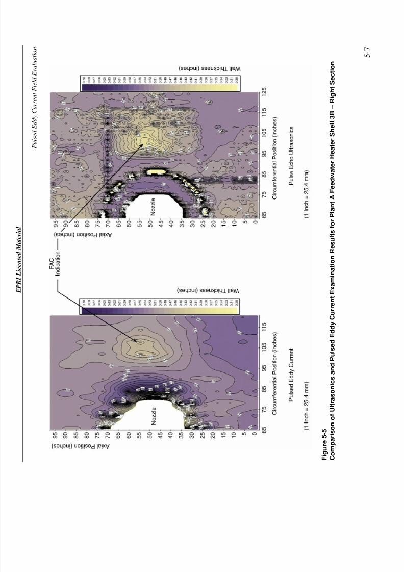
F i g u r e 5 - 5
C o m p a r i s o n o f U l t r a s o n i c s a n d P u l s e d E d d y C u r r e n
t E x a m i n a t i o n R e s u l t s f o r P l a n t A F e e d w a t e r H e a t e r S h e l l 3 B – R i g h t S e c t i o n
7/26/2019 In-Service Feed water Heater Condition Assessment Using the Pulsed Eddy Current NDE Technology.pdf
http://slidepdf.com/reader/full/in-service-feed-water-heater-condition-assessment-using-the-pulsed-eddy-current 42/68
E P R I L i c e n s e d M a t e r i a l
P u l s e d E d d y C u r r e n t F i e l d E v a l u a t i o n
5 - 8
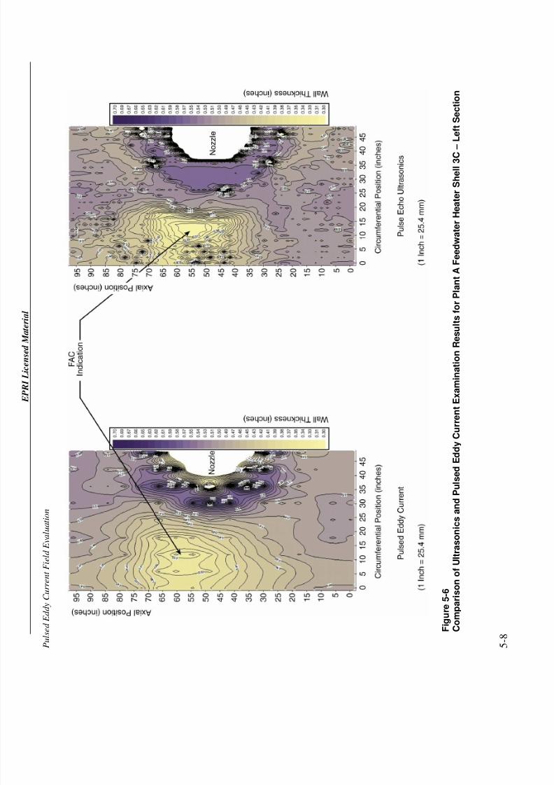
F i g u r e 5 - 6
C o m p a r i s o n o f U l t r a s o n i c s a n d P u l s e d E d d y C u r r e n
t E x a m i n a t i o n R e s u l t s f o r P l a n t A F e e d w a t e r H e a t e r S h e l l 3 C – L e f t S e c t i o n
7/26/2019 In-Service Feed water Heater Condition Assessment Using the Pulsed Eddy Current NDE Technology.pdf
http://slidepdf.com/reader/full/in-service-feed-water-heater-condition-assessment-using-the-pulsed-eddy-current 43/68
E P R I L i c e n s e d M a t e r i a l
P u l s e d E d d y C u r r e
n t F i e l d E v a l u a t i o n
5 - 9
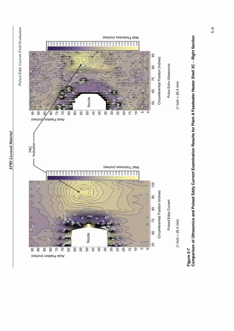
F i g u r e 5 - 7
C o m p a r i s o n o f U l t r a s o n i c s a n d P u l s e d E d d y C u r r e n
t E x a m i n a t i o n R e s u l t s f o r P l a n t A F e e d w a t e r H e a t e r S h e l l 3 C – R i g h t S e c t i o n
7/26/2019 In-Service Feed water Heater Condition Assessment Using the Pulsed Eddy Current NDE Technology.pdf
http://slidepdf.com/reader/full/in-service-feed-water-heater-condition-assessment-using-the-pulsed-eddy-current 44/68
E P R I L i c e n s e d M a t e r i a l
P u l s e d E d d y C u r r e n t F i e l d E v a l u a t i o n
5 - 1 0 F
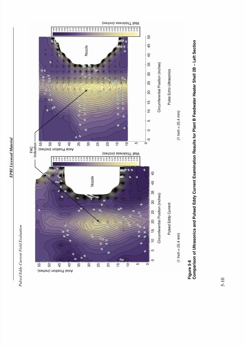
i g u r e 5 - 8
C o m p a r i s o n o f U l t r a s o n i c s a n d P u l s e d E d d y C u r r e n
t E x a m i n a t i o n R e s u l t s f o r P l a n t B F e e d w a t e r H e a t e r S h e l l 2 B – L e f t S e c t i o n
7/26/2019 In-Service Feed water Heater Condition Assessment Using the Pulsed Eddy Current NDE Technology.pdf
http://slidepdf.com/reader/full/in-service-feed-water-heater-condition-assessment-using-the-pulsed-eddy-current 45/68
E P R I L i c e n s e d M a t e r i a l
P u l s e d E d d y C u r r e
n t F i e l d E v a l u a t i o n
5 - 1 1
F i g u r e 5 - 9
C o m p a r i s o n o f U l t r a s o n i c s a n d P u l s e d E d d y C u r r e n
t E x a m i n a t i o n R e s u l t s f o r P l a n t B F e e d w a t e r H e a t e r S h e l l 2 B – R i g h t S e c t i o n
7/26/2019 In-Service Feed water Heater Condition Assessment Using the Pulsed Eddy Current NDE Technology.pdf
http://slidepdf.com/reader/full/in-service-feed-water-heater-condition-assessment-using-the-pulsed-eddy-current 46/68
E P R I L i c e n s e d M a t e r i a l
P u l s e d E d d y C u r r e n t F i e l d E v a l u a t i o n
5 - 1 2 F
i g u r e 5 - 1 0
C o m p a r i s o n o f U l t r a s o n i c s a n d P u l s e d E d d y C u r r e n
t E x a m i n a t i o n R e s u l t s f o r P l a n t B F e e d w a t e r H e a t e r S h e l l 4 B – L e f t S e c t i o n
7/26/2019 In-Service Feed water Heater Condition Assessment Using the Pulsed Eddy Current NDE Technology.pdf
http://slidepdf.com/reader/full/in-service-feed-water-heater-condition-assessment-using-the-pulsed-eddy-current 47/68
E P R I L i c e n s e d M a t e r i a l
P u l s e d E d d y C u r r e
n t F i e l d E v a l u a t i o n
5 - 1 3
F i g u r e 5 - 1 1
C o m p a r i s o n o f U l t r a s o n i c s a n d P u l s e d E d d y C u r r e n
t E x a m i n a t i o n R e s u l t s f o r P W R P l a n t D F e e d w a t e r H e a t e r
S h e l l 5 B – L e f t S e c t i o n
7/26/2019 In-Service Feed water Heater Condition Assessment Using the Pulsed Eddy Current NDE Technology.pdf
http://slidepdf.com/reader/full/in-service-feed-water-heater-condition-assessment-using-the-pulsed-eddy-current 48/68
E P R I L i c e n s e d M a t e r i a l
P u l s e d E d d y C u r r e n t F i e l d E v a l u a t i o n
5 - 1 4 F
i g u r e 5 - 1 2
C o m p a r i s o n o f U l t r a s o n i c s a n d P u l s e d E d d y C u r r e n
t E x a m i n a t i o n R e s u l t s f o r P l a n t B F e e d w a t e r H e a t e r S h e l l 4 B – R i g h t S e c t i o n
7/26/2019 In-Service Feed water Heater Condition Assessment Using the Pulsed Eddy Current NDE Technology.pdf
http://slidepdf.com/reader/full/in-service-feed-water-heater-condition-assessment-using-the-pulsed-eddy-current 49/68
E P R I L i c e n s e d M a t e r i a l
P u l s e d E d d y C u r r e
n t F i e l d E v a l u a t i o n
5 - 1 5
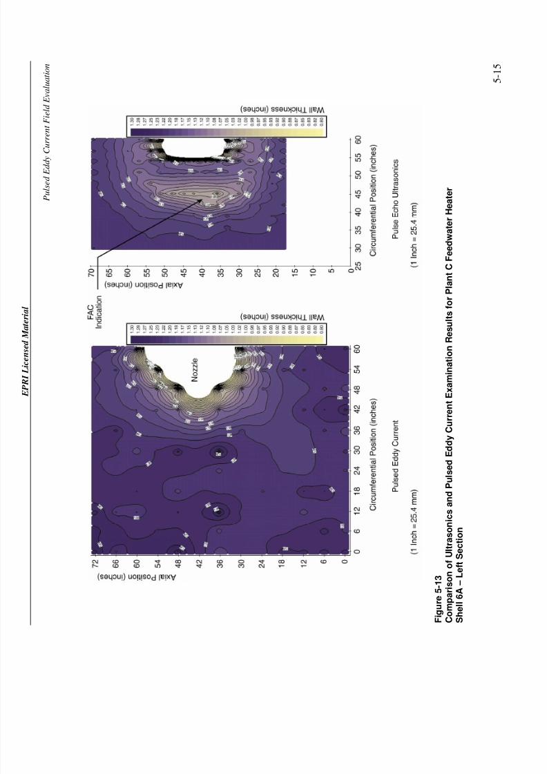
F i g u r e 5 - 1 3
C o m p a r i s o n o f U l t r a s o n i c s a n d P u l s e d E d d y C u r r e n
t E x a m i n a t i o n R e s u l t s f o r P l a n t C F e e d w a t e r H e a t e r
S h e l l 6 A – L e f t S e c t i o n
7/26/2019 In-Service Feed water Heater Condition Assessment Using the Pulsed Eddy Current NDE Technology.pdf
http://slidepdf.com/reader/full/in-service-feed-water-heater-condition-assessment-using-the-pulsed-eddy-current 50/68
E P R I L i c e n s e d M a t e r i a l
P u l s e d E d d y C u r r e n t F i e l d E v a l u a t i o n
5 - 1 6 F
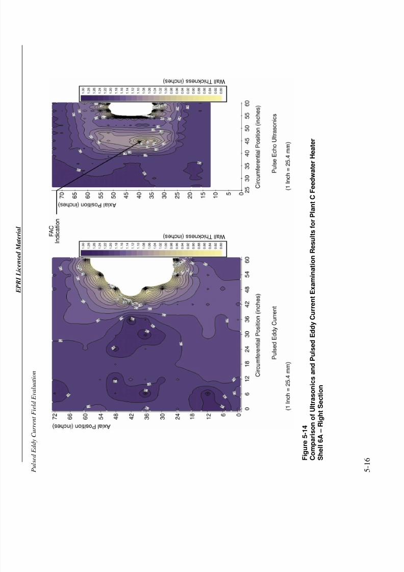
i g u r e 5 - 1 4
C o m p a r i s o n o f U l t r a s o n i c s a n d P u l s e d E d d y C u r r e n
t E x a m i n a t i o n R e s u l t s f o r P l a n t C F e e d w a t e r H e a t e r
S h e l l 6 A – R i g h t S e c t i o n

7/26/2019 In-Service Feed water Heater Condition Assessment Using the Pulsed Eddy Current NDE Technology.pdf
http://slidepdf.com/reader/full/in-service-feed-water-heater-condition-assessment-using-the-pulsed-eddy-current 51/68
E P R I L i c e n s e d M a t e r i a l
P u l s e d E d d y C u r r e
n t F i e l d E v a l u a t i o n
5 - 1 7
F i g u r e 5 - 1 5
C o m p a r i s o n o f U l t r a s o n i c s a n d P u l s e d E d d y C u r r e n
t E x a m i n a t i o n R e s u l t s f o r P l a n t C F e e d w a t e r H e a t e r
S h e l l 6 B – L e f t S e c t i o n
7/26/2019 In-Service Feed water Heater Condition Assessment Using the Pulsed Eddy Current NDE Technology.pdf
http://slidepdf.com/reader/full/in-service-feed-water-heater-condition-assessment-using-the-pulsed-eddy-current 52/68
E P R I L i c e n s e d M a t e r i a l
P u l s e d E d d y C u r r e n t F i e l d E v a l u a t i o n
5 - 1 8 F
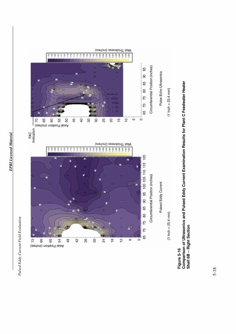
i g u r e 5 - 1 6
C o m p a r i s o n o f U l t r a s o n i c s a n d P u l s e d E d d y C u r r e n
t E x a m i n a t i o n R e s u l t s f o r P l a n t C F e e d w a t e r H e a t e r
S h e l l 6 B – R i g h t S e c t i o n
7/26/2019 In-Service Feed water Heater Condition Assessment Using the Pulsed Eddy Current NDE Technology.pdf
http://slidepdf.com/reader/full/in-service-feed-water-heater-condition-assessment-using-the-pulsed-eddy-current 53/68
E P R I L i c e n s e d M a t e r i a l
P u l s e d E d d y C u r r e
n t F i e l d E v a l u a t i o n
5 - 1 9
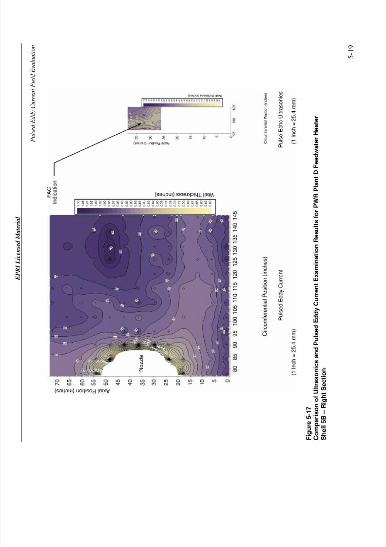
F i g u r e 5 - 1 7
C o m p a r i s o n o f U l t r a s o n i c s a n d P u l s e d E d d y C u r r e n
t E x a m i n a t i o n R e s u l t s f o r P W R P l a n t D F e e d w a t e r H e a t e r
S h e l l 5 B – R i g h t S e c t i o n
7/26/2019 In-Service Feed water Heater Condition Assessment Using the Pulsed Eddy Current NDE Technology.pdf
http://slidepdf.com/reader/full/in-service-feed-water-heater-condition-assessment-using-the-pulsed-eddy-current 54/68
EPRI Licensed Material
Pulsed Eddy Current Field Evaluation
5-20
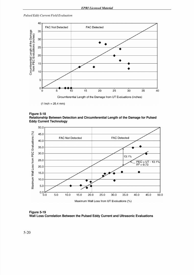
Figure 5-18Relationship Between Detection and Circumferential Length of the Damage for PulsedEddy Current Technology
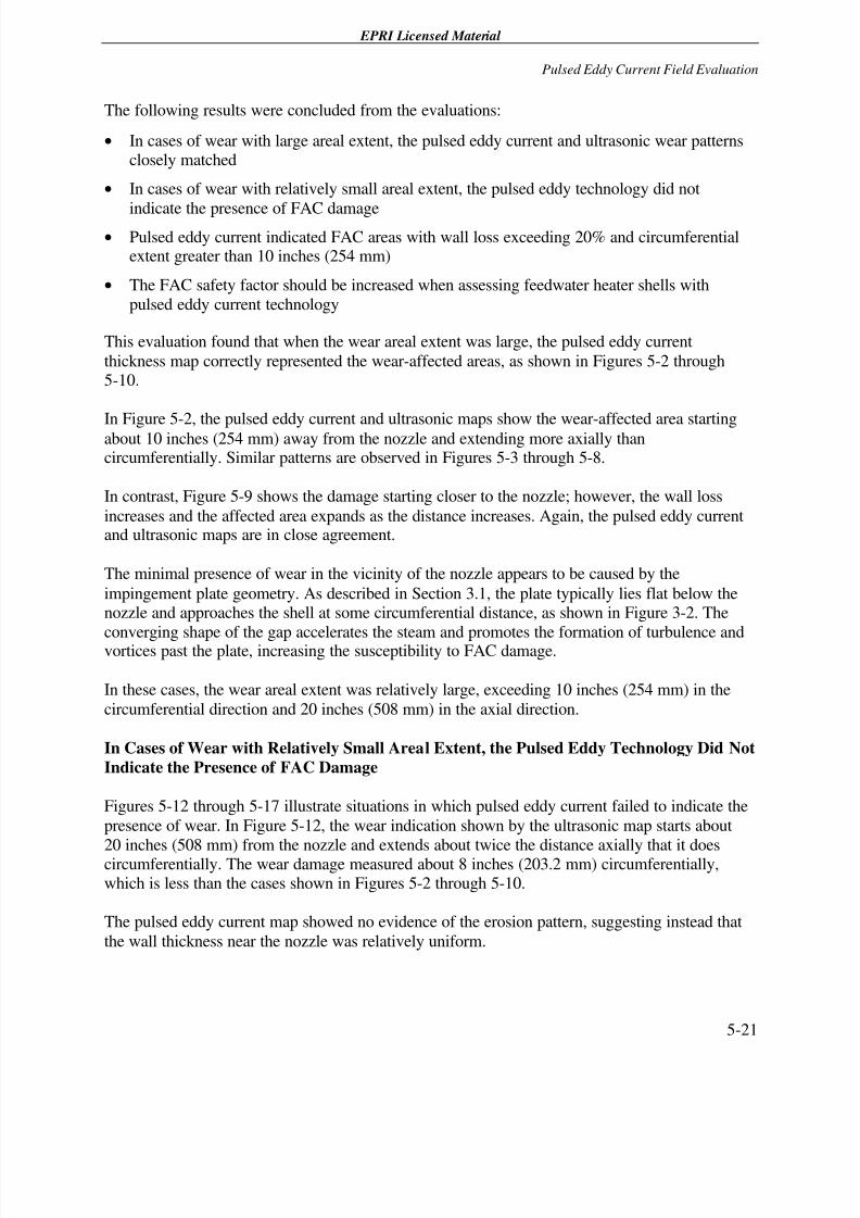
Figure 5-19Wall Loss Correlation Between the Pulsed Eddy Current and Ultrasonic Evaluations
7/26/2019 In-Service Feed water Heater Condition Assessment Using the Pulsed Eddy Current NDE Technology.pdf
http://slidepdf.com/reader/full/in-service-feed-water-heater-condition-assessment-using-the-pulsed-eddy-current 55/68
EPRI Licensed Material
Pulsed Eddy Current Field Evaluation
5-21
The following results were concluded from the evaluations:
• In cases of wear with large areal extent, the pulsed eddy current and ultrasonic wear patternsclosely matched
• In cases of wear with relatively small areal extent, the pulsed eddy technology did not
indicate the presence of FAC damage• Pulsed eddy current indicated FAC areas with wall loss exceeding 20% and circumferential
extent greater than 10 inches (254 mm)
• The FAC safety factor should be increased when assessing feedwater heater shells with
pulsed eddy current technology
This evaluation found that when the wear areal extent was large, the pulsed eddy current
thickness map correctly represented the wear-affected areas, as shown in Figures 5-2 through5-10.
In Figure 5-2, the pulsed eddy current and ultrasonic maps show the wear-affected area startingabout 10 inches (254 mm) away from the nozzle and extending more axially thancircumferentially. Similar patterns are observed in Figures 5-3 through 5-8.
In contrast, Figure 5-9 shows the damage starting closer to the nozzle; however, the wall loss
increases and the affected area expands as the distance increases. Again, the pulsed eddy currentand ultrasonic maps are in close agreement.
The minimal presence of wear in the vicinity of the nozzle appears to be caused by the
impingement plate geometry. As described in Section 3.1, the plate typically lies flat below thenozzle and approaches the shell at some circumferential distance, as shown in Figure 3-2. The
converging shape of the gap accelerates the steam and promotes the formation of turbulence andvortices past the plate, increasing the susceptibility to FAC damage.
In these cases, the wear areal extent was relatively large, exceeding 10 inches (254 mm) in the
circumferential direction and 20 inches (508 mm) in the axial direction.
In Cases of Wear with Relatively Small Areal Extent, the Pulsed Eddy Technology Did Not
Indicate the Presence of FAC Damage
Figures 5-12 through 5-17 illustrate situations in which pulsed eddy current failed to indicate the
presence of wear. In Figure 5-12, the wear indication shown by the ultrasonic map starts about
20 inches (508 mm) from the nozzle and extends about twice the distance axially that it doescircumferentially. The wear damage measured about 8 inches (203.2 mm) circumferentially,which is less than the cases shown in Figures 5-2 through 5-10.
The pulsed eddy current map showed no evidence of the erosion pattern, suggesting instead that
the wall thickness near the nozzle was relatively uniform.
7/26/2019 In-Service Feed water Heater Condition Assessment Using the Pulsed Eddy Current NDE Technology.pdf
http://slidepdf.com/reader/full/in-service-feed-water-heater-condition-assessment-using-the-pulsed-eddy-current 56/68
EPRI Licensed Material
Pulsed Eddy Current Field Evaluation
5-22
Lack of wear indication combined with relatively small areal extent is repeated in Figures 5-13
though 5-16. In fact, in Figures 5-15 and 5-16, pulsed eddy current indicates wall thicknessesthat appear to be thicker in the areas affected by erosion. In the heater shown in Figures 5-15 and
5-16, the tube support plate was located directly under the steam extraction inlet nozzle, whichmay have contributed to the apparent lack of correlation.
Figure 5-17 provides another example of a lack of wear indications by the pulsed eddy current
survey. In this case, the utility minimized the size of the ultrasonic grid, having enough coverageto detect the FAC damage but not sufficient to determine its areal extent.
These results suggest that the application of pulsed eddy current technology in its current state of
development is not optimized to detect wear areas with relatively small areal extent.
Pulsed Eddy Current Indicated FAC Areas with Wall Loss Exceeding 20% and
Circumferential Extent Greater Than 10 inches (254 mm)
The results thus far indicate that wear detection with the pulsed eddy current technology dependson the wall loss and the areal extent.
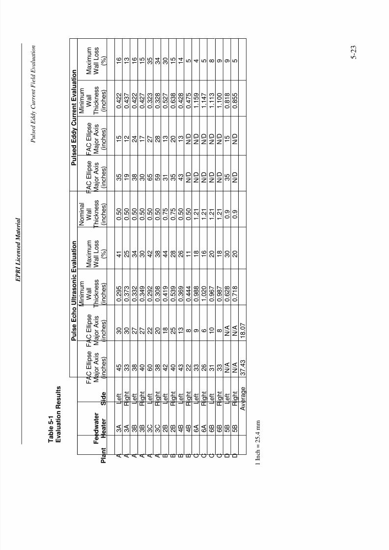
To identify how wall loss and areal extent are interrelated, the circumferential and axial lengths
of the wear-affected areas were extracted from the topographic maps shown in Figures 5-2through 5-17 along with the maximum percent wall loss. Table 5-1 lists these results.
7/26/2019 In-Service Feed water Heater Condition Assessment Using the Pulsed Eddy Current NDE Technology.pdf
http://slidepdf.com/reader/full/in-service-feed-water-heater-condition-assessment-using-the-pulsed-eddy-current 57/68
E P R I L i c e n s e d M a t e r i a l
P u l s e d E d d y C u r r e
n t F i e l d E v a l u a t i o n
5 - 2 3
T a b l e 5 - 1
E v a l u a t i o n R e s u l t s
P u l s e E c h o U l t r a s
o n i c E v a l u a t i o n
P u l s e d E d d y C u r r e n t E v
a l u a t i o n
P l a n t
F e e d w a t e r
H e a t e r
S i d e
F A C E l l i p s e
M a
j o r
A x
i s
( i n c
h e s )
F A C E l l i p s e
M a
j o r
A x
i s
( i n c
h e s )
M i n i m u
m
W a l l
T h i c k n e
s s
( i n c h e s )
M a x
i m u m
W a
l l L o s s
( % )
N o m
i n a
l
W a
l l
T h i c k n e s s
( i n c
h e s
) F
A C E l l i p s e
M a
j o r
A x
i s
( i n c
h e s )
F A C E l l i p s e
M a
j o r
A x
i s
( i n c
h e s
)
M i n i m u
m
W a l
l
T h i c k n e s s
( i n c h e
s )
M a x
i m u m
W a
l l L o s s
( % )
A
3 A
L e
f t
4 5
3 0
0 . 2 9 5
4 1
0 . 5
0
3 5
1 5
0 . 4 2 2
1 6
A
3 A
R i g h t
3 3
3 0
0 . 3 7 3
2 5
0 . 5
0
1 9
1 2
0 . 4 3 7
1 3
A
3 B
L e
f t
3 8
2 7
0 . 3 3 2
3 4
0 . 5
0
3 8
2 4
0 . 4 2 2
1 6
A
3 B
R i g h t
4 0
2 7
0 . 3 4 9
3 0
0 . 5
0
3 0
1 7
0 . 4 2 7
1 5
A
3 C
L e
f t
6 0
2 2
0 . 2 9 2
4 2
0 . 5
0
6 5
2 7
0 . 3 2 3
3 5
A
3 C
R i g h t
3 8
2 0
0 . 3 0 8
3 8
0 . 5
0
5 9
2 8
0 . 3 2 8
3 4
B
2 B
L e
f t
4 2
1 8
0 . 4 1 9
4 4
0 . 7
5
3 1
1 3
0 . 5 2 7
3 0
B
2 B
R i g h t
4 0
2 5
0 . 5 3 9
2 8
0 . 7
5
3 5
2 0
0 . 6 3 8
1 5
B
4 B
L e
f t
4 3
1 3
0 . 3 6 9
2 6
0 . 5
0
4 3
1 3
0 . 4 2 8
1 4
B
4 B
R i g h t
2 2
8
0 . 4 4 4
1 1
0 . 5
0
N / D
N / D
0 . 4 7 5
5
C
6 A
L e
f t
3 3
9
0 . 9 8 8
1 8
1 . 2
1
N / D
N / D
1 . 1 5 9
4
C
6 A
R i g h t
2 6
6
1 . 0 2 0
1 6
1 . 2
1
N / D
N / D
1 . 1 4 7
5
C
6 B
L e
f t
3 1
1 0
0 . 9 6 7
2 0
1 . 2
1
N / D
N / D
1 . 1 1 3
8
C
6 B
R i g h t
3 3
8
0 . 9 8 7
1 8
1 . 2
1
N / D
N / D
1 . 1 0 0
9
D
5 B
L e
f t
N / A
N / A
0 . 6 2 8
3 0
0 . 9
3 5
1 5
0 . 8 1 8
9
D
5 B
R i g h t
N / A
N / A
0 . 7 1 8
2 0
0 . 9
N / D
N / D
0 . 8 5 5
5
A v e r a g e
3 7
. 4 3
1 8
. 0 7
1 I n c h = 2 5 . 4 m m
7/26/2019 In-Service Feed water Heater Condition Assessment Using the Pulsed Eddy Current NDE Technology.pdf
http://slidepdf.com/reader/full/in-service-feed-water-heater-condition-assessment-using-the-pulsed-eddy-current 58/68
EPRI Licensed Material
Pulsed Eddy Current Field Evaluation
5-24
The data contained in the table confirm that the wear damage exhibits an axially elongated shapewith an average 2:1 ratio of axial to circumferential lengths.
The data also suggest a well-marked transition for detecting the effectiveness of the pulsed eddy
current technology. Note that when the circumferential extent of the wear-affected area was
greater than 10 inches (254 mm), pulsed eddy current reliably indicated the extent of the damage.However, for distances less than 10 inches (254 mm), the pulsed eddy current survey did not flag
the presence of FAC. These trends are graphically illustrated in Figure 5-18. In this figure,circumferential extents obtained from the ultrasonic maps are plotted against the values extracted
from the pulsed eddy current maps. Figure 5-18 shows that pulsed eddy current dataunderestimated the areal extent for lengths greater than 10 inches (254 mm) and failed to reportthe damage for lengths less than 10 inches (254 mm).
To understand the effectiveness of the pulsed eddy current technique for estimating the
maximum wall loss, the pulsed eddy current estimate was plotted against the ultrasonic value as
shown in Figure 5-19. The figure shows that the pulsed eddy current readings undersized the
wall loss by an average of 13%.
Figure 5-19 also shows that the pulsed eddy current detection limit coincides with a maximum
wall loss of 20%. Note further that at a wall loss of 20%, the corresponding pulsed eddy currentvalues range between 5 and 10% and, because of their low value, the wear patterns are likely to
be blurred. Therefore, Figure 5-19 shows that for small areal extents that exhibit wall losses lessthan 20%, the measured thickness changes are likely to remain within the measurement noiseand, accordingly, do not reliably indicate the presence of erosion.
The FAC Safety Factor Should Be Increased when Assessing Feedwater Heater Shells with
Pulsed Eddy Current Technology
The results indicate that the safety factor should be increased when estimating the shell life withpulsed eddy current data.
Life estimation is important for corrosion management because it affects the operational
acceptance of the heater and influences the repair plans. A utility needs to know 1) if the shellcan withstand the maximum operating pressure until the next scheduled outage and 2) when theshell may need to be repaired.
The shell is judged to be suitable for continued service if the predicted wall thickness at the time
of the next planned inspection is greater than the minimum accepted value [3], in accordance
with the formula:
Wall predicted = wall – (Wear Rate x Time-Next-Inspection x Safety Factor)
Eq. 5-1

7/26/2019 In-Service Feed water Heater Condition Assessment Using the Pulsed Eddy Current NDE Technology.pdf
http://slidepdf.com/reader/full/in-service-feed-water-heater-condition-assessment-using-the-pulsed-eddy-current 59/68
EPRI Licensed Material
Pulsed Eddy Current Field Evaluation
5-25
Likewise, a component is considered to have a given remaining useful life, in accordance with
the formula:
Life = (Wall – Minimum Acceptable Thickness) / (Wear Rate x Safety Factor)
Eq. 5-2
As seen in Figure 5-19, the pulsed eddy current wall loss assessment undersized the
corresponding ultrasonic values by 13%. This suggests that, when vessel life is assessed using
pulsed eddy current data, the safety factors shown in Equations 5-1 and 5-2 should be increasedto reflect the likely presence of a wall loss greater than otherwise reported.

7/26/2019 In-Service Feed water Heater Condition Assessment Using the Pulsed Eddy Current NDE Technology.pdf
http://slidepdf.com/reader/full/in-service-feed-water-heater-condition-assessment-using-the-pulsed-eddy-current 60/68
7/26/2019 In-Service Feed water Heater Condition Assessment Using the Pulsed Eddy Current NDE Technology.pdf
http://slidepdf.com/reader/full/in-service-feed-water-heater-condition-assessment-using-the-pulsed-eddy-current 61/68
EPRI Licensed Material
6-1
6 DISCUSSION
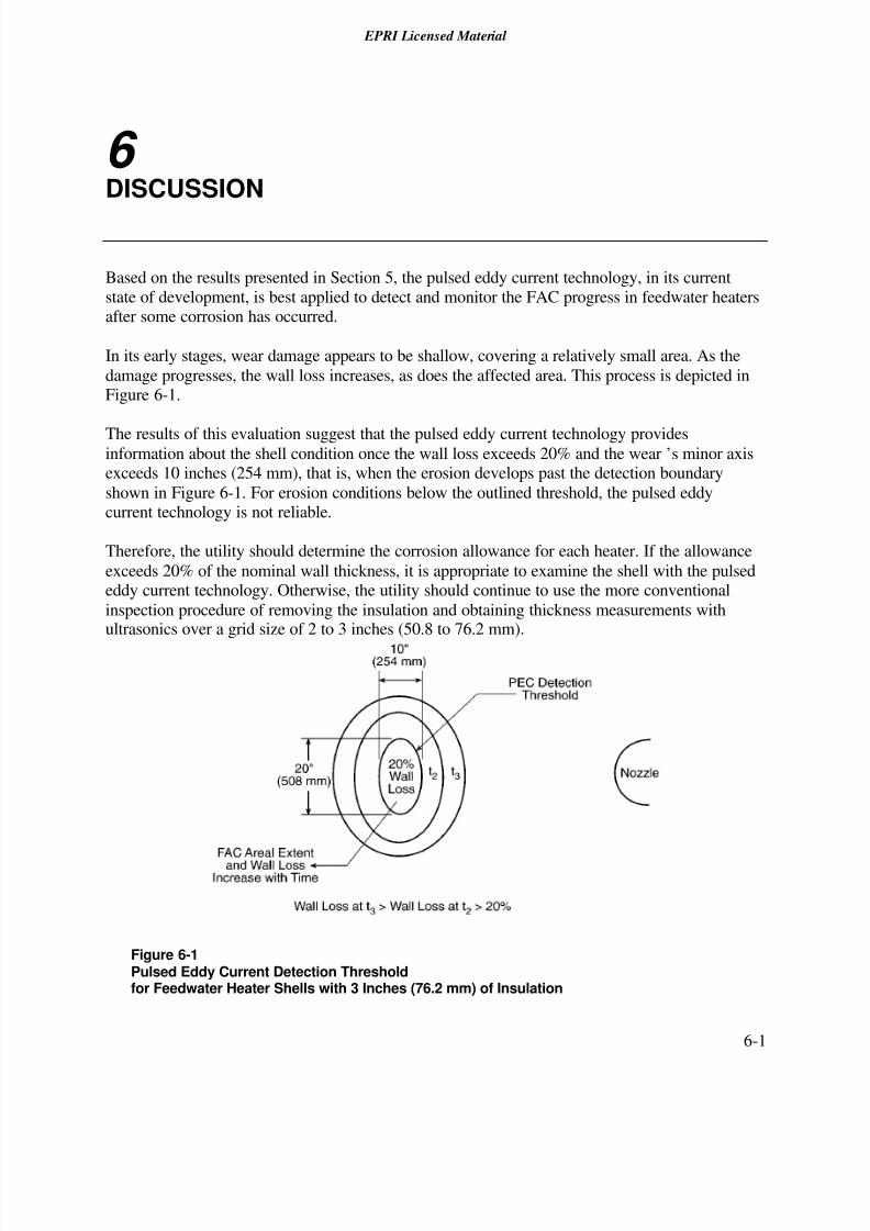
Based on the results presented in Section 5, the pulsed eddy current technology, in its current
state of development, is best applied to detect and monitor the FAC progress in feedwater heatersafter some corrosion has occurred.
In its early stages, wear damage appears to be shallow, covering a relatively small area. As the
damage progresses, the wall loss increases, as does the affected area. This process is depicted inFigure 6-1.
The results of this evaluation suggest that the pulsed eddy current technology providesinformation about the shell condition once the wall loss exceeds 20% and the wear’s minor axisexceeds 10 inches (254 mm), that is, when the erosion develops past the detection boundary
shown in Figure 6-1. For erosion conditions below the outlined threshold, the pulsed eddycurrent technology is not reliable.
Therefore, the utility should determine the corrosion allowance for each heater. If the allowance
exceeds 20% of the nominal wall thickness, it is appropriate to examine the shell with the pulsededdy current technology. Otherwise, the utility should continue to use the more conventional
inspection procedure of removing the insulation and obtaining thickness measurements withultrasonics over a grid size of 2 to 3 inches (50.8 to 76.2 mm).
Figure 6-1Pulsed Eddy Current Detection Thresholdfor Feedwater Heater Shells with 3 Inches (76.2 mm) of Insulation

7/26/2019 In-Service Feed water Heater Condition Assessment Using the Pulsed Eddy Current NDE Technology.pdf
http://slidepdf.com/reader/full/in-service-feed-water-heater-condition-assessment-using-the-pulsed-eddy-current 62/68
7/26/2019 In-Service Feed water Heater Condition Assessment Using the Pulsed Eddy Current NDE Technology.pdf
http://slidepdf.com/reader/full/in-service-feed-water-heater-condition-assessment-using-the-pulsed-eddy-current 63/68
EPRI Licensed Material
7-1
7 CONCLUSIONS
Based on the results obtained in this evaluation, the following were concluded:
• In cases of wear with large areal extent, the pulsed eddy current and ultrasonic wear patternsclosely matched
• In cases of wear with relatively small areal extent, the pulsed eddy current technology did notreliably indicate the presence of FAC damage
• Pulsed eddy current provided reliable detection of wear areas with wall loss exceeding 20%
and circumferential extent greater than 10 inches (254 mm)• The FAC safety factor should be increased when assessing feedwater heater shells with
pulsed eddy current technology
It is recommended that in the current state of technology development, examination of feedwater
heaters with pulsed eddy current be limited to shells with corrosion allowance that exceeds 20%
of the nominal wall thickness. For heaters with a lesser corrosion margin, the utility should usethe more conventional examination procedure of removing insulation and performing ultrasonic
thickness measurements over a 2- to 3-inch (50.8- to 76.2-mm) grid. EPRI plans to work with thetechnology developer to reduce the pulsed eddy current examination footprint.

7/26/2019 In-Service Feed water Heater Condition Assessment Using the Pulsed Eddy Current NDE Technology.pdf
http://slidepdf.com/reader/full/in-service-feed-water-heater-condition-assessment-using-the-pulsed-eddy-current 64/68
7/26/2019 In-Service Feed water Heater Condition Assessment Using the Pulsed Eddy Current NDE Technology.pdf
http://slidepdf.com/reader/full/in-service-feed-water-heater-condition-assessment-using-the-pulsed-eddy-current 65/68
EPRI Licensed Material
8-1
8 REFERENCES
1. CHECWORKS™ Users Group (CHUG) Position Paper No. 4, “Recommendations for
Inspecting Feedwater Heater Shells for Flow-Accelerated Corrosion Damage,” EPRI,February 2000.
2. Flow-Accelerated Corrosion in Power Plants. EPRI, Palo Alto, CA: 1998. TR-106611-R1.
3. Recommendations for an Effective Flow-Accelerated Corrosion Program. EPRI, Palo Alto,
CA: 1999. NSAC-202L-R2.
4. P. F. Lara, “TEMP – An Innovative System to Measure the Wall Thickness of Pipes, Tanks,
and Vessels Through Insulation.” Paper presented at the ASNT Fall Conference in Boston,MA (September 1991).
5. Evaluation of the Transient Electromagnetic Probing (TEMP) System for Detection of Wall
Thinning Through Insulation. EPRI, Palo Alto, CA: 1992. TR-101680.
6. Assessment of the Pulsed Eddy Current Technique: Detecting Flow-Accelerated Corrosion in
Feedwater Piping. EPRI, Palo Alto, CA: 1997. TR-109146.
7. FAC Wear Rate Assessment Through Insulation. EPRI, Palo Alto, CA: 2000. 1000114.
8. Aptech Engineering Services, AES-ET-4, Revision 3, “Eddy Current Specification Standard
Examination of Thermally Insulated Pipes and Vessels.” October 2000.

7/26/2019 In-Service Feed water Heater Condition Assessment Using the Pulsed Eddy Current NDE Technology.pdf
http://slidepdf.com/reader/full/in-service-feed-water-heater-condition-assessment-using-the-pulsed-eddy-current 66/68

7/26/2019 In-Service Feed water Heater Condition Assessment Using the Pulsed Eddy Current NDE Technology.pdf
http://slidepdf.com/reader/full/in-service-feed-water-heater-condition-assessment-using-the-pulsed-eddy-current 67/68
7/26/2019 In-Service Feed water Heater Condition Assessment Using the Pulsed Eddy Current NDE Technology.pdf
http://slidepdf.com/reader/full/in-service-feed-water-heater-condition-assessment-using-the-pulsed-eddy-current 68/68
WARNING: This Document containsinformation classified under U.S. ExportControl regulations as restricted fromexport outside the United States. You
are under an obligation to ensure that you have alegal right to obtain access to this informationand to ensure that you obtain an export licenseprior to any re-export of this information. Specialrestrictions apply to access by anyone that is nota United States citizen or a Permanent UnitedStates resident. For further information regard-ing your obligations, please see the information
contained below in the section titled “ExportControl Restrictions.”
Program: 1006372
Nuclear Power
SINGLE USER LICENSE AGREEMENT
THIS IS A LEGALLY BINDING AGREEMENT BETWEEN YOU AND THE ELECTRIC POWERRESEARCH INSTITUTE, INC. (EPRI). PLEASE READ IT CAREFULLY BEFORE REMOVING THEWRAPPING MATERIAL.
BY OPENING THIS SEALED PACKAGE YOU ARE AGREEING TO THE TERMS OF THIS AGREEMENT. IF YOU DONOT AGREE TO THE TERMS OF THIS AGREEMENT, PROMPTLY RETURN THE UNOPENED PACKAGE TO EPRIAND THE PURCHASE PRICE WILL BE REFUNDED.
1. GRANT OF LICENSEEPRI grants you the nonexclusive and nontransferable right during the term of this agreement to use this packageonly for your own benefit and the benefit of your organization.This means that the following may use this package:(I) your company (at any site owned or operated by your company);(II) its subsidiaries or other related entities; and(III) a consultant to your company or related entities, if the consultant has entered into a contract agreeing not to
disclose the package outside of its organization or to use the package for its own benefit or the benefit of any partyother than your company.
This shrink-wrap license agreement is subordinate to the terms of the Master Utility License Agreement betweenmost U.S. EPRI member utilities and EPRI. Any EPRI member utility that does not have a Master Utility LicenseAgreement may get one on request.
2. COPYRIGHTThis package, including the information contained in it,is either licensed to EPRI or owned by EPRI and is protected byUnited States and international copyright laws.You may not,without the prior written permission of EPRI, reproduce,translate or modify this package, in any form, in whole or in part,or prepare any derivative work based on this package.
3. RESTRICTIONSYou may not rent, lease, license, disclose or give this package to any person or organization,or use the informationcontained in this package, for the benefit of any third party or for any purpose other than as specified above unlesssuch use is with the prior written permission of EPRI.You agree to take all reasonable steps to prevent unauthorizeddisclosure or use of this package. Except as specified above, this agreement does not grant you any right to patents,copyrights,trade secrets, trade names, trademarks or any other intellectual property, rights or licenses in respect of this package.
4.TERM A ND TERMINATIONThis license and this agreement are effective until terminated.You may terminate them at any time by destroying thispackage. EPRI has the right to terminate the license and this agreement immediately if you fail to comply with anyterm or condition of this agreement. Upon any termination you may destroy this package, but all obligations of nondisclosure will remain in effect.
5. DISCLAIMER OF WARRANTIES AND LIMITATION OF LIABILITIESNEITHER EPRI,ANY MEMBER OF EPRI,ANY COSPONSOR, NOR ANY PERSON OR ORGANIZATION ACTINGON BEHALF OF ANY OF THEM:
(A) MAKES ANY WARRANTY OR REPRESENTATION WHATSOEVER, EXPRESS OR IMPLIED, (I) WITHRESPECT TO THE USE OF ANY INFORMATION, APPARATUS, METHOD, PROCESS OR SIMILAR ITEMDISCLOSED IN THIS PACKAGE, INCLUDING MERCHANTABILITY AND FITNESS FOR A PARTICULARPURPOSE, OR (II) THAT SUCH USE DOES NOT INFRINGE ON OR INTERFERE WITH PRIVATELYOWNED RIGHTS, INCLUDING ANY PARTY’S INTELLECTUAL PROPERTY, OR (III) THAT THIS PACKAGEIS SUITABLE TO ANY PARTICULAR USER’S CIRCUMSTANCE; OR
(B) ASSUMES RESPONSIBILITY FOR ANY DAMAGES OR OTHER LIABILITY WHATSOEVER (INCLUDINGANY CONSEQUENTIAL DAMAGES, EVEN IF EPRI OR ANY EPRI REPRESENTATIVE HAS BEEN ADVISEDOF THE POSSIBILITY OF SUCH DAMAGES) RESULTING FROM YOUR SELECTION OR USE OF THISPACKAGE OR ANY INFORMATION,APPARATUS, METHOD,PROCESS OR SIMILAR ITEM DISCLOSED INTHIS PACKAGE.
6. EXPORTThe laws and regulations of the United States restrict the export and re-export of any portion of this package, andyou agree not to export or re-export this package or any related technical data in any form without the appropri-ate United States and foreign government approvals.
7. CHOICE OF LAWThis agreement will be governed by the laws of the State of California as applied to transactions taking place entire-ly in California between California residents.
8. INTEGRATIONYou have read and understand this agreement,and acknowledge that it is the f inal, complete and exclusive agreementbetween you and EPRI concerning its subject matter, superseding any prior related understanding or agreement.Nowaiver, variation or different terms of this agreement will be enforceable against EPRI unless EPRI gives its prior writ-ten consent, signed by an officer of EPRI.
About EPRI
EPRI creates science and technology solutions for
the global energy and energy services industry.
U.S. electric utilities established the Electric Power
Research Institute in 1973 as a nonprofit research
consortium for the benefit of utility members, their
customers, and society. Now known simply as EPRI,
the company provides a wide range of innovativeproducts and services to more than 1000 energy-
Export Control RestrictionsAccess to and use of EPRI Intellectual Property is grantedwith the specific understanding and requirement thatresponsibility for ensuring full compliance with all applicableU.S. and foreign export laws and regulations is being under-taken by you and your company.This includes an obligationto ensure that any individual receiving access hereunder whois not a U.S. citizen or permanent U.S. resident is permittedaccess under applicable U.S. and foreign export laws andregulations. In the event you are uncertain whether you oryour company may lawfully obtain access to this EPRIIntellectual Property, you acknowledge that it is yourobligation to consult with your company’s legal counsel todetermine whether this access is lawful. Although EPRI maymake available on a case by case basis an informal assessmentof the applicable U.S. export classification for specific EPRIIntellectual Property, you and your company acknowledgethat this assessment is solely for informational purposes andnot for reliance purposes. You and your companyacknowledge that it is still the obligation of you and yourcompany to make your own assessment of the applicableU.S. export classification and ensure compliance accordingly.You and your company understand and acknowledge yourobligations to make a prompt report to EPRI and theappropriate authorities regarding any access to or use of EPRI Intellectual Property hereunder that may be in violationof applicable U.S. or foreign export laws or regulations.