Embed Size (px)
Citation preview

In-room CT Imaging: Conventional CT
Lei Dong, Ph.D.University of Texas M. D. Anderson Cancer Center
Houston, Texas

Acknowledgement• Laurence Court, Ph.D. • Joy Zhang, Ph.D.• Jennifer O’Daniel, M.S.• Catherine Wang, Ph.D.• Lisa Grimm, Ph.D.• Charlie Ma, Ph.D.• Radhe Mohan, Ph.D.
• Renaud de Crevoisier, M.D.
• Jerry Barker, M.D.• Andrew Lee, M.D.• Rex Cheung, M.D.• Matt Ballo, M.D.• Deborah Kuban, M.D.• Adam Garden, M.D.• Kian K Ang, M.D., Ph.D.• James Cox, M.D.
DISCLAIMER:The research was supported in part by a NIH grant CA74043.

Outline
• History of in-room (conventional) CT for radiotherapy applications
• Workflow• Mechanical precision and imaging dose• QA• Applications

Why CT?
• 3D definition of anatomy (volumetric imaging) in treatment room
• CT for dose calculation (planning or treatment evaluation)
• Mature technology (with minor modifications for radiation therapy applications)
• CT images are widely accepted and familiar by radiation oncologists to determine target volumes and critical organs
• No direct contact with patient• Single modality when compared with the planning CT.

In-room CT imaging for treatment guidance
• Uematsu et al. (1996), National Defense Medical College, Saitama, Japan.– Toshiba CT scanner, motorized couch.– Frameless, fractionated SRS/SRT
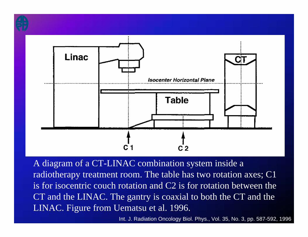
Int. J. Radiation Oncology Biol. Phys., Vol. 35, No. 3, pp. 587-592, 1996
A diagram of a CT-LINAC combination system inside a radiotherapy treatment room. The table has two rotation axes; C1is for isocentric couch rotation and C2 is for rotation between the CT and the LINAC. The gantry is coaxial to both the CT and the LINAC. Figure from Uematsu et al. 1996.

Isocenter Verification

Uematsu M, Shioda A, Tahara K, et al. Daily positioning accuracy of frameless stereotactic radiation therapy with a fusion of computed tomography and linear accelerator (focal) unit: Evaluation of z-axis with a z-marker. Radiotherapy and Oncology 1999;50:337-339.

Uematsu et al, Int J Radiat Oncol Biol Phys 2000; 48 (2):443-448.
Intrafractional tumor position stability during computed tomography (CT)-guided frameless stereotactic radiation therapy for lung or liver cancers with a fusion of CT and linear accelerator (FOCAL) unit.
Uematsu M, Shioda A, Suda A, Tahara K, Kojima T, Hama Y, Kono M, Wong JR, Fukui T, Kusano S
Int J Radiat Oncol Biol Phys 2000; 48 (2):443-448.
Simulator + CT + Linac


Uematsu et al. Computed tomography-guided frameless stereotactic radiotherapy for stage I non-small cell lung cancer: a 5-year experience. IntJ Radiat Oncol Biol Phys 2001;51:666-670.

Figure 5. A conventional AcQSim CT scanner (Philips Medical Systems) was installed in a treatment room at the Memorial Sloan-Kettering Cancer Center, New York. A sliding couch top was used to transport the patient from the CT scanner table to the therapy treatment table. The therapy table was rotated to connect with the CT table. Picture is from Hua et al. 2003.


Figure 2. The Siemens Primatom™ CT-on-rails system, which contains a Primus™ linear accelerator and a Somatom™ sliding-gantry CT scanner (CT-on-Rails). The left picture was the first Primatom unit installed at the Morristown Memorial Hospital, New Jersey. Picture curtsey of Lisa Grimm, Ph.D. The right picture shows a recent model of the unit installed at the Fox Chase Cancer Center, Philadelphia, PA. Picture curtsey of Charlie Ma, Ph.D.

Figure 4. A CT-on-Rails system combining a GE Smart Gantry CT scanner and a Varian 2100EX linear accelerator was installed at the M.D. Anderson Cancer Center. After rotating the couch 180 degrees, a patient can receive a CT scan while in the immobilized treatment position just prior to the start of radiation treatment.
Side rail to provide balance
Magnetic encoder strip
Moving gantry CT scanner
Therapy linear accelerator
Common patient table


Figure 3. In the GE Smart Gantry ™ CT-on-Rails system, two side rails keep the gantry horizontal when scanning. One middle rail keeps the gantry moving straight along the axis of the scanning. Picture is from Kuriyama et al. 2003.


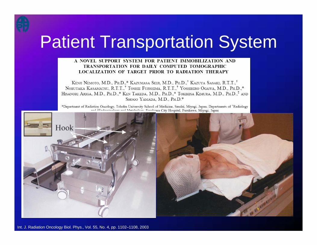
Int. J. Radiation Oncology Biol. Phys., Vol. 55, No. 4, pp. 1102–1108, 2003
Patient Transportation System

Patient Transportation System
Workflow

Int. J. Radiation Oncology Biol. Phys., Vol. 35, No. 3, pp. 587-592, 1996
A diagram of a CT-LINAC combination system inside a radiotherapy treatment room. The table has two rotation axes; C1is for isocentric couch rotation and C2 is for rotation between the CT and the LINAC. The gantry is coaxial to both the CT and the LINAC. Figure from Uematsu et al. 1996.

Example of workflow
1. CT scanning of the target with 2 mm slice spacing
2. Selecting the center of the target, 3. Placing two tiny radio-opaque markers on the
surface of the patient or the immobilization device to mark the isocenter,
4. Re-CT scanning to verify marker positions relative to the target
5. Aligning markers with linac’s treatment beams.
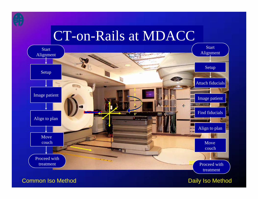
CT-on-Rails at MDACCStart
Alignment
Move couch
Align to plan
Image patient
Setup
Proceed withtreatment
Attach fiducials
Find fiducials
StartAlignment
Move couch
Align to plan
Image patient
Setup
Proceed withtreatment
Common Iso Method Daily Iso Method
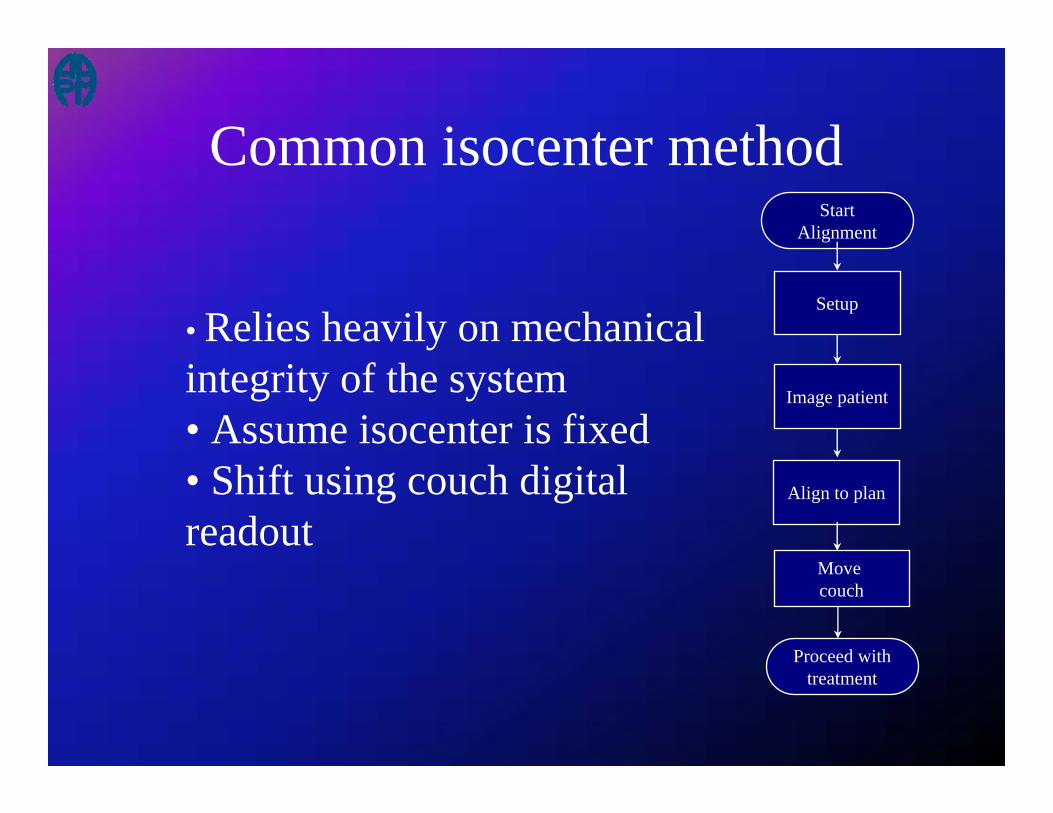
Common isocenter methodStart
Alignment
Move couch
Align to plan
Image patient
Setup
Proceed withtreatment
• Relies heavily on mechanical integrity of the system• Assume isocenter is fixed• Shift using couch digital readout

Daily isocenter methodStart
Alignment
Move couch
Align to plan
Image patient
Setup
Proceed withtreatment
Attach fiducials
Find fiducials
•Reduced reliance on system’s mechanical integrity•Assume isocenter varies daily•Removes uncertainties in couch position•Fiducials to define isocenter•Shift patient using lasers
Mechanical Precision


Uncertainties in Various Steps
• the patient couch position on the linac side after a rotation• the patient couch position on the CT side after a rotation• the precision of the couch position as indicated by its digital
readout• the difference in couch sag between the CT and linac positions• the geometric accuracy of the reconstructed CT images• the identification of fiducial markers from CT images (if
necessary)• the alignment with setup lasers• the alignment of the planning contours with the anatomy in the
CT image (under ideal conditions without organ deformation).

Uncertainty, mmSource of uncertaintyLongitudinal Lateral Vertical
Align scale with laser 0.2 0.2 0.2Couch position at LINAC side negligible negligible negligibleCouch position at CT side negligible 0.5 negligibleCouch digital readout 0.3 0.3 0.3CT coordinates negligible negligible negligibleIdentification of fiducial coordinates 0.2 0.1 0.1Alignment of contours with structures 0.4 0.3 0.3Variation in couch sag differences negligible negligible 0.2
Individual uncertainties (in 1-SD)
• Only two uncertainties larger than 0.3mm
Dong / MD Anderson
Court L, Rosen I, Mohan R and Dong L 2003 Evaluation of mechanical precision and alignment uncertainties for an integrated CT/LINAC system Medical Physics, 30, 1198-210.

Effect of couch sag after a couch rotation
0
1
2
3
4
0 1 2 3 4SAG at CT side, mm
Sag
at L
INA
C si
de, m
m
Couch fully extendedCouch halfway extended
Line of equal sag
C2
Figure 6. Measurements of couch sag for various weight loads after an 180-degree couch rotation in a CT-linac system. Ideally, the amount of sag should be equal after a couch rotation to maintain spatial symmetry between the linac and CT coordinates.

Uncertainty in Couch Rotation
Linac
CTUncertainty: 0.5mm

Precision for the two methods
( )2 2couch CTσ σ+
( )2 2 2 2 2, ,couch coordinates couch CT couch LINAC sagσ σ σ σ σ= + + +
2coordinatesσ
Common isocenter method
2 2 2 2CT plantotal I I shiftσ σ σ σ= + +
2bbσ
2contourσ
2contourσ 2
LσDaily isocenter method
+ +
+ +
2totalσ =
2totalσ =

Uncertainty (mm)Setup protocol Longitudinal Lateral VerticalDaily isocenter 0.5 0.4 0.4Common isocenter 0.6 0.7 0.6
(0.5 without sag)
Predicted uncertainty

Radiation Dose from CT Imaging

Where is the concern?
• CT-guided treatments– Multiple, repeated imaging
• 42 fractions for prostate treatments– Low CT dose becomes a concern

Objectives
• Measure the typical daily CT dose from in-room CT-guided radiotherapy– abdomen/pelvis– head & neck– thoracic
• Compare with current practice using weekly portal films or EPIDs

TLD in Pelvis Phantom
0.6cm4.0cm
10.7cm
1.5cm
8.8cm

TLD in Head & Neck Phantom
0.9cm
1.8cm
3.8cm
7.1cm

TLD in Head & Neck Phantom
1.6cm
2.6cm 4.7cm
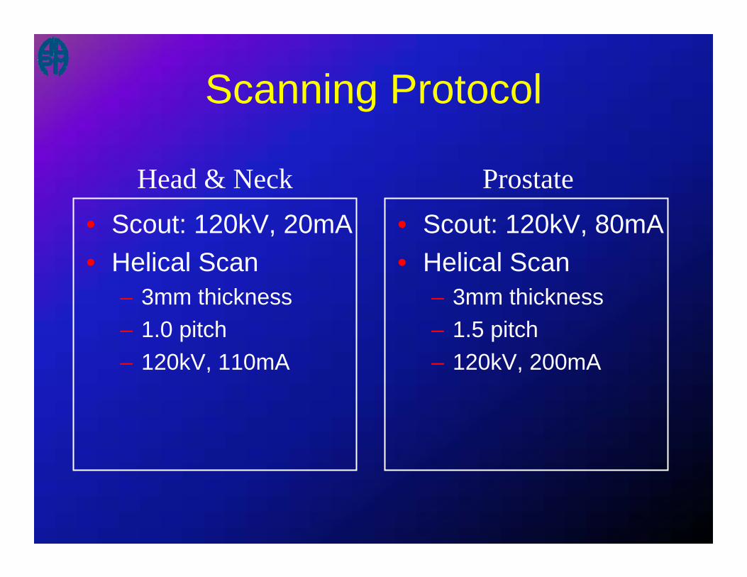
Scanning Protocol
• Scout: 120kV, 20mA• Helical Scan
– 3mm thickness– 1.0 pitch– 120kV, 110mA
• Scout: 120kV, 80mA• Helical Scan
– 3mm thickness– 1.5 pitch– 120kV, 200mA
Head & Neck Prostate

TLD Calibration
• TLD Calibration Water Tank– tube holds TLD at
isocenter– fill with water to place
TLD at desired depth• 6MV photons• depth = dmax (1.5cm)
Dose(cGy) = 0.8259*TLD(uC)
TLD Calibration (6MV)
0
2
4
6
8
10
12
14
16
0 5 10 15 20
Average TLD Reading (uC)
Dos
e (c
Gy)
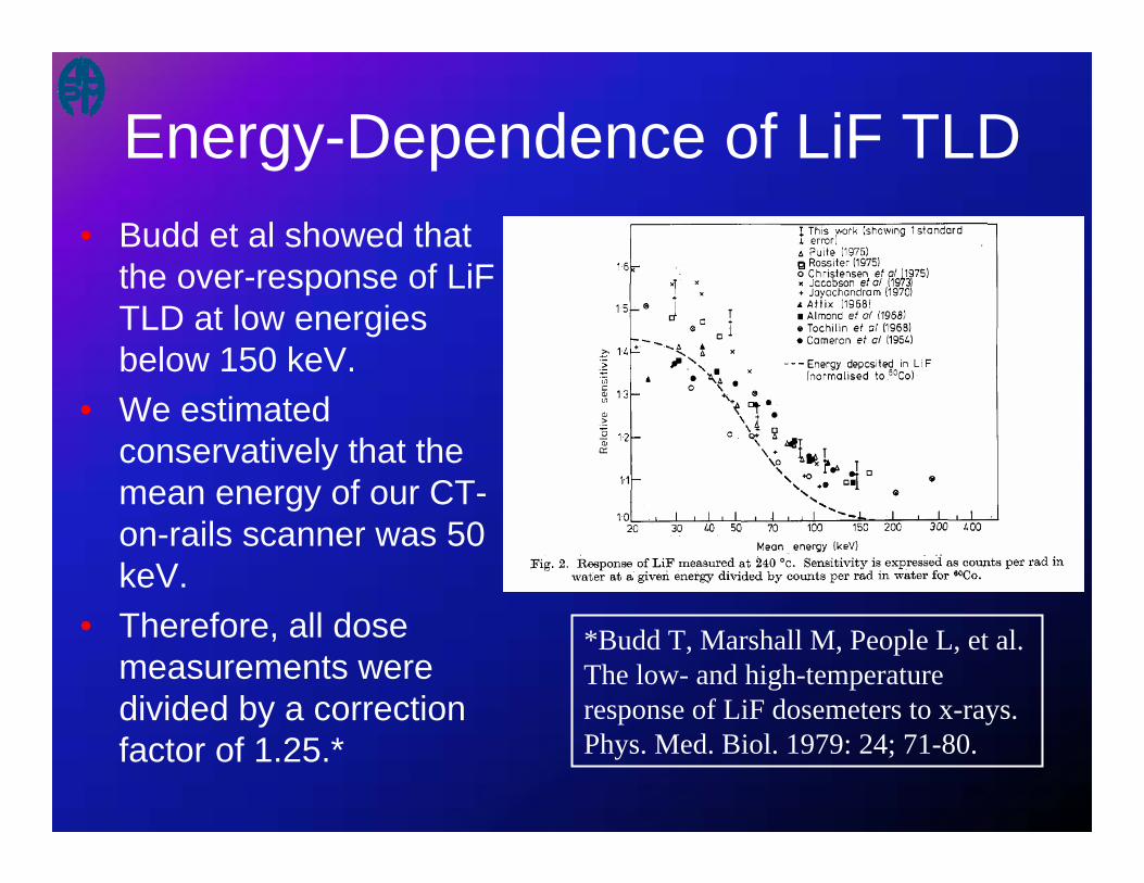
*Budd T, Marshall M, People L, et al. The low- and high-temperature response of LiF dosemeters to x-rays. Phys. Med. Biol. 1979: 24; 71-80.
Energy-Dependence of LiF TLD• Budd et al showed that
the over-response of LiFTLD at low energies below 150 keV.
• We estimated conservatively that the mean energy of our CT-on-rails scanner was 50 keV.
• Therefore, all dose measurements were divided by a correction factor of 1.25.*
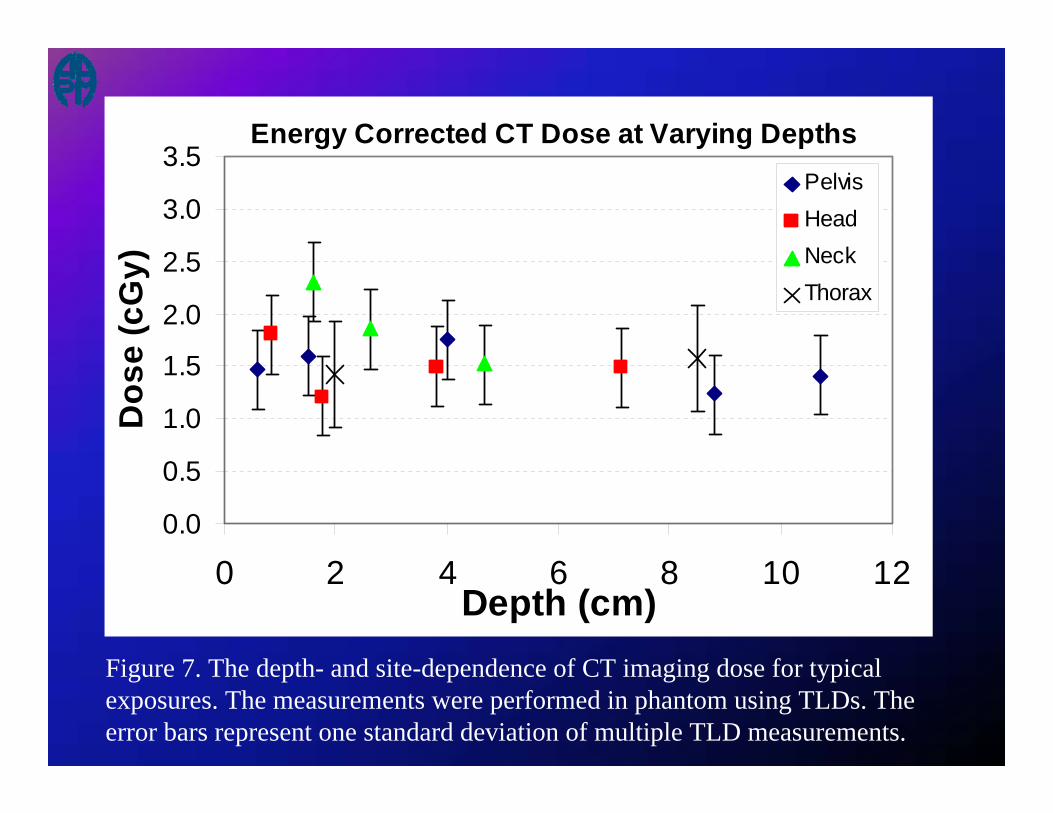
Energy Corrected CT Dose at Varying Depths
0.0
0.5
1.0
1.5
2.0
2.5
3.0
3.5
0 2 4 6 8 10 12Depth (cm)
Dos
e (c
Gy)
PelvisHeadNeckThorax
Figure 7. The depth- and site-dependence of CT imaging dose for typical exposures. The measurements were performed in phantom using TLDs. The error bars represent one standard deviation of multiple TLD measurements.

Dose from Portal Films• One film = 6 - 8 MU• Two orthogonal films each week, 8 weeks of
treatment, assuming no repeat films.– 96 - 128 MU ~ 100 cGy
• Typical prescription for prostate = 7560 cGy• Typical prescription for head&neck = 7000
cGy~ 1.3% of prescription dose for prostate~ 1.4% for prescription dose for head&neck
CT dose~2 cGy x 42 = ~84 cGy

Quality Assurance
For in-room CT imaging

QA for CT Scanner
• AAPM Task Group #2 “Specification and acceptance testing of computed tomography scanners” (Lin et al. 1993)
• Task Group #66 “Quality assurance for computed-tomography simulators and the computed-tomography-simulation process”.(Mutic et al. 2003)– In-room CT is very similar to the function of a CT
simulator.

Spatial integrity
• The mechanical precision of the CT scanner should be able to determine a patient’s position on a shared treatment couch to within 1 mm relative to the treatment beam.
• Any vibration or miscalibration of the CT gantry moving on rails could result in either poor image quality or spatially displaced objects. It is recommended that a long, straight, and leveled object should be scanned along the gantry movement direction to determine any jittering or spatial non-linearity issues.
Low Contrast resolution
• The contrast resolution is defined as the CT scanner’s ability to distinguish relatively large objects which differ only slightly in density from background.
• For the moving-gantry CT scanner, the low contrast resolution is worse than conventional couch-moving CT scanners. – 1.5% contrast level at 3 mm object – 0.3% for conventional (couch-moving) CT

Positioning laser systems
• Two laser positioning systems are usually installed: – Linac laser system for patient setup– CT laser for position verifications
• Lasers are temporary in-room reference

Safety Interlocks
• X-ray On interlock• Interlock for couch center position• Interlock for couch height• Collision interlocks• Park position

Comparison with weekly portal filming
• Portal Films (2 orthogonal films, once/week)~100 cGy (1.3 – 1.4 % of prescription dose)* This is conservative because the portal dose from
repeat films were not included.• Daily CT, assuming ~2 cGy per scan, 42 fractions
~84 cGy (1.1 – 1.2 % of prescription dose)
Therefore, if daily CT replaces portal films, the imaging dose for patient alignment is comparable.

CT scanning protocols
• Site-dependent and application dependent– mA– Slice spacing– Slice thickness– Pitch– Scan field-of-view– Scan length

ConnectivityVARiS Treat - MLC
Workstation
EXCIInterface
Advantage SimGE CTConsole
TreatClinic
VisionMatch
Varian 21 EX w/120 MLC & PortalVision Tx Control Area & GE CT Simulator
Dyn MLC
In-RoomMonitor
MLCController
Clinac EX w/ MLC & PVPortalVisionImage Acq
Syst
AVI 6.0
Dyn MLC
MLCController
MatchVision
ClinicTreat
Clinac EX w/ MLC & PV
VARiS Treat - MLC -PortalVision WkstnPortalVision
Image AcqSyst
Treatment Planning & Image Review
EXCIInterface
ClinacConsole
AVI 6.0In-RoomMonitor
CadPlan Helios
SomaVisionWorkstation
Dicom 3
OverlayVision
Clinic
Match
VisionOverlayMatch
Clinic
Computer Servers
VARiS/VisionMediumServer
Medium ImageServer
Clinic VisionOverlayMatch
Dicom RT
Dicom RT
Link
VARiS / VisionWorkstation
VisionOverlayMatch
Clinic

General Recommendations
• Daily tests– CT number reproducibility and uniformity test– High contrast resolution (visual inspection)
• Monthly tests– Repeat daily tests– Alignment test using a phantom
• Annual tests– CT scanner annual calibration/tests
• CT number accuracy• Spatial integrity• Image quality• Imaging dose• Interlock systems• Application specific tests

In-room CT-guided Applications

CT-guided RT
• Reposition patient based on pre-treatment CT images– Rigid-body movement (translation)– Rotation: rare
• Replan– Mid-course correction– Image-guided adaptive radiotherapy
• Single treatment– SRS/SRT– Palliative treatments

Prostate• 1. Hua CH, Lovelock DM, Mageras GS, et al. Development of a semi-
automatic alignment tool for accelerated localization of the prostate. Int J Radiat Oncol Biol Phys 2003;55:811-824.
• 2. Court LE, Dong L. Automatic registration of the prostate for computed-tomography-guided radiotherapy. Med Phys 2003;30:2750-2757.
• 3. Paskalev K, Ma CM, Jacob R, et al. Daily target localization for prostate patients based on 3D image correlation. Phys Med Biol 2004;49:931-939.
• 4. Fung AYC, Enke CA, Ayyangar KM, et al. Prostate motion and isocenter adjustment from ultrasound-based localization during delivery of radiation therapy. International Journal of Radiation Oncology Biology Physics 2005;61:984-992.
• 5. Wong JR, Grimm L, Oren R, et al. Image-guided radiotherapy for prostate cancer by CT-linear accelerator combination: Prostate movements and dosimetric considerations. International Journal of Radiation Oncology Biology Physics 2005;61:561-569.

Example of setup error and organ variation during the course of prostate radiotherapy
• Contours from treatment planning CT are overlaid as reference
• Patient aligned with BBs

Comparison of Bony and Direct Target Localization
Bony Registration Direct Target Localization“freezing” the prostate!
Para-spinal Lesion
• 1. Yenice KM, Lovelock DM, Hunt MA, et al. CT image-guided intensity-modulated therapy for paraspinal tumors using stereotactic immobilization. Int J Radiat Oncol Biol Phys 2003;55:583-593.
• 2. Shiu AS, Ye J-S, Lii M, et al. Near simultaneous computed tomography image-guided stereotactic spinal radiotherapy: An emerging paradigm for achieving true stereotaxy. International Journal of Radiation Oncology Biology Physics 2003;57:605-613.

Lung Cancers
• 1. Uematsu M, Fukui T, Shioda A, et al. A dual computed tomography linear accelerator unit for stereotactic radiation therapy: a new approach without cranially fixated stereotactic frames. Int J Radiat Oncol Biol Phys 1996;35:587-592.
• 2. Uematsu M, Shioda A, Tahara K, et al. Focal, high dose, and fractionated modified stereotactic radiation therapy for lung carcinoma patients: A preliminary experience. Cancer1998;82:1062-1070.
• 3. Uematsu M. CT-guided stereotactic radiotherapy for early stage lung cancer. Nippon rinsho Japanese journal of clinical medicine 2002;60 Suppl 5:408-410.
• 4. Uematsu M. Stereotactic radiation therapy for non small cell lung cancer. Nippon Geka Gakkai zasshi 2002;103:256-257.
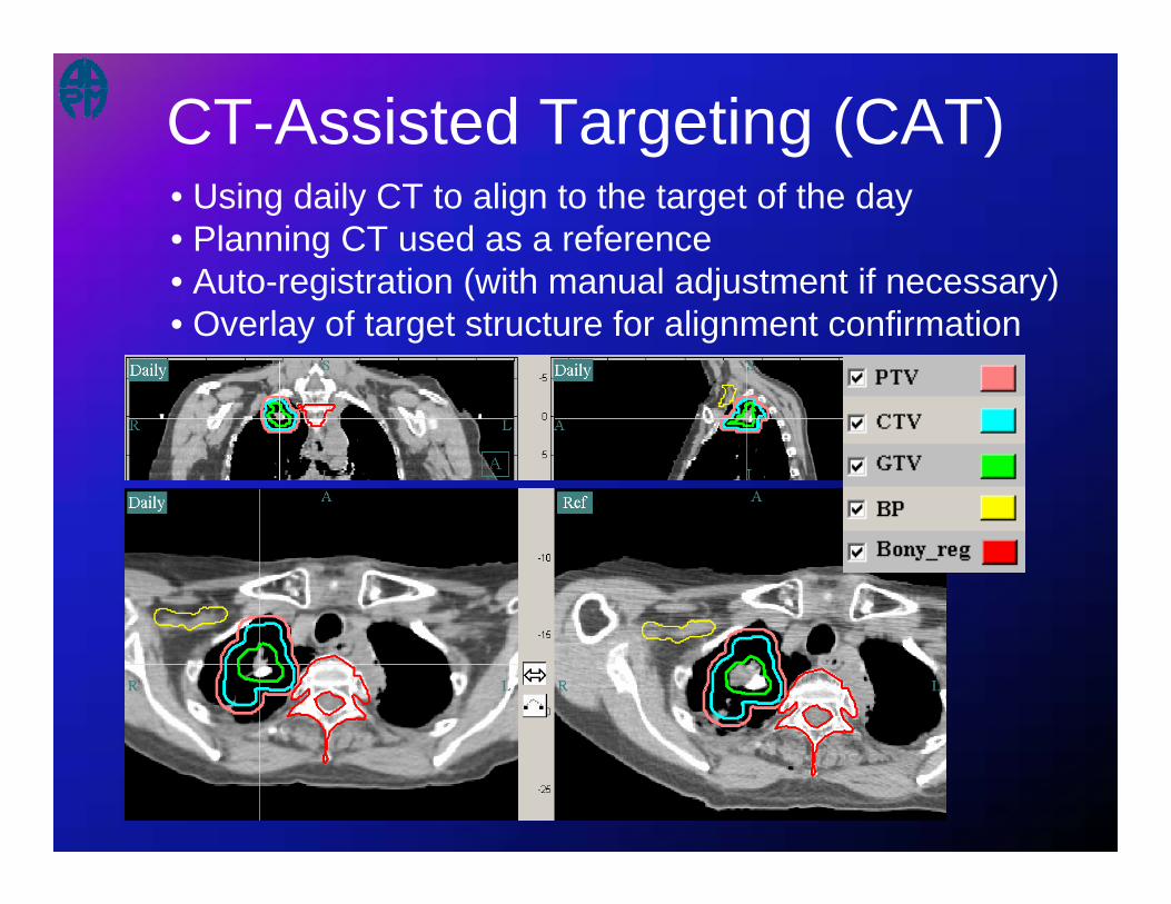
CT-Assisted Targeting (CAT)• Using daily CT to align to the target of the day• Planning CT used as a reference• Auto-registration (with manual adjustment if necessary)• Overlay of target structure for alignment confirmation

#1 #2
#3 #4
Plan Dry-run

---- 40 Gy---- 30 Gy---- 20 Gy---- 10 Gy
Dose Overlay (animation)Prescription: 10 Gy x 3 fxs with IMRT10 Gy x 1 boost AP/PA

CT-guided Adaptive Radiotherapy

Treatment Room
Treatment Planning
CT scanner CT-Simulation Treatmentplanning system
LINAC console
LINAC Patient couch CT-on-Rails
CT console AlignmentWorkstation
Console
On/OffOn/Off--linelineAdaptiveAdaptive
RadiotherapyRadiotherapy
A workflow diagram for in-room CT-guided adaptive radiotherapy
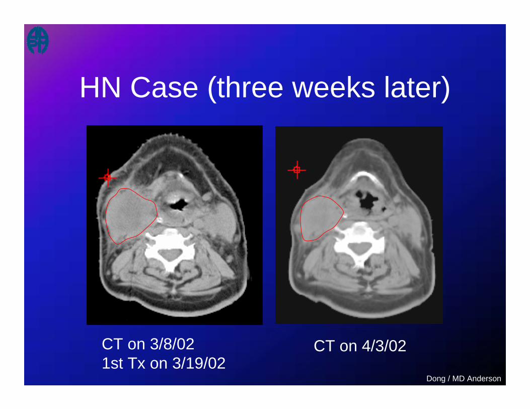
HN Case (three weeks later)
CT on 3/8/021st Tx on 3/19/02
CT on 4/3/02
Dong / MD Anderson
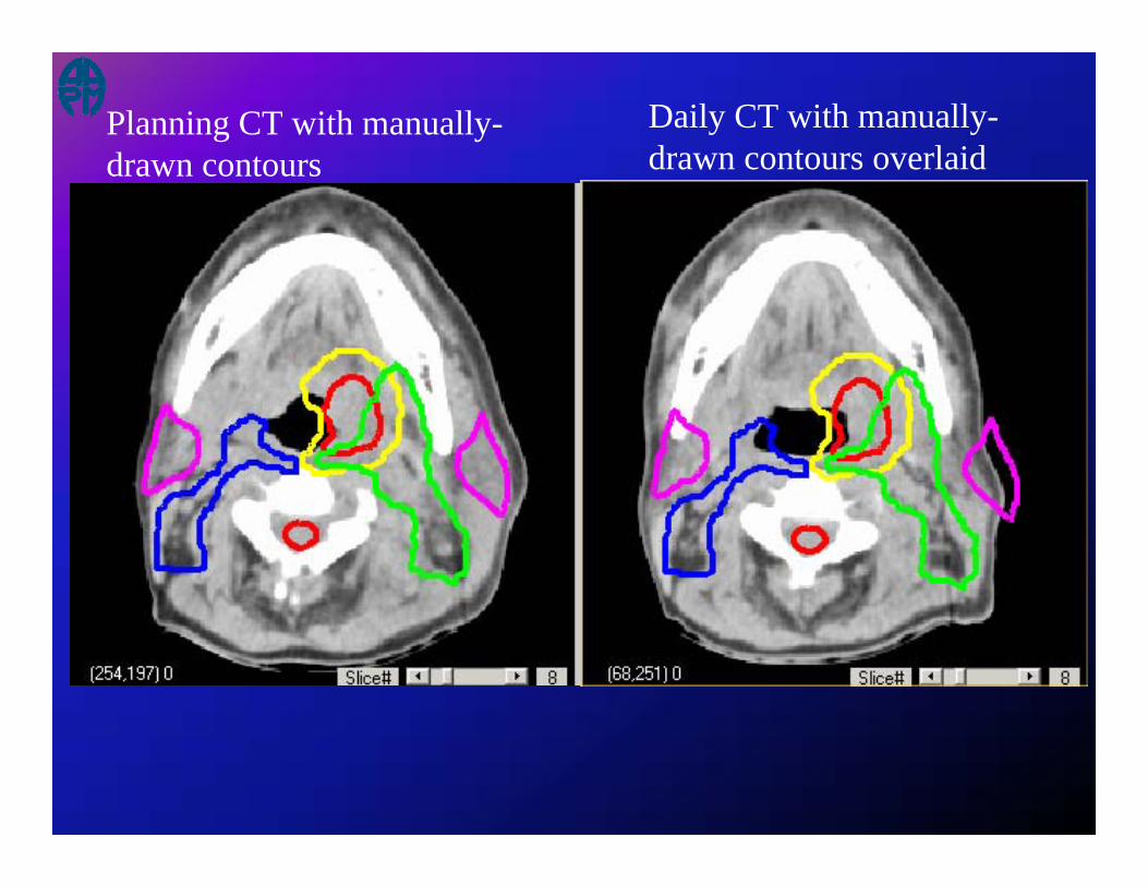
Planning CT with manually-drawn contours
Daily CT with manually-drawn contours overlaid

Planning CT with manually-drawn contours
Daily CT with auto-delineatedoriginal contours

Planning CT with manually-drawn contours
Daily CT with auto-delineatedoriginal contours

Daily CTPlanning CT
Target Before Treatment

19 Treatment CT scans acquired during the course of head & neck radiotherapy
Setup Uncertainties In Head & Neck Treatment
Elapsed Treatment Days
Movie Clip: Head & Neck Case
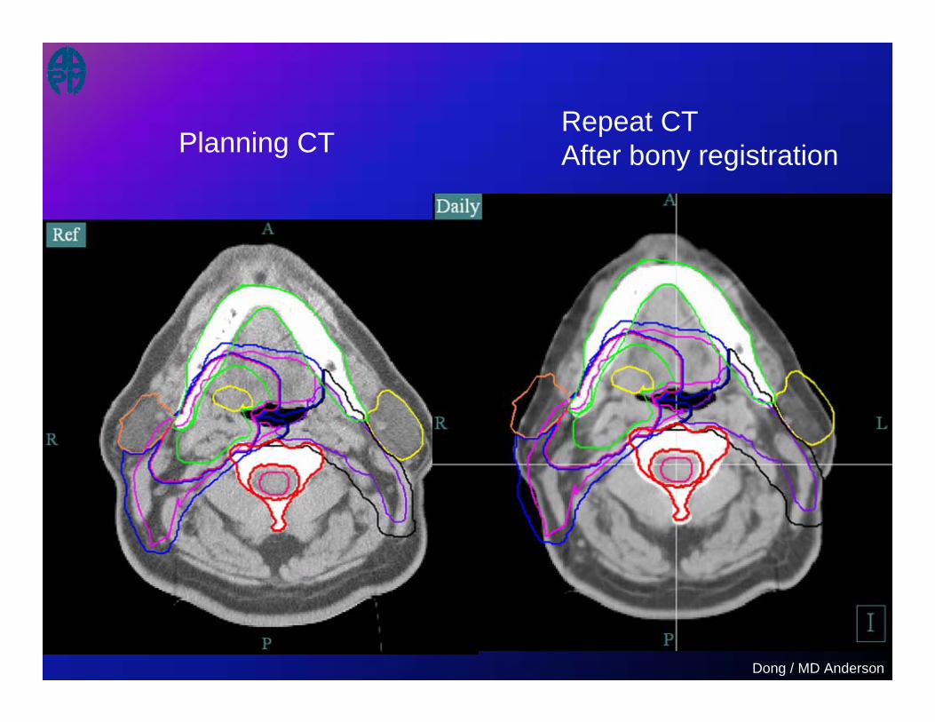
Planning CTRepeat CTAfter bony registration
Dong / MD Anderson

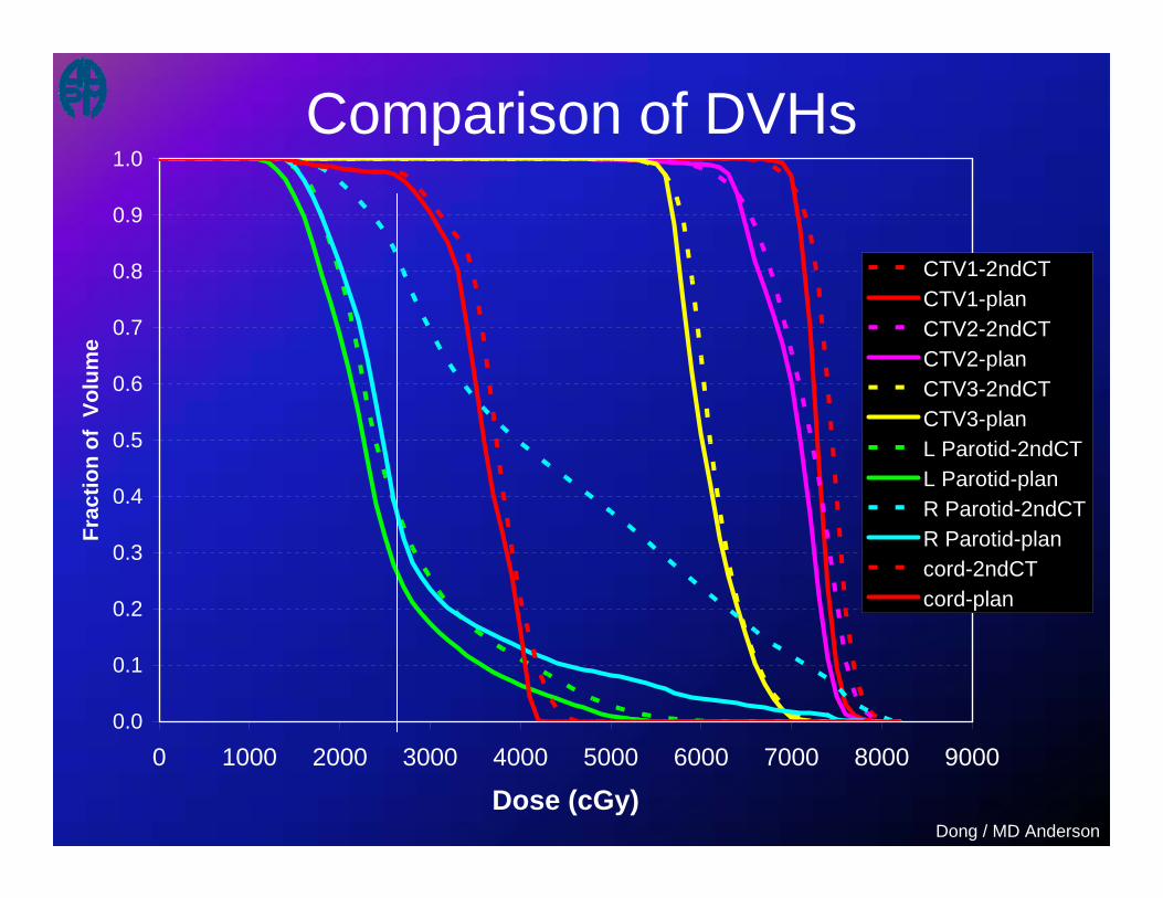
Dosimetric Impact of Anatomy Variation
Dong / MD Anderson

Dosimetric Impact of Anatomy Variation
Dong / MD Anderson

Dosimetric Impact of Anatomy Variation
Dong / MD Anderson
0.0
0.1
0.2
0.3
0.4
0.5
0.6
0.7
0.8
0.9
1.0
0 1000 2000 3000 4000 5000 6000 7000 8000 9000
Dose (cGy)
Frac
tion
of V
olum
e
CTV1-2ndCTCTV1-planCTV2-2ndCTCTV2-planCTV3-2ndCTCTV3-planL Parotid-2ndCTL Parotid-planR Parotid-2ndCTR Parotid-plancord-2ndCTcord-plan
Comparison of DVHs
Dong / MD Anderson

Summary and Discussion• In-room CT imaging extends “CT simulation”
just prior to each treatment• Mature technology for in-room IGRT• 3D definition of anatomy
– Familiar by physicians• Dose calculation
– Replanning– Online “Plan & Treat”
• Image Guidance– Setup correction– Treatment monitoring
• Learning