Embed Size (px)
Citation preview
5G NR Base Station PerformanceTestsin remote control according to TS 38.141-1 Rel. 15Application Note (preliminary)
Products:
● R&S®SMW200A
3GPP TS38.141-1 defines conducted conformance tests for 5G NR base stations according to Release15. This application note describes how all required peformance (Px) tests (TS38.141-1 Chapter 8) can beperformed quickly and easily by using remote control of vector signal generators from Rohde & Schwarz.A software program enables and demonstrates remote operation.
Note:
Visit our homepage for the most recent version of this application note (www.rohde-schwarz.com/appnote/GFM315).
Appli
catio
n Note
(pre
limina
ry)
GFM3
15_0
e
Contents5G NR Base Station Performance Tests
2Application Note (preliminary) 5G NR Base Station Px (DRAFT) ─ GFM315_0e
Contents1 Introduction............................................................................................ 3
2 General Performance Tests...................................................................5
3 Performance Tests (Chapter 8)............................................................. 9
4 Appendix...............................................................................................40
5 Rohde & Schwarz.................................................................................44

Introduction5G NR Base Station Performance Tests
3Application Note (preliminary) 5G NR Base Station Px (DRAFT) ─ GFM315_0e
1 Introduction5G New Radio (NR) aims on three main services:
● High data rate services (Enhanced Mobile Broad Band = eMBB)● Massive internet of things (Massive Machine Type Communication = mMTC)● Ultra reliable low latency services (URLLC)
Release 15 (also called phase 1) focuses on eMBB and URLLC.
An overview of the technology behind 5G NR is provided in the Rohde & Schwarz book[4]
The 5G NR conformance tests for base stations are defined in 3GPP TS 38.141Release 15 [1] and include transmitter (Tx), receiver (Rx) and performance (Px) tests.3GPP defines two parts:
● TS 38.141-1: Part 1: Conducted conformance testing● TS 38.141-2: Part 2: Radiated conformance testing
T&M instruments from Rohde & Schwarz can be used to perform all tests easily andconveniently.
This application note describes the performance (Px) tests in line with TS38.141-1Chapter 8. It explains the tests and the remote control of vector signal generators. Afree remote-operation software program is additionally provided. With this software,users can remotely control and demo tests on base stations quickly and easily. It alsoprovides the SCPI commands required to implement each test in user-defined test pro-grams.
The transmitter (Tx) tests (TS38.141-1 Chapter 6) are described in Application NoteGFM313.
The receiver (Rx) tests (TS38.141-1 Chapter 7) are described in Application NoteGFM314.
Table 1-1 gives an overview of the receiver tests defined in line with Chapter 8ofTS38.141-1. All can be carried out using instruments from Rohde & Schwarz. Thesetests are individually described in this application note.

Introduction5G NR Base Station Performance Tests
4Application Note (preliminary) 5G NR Base Station Px (DRAFT) ─ GFM315_0e
Table 1-1: Conducted Performance Characteristics (Chapter 8) Release 15
Chapter(TS38.141-1)
Test Comment
8.2 PUSCH
8.2.1 PUSCH with precoding disabled
8.2.2 PUSCH with precoding enabled
8.3. PUCCH
8.3.1 PUCCH format 0
8.3.2 PUCCH format 1
8.3.2.1 NACK to ACK
8.3.2.2 ACK missed
8.3.3. PUCCH format 2
8.3.3.1 ACK missed
8.3.3.2 UCI BLER
8.3.4 PUCCH format 3
8.3.5 PUCCH format 4
8.4 PRACH
8.4.1 PRACH false alarm and missed detection
The following abbreviations are used in this Application Note for Rohde & Schwarz testequipment:
● The R&S®SMW200A vector signal generator is referred to as the SMW.

General Performance Tests5G NR Base Station Performance Tests
5Application Note (preliminary) 5G NR Base Station Px (DRAFT) ─ GFM315_0e
2 General Performance Tests
2.1 Note
Very high power occurs on base stations! Be sure to use suitable attenuators in orderto prevent damage to the test equipment.
2.2 Base Station Classes and Configurations
2.2.1 Classes
The specification distinguishes three different base station classes [1, chapter 4.4].
In the different tests they require different power levels.
Table 2-1: BS classes
Name Cell size minimum coupling loss
Wide Area Macro cell 70 dB
Medium range Micro cell 53 dB
Local Area Pico cell 45 dB
2.2.2 Configuration
This application note covers conducted measurements. For easy reading and in thetest setups in this application note, only one version is mentioned.
In [1] two different base station types defined for Frequency Range 1 (FR1):
1-C (FR1 conducted)
This is the well known conducted base station where the Transmit/Receive ports areavailable directly.
1-H (FR1 hybrid)
This type has two reference point. First the Transceiver array boundary (TAB) which isequipped with connectors for conducted measurements. Second the radiated interfaceboundary (RIB). All measurements in this application note apply for the TAB. For mea-
Base Station Classes and Configurations

General Performance Tests5G NR Base Station Performance Tests
6Application Note (preliminary) 5G NR Base Station Px (DRAFT) ─ GFM315_0e
surements at the RIB over-the-air (OTA) tests are necessary. They are part ofTS38.142-2.
Figure 2-1: Radiated and conducted reference points for BS type 1-H [1]
2.3 Performance Test Setup
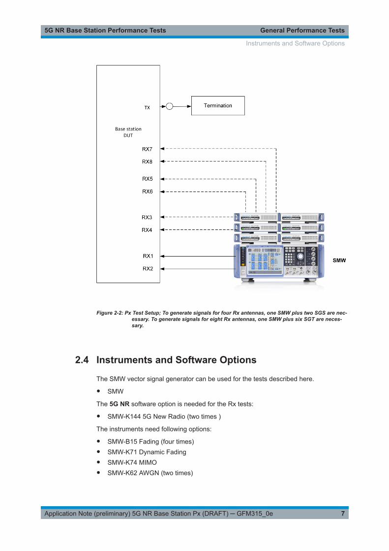
shows the general test setup for performance tests. An SMW is used to perform thetest. Some tests are for four or eight Rx antennas. One SMW with additional RF sour-ces like the SGS can generate the necessary signals for four Rx antennas. To gener-ate signals for eight Rx antennas, one SMW with additional six RF sources like SGSand SGT are needed. Some tests require special MIMO combining setups; these aredescribed in the respective sections.
Performance Test Setup
General Performance Tests5G NR Base Station Performance Tests
7Application Note (preliminary) 5G NR Base Station Px (DRAFT) ─ GFM315_0e
Figure 2-2: Px Test Setup; To generate signals for four Rx antennas, one SMW plus two SGS are nec-essary. To generate signals for eight Rx antennas, one SMW plus six SGT are neces-sary.
2.4 Instruments and Software Options
The SMW vector signal generator can be used for the tests described here.
● SMW
The 5G NR software option is needed for the Rx tests:
● SMW-K144 5G New Radio (two times )
The instruments need following options:
● SMW-B15 Fading (four times)● SMW-K71 Dynamic Fading● SMW-K74 MIMO● SMW-K62 AWGN (two times)
Instruments and Software Options
General Performance Tests5G NR Base Station Performance Tests
8Application Note (preliminary) 5G NR Base Station Px (DRAFT) ─ GFM315_0e
● SMW-K145 5G NR Closed Loop BS Tests (two times)
A couple of tests require four Rx antennas. This can be handled with one SMW plustwo external RF generators.
● 1 x SMW + 2 x SGT● SMW-K19 Dig IQ
To generate signals for eight Rx antennas, one SMW with six external RF generators isused:
● 1 x SMW + 6 x SGT● SMW-K19 Dig IQ
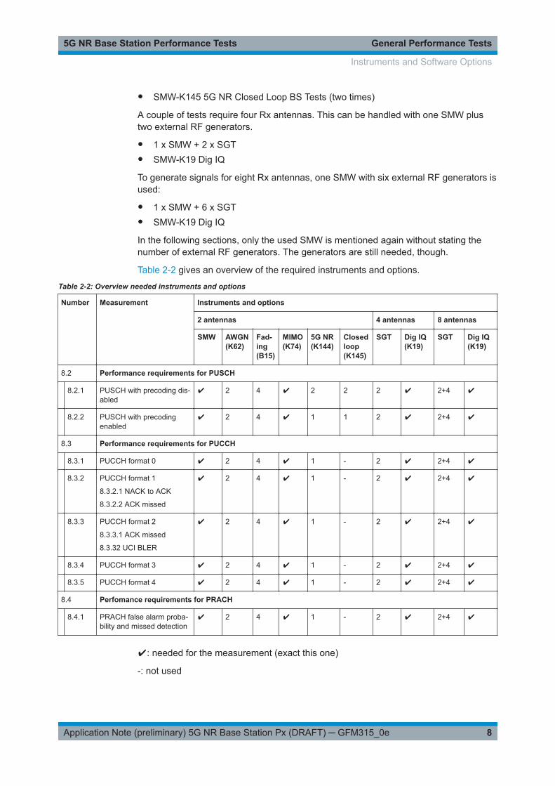
In the following sections, only the used SMW is mentioned again without stating thenumber of external RF generators. The generators are still needed, though.
Table 2-2 gives an overview of the required instruments and options.
Table 2-2: Overview needed instruments and options
Number Measurement Instruments and options
2 antennas 4 antennas 8 antennas
SMW AWGN(K62)
Fad-ing(B15)
MIMO(K74)
5G NR(K144)
Closedloop(K145)
SGT Dig IQ(K19)
SGT Dig IQ(K19)
8.2 Performance requirements for PUSCH
8.2.1 PUSCH with precoding dis-abled
✔ 2 4 ✔ 2 2 2 ✔ 2+4 ✔
8.2.2 PUSCH with precodingenabled
✔ 2 4 ✔ 1 1 2 ✔ 2+4 ✔
8.3 Performance requirements for PUCCH
8.3.1 PUCCH format 0 ✔ 2 4 ✔ 1 - 2 ✔ 2+4 ✔
8.3.2 PUCCH format 1
8.3.2.1 NACK to ACK
8.3.2.2 ACK missed
✔ 2 4 ✔ 1 - 2 ✔ 2+4 ✔
8.3.3 PUCCH format 2
8.3.3.1 ACK missed
8.3.32 UCI BLER
✔ 2 4 ✔ 1 - 2 ✔ 2+4 ✔
8.3.4 PUCCH format 3 ✔ 2 4 ✔ 1 - 2 ✔ 2+4 ✔
8.3.5 PUCCH format 4 ✔ 2 4 ✔ 1 - 2 ✔ 2+4 ✔
8.4 Perfomance requirements for PRACH
8.4.1 PRACH false alarm proba-bility and missed detection
✔ 2 4 ✔ 1 - 2 ✔ 2+4 ✔
✔: needed for the measurement (exact this one)
-: not used
Instruments and Software Options

Performance Tests (Chapter 8)5G NR Base Station Performance Tests
9Application Note (preliminary) 5G NR Base Station Px (DRAFT) ─ GFM315_0e
3 Performance Tests (Chapter 8)Performance tests are for the receiver of the base station. The base station typicallymeasures the throughput (for PUSCH tests) or the ability to detect certain signal(PUCCH and PRACH) under multipath channel conditions.
Fixed Reference Channels (FRC)
For the performance tests, Fixed Reference Channels (FRC) are defined. They contain5G NR channel parameters as modulation, code rate and allocated resource blocksetc. They are named according to [1], annex A and split in different subsets:
● G-FR1-A3: A3-1…A3-32 (QPSK), with or without transform precoding, UL-DMRS-add position 0 or 1, 1 or 2 layers
● G-FR1-A4: A4-1…A4-28 (16QAM), without transform precoding, UL-DMRS-addposition 0 or 1, 1 or 2 layers
● G-FR1-A5: A5-1…A5-14 (64QAM), without transform precoding, UL-DMRS-addposition 0 or 1, 1 layer
For more details refer to [1], annex A, All FRCs are implemented as predefined set-tings for FDD and TDD in the signal generator family SMW.
Channels
According to [1] the channels to be tested are in the middle (M) and with single carrierof the supported frequency range of the base station.
3.1 Basic Operation Demo Program QuickStep
The block NR_BS_Performance Tests for Quickstep provides all tests accordingTS38.141-1. For basic operation, see Chapter 4.1, "R&S QuickStep", on page 40and the manual [5].
You can create your own test procedure by using the different test blocks.
The block Basics provides principal 5G NR settings independently of the further teststeps. The blocks for individual tests according to the specification provide additionaltest-specific settings.
Basic Operation Demo Program QuickStep

Performance Tests (Chapter 8)5G NR Base Station Performance Tests
10Application Note (preliminary) 5G NR Base Station Px (DRAFT) ─ GFM315_0e
Figure 3-1: Quickstep overview for 5G NR PerformanceTests
Block Basics
Please note that the basic settings are valid for all following tests steps. If you like toperform tests with different settings, you have to create another block Basics.
Basic Operation Demo Program QuickStep

Performance Tests (Chapter 8)5G NR Base Station Performance Tests
11Application Note (preliminary) 5G NR Base Station Px (DRAFT) ─ GFM315_0e
Figure 3-2: The block Basics allows general test-independent settings
● General settings– Reset: Sends a reset command to all connected instruments– External reference: Switches the SMW over to an external reference source
(typ. 10 MHz).● Wanted NR signal
– Frequency in MHz– Deployment– Channel Bandwidth in MHz– SCS 15 kHz, 30 kHz or 60 kHz– Power level in dBm– Cell ID– UE ID– Rx Antennas 2 ,4 or 8 antennas
● Additional Settings– SMW Attenuation in dB– Trigger Mode Armed Auto or Auto
The report looks like this:
Basic Operation Demo Program QuickStep

Performance Tests (Chapter 8)5G NR Base Station Performance Tests
12Application Note (preliminary) 5G NR Base Station Px (DRAFT) ─ GFM315_0e
Figure 3-3: Report: Basics
3.2 Performance Requirement for PUSCH
The physical uplink shared channel (PUSCH) carries user data, it is dynamicallyshared among different users in a cell. Special issues for single PUSCH tests aredescribed in the related subchapters.
All tests in this subclause are performed for a given SNR where the AWGN power levelis given in Table 3-1
Table 3-1: AWGN power level for PUSCH tests
AWGN power level [dBm]
Channel bandwidth
[MHz]
SCS
15 kHz
SCS
30 kHz
SCS
60 kHz
5 - 83.5 (4.50 MHz) - 84.1 (3.96 MHz)* n.a.
10 - 80.3 (9.36 MHz) - 80.7 (8.64 MHz) - 81.1 (7.92 MHz)*
15 - 78.5 (14.22 MHz)* - 78.7 (13.68 MHz)* - 78.94 (12.96 MHz)*
20 - 77.2 (19.08 MHz) - 77.4 (18.36 MHz) - 77.7 (17.28 MHz)*
25 - 76.24 (23.94 MHz)* - 76.4 (23.40 MHz)* - 76.58 (22.32 MHz)*
30 - 75.44 (28.80 MHz)* - 75.6 (28.08 MHz)* - 75.7 (27.36 MHz)*
40 - 74.13 (38.88 MHz)* - 74.25 (38.16 MHz) - 74.4 (36.72 MHz)*
50 - 73.17 (48.60 MHz)* - 73.26 (47.88 MHz)* - 73.36 (46.80 MHz)*
60 n.a. - 72.4 (58.32 MHz)* - 72.52 (56.88 MHz)*
70 n.a. - 71.74 (68.04 MHz)* - 71.8 (66.96 MHz)*
80 n.a. - 71.14 (78.12 MHz)* - 71.2 (77.04 MHz)*
90 n.a. - 70.61 (88.20 MHz)* - 70.66 (87.12 MHz)*
Performance Requirement for PUSCH

Performance Tests (Chapter 8)5G NR Base Station Performance Tests
13Application Note (preliminary) 5G NR Base Station Px (DRAFT) ─ GFM315_0e
AWGN power level [dBm]
100 n.a. - 70.1 (98.28 MHz) - 70.19 (97.20 MHz)*
* Not mentioned in TS38.141-1, calculated values
The test for PUSCH verifies the achieved throughput of a receiver under multipath fad-ing conditions at a given SNR. The throughput is measured by the base station undertest. The required throughput is expressed as a fraction of maximum throughput for theFRCs. HARQ re-transmission is assumed.
Hybrid Automatic Repeat Request (HARQ)-Feedback
The PUSCH tests require a feedback signal from the base station under test to providefeedback for HARQ. The signal generator automatically adjusts the transmitted signalbased on the feedback. Software option SMW-K145 Closed Loop BS Tests is neededto perform tests with base station feedback. Use following input connectors.
Table 3-2: Signals and connectors for PUSCH tests
Signal HARQ feedback (from BS) Frame Trigger (DL timing fromBS)
Connector @ SMW with B10/B-14 TM3 + TM6 (rear panel) USER 3 (front panel)
Connector @ SMW with B9/B-15 TM2 + TM4 (rear panel) USER 3 (front panel)
Note: two connectors for tests with 2 Tx antennas (use T-connector)
SNR Correction Factor
If the used FRC does not occupy the whole PUSCH bandwidth, a special SNR correc-tion factor is applied which depends on the bandwidth, the SCS and the number ofused RBs.
Equation 3-1: SNR Correction factor
Test setup
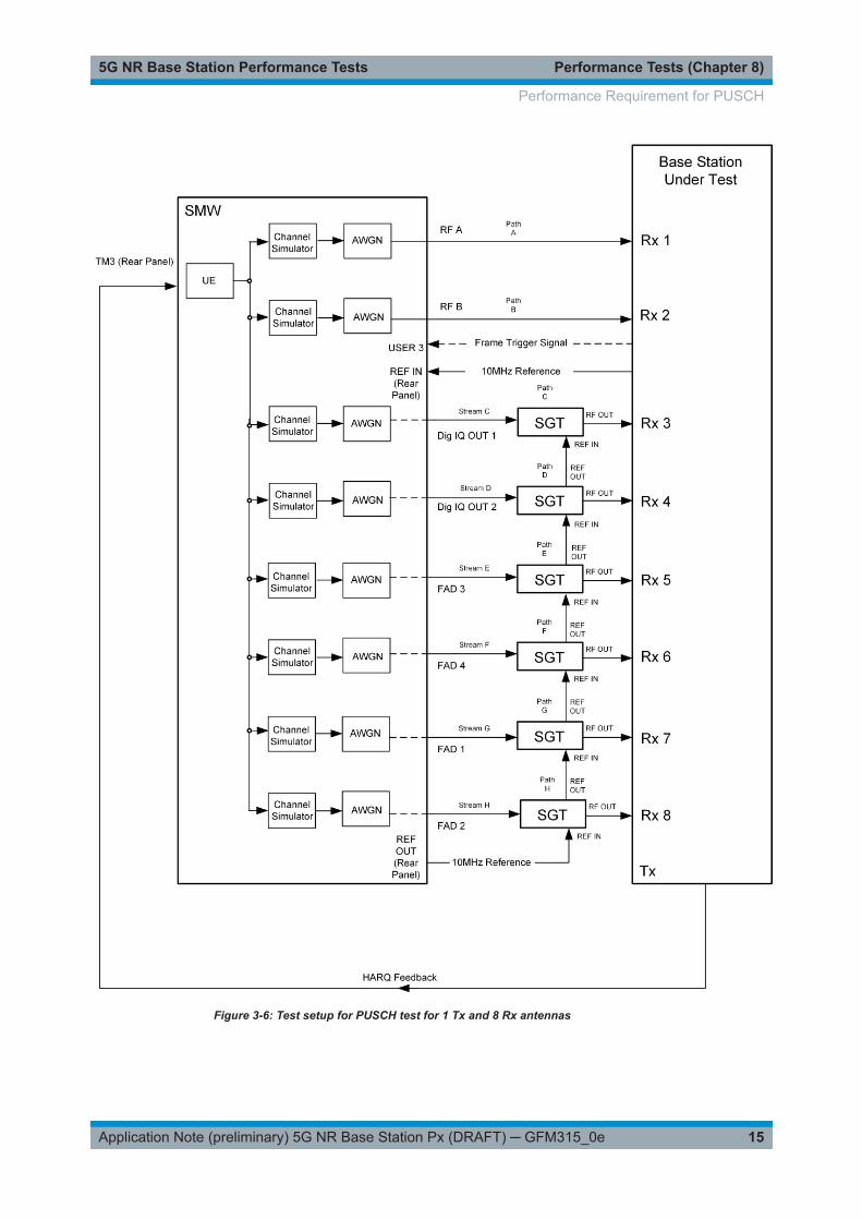
Figure 3-4 to Figure 3-9 show the test setup.
The wanted signal generated by SMW baseband A is split up in two paths. Multipathfading is simulated in the channel simulators. AWGN is added.
For four RX antennas, the test can be done with just one SMW (suitable optionsrequired). For eight RX antennas, the test can be also done with just one SMW.
The SMW needs an external trigger at USER3. A HARQ-Feedback signal from thebase station is required. For SMW with B10/B14 use TM3 (+ TM6), for SMW withB9/B15 use TM2 (+ TM4).
Performance Requirement for PUSCH

Performance Tests (Chapter 8)5G NR Base Station Performance Tests
14Application Note (preliminary) 5G NR Base Station Px (DRAFT) ─ GFM315_0e
Figure 3-4: Test setup for PUSCH test for 1 Tx and 2 Rx antennas
Figure 3-5: Test setup for PUSCH test for 1 Tx and 4 Rx antennas
Performance Requirement for PUSCH
Performance Tests (Chapter 8)5G NR Base Station Performance Tests
15Application Note (preliminary) 5G NR Base Station Px (DRAFT) ─ GFM315_0e
Figure 3-6: Test setup for PUSCH test for 1 Tx and 8 Rx antennas
Performance Requirement for PUSCH

Performance Tests (Chapter 8)5G NR Base Station Performance Tests
16Application Note (preliminary) 5G NR Base Station Px (DRAFT) ─ GFM315_0e
Figure 3-7: Test setup for PUSCH test for 2 Tx and 2 Rx antennas
Figure 3-8: Test setup for PUSCH test for 2 Tx and 4 Rx antennas
Performance Requirement for PUSCH

Performance Tests (Chapter 8)5G NR Base Station Performance Tests
17Application Note (preliminary) 5G NR Base Station Px (DRAFT) ─ GFM315_0e
Figure 3-9: Test setup for PUSCH test for 2 Tx and 8 Rx antennas
3.2.1 PUSCH with Transform Precoding Disabled (8.2.1)
For this test the transform precoding is disabled. Both, tests with one (1) and two (2) Txantennas are required.
Performance Requirement for PUSCH

Performance Tests (Chapter 8)5G NR Base Station Performance Tests
18Application Note (preliminary) 5G NR Base Station Px (DRAFT) ─ GFM315_0e
Test requirements
The following tables show the test requirements for all bandwidths and all applicablenumber of RX antennas (2, 4 and 8) and TX antennas (1 or 2). They include AWGNand SNR. For the given parameters, the fraction (70%) of the maximum throughputhas to be achieved. All tables are in [1] section 8.2.1.5.
Table 3-3: General parameter PUSCH precoding disabled
Parameter Value
Uplink-downlink alloca-tion for TDD
15 kHz SCS: 3D1S1U, S=10D:2G:2U
30 kHz SCS: 7D1S2U, S=6D:4G:4U
HARQ Maximum number of HARQ transmis-sions
4
RV sequence 0, 2, 3, 1
DMRS DMRS configuration type 1
Maximum number of OFDM symbolsfor front loaded DMRS
1
Number of additional DMRS symbols 0, 1
Number of DMRS CDM group(s)without data
2
EPRE ratio of PUSCH to DMRS - 3 dB
DMRS port {0}, {0, 1}
DMRS sequence generation NID=0, nSCID =0
Time domain resource RB assignment A
Frequency hopping 0
PUSCH symbol length 14
Frequency domainresource
RB assignment Full applicable test bandwidth
Frequency hopping Disabled
Table 3-4: PUSCH 15 kHz SCS, 1 Transmit antenna, Prefix Normal
TxAntennas
RXantennas
Propagation conditionsand correlation matrix
DMRS configu-ration
Channel Bandwidth / SNR
[dB]
5 MHz 10 MHz 20 MHz
FRC SNR FRC SNR FRC SNR
1 2
TDLC-100-400
Low
1 + 0 A3-1 2.68 A3-2 1.67 A3-3 TBD
1 + 1 A3-8 -1.39 A3-9 -1.91 A3-10 -1.20
TDLC-300-100
Low
1 + 0 A4-1 13.37 A4-2 13.37 A4-3 14.16
1 + 1 A4-8 11.14 A4-9 11.14 A4-10 11.13
TDLC-30-10
Low1 + 0 A5-1 14.39 A5-2 13.82 A5-3 14.08
Performance Requirement for PUSCH

Performance Tests (Chapter 8)5G NR Base Station Performance Tests
19Application Note (preliminary) 5G NR Base Station Px (DRAFT) ─ GFM315_0e
TxAntennas
RXantennas
Propagation conditionsand correlation matrix
DMRS configu-ration
Channel Bandwidth / SNR
[dB]
5 MHz 10 MHz 20 MHz
FRC SNR FRC SNR FRC SNR
1 + 1 A5-8 14.29 A5-9 14.05 A5-10 13.73
4
TDLC-100-400
Low
1 + 0 A3-1 -1.93 A3-2 -2.47 A3-3 2.03
1 + 1 A3-8 -4.97 A3-9 -5.24 A3-10 -4.71
TDLC-300-100
Low
1 + 0 A4-1 7.97 A4-2 8.34 A4-3 8.43
1 + 1 A4-8 7.13 A4-9 7.18 A4-10 7.18
TDLC-30-10
Low
1 + 0 A5-1 10.14 A5-2 9.91 A5-3 10.20
1 + 1 A5-8 9.98 A5-9 9.97 A5-10 9.77
8
TDLC-100-400
Low
1 + 0 A3-1 -5.51 A3-2 -5.91 A3-3 -2.12
1 + 1 A3-8 -7.84 A3-9 -8.11 A3-10 -7.83
TDLC-300-100
Low
1 + 0 A4-1 4.10 A4-2 4.39 A4-3 4.31
1 + 1 A4-8 3.67 A4-9 3.74 A4-10 3.72
TDLC-30-10
Low
1 + 0 A5-1 6.62 A5-2 6.55 A5-3 6.72
1 + 1 A5-8 6.53] A5-9 6.33 A5-10 6.34
Table 3-5: PUSCH 15 kHz SCS, 2 Transmit antenna, Prefix Normal
TxAntennas
RXantennas
Propagation condi-tions and correlationmatrix
DMRS configu-ration
Channel Bandwidth / SNR
[dB]
5 MHz 10 MHz 20 MHz
FRC SNR FRC SNR FRC SNR
2
2
TDLC-100-400
Low
1 + 0 A3-22 TBD A3-23 1.23 A3-24 TBD
TDLC-300-100
Low
1 + 1 A3-22 18.89 A3-23 19.13 A3-24 19.17
4
TDLC-100-400
Low
1 + 0 A3-15 TBD A3-16 TBD A3-17 TBD
1 + 1 A3-22 -0.98 A3-23 -0.78 A3-24 TBD
TDLC-300-100
Low
1 + 0 A4-15 TBD A4-16 TBD A4-17 TBD
1 + 1 A4-22 11.58 A4-23 11.71 A4-24 11.65
8
TDLC-100-400
Low
1 + 0 A3-15 TBD A3-16 TBD A3-17 TBD
1 + 1 A3-22 TBD A3-23 -4.41 A3-24 TBD
TDLC-300-100
Low
1 + 0 A4-15 8.43 A4-16 8.53 A4-17 8.80
1 + 1 A4-22 7.33 A4-23 7.32 A4-24 7.35
Performance Requirement for PUSCH

Performance Tests (Chapter 8)5G NR Base Station Performance Tests
20Application Note (preliminary) 5G NR Base Station Px (DRAFT) ─ GFM315_0e
Table 3-6: PUSCH 30kHz SCS, 1 Transmit antenna, Prefix Normal
TxAntennas
RXantennas
Propagationconditions andcorrelationmatrix
DMRSconfig-uration
Channel Bandwidth / SNR
[dB]
10 MHz 20 MHz 40 MHz 100 MHz
FRC SNR FRC SNR FRC SNR FRC SNR
1
2
TDLC-100-400
Low
1 + 0 A3-4 -1.20 A3-5 -1.43 A3-6 -1.09 A3-7 -0.49
1 + 1 A3-11 -1.89 A3-12 -2.27 A3-13 -2.13 A3-14 -2.32
TDLC-300-100
Low
1 + 0 A4-4 11.32 A4-5 11.48 A4-6 11.33 A4-7 11.55
1 + 1 A4-11 11.08 A4-12 11.00 A4-13 10.77 A4-14 10.88
TDLC-30-10
Low
1 + 0 A5-4 13.22 A5-5 13.39 A5-6 12.75 A5-7 TBD
1 + 1 A5-11 13.44 A5-12 13.32 A5-13 12.73 A5-14 TBD
4
TDLC-100-400
Low
1 + 0 A3-4 -4.85 A3-5 -5.05 A3-6 -4.32 A3-7 TBD
1 + 1 A3-11 -5.26 A3-12 -5.60 A3-13 -5.41 A3-14 -5.51
TDLC-300-100
Low
1 + 0 A4-4 7.04 A4-5 7.20 A4-6 7.08 A4-7 7.25
1 + 1 A4-11 6.78 A4-12 6.71 A4-13 6.63 A4-14 6.77
TDLC-30-10
Low
1 + 0 A5-4 TBD A5-5 8.88 A5-6 9.34 A5-7 10.44
1 + 1 A5-11 8.56 A5-12 8.56 A5-13 TBD A5-14 TBD
8
TDLC-100-400
Low
1 + 0 A3-4 -8.03 A3-5 -7.89 A3-6 -7.74 A3-7 -6.74
1 + 1 A3-11 -8.23 A3-12 -8.45 A3-13 -8.33 A3-14 -8.38
TDLC-300-100
Low
1 + 0 A4-4 3.54 A4-5 3.64 A4-6 3.56 A4-7 3.62
1 + 1 A4-11 3.53 A4-12 3.43 A4-13 3.37 A4-14 3.45
TDLC-30-10
Low
1 + 0 A5-4 5.75 A5-5 5.99 A5-6 6.02 A5-7 TBD
1 + 1 A5-11 TBD A5-12 TBD A5-13 5.64 A5-14 TBD
Table 3-7: PUSCH 30 kHz SCS, 2 Transmit antenna, Prefix Normal
TxAntennas
RXantennas
Propagationconditions andcorrelationmatrix
DMRSconfigu-ration
Channel Bandwidth / SNR
[dB]
10 MHz 20 MHz 40 MHz 100 MHz
FRC SNR FRC SNR FRC SNR FRC SNR
2
2
TDLC-100-400
Low
1 + 0 A3-25 1.92 A3-26 1.80 A3-27 1.88 A3-28 1.83
TDLC-300-100
Low
1 + 1 A3-25 19.12 A3-26 19.88 A3-27 19.97 A3-28 19.47
4
TDLC-100-400
Low
1 + 0 A3-18 -1.11 A3-19 -0.44 A3-20 0.17 A3-21 TBD
1 + 1 A3-25 -1.60 A3-26 -1.65 A3-27 -1.77 A3-28 -1.72
TDLC-300-100
Low
1 + 0 A4-18 12.80 A4-19 12.66 A4-20 12.64 A4-21 13.16
Performance Requirement for PUSCH

Performance Tests (Chapter 8)5G NR Base Station Performance Tests
21Application Note (preliminary) 5G NR Base Station Px (DRAFT) ─ GFM315_0e
TxAntennas
RXantennas
Propagationconditions andcorrelationmatrix
DMRSconfigu-ration
Channel Bandwidth / SNR
[dB]
10 MHz 20 MHz 40 MHz 100 MHz
FRC SNR FRC SNR FRC SNR FRC SNR
1 + 1 A4-25 11.86 A4-26 11.92 A4-27 11.90 A4-28 12.07
8
TDLC-100-400
Low
1 + 0 A3-18 -3.83 A3-19 -3.43 A3-20 -3.17 A3-21 -2.65
1 + 1 A3-25 -4.56 A3-26 -4.69 A3-27 -4.62 A3-28 -4.68
TDLC-300-100
Low
1 + 0 A4-18 8.16 A4-19 8.04 A4-20 7.93 A4-21 8.19
1 + 1 A4-25 7.58 A4-26 7.40 A4-27 7.51 A4-28 7.57
Demo Program
Figure 3-10 shows the parameters of the test. The used test settings depend on theNumber of Tx Antennas (1 Tx or 2 Tx), the wanted Modulation (QPSK (FRC A3),16QAM (FRC A4) or 64QAM (FRC A5)) and the UL-DMRS Position ("1+0" or "1+1").Set the number of Rx Antennas (2, 4 or 8) in the Block Basics. Configure the wantedFeedback settings. TDD is not supported in this version. The setting of the SNR isautomatically set according to your inputs according to the tables (Table 3-4 toTable 3-7). For FRCs using not the full number of resource blocks of the channel band-width a special SNR correction factor is applied. Please note that not all values aredefined yet (TBD), here the program uses a value of 10 dB. You can set your ownparameters by enabling use own parameters (SNR, Fading and AWGN). Please alsonote that there ar no tests defined for SCS = 60 kHz, anyhow you can create your owntests.
Figure 3-10: Parameter for PUSCH test 8.2.1
Figure 3-11 shows the report.
Performance Requirement for PUSCH

Performance Tests (Chapter 8)5G NR Base Station Performance Tests
22Application Note (preliminary) 5G NR Base Station Px (DRAFT) ─ GFM315_0e
Figure 3-11: Report 8.2.1
3.2.2 PUSCH with Transform Precoding Enabled (8.2.2)
For this test the transform precoding is enabled.
Test requirements
The following tables show the test requirements for all bandwidths and all applicablenumber of RX antennas (2, 4 and 8) and one (1) TX antennas. They include AWGNand SNR. For the given parameters, the fraction (70%) of the maximum throughputhas to be achieved. All tables are in [1] section 8.2.1.5.
Table 3-8: General parameter PUSCH precoding enabled
Parameter Value
Uplink-downlink alloca-tion for TDD
15 kHz SCS: 3D1S1U, S=10D:2G:2U
30 kHz SCS: 7D1S2U, S=6D:4G:4U
HARQ Maximum number of HARQ transmis-sions
4
RV sequence 0, 2, 3, 1
DMRS DMRS configuration type 1
Maximum number of OFDM symbolsfor front loaded DMRS
1
Number of additional DMRS symbols 0, 1
Number of DMRS CDM group(s)without data
2
EPRE ratio of PUSCH to DMRS - 3 dB
DMRS port 0
DMRS sequence generation NID=0, hopping disabled
Time domain resource RB assignment A
Performance Requirement for PUSCH

Performance Tests (Chapter 8)5G NR Base Station Performance Tests
23Application Note (preliminary) 5G NR Base Station Px (DRAFT) ─ GFM315_0e
Parameter Value
Frequency hopping 0
PUSCH symbol length 14
Frequency domainresource
RB assignment 15 kHz SCS: 25 RBs in the middle of thebandwidth
30 kHz SCS: 24 RBs in the middle of thebandwidth
Frequency hopping Disabled
Code block group-based PUSCH transmission Disabled
Table 3-9: PUSCH 15 kHz SCS, 1 Transmit antenna, Prefix Normal, 5 MHz
TxAnten-nas
RXanten-nas
Propagation conditions and correla-tion matrix DMRS configuration
Channel Bandwidth / SNR
[dB]
5 MHz
FRC SNR
1
2TDLC-100-400 1 + 0 A3-29 2.2
1 + 1 A3-31 -1.9
4TDLC-100-400 1 + 0 A3-29 -2.9
1 + 1 A3-31 -5.8
8TDLC-100-400 1 + 0 A3-29 -6.3
1 + 1 A3-31 -7.7
Table 3-10: PUSCH 30kHz SCS, 1 Transmit antenna, Prefix Normal, 10 MHz
TxAnten-nas
RXanten-nas
Propagation conditions and correla-tion matrix DMRS configuration
Channel Bandwidth / SNR
[dB]
10 MHz
FRC SNR
1
2TDLC-100-400 1 + 0 A3-30 -1.2
1 + 1 A3-32 TBD
4TDLC-100-400 1 + 0 A3-30 -5.0
1 + 1 A3-32 -5.3
8TDLC-100-400 1 + 0 A3-30 TBD
1 + 1 A3-32 -8.1
Demo Program
Figure 3-12 shows the parameters of the test. The test uses just one Tx Antenna andQPSK only. The test settings depend on the UL-DMRS Position ("1+0" or "1+1"). Setthe number of Rx Antennas (2, 4 or 8) in the Block Basics. Configure the wantedFeedback settings. TDD is not supported in this version. The setting of the SNR is
Performance Requirement for PUSCH

Performance Tests (Chapter 8)5G NR Base Station Performance Tests
24Application Note (preliminary) 5G NR Base Station Px (DRAFT) ─ GFM315_0e
automatically set according to your inputs according to the tables (). For FRCs usingnot the full number of resource blocks of the channel bandwidth a special SNR correc-tion factor is applied. Please note that not all values are defined yet (TBD), here theprogram uses a value of 10 dB. You can set your own parameters by enabling useown parameters (SNR, Fading and AWGN). Please also note that there ar no testsdefined for SCS = 60 kHz, anyhow you can create your own tests.
Figure 3-12: Parameter for PUSCH test 8.2.2
Figure 3-13shows the report.
Figure 3-13: Report 8.2.2
3.3 Performance Requirements for PUCCH
The physical uplink control channel (PUCCH) carries control information in the uplink(UCI), like ACK/NACK, channel state information (CSI) or scheduling requests. All
Performance Requirements for PUCCH

Performance Tests (Chapter 8)5G NR Base Station Performance Tests
25Application Note (preliminary) 5G NR Base Station Px (DRAFT) ─ GFM315_0e
tests in this subclause are performed for a given SNR where the AWGN power level isgiven in Table 3-11.
Table 3-11: AWGN power level for PUCCH tests
AWGN power level [dBm]
Channel bandwidth
[MHz]
SCS
15 kHz
SCS
30 kHz
SCS
60 kHz
5 - 83.5 (4.50 MHz) - 84.1 (3.96 MHz)* n.a.
10 - 80.3 (9.36 MHz) - 80.7 (8.64 MHz) - 81.1 (7.92 MHz)*
15 - 78.5 (14.22 MHz)* - 78.7 (13.68 MHz)* - 78.94 (12.96 MHz)*
20 - 77.2 (19.08 MHz) - 77.4 (18.36 MHz) - 77.7 (17.28 MHz)*
25 - 76.24 (23.94 MHz)* - 76.4 (23.40 MHz)* - 76.58 (22.32 MHz)*
30 - 75.44 (28.80 MHz)* - 75.6 (28.08 MHz)* - 75.7 (27.36 MHz)*
40 - 74.13 (38.88 MHz)* - 74.25 (38.16 MHz) - 74.4 (36.72 MHz)*
50 - 73.17 (48.60 MHz)* - 73.26 (47.88 MHz)* - 73.36 (46.80 MHz)*
60 n.a. - 72.4 (58.32 MHz)* - 72.52 (56.88 MHz)*
70 n.a. - 71.74 (68.04 MHz)* - 71.8 (66.96 MHz)*
80 n.a. - 71.14 (78.12 MHz)* - 71.2 (77.04 MHz)*
90 n.a. - 70.61 (88.20 MHz)* - 70.66 (87.12 MHz)*
100 n.a. - 70.1 (98.28 MHz) - 70.19 (97.20 MHz)*
* Not mentioned in TS38.141-1, calculated values
As the PUCCH only occupies a part of the full bandwidth (one or a couple of RB), aspecial SNR correction factor is applied which depends on the bandwidth, the SCS andthe number of used RBs.
Equation 3-2: SNR Correction factor
As an example, the factor for SCS 30 kHz, bandwidth = 100 MHz and one (1) occupiedRB leads with
to a factor of SNRCorr = - 24.36 dB.
In principle, all test setups for PUCCH are following:
Performance Requirements for PUCCH

Performance Tests (Chapter 8)5G NR Base Station Performance Tests
26Application Note (preliminary) 5G NR Base Station Px (DRAFT) ─ GFM315_0e
The wanted signal generated by SMW baseband A is split up in two paths. Multipathfading is simulated in the channel simulators, AWGN is added. For four RX antennas,the test can be done with just one SMW (suitable options required). For eight RXantennas, the test can be also done with just one SMW.
Figure 3-14: Test setup for PUCCH tests with 1 Tx and 2 Rx antennas
Figure 3-15: Test setup for PUCCH tests with 1 Tx and 4 Rx antennas
Performance Requirements for PUCCH

Performance Tests (Chapter 8)5G NR Base Station Performance Tests
27Application Note (preliminary) 5G NR Base Station Px (DRAFT) ─ GFM315_0e
Figure 3-16: Test setup for PUCCH tests with 1 Tx and 8 Rx antennas
Special issues for single PUCCH tests are described in the related subchapters.
3.3.1 Performance Requirements for PUCCH Format 0 (8.3.1)
The test verifies the receivers’ performance at detecting ACK under multipath fadingconditions for a given SNR. The probability of detection of the ACK shall be equal orgreater to 0.99. The probability of false detection of the ACK shall be 0.01 or less. Thestatistics are kept by the base station under test. This test is applicable for all catego-
Performance Requirements for PUCCH

Performance Tests (Chapter 8)5G NR Base Station Performance Tests
28Application Note (preliminary) 5G NR Base Station Px (DRAFT) ─ GFM315_0e
ries of BS. For the test one bit of information ACK (≡ ‘1’) is transmitted in the PUCCHformat 1a with following pattern:
Parameter Test
Number of RBs 1
Starting RB 0
Number of Bit 1
Intra-Slot Frequency Hopping enabled
second Hop RB largest RB index - 1
initial Cyclic Shift 0
Number of sysmbols 1 and 2
Starting Symbol index 13 (for 1 symbol)
12 (for 2 symbols)
The wanted signal generated by SMW baseband A is split up in two paths (or fourpaths or eight paths). Multipath fading is simulated in the channel simulators, AWGN isadded.
Table 3-12: PUCCH format 0, 15 kHz SCS, 1 Transmit antenna
Number ofRX anten-nas
Propagation condi-tions and correlationmatrix
Number ofOFDM sym-bols
Channel Bandwidth / SNR
[dB]
5 MHz 10 MHz 20 MHz
2 TDLC-300-100 Low 1 9.9 9.5 9.7
2 TBD 5.5 4.2
4 TDLC-300-100 Low 1 TBD 3.7 TBD
2 TBD TBD TBD
8 TDLC-300-100 Low 1 TBD - 0.4 TBD
2 TBD - 3.0 TBD
Table 3-13: PUCCH format 0, 30 kHz SCS, 1 Transmit antenna
Number of
RX anten-nas
Propagation condi-tions and correlationmatrix
Number ofOFDMsymbols
Channel Bandwidth / SNR
[dB]
10 MHz 20 MHz 40 MHz 100 MHz
2 TDLC-300-100 Low 1 TBD TBD 11.0 TBD
2 TBD TBD TBD TBD
4 TDLC-300-100 Low 1 TBD TBD 4.0 TBD
Performance Requirements for PUCCH

Performance Tests (Chapter 8)5G NR Base Station Performance Tests
29Application Note (preliminary) 5G NR Base Station Px (DRAFT) ─ GFM315_0e
Number of
RX anten-nas
Propagation condi-tions and correlationmatrix
Number ofOFDMsymbols
Channel Bandwidth / SNR
[dB]
10 MHz 20 MHz 40 MHz 100 MHz
2 TBD TBD 0.3 TBD
8 TDLC-300-100 Low 1 TBD TBD - 0.2 TBD
2 TBD TBD - 3.1 TBD
Demo Program
Figure 3-17 shows the parameters of the test. The test uses just one Tx Antenna only.The test settings depend on the Number of OFDM Symbols ("1" or "2"). Set the num-ber of Rx Antennas (2, 4 or 8) in the Block Basics. The setting of the SNR is automat-ically set according to your inputs according to the tables (). For FRCs using not the fullnumber of resource blocks of the channel bandwidth a special SNR correction factor isapplied. Please note that not all values are defined yet (TBD), here the program uses avalue of 10 dB. You can set your own parameters by enabling use own parameters(SNR, Fading and AWGN). Please also note that there ar no tests defined for SCS =60 kHz, anyhow you can create your own tests.
Figure 3-17: Parameter for PUCCH test 8.3.1
Figure 3-17shows the report.
Figure 3-18: Report 8.3.1
Performance Requirements for PUCCH

Performance Tests (Chapter 8)5G NR Base Station Performance Tests
30Application Note (preliminary) 5G NR Base Station Px (DRAFT) ─ GFM315_0e
3.3.2 Performance Requirements for PUCCH Format 1
The tests for PUCCH format 1 consist of two tests. The basic settings are the same.The sub-chapters explain the test specialities.
Table 3-14: Basic parameter PUCCH format 1
Parameter Test
Number of RBs 1
Starting RB 0
Number of Bit 2
Intra-Slot Frequency Hopping enabled
second Hop RB largest RB index - 1
initial Cyclic Shift 0
Number of symbols 14
Starting Symbol index 0
Index orthogonal sequence (Timedomain OCC) 0
The wanted signal generated by SMW baseband A is split up in two paths (or fourpaths or eight paths). Multipath fading is simulated in the channel simulators, AWGN isadded.
Demo Program
Figure 3-19 shows the parameters of the test. The test uses just one Tx Antenna only.The test setting depends on the Test ("8.3.2.1 NACK to ACK" or "8.3.2.2 ACKmissed"). Set the number of Rx Antennas (2, 4 or 8) in the Block Basics. The settingof the SNR is automatically set according to your inputs according to the tables (). ForFRCs using not the full number of resource blocks of the channel bandwidth a specialSNR correction factor is applied. Please note that not all values are defined yet (TBD),here the program uses a value of 10 dB. You can set your own parameters by enablinguse own parameters (SNR, Fading and AWGN). Please also note that there ar notests defined for SCS = 60 kHz, anyhow you can create your own tests.
Figure 3-19: Parameter for PUCCH test 8.3.2
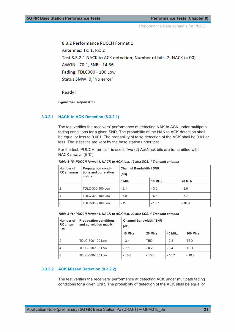
Figure 3-20 shows the report.
Performance Requirements for PUCCH
Performance Tests (Chapter 8)5G NR Base Station Performance Tests
31Application Note (preliminary) 5G NR Base Station Px (DRAFT) ─ GFM315_0e
Figure 3-20: Report 8.3.2
3.3.2.1 NACK to ACK Detection (8.3.2.1)
The test verifies the receivers’ performance at detecting NAK to ACK under multipathfading conditions for a given SNR. The probability of the NAK to ACK detection shallbe equal or less to 0.001. The probability of false detection of the ACK shall be 0.01 orless. The statistics are kept by the base station under test.
For the test, PUCCH format 1 is used. Two (2) AckNack bits are transmitted withNACK always (≡ ‘0’).
Table 3-15: PUCCH format 1, NACK to ACK test, 15 kHz SCS, 1 Transmit antenna
Number ofRX antennas
Propagation condi-tions and correlationmatrix
Channel Bandwidth / SNR
[dB]
5 MHz 10 MHz 20 MHz
2 TDLC-300-100 Low - 3.1 - 3.0 - 3.0
4 TDLC-300-100 Low - 7.8 - 6.8 - 7.7
8 TDLC-300-100 Low - 11.0 - 10.7 - 10.9
Table 3-16: PUCCH format 1, NACK to ACK test, 30 kHz SCS, 1 Transmit antenna
Number ofRX anten-nas
Propagation conditionsand correlation matrix
Channel Bandwidth / SNR
[dB]
10 MHz 20 MHz 40 MHz 100 MHz
2 TDLC-300-100 Low - 3.4 TBD - 2.3 TBD
4 TDLC-300-100 Low - 7.1 - 8.2 - 6.4 TBD
8 TDLC-300-100 Low - 10.8 - 10.6 - 10.7 - 10.8
3.3.2.2 ACK Missed Detection (8.3.2.2)
The test verifies the receivers’ performance at detecting ACK under multipath fadingconditions for a given SNR. The probability of detection of the ACK shall be equal or
Performance Requirements for PUCCH

Performance Tests (Chapter 8)5G NR Base Station Performance Tests
32Application Note (preliminary) 5G NR Base Station Px (DRAFT) ─ GFM315_0e
greater to 0.99. The probability of false detection of the ACK shall be 0.01 or less. Thestatistics are kept by the base station under test.
For the test one bit of information ACK (≡ ‘1’) is transmitted in the PUCCH format 1with following pattern:
Table 3-17: PUCCH format 1, ACK missed test, 15 kHz SCS, 1 Transmit antenna
Number of RXantennas
Propagation condi-tions and correlationmatrix
Channel Bandwidth / SNR
[dB]
5 MHz 10 MHz 20 MHz
2 TDLC-300-100 Low - 4.2 - 3.7 - 4.3
4 TDLC-300-100 Low - 8.0 - 7.4 - 7.9
8 TDLC-300-100 Low - 10.9 - 10.7 - 10.7
Table 3-18: PUCCH format 1, ACK missed test, 30 kHz SCS, 1 Transmit antenna
Number ofRX anten-nas
Propagation conditionsand correlation matrix
Channel Bandwidth / SNR
[dB]
10 MHz 20 MHz 40 MHz 100 MHz
2 TDLC-300-100 Low - 3.4 - 3.8 - 3.8 - 3.7
4 TDLC-300-100 Low - 7.3 - 7.7 - 7.7 - 7.7
8 TDLC-300-100 Low - 10.5 - 10.6 - 10.7 - 10.5
3.3.3 Performance Requirements for PUCCH Format 2
The tests for PUCCH format 1 consist of two tests. The basic settings are the same.The sub-chapters explain the test specialities.
The wanted signal generated by SMW baseband A is split up in two paths (or fourpaths or eight paths). Multipath fading is simulated in the channel simulators, AWGN isadded.
Demo Program
Figure 3-21shows the parameters of the test. The test uses just one Tx Antenna only.The test setting depends on the Test ("8.3.3.1 ACK missed" or "8.3.3.2 UCI BLER").Set the number of Rx Antennas (2, 4 or 8) in the Block Basics. The setting of theSNR is automatically set according to your inputs according to the tables (). For FRCsusing not the full number of resource blocks of the channel bandwidth a special SNRcorrection factor is applied. Please note that not all values are defined yet (TBD), herethe program uses a value of 10 dB. You can set your own parameters by enabling useown parameters (SNR, Fading and AWGN). Please also note that there ar no testsdefined for SCS = 60 kHz, anyhow you can create your own tests.
Performance Requirements for PUCCH

Performance Tests (Chapter 8)5G NR Base Station Performance Tests
33Application Note (preliminary) 5G NR Base Station Px (DRAFT) ─ GFM315_0e
Figure 3-21: Parameter for PUCCH test 8.3.3
Figure 3-22 shows the report.
Figure 3-22: Report 8.3.3
3.3.3.1 ACK Missed Detection (8.3.3.1)
The test verifies the receivers’ performance at detecting ACK under multipath fadingconditions for a given SNR. The probability of detection of the ACK shall be equal orgreater to 0.99. The probability of false detection of the ACK shall be 0.01 or less. Thestatistics are kept by the base station under test.
For the test four (4) bits of information ACK (≡ ‘1111’) are transmitted in the PUCCHformat 2 with following pattern:
Table 3-19 shows the basic parameters.
Table 3-19: Basic parameter PUCCH format 2 ACK missed
Parameter Test
Number of RBs 4
Starting RB 0
Number of Bit 4
Performance Requirements for PUCCH
Performance Tests (Chapter 8)5G NR Base Station Performance Tests
34Application Note (preliminary) 5G NR Base Station Px (DRAFT) ─ GFM315_0e
Parameter Test
Intra-Slot Frequency Hopping enabled
second Hop RB largest RB index - 4
initial Cyclic Shift 0
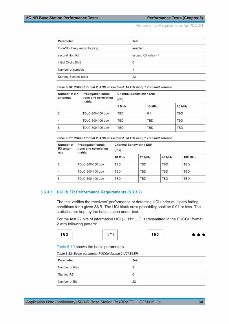
Number of symbols 1
Starting Symbol index 13
Table 3-20: PUCCH format 2, ACK missed test, 15 kHz SCS, 1 Transmit antenna
Number of RXantennas
Propagation condi-tions and correlationmatrix
Channel Bandwidth / SNR
[dB]
5 MHz 10 MHz 20 MHz
2 TDLC-300-100 Low TBD 6.1 TBD
4 TDLC-300-100 Low TBD TBD TBD
8 TDLC-300-100 Low TBD TBD TBD
Table 3-21: PUCCH format 2, ACK missed test, 30 kHz SCS, 1 Transmit antenna
Number ofRX anten-nas
Propagation condi-tions and correlationmatrix
Channel Bandwidth / SNR
[dB]
10 MHz 20 MHz 40 MHz 100 MHz
2 TDLC-300-100 Low TBD TBD TBD TBD
4 TDLC-300-100 Low TBD TBD TBD TBD
8 TDLC-300-100 Low TBD TBD TBD TBD
3.3.3.2 UCI BLER Performance Requirements (8.3.3.2)
The test verifies the receivers’ performance at detecting UCI under multipath fadingconditions for a given SNR. The UCI block error probability shall be 0.01 or less. Thestatistics are kept by the base station under test.
For the test 22 bits of information UCI (≡ ‘1111....’) is transmitted in the PUCCH format2 with following pattern:
Table 3-19 shows the basic parameters.
Table 3-22: Basic parameter PUCCH format 2 UCI BLER
Parameter Test
Number of RBs 9
Starting RB 0
Number of Bit 22
Performance Requirements for PUCCH

Performance Tests (Chapter 8)5G NR Base Station Performance Tests
35Application Note (preliminary) 5G NR Base Station Px (DRAFT) ─ GFM315_0e
Parameter Test
Intra-Slot Frequency Hopping enabled
second Hop RB largest RB index - 9
initial Cyclic Shift 0
Number of symbols 2
Starting Symbol index 12
Table 3-23: PUCCH format 2, UCI BLER test, 15 kHz SCS, 1 Transmit antenna
Number of RXantennas
Propagation condi-tions and correlationmatrix
Channel Bandwidth / SNR
[dB]
5 MHz 10 MHz 20 MHz
2 TDLC-300-100 Low TBD 1.7 TBD
4 TDLC-300-100 Low TBD TBD TBD
8 TDLC-300-100 Low - 6.0 - 5.9 - 5.9
Table 3-24: PUCCH format 2, UCI BLER test, 30 kHz SCS, 1 Transmit antenna
Number ofRX anten-nas
Propagation condi-tions and correlationmatrix
Channel Bandwidth / SNR
[dB]
10 MHz 20 MHz 40 MHz 100 MHz
2 TDLC-300-100 Low TBD TBD 1.0 TBD
4 TDLC-300-100 Low TBD TBD TBD TBD
8 TDLC-300-100 Low TBD TBD TBD TBD
3.3.4 Performance Requirements for PUCCH Format 3 (8.3.4)
The test verifies the receivers’ performance at detecting UCI under multipath fadingconditions for a given SNR. The UCI block error probability shall be 0.01 or less. Thestatistics are kept by the base station under test.
For the test 16 bits of information UCI (≡ '1111....’) is transmitted in the PUCCH format3 with following pattern:
Table 3-25shows the basic parameters.
Table 3-25: Basic parameter PUCCH format 3 UCI BLER
Parameter Test 1 Test 2
Number of RBs 1 3
Starting RB 0 0
Performance Requirements for PUCCH

Performance Tests (Chapter 8)5G NR Base Station Performance Tests
36Application Note (preliminary) 5G NR Base Station Px (DRAFT) ─ GFM315_0e
Parameter Test 1 Test 2
Number of Bit 16 16
Intra-Slot Frequency Hop-ping
enabled enabled
second Hop RB largest RB index - 1 largest RB index - 3
initial Cyclic Shift 0 0
Number of symbols 14 4
Starting Symbol index 0 0
Table 3-26: PUCCH format 3, Test 1, 15 kHz SCS, 1 Transmit antenna
Number ofRX anten-nas
Propagationconditions andcorrelationmatrix
Addi-tionalDMRS
Channel Bandwidth / SNR
[dB]
5 MHz 10 MHz 20 MHz
2 TDLC-300-100Low
✖ TBD 1.7 TBD
✔ TBD 1.1 0.4
4 TDLC-300-100Low
✖ - 3.1 - 2.8 - 3.2
✔ - 3.8 - 3.4 - 3.9
8 TDLC-300-100Low
✖ - 6.4 - 6.1 - 6.2
✔ - 7.1 - 6.9 - 7.1
Table 3-27: PUCCH format 3, Test 2, 15 kHz SCS, 1 Transmit antenna
Number ofRX anten-nas
Propagationconditions andcorrelationmatrix
Addi-tionalDMRS
Channel Bandwidth / SNR
[dB]
5 MHz 10 MHz 20 MHz
2 TDLC-300-100Low
✖ TBD 2.5 TBD
4 TDLC-300-100Low
✖ TBD TBD TBD
8 TDLC-300-100Low
✖ TBD TBD TBD
Table 3-28: PUCCH format 3, Test 1, 30 kHz SCS, 1 Transmit antenna
Numberof RXantennas
Propagation con-ditions and corre-lation matrix
AdditionalDMRS
Channel Bandwidth / SNR
[dB]
10 MHz 20 MHz 40 MHz 100 MHz
2 TDLC-300-100Low
✖ TBD TBD 1.1 TBD
✔ TBD TBD 1.5 TBD
4 TDLC-300-100Low
✖ - 2.3 - 2.8 - 2.7 TBD
✔ - 3.0 - 3.6 - 3.4 TBD
Performance Requirements for PUCCH

Performance Tests (Chapter 8)5G NR Base Station Performance Tests
37Application Note (preliminary) 5G NR Base Station Px (DRAFT) ─ GFM315_0e
Numberof RXantennas
Propagation con-ditions and corre-lation matrix
AdditionalDMRS
Channel Bandwidth / SNR
[dB]
10 MHz 20 MHz 40 MHz 100 MHz
8 TDLC-300-100Low
✖ - 5.8 - 6.0 - 6.2 TBD
✔ - 6.7 - 6.9 - 6.9 TBD
Table 3-29: PUCCH format 3, Test 2, 30 kHz SCS, 1 Transmit antenna
Numberof RXantennas
Propagation con-ditions and corre-lation matrix
AdditionalDMRS
Channel Bandwidth / SNR
[dB]
10 MHz 20 MHz 40 MHz 100 MHz
2 TDLC-300-100Low
✖ TBD TBD 1.5 TBD
4 TDLC-300-100Low
✖ TBD TBD TBD TBD
8 TDLC-300-100Low
✖ TBD TBD TBD TBD
Demo Program
Figure 3-23 shows the parameters of the test. The test uses just one Tx Antenna only.The test settings depend on the Test ("Test 1" or "Test 2") and additional DMRS. Setthe number of Rx Antennas (2, 4 or 8) in the Block Basics. The setting of the SNR isautomatically set according to your inputs according to the tables (). For FRCs usingnot the full number of resource blocks of the channel bandwidth a special SNR correc-tion factor is applied. Please note that not all values are defined yet (TBD), here theprogram uses a value of 10 dB. You can set your own parameters by enabling useown parameters (SNR, Fading and AWGN). Please also note that there ar no testsdefined for SCS = 60 kHz, anyhow you can create your own tests.
Figure 3-23: Parameter for PUCCH test 8.3.4
shows the report.
Performance Requirements for PUCCH
Performance Tests (Chapter 8)5G NR Base Station Performance Tests
38Application Note (preliminary) 5G NR Base Station Px (DRAFT) ─ GFM315_0e
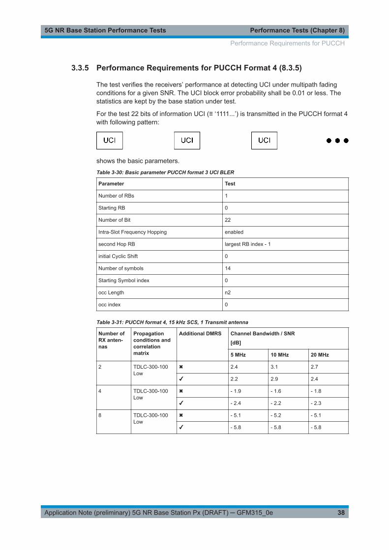
3.3.5 Performance Requirements for PUCCH Format 4 (8.3.5)
The test verifies the receivers’ performance at detecting UCI under multipath fadingconditions for a given SNR. The UCI block error probability shall be 0.01 or less. Thestatistics are kept by the base station under test.
For the test 22 bits of information UCI (≡ ‘1111...’) is transmitted in the PUCCH format 4with following pattern:
shows the basic parameters.
Table 3-30: Basic parameter PUCCH format 3 UCI BLER
Parameter Test
Number of RBs 1
Starting RB 0
Number of Bit 22
Intra-Slot Frequency Hopping enabled
second Hop RB largest RB index - 1
initial Cyclic Shift 0
Number of symbols 14
Starting Symbol index 0
occ Length n2
occ index 0
Table 3-31: PUCCH format 4, 15 kHz SCS, 1 Transmit antenna
Number ofRX anten-nas
Propagationconditions andcorrelationmatrix
Additional DMRS Channel Bandwidth / SNR
[dB]
5 MHz 10 MHz 20 MHz
2 TDLC-300-100Low
✖ 2.4 3.1 2.7
✔ 2.2 2.9 2.4
4 TDLC-300-100Low
✖ - 1.9 - 1.6 - 1.8
✔ - 2.4 - 2.2 - 2.3
8 TDLC-300-100Low
✖ - 5.1 - 5.2 - 5.1
✔ - 5.8 - 5.8 - 5.8
Performance Requirements for PUCCH

Performance Tests (Chapter 8)5G NR Base Station Performance Tests
39Application Note (preliminary) 5G NR Base Station Px (DRAFT) ─ GFM315_0e
Table 3-32: PUCCH format 4, 30 kHz SCS, 1 Transmit antenna
Numberof RXantennas
Propagation con-ditions and corre-lation matrix
AdditionalDMRS
Channel Bandwidth / SNR
[dB]
10 MHz 20 MHz 40 MHz 100 MHz
2 TDLC-300-100Low
✖ 3.8 2.9 3.7 TBD
✔ 3.6 2.9 3.4 TBD
4 TDLC-300-100Low
✖ - 0.9 - 1.5 - 1.3 TBD
✔ - 1.5 - 2.0 - 2.0 TBD
8 TDLC-300-100Low
✖ - 4.7 - 4.9 - 5.0 TBD
✔ - 5.3 - 5.5 - 5.8 TBD
Demo Program
Figure 3-24 shows the parameters of the test. The test uses just one Tx Antenna only.The test settings depend on the additional DMRS. Set the number of Rx Antennas(2, 4 or 8) in the Block Basics. The setting of the SNR is automatically set according toyour inputs according to the tables (). For FRCs using not the full number of resourceblocks of the channel bandwidth a special SNR correction factor is applied. Pleasenote that not all values are defined yet (TBD), here the program uses a value of 10 dB.You can set your own parameters by enabling use own parameters (SNR, Fading andAWGN). Please also note that there ar no tests defined for SCS = 60 kHz, anyhow youcan create your own tests.
Figure 3-24: Parameter for PUCCH test 8.3.5
shows the report.
3.4 Performance Requirements for PRACH
3.4.1 PRACH False Alarm Probability and Missed Detection (8.4.1)
This test is not implemented yet.
Performance Requirements for PRACH

Appendix5G NR Base Station Performance Tests
40Application Note (preliminary) 5G NR Base Station Px (DRAFT) ─ GFM315_0e
4 Appendix
4.1 R&S QuickStep
The QuickStep software application makes it possible to combine tests (modules) pro-vided by Rohde & Schwarz into test plans to allow rapid and easy remote control oftest instruments. The program needs a R&S License. The testmoduls for 5G NR Base-station tests are free of charge.
Requirements
Operating system:
● Windows 10● Windows 8.1● Microsoft Windows 7 (64 bit,SP1, universal C runtime)
General PC requirements: Standard PC
Remote control interface:
● R&S® VISA● LAN connection
First Steps
Please use the provided TestProcedure as a first step. This allows you to skip verybasic settings.
R&S QuickStep

Appendix5G NR Base Station Performance Tests
41Application Note (preliminary) 5G NR Base Station Px (DRAFT) ─ GFM315_0e
Figure 4-1: QuickStep with Performance Tests
You can find all 5G NR Basestation Performance Tests on the left side under BlockLibrary NR_BS_Performance Tests. In the middle underTest Procedure, you can findthe active Testsequence.
You can create your own Test Procedure by using drag-and-drop of the available stepsin the Block Library into the TestProcedure part. Please make sure to connect the bot-tom port of a block to the top port of the next block.
To start a Test, go to the tab TestPlan Editor and click on the Arrow Single Run.
Figure 4-2: Run a test
After the execution run, you can find the results under the tab Results Viewer.
R&S QuickStep

Appendix5G NR Base Station Performance Tests
42Application Note (preliminary) 5G NR Base Station Px (DRAFT) ─ GFM315_0e
Figure 4-3: Report and Protocol
A click on Report1.pdf opens the Report on the last run.
ExecutionProtocol shows a protocol of the last run which all messages from Quick-step and the sent and received SCPI interactions.
4.2 References
[1] 3GPP Technical Specification Group Radio Access Network; NR Base station con-formance testing, Part 1: Conducted conformance testing, Release 15; 3GPP TS38.141-1, V 15.1.0, March 2019
[2] 3GPP Technical Specification Group Radio Access Network; NR Base station con-formance testing, Part 2: Radiated conformance testing, Release 15; 3GPP TS38.141-2, V 15.1.0, March 2019
[3] 3GPP Technical Specification Group Radio Access Network; NR Base station Radiotransmission and reception, Release 15; 3GPP TS 38.104, V 15.4.0, December 2018
[4] Rohde & Schwarz, 5G NR Technology Introduction, March 2019
[5] Rohde & Schwarz,QuickStep Test Executive Software: User Manual, Version 10,2018
4.3 Additional Information
Please send your comments and suggestions regarding this application note to
Additional Information

Appendix5G NR Base Station Performance Tests
43Application Note (preliminary) 5G NR Base Station Px (DRAFT) ─ GFM315_0e
4.4 Ordering Information
Please visit the Rohde & Schwarz product websites at www.rohde-schwarz.com forordering information on the following Rohde & Schwarz products or contact your localRohde & Schwarz sales office for further assistance.
Vector signal generators
● SMW200A vector signal generator
Ordering Information

Rohde & Schwarz5G NR Base Station Performance Tests
44Application Note (preliminary) 5G NR Base Station Px (DRAFT) ─ GFM315_0e
5 Rohde & SchwarzThe Rohde & Schwarz electronics group offers innovative solutions in the followingbusiness fields: test and measurement, broadcast and media, secure communications,cybersecurity, monitoring and network testing. Founded more than 80 years ago, theindependent company has an extensive sales and service network with locations inmore than 70 countries.
The electronics group ranks among the world market leaders in its established busi-ness fields. The company is headquartered in Munich, Germany. It also has regionalheadquarters in Singapore and Columbia, Maryland, USA, to manage its operations inthese regions.
Sustainable product design
● Environmental compatibility and eco-footprint● Energy efficiency and low emissions● Longevity and optimized total cost of ownership
Certified Quality Management
ISO 9001Certified Environmental Management
ISO 14001
Contact us
● Europe, Africa, Middle East | [email protected]+49 89 4129 12345
● North America | [email protected] (1-888-837-8772)
● Latin America | [email protected]+1-410-910-7988
● Asia Pacific | [email protected]+65 65 13 04 88
● China | [email protected]+86-800-810-8228 / +86-400-650-5896
Rohde & Schwarz GmbH & Co. KG
Mühldorfstraße 15 | D - 81671 München
+ 49 89 4129 - 0 | Fax + 49 89 4129 – 13777
www.rohde-schwarz.com
This application note and the supplied programs may only be used subject to observance of the conditionsof use set forth in the download area of the Rohde & Schwarz website.
R&S® is a registered trademark of Rohde & Schwarz GmbH & Co. KG. Trade names are trademarks oftheir owners.