Embed Size (px)
Citation preview
Highlight Lines for Conveying Shape
Doug DeCarloRutgers University
Szymon RusinkiewiczPrinceton University
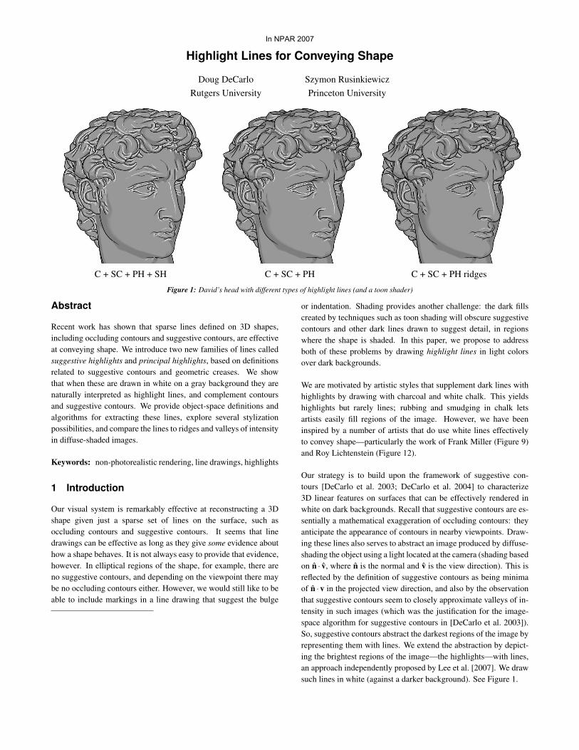
C + SC + PH + SH C + SC + PH C + SC + PH ridges
Figure 1: David’s head with different types of highlight lines (and a toon shader)
Abstract
Recent work has shown that sparse lines defined on 3D shapes,including occluding contours and suggestive contours, are effectiveat conveying shape. We introduce two new families of lines calledsuggestive highlights and principal highlights, based on definitionsrelated to suggestive contours and geometric creases. We showthat when these are drawn in white on a gray background they arenaturally interpreted as highlight lines, and complement contoursand suggestive contours. We provide object-space definitions andalgorithms for extracting these lines, explore several stylizationpossibilities, and compare the lines to ridges and valleys of intensityin diffuse-shaded images.
Keywords: non-photorealistic rendering, line drawings, highlights
1 Introduction
Our visual system is remarkably effective at reconstructing a 3Dshape given just a sparse set of lines on the surface, such asoccluding contours and suggestive contours. It seems that linedrawings can be effective as long as they give some evidence abouthow a shape behaves. It is not always easy to provide that evidence,however. In elliptical regions of the shape, for example, there areno suggestive contours, and depending on the viewpoint there maybe no occluding contours either. However, we would still like to beable to include markings in a line drawing that suggest the bulge
or indentation. Shading provides another challenge: the dark fillscreated by techniques such as toon shading will obscure suggestivecontours and other dark lines drawn to suggest detail, in regionswhere the shape is shaded. In this paper, we propose to addressboth of these problems by drawing highlight lines in light colorsover dark backgrounds.
We are motivated by artistic styles that supplement dark lines withhighlights by drawing with charcoal and white chalk. This yieldshighlights but rarely lines; rubbing and smudging in chalk letsartists easily fill regions of the image. However, we have beeninspired by a number of artists that do use white lines effectivelyto convey shape—particularly the work of Frank Miller (Figure 9)and Roy Lichtenstein (Figure 12).
Our strategy is to build upon the framework of suggestive con-tours [DeCarlo et al. 2003; DeCarlo et al. 2004] to characterize3D linear features on surfaces that can be effectively rendered inwhite on dark backgrounds. Recall that suggestive contours are es-sentially a mathematical exaggeration of occluding contours: theyanticipate the appearance of contours in nearby viewpoints. Draw-ing these lines also serves to abstract an image produced by diffuse-shading the object using a light located at the camera (shading basedon n · v, where n is the normal and v is the view direction). This isreflected by the definition of suggestive contours as being minimaof n ·v in the projected view direction, and also by the observationthat suggestive contours seem to closely approximate valleys of in-tensity in such images (which was the justification for the image-space algorithm for suggestive contours in [DeCarlo et al. 2003]).So, suggestive contours abstract the darkest regions of the image byrepresenting them with lines. We extend the abstraction by depict-ing the brightest regions of the image—the highlights—with lines,an approach independently proposed by Lee et al. [2007]. We drawsuch lines in white (against a darker background). See Figure 1.
In NPAR 2007
In this paper, we argue that highlight lines are described bytwo types of lines: suggestive highlights (which appear at view-dependent inflections) and principal highlights (which appear whenthe surface is viewed along a principal curvature direction). We willdemonstrate that these lines are maxima of n · v in specific direc-tions, and present definitions of these lines in terms of local surfacegeometry. We continue by describing algorithms for their extrac-tion, and effective rendering styles that include them.
2 Related Work
Our approach defines new geometric linear features of the surface.There are a number of such lines that serve as ingredients innon-photorealistic renderings of shape. They include occludingcontours (interior and exterior silhouettes — locations at which thesurface normal is perpendicular to the view direction) [Elber andCohen 1990; Winkenbach and Salesin 1994; Markosian et al. 1997;Hertzmann and Zorin 2000], sharp creases [Gooch et al. 1999;Markosian et al. 1997; Saito and Takahashi 1990], ridge and valleylines (local maxima of principal curvature magnitude in a principaldirection) [Interrante et al. 1995; Thirion and Gourdon 1996; Paulyet al. 2003; Ohtake et al. 2004], apparent ridges (variants ofgeometric ridges that include a view-dependent projection) [Juddet al. 2007], and suggestive contours (locations at which occludingcontours appear with minimal change in viewpoint) [DeCarlo et al.2003; DeCarlo et al. 2004]. Such lines are typically drawnin black on a lighter background, although they are sometimesdrawn in white. For instance, sharp creases that are not on thecontour are drawn in white by Gooch et al. [1999] to depicthighlights. To our knowledge, the two new types of highlight linesdefined here represent the first such object-space description ofthese lines on smooth surfaces. Other styles are possible as well,including non-photorealistic illustration of specular reflections ofthe environment [Weidenbacher et al. 2006].
We also compare our results to an image-space algorithm that worksfrom a rendered image, an approach related to the image-space anddepth-buffer processing performed by Saito and Takahashi [1990],the image-space algorithm for suggestive contours [DeCarlo et al.2003], and the GPU algorithm of Lee et al. [2007]. This is alsorelated to processing of photographs into line drawings [Pearsonand Robinson 1985; Iverson and Zucker 1995].
3 Highlight Lines
This section assumes familiarity with the definitions of suggestivecontours [DeCarlo et al. 2003], although some material is summa-rized here. We start by defining the contour and suggestive contour.
Consider a smooth, closed surface that is viewed from a point c.For any point p on the surface, the viewing direction is defined asv = c−p. The occluding contour [Cipolla and Giblin 2000] is theboundary between the visible and hidden parts of the surface. It isgenerated by the set of points where the surface is viewed edge-on,where the normal vector n is perpendicular to the viewing direction:
n · v = 0. (1)
v
C
C
SH
SC
PH+
PH-
SC
SC
PH+
PH-
SH
SC
SC
PH+
PH+
SC
contour
suggestive contour
suggestive highlight
principal highlight
(+ = ridge - = valley)
C
SC
SH
PH
front-facing back-facing
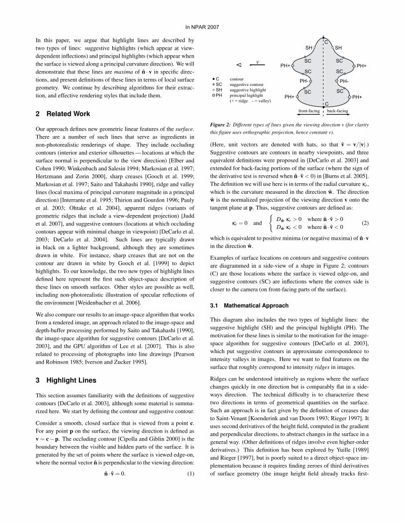
Figure 2: Different types of lines given the viewing direction v (for claritythis figure uses orthographic projection, hence constant v).
(Here, unit vectors are denoted with hats, so that v = v/|v|.)Suggestive contours are contours in nearby viewpoints, and threeequivalent definitions were proposed in [DeCarlo et al. 2003] andextended for back-facing portions of the surface (where the sign ofthe derivative test is reversed when n · v < 0) in [Burns et al. 2005].The definition we will use here is in terms of the radial curvature κr,which is the curvature measured in the direction w. The directionw is the normalized projection of the viewing direction v onto thetangent plane at p. Thus, suggestive contours are defined as:
κr = 0 and
{Dw κr > 0 where n · v > 0Dw κr < 0 where n · v < 0
(2)
which is equivalent to positive minima (or negative maxima) of n ·vin the direction w.
Examples of surface locations on contours and suggestive contoursare diagrammed in a side-view of a shape in Figure 2; contours(C) are those locations where the surface is viewed edge-on, andsuggestive contours (SC) are inflections where the convex side iscloser to the camera (on front-facing parts of the surface).
3.1 Mathematical Approach
This diagram also includes the two types of highlight lines: thesuggestive highlight (SH) and the principal highlight (PH). Themotivation for these lines is similar to the motivation for the image-space algorithm for suggestive contours [DeCarlo et al. 2003],which put suggestive contours in approximate correspondence tointensity valleys in images. Here we want to find features on thesurface that roughly correspond to intensity ridges in images.
Ridges can be understood intuitively as regions where the surfacechanges quickly in one direction but is comparably flat in a side-ways direction. The technical difficulty is to characterize thesetwo directions in terms of geometrical quantities on the surface.Such an approach is in fact given by the definition of creases dueto Saint-Venant [Koenderink and van Doorn 1993; Rieger 1997]. Ituses second derivatives of the height field, computed in the gradientand perpendicular directions, to abstract changes in the surface in ageneral way. (Other definitions of ridges involve even higher-orderderivatives.) This definition has been explored by Yuille [1989]and Rieger [1997], but is poorly suited to a direct object-space im-plementation because it requires finding zeroes of third derivativesof surface geometry (the image height field already tracks first-
In NPAR 2007
derivative changes in the surface through n). What we will do in-stead is to attempt to catch most of the meaningful image ridges bylooking for places where intensity changes quickly along either ofthe two natural directions for exploring a viewed surface: w, theprojection of the view direction into the tangent plane of the sur-face; and w⊥ , the perpendicular to w in the tangent plane. The firstcase leads to lines we call suggestive highlights, while the secondcase leads to lines we call principal highlights. These definitionsprove simple enough to implement but are sufficiently grounded inthe mathematics of shape to convey highlights effectively1.
3.2 Suggestive Highlights
Suggestive highlights are complementary to suggestive contours:they are positive maxima (or negative minima) of n · v in thedirection w. Equivalently, these are locations at which:
κr = 0 and
{Dw κr < 0 where n · v > 0Dw κr > 0 where n · v < 0
. (3)
(This is based on a derivation that is similar to that of suggestivecontours.) In Figure 2 these points are labeled SH, and accountfor the remaining view-dependent inflections on the shape. Thus,suggestive highlights are simply the “other” part of the solution setof κr = 0. We will see in Section 5 how both suggestive contoursand highlights can be used effectively in the same line drawing.
3.3 Principal Highlights
Principal highlights (PH) are strong positive maxima (or negativeminima) of n · v in the direction w⊥ . The direction w⊥ = n× wsits perpendicular to w in the tangent plane [DeCarlo et al. 2004].Deriving a definition of PH in terms of second derivative quantitiesis achieved by differentiating n · v in the direction w⊥ and settingit equal to zero. Maxima occur where the second derivative in thisdirection is negative.
The derivation proceeds along similar lines to that in [DeCarlo et al.2003]. Beginning with the condition for extrema, locations whereDw⊥(n ·v) = 0, we can show that Dw⊥(n ·v) = (Dw⊥n) ·v+ n ·Dw⊥v =II(w⊥) · v + 0 = II(w, w⊥) = τr|w|, where τr is the radial torsion[DeCarlo et al. 2004]—the geodesic torsion in the direction w.For the time being, if we disregard locations where n and v areparallel (where w = 0), then it follows that principal highlights arein locations where τr = 0 and Dw⊥τr < 0 (on front-facing parts ofthe shape).
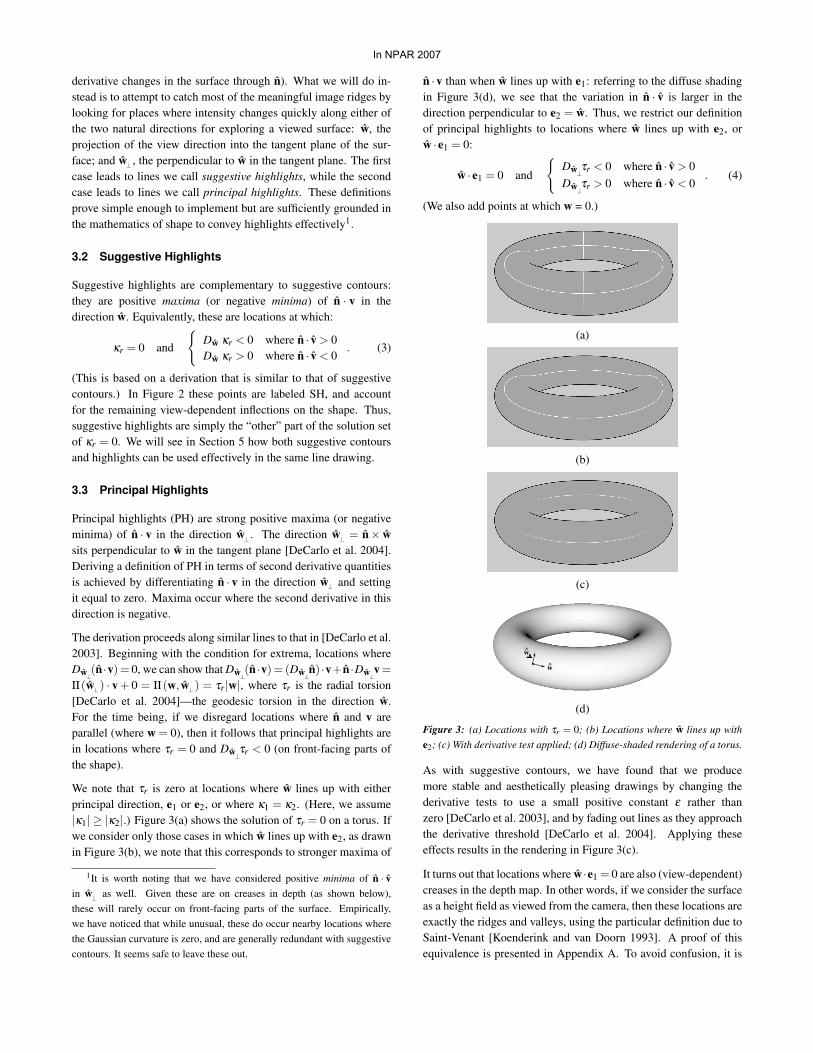
We note that τr is zero at locations where w lines up with eitherprincipal direction, e1 or e2, or where κ1 = κ2. (Here, we assume|κ1| ≥ |κ2|.) Figure 3(a) shows the solution of τr = 0 on a torus. Ifwe consider only those cases in which w lines up with e2, as drawnin Figure 3(b), we note that this corresponds to stronger maxima of
1It is worth noting that we have considered positive minima of n · vin w⊥ as well. Given these are on creases in depth (as shown below),these will rarely occur on front-facing parts of the surface. Empirically,we have noticed that while unusual, these do occur nearby locations wherethe Gaussian curvature is zero, and are generally redundant with suggestivecontours. It seems safe to leave these out.
n ·v than when w lines up with e1: referring to the diffuse shadingin Figure 3(d), we see that the variation in n · v is larger in thedirection perpendicular to e2 = w. Thus, we restrict our definitionof principal highlights to locations where w lines up with e2, orw · e1 = 0:
w · e1 = 0 and
{Dw⊥τr < 0 where n · v > 0Dw⊥τr > 0 where n · v < 0
. (4)
(We also add points at which w = 0.)
(a)
(b)
(c)
w
w
(d)
Figure 3: (a) Locations with τr = 0; (b) Locations where w lines up withe2; (c) With derivative test applied; (d) Diffuse-shaded rendering of a torus.
As with suggestive contours, we have found that we producemore stable and aesthetically pleasing drawings by changing thederivative tests to use a small positive constant ε rather thanzero [DeCarlo et al. 2003], and by fading out lines as they approachthe derivative threshold [DeCarlo et al. 2004]. Applying theseeffects results in the rendering in Figure 3(c).
It turns out that locations where w ·e1 = 0 are also (view-dependent)creases in the depth map. In other words, if we consider the surfaceas a height field as viewed from the camera, then these locations areexactly the ridges and valleys, using the particular definition due toSaint-Venant [Koenderink and van Doorn 1993]. A proof of thisequivalence is presented in Appendix A. To avoid confusion, it is
In NPAR 2007
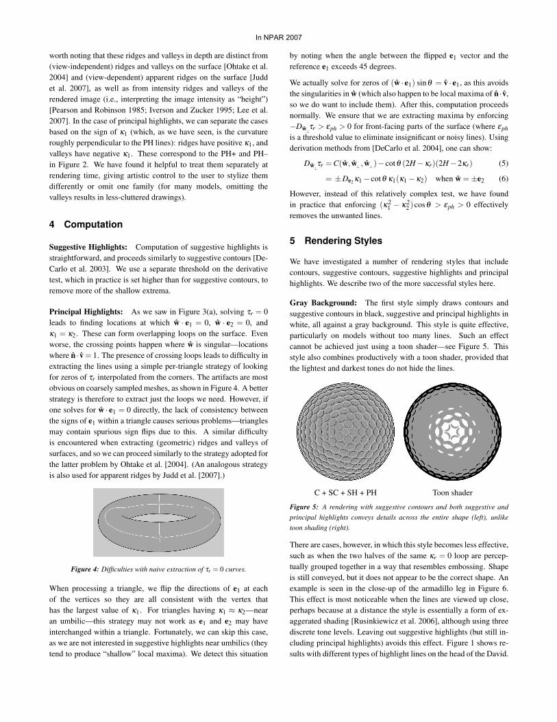
worth noting that these ridges and valleys in depth are distinct from(view-independent) ridges and valleys on the surface [Ohtake et al.2004] and (view-dependent) apparent ridges on the surface [Juddet al. 2007], as well as from intensity ridges and valleys of therendered image (i.e., interpreting the image intensity as “height”)[Pearson and Robinson 1985; Iverson and Zucker 1995; Lee et al.2007]. In the case of principal highlights, we can separate the casesbased on the sign of κ1 (which, as we have seen, is the curvatureroughly perpendicular to the PH lines): ridges have positive κ1, andvalleys have negative κ1. These correspond to the PH+ and PH–in Figure 2. We have found it helpful to treat them separately atrendering time, giving artistic control to the user to stylize themdifferently or omit one family (for many models, omitting thevalleys results in less-cluttered drawings).
4 Computation
Suggestive Highlights: Computation of suggestive highlights isstraightforward, and proceeds similarly to suggestive contours [De-Carlo et al. 2003]. We use a separate threshold on the derivativetest, which in practice is set higher than for suggestive contours, toremove more of the shallow extrema.
Principal Highlights: As we saw in Figure 3(a), solving τr = 0leads to finding locations at which w · e1 = 0, w · e2 = 0, andκ1 = κ2. These can form overlapping loops on the surface. Evenworse, the crossing points happen where w is singular—locationswhere n · v = 1. The presence of crossing loops leads to difficulty inextracting the lines using a simple per-triangle strategy of lookingfor zeros of τr interpolated from the corners. The artifacts are mostobvious on coarsely sampled meshes, as shown in Figure 4. A betterstrategy is therefore to extract just the loops we need. However, ifone solves for w · e1 = 0 directly, the lack of consistency betweenthe signs of e1 within a triangle causes serious problems—trianglesmay contain spurious sign flips due to this. A similar difficultyis encountered when extracting (geometric) ridges and valleys ofsurfaces, and so we can proceed similarly to the strategy adopted forthe latter problem by Ohtake et al. [2004]. (An analogous strategyis also used for apparent ridges by Judd et al. [2007].)
Figure 4: Difficulties with naive extraction of τr = 0 curves.
When processing a triangle, we flip the directions of e1 at eachof the vertices so they are all consistent with the vertex thathas the largest value of κ1. For triangles having κ1 ≈ κ2—nearan umbilic—this strategy may not work as e1 and e2 may haveinterchanged within a triangle. Fortunately, we can skip this case,as we are not interested in suggestive highlights near umbilics (theytend to produce “shallow” local maxima). We detect this situation
by noting when the angle between the flipped e1 vector and thereference e1 exceeds 45 degrees.
We actually solve for zeros of (w · e1) sinθ = v · e1, as this avoidsthe singularities in w (which also happen to be local maxima of n · v,so we do want to include them). After this, computation proceedsnormally. We ensure that we are extracting maxima by enforcing−Dw⊥τr > εph > 0 for front-facing parts of the surface (where εphis a threshold value to eliminate insignificant or noisy lines). Usingderivation methods from [DeCarlo et al. 2004], one can show:
Dw⊥τr = C(w, w⊥ , w⊥)− cotθ (2H−κr)(2H−2κr) (5)
= ±De2 κ1− cotθ κ1(κ1−κ2) when w =±e2 (6)
However, instead of this relatively complex test, we have foundin practice that enforcing (κ2
1 − κ22 )cosθ > εph > 0 effectively
removes the unwanted lines.
5 Rendering Styles
We have investigated a number of rendering styles that includecontours, suggestive contours, suggestive highlights and principalhighlights. We describe two of the more successful styles here.
Gray Background: The first style simply draws contours andsuggestive contours in black, suggestive and principal highlights inwhite, all against a gray background. This style is quite effective,particularly on models without too many lines. Such an effectcannot be achieved just using a toon shader—see Figure 5. Thisstyle also combines productively with a toon shader, provided thatthe lightest and darkest tones do not hide the lines.
C + SC + SH + PH Toon shader
Figure 5: A rendering with suggestive contours and both suggestive andprincipal highlights conveys details across the entire shape (left), unliketoon shading (right).
There are cases, however, in which this style becomes less effective,such as when the two halves of the same κr = 0 loop are percep-tually grouped together in a way that resembles embossing. Shapeis still conveyed, but it does not appear to be the correct shape. Anexample is seen in the close-up of the armadillo leg in Figure 6.This effect is most noticeable when the lines are viewed up close,perhaps because at a distance the style is essentially a form of ex-aggerated shading [Rusinkiewicz et al. 2006], although using threediscrete tone levels. Leaving out suggestive highlights (but still in-cluding principal highlights) avoids this effect. Figure 1 shows re-sults with different types of highlight lines on the head of the David.
In NPAR 2007
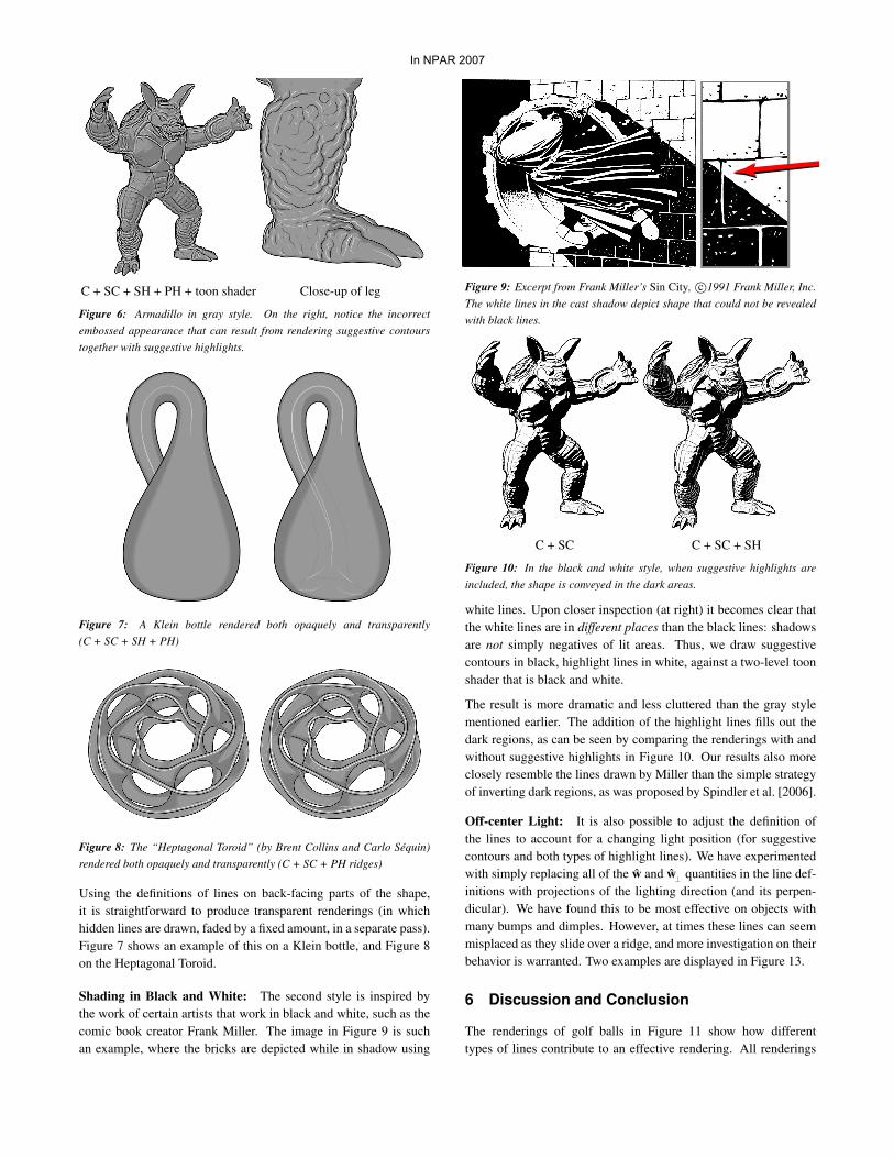
C + SC + SH + PH + toon shader Close-up of leg
Figure 6: Armadillo in gray style. On the right, notice the incorrectembossed appearance that can result from rendering suggestive contourstogether with suggestive highlights.
Figure 7: A Klein bottle rendered both opaquely and transparently(C + SC + SH + PH)
Figure 8: The “Heptagonal Toroid” (by Brent Collins and Carlo Sequin)rendered both opaquely and transparently (C + SC + PH ridges)
Using the definitions of lines on back-facing parts of the shape,it is straightforward to produce transparent renderings (in whichhidden lines are drawn, faded by a fixed amount, in a separate pass).Figure 7 shows an example of this on a Klein bottle, and Figure 8on the Heptagonal Toroid.
Shading in Black and White: The second style is inspired bythe work of certain artists that work in black and white, such as thecomic book creator Frank Miller. The image in Figure 9 is suchan example, where the bricks are depicted while in shadow using
Figure 9: Excerpt from Frank Miller’s Sin City, c©1991 Frank Miller, Inc.The white lines in the cast shadow depict shape that could not be revealedwith black lines.
C + SC C + SC + SH
Figure 10: In the black and white style, when suggestive highlights areincluded, the shape is conveyed in the dark areas.
white lines. Upon closer inspection (at right) it becomes clear thatthe white lines are in different places than the black lines: shadowsare not simply negatives of lit areas. Thus, we draw suggestivecontours in black, highlight lines in white, against a two-level toonshader that is black and white.
The result is more dramatic and less cluttered than the gray stylementioned earlier. The addition of the highlight lines fills out thedark regions, as can be seen by comparing the renderings with andwithout suggestive highlights in Figure 10. Our results also moreclosely resemble the lines drawn by Miller than the simple strategyof inverting dark regions, as was proposed by Spindler et al. [2006].
Off-center Light: It is also possible to adjust the definition ofthe lines to account for a changing light position (for suggestivecontours and both types of highlight lines). We have experimentedwith simply replacing all of the w and w⊥ quantities in the line def-initions with projections of the lighting direction (and its perpen-dicular). We have found this to be most effective on objects withmany bumps and dimples. However, at times these lines can seemmisplaced as they slide over a ridge, and more investigation on theirbehavior is warranted. Two examples are displayed in Figure 13.
6 Discussion and Conclusion
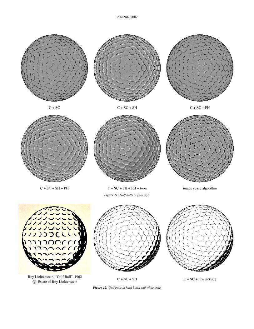
The renderings of golf balls in Figure 11 show how differenttypes of lines contribute to an effective rendering. All renderings
In NPAR 2007
include contours and suggestive contours, and the first row showssuggestive highlights rendered separately from principal highlights.The second row shows the effects when these lines are combined,first with a solid gray background, and then with a light toon shader.
Figure 12 shows a comparison between the painting “Golf Ball” byRoy Lichtenstein and renderings produced by our system. Whileour system does not reproduce all of the interesting aspects ofdesign and stylization in this work, there are similarities: the upperpart of the painting has lines that abstract dark areas, while inthe shadow the lines abstract light areas. This compares wellto a rendering in our black and white style, using suggestivecontours in the light and suggestive highlights in the shadow. Itis worth comparing the orientation of the curved lines that depictthe dimples—they are the same in our rendering as in the painting.In contrast, we can simply draw suggestive contours in white inthe shadowed areas (labeled inverse(SC) in the figure), which iscomparable to the approach of Spindler et al. [2006]. This produceslines that disagree with Lichtenstein’s and lead to a conflicted andineffective rendering. We believe that this comparison provides oneof the strongest arguments for this work.
Although SH and PH lines are not defined explicitly in terms ofintensity ridges in the image, we have empirically observed thatthey typically occur near such ridges (much as suggestive contourstypically occur near intensity valleys). We have adapted the image-space algorithm described by DeCarlo et al. [2003] for suggestivecontours to extract both ridges and valleys of a diffusely renderedimage. The changes are straightforward, with perhaps the mostsubstantial being that the rendered diffuse images use 1
2 + 12 (n · l),
so that lines can still be extracted from locations in shadow. Theresults of the image space algorithm are provided for the golf ball—in Figure 11, and in Figure 13 with an off-center light. We believethat a better theoretical understanding of this relationship is inorder, though this is future work.
In summary, we have presented two new types of lines that conveyhighlights—suggestive highlights and principal highlights. Thelines are defined in a way that extends the concept of suggestivecontours to local maxima of n · v, in the w and w⊥ directions. Thelines can be effectively used in different styles, augmenting existinglines to convey more information about surface geometry.
Acknowledgments
We thank Hamilton Chong, Adam Finkelstein, Steven Gortler,Xiaofeng Mi, Manish Singh and Matthew Stone for their insightsand helpful conversations. 3D models in this paper are courtesyof Stanford University, the Digital Michelangelo Project, and UCBerkeley, while Figure 12(left) is c©Estate of Roy Lichtenstein, andFigure 9 is c©Frank Miller, Inc. This work is partially supportedby the National Science Foundation through grants CCF-0541185,CCF-0347427, and IIS-0511965, as well as the Sloan Foundation.
References
BURNS, M., KLAWE, J., RUSINKIEWICZ, S., FINKELSTEIN,A., AND DECARLO, D. 2005. Line drawings from volume
data. ACM Transactions on Graphics (Proc. SIGGRAPH) 24, 3(Aug.), 512–518.
CIPOLLA, R., AND GIBLIN, P. J. 2000. Visual Motion of Curvesand Surfaces. Cambridge University Press.
DECARLO, D., FINKELSTEIN, A., RUSINKIEWICZ, S., AND
SANTELLA, A. 2003. Suggestive contours for conveying shape.ACM Transactions on Graphics (Proc. SIGGRAPH) 22, 3, 848–855.
DECARLO, D., FINKELSTEIN, A., AND RUSINKIEWICZ, S. 2004.Interactive rendering of suggestive contours with temporal co-herence. In NPAR 2004: Proceedings of the 3rd interna-tional symposium on Non-photorealistic animation and render-ing, ACM Press, New York, NY, USA, 15–145.
ELBER, G., AND COHEN, E. 1990. Hidden curve removalfor free form surfaces. In Computer Graphics (Proceedings ofSIGGRAPH 90), 95–104.
GOOCH, B., SLOAN, P.-P. J., GOOCH, A., SHIRLEY, P., AND
RIESENFELD, R. 1999. Interactive technical illustration. InSI3D ’99: Proceedings of the 1999 symposium on Interactive3D graphics, ACM Press, New York, NY, USA, 31–38.
HERTZMANN, A., AND ZORIN, D. 2000. Illustrating smoothsurfaces. In Proceedings of ACM SIGGRAPH 2000, ComputerGraphics Proceedings, Annual Conference Series, 517–526.
INTERRANTE, V., FUCHS, H., AND PIZER, S. 1995. Enhancingtransparent skin surfaces with ridge and valley lines. In Proceed-ings of the 6th conference on Visualization ’95, IEEE ComputerSociety, Washington, DC, USA, 52–59.
IVERSON, L. A., AND ZUCKER, S. W. 1995. Logical/linearoperators for image curves. IEEE Transactions on PatternAnalysis and Machine Intelligence 17, 10, 982–996.
JUDD, T., DURAND, F., AND ADELSON, E. 2007. Apparentridges for line drawing. ACM Transactions on Graphics (Proc.SIGGRAPH) 26, 3, Article 19.
KOENDERINK, J., AND VAN DOORN, A. 1993. Local features ofsmooth shapes: Ridges and courses. Proceedings of the SPIE2031, 2–13.
LEE, Y., MARKOSIAN, L., LEE, S., AND HUGHES, J. F. 2007.Line drawings via abstracted shading. ACM Transactions onGraphics (Proc. SIGGRAPH) 26, 3, Article 18.
MARKOSIAN, L., KOWALSKI, M. A., GOLDSTEIN, D.,TRYCHIN, S. J., HUGHES, J. F., AND BOURDEV, L. D. 1997.Real-time nonphotorealistic rendering. In SIGGRAPH ’97: Pro-ceedings of the 24th annual conference on Computer graphicsand interactive techniques, ACM Press/Addison-Wesley Pub-lishing Co., New York, NY, USA, 415–420.
OHTAKE, Y., BELYAEV, A., AND SEIDEL, H.-P. 2004. Ridge-valley lines on meshes via implicit surface fitting. ACM Trans-actions on Graphics 23, 3 (Aug.), 609–612.
PAULY, M., KEISER, R., AND GROSS, M. 2003. Multi-scale feature extraction on point-sampled surfaces. ComputerGraphics Forum 22, 3 (Sept.), 281–290.
In NPAR 2007
C + SC C + SC + SH C + SC + PH
C + SC + SH + PH C + SC + SH + PH + toon image space algorithm
Figure 11: Golf balls in gray style
Roy Lichtenstein, “Golf Ball”, 1962c© Estate of Roy Lichtenstein
C + SC + SH C + SC + inverse(SC)
Figure 12: Golf balls in hard black and white style.
In NPAR 2007
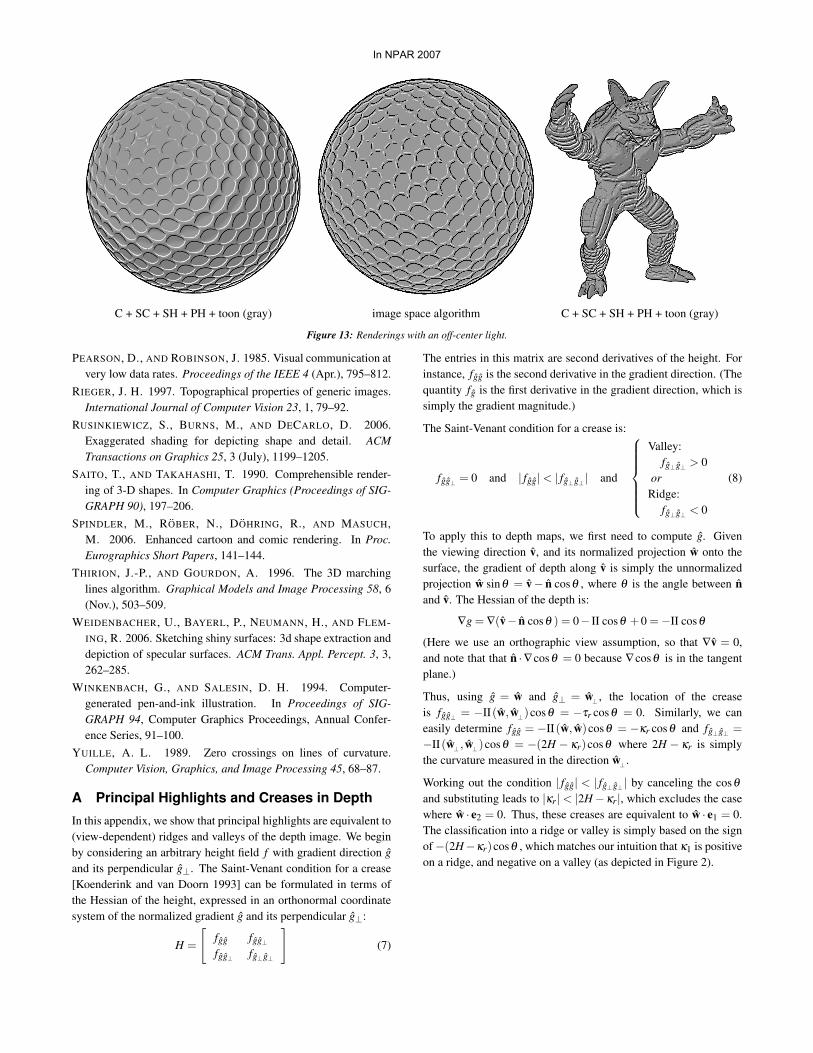
C + SC + SH + PH + toon (gray) image space algorithm C + SC + SH + PH + toon (gray)
Figure 13: Renderings with an off-center light.
PEARSON, D., AND ROBINSON, J. 1985. Visual communication atvery low data rates. Proceedings of the IEEE 4 (Apr.), 795–812.
RIEGER, J. H. 1997. Topographical properties of generic images.International Journal of Computer Vision 23, 1, 79–92.
RUSINKIEWICZ, S., BURNS, M., AND DECARLO, D. 2006.Exaggerated shading for depicting shape and detail. ACMTransactions on Graphics 25, 3 (July), 1199–1205.
SAITO, T., AND TAKAHASHI, T. 1990. Comprehensible render-ing of 3-D shapes. In Computer Graphics (Proceedings of SIG-GRAPH 90), 197–206.
SPINDLER, M., ROBER, N., DOHRING, R., AND MASUCH,M. 2006. Enhanced cartoon and comic rendering. In Proc.Eurographics Short Papers, 141–144.
THIRION, J.-P., AND GOURDON, A. 1996. The 3D marchinglines algorithm. Graphical Models and Image Processing 58, 6(Nov.), 503–509.
WEIDENBACHER, U., BAYERL, P., NEUMANN, H., AND FLEM-ING, R. 2006. Sketching shiny surfaces: 3d shape extraction anddepiction of specular surfaces. ACM Trans. Appl. Percept. 3, 3,262–285.
WINKENBACH, G., AND SALESIN, D. H. 1994. Computer-generated pen-and-ink illustration. In Proceedings of SIG-GRAPH 94, Computer Graphics Proceedings, Annual Confer-ence Series, 91–100.
YUILLE, A. L. 1989. Zero crossings on lines of curvature.Computer Vision, Graphics, and Image Processing 45, 68–87.
A Principal Highlights and Creases in Depth
In this appendix, we show that principal highlights are equivalent to(view-dependent) ridges and valleys of the depth image. We beginby considering an arbitrary height field f with gradient direction gand its perpendicular g⊥. The Saint-Venant condition for a crease[Koenderink and van Doorn 1993] can be formulated in terms ofthe Hessian of the height, expressed in an orthonormal coordinatesystem of the normalized gradient g and its perpendicular g⊥:
H =
[fgg fgg⊥fgg⊥ fg⊥g⊥
](7)
The entries in this matrix are second derivatives of the height. Forinstance, fgg is the second derivative in the gradient direction. (Thequantity fg is the first derivative in the gradient direction, which issimply the gradient magnitude.)
The Saint-Venant condition for a crease is:
fgg⊥ = 0 and | fgg|< | fg⊥g⊥ | and
Valley:fg⊥g⊥ > 0
orRidge:
fg⊥g⊥ < 0
(8)
To apply this to depth maps, we first need to compute g. Giventhe viewing direction v, and its normalized projection w onto thesurface, the gradient of depth along v is simply the unnormalizedprojection w sinθ = v− n cosθ , where θ is the angle between nand v. The Hessian of the depth is:
∇g = ∇(v− n cosθ ) = 0− II cosθ +0 =−II cosθ
(Here we use an orthographic view assumption, so that ∇v = 0,and note that that n ·∇cosθ = 0 because ∇cosθ is in the tangentplane.)
Thus, using g = w and g⊥ = w⊥ , the location of the creaseis fgg⊥ = −II(w, w⊥)cosθ = −τr cosθ = 0. Similarly, we caneasily determine fgg = −II(w, w)cosθ = −κr cosθ and fg⊥g⊥ =−II(w⊥ , w⊥)cosθ = −(2H − κr)cosθ where 2H − κr is simplythe curvature measured in the direction w⊥ .
Working out the condition | fgg| < | fg⊥g⊥ | by canceling the cosθ
and substituting leads to |κr|< |2H−κr|, which excludes the casewhere w · e2 = 0. Thus, these creases are equivalent to w · e1 = 0.The classification into a ridge or valley is simply based on the signof−(2H−κr)cosθ , which matches our intuition that κ1 is positiveon a ridge, and negative on a valley (as depicted in Figure 2).
In NPAR 2007