Embed Size (px)
Citation preview
Pressure
WIKA data sheet DS 99.52
Page 1 of 8
In-line diaphragm seal with sterile connectionWith clamp connection (TRI-CLAMP®)Models 981.22, 981.52 and 981.53
Applications
■ Sanitary applications ■ Gases, compressed air, vapour; liquid, powdery and
crystallising media ■ For flowing, pure media ■ Ultra-pure steam systems ■ Pressure/vacuum monitoring, e.g. filter monitoring
Special features
■ For direct, quickly removable installation in pipelines ■ Self-draining in all mounting positions ■ Quick cleaning, without residue ■ Suitable for SIP and CIP ■ Dead-space free installation in pipes
In-line diaphragm seal, model 981.22
for further approvals see page 4
WIKA data sheet DS 99.52 ∙ 03/2021
Description
Diaphragm seals are used for the protection of pressure measuring instruments in applications with difficult media. In diaphragm seal systems, the diaphragm of the diaphragm seal effects the separation of the instrument and the medium.The pressure is transmitted to the measuring instrument via the system fill fluid which is inside the diaphragm seal system.
For the implementation of demanding customer applications, there is a wide variety of designs, materials and system fill fluids available.
For further technical information on diaphragm seals and diaphragm seal systems see IN 00.06 “Application, operating principle, designs”.
The model 981.22, 981.52 and 981.53 in-line diaphragm seals are suitable for use in the measurement of flowing media. In addition to avoiding potential blockages in the process, inline measurement technology also contributes to
securing product quality, mainly through its perfect cleanabil-ity. Due to the continuous cylindrical diaphragm, the measur-ing locations feature neither dead spaces nor non-flushable branches. The good cleanability of the in-line diaphragm seals has been tested and confirmed by independent institu-tions (e.g. EHEDG, Bio Processing Institute). The diaphragm seals can withstand the cleaning vapour temperatures occurring in the SIP processes and thus ensure a sterile connection between the medium to be measured and the diaphragm seal.
Mounting of the diaphragm seal to the measuring instrument may be made via a direct connection, for high temperatures via a cooling element or via a flexible capillary.
The availability of in-line diaphragm seals for common pipe standards and nominal widths simplifies integration into already existing pipe cross-sections.
®
FEBRUARY 2021
TYPE ELCLASS I
Data sheets showing similar products:Version with thread; model 981.18 ... 21; see data sheet DS 98.40Version with NEUMO BioConnect®; model 981.50; see data sheet DS 98.50Version with aseptic connection; model 981.51; see data sheet DS 98.51
TRI-CLAMP® is a trademark of the company Alfa Laval AB SE
WIKA data sheet DS 99.52 ∙ 03/2021 Page 2 of 8
Specifications
Models 981.22, 981.52 and 981.53 Standard OptionPressure range 0 ... 0,6 bar to 0 ... 40 bar [0 ... 8.7 psi to 0 ... 580 psi] 1)
or all other equivalent vacuum or combined pressure and vacuum rangesLevel of cleanliness of wetted parts Oil and grease free per ASTM
G93-03 level F WIKA standard (< 1,000 mg/m²)
■ Oil and grease free per ASTM G93-03 level D and ISO 15001 (< 220 mg/m2)
■ Oil and grease free per ASTM G93-03 level C and ISO 15001 (< 66 mg/m2)
Origin of wetted parts International EU, CH, USA
Surface roughness of wetted parts Ra ≤ 0.76 μm [30 μin] per ASME BPE SF3 (except for weld seam)
Ra ≤ 0.38 μm [15 μin] per ASME BPE SF4, only with electropolished surface (except for weld seam)
Connection to the measuring instru-ment
Axial gauge adapter Axial gauge adapter with G ½, G ¼, ½ NPT or ¼ NPT (female)
Type of mounting Direct mounting ■ Capillary ■ Cooling element
Vacuum service (see IN 00.25) Basic service ■ Premium service ■ Advanced service
Marking of the diaphragm seal - Per valid 3-A standard
Instrument mounting bracket (only for capillary option)
- ■ Form H per DIN 16281, 100 mm, aluminium, black ■ Form H per DIN 16281, 100 mm, stainless steel ■ Bracket for pipe mounting, for pipe Ø 20 ... 80 mm,
steel (see data sheet AC 09.07)
1) Higher nominal pressures on request (for maximum pressure range consider pressure rating of clamp closure)
1422
3401
.01
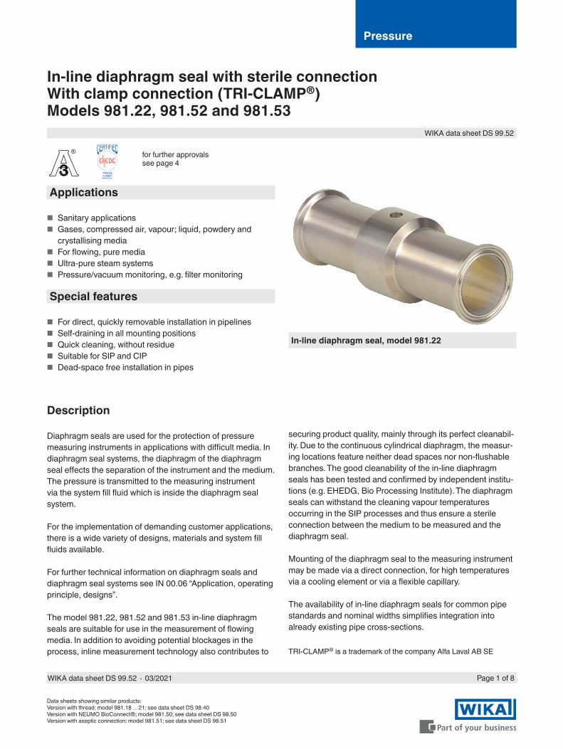
Installation example, model 981.22 directly mounted to model PSD-4 pressure switch
Pressure measuring instrument
Direct mounting
Diaphragm seal
Diaphragm, in-line diaphragm(welded to diaphragm seal)
Not included in delivery
ClampsSealings
Welding socket

WIKA data sheet DS 99.52 ∙ 03/2021 Page 3 of 8
Upper body of diaphragm seal Wetted parts (diaphragm) ¹⁾
Stainless steel 1.4435 (316L) Stainless steel 1.4435 (316L)Stainless steel 1.4435 (316L), electropolished ²⁾
Stainless steel 1.4435 (316L), electropolished ²⁾
Hastelloy C22 (2.4602) Hastelloy C22 (2.4602)Hastelloy C276 (2.4819) Hastelloy C276 (2.4819)
1) Marking of the parts with the material code guarantees 100 % material traceability2) Only in connection with a surface roughness of Ra ≤ 0.38 μm for the wetted parts
Further material combinations for special process temperatures on request.
Material combinations
Mounting variants for pressure gauges
For horizontal pipelinesVariant 1
■ Connection: Lower mount ■ Pointer shaft: Crosswise to flow
direction ■ Mounting: Direct mounting,
horizontal pipeline
Variant 2 ■ Connection: Lower mount ■ Pointer shaft: Parallel to flow
direction ■ Mounting: Direct mounting,
horizontal pipeline
Variant 3 ■ Connection: Lower back mount ■ Pointer shaft: Crosswise to flow
direction ■ Mounting: Direct mounting,
horizontal pipeline
Variant 4 ■ Connection: “At 12 o'clock” ■ Pointer shaft: Crosswise to flow
direction ■ Mounting: Direct mounting,
horizontal pipeline
For vertical pipelinesVariant 1
■ Connection: “At 3 o'clock” ■ Pointer shaft: Crosswise to flow
direction ■ Mounting: Direct mounting, vertical
pipeline
Variant 2 ■ Connection: “At 9 o'clock” ■ Pointer shaft: Crosswise to flow
direction ■ Mounting: Direct mounting, vertical
pipeline
Variant 3 ■ Connection: Lower back mount ■ Pointer shaft: Crosswise to flow
direction ■ Mounting: Direct mounting, vertical
pipeline
WIKA data sheet DS 99.52 ∙ 03/2021 Page 4 of 8
Approvals
Logo Description CountryEU declaration of conformityPressure equipment directive
European Union
EAC (option)Pressure equipment directive
Eurasian Economic Community
3-ASanitary Standard
USA
EHEDG 1)
Hygienic Equipment DesignEuropean Union
- CRNSafety (e.g. electr. safety, overpressure, ...)
Canada
- MTSCHS (option)Permission for commissioning
Kazakhstan
1) EHEDG conformity only in combination with ASEPTO-STAR k-flex upgrade, sealing from Kieselmann GmbH.
Certificates (option)
■ 2.2 test report per EN 10204- State-of-the-art manufacturing, material proof, indication accuracy for diaphragm seal systems- FDA conformity of the system fill fluid- 3-A conformity of the diaphragm seal, based on a third party verification- Manufacturer‘s declaration for food contact materials regarding regulation (EC) No. 1935/2004
■ 3.1 inspection certificate per EN 10204- Material proof, wetted metal partsIndication accuracy for diaphragm seal systems
■ Manufacturer‘s declaration for food contact materials regarding regulation (EC) No. 1935/2004 ■ Others on request
Approvals and certificates, see website
®
FEBRUARY 2021
TYPE ELCLASS I
WIKA data sheet DS 99.52 ∙ 03/2021 Page 5 of 8
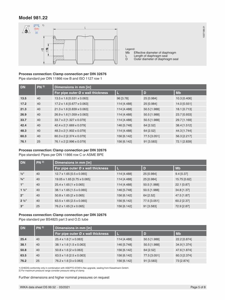
Model 981.22
1037
188.
01
Process connection: Clamp connection per DIN 32676Pipe standard per DIN 11866 row B and ISO 1127 row 1
DN PN 2) Dimensions in mm [in]For pipe outer Ø x wall thickness L D Mb
13.5 40 13.5 x 1.6 [0.531 x 0.063] 96 [3.78] 25 [0.984] 10.3 [0.406]17.2 40 17.2 x 1.6 [0.677 x 0.063] 114 [4.488] 25 [0.984] 14.0 [0.551]21.3 40 21.3 x 1.6 [0.839 x 0.063] 114 [4.488] 50.5 [1.988] 18.1 [0.713]26.9 40 26.9 x 1.6 [1.059 x 0.063] 114 [4.488] 50.5 [1.988] 23.7 [0.933]33.7 40 33.7 x 2 [1.327 x 0.079] 114 [4.488] 50.5 [1.988] 29.7 [1.169]42.4 40 42.4 x 2 [1.669 x 0.079] 146 [5.748] 64 [2.52] 38.4 [1.512]48.3 40 48.3 x 2 [1.902 x 0.079] 114 [4.488] 64 [2.52] 44.3 [1.744]60.3 40 60.3 x 2 [2.374 x 0.079] 156 [6.142] 77.5 [3.051] 56.3 [2.217]76.1 25 76.1 x 2 [2.996 x 0.079] 156 [6.142] 91 [3.583] 72.1 [2.839]
Process connection: Clamp connection per DIN 32676Pipe standard: Pipes per DIN 11866 row C or ASME BPE
DN PN 2) Dimensions in mm [in]For pipe outer Ø x wall thickness L D Mb
½" 40 12.7 x 1.65 [0.5 x 0.065] 114 [4.488] 25 [0.984] 9.4 [0.37]¾" 40 19.05 x 1.65 [0.75 x 0.065] 114 [4.488] 25 [0.984] 15.75 [0.62]1" 40 25.4 x 1.65 [1 x 0.065] 114 [4.488] 50.5 [1.988] 22.1 [0.87]1 ½" 40 38.1 x 1.65 [1.5 x 0.065] 146 [5.748] 50.5 [1.988] 34.8 [1.37]2" 40 50.8 x 1.65 [2 x 0.065] 156 [6.142] 64 [2.52] 47.5 [1.87]2 ½" 40 63.5 x 1.65 [2.5 x 0.065] 156 [6.142] 77.5 [3.051] 60.2 [2.37]3" 25 76.2 x 1.65 [3 x 0.065] 156 [6.142] 91 [3.583] 72.9 [2.87]
Process connection: Clamp connection per DIN 32676Pipe standard per BS4825 part 3 and O.D. tube
DN PN 2) Dimensions in mm [in]For pipe outer Ø x wall thickness L D Mb
25.4 40 25.4 x 1.6 [1 x 0.063] 114 [4.488] 50.5 [1.988] 22.2 [0.874]38.1 40 38.1 x 1.6 [1.5 x 0.063] 146 [5.748] 50.5 [1.988] 34.9 [1.374]50.8 40 50.8 x 1.6 [2 x 0.063] 156 [6.142] 64 [2.52] 47.6 [1.874]63.5 40 63.5 x 1.6 [2.5 x 0.063] 156 [6.142] 77.5 [3.051] 60.3 [2.374]76.2 25 76.2 x 1.6 [3 x 0.063] 156 [6.142] 91 [3.583] 73 [2.874]
1) EHEDG conformity only in combination with ASEPTO-STAR k-flex upgrade, sealing from Kieselmann GmbH.2) For maximum pressure range consider pressure rating of clamp.
Further dimensions and higher nominal pressures on request
®
FEBRUARY 2021
TYPE ELCLASS I
1)
Legend:Mb Effective diameter of diaphragmL Length of diaphragm sealD Outer diameter of diaphragm seal

WIKA data sheet DS 99.52 ∙ 03/2021 Page 6 of 8
®
FEBRUARY 2021
TYPE ELCLASS I
1)
Model 981.52
Process connection: Clamp connection per DIN 32676Pipe standard per DIN 11866 row A and DIN 11850 row 2
DN PN 2) Dimensions in mm [in]For pipe outer Ø x wall thickness L D Mb
25 40 29 x 1.5 [1.142 x 0.059] 114 [4.488] 50.5 [1.988] 26 [1.024]32 40 35 x 1.5 [1.378 x 0.059] 146 [5.748] 50.5 [1.988] 32 [1.26]40 40 41 x 1.5 [1.614 x 0.059] 146 [5.748] 50.5 [1.988] 38 [1.496]50 40 53 x 1.5 [2.087 x 0.059] 156 [6.142] 64 [2.52] 50 [1.969]65 25 70 x 2 [2.756 x 0.079] 156 [6.142] 91 [3.583] 66 [2.598]80 25 85 x 2 [3.346 x 0.079] 156 [6.142] 106 [4.173] 81 [3.189]100 25 104 x 2 [4.094 x 0.079] 156 [6.142] 119 [4.685] 100 [3.937]
1) EHEDG conformity only in combination with ASEPTO-STAR k-flex upgrade, sealing from Kieselmann GmbH.2) For maximum pressure range consider pressure rating of clamp.
Further dimensions and higher nominal pressures on request
1037
188.
01
Legend:Mb Effective diameter of diaphragmL Length of diaphragm sealD Outer diameter of diaphragm seal

WIKA data sheet DS 99.52 ∙ 03/2021 Page 7 of 8
®
FEBRUARY 2021
TYPE ELCLASS I
1)
Model 981.53
Process connection: Clamp connection per ISO 2852Pipe standard per ISO 2037 and BS 4825 part 1
DN PN 2) Dimensions in mm [in]For pipe outer Ø x wall thickness L D Mb
25 40 25 x 1.2 [0.984 x 0.047] 114 [4.488] 50.5 [1.988] 22.6 [0.89]33.7 40 33.7 x 1.2 [1.327 x 0.047] 146 [5.748] 50.5 [1.988] 31.3 [1.232]38 40 38 x 1.2 [1.496 x 0.047] 146 [5.748] 50.5 [1.988] 35.6 [1.402]40 40 40 x 1.2 [1.575 x 0.047] 146 [5.748] 64 [2.52] 37.6 [1.48]51 40 51 x 1.2 [2.008 x 0.047] 156 [6.142] 64 [2.52] 48.6 [1.912]63.5 40 63.5 x 1.6 [2.5 x 0.063] 156 [6.142] 77.5 [3.051] 60.3 [2.374]70 25 70 x 1.6 [2.756 x 0.063] 156 [6.142] 91 [3.583] 66.8 [2.63]76.1 25 76.1 x 1.6 [2.996 x 0.063] 156 [6.142] 91 [3.583] 72.9 [2.87]88.9 25 88.9 x 2 [3.5 x 0.079] 156 [6.142] 106 [4.173] 84.9 [3.343]101.6 25 101.6 x 2 [4 x 0.079] 156 [6.142] 119 [4.685] 97.6 [3.843]
1) EHEDG conformity only in combination with ASEPTO-STAR k-flex upgrade, sealing from Kieselmann GmbH.2) For maximum pressure range consider pressure rating of clamp.
Further dimensions and higher nominal pressures on request
1037
188.
01
Legend:Mb Effective diameter of diaphragmL Length of diaphragm sealD Outer diameter of diaphragm seal
WIKA data sheet DS 99.52 ∙ 03/2021 Page 8 of 8
© 11/2002 WIKA Alexander Wiegand SE & Co. KG, all rights reserved.The specifications given in this document represent the state of engineering at the time of publishing.We reserve the right to make modifications to the specifications and materials.
03/2
021
EN
WIKA Alexander Wiegand SE & Co. KGAlexander-Wiegand-Straße 3063911 Klingenberg/GermanyTel. +49 9372 132-0Fax +49 9372 [email protected]
Ordering informationDiaphragm seal:Diaphragm seal model / Process connection (type of process connection, pipe standard, pipe dimension) / Material (main body, diaphragm) / Surface roughness of wetted parts / Sealing / Zero point stabilisation (ZPS) / Connection to the measuring instrument / Level of cleanliness of wetted parts / Origin of wetted parts / Certificates
Diaphragm seal system:Diaphragm seal model / Process connection (type of process connection, pipe standard, pipe dimension) / Material (main body, diaphragm) / Surface roughness of wetted parts / Sealing / Zero point stabilisation (ZPS) / Pressure measuring instru-ment model (per data sheet) / Mounting (direct mounting horizontal/vertical, cooling element horizontal/vertical, capillary) / min. and max. process temperature / min. and max. ambient temperature / Vacuum service / System fill fluid / Certificates / Height difference / Level of cleanliness of wetted parts / Origin of wetted parts / Instrument mounting bracket