Embed Size (px)
Citation preview

Text and illustrations courtesy of Electronics Australia
If you're reading this, then chances arethat you're a TV and/or computer mon-
itor repair technician - who doesn't needto be told that horizontal output stagefaults cause more than their fair share ofheadaches! Operating at high voltages,frequencies and power levels, manycomponents in this part of the circuit arehighly stressed, and failures are not onlycommon but their cause is often hard toidentify.
The usual symptom of a major hori-zontal output stage fault is a seriousoverload of the DC power supply feedingthe primary winding of the line outputtransformer, or `LOPT' for short (calledthe `flyback' transformer or `FBT' inNorth America). This is often accompa-nied by a collector-to-emitter short cir-cuit in the horizontal output transistor or`HOT'.
(For consistency, we'll be referring tothe line output transformer as the `LOPT'throughout this article - North Americanreaders please mentally substitute `fly-back' for this term!)
Any of quite a few possible compo-nents could be the cause of such a failure,the more common being one of the high-speed rectifier diodes fed by the LOPT'ssecondary windings, including the diodestack(s) which produce the extra-high-
tension (EHT) supply of around 25 kilo-volts for the final anode circuit of thecathode ray tube. It's also possible theHOT has failed simply from old age oroverheating due to unevenly-applied/solidified heatsink compound.Another occasional culprit is an insula-tion breakdown in the deflection yoke'shorizontal winding.
However the failure which servicetechnicians dread is a shorted winding inthe LOPT itself. Unfortunately LOPTstend to be specifically designed for themake and model of the TV or monitorthey are used in, which can mean a lot ofhunting around for a replacement. Inaddition they are hardly ever cheap, andnot always physically easy to replace.
In short the LOPT is not a componentwhich is easy to test by substitution, anda service technician needs to be as cer-tain as possible that the LOPT really isdefective, before tracking down areplacement!
Identifying faults
Several techniques have been devel-oped over the years for identifying faultsin horizontal output stages, and testingLOPTs in particular for the presence ofshorted winding turns.
The components in the horizontal out-put transistor's collector circuit, includ-ing the LOPT's primary winding, deflec-tion yoke horizontal winding, and tuningcapacitors form a reasonably low loss(high Q) resonant circuit, especially atlow voltage levels.
Most testing techniques, including theone used in this design, are based on thefact that nearly all serious faults in the
������������
ACN 000 908 716
�� ��
In-circuit LOPT/FBTTester
K 7205
Please read Disclaimer carefully as wecan only guarantee parts and not thelabour content you provide.
Cat No.
Here’s the design for a low cost, easy to build and use battery operated ‘shorted turns’ tester forline-output or ‘flyback’ transformers, and other HF wound components like deflection yoke wind-ings and SMPS transformers. Tests have shown it capable of finding at least 80% of LOPT/FBTfaults, so it can save a lot of time and trouble. Small and rugged, it’s well worth a place in the toolk-it of anyone involved in servicing TV receivers, video monitors and computer power supplies.
WEBSITE: www.electronicsaustralia.com.auE-MAIL: [email protected]
PROJECT INFORMATION SUPPLIED BYELECTRONICS AUSTRALIA - August 1998 Issue
by Bob Parker
horizontal output stage will greatlyincrease the losses in the LOPT'sprimary circuit. That is, they lowerthe Q.
We chose the principle of `ring'testing as the basis for this instru-ment because it's easy to implementwith relatively simple circuitry andcommon components, and producespredictable results with no need forcalibration.
`Ring' testing gets its name fromthe fact that when a fast pulse isapplied to the primary winding ofthe LOPT, the total inductance andcapacitance in the circuit will produce anelectrical `ring' - a decaying AC voltagewhich can have a duration of a dozen ormore cycles before it reaches a lowvalue. It's the electrical equivalent of tap-ping an empty glass; in each case, anenergy impulse generates damped oscil-lations.
Waveform `A' in Fig.1 shows the HOTcollector voltage waveform in a typicalfault-free TV (a General ElectricTC63L1 in this case), in response to apulse from this tester. However if thelosses in the horizontal output circuit areincreased, the amplitude of the `ringing'waveform will decay much more quick-ly. Waveform `B' shows the effect of ashorted rectifier diode on one LOPT sec-ondary winding of the same TV, but notethat a shorted LOPT winding or severalother faults would have a similar effect.
A collector-emitter short in the HOTor a shorted tuning capacitor will resultin no ringing at all, indicating a reallymajor fault.
So to do an initial check of a horizon-tal output stage, with this tester, you firstmake sure the TV or monitor is de-ener-gised(!). Then you simply switch thetester on, connect the ground lead to the
chassis and the `HOT Collector' lead tothe horizontal output transistor's collec-tor. One LED will illuminate for each`ring' cycle above about 15% of the ini-tial pulse value, and in general if four ormore LEDs are glowing, the horizontaloutput stage is OK.
We'll talk more about using the testerlater, after the circuit description. For themoment though, it's worth mentioningthat because the tester uses a low-voltagetesting pulse, it is suitable for testingLOPTs `in circuit' - i.e., without havingto disconnect the yoke or other connec-tions.
Circuit description
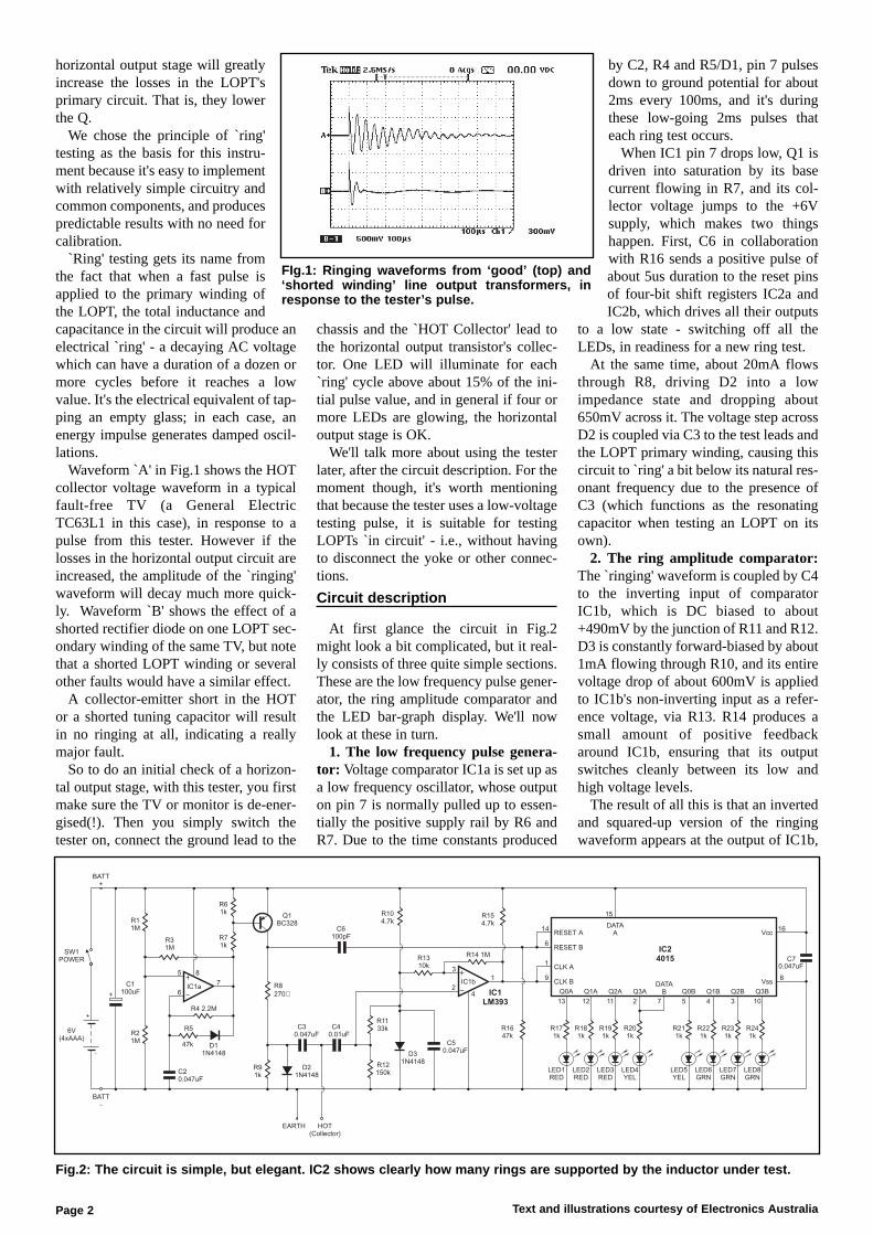
At first glance the circuit in Fig.2might look a bit complicated, but it real-ly consists of three quite simple sections.These are the low frequency pulse gener-ator, the ring amplitude comparator andthe LED bar-graph display. We'll nowlook at these in turn.
1. The low frequency pulse genera-tor: Voltage comparator IC1a is set up asa low frequency oscillator, whose outputon pin 7 is normally pulled up to essen-tially the positive supply rail by R6 andR7. Due to the time constants produced
by C2, R4 and R5/D1, pin 7 pulsesdown to ground potential for about2ms every 100ms, and it's duringthese low-going 2ms pulses thateach ring test occurs.
When IC1 pin 7 drops low, Q1 isdriven into saturation by its basecurrent flowing in R7, and its col-lector voltage jumps to the +6Vsupply, which makes two thingshappen. First, C6 in collaborationwith R16 sends a positive pulse ofabout 5us duration to the reset pinsof four-bit shift registers IC2a andIC2b, which drives all their outputs
to a low state - switching off all theLEDs, in readiness for a new ring test.
At the same time, about 20mA flowsthrough R8, driving D2 into a lowimpedance state and dropping about650mV across it. The voltage step acrossD2 is coupled via C3 to the test leads andthe LOPT primary winding, causing thiscircuit to `ring' a bit below its natural res-onant frequency due to the presence ofC3 (which functions as the resonatingcapacitor when testing an LOPT on itsown).
2. The ring amplitude comparator:The `ringing' waveform is coupled by C4to the inverting input of comparatorIC1b, which is DC biased to about+490mV by the junction of R11 and R12.D3 is constantly forward-biased by about1mA flowing through R10, and its entirevoltage drop of about 600mV is appliedto IC1b's non-inverting input as a refer-ence voltage, via R13. R14 produces asmall amount of positive feedbackaround IC1b, ensuring that its outputswitches cleanly between its low andhigh voltage levels.
The result of all this is that an invertedand squared-up version of the ringingwaveform appears at the output of IC1b,
Text and illustrations courtesy of Electronics AustraliaPage 2
LED4YEL
LED5YEL
LED1RED
R181k
R191k
R201k
R211k
R221k
R231k
R241k
R171k
R14 1M
D31N4148
R12150k
+
-
6V(4xAAA)
SW1POWER
C1100uF
BATT+
BATT-
R21M
R11M
R31M
6
5
7
8
IC1a
R4 2.2M
IC1
LM393
IC2
4015
R5
D11N4148
C20.047uF
47k
D21N4148
R91k
C30.047uF
C40.01uF
R71k
R61k
Q1BC328
C6100pF
R1133k
R8
270�
C50.047uF
R1310k
3
2
1
4
IC1b
R104.7k
R154.7k
R1647k
HOT(Collector)
EARTH
LED2RED
LED3RED
LED6GRN
LED7GRN
LED8GRN
13 12 11 2 7 5 4 3 10
15
14
6
1
9
16
8
C70.047uF
RESET A
RESET B
CLK A
CLK B
DATAA
Q0A Q1A Q2A Q3ADATA
B Q0B Q1B Q2B Q3B
Vss
Vcc
+
Fig.2: The circuit is simple, but elegant. IC2 shows clearly how many rings are supported by the inductor under test.
FIg.1: Ringing waveforms from ‘good’ (top) and‘shorted winding’ line output transformers, inresponse to the tester’s pulse.

until the ringing amplitude has decayeddown to about 15% of its initial value.This square wave is connected straight tothe clock inputs of shift registers IC2aand IC2b.
3. The LED bargraph display: IC2consists of a pair of identical four-bitserial-in/parallel-out shift registers, con-nected to form a single eight-bit unit,with each output driving one LED in the`bargraph' display via resistors R17 toR24. The serial data input of the firststage (pin 15) is permanently connectedto the positive supply, or logic 1.
One measurement
For the first 5us after the commence-ment of a new 2ms measuring pulse,both shift registers are reset to zeroes onall outputs, as described earlier. At thesame time the initial positive pulseapplied to the LOPT drives IC1b's out-
put, connected to both shift registers'clock inputs, to a low (logic 0) level -unless the test leads are shorted.
If the LOPT primary circuit is OK, itwill ring during the next several hundredmicroseconds. For each ring above about15% of its initial value, it will cause ahigh-going pulse to be applied to theshift register clock inputs, resulting inthe logic 1 on IC2 pin 15 being movedone shift register stage further along. Itdoesn't matter if the LOPT rings morethan eight times - all LEDs will stillremain illuminated.
So the overall result is that one LEDilluminates for each LOPT ring cycleabove 15% of the initial level, and thiscondition remains until the start of thenext 2ms measuring pulse. Phew!
Usage & limitations
In order to assess the usefulness of thisdesign, we gave several prototypeLOPT/FBT testers to technician friendsto evaluate for many months, then askedfor their comments and thoughts on howto put the tester to best use.
The first response is from Larry Sabo,an experienced monitor technician inOttawa, Canada who also suggested thefront panel layout:
One of the first things I do to check out
a monitor is connect the tester betweenthe HOT collector and ground. If no oronly a few LEDs light, I check the HOT,damper diodes and tuning caps forshorts using a DMM. If these are OK, Icheck for an open fusible resistor in thecircuit feeding B+ to the LOPT, and forshorts/leakage in diodes on the LOPTsecondaries. I also check the bypasscapacitor on the DC supply to the LOPTprimary for excessive ESR.
If these check OK, I ring the horizontalyoke with its connector unplugged. It willnormally ring seven times on its own. Ifthe yoke rings OK, I unsolder all but theLOPT primary winding and ground pins,and ring the primary. If the primary stillrings low with everything else discon-nected, the LOPT is probably defective.
Most LOPTs on their own will ring 8+times, but some ring only four or five,even when they are perfectly normal. Soit is prudent to confirm the diagnosis byringing an identical known-good LOPT,if at all possible.
Sometimes an LOPT is defective, butstill rings normally with the tester, e.g.due to leakage or arcing that only occursat full operating voltage. The problemwill sometimes be manifest by heavyloading of the B+ supply, spurious ring-ing and/or reduced voltages on the HOT
Text and illustrations courtesy of Electronics Australia Page 3
Fig.3: Use this PCB overlay and the facing photo as a guide in assembling thetester.
Resistors(All 5% 0.25W carbon) R1,2,3,14 1MR4 2.2MR5,16 47kR6,7,9,R17-24 1kR8 270 ohmsR10,15 4.7kR11 33kR12 150kR13 10k
CapacitorsC1 100uF 16/25VW
RB electrolyticC2,3,5,7 0.047uF MKTC4 0.01uF MKTC6 100pF disc ceramic
SemiconductorsD1,2,3 1N914 / 1N4148 silicon
diodeIC1 LM393 dual comparatorIC2 4015 / MC14015 / CD4015
dual 4-bit shift registerLED1,2,3 Rectangular red LEDLED4,5 Rectangular yellow LEDLED6,7,8 Rectangular green LEDQ1 BC328 / 2N5819 PNP
silicon transistor
MiscellaneousPCB, ZA1137 51 x 76mm; small (UB3) plastic case, 130 x 68 x 41mm (DSE H-2853); front panel; battery holder for 4 x AAA cells; battery snap ; power switch, push on/off; one DIP8 IC socket, one DIP16; 4 x tapped spacers; screws, nuts and washers (see Screw size and allocation guide); 1 x red, 1 x black 4mm banana sockets; test leads with 4mm banana plugs; double-sided adhesive tape; wire, PCB pins, solder and instruc-tions.
Parts List

collector, or excessively high EHT result-ing in HV shut-down.
Because this tester uses impulses ofonly 650mV to minimize the forwardbiasing of semiconductors, such defectswill not be reflected in the ring count.Under these circumstances, I check formeasurable leakage resistance betweenthe EHT cap and the other LOPT pins. Itshould be unmeasurable, otherwise theLOPT is defective.
If I have gone through the above testsand have these symptoms and a normalring count on the tester, the diagnosiscan usually be confirmed only by substi-tuting a known-good identical LOPT, orby testing with a chopper similar to theone described in Sam Goldwasser'sElectronics Repair FAQ, located on theInternet at http://pacwest.net/byron13/sam/flytest.htm.
Something else I do when testing aLOPT is to supply it with a reduced B+to enable scoping the HOT and measur-ing EHT (in situations where the monitorgoes into HV shutdown). To reduce theB+, I use two light bulbs in series, oneend to B+ supply, centre-tap to LOPT B+connection, other end to ground. Onebulb is 60 watts, the other is 100, so I canreverse the end leads and increase ordecrease the B+ value used in testing.
At the outset, when I have power sup-ply cycling but have confirmed there areno shorts from HOT-C to ground, I sub-stitute a dummy load (60W bulb) for theLOPT where the B+ enters, to see if thepower supply works with the LOPT outof the equation.
Overall, the LOPT tester can identifyabout 80% of LOPT failures. When try-ing to solve a puzzle, if someone offersinformation that is right 80% of the time,it's a lot better than having to guess100% of the time, especially if the ante isthe price of a LOPT and wasted, valu-able time.
Michael Caplan does general electron-ic servicing in Ottawa, and added the fol-lowing useful points in relation to TVs:
It's pretty straightforward to use, withthe usual precautions of ensuring thatthe under-test unit power is off and anycaps are discharged.
When testing an LOPT in circuit, itmight be necessary to disconnect some ofthe LOPT terminals, and/or yoke plugsthat could load it down and upset thereadings. The tester will often not detectbad HV diodes in integrated split-diodeLOPT units, nor shorts/arcing that isvoltage dependent - but then no otherpassive tester does either.
I have found it useful for checking TVdeflection yokes, both horizontal andvertical. A good yoke lights at least fiveand typically the full eight LEDs.However, many yokes have built-in par-allel or series damping resistors, and
these must be temporarily disconnected.Otherwise the reading will be low, eventhough the winding itself is fine.
The tester can be used for checkinghigh-Q transformers such as those usedin SMPS's. However, my experience hasshown that it will not provide more thana two or three LED indication for goodTV horizontal drive transformers. It canbe used for these, however - to indicateshorts (no LEDs lit). On the other handthe ESR Meter (Dick Smith catalog num-ber K-7204) can do much the same withthese low resistance transformers.
Wayne Scicluna services TVs inSydney, and is the technician who talkedme into developing the tester in the firstplace. Here are his hints:
If you've already checked for the moreobvious leaky and shorted semiconduc-tors and capacitors etc., and are still get-ting a low reading on the tester, there aresome other traps to avoid.
You need to get a good connection withthe test leads, because contact resistancecan cause a low reading. The sameapplies to defective solder joints in thehorizontal output stage, especially on theLOPT itself and HOT. In fact connectingthe tester with clip leads, flexing theboard and wiggling components is agood way to show up bad solder joints inthis area.
Body conductivity can also cause alower than normal reading if you'retouching the test leads and your skin isdamp. Low readings can also be causedby having the test leads reversed, i.e.,connecting 'HOT Collector' to chassis,and by faults in an external voltagetripler.
How to build it
Before soldering anything to the print-ed circuit board, hold it up to a brightlight and examine the copper side care-fully for fine track breaks and especiallywhiskers or bridges - particularly wheretracks pass close to component solderpads.
Referring to the board overlay in Fig.3,begin installing the components, startingwith the resistors and diodes and work-ing your way up to the tall ones includingthe four PCB pins for `GND', `HOT' and`+6V' terminal connections- but leaving
Text and illustrations courtesy of Electronics AustraliaPage 4
Value 4 Band (1%) 5 Band (1%)
270R Red-Vio-Brn-Brn Red-Vio-Blk-Blk-Brn1K Brn-Blk-Red-Brn Brn-Blk-Blk-Brn-Brn4.7K Yel-Vio-Red-Brn Yel-Vio-Blk-Brn-Brn10K Brn-Blk-Org-Brn Brn-Blk-Blk-Red-Brn33K Org-Org-Org-Brn Org-Org-Blk-Red-Brn47K Yel-Vio-Org-Brn Yel-Vio-Blk-Red-Brn150K Brn-Grn-Yel-Brn Brn-Grn-Blk-Org-Brn1M Brn-Blk-Grn-Brn Brn-Blk-Blk-Yel-Brn2.2M Red-Red-Grn-Brn Red-Red-Blk-Yel-Brn
Resistor Colour Codes
Printed Circuit Board to Spacers4 x Screw M3 x 6mm (zinc plated)
Front Panel to Spacers4 x Screw Countersunk M3 x 6mm (Blk)
Front Panel To Case4 x Screw Countersunk No4 x 6mm (Blk)
Screw Size and AllocationGuide
Value IEC Code EIA Code
100pF 100p 101K0.01uF 10n 103K0.047uF 47n 473K
Capacitor Codes
The assembled PCB, which supportsvirtually all of the circuitry.

the LEDs off the board for now. Takecare with the orientation of the polarisedcomponents, including the IC sockets.
With everything but the LEDs installedon the PCB, once again illuminate itfrom the top, and check for and correctany solder bridges or other problems.
Now turn your attention to the frontpanel, mounting the banana sockets andthe power switch in their respectiveholes.
Attach the tapped spacers to the cor-ners of the board using plain 3mmscrews, and solder long component leadoffcuts to the `GND', `HOT Collector'and `+' solder pads, followed by the bat-tery snap's black wire to the `-' pad.Then, without soldering them, poke theleads of all the LEDs through theirrespective holes in the board. Make surethe coloured LEDs are in their correctplaces, and that all the (long) anode and(short) cathode leads are correctly orient-ed as shown in Fig.3.
Using black countersunk 3mm screws,attach the front panel to the board assem-bly and place the whole thing face-downon a soft flat surface. Manoeuvre all ofthe LEDs into their cutouts in the frontpanel, and push each LED down slightlyto ensure its face is level with the front ofthe panel. In the unlikely event that aLED won't fit, use a small file or similarto remove the excess powder coatinginside the hole.
Now solder all the LEDs into place,then connect the test lead sockets and theclosest terminal of the power switch totheir respective wires from the board,and finally the red battery snap wire tothe free switch contact (Ref. to Fig.4.
wiring diagram).Snip off the battery holder's PCB
mounting pins, then install four `AAA'cells into it. Connect the battery snap tothe terminals, and switch the unit on. Ifeverything's OK then the bottom red (`1')LED will illuminate, and shorting thetest leads will cause it to go off.
An effective way to test the unit is to
connect the test leads to the primarywinding of a known good LOPT out ofcircuit, which should bring all eightLEDs on. Then thread a loop of solderaround the ferrite core of the LOPT(simulating a single shorted turn), andthe LED count should drop to 1-3 as theloop is closed.
If everything's OK, use double-sided
Text and illustrations courtesy of Electronics Australia Page 5
Fig.4: Shows how the battery snap (positive lead) is wired through the switch tothe printed circuit board. Note, as the component overlay shown is viewed fromthe copper side of the PCB, wiring terminations for the Power and HotCollector/GND should be made to the PCB pins on the component side of theboard.

ACN 000 908 716CNR Lane Cove & Waterloo Roads
North Ryde NSW 2113PH: (02) (lnt 612) 9937 3200 Fax: (02) 9888 3631
Text and illustrations courtesy of Electronics Australia Dick Smith Electronics © ZA8738-2
adhesive tape to stick the battery holderinto the bottom of the case, with the cellsaligned in a `north-south' direction foreasiest access. All that remains to be
done now is to screw the front panel intoplace and try out your tester on someLOPTs and their associated circuitry.
Finally, our sincere thanks to Larry
Sabo, Michael Caplan and WayneScicluna for their assistance in complet-ing this project. We couldn't have done itwithout you!
Case
Battery holder
PCB
Front panel
M3 x 6mm
Countersunk
screw
Double-sided
tape
Case pillar
No4 x 6mm
Countersunk
S/T screw
Banana
socket
M3 x 6mm
Pan head
screw
Spacer
Fig.5: Shows how the PCB with LEDs is mounted to the frontpanel using 19mm hex tapped spacers. The battery holder isfixed to the bottom of the case by two pieces of double-sizedtape.
Winding a Test CoilIn order for constructors to test the unit once assembled we have provided details
and parts to construct a simple transformer coil which enables the circuit to ring all'8' LEDs.
Please refer to the following for coil details.1.Using the balun core provided, wind around 45 turns (tightly wound) through
the two centre holes as shown in the accompanied photo.2.Once completed trim lead length to approximately 50mm and clean the enamel
from each lead end so that a positive connection can be made.3.Now test the coil, the unit should display and ring all '8' LEDs. By simply feed-
ing through an additional winding and shorting the ends will reduce the rings toeither 1 or 2 LEDs giving a good indication that the unit is working correctly.
Parts Supplied1 x Balun core (R 5440)1 x Enamel copper wire (30B&S or 0.25mm dia x 2 metres)
Assembly Notes

Testing of Flyback (LOPT) Transformers Contents:
l Chapter 1) About the Author & Copyright l Chapter 2) Introduction l 2.1) Scope of this document l Chapter 3) Flyback (LOPT) Transformers l 3.1) What does the flyback (LOPT) transformer do? l 3.2) How is a flyback transformer different than a regular transformer? l 3.3) The origin of the term, 'flyback' l 3.4) A little history l 3.5) Why is the deflection and high voltage combined? l 3.6) Flyback construction l 3.7) Why you don't want to fabricate your own flyback or rebuild a bad one l 3.8) Why do flyback (LOPT) transformers fail? l 3.9) How do flyback transformers fail? l 3.10) Basic testing l 3.11) The process of elimination l 3.12) Advanced testing l 3.13) Method 1 l 3.14) Method 2 l 3.15) Identifying the high voltage return on a flyback l 3.16) Method 2 testing procedure l 3.17) Flyback testing equipment l 3.18) Quickie in-circuit flyback tests l 3.19) Why do all flyback (LOPT) transformers seem to be unique? l 3.20) Typical flyback schematic l 3.21) Replacement flyback transformers l 3.22) OEM flyback transformers
[Document Version: 1.45] [Last Updated: 05/25/1998]
Chapter 1) About the Author & Copyright Testing of Flyback (LOPT) Transformers
Author: Samuel M. Goldwasser
Corrections/suggestions: | [email protected]
Copyright (c) 1994, 1995, 1996, 1997, 1998 All Rights Reserved
Reproduction of this document in whole or in part is permitted if both of the following conditions are satisfied:
1. This notice is included in its entirety at the beginning. 2. There is no charge except to cover the costs of copying.
[Feedback Form]
Page 1 of 18Testing of Flyback

Chapter 2) Introduction
Safety ------ WARNING: Read, understand, and follow the recommendations in the document: "Safety Guidelines for High Voltage and/or Line Powered Equipment" before attempting any TV or monitor repairs.
2.1) Scope of this document
When problems develop in the horizontal deflection/high voltage subsystems of TVs or monitors (or even modern oscilloscopes and other CRT displays), the flyback transformer (or line output transformer for those on the other side of the Lake) is often a suspected cause. This is due in part to the fact that it is usually the most expensive and hard to find replacement and because flybacks are often less well understood than other more common components. This document addresses the operation and testing of flyback (LOPT) transformers: What they are, how they fail, why they fail, and how to test them. For more information on horizontal deflection systems, see the document: "TV and Monitor Deflection Systems".
Chapter 3) Flyback (LOPT) Transformers
3.1) What does the flyback (LOPT) transformer do?
The typical flyback or Line OutPut Transformer (LOPT) consists of two parts: 1. A special transformer which in conjunction with the horizontal output transistor/deflection circuits boosts the B+ (120 V typical for a TV) of the low voltage power supply to the 20 to 30 KV for the CRT as well as provide various secondary lower voltages for other circuits.
Page 2 of 18Testing of Flyback

A HV rectifier turns the high voltage pulses into DC and the CRT capacitance smooths it. The HV may be developed from a single winding with many many turns of wire or a lower voltage winding and a diode-capacitor voltage multiplier. The various secondary voltages power the logic, tuner, video signal, vertical deflection circuits, and CRT filaments. In fact, with many TV designs, the only power not derived from the flyback is for the keep-alive circuitry needed to maintain channel memory and provide startup drive to the horizontal deflection/high voltage system. 2. A voltage divider that provides the focus and screen supplies. The pots are in this divider network - and these things fail resulting poor focus, uncontrolled brightness, or fluctuating focus and/or brightness. A total short could also result in failure of other components like the horizontal output transistor. The focus and screen are generally the top and bottom knobs, respectively. In some TVs, the focus and screen divider and/or controls are external to the flyback and susceptible to dust and problems particularly on damp days.
3.2) How is a flyback transformer different than a regular transformer?
While the following is not always strictly true for TV and monitor flyback transformers, it is a nice overview: (From: Sivasankar Chander ([email protected])). The main difference between a flyback transformer and a regular transformer is that a flyback transformer is designed to store energy in its magnetic circuit, i.e., it functions like a pure inductor, whereas a regular transformer is designed to transfer energy from its primary to secondary and to minimize stored energy. Secondly, a flyback transformer in its simplest form has current flowing either in its primary, or in its secondary (but not both at the same time). (This is more complicated in practice because of finite turn-off times for transistors and diodes, need for snubber circuits, etc). Thirdly, the reluctance of the magnetic circuit of a flyback transformer is usually much higher than that of a regular transformer. This is because of a carefully calculated air-gap for storing energy (it's an inductor). Fourthly, the voltages applied to a flyback transformer on the primary side are almost always rectangular (pulsed) whereas regular transformers usually have sinusoidal voltages applied to them. Fifthly, the currents flowing through either side of a flyback transformer are either increasing or decreasing linear sawtooths, whereas a regular transformer usually has sinusoidal currents. Finally, due to the properties of core materials, flyback transformers are most conveniently operated in the range from 10^3 to 10^6 Hz, whereas regular transformers have a much wider range, from a few Hz to 10^12 Hz. I may have succeeded in confusing you beyond redemption, so the best recourse for you would be to read any introductory textbook on switching power supplies for a more comprehensive picture.
Page 3 of 18Testing of Flyback

3.3) The origin of the term, 'flyback'
In the U.S. (possibly all of North America), the transformer that generates the high voltage in a TV, monitor, or other CRT based equipment, is called the 'flyback' or 'flyback transformer'. Most everywhere else in the world, it is either LOPT (Line OutPut Transformer) or simply LOT. The term 'flyback' probably originated because the high voltage pulse that charges the CRT capacitance is generated by the collapse of the magnetic field in the core of the transformer during the short retrace period - when the electron beam in the CRT 'flies back' to the start of a new scan line. The flux in the core changes slowly during scan and is abruptly switched in polarity by the HOT turning off and damper diode turning on during this flyback or retrace period. Many off-line switchmode power supplies and DC-DC converters are also of the 'flyback' type with energy transferred to their output circuits mainly during the same time in the cycle - but there is no CRT involved and their high frequency transformers are not generally called flyback transformers. LOPT and LOT derive from the fact that it is the line scan circuit that is involved and the transformer is in the output stage. I still think flyback is much more quaint! :-). Of course, others have their own definition: (From: Sam Riner ([email protected])). When I was about 12 I touched the wire coming from the FBT on the picture tube, this was a BIG floor model TV, and I flew about five feet backwards. I know this isn't the real history for the name but for many years I believed it was.
3.4) A little history
So, how far back does the use of a flyback based high voltage go? (From: Henry van Cleef ([email protected])). A flyback HV supply was a feature of the 1946 RCA 630 and GE 801 sets. They used either an 807 or 6BG6 horizontal output tube, 6W4 damper, 1B3 rectifier. The prewar TV's (yes, TV's were made and for sale before the NTSC standard was approved in 1941) generally used a 60 Hz. transformer and 2X2 similar to circuits used in RCA and Dumont oscilloscopes of the 1930's. Zworykin/Morton "Television" (Wiley, 1940) has schematics and a project home-brew TV set using an 81 tube for the HV off a standard power transformer. Of course, to follow your way around this book, you have to know vacuum tube theory and a lot of physics reasonably well, but it is an historical gold mine.
Page 4 of 18Testing of Flyback

(From: Brad Thompson ([email protected])). Some of the early TV sets used an RF oscillator to generate the high voltage for electrostatic-deflection CRTs: a typical tube lineup might include a 6V6 oscillator and 1B3 (or 1X2) rectifier.
3.5) Why is the deflection and high voltage combined?
One of the main reasons that TVs and many monitors are designed with horizontal deflection driven flybacks is simply economics - it provides a cheap way to get the high voltage and many or most of the other voltages for the set with minimal hardware. (High quality computer monitors sometimes use a separate high voltage supply so that the horizontal deflection is then used just for deflection to reduce interactions between changing scan rates and the HV.) A side benefit is that if the horizontal deflection dies, the power supply voltage goe with it and prevents the CRT phosphors from burning do to undeflected high intensity beam. The use of the horizontal frequency rather than the AC line frequency of 50 or 60 Hz allows the power supply components to be small and light compared to a line operated power transformer and filter capacitors.
3.6) Flyback construction
While details can vary somewhat, all flybacks consist of a set of windings on a gapped ferrite core. High voltage diodes and resistive dividers (often with adjustment pots) for focus and screen (G2) may also be present. A typical flyback includes the following components: * Drive winding - for a line powered TV, there will be perhaps a hundred turns of medium gauge (e.g., AWG #26) wire. This is what is connected in series with the B+ to the horizontal output transistor in a TV or monitor. * High voltage winding - several thousand turns. This winding may be split into several series sections with a high voltage rectifier for each or could be a single winding. An alternative is provide a lower voltage winding and use a voltage multiplier (diode-capacitor ladder) to boost this to that required by the CRT. Very fine wire (e.g., AWG #40) will be used for the high voltage winding. The high voltage lead to the CRT is fed from the highest voltage output of the rectifier or multiplier. Some TV and monitor designs use a physically separate (external - not part of the flyback transformer) voltage multiplier. In this case, the flyback high voltage winding will generate 6 to 10 KVAC and the multiplier will boost this typically 3X or 4X to 20 to 30 KVDC. The focus and screen (G2) network will generally be part of the multiplier in this case. * Resistive divider network for focus and screen (G2). This will probably be fed from only one of the series connected windings (if used). Often, there are adjustments for focus and screen right on the flyback. The outputs from this divider may be connected to pins in the base of the flyback or
Page 5 of 18Testing of Flyback

have their own separate leads which connect to the CRT socket/board. * Auxiliary windings - anywhere from a couple of turns (for the CRT filament) to several hundred turns (for a boost source). These supply various voltages for the typical TV or monitor - CRT filament, logic power, analog power, boost source (where the flyback does not include its own screen supply), etc. The gauge of these windings will depend on the current requirements of each output. They are connected to solder pins at the base of the flyback. * Ferrite core - consisting of two C shaped pieces clamped together with either a spring arrangement or studs and nuts. There will be a gap of a fraction of a mm provided by a set of spacers between the two C sections. Most modern flybacks have all the windings on the same leg of the core. The drive winding and auxiliary windings will be wound and separately insulated under the high voltage winding. The high voltage winding will consist of many layers which have insulating material (i.e., mylar) between them. The other components will be mounted in a separate part of the assembly and the entire unit is then potted in an Epoxy type filler. Part of the core is generally accessible - often one entire leg. A flyback is not an ordinary transformer. The ferrite core contains a gap. Energy is stored in the magnetic field of the core during scan as the current is ramping up. Energy is also coupled to certain secondary outputs during scan. However, energy for the high voltage (HV) is coupled to the its secondary windings almost entirely when the primary current is shut off at the end of the scan (probably the source of the name flyback because it is during the retrace of the electron beam). Which type of coupling is in effect depends on the direction of the rectifiers on the secondary side of the flyback: _ _ \/ _/\_ B+ ------+ +----|>|-----+---o +V1 B+ ------+ +----|>|-----+---o +HV o )|:|( o Scan | o )|:|( Flyback | )|:|( Rectifier _|_ )|:|( Rectifier _|_ )|:|( --- )|:|( --- )|:|( | )|:|( | _/\_ )|:|( | _/\_ )|:|( o | HOT ------+ +------------+--+ HOT ------+ +------------+--+ _|_ _|_ - - Here, V1 is just a typical example of an auxiliary supply derived from a scan rectifier and HV is the best known example of the use of a flyback rectifier. Note that the ratio of the number of turns for each winding *cannot* be used to calculate expected output voltages since the rate of collapse of the magnetic field (determined by the design of the horizontal output circuit) affects this. The gap is critical to the proper operation and is usually determined by some plastic spacers. CAUTION: mark each one and replace them in exactly the same position if you disassemble the core for any reason.
3.7) Why you don't want to fabricate your own flyback or rebuild a bad one
Page 6 of 18Testing of Flyback

Disassemble a flyback and you will understand why I don't recommend this unless the entire future of the explored *and* unexplored universe depends on the effort! You need specialized equipment to just wind the high voltage coil. This isn't something you can do by hand in your basement and the only problem isn't the several thousand turns of nearly invisible wire used in a typical flyback. To sustain the high voltages without arcing and to minimize the interwinding capacitance, the high voltage winding is constructed as many individual layers - perhaps 50 layers in all - of 50 turns each using super fine wire (#40 typical - thinner than a human hair). Each layer must be wound perfectly flat with all wires side-by-side and then individually insulated with mylar tape. Just breathing on such wire will practically break it let alone wrapping several thousand turns in perfect order! The other parts: drive and low voltage windings, focus and screen divider network, and high voltage rectifiers must be assembled with the high voltage winding and CRT leads and then the entire affair is potted in Epoxy. Forget it - you have better things to do than spend a week on a transformer!
3.8) Why do flyback (LOPT) transformers fail?
While flyback transformers can on occasion be blown due to a failure elsewhere in the TV or monitor's power supply or deflection circuits, in most cases, they simply expire on their own. Why? Flybacks are wound with many layers of really really fine wire with really really thin insulation. This entire assembly is potted with an Epoxy resin which is poured in and allowed to cure. In some ways, these are just short circuits waiting to happen. Flybacks get hot during use and this leads to deterioration of the insulation. Any imperfections, nicks, or scratches in the insulation or trapped air bubbles and impurities in the Epoxy fill material contribute to failure. Temperature cycles and manufacturing defects result in fine cracks in the Epoxy potting material reducing the insulation breakdown particularly in the area of the high voltage windings, rectifiers, and focus/screen divider network. They also physically vibrate to some extent. A whole bunch of other factors are also no doubt important. Once a breakdown - sparking or arcing - develops, it is usually terminal. It is amazing they last as long as they do with the stresses they are under.
3.9) How do flyback transformers fail?
Flybacks fail in several ways:
Page 7 of 18Testing of Flyback

1. Overheating leading to cracks in the plastic and external arcing. If there is no major damage to the windings, repair may be possible. However, arcing from the windings punctures their very thin insulation so that shorted windings may already have developed. Even if the windings are currently in good condition, long term reliability of any such repairs is questionable. Nonetheless, it doesn't hurt to try cleaning and coating with multiple layers of high voltage sealer, corona dope, or even plastic electrical tape (preferably as a temporary repair though I have gotten away with leaving this in place permanently). If possible, moving the point to which the flyback is arcing further away (i.e., a piece of metal or another wire) would also help. (The following from: Tom Riggs ([email protected])) For sealing flyback transformers, I have found that silicone sealer has worked very well. I used the clear variety, though others will probably work as well. I have heard of burn through with corona dope. (Author's note: make sure you allow ample time for the silicone sealer to setup completely - or else it will breakdown instantly - at least 24 hours. Also, some types (those that smell like vineger - acetic acid - as they cure may result in corroded wiring in the long term). 2. Cracked or otherwise damaged core will effect the flyback characteristics to the point where it may not work correctly or even blow the horizontal output transistor. If the core can be reconstructed so that no gaps are present and clamped and/or glued in place, it should be possible to perform testing without undue risk of circuit damage but consider a replacement flyback as a long term solution. 3. Internal shorts in the FOCUS/SCREEN divider network, if present. One sign of this may be arcover of the FOCUS or SCREEN spark gaps on the PCB on the neck of the CRT. 4. Internal short circuits in the windings. 5. Open windings. More than one of these may apply in any given case. As noted, temporary repair, at least, is sometimes possible for failures (1) and (2). For failures (3) to (5) replacement is usually the only alternative.
3.10) Basic testing
First, perform a careful visual inspection with power off. Look for cracks, bulging or melted plastic, and discoloration, Look for bad solder connections at the pins of the flyback as well. If the TV or monitor can be powered safely, check for arcing or corona around the flyback and in its vicinity, Next, perform ohmmeter tests for obvious short circuits between windings, much reduced winding resistances, and open windings. Don't neglect to check between the CRT HV connector (suction cup) and the pins on the base. This should measure infinity. For the low voltage windings, service manuals may provide the expected DC resistance (Sams' Photofact, for example). Sometimes, this will change enough to be detected - if you have an ohmmeter with a low enough scale. These are usually a fraction of an ohm. It is difficult or impossible to measure the DC resistance of the HV winding since the rectifiers are usually built in. The value is not published either.
Page 8 of 18Testing of Flyback
Caution: make sure you have the TV or monitor unplugged and confirm that the main filter capacitor is discharged before touching anything as the flyback is usually connected to this point, perhaps directly! If you are going to remove or touch the CRT HV, focus, or screen wires, discharge the HV first using a well insulated high value resistor (e.g., several M ohms, 5 W) to the CRT ground strap (NOT signal ground). Measurements that are much less than the published values likely indicate a partially shorted winding. However, a difference of 10% may not be at all significant. Higher than normal readings might simply indicate that a design change was made you. Yes, I know, hard to believe they would not have informed you of this! For example, various versions of the flyback used in the Apple MAC Plus - 157-0042A,B,C - are functionally similar but have minor variations in winding parameters. It is not known what effects this would have but they are interchangeable at least for testing. Of course, any continuity between separate windings is definitely a fault. Partially short circuited windings (perhaps, just a couple of turns) and sometimes shorts in the focus/screen divider will drastically lower the Q and increase the load the flyback puts on its driving source with no outputs connected. It is these types of failures, not detectable by simple ohmmeter tests or visual inspection, which the techniques described in the sections under "Advanced testing" address. While less common, I have seen shorts between the CRT HV connector and the low voltage windings on the base of the flyback. This implies a breakdown of the Epoxy potting material probably due to thermally induced microcracks or poor quality manufacturing. Once a small arc develops, it rapidly carbonizes the material around it further reducing the resistance. These rarely heal themselves and thus show up as obviously low resistance readings using an ohmmeter. It is an easy test and can be performed without removing the flyback. Discharge the CRT HV (though this will probably be dead) and just remove the connector from the CRT. It is also possible that various types of flyback faults can damage other circuitry (beyond taking out the horizontal output transistor and its associated parts). For example, a sudden short between the CRT HV connector and a low voltage winding or a short between two low voltage windings could conceivably blow solid state components powered from the flyback. This damage will generally not be apparent until the flyback is replaced. Therefore, if shorts are detected in the flyback, it may be worth testing some of the components in the vicinity though such tests will likely not prove conclusive.
3.11) The process of elimination
Before attempting the more advanced tests suggested below, there may be ways of being more certain that your flyback is the problem component. The following assumes that running the TV or monitor with the suspect flyback results in an excessive load on the low voltage (B+) power supply blowing a fuse (or attempting to blow a fuse - excessively bright series light bulb). The B+ likely drops from its normal 65 VDC to 140 VDC or more (depending on the actual TV or monitor and mode) to some low value like 25 VDC when measured on the low voltage power supply side of the flyback drive winding. (Measuring at the HOT can result in all sorts of weird readings due to the pulse nature of the waveform and is not recommended - especially when everything is working properly - 1,500 V pulses!). * Disconnect all the secondary loads from the suspect flyback including the
Page 9 of 18Testing of Flyback

CRT. Connect only the drive (B+ and HOT). Power up the TV or monitor (preferably with a series light bulb or on a Variac. If the B+ now climbs to a more normal value, a problem with the HV (CRT short) or one of the secondary loads is indicated. Connect each of these up one a time (or test individual components) to localize the fault. The flyback is likely good. * Remove the suspect flyback and connect just the HOT and B+ to the drive winding of a known good flyback for a similar size TV or similar type of monitor (as appropriate). It may be close enough to keep the drive circuitry happy. Power up the TV or monitor (preferably with a series light bulb or on a Variac. If the B+ now climbs to a more normal value, a problem with the original flyback is indicated. However, more thorough testing may be desirable to be absolutely certain. If you do this regularly, keeping a selection of 'flyback simulators' - just the drive windings and cores may be desirable.
3.12) Advanced testing
Also see the section: "Flyback testing equipment". There are several ways of testing flybacks (assuming you do not actually have special test equipment for this purpose). Here are two possibilities. The first is easier if you have a scope but the second is more fun.
3.13) Method 1
The following technique works for flybacks, chopper transformers, motors, mains transformers, deflection yoke windings, VCR video and other magnetic heads, and other transformers, coils, or inductors. (Portions from: Gabe ([email protected])). This is called a 'ring test' and is the method often used by commercial flyback (or other coil/transformer) testers. The theory is that a faulty flyback (which cannot be found by simple resistance measurements) will have shorted turns in one of the coils. In such a case, the 'Q' of the transformer is greatly reduced. If excited by an impulse, a faulty transformer will resonate with a highly damped oscillation while a good one will decay gradually. 1) Connect a high quality capacitor across one winding of the suspect device. Hope for a resonant frequency of a few kHz. You may need to select the capacitor value for best results. I have found that a capacitor in the
Page 10 of 18Testing of Flyback

.001 uF to 1 uF (non-polarized) will usually be satisfactory. Note that it doesn't matter whether the excitation is applied to the shorted winding or any other one. However, you should avoid trying to connect the generator to one of the very small windings like those for the CRT filament which may only have 2 or 3 turns. 2) Apply a pulse waveform to the parallel resonant circuit. In 1960, most scopes had a 'sync out' on the timebase that provided a few 10s of volts at enough current for this. A circuit in "Television" magazine a couple of years ago used a BU508, a 12 V power supply, and a small oscillator built from a 4011 chip. A function generator or a 555 timer based circuit will also make a satisfactory stimulous. Also see the section: "Flyback testing equipment 3) Look at the waveform across the resonant circuit with a 'scope. A good unit will give a nicely decaying oscillation, of at least a few cycles, possibly 10's of cycles. If there is a shorted turn *anywhere* in the device, the oscillations will be seriously damped, and you'd be lucky to see 2 complete cycles. Experience and/or comparison with a known good device will tell you what to expect. Scope _ o Pulse or _| |_ | Device under Test function o---------------------+-----------+ +--- Generator | )|:|( High Quality _|_ )|:|( All other Non-polarized --- )|:| +--- windings Capacitor | )|:| +--- left open | )|:|( Ground o---------------------+-----------+ +--- (From: James Elliott ([email protected])). I tried the Q evaluation method using the 100 volt CAL voltage pulse from a Tektronix scope. It worked best when I used a series 200 pF capacitor. I got maybe 100 pulses before it decayed to zero. If I shorted two of the primary pins, the decaying pulse train went to zero almost immediately. So it works! I thought of another method. The Q of a resonant circuit is equal to the center frequency divided by the half power bandwidth. I applied an audio generator through a 22k resistor, found the peak frequency, then went off that frequency to .707 of that amplitude. Double this would be the bandwidth. I got Q's of 26 and 16 for two I tried. (Editor's note: This appears to be a valid approach.)
3.14) Method 2
The circuit below excites the flyback in much the same way as in normal operation. The only caution is that this tester probably does not put enough stress on the flyback to find an intermittent that fails only under full operating conditions. However, most flyback failures are solid - once a short develops, there is a meltdown of sorts and it is there to stay. You will require a 12 V power source of at least 2 or 3 amps capacity (regulation is not important - I just use a simple transformer, rectifier, filter capacitor type of power supply). The circuit is shown below. None of the component values are critical. +12 Q1 +----------------+ |:|
Page 11 of 18Testing of Flyback

o | ) |:| | B |/ C ) |:| <-- Flyback Under Test --> | +------| 2N3055 ) |:| | | |\ E 5T ) |:| +------|>|----------o +HV | | | ) |:| ( HV Diode(s), | | -_- ) |:| ( usually built in. | | ) |:| +-----+ ( +--|-------------------------+ |:|( )|:|( | | Q2 _-_ ) |:|( 10T )|:|( | | | ) |:|( each )|:|( | | B |/ E 5T ) |:|( _ )|:|( | | +---| 2N3055 ) |:|( _|_ )|:|( | | | |\ C ) |:| +-- --+ ( | | | | ) |:| Switch ( | | | +----------------+ |:| ( | | | |:| ( | | -----------------------+ |:| +------------------o -HV | | 2T ) |:| | | +-----------+ |:| (Numerous other windings not shown.) | | | 2T ) |:| | +-------------------------+ |:| Note: |:| denotes ferrite core. | | | R1 | R2 +--------/\/\/\--+--/\/\/\---+ 110 27 _|_ 2W 5W - Note: if the circuit does not start oscillating at about 5 volts or less, interchange the two feedback connections to the transistor bases. The tester is just a chopper feeding the salvaged core from an old flyback (I removed the inductance control spacers for this core). The drive (5T+5T) and feedback (2T+2T) coils can be wound from hookup wire (#14-#20) and well insulated with plastic electrical tape. Connect the center taps directly to the coils - do not bring out a loop of wire. Make sure all the turns of each coil are wound in the same direction. Wind the feedback coil directly on top of the drive coil. The secondary of this core is a 10 turn well insulated coil similar to the other two wound on the opposite side of the ferrite core. You will need to remove the suspect flyback from the TV or monitor. Another 10 turn coil is wound on the suspect flyback core anywhere it will fit. Connect one end of this coil to one end of the 10 turn coil on your old flyback core. Use a wire nut or twist together securely. Provide an easy way of connecting the other ends momentarily - a push button comes in handy. Make sure you locate the HV return lead on the flyback and use that as the return for the arc. Otherwise, you may puncture the insulation when the high voltage finds it own path to ground.
3.15) Identifying the high voltage return on a flyback
It is essential that this be correctly connected or else the high voltage *will* find a suitable path to ground - and it may not do the other circuitry any good! There are several approaches that can be taken - possibly in combination: * Process of elimination - the HV return will often be an isolated pin on the flyback not connected to anything else. Therefore, if you test between all combinations of pins on the flyback (removed from the circuit board)
Page 12 of 18Testing of Flyback
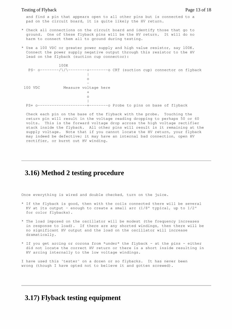
and find a pin that appears open to all other pins but is connected to a pad on the circuit board, it is quite likely the HV return. * Check all connections on the circuit board and identify those that go to ground. One of these flyback pins will be the HV return. It will do no harm to connect them all to ground during testing. * Use a 100 VDC or greater power supply and high value resistor, say 100K. Connect the power supply negative output through this resistor to the HV lead on the flyback (suction cup connector): 100K PS- o--------/\/\--------+--------o CRT (suction cup) connector on flyback | o - 100 VDC Measure voltage here + o | PS+ o---------------------+--------o Probe to pins on base of flyback Check each pin on the base of the flyback with the probe. Touching the return pin will result in the voltage reading dropping to perhaps 50 or 60 volts. This is the forward voltage drop across the high voltage rectifier stack inside the flyback. All other pins will result in it remaining at the supply voltage. Note that if you cannot locate the HV return, your flyback may indeed be defective; it may have an internal bad connection, open HV rectifier, or burnt out HV winding.
3.16) Method 2 testing procedure
Once everything is wired and double checked, turn on the juice. * If the flyback is good, then with the coils connected there will be several KV at its output - enough to create a small arc (1/8" typical, up to 1/2" for color flybacks). * The load imposed on the oscillator will be modest (the frequency increases in response to load). If there are any shorted windings, then there will be no significant HV output and the load on the oscillator will increase dramatically. * If you get arcing or corona from *under* the flyback - at the pins - either did not locate the correct HV return or there is a short inside resulting in HV arcing internally to the low voltage windings. I have used this 'tester' on a dozen or so flybacks. It has never been wrong (though I have opted not to believe it and gotten screwed).
3.17) Flyback testing equipment
Page 13 of 18Testing of Flyback

Sencore and others sell test equipment that includes the 'ring test' or similar capabilities built in. For the professional, these are well worth the expense. However, the hobbyist could probably purchase lifetime TV replacements for the cost of once of these fancy gadgets. Various electronics magazines have published construction articles for various types of simplified versions of these devices. Here is a pointer to one such article: (Portions from: Tony Duell ([email protected])). The February 1998 issue of 'Television' magazine, has a simple circuit for an LOPT (Line Output Transformer - flyback transformer) tester. It uses a TBA920 chip as an oscillator, driving a BUT11AF which supplies the primary of the LOPT. The voltage developed across this winding (the back EMF when the transistor is turned off) is shown on a DMM. There's also a 'scope point to look at the waveform produced. However, there are a few errata in the article: 1. The supply voltage is 12 V as mentioned in the text, not 2 V as shown on the schematic. 2. The peak amplitude given in fig. 3 of 8 V should be after the divider network, not at the transformer itself. 3. There is a capacitor shown from pin 13 (decoupling) which almost certainly should be a bypass to ground, not to the collector of the drive transistor.
3.18) Quickie in-circuit flyback tests
Note: Larry has 'beta tested' Bob Parker's (of ESR meter fame) soon to be introduced flyback tester. (From: Larry Sabo ([email protected])). Checking out flybacks can be frustrating and very time consuming without a good tester. Now, it just takes me a second to check for ringing on the HOT collector. No ringing? Check the HOT with a DVM for shorts. No shorts? Unsolder all flyback legs except the primary winding and check for rings again. No rings? Shorted turns in the flyback! Bob's estimate that 20% of faulty flybacks have internal leakage or arcing, or bad HV diodes, seems about right. And an LC102 (tester) won't catch these either :-). I've found that about half of these show up with a low resistance measurement between the EHT cap and ground. Sometimes scoping the output at the EHT cap shows unrectified ringing but stray capacitance probably accounts for that. Other times, it's clearly rectified, so go figure. As a last resort, I resort to Sam's chopper to wrestle the hold-outs to the ground, but it takes a bit of time to remove the flyback and put 10-15 turns around the core. The ringer has also helped me isolate a defective yoke, which explained why things wouldn't ring. Anyway, I think Bob's tester is a great little unit and am glad I have had the opportunity to test it--and keep the prototype! :-)
Page 14 of 18Testing of Flyback
3.19) Why do all flyback (LOPT) transformers seem to be unique?
(Most of these comments also apply to SMPS high frequency transformers.) Of all the components in a monitor or TV, the flyback is very likely to be a unique part. This is not so much due to the high voltage winding and/or HV multipler but rather related to its usual function as the source of multiple secondary power supply voltages used by various tuner, deflection, video, and audio subsystems. In addition, inductance, capacitance, pin configuration, and HV, focus, and screen outputs must be compatible. ECG and similar companies do have a line of generic FBTs and should have a catalog/cross reference for these similar to the one for semiconductors. See the section: "Replacement flyback transformers". However, FBTs are where the designers of TVs and monitors can be really creative. After all, specifying the flyback windings gives them complete freedom to pick the number and types of secondary voltages! Your chances of picking up something off the street so-to-speak and expecting it to fit anything you have ever owned - or ever will own - isn't great. (From: an engineer at a TV manufacturer). We have one guy whose mission in life is doing exactly that... (and specifing HOT's too). Besides specifying auxiliary secondaries you can also specify an overturn on the primary (for deflection coils which would otherwise require a >1500 V HOT) and influence the tuning of the EHT secondary, to determine the EHT internal impedance. And finally you might specify a built-in EHT capacitor or bleeder resistor and various types of clicked-on potmeter modules (perhaps with a second focus voltage for DAF).
3.20) Typical flyback schematic
This diagram shows a typical flyback that might be found in a direct view color television or computer monitor. Resistances are included for illustrative purposes only and may be quite different on your flyback! The high voltage section on the right may actually be constructed as a voltage multiplier rather than a single winding with multiple HV diodes. The rectifiers or multiplier, and/or focus/screen divider may be external to the flyback transformer in some models. Flyback transformers used in black-and-white TVs and monochrome computer monitors do not have a focus and screen divider network. Older ones do not include a high voltage rectifier either - it is external. The ferrite core of a flyback transformer is constructed with a precision gap usually formed by some plastic spacers or pieces of tape. Don't lose them if you need to disassemble the core. The ferrite core is also
Page 15 of 18Testing of Flyback

relatively fragile, so take care. The focus and screen divider network uses potentiometers and resistors (not shown) with values in the 10s to 100s of M ohms so they may not register at all on your multimeter. The high voltage rectifiers (CR1 to CR3 on this diagram) are composed of many silicon diodes in series and will read open on a typical VOM or DMM. Note that there is no standardization to the color code. However, the fat wire to the CRT is most often red but could also be black. Of course, you cannot miss it with the suction cup-like insulator at the CRT anode end. The focus and/or screen connections may also be to pins rather than flying leads. |:| +--|>|-----------o HV to CRT _ 1 |:|( CR1 (25 to 30 KV, | B+ o-------------+ |:|( suction cup on Drive | )|:|( fat red wire) winding < )|:| +-------+ | 1.32 )|:| | | 2 )|:| +--|>|--+ |_ HOT o-------------+ |:|( CR2 _ 3 |:|( | 50 o-------------+ |:|( | )|:| +-------+ | .11 4 )|:| | | 35 o-------------+ |:| +--|>|--+ Various | )|:|( CR3 | auxiliary < .28 )|:|( / windings | 5 )|:|( \<-------o Focus | 16 o-------------+ |:|( / (3 to 10 KV, | )|:|( \ orange wire) | .12 6 )|:|( | |_ 0 o----------+--+ |:|( 9 | _ | 7 |:| +--+ / | H1 o----------)--+ |:| | \<-------o Screen CRT Heater < .08 | 8 )|:| | / (200 to 800 V, |_ H2 o----------+--+ |:| | \ brown wire) | |:| | | | |:| +----|--------o To CRT DAG | | ground +----------------+
3.21) Replacement flyback transformers
Unfortunately, you cannot walk into Radio Shack and expect to locate a flyback for your TV or monitor. It is unlikely the carrots at the counter will even know what a flyback is or recognize one if it hit them over the head (wherever that would be on a carrot). They will probably attempt to sell you a 6.3 V power transformer :-). Fortunately, there are other options: * Original manufacturer - most reliable source but most expensive. Older models may not be available. This may be the only option for many TVs and monitors - particularly expensive or less popular models. * Electronics distributors - a number of places including MCM Electronics, Dalbani, Premium Parts, and Computer Component Source (See the document: "Notes on the Troubleshooting and Repair of Computer and Video Monitors" for contact info) sell replacement flybacks. Many of these are actually original parts and are designated as such. However, there may be no way
Page 16 of 18Testing of Flyback

of knowing and you may end up with something that isn't quite compatible (see below). Thus, unless the catalog listing says 'original part', these may be no better than the sources below. Here is one apperently just for flybacks: - Component Technologies, 1-888-FLYBACK or 1-800-878-0540. email: [email protected]. and one that is mostly for flybacks: - CRC Components, 1-800-822-1272. some others: - Data Display Ltd, Canadian sub of CCS, 1-800-561-9903. - EDI (Electro Dynamics, Inc.) NY, 1-800-426-6423. - Global Semiconductors, 1-800-668-8776, Toronto, http://globalsemi.com. * Generic replacements - these are sometimes available. ECG, NTE, ASTI, HR Diemen, for example, offer a line of replacement flybacks. Some of these sites include a cross reference to their replacement based on TV or monitor model and/or the part or house number on the flyback: - NTE (NTE Electronics, Inc), http://www.nteinc.com/ - ECG (Philips), http://www.ecgproducts.com/ - HR (HR Diemen), http://www.hrdiemen.es/ - ASTI (ASTI Mgnetics) However, these may be of lower quality or not be quite compatible with your original. In an effort to minimize the number of distinct flyback models, some corners may be cut and one-size-fits-many may be the rule resulting in all sorts of problems. Here are a couple of possibilities: - The number of turns on one or more windings may not quite match your original meaning there will be lower or higher voltages from certain outputs and/or drive conditions (current, resonance) may be affected. - There may even be extra or missing connections - pins on the bottom or flying leads. It is essential to determine what must be done to make the flyback work in your equipment *before* applying power. Extra connections may need to be grounded or connected to some other points in the circuit. If this is not done, operation may not be correct or other parts may blow as current from these unconnected pins finds its own way to ground. - The flyback may simply be defective due to bad quality control, part number confusion, or mismarking. Internal circuitry such as the focus and screen(G2) divider could be improperly wired, configured for a different model, or omitted entirely. Such defects can be very tough to identify. Thus, marginal or erratic behavior might result from generic replacements greatly complicating your troubleshooting since without careful measurements there is no way of knowing whether the problem is due to the new flyback or a fault that still exists elsewhere. Here is one example of such a situation: (From: Michael Caplan ([email protected])). "The FBTs that I tried (three samples in two generic brands available here in Canada) all seem to be missing the required internal voltage divider. This was confirmed by comparison with a new oem Sony part. The OEM part exhibits the proper resistance measurement. It is through this resistance that the Hold Down voltage is derived. "No resistance = no Hold Down voltage", as far as I can see." Disclaimer: I do not know how likely it is to have problems such as these.
Page 17 of 18Testing of Flyback

In most cases, I would expect the replacement to drop right in and perform perfectly. However, I have heard of occasionally difficulties. I do not know which, if any, of the companies listed above sell such incompatible devices. However, it would be worth checking before buying if possible.
3.22) OEM flyback transformers
Elim Technology has an on-line resource with their OEM flyback transformers (and other components including deflection yokes). These include complete specifications and pinouts so this site may be useful to get an idea of typical flyback characteristics: * http://www.elim.com/ (Elim Technology) * http://www.elim.com/product/dy.html (Flyback specifications)
Written by Samuel M. Goldwasser. | [mailto]. The most recent version is available on the WWW server http://www.repairfaq.org/ [Copyright] [Disclaimer]
[Feedback Form]
Page 18 of 18Testing of Flyback