Embed Size (px)
Citation preview

i.MX51 EVK Hardware User’s Guide
Document Number: - 924 - 76363
Rev. 1.7
10/2010
Freescale Semiconductor i.MX51 EVK Hardware User’s Guide, Rev 1.7 II
How to Reach Us: Home Page: www.freescale.com E-mail: [email protected] USA/Europe or Locations Not Listed: Freescale Semiconductor Technical Information Center, CH370 1300 N. Alma School Road Chandler, Arizona 85224 +1-800-521-6274 or +1-480-768-2130 [email protected] Europe, Middle East, and Africa: Freescale Halbleiter Deutschland GmbH Technical Information Center Schatzbogen 7 81829 Muenchen, Germany +44 1296 380 456 (English) +46 8 52200080 (English) +49 89 92103 559 (German) +33 1 69 35 48 48 (French) [email protected] Japan: Freescale Semiconductor Japan Ltd. Headquarters ARCO Tower 15F 1-8-1, Shimo-Meguro, Meguro-ku, Tokyo 153-0064, Japan 0120 191014 or +81 3 5437 9125 [email protected] Asia/Pacific: Freescale Semiconductor Hong Kong Ltd. Technical Information Center 2 Dai King Street Tai Po Industrial Estate Tai Po, N.T., Hong Kong +800 2666 8080 [email protected] For Literature Requests Only: Freescale Semiconductor Literature Distribution Center P.O. Box 5405 Denver, Colorado 80217 1-800-441-2447 or 303-675-2140 Fax: 303-675-2150 [email protected]
Information in this document is provided solely to enable system and software implementers to use Freescale Semiconductor products. There are no express or implied copyright licenses granted hereunder to design or fabricate any integrated circuits or integrated circuits based on the information in this document. Freescale Semiconductor reserves the right to make changes without further notice to any products herein. Freescale Semiconductor makes no warranty, representation or guarantee regarding the suitability of its products for any particular purpose, nor does Freescale Semiconductor assume any liability arising out of the application or use of any product or circuit, and specifically disclaims any and all liability, including without limitation consequential or incidental damages. “Typical” parameters that may be provided in Freescale Semiconductor data sheets and/or specifications can and do vary in different applications and actual performance may vary over time. All operating parameters, including “Typicals”, must be validated for each customer application by customer’s technical experts. Freescale Semiconductor does not convey any license under its patent rights nor the rights of others. Freescale Semiconductor products are not designed, intended, or authorized for use as components in systems intended for surgical implant into the body, or other applications intended to support or sustain life, or for any other application in which the failure of the Freescale Semiconductor product could create a situation where personal injury or death may occur. Should Buyer purchase or use Freescale Semiconductor products for any such unintended or unauthorized application, Buyer shall indemnify and hold Freescale Semiconductor and its officers, employees, subsidiaries, affiliates, and distributors harmless against all claims, costs, damages, and expenses, and reasonable attorney fees arising out of, directly or indirectly, any claim of personal injury or death associated with such unintended or unauthorized use, even if such claim alleges that Freescale Semiconductor was negligent regarding the design or manufacture of the part. Learn More: For more information about Freescale products, please visit www.freescale.com. Freescale™ and the Freescale logo are trademarks of Freescale Semiconductor, Inc. All other product or service names are the property of their respective owners. © Freescale Semiconductor, Inc. 2010. All rights reserved.
Freescale Semiconductor i.MX51 EVK Hardware User´s Guide, Rev 1.7 III
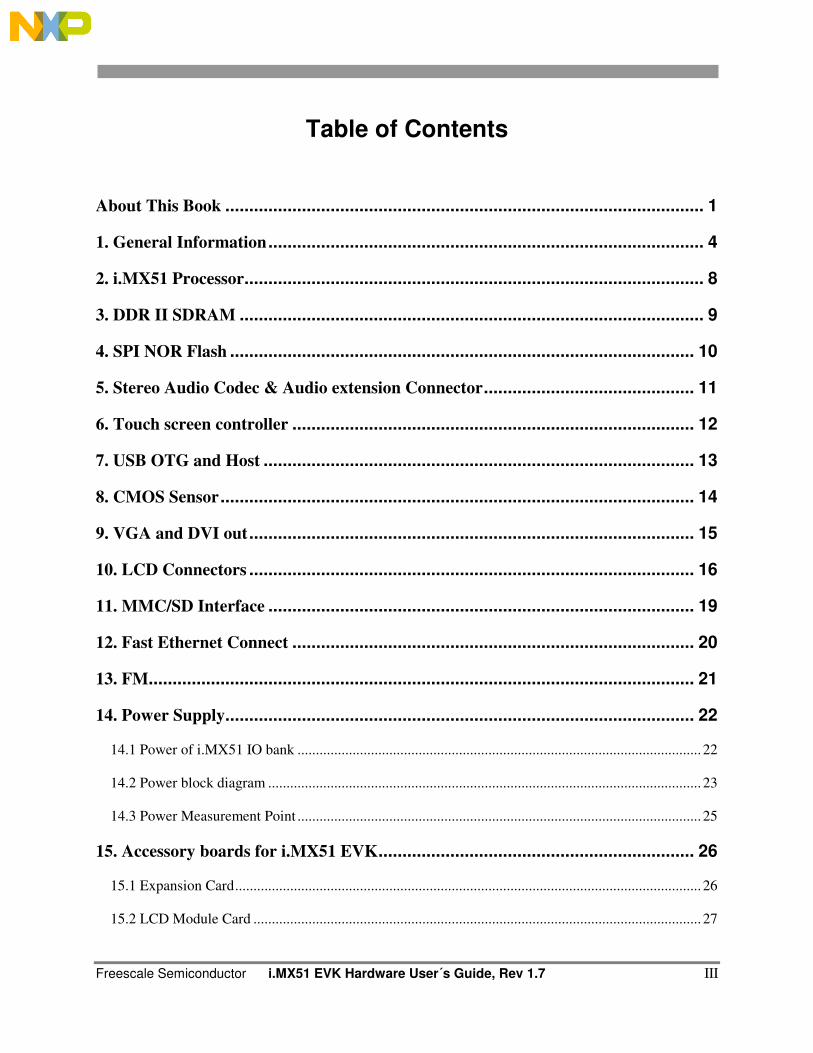
Table of Contents
About This Book .................................................................................................... 1
1. General Information ........................................................................................... 4
2. i.MX51 Processor ................................................................................................ 8
3. DDR II SDRAM ................................................................................................. 9
4. SPI NOR Flash ................................................................................................. 10
5. Stereo Audio Codec & Audio extension Connector ............................................ 11
6. Touch screen controller .................................................................................... 12
7. USB OTG and Host .......................................................................................... 13
8. CMOS Sensor ................................................................................................... 14
9. VGA and DVI out ............................................................................................. 15
10. LCD Connectors ............................................................................................. 16
11. MMC/SD Interface ......................................................................................... 19
12. Fast Ethernet Connect .................................................................................... 20
13. FM.................................................................................................................. 21
14. Power Supply.................................................................................................. 22
14.1 Power of i.MX51 IO bank .............................................................................................................. 22
14.2 Power block diagram ...................................................................................................................... 23
14.3 Power Measurement Point .............................................................................................................. 25
15. Accessory boards for i.MX51 EVK .................................................................. 26
15.1 Expansion Card ............................................................................................................................... 26
15.2 LCD Module Card .......................................................................................................................... 27
Freescale Semiconductor i.MX51 EVK Hardware User’s Guide, Rev 1.7 IV
15. Boot mode setting for i.MX51 EVK ................................................................. 29
16. Know Issues .................................................................................................... 30
Freescale Semiconductor i.MX51 EVK Hardware User’s Guide, Rev 1.7 1
About This Book
This manual explains how to connect and operate the i.MX51 EVK System.
Audience
This document is intended for software, hardware, and system engineers who are planning to use the
product and want to understand more about the product
Revision History
2009.08 Ver1.0
2009.09 Ver1.6
2009.10 Ver1.7
Reference Documents
1. MCIMX51EVKJ Product Preview (Rev. 0) , Freescale Semiconductor, 2009.01
2. Atlas AP Lite MC13892 Reference Manual (Rev 2.0), Freescale Semiconductor, 2008.11
3. MC34713 Datasheet(Rev 4.0), Freescale Semiconductor, 2007.05
4. SGTL5000 Datasheet, SigmaTel, 2007.04
5. EDE1116AEBG, 1Gb DDR2 SDRAM Specification, Elpida, 2008.01
6. SD Memory Card Specifications, SD Group, 2001.04.
Acronyms and Abbreviations
The following acronyms and abbreviations are used in this manual. This list does not include signal,
register, and software mnemonics.
ATA Hard drive interface spec
CD Compact Disk
CMOS Complementary Metal Oxide Semiconductor
CPLD Custom Programmed Logic Devices

Freescale Semiconductor i.MX51 EVK Hardware User’s Guide, Rev 1.7 2
CPU Central Processing Unit
CSI Camera Sensor Imaging
CSPI Serial Peripheral Interface
DCE Data Communications Equipment
DDR Double Data Rate
DIP Dual In-line Package
DMA Direct Memory Access
DTE Data Terminal Equipment
DUART Dual Universal Asynchronous Receiver/Transmitter
EEPROM Electrically Erasable Programmable Read Only Memory
EPROM Erasable Programmable Read Only Memory
FIR Infra Red
GPIO General Purpose Input/Output
GPO General Purpose Output
I2C Inter-Integrated Circuit
ICE In-Circuit Emulator
I/O Input/Output
IrDA Infrared Data Association
ISA Instrumentation, System, and Automation Society
JTAG Joint Test Access Group
LAN Local Area Network
LCD Liquid Crystal Display
LED Light Emitting Diode
MB Megabyte
MCU Microcontroller Unit
MMC Multi-media Card
Freescale Semiconductor i.MX51 EVK Hardware User´s Guide, Rev 1.7 3
MCP Multi-chip product
MS Memory Stick
NVRAM Non-volatile Random Access Memory
OTG On the Go
PC Personal Computer
PCMCIA Personal Computer Memory Card International Association
PCB Printed Circuit Board
PHY Physical interface
POR Power on Reset
PSRAM Pseudo Random Access Memory
PWM Pulse Width Modulation
QVGA Graphics Adapter
RAM Random Access Memory
SD SanDisk (Smart Media)
SDRAM Synchronous Dynamic Random Access Memory
SI System International (international system of units and measures)
SIMM Single In-Line Memory Module
SPST Single Pole Single Throw
SSI2 Synchronous Serial Interface
TFT Thin Film Transistor
UART Universal Asynchronous Receiver/Transmitter
USB Universal Serial Bus
Freescale Semiconductor i.MX51 EVK Hardware User’s Guide, Rev 1.7 4
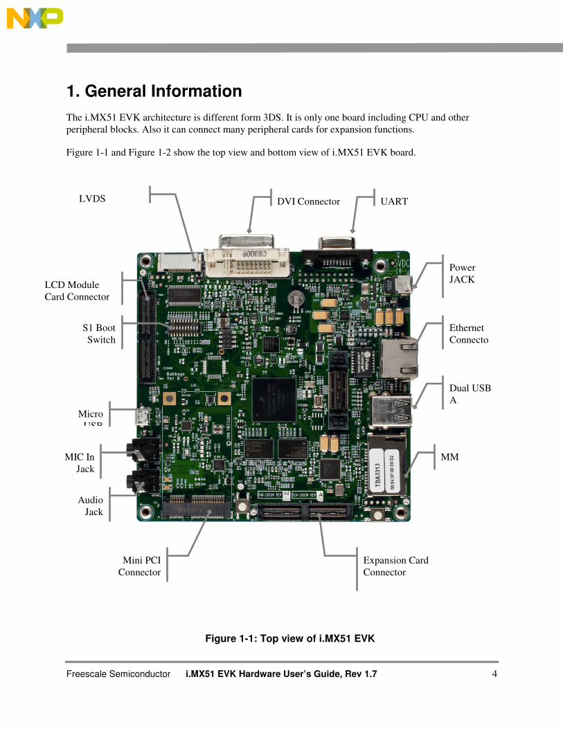
1. General Information
The i.MX51 EVK architecture is different form 3DS. It is only one board including CPU and other
peripheral blocks. Also it can connect many peripheral cards for expansion functions.
Figure 1-1 and Figure 1-2 show the top view and bottom view of i.MX51 EVK board.
Figure 1-1: Top view of i.MX51 EVK
Audio
Jack
Power
JACK
Mini PCI
Connector
Expansion Card
Connector
LVDS DVI Connector UART
Ethernet
Connecto
r
Dual USB
A
MM MIC In
Jack
Micro
USB
LCD Module
Card Connector
S1 Boot
Switch
Freescale Semiconductor i.MX51 EVK Hardware User´s Guide, Rev 1.7 5
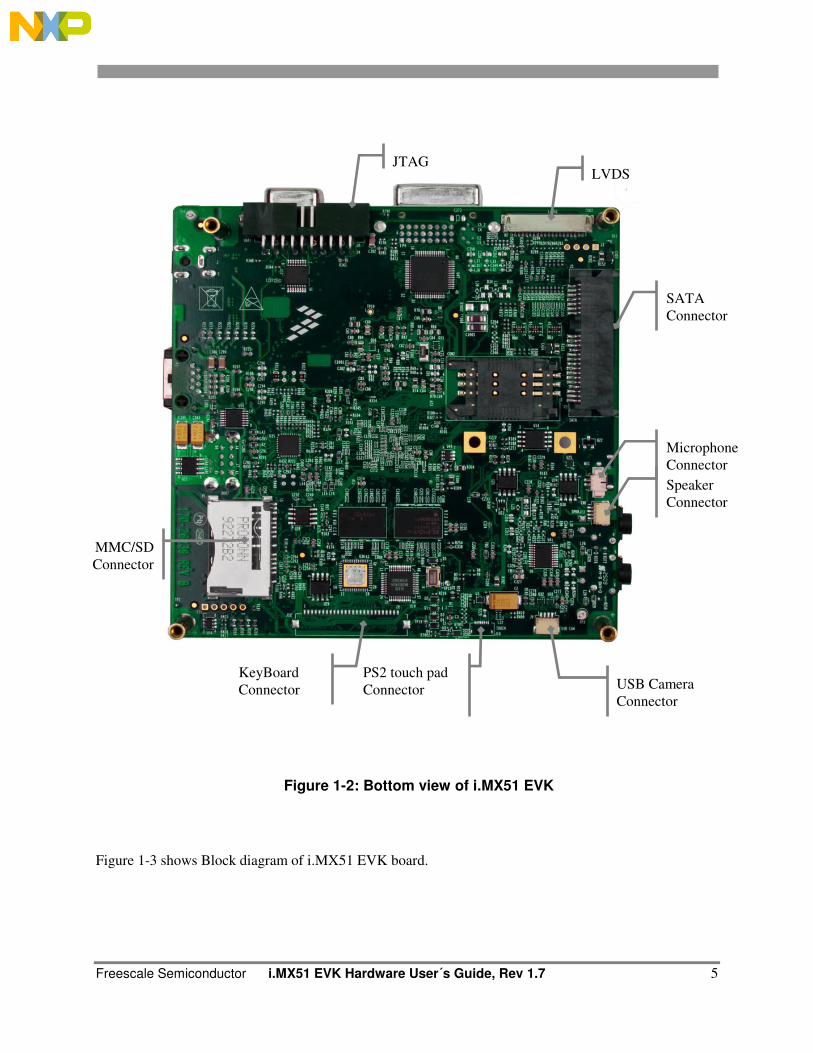
JTAG LVDS
SATA
Connector
Microphone
Connector
Speaker
Connector
MMC/SD
Connector
USB Camera
Connector
KeyBoard
Connector
PS2 touch pad
Connector
Figure 1-2: Bottom view of i.MX51 EVK
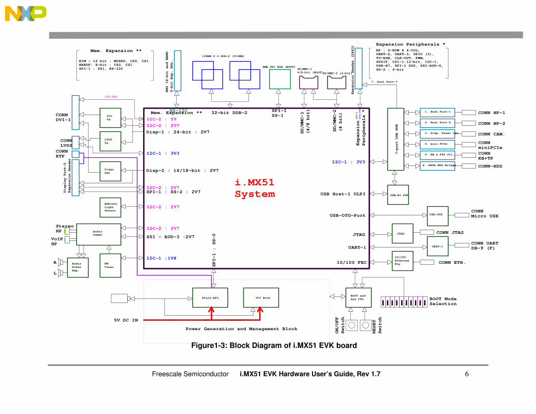
Figure 1-3 shows Block diagram of i.MX51 EVK board.
Freescale Semiconductor i.MX51 EVK Hardware User’s Guide, Rev 1.7 6
Figure1-3: Block Diagram of i.MX51 EVK board
7. Host Port-7
3V3 BuckAtals-APL
Audio
CODEC
FM
Tuner
Audio
Power
Amp.
Ambient
Light
Sensor
Video
DAC
LVDS
Tx
DVI
Tx
Display Port-2
Expansion Header
32-bit DDR-2SPI-1SS-1
SD/MMC-1
(4/8 bit)
SD/MMC-2
(4 bit)
5V DC IN
USB Host-1 ULPI
USB-OTG-Port
JTAG
UART-1
10/100 FEC
SPI-1 : SS-0
Disp-1 : 24-bit : 2V7
Disp-2 : 16/18-bit : 2V7
Expansion
Peripherals *Mem. Expansion **
Expansion Peripherals *
Mem. Expansion ** KP : 4-ROW X 4-COL, UART-2, UART-3, GPIO (3),
TV-RGB, CLK-OUT, PWM, SPDIF, CSI-1:12-bit, I2C-1, USB-H7, SPI-1 SS2, SSI-AUD-6,
SD-2 : 4-bit
EIM - 16 bit : MUXED, CS0, CS1NANDF: 8-bit : CS0, CS1SPI-1 : SS1, HS-I2C
R
L
StereoHP
VoIPHP
I2C-DDC
I2C-2 : 5V
I2C-2 : 2V7
I2C-2 : 2V7
I2C-1 : 3V3
I2C-2 : 2V7
CONN-HDD
CONNKB+TP
CONNminiPCIe
CONN CAM.
CONN HP-2
CONN HP-1
CONNMicro USB
CONN JTAG
CONN UARTDB-9 (F)
I2C-2 : 2V7
CONN ETH.
CONNLVDS
CONNDVI-I
CONNRTP
SPI-1 : SS-2 : 2V7
SSI - AUD-3 :2V7
I2C-1 :1V8
BOOT ModeSelection
ON/OFF
Switch
RESET
Switch
I2C-1 : 3V3
I2C-1
3V3/1V8HS-I2C
i.MX51 System
128MB X 4 DDR-2 (512MB)
4MB SPI NOR (BOOT)SD/MMC-1
4/8-bit (BOOT)SD/MMC-2 (4-bit)
Expansion Header (24X3)
USB-H1 PHY
7-port USB HUB
EMI 16-bit and NAND
8-bit Exp. Hdr.
USB-OTG
UART-1
JTAG
10/100
Ethernet
Phy.
1. Host Port-1
2. Host Port-2
3. Disp. Panel Cam.
4. mini PCIe
5. KB & PS2 Ctl.
6. SATA HDD Bridge
Power Generation and Management Block
BOOT and
Sys CTL
Freescale Semiconductor i.MX51 EVK Hardware User’s Guide, Rev 1.7 7
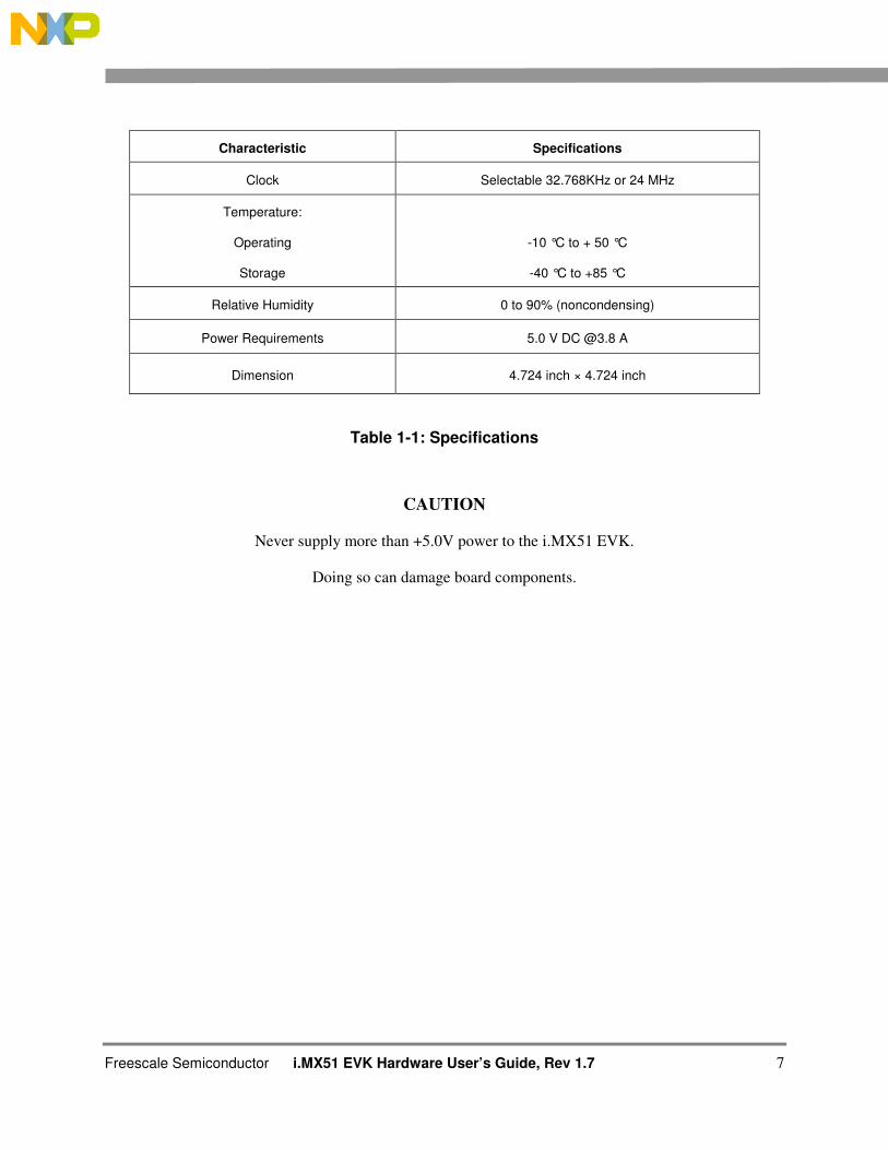
Characteristic Specifications
Clock Selectable 32.768KHz or 24 MHz
Temperature:
Operating
Storage
-10 °C to + 50 °C
-40 °C to +85 °C
Relative Humidity 0 to 90% (noncondensing)
Power Requirements 5.0 V DC @3.8 A
Dimension 4.724 inch × 4.724 inch
Table 1-1: Specifications
CAUTION
Never supply more than +5.0V power to the i.MX51 EVK.
Doing so can damage board components.
Freescale Semiconductor i.MX51 EVK Hardware User’s Guide, Rev 1.7 8
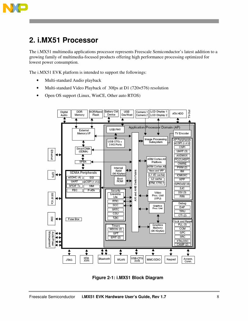
2. i.MX51 Processor
The i.MX51 multimedia applications processor represents Freescale Semiconductor’s latest addition to a
growing family of multimedia-focused products offering high performance processing optimized for
lowest power consumption.
The i.MX51 EVK platform is intended to support the followings:
• Multi-standard Audio playback
• Multi-standard Video Playback of 30fps at D1 (720×576) resolution
• Open OS support (Linux, WinCE, Other auto RTOS)
Figure 2-1: i.MX51 Block Diagram
Freescale Semiconductor i.MX51 EVK Hardware User´s Guide, Rev 1.7 9
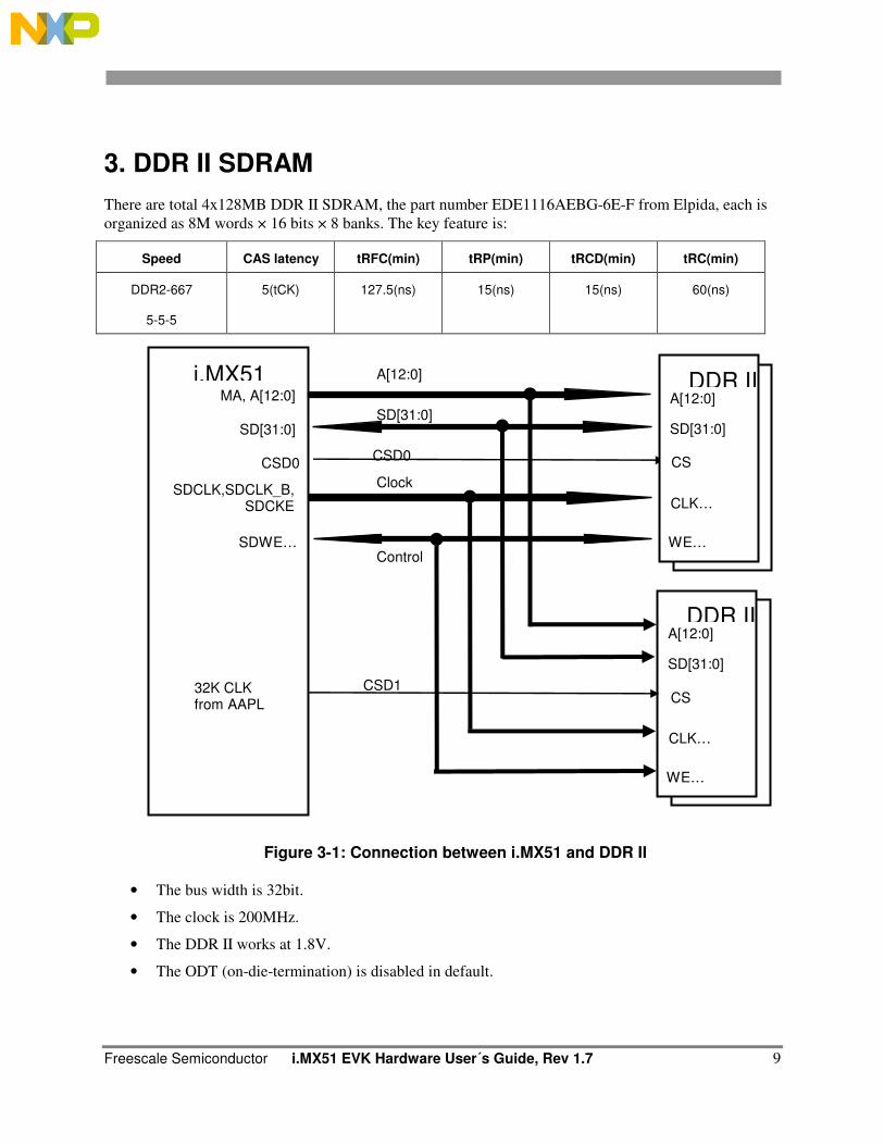
3. DDR II SDRAM
There are total 4x128MB DDR II SDRAM, the part number EDE1116AEBG-6E-F from Elpida, each is
organized as 8M words × 16 bits × 8 banks. The key feature is:
Speed CAS latency tRFC(min) tRP(min) tRCD(min) tRC(min)
DDR2-667
5-5-5
5(tCK) 127.5(ns) 15(ns) 15(ns) 60(ns)
Figure 3-1: Connection between i.MX51 and DDR II
• The bus width is 32bit.
• The clock is 200MHz.
• The DDR II works at 1.8V.
• The ODT (on-die-termination) is disabled in default.
A[12:0]
SD[31:0]
i.MX51 MA, A[12:0]
SD[31:0]
CSD0 CSD0 CS
Control
Clock SDCLK,SDCLK_B,
SDCKE
SDWE…
A[12:0]
SD[31:0]
DDR II
CLK…
WE…
A[12:0]
SD[31:0]
DDR II
CLK…
WE…
CS
CSD1 32K CLK from AAPL CS
Freescale Semiconductor i.MX51 EVK Hardware User’s Guide, Rev 1.7 10
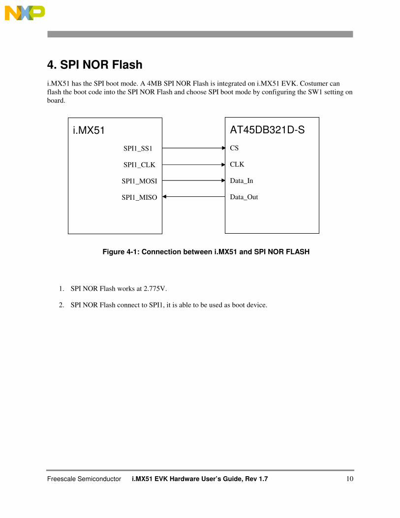
4. SPI NOR Flash
i.MX51 has the SPI boot mode. A 4MB SPI NOR Flash is integrated on i.MX51 EVK. Costumer can
flash the boot code into the SPI NOR Flash and choose SPI boot mode by configuring the SW1 setting on
board.
Figure 4-1: Connection between i.MX51 and SPI NOR FLASH
1. SPI NOR Flash works at 2.775V.
2. SPI NOR Flash connect to SPI1, it is able to be used as boot device.
i.MX51
SPI1_SS1
SPI1_CLK
SPI1_MOSI
SPI1_MISO
AT45DB321D-S
CS
CLK
Data_In
Data_Out
Freescale Semiconductor i.MX51 EVK Hardware User´s Guide, Rev 1.7 11
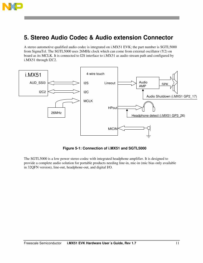
5. Stereo Audio Codec & Audio extension Connector
A stereo automotive qualified audio codec is integrated on i.MX51 EVK; the part number is SGTL5000
from SigmaTel. The SGTL5000 uses 26MHz clock which can come from external oscillator (Y2) on
board as its MCLK. It is connected to I2S interface to i.MX51 as audio stream path and configured by
i.MX51 through I2C2.
Figure 5-1: Connection of i.MX51 and SGTL5000
The SGTL5000 is a low power stereo codec with integrated headphone amplifier. It is designed to
provide a complete audio solution for portable products needing line-in, mic-in (mic bias only available
in 32QFN version), line-out, headphone-out, and digital I/O.
Headphone detect (i.MX51 GP3_26)
Audio Shutdown (i.MX51 GP2_17)
I2S
I2C
MCLK
Lineout
HPout
MICIN
26MHz
Audio AMP
SPK
i.MX51
AUD_SSI3
I2C2
4-wire touch
Freescale Semiconductor i.MX51 EVK Hardware User’s Guide, Rev 1.7 12
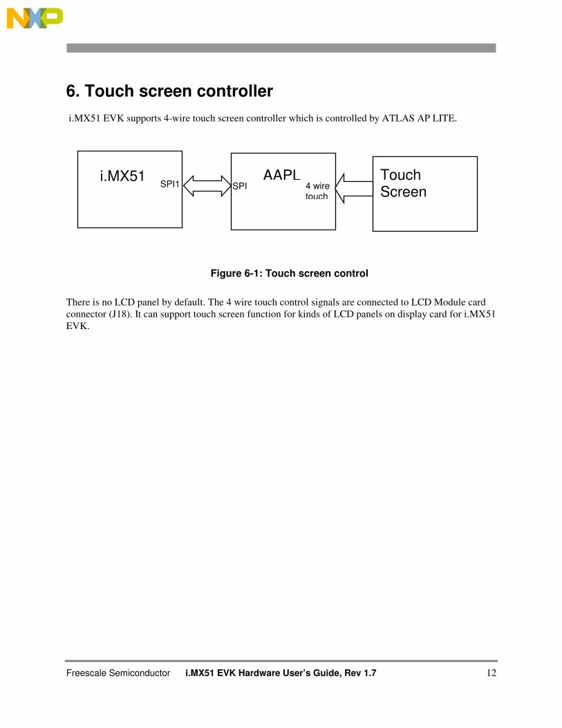
6. Touch screen controller
i.MX51 EVK supports 4-wire touch screen controller which is controlled by ATLAS AP LITE.
Figure 6-1: Touch screen control
There is no LCD panel by default. The 4 wire touch control signals are connected to LCD Module card
connector (J18). It can support touch screen function for kinds of LCD panels on display card for i.MX51
EVK.
AAPL Elvis Touch Screen
SPI1 SPI 4 wire touch
i.MX51
Freescale Semiconductor i.MX51 EVK Hardware User´s Guide, Rev 1.7 13
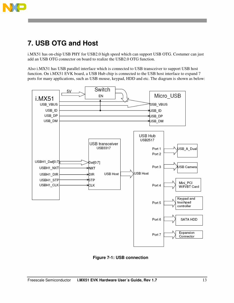
7. USB OTG and Host
i.MX51 has on-chip USB PHY for USB2.0 high speed which can support USB OTG. Costumer can just
add an USB OTG connector on board to realize the USB2.0 OTG function.
Also i.MX51 has USB parallel interface which is connected to USB transceiver to support USB host
function. On i.MX51 EVK board, a USB Hub chip is connected to the USB host interface to expand 7
ports for many applications, such as USB mouse, keypad, HDD and etc. The diagram is shown as below:
Figure 7-1: USB connection
i.MX51
Freescale Semiconductor i.MX51 EVK Hardware User’s Guide, Rev 1.7 14
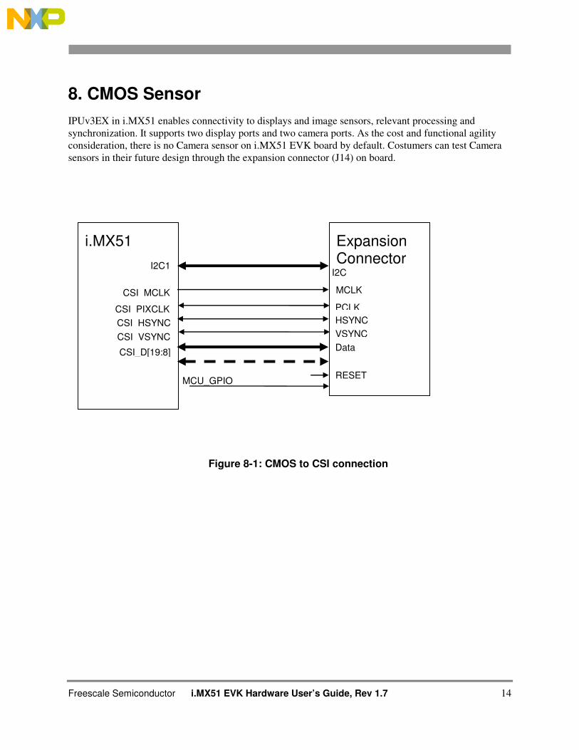
8. CMOS Sensor
IPUv3EX in i.MX51 enables connectivity to displays and image sensors, relevant processing and
synchronization. It supports two display ports and two camera ports. As the cost and functional agility
consideration, there is no Camera sensor on i.MX51 EVK board by default. Costumers can test Camera
sensors in their future design through the expansion connector (J14) on board.
Figure 8-1: CMOS to CSI connection
i.MX51
I2C1
CSI_PIXCLK
CSI_MCLK
MCU_GPIO
Expansion Connector
I2C
CSI_HSYNC
CSI_VSYNC
CSI_D[19:8]
MCLK
PCLK
HSYNC
VSYNC
Data
RESET
Freescale Semiconductor i.MX51 EVK Hardware User´s Guide, Rev 1.7 15
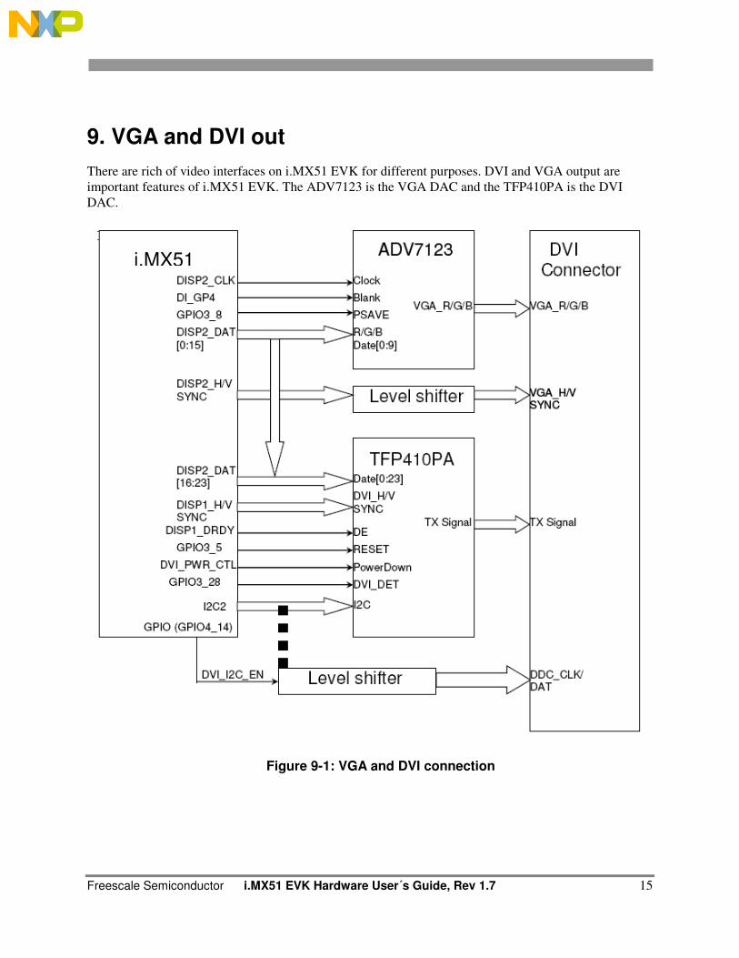
9. VGA and DVI out
There are rich of video interfaces on i.MX51 EVK for different purposes. DVI and VGA output are
important features of i.MX51 EVK. The ADV7123 is the VGA DAC and the TFP410PA is the DVI
DAC.
Figure 9-1: VGA and DVI connection
i.MX51
Freescale Semiconductor i.MX51 EVK Hardware User’s Guide, Rev 1.7 16
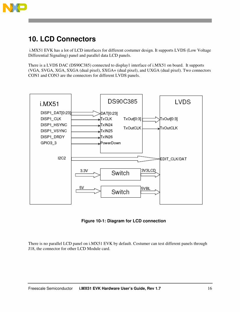
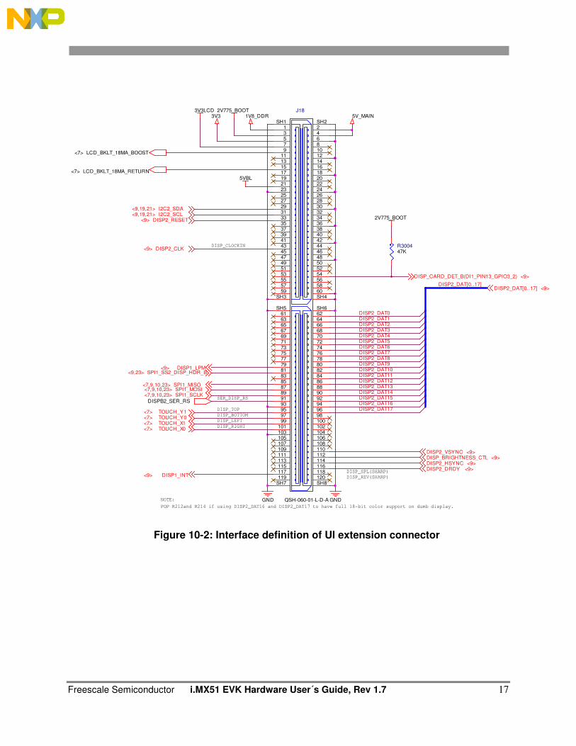
10. LCD Connectors
i.MX51 EVK has a lot of LCD interfaces for different costumer design. It supports LVDS (Low Voltage
Differential Signaling) panel and parallel data LCD panels.
There is a LVDS DAC (DS90C385) connected to display1 interface of i.MX51 on board. It supports
(VGA, SVGA, XGA, SXGA (dual pixel), SXGA+ (dual pixel), and UXGA (dual pixel). Two connectors
CON1 and CON3 are the connectors for different LVDS panels.
Figure 10-1: Diagram for LCD connection
There is no parallel LCD panel on i.MX51 EVK by default. Costumer can test different panels through
J18, the connector for other LCD Module card.
i.MX51
Freescale Semiconductor i.MX51 EVK Hardware User´s Guide, Rev 1.7 17
LCD_BKLT_18MA_BOOST<7>
NOTE:
POP R212and R214 if using DISP2_DAT16 and DISP2_DAT17 to have full 18-bit color support on dumb display.
DISP2_DAT[0..17]
R300447K
DISP1_INT<9>
2V775_BOOT
DISPB2_SER_RS
GND
DISP_CARD_DET_B(DI1_PIN13_GPIO3_2) <9>
2V775_BOOT
3V3 5V_MAIN1V8_DDR
DISP2_VSYNC <9>
DISP2_DAT[0..17] <9>
DISP2_DRDY <9>DISP2_HSYNC <9>
TOUCH_Y1<7>
DISP2_CLK<9>
TOUCH_X1<7>TOUCH_Y0<7>
I2C2_SDA<9,19,21>
TOUCH_X0<7>
SPI1_SS2_DISP_HDR_B<9,23>
I2C2_SCL<9,19,21>
SPI1_MOSI<7,9,10,23>SPI1_SCLK<7,9,10,23>
SPI1_MISO<7,9,10,23>
DISP_BRIGHTNESS_CTL <9>
J18
QSH-060-01-L-D-A
1 23 45 67 89 10
11 1213 1415 1617 1819 2021 2223 2425 2627 2829 3031 3233 3435 3637 3839 4041 4243 4445 4647 4849 5051 5253 5455 5657 5859 60
SH1 SH2
SH3 SH4
SH5 SH6
SH7 SH8
61 6263 6465 6667 6869 7071 7273 7475 7677 7879 8081 8283 8485 8687 8889 9091 9293 9495 9697 9899 100
101 102103 104105 106107 108109 110111 112113 114115 116117 118119 120
DISP2_DAT4DISP2_DAT3DISP2_DAT2
DISP2_DAT5
GND
DISP_CLOCKIN
DISP_BOTTOM
DISP_TOP
DISP_RIGHT
DISP_LEFT
SER_DISP_RS
DISP2_DAT7DISP2_DAT6
DISP_REV(SHARP)
DISP_SPL(SHARP)
DISP2_DAT9
DISP2_DAT11DISP2_DAT10
DISP2_DAT0
DISP2_DAT14DISP2_DAT13DISP2_DAT12
DISP2_DAT1
DISP2_DAT16DISP2_DAT15
DISP2_DAT17
3V3LCD
5VBL
DISP2_RESET<9>
DISP2_DAT8
LCD_BKLT_18MA_RETURN<7>
DISP1_LPM<9>
Figure 10-2: Interface definition of UI extension connector
Freescale Semiconductor i.MX51 EVK Hardware User’s Guide, Rev 1.7 18
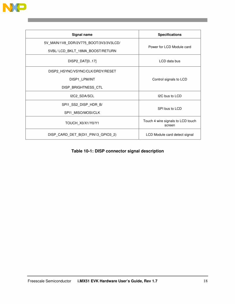
Table 10-1: DISP connector signal description
Signal name Specifications
5V_MAIN/1V8_DDR/2V775_BOOT/3V3/3V3LCD/
5VBL/ LCD_BKLT_18MA_BOOST/RETURN Power for LCD Module card
DISP2_DAT[0..17] LCD data bus
DISP2_HSYNC/VSYNC/CLK/DRDY/RESET
DISP1_LPM/INT
DISP_BRIGHTNESS_CTL
Control signals to LCD
I2C2_SDA/SCL I2C bus to LCD
SPI1_SS2_DISP_HDR_B/
SPI1_MISO/MOSI/CLK SPI bus to LCD
TOUCH_X0/X1/Y0/Y1 Touch 4 wire signals to LCD touch
screen
DISP_CARD_DET_B(DI1_PIN13_GPIO3_2) LCD Module card detect signal
Freescale Semiconductor i.MX51 EVK Hardware User´s Guide, Rev 1.7 19
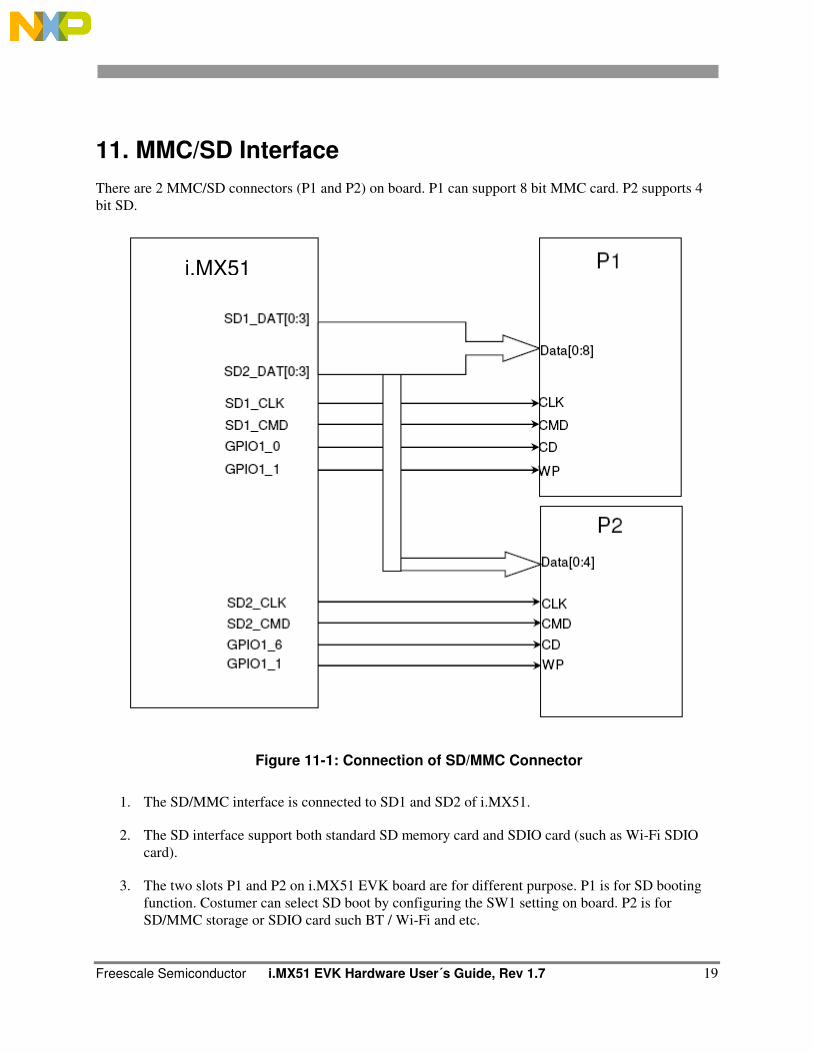
11. MMC/SD Interface
There are 2 MMC/SD connectors (P1 and P2) on board. P1 can support 8 bit MMC card. P2 supports 4
bit SD.
Figure 11-1: Connection of SD/MMC Connector
1. The SD/MMC interface is connected to SD1 and SD2 of i.MX51.
2. The SD interface support both standard SD memory card and SDIO card (such as Wi-Fi SDIO
card).
3. The two slots P1 and P2 on i.MX51 EVK board are for different purpose. P1 is for SD booting
function. Costumer can select SD boot by configuring the SW1 setting on board. P2 is for
SD/MMC storage or SDIO card such BT / Wi-Fi and etc.
i.MX51
Freescale Semiconductor i.MX51 EVK Hardware User’s Guide, Rev 1.7 20
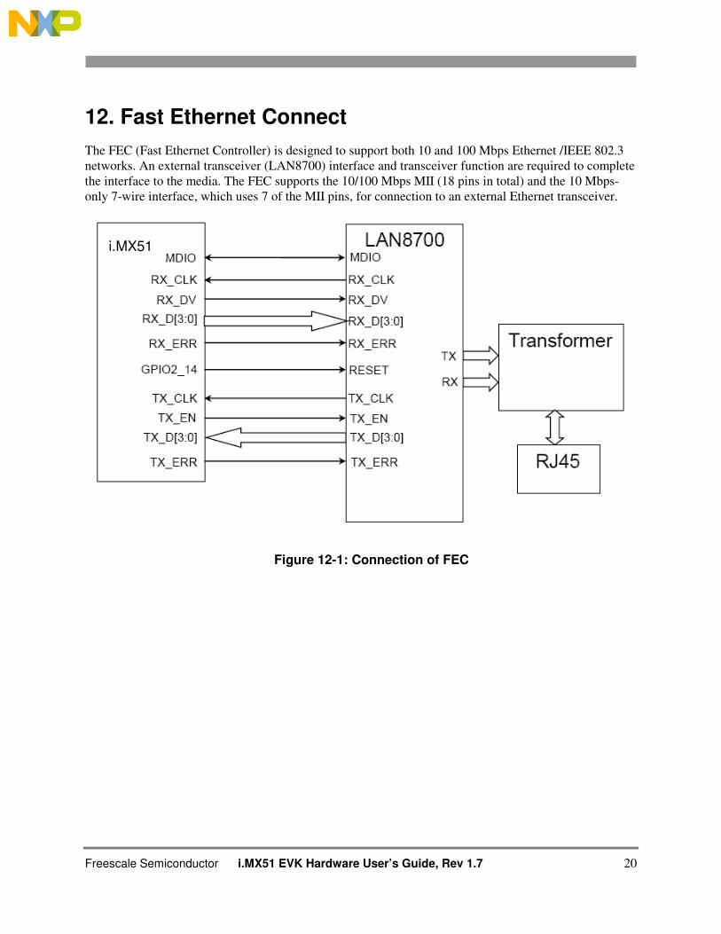
12. Fast Ethernet Connect
The FEC (Fast Ethernet Controller) is designed to support both 10 and 100 Mbps Ethernet /IEEE 802.3
networks. An external transceiver (LAN8700) interface and transceiver function are required to complete
the interface to the media. The FEC supports the 10/100 Mbps MII (18 pins in total) and the 10 Mbps-
only 7-wire interface, which uses 7 of the MII pins, for connection to an external Ethernet transceiver.
Figure 12-1: Connection of FEC
i.MX51
Freescale Semiconductor i.MX51 EVK Hardware User´s Guide, Rev 1.7 21
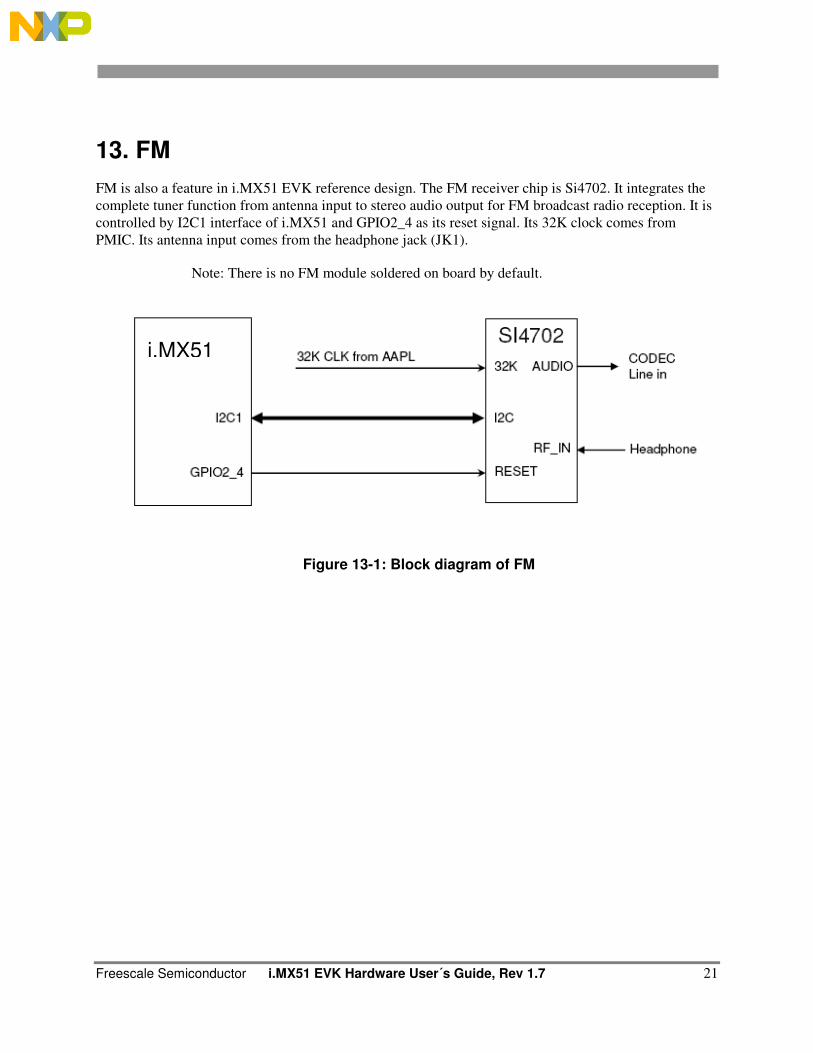
13. FM
FM is also a feature in i.MX51 EVK reference design. The FM receiver chip is Si4702. It integrates the
complete tuner function from antenna input to stereo audio output for FM broadcast radio reception. It is
controlled by I2C1 interface of i.MX51 and GPIO2_4 as its reset signal. Its 32K clock comes from
PMIC. Its antenna input comes from the headphone jack (JK1).
Note: There is no FM module soldered on board by default.
Figure 13-1: Block diagram of FM
i.MX51
Freescale Semiconductor i.MX51 EVK Hardware User’s Guide, Rev 1.7 22
14. Power Supply
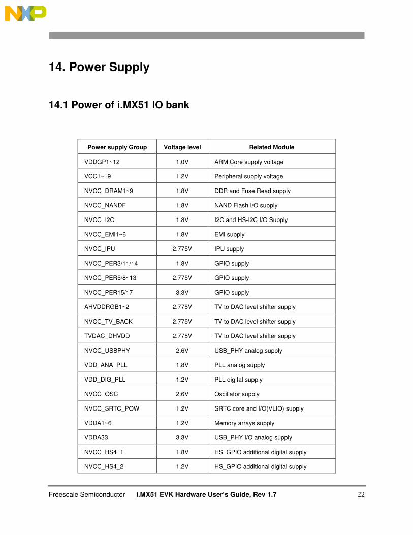
14.1 Power of i.MX51 IO bank
Power supply Group Voltage level Related Module
VDDGP1~12 1.0V ARM Core supply voltage
VCC1~19 1.2V Peripheral supply voltage
NVCC_DRAM1~9 1.8V DDR and Fuse Read supply
NVCC_NANDF 1.8V NAND Flash I/O supply
NVCC_I2C 1.8V I2C and HS-I2C I/O Supply
NVCC_EMI1~6 1.8V EMI supply
NVCC_IPU 2.775V IPU supply
NVCC_PER3/11/14 1.8V GPIO supply
NVCC_PER5/8~13 2.775V GPIO supply
NVCC_PER15/17 3.3V GPIO supply
AHVDDRGB1~2 2.775V TV to DAC level shifter supply
NVCC_TV_BACK 2.775V TV to DAC level shifter supply
TVDAC_DHVDD 2.775V TV to DAC level shifter supply
NVCC_USBPHY 2.6V USB_PHY analog supply
VDD_ANA_PLL 1.8V PLL analog supply
VDD_DIG_PLL 1.2V PLL digital supply
NVCC_OSC 2.6V Oscillator supply
NVCC_SRTC_POW 1.2V SRTC core and I/O(VLIO) supply
VDDA1~6 1.2V Memory arrays supply
VDDA33 3.3V USB_PHY I/O analog supply
NVCC_HS4_1 1.8V HS_GPIO additional digital supply
NVCC_HS4_2 1.2V HS_GPIO additional digital supply
Freescale Semiconductor i.MX51 EVK Hardware User´s Guide, Rev 1.7 23
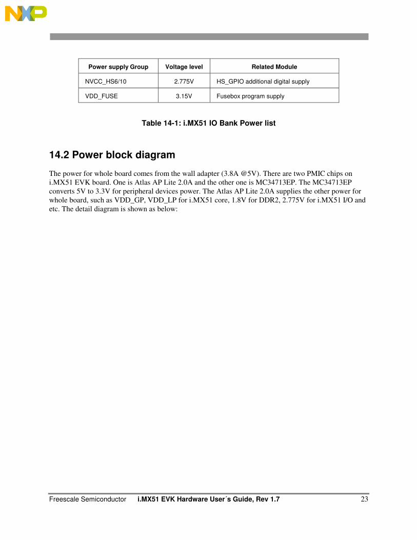
Power supply Group Voltage level Related Module
NVCC_HS6/10 2.775V HS_GPIO additional digital supply
VDD_FUSE 3.15V Fusebox program supply
Table 14-1: i.MX51 IO Bank Power list
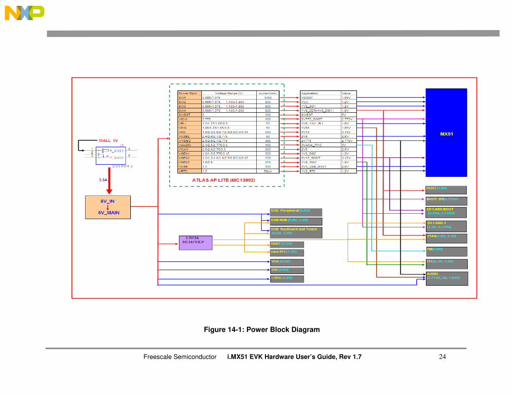
14.2 Power block diagram
The power for whole board comes from the wall adapter (3.8A @5V). There are two PMIC chips on
i.MX51 EVK board. One is Atlas AP Lite 2.0A and the other one is MC34713EP. The MC34713EP
converts 5V to 3.3V for peripheral devices power. The Atlas AP Lite 2.0A supplies the other power for
whole board, such as VDD_GP, VDD_LP for i.MX51 core, 1.8V for DDR2, 2.775V for i.MX51 I/O and
etc. The detail diagram is shown as below:
Freescale Semiconductor i.MX51 EVK Hardware User’s Guide, Rev 1.7 24
Figure 14-1: Power Block Diagram
Freescale Semiconductor i.MX51 EVK Hardware User’s Guide, Rev 1.7 25
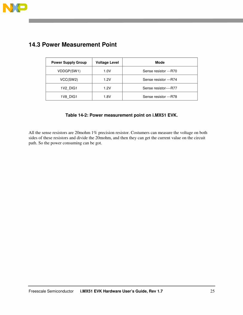
14.3 Power Measurement Point
Power Supply Group Voltage Level Mode
VDDGP(SW1) 1.0V Sense resistor ---R70
VCC(SW2) 1.2V Sense resistor ---R74
1V2_DIG1 1.2V Sense resistor----R77
1V8_DIG1 1.8V Sense resistor ---R78
Table 14-2: Power measurement point on i.MX51 EVK.
All the sense resistors are 20mohm 1% precision resistor. Costumers can measure the voltage on both
sides of these resistors and divide the 20mohm, and then they can get the current value on the circuit
path. So the power consuming can be got.
Freescale Semiconductor i.MX51 EVK Hardware User’s Guide, Rev 1.7 26
15. Accessory boards for i.MX51 EVK
There are a lot of connectors on the i.MX51 EVK board for expansion functions, such as Nand flash,
LCD display, Camera and etc.
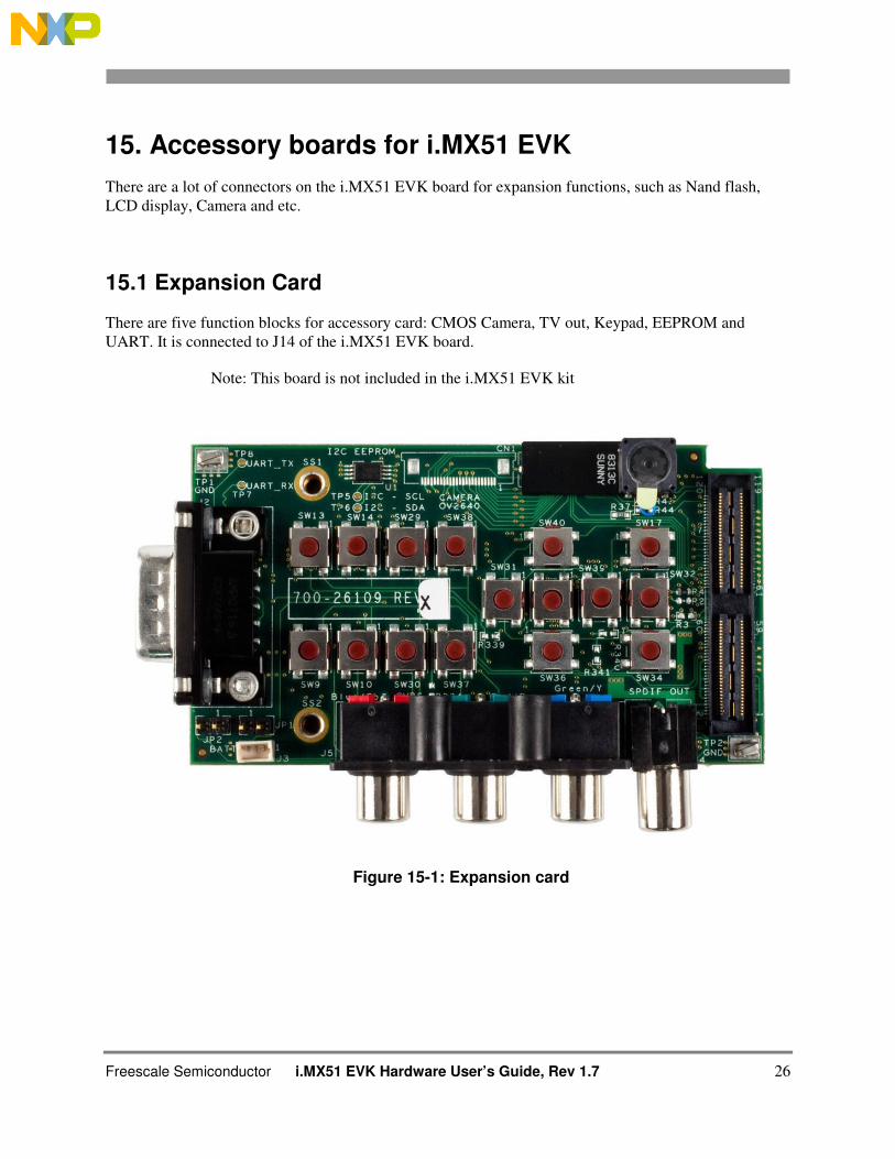
15.1 Expansion Card
There are five function blocks for accessory card: CMOS Camera, TV out, Keypad, EEPROM and
UART. It is connected to J14 of the i.MX51 EVK board.
Note: This board is not included in the i.MX51 EVK kit
Figure 15-1: Expansion card
Freescale Semiconductor i.MX51 EVK Hardware User´s Guide, Rev 1.7 27
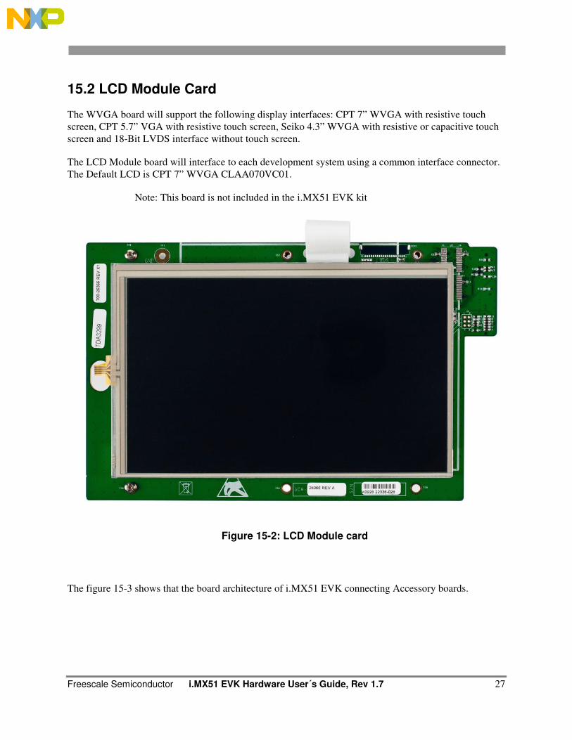
15.2 LCD Module Card
The WVGA board will support the following display interfaces: CPT 7” WVGA with resistive touch
screen, CPT 5.7” VGA with resistive touch screen, Seiko 4.3” WVGA with resistive or capacitive touch
screen and 18-Bit LVDS interface without touch screen.
The LCD Module board will interface to each development system using a common interface connector.
The Default LCD is CPT 7” WVGA CLAA070VC01.
Note: This board is not included in the i.MX51 EVK kit
Figure 15-2: LCD Module card
The figure 15-3 shows that the board architecture of i.MX51 EVK connecting Accessory boards.
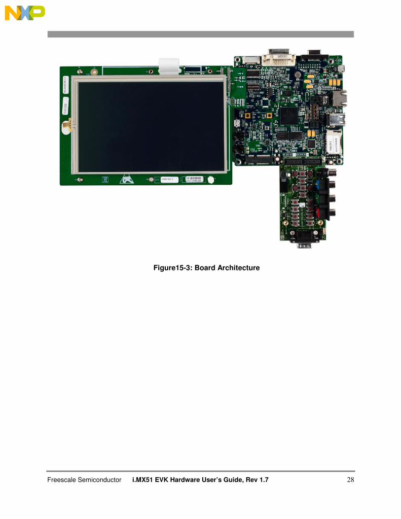
Freescale Semiconductor i.MX51 EVK Hardware User’s Guide, Rev 1.7 28
Figure15-3: Board Architecture
Freescale Semiconductor i.MX51 EVK Hardware User´s Guide, Rev 1.7 29
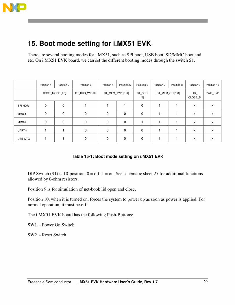
15. Boot mode setting for i.MX51 EVK
There are several booting modes for i.MX51, such as SPI boot, USB boot, SD/MMC boot and
etc. On i.MX51 EVK board, we can set the different booting modes through the switch S1.
Table 15-1: Boot mode setting on i.MX51 EVK
DIP Switch (S1) is 10-position. 0 = off, 1 = on. See schematic sheet 25 for additional functions
allowed by 0-ohm resistors.
Position 9 is for simulation of net-book lid open and close.
Position 10, when it is turned on, forces the system to power up as soon as power is applied. For
normal operation, it must be off.
The i.MX51 EVK board has the following Push-Buttons:
SW1. - Power On Switch
SW2. - Reset Switch
Position 1 Position 2 Position 3 Position 4 Position 5 Position 6 Position 7 Position 8 Position 9 Position 10
BOOT_MODE [1:0] BT_BUS_WIDTH BT_MEM_TYPE[1:0] BT_SRC
[0]
BT_MEM_CTL[1:0] LID_
CLOSE_B
PWR_BYP
SPI-NOR 0 0 1 1 1 0 1 1 x x
MMC-1 0 0 0 0 0 0 1 1 x x
MMC-2 0 0 0 0 0 1 1 1 x x
UART-1 1 1 0 0 0 0 1 1 x x
USB-OTG 1 1 0 0 0 0 1 1 x x
Freescale Semiconductor i.MX51 EVK Hardware User’s Guide, Rev 1.7 30
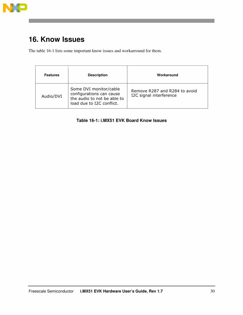
16. Know Issues
The table 16-1 lists some important know issues and workarround for them.
Features Description Workaround
Audio/DVI
Some DVI monitor/cable configurations can cause the audio to not be able to load due to I2C conflict.
Remove R287 and R284 to avoid I2C signal interference
Table 16-1: i.MX51 EVK Board Know Issues