Embed Size (px)
Citation preview
Quick Start Guide
i.MX 8M Quad Evaluation Kit
2
GET TO KNOW THE i.MX 8M QUAD EVK
Quick Start Guide
Figure 1: Front side of i.MX 8M Quad EVK (top)
ON/OFF Button
Debug portDebug port LEDs
BOOT MODE switchBOOT DEVICE switch
RESET Button
MIPI-CSI1 Connector
MIPI-CSI2 Connector
MIPI-DSI Connector
Power Switch
USB Type-C Connector
DC Jack for 12V power
input USB Type-A Connector
1 Gbps Ethernet
Connector
HDMI Connector
3.5 mm Audio Jack
Infrared Receiver JTAG
Connector
SD Card ConnectorPower
Indication LED
3
www.nxp.com
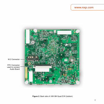
Figure 2: Back side of i.MX 8M Quad EVK (bottom)
M.2 Connector
FPC Connector used to connect
Audio Board
4
Quick Start Guide
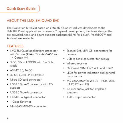
ABOUT THE i.MX 8M QUAD EVK
The Evaluation Kit (EVK) based on i.MX 8M Quad introduces developers to the i.MX 8M Quad applications processor. To speed development, hardware design files are provided, tools and board support packages (BSPs) for Linux®, FreeRTOS™ and Android are available.
FEATURES• i.MX 8M Quad applications processor
with 5 cores (4×Arm® Cortex®-A53 and 1× Cortex-M4)
• 3 GB, 32-bit LPDDR4 with 1.6 GHz clock
• eMMC 5.0, 16 GB
• 32 MB Octal SPI NOR flash
• Micro SD card connector
• USB3.0 Type-C connector with PD support
• USB3.0 Type-A connector
• HDMI2.0a Type-A connector
• 1 Gbps Ethernet
• Mini-SAS MIPI-DSI connector
• 2x mini-SAS MIPI-CSI connectors for camera
• USB to serial convertor for debug
• Infrared receiver
• On-board MIMO 2x2 WiFi and BT4.2
• LEDs for power indication and general-purpose use
• M.2 connector for WiFi/BT (PCIe, USB, UART, I2C and I2S)
• 3.5 mm audio jack for amplified speakers
• JTAG 10-pin connector
5
www.nxp.com
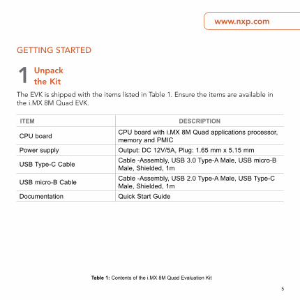
GETTING STARTED
ITEM DESCRIPTION
CPU board CPU board with i.MX 8M Quad applications processor, memory and PMIC
Power supply Output: DC 12V/5A, Plug: 1.65 mm x 5.15 mm
USB Type-C Cable Cable -Assembly, USB 3.0 Type-A Male, USB micro-B Male, Shielded, 1m
USB micro-B Cable Cable -Assembly, USB 2.0 Type-A Male, USB Type-C Male, Shielded, 1m
Documentation Quick Start Guide
1 Unpack the Kit
The EVK is shipped with the items listed in Table 1. Ensure the items are available in the i.MX 8M Quad EVK.
Table 1: Contents of the i.MX 8M Quad Evaluation Kit
6
Quick Start Guide
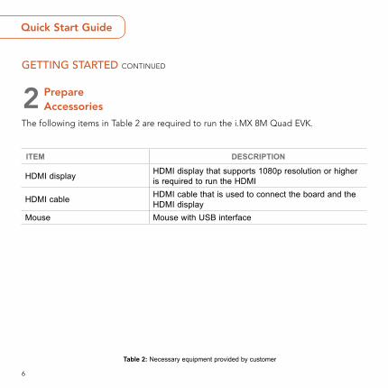
GETTING STARTED CONTINUED
ITEM DESCRIPTION
HDMI display HDMI display that supports 1080p resolution or higher is required to run the HDMI
HDMI cable HDMI cable that is used to connect the board and the HDMI display
Mouse Mouse with USB interface
2 Prepare Accessories
The following items in Table 2 are required to run the i.MX 8M Quad EVK.
Table 2: Necessary equipment provided by customer
7
www.nxp.com
GETTING STARTED CONTINUED
ITEM DESCRIPTION
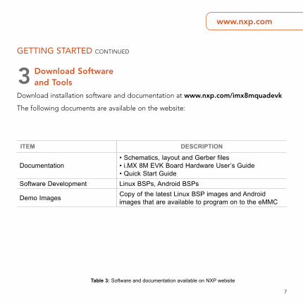
Documentation• Schematics, layout and Gerber files • i.MX 8M EVK Board Hardware User’s Guide • Quick Start Guide
Software Development Linux BSPs, Android BSPs
Demo Images Copy of the latest Linux BSP images and Android images that are available to program on to the eMMC
3 Download Software and Tools
Download installation software and documentation at www.nxp.com/imx8mquadevk
The following documents are available on the website:
Table 3: Software and documentation available on NXP website
8
Quick Start Guide
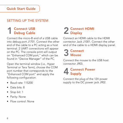
SETTING UP THE SYSTEM
1 Connect USB Debug Cable
Connect the micro-B end of a USB cable into debug port J1701. Connect the other end of the cable to a PC acting as a host terminal. 2 UART connections will appear on the PC. The console print will output on “Enhanced COM port,” which can be found in “Device Manager” of the PC.
Open the terminal window (i.e., Hyper Terminal or Tera Term), choose the COM port number that corresponds to the “Enhanced COM port” and apply the following configuration.
• Baud rate: 115200
• Data bits: 8
• Stop bit: 1
• Parity: None
• Flow control: None
2 Connect HDMI Display
Connect an HDMI cable to the HDMI connector Jack J1001. Connect the other end of the cable to a HDMI display panel.
3 Connect Mouse
Connect the mouse to the USB host connector J903.
4 Connect Power Supply
Connect the plug of the 12V power supply to the DC power jack J902.
9
www.nxp.com
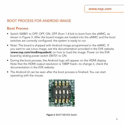
BOOT PROCESS FOR ANDROID IMAGE
Boot Process
• Switch SW801 to OFF, OFF, ON, OFF (from 1-4 bit) to boot from the eMMC, as shown in Figure 3. After the board images are loaded into the eMMC and the boot switches are correctly configured, the system is ready to run.
• Note: The board is shipped with Android image programmed in the eMMC. If you want to use Linux image, see the documentation provided in the EVK website (www.nxp.com/imx8mquadevk) on how to load the image. Power on the EVK board by sliding power switch SW701 to ON.
• During the boot process, the Android logo will appear on the HDMI display. Note that the HDMI output resolution is 1080P fixed—to change it, check the documentation in the EVK website.
• The Android UI can be seen after the boot process is finished. You can start operating with the mouse.
Figure 3: BOOT DEVICE Switch
10
Quick Start Guide
This device complies with Part 15 of the FCC Rules. Operation is subject to the following two conditions:
(1) This device may not cause harmful interference, and
(2) This device must accept any interference received, including interference that may cause undesired operation.
Attention that changes or modification not expressly approved by the party responsible for compliance could void the user’s authority to operate the equipment.
Note: This product has been tested and found to comply with the limits for a Class B digital device, pursuant to Part 15 of the FCC Rules. These limits are designed to provide reasonable protection against harmful interference in a residential installation. This product generates, uses, and can radiate radio frequency energy and, if not installed and used in accordance with the instructions, may cause harmful interference to radio communications. However, there is no guarantee that interference will not occur in a particular installation. If this product does cause harmful interference to radio or television reception, which can be determined by turning the equipment off and on, the user is encouraged to try to correct the interference by one or more of the following measures:
—Reorient or relocate the receiving antenna.
— Increase the separation between the equipment and receiver.
— Connect the equipment into an outlet on a circuit different from that to which the receiver is connected.
— Consult the dealer or an experienced radio/TV technician for help.
This equipment should be installed and operated with a minimum distance 20cm between the radiator and your body.


SUPPORTVisit the i.MX community at www.imxcommunity.org.
WARRANTYVisit www.nxp.com/warranty for complete warranty information.
www.nxp.com/iMX8MQuadEVK
NXP and the NXP logo are trademarks of NXP B.V. All other product or service names are the property of their respective owners. Arm and Cortex are registered trademarks of Arm Limited (or its subsidiaries) in the EU and/or elsewhere. All rights reserved. © 2018 NXP B.V.
Document Number: IMX8MQUADEVKQSG REV 0 Agile Number: 926-29615 REV A


![USB contacts - Encitech€¦ · USB 2.0-Cable End 1: Panel Connector with USB 2.0 Type A End 2: Plug, USB 2.0 Typ A Length USB 2.0-Panel mount connector with Cable [m] 0,5 1310-0004-01](https://img.pdfslide.us/doc/110x75/6069a908fdc9b44193738fb0/usb-contacts-encitech-usb-20-cable-end-1-panel-connector-with-usb-20-type-a.jpg)