Embed Size (px)
Citation preview

IMT, INC. 31
6450 University Blvd, Ste 1, Winter Park, FL 32792 877-679-2217 Fax: 407-679-1114
6450 University Blvd, Ste 1, Winter Park, FL 32792 877-679-2217 Fax: 407-679-1114
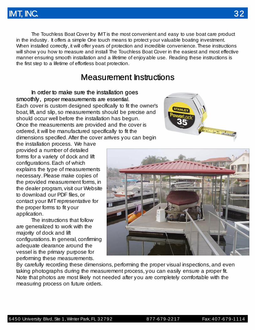
The Touchless Boat Cover by IMT is the most convenient and easy to use boat care product in the industry. It offers a simple One touch means to protect your valuable boating investment. When installed correctly, it will offer years of protection and incredible convenience. These instructions will show you how to measure and install The Touchless Boat Cover in the easiest and most effective manner ensuring smooth installation and a lifetime of enjoyable use. Reading these instructions is the first step to a lifetime of effortless boat protection.
Measurement Instructions
In order to make sure the installation goes smoothly, proper measurements are essential. Each cover is custom designed specifically to fit the owner’s boat, lift, and slip, so measurements should be precise and should occur well before the installation has begun. Once the measurements are provided and the cover is ordered, it will be manufactured specifically to fit the dimensions specified. After the cover arrives you can begin the installation process. We have provided a number of detailed forms for a variety of dock and lift configurations. Each of which explains the type of measurements necessary. Please make copies of the provided measurement forms, in the dealer program, visit our Website to download our PDF files, or contact your IMT representative for the proper forms to fit your application. The instructions that follow are generalized to work with the majority of dock and lift configurations. In general, confirming adequate clearance around the vessel is the primary purpose for performing these measurements. By carefully recording these dimensions, performing the proper visual inspections, and even taking photographs during the measurement process, you can easily ensure a proper fit. Note that photos are most likely not needed after you are completely comfortable with the measuring process on future orders.
IMT, INC. 32
6450 University Blvd, Ste 1, Winter Park, FL 32792 877-679-2217 Fax: 407-679-1114
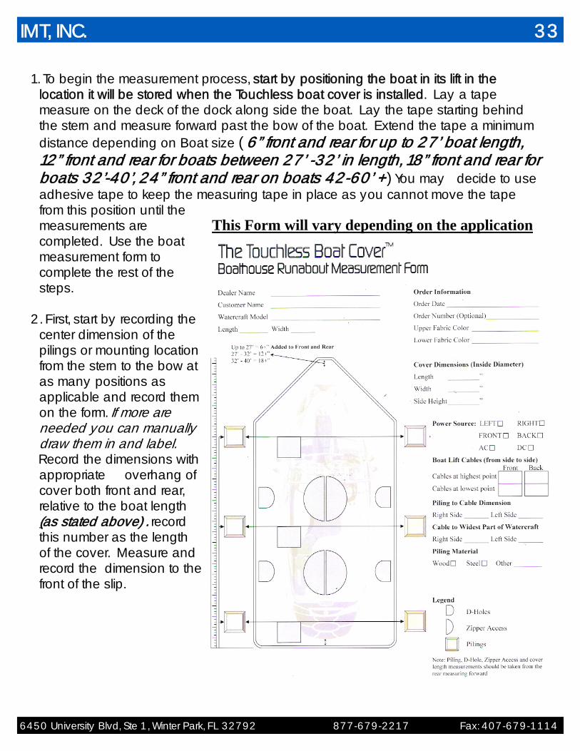
1. To begin the measurement process, start by positioning the boat in its lift in the location it will be stored when the Touchless boat cover is installed. Lay a tape measure on the deck of the dock along side the boat. Lay the tape starting behind the stern and measure forward past the bow of the boat. Extend the tape a minimum distance depending on Boat size ( 6” front and rear for up to 27’ boat length, 12” front and rear for boats between 27’ -32’ in length, 18” front and rear for boats 32’-40’, 24” front and rear on boats 42-60’ +) You may decide to use adhesive tape to keep the measuring tape in place as you cannot move the tape from this position until the measurements are completed. Use the boat measurement form to complete the rest of the steps.
2. First, start by recording the
center dimension of the pilings or mounting location from the stern to the bow at as many positions as applicable and record them on the form. If more are needed you can manually draw them in and label.
Record the dimensions with appropriate overhang of cover both front and rear, relative to the boat length (as stated above) . record this number as the length of the cover. Measure and record the dimension to the front of the slip.
This Form will vary depending on the application
IMT, INC. 33
6450 University Blvd, Ste 1, Winter Park, FL 32792 877-679-2217 Fax: 407-679-1114
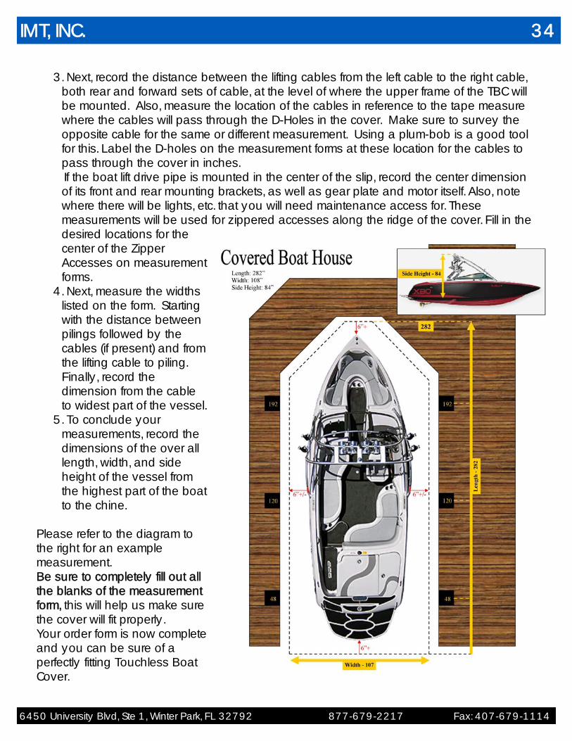
3. Next, record the distance between the lifting cables from the left cable to the right cable, both rear and forward sets of cable, at the level of where the upper frame of the TBC will be mounted. Also, measure the location of the cables in reference to the tape measure where the cables will pass through the D-Holes in the cover. Make sure to survey the opposite cable for the same or different measurement. Using a plum-bob is a good tool for this. Label the D-holes on the measurement forms at these location for the cables to pass through the cover in inches.
If the boat lift drive pipe is mounted in the center of the slip, record the center dimension of its front and rear mounting brackets, as well as gear plate and motor itself. Also, note where there will be lights, etc. that you will need maintenance access for. These measurements will be used for zippered accesses along the ridge of the cover. Fill in the desired locations for the center of the Zipper Accesses on measurement forms.
4. Next, measure the widths listed on the form. Starting with the distance between pilings followed by the cables (if present) and from the lifting cable to piling. Finally, record the dimension from the cable to widest part of the vessel.
5. To conclude your measurements, record the dimensions of the over all length, width, and side height of the vessel from the highest part of the boat to the chine.
Please refer to the diagram to the right for an example measurement. Be sure to completely fill out all the blanks of the measurement form, this will help us make sure the cover will fit properly. Your order form is now complete and you can be sure of a perfectly fitting Touchless Boat Cover.
IMT, INC. 34
6450 University Blvd, Ste 1, Winter Park, FL 32792 877-679-2217 Fax: 407-679-1114
Installation Instructions
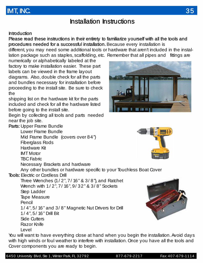
Introduction Please read these instructions in their entirety to familiarize yourself with all the tools and procedures needed for a successful installation. Because every installation is different, you may need some additional tools or hardware that aren’t included in the instal-lation package such as staples, scaffolding, etc. Remember that all pipes and fittings are numerically or alphabetically labeled at the factory to make installation easier. These part labels can be viewed in the frame layout diagrams. Also, double check for all the parts and bundles necessary for installation before proceeding to the install site. Be sure to check the shipping list on the hardware kit for the parts included and check for all the hardware listed before going to the install site. Begin by collecting all tools and parts needed near the job site. Parts: Upper Frame Bundle Lower Frame Bundle Mid Frame Bundle (covers over 84”) Fiberglass Rods Hardware Kit IMT Motor TBC Fabric Necessary Brackets and hardware
Any other bundles or hardware specific to your Touchless Boat Cover Tools: Electric or Cordless Drill
Three Wrenches (1/2”, 7/16” & 3/8”), and Ratchet Wrench with 1/2”, 7/16”, 9/32” & 3/8” Sockets Step Ladder Tape Measure Pencil 1/4”, 5/16” and 3/8” Magnetic Nut Drivers for Drill 1/4”, 5/16” Drill Bit Side Cutters Razor Knife Level
You will want to have everything close at hand when you begin the installation. Avoid days with high winds or foul weather to interfere with installation. Once you have all the tools and Cover components you are ready to begin.
IMT, INC. 35

6450 University Blvd, Ste 1, Winter Park, FL 32792 877-679-2217 Fax: 407-679-1114
Step I – Positioning the boat
1. Position the boat on the lift, in the slip according to the manufacturer’s recommen-dations in the same position that it will be commonly stored. Pull it as far forward as possible as recommended by the manufacturer. Center boat from side to side on the cradle. Make sure that there is sufficient clearance under the boat for props, skegs, etc.
2. Mark the boat’s front and rear position using a pencil. 3. Then temporarily remove the boat from the slip and properly secure the vessel to
a safe area. (Note on Boat house overhead lifts- in order to make for a cleaner installation and provide adequate clearance, it may be necessary to cut and re-swage the boat lift cables and remove the lift weights prior to installing the brackets). Make sure to follow manufacturer’s recommendations and use proper
tools and parts when doing this step.
IMT, INC. 36
6450 University Blvd, Ste 1, Winter Park, FL 32792 877-679-2217 Fax: 407-679-1114
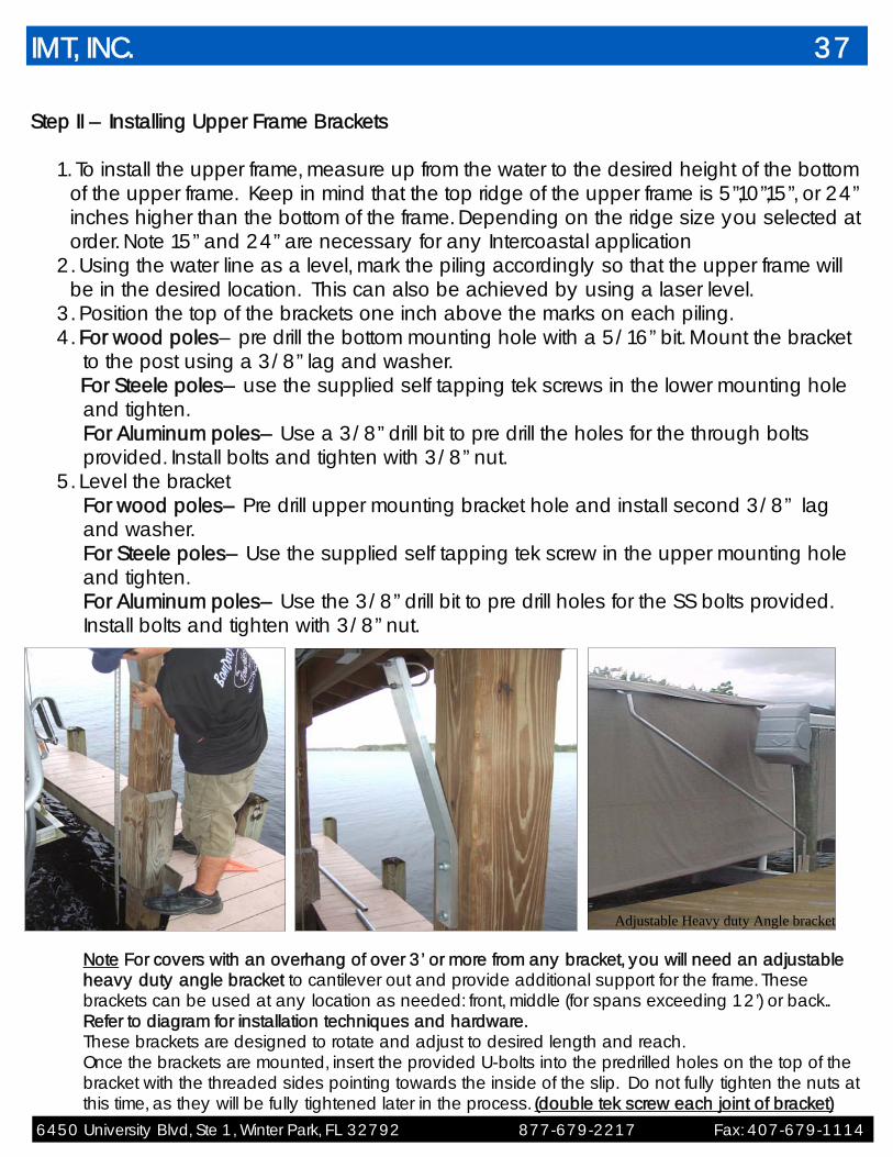
Step II – Installing Upper Frame Brackets
1. To install the upper frame, measure up from the water to the desired height of the bottom of the upper frame. Keep in mind that the top ridge of the upper frame is 5”,10”,15”, or 24” inches higher than the bottom of the frame. Depending on the ridge size you selected at order. Note 15” and 24” are necessary for any Intercoastal application
2. Using the water line as a level, mark the piling accordingly so that the upper frame will be in the desired location. This can also be achieved by using a laser level.
3. Position the top of the brackets one inch above the marks on each piling. 4. For wood poles– pre drill the bottom mounting hole with a 5/16” bit. Mount the bracket
to the post using a 3/8” lag and washer. For Steele poles– use the supplied self tapping tek screws in the lower mounting hole
and tighten. For Aluminum poles– Use a 3/8” drill bit to pre drill the holes for the through bolts provided. Install bolts and tighten with 3/8” nut.
5. Level the bracket For wood poles– Pre drill upper mounting bracket hole and install second 3/8” lag
and washer. For Steele poles– Use the supplied self tapping tek screw in the upper mounting hole and tighten. For Aluminum poles– Use the 3/8” drill bit to pre drill holes for the SS bolts provided. Install bolts and tighten with 3/8” nut.
Note For covers with an overhang of over 3’ or more from any bracket, you will need an adjustable heavy duty angle bracket to cantilever out and provide additional support for the frame. These brackets can be used at any location as needed: front, middle (for spans exceeding 12’) or back.. Refer to diagram for installation techniques and hardware. These brackets are designed to rotate and adjust to desired length and reach. Once the brackets are mounted, insert the provided U-bolts into the predrilled holes on the top of the bracket with the threaded sides pointing towards the inside of the slip. Do not fully tighten the nuts at this time, as they will be fully tightened later in the process. (double tek screw each joint of bracket)
IMT, INC. 37
Adjustable Heavy duty Angle bracket
6450 University Blvd, Ste 1, Winter Park, FL 32792 877-679-2217 Fax: 407-679-1114
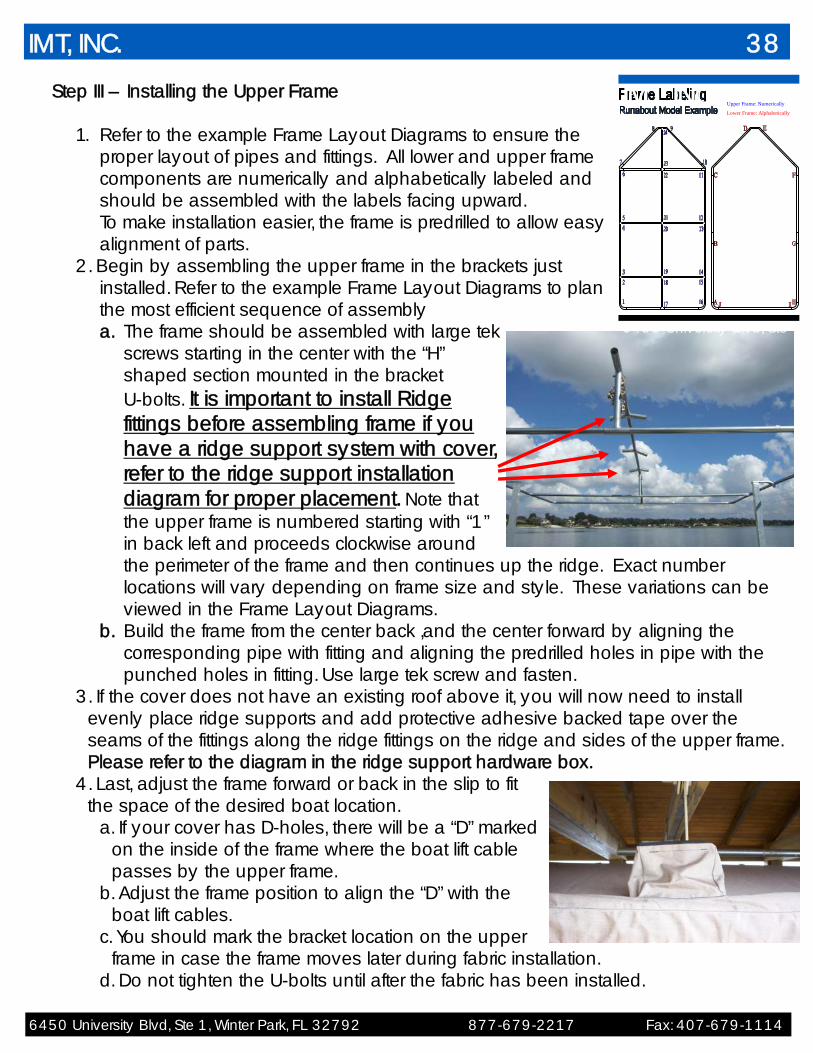
Step III – Installing the Upper Frame
1. Refer to the example Frame Layout Diagrams to ensure the proper layout of pipes and fittings. All lower and upper frame components are numerically and alphabetically labeled and should be assembled with the labels facing upward. To make installation easier, the frame is predrilled to allow easy alignment of parts.
2. Begin by assembling the upper frame in the brackets just installed. Refer to the example Frame Layout Diagrams to plan the most efficient sequence of assembly a. The frame should be assembled with large tek
screws starting in the center with the “H” shaped section mounted in the bracket U-bolts. It is important to install Ridge fittings before assembling frame if you have a ridge support system with cover, refer to the ridge support installation diagram for proper placement. Note that the upper frame is numbered starting with “1” in back left and proceeds clockwise around the perimeter of the frame and then continues up the ridge. Exact number locations will vary depending on frame size and style. These variations can be viewed in the Frame Layout Diagrams.
b. Build the frame from the center back ,and the center forward by aligning the corresponding pipe with fitting and aligning the predrilled holes in pipe with the punched holes in fitting. Use large tek screw and fasten.
3. If the cover does not have an existing roof above it, you will now need to install evenly place ridge supports and add protective adhesive backed tape over the seams of the fittings along the ridge fittings on the ridge and sides of the upper frame. Please refer to the diagram in the ridge support hardware box.
4. Last, adjust the frame forward or back in the slip to fit the space of the desired boat location.
a. If your cover has D-holes, there will be a “D” marked on the inside of the frame where the boat lift cable passes by the upper frame.
b. Adjust the frame position to align the “D” with the boat lift cables.
c. You should mark the bracket location on the upper frame in case the frame moves later during fabric installation.
d. Do not tighten the U-bolts until after the fabric has been installed.
IMT, INC. 38
6450 University Blvd, Ste
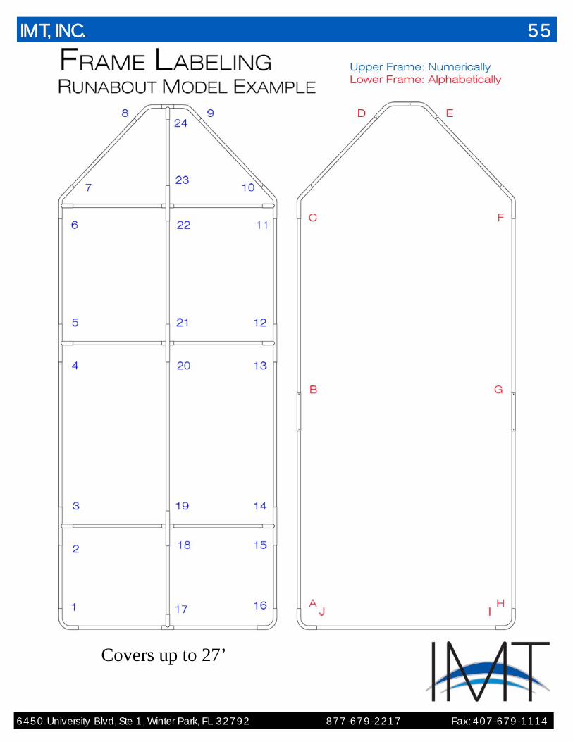
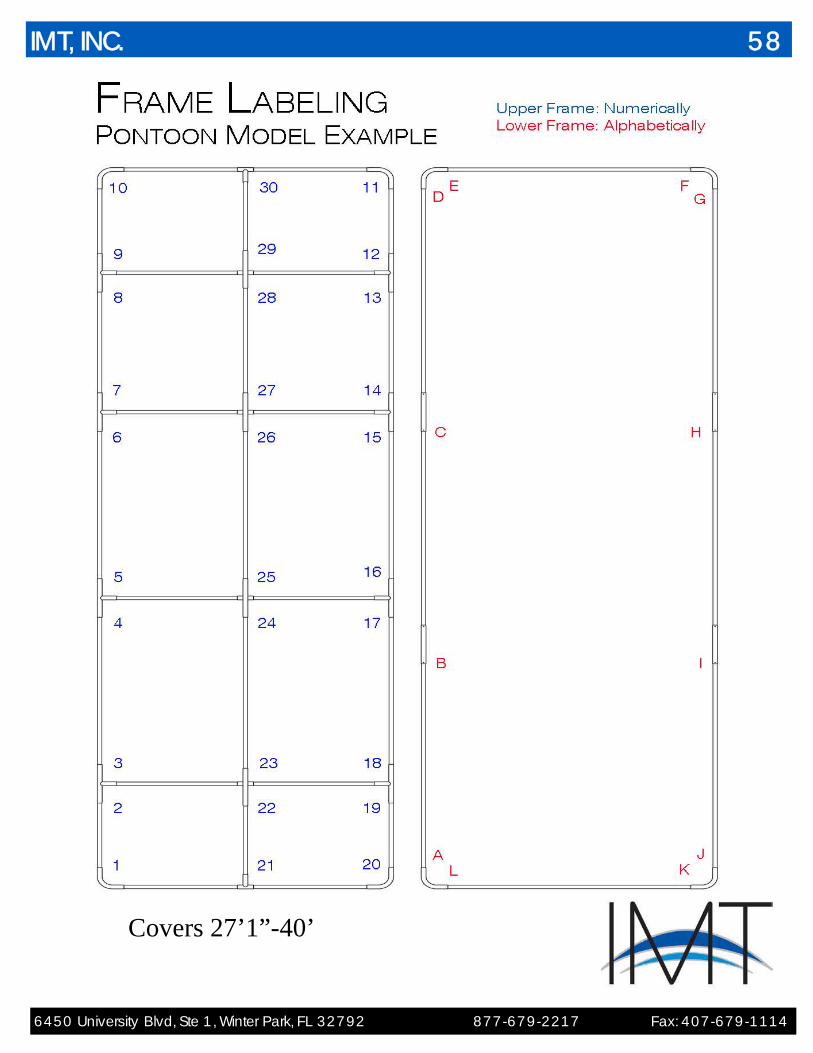
Upper Frame: Numerically
Lower Frame: Alphabetically
IMT, INC.

6450 University Blvd, Ste 1, Winter Park, FL 32792 877-679-2217 Fax: 407-679-1114
Step IV – Installing the Support Cable
1. If the boat lift is covered or roofed, you will next install the upper frame’s support cable.
a. First locate the 60” support cable assembly in the hardware kit. b. Install eyebolt provided with Quick link in the assembly package in upper frame
(the eyebolt hole is located approximately 7” from the nose of the frame in the middle of the ridge pipe on runabouts and 2 holes - 24” off the ridge on each side of the front cross-member on pontoon shaped covers. Tighten eyebolt nuts.
c. Next, drill ¼” hole in the wood beam directly above the location of each of the support cables. Remove the nut from the eye bolt and install the eyebolt in the predrilled hole. Reinstall the nut to the end of the eyebolt and tighten.
d. Then take the opposite end of the cable assembly, holding the nose of the frame level, pull cable tight, parallel to the roof beam, and complete the cable installation by drilling the woodscrew through the thimble of the cable into the beam. NOTE : For covers exceeding 27’ it is necessary to remove the setting eyebolt from the assembly and adjust the cable manually. Cut and swage cable to desired length and bolt or Lag directly into beam. A multi swage tool is required and can be easily purchased at most hardware stores for less than $40.00
IMT, INC. 39

6450 University Blvd, Ste 1, Winter Park, FL 32792 877-679-2217 Fax: 407-679-1114
Step V – Preparing the Boat Cover Fabric
Start by taking the top fabric out The side fabric should be put aside for later installation. It will attach to the top fabric
once installed on the frame with a zipper. Make sure to save the warranty package information to give to the customer later. Once unfolded, the top fabric should resemble a tube.. The Top fabric will be laid on the front of the frame and unroll on the frame as you work to the back of the Frame
Step VI – Installing the Boat Cover Fabric
1. You will begin by laying the top fabric over the upper frame. a. Lay the top Fabric across the front of the frame first and begin unrolling the
Fabric on the upper frame towards the back of the boat until you reach the first set of cables. Always be careful of boatlift gear plates and pipe bearings to avoid getting grease on the fabric while unfolding (boatlift application with cables and gear plate).
b. If your boat lift cables are inside the upper frame and you do have d-holes, the boat should already be off the lift.
c. remove boat lift cable from cradle or slings and feed through D-holes in locations where boat lift cables come through cover. Reconnect cables to cradle or slings and continue unrolling cover until all cables are through cover and cradle or slings are reconnected
IMT, INC. 40

6450 University Blvd, Ste 1, Winter Park, FL 32792 877-679-2217 Fax: 407-679-1114
d. If the cover has no D-holes, continue unrolling the fabric to the back of the frame until it hangs freely.
e. If you have a roofed or covered dock, disconnect the support cable eyebolt from the front ridge pipe. Line up the sewn opening in the fabric over the predrilled hole and reinstall the eyebolt. Make sure at this point to refer to the mark on the upper frame to ensure the frame has not moved from its original position. NOTE: if there are no sewn openings in fabric for support cable eyebolt but a support cable is being utilized, Mark fabric where support cable eyebolt will come through fabric and cut hole with a razor knife large enough to get eyebolt through fabric. Use an area washer on the eyebolt to cover the hole.. The fabric should be secured tightly to the frame.
2. Lift the vent flap at the brackets and using a razor knife, make a slit in the mesh
the width of the bracket, approximately ½” above the lower seem of the mesh. Be careful not to cut the boat cover Top material as you do so.
a. Remove the u-bolt and slide the fabric between the bracket and the upper frame.
b. Insert the bracket through the slit in the mesh vent fabric and reconnect and tighten the u-bolt.
c. Repeat for all the remaining brackets.
3. Once this is done, installation is completed by tight-ening all the u-bolts, and installing the rubber boots on the ends to protect the fabric.
IMT, INC. 41
6450 University Blvd, Ste 1, Winter Park, FL 32792 877-679-2217 Fax: 407-679-1114
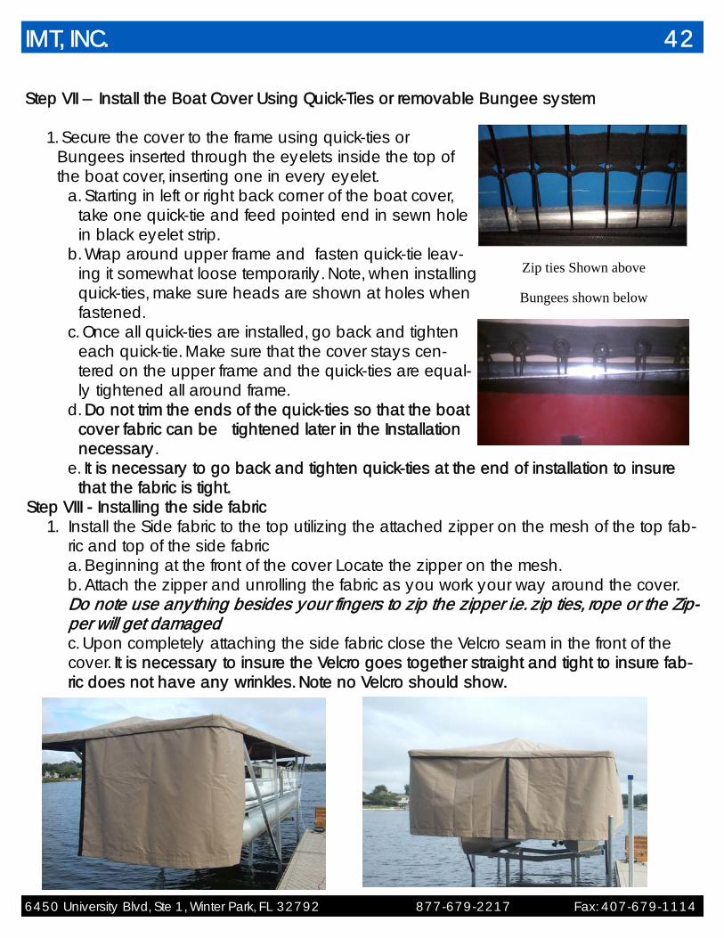
Step VII – Install the Boat Cover Using Quick-Ties or removable Bungee system
1. Secure the cover to the frame using quick-ties or Bungees inserted through the eyelets inside the top of the boat cover, inserting one in every eyelet.
a. Starting in left or right back corner of the boat cover, take one quick-tie and feed pointed end in sewn hole in black eyelet strip.
b. Wrap around upper frame and fasten quick-tie leav-ing it somewhat loose temporarily. Note, when installing quick-ties, make sure heads are shown at holes when fastened.
c. Once all quick-ties are installed, go back and tighten each quick-tie. Make sure that the cover stays cen-tered on the upper frame and the quick-ties are equal-ly tightened all around frame.
d. Do not trim the ends of the quick-ties so that the boat cover fabric can be tightened later in the Installation necessary.
e. It is necessary to go back and tighten quick-ties at the end of installation to insure that the fabric is tight.
Step VIII - Installing the side fabric 1. Install the Side fabric to the top utilizing the attached zipper on the mesh of the top fab-
ric and top of the side fabric a. Beginning at the front of the cover Locate the zipper on the mesh. b. Attach the zipper and unrolling the fabric as you work your way around the cover. Do note use anything besides your fingers to zip the zipper i.e. zip ties, rope or the Zip-per will get damaged c. Upon completely attaching the side fabric close the Velcro seam in the front of the cover. It is necessary to insure the Velcro goes together straight and tight to insure fab-ric does not have any wrinkles. Note no Velcro should show.
IMT, INC. 42
Zip ties Shown above
Bungees shown below

6450 University Blvd, Ste 1, Winter Park, FL 32792 877-679-2217 Fax: 407-679-1114
Step IX – Assembling the lower frame
1. To begin assembly of the lower frame, collect the parts marked with letters. The lower frame components are indicated by their letters and not numbers.
(Refer to labeling diagram) 2. Start by connecting the lower left and right frame assemblies as shown in the
Frame Labeling Diagram at the end of the installation instructions. a. Make sure to secure all connection with large tek screws.
3. You will next install the back lower frame assembly, a. Open a small portion of the Velcro in the lower pocket at rear left inside of boat
cover. b. Carefully slide the rear pipe into opening in lower pocket towards opposite side
of cover until it is completely resting in the Velcro opening pocket. Be careful as you feed the pipe through the Velcro opening pocket so you keep the sharp edges of the pipe from cutting into the fabric.
c. Rear pipe fittings should be carefully installed on the inside of the Velcro pocket opening.
4. Using the left lower frame assembly assembled earlier, locate the Velcro opening
pocket on the front left inside corner of cover and carefully slide the left lower frame assembly into the opening.
a. Push it towards the back of the cover until it comes in contact with the rear low-er frame assembly at fitting “A”.
b. Connect the left lower frame assembly to the back lower frame assembly where they meet and secure the connection point with a large tek screw.
5. Repeat this process for the re-
maining lower frame pipes. 6. Insert the lower frame nose piece
onto pipes and secure both connection points with large tek screws.
7. Finish by closing the Velcro pocket
to conceal the lower frame. (Refer to labeling diagram)
IMT, INC. 43

6450 University Blvd, Ste 1, Winter Park, FL 32792 877-679-2217 Fax: 407-679-1114
Step X – Installing the Fiberglass Rod Retraction System
1. Install the fiberglass rods, which are part of the retraction system by sliding the rods in the rows of the Velcro loops on the inside of the cover.
a. First, locate rubber connectors and fiberglass rods. b. Separate rods according to size and determine placement in cover. c. Starting with the side rods, slide it through the top row of loops on the side of
cover, starting in the middle and working your way back to the rear. d. Then insert rubber connectors on either side of the rod. Note that for straight
connections, you would use the shorter rod connectors, and for all turns or cor-ner connections, you would install large rod connectors.
i. Insert the rod one inch into the connector on either side leaving a gap in the connector to allow the rod circuit to flex.
e. Insert the rods accordingly into the rows of loops connecting them with rod connectors as instructed. Hint: leave the straight side connections for last, as any adjustments to the rods can be done if needed. When properly adjusted, the rods should not be able to move more than 1/2” in any direction with light pressure, but not to push fabric out (This could cause future damage to the fabric.)
f. If you need to extend a rod away from a connector, push only the end of the rubber connector when holding the fiberglass rod. This can be achieved by using a ¼” box end wrench slid over the rod up against the back of the rod connector as leverage.
IMT, INC. 44
6450 University Blvd, Ste 1, Winter Park, FL 32792 877-679-2217 Fax: 407-679-1114
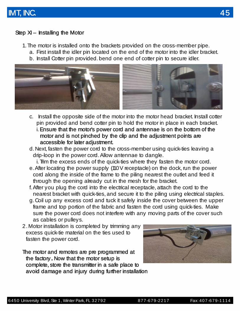
Step XI – Installing the Motor
1. The motor is installed onto the brackets provided on the cross-member pipe. a. First install the idler pin located on the end of the motor into the idler bracket. b. Install Cotter pin provided. bend one end of cotter pin to secure idler.
c. Install the opposite side of the motor into the motor head bracket. Install cotter pin provided and bend cotter pin to hold the motor in place in each bracket. i. Ensure that the motor’s power cord and antennae is on the bottom of the
motor and is not pinched by the clip and the adjustment points are accessible for later adjustment.
d. Next, fasten the power cord to the cross-member using quick-ties leaving a drip-loop in the power cord. Allow antennae to dangle.
i. Trim the excess ends of the quick-ties where they fasten the motor cord. e. After locating the power supply (110V receptacle) on the dock, run the power
cord along the inside of the frame to the piling nearest the outlet and feed it through the opening already cut in the mesh for the bracket.
f. After you plug the cord into the electrical receptacle, attach the cord to the nearest bracket with quick-ties, and secure it to the piling using electrical staples.
g. Coil up any excess cord and tuck it safely inside the cover between the upper frame and top portion of the fabric and fasten the cord using quick-ties. Make sure the power cord does not interfere with any moving parts of the cover such as cables or pulleys.
2. Motor installation is completed by trimming any excess quick-tie material on the ties used to fasten the power cord.
The motor and remotes are pre programmed at
the factory.. Now that the motor setup is complete, store the transmitter in a safe place to avoid damage and injury during further installation
IMT, INC. 45
6450 University Blvd, Ste 1, Winter Park, FL 32792 877-679-2217 Fax: 407-679-1114
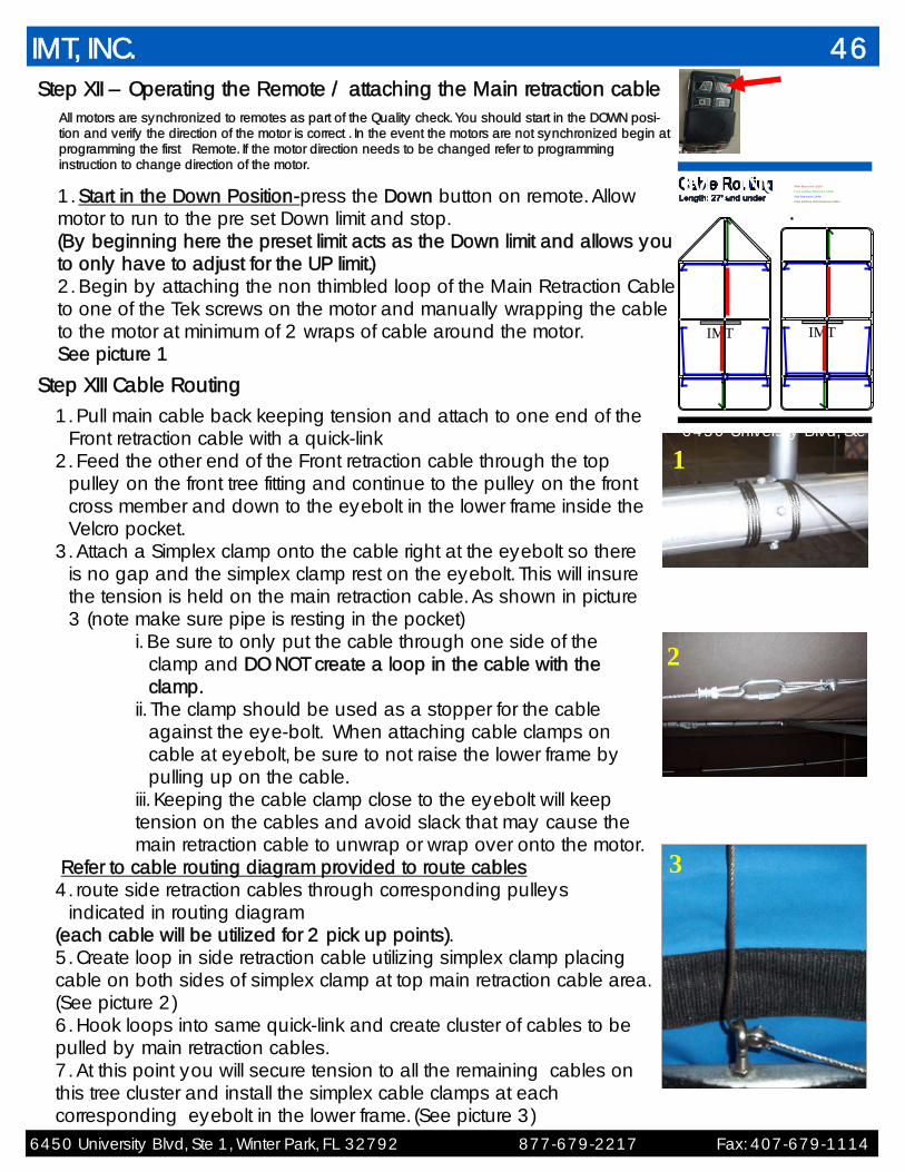
Step XII – Operating the Remote / attaching the Main retraction cable All motors are synchronized to remotes as part of the Quality check. You should start in the DOWN posi-tion and verify the direction of the motor is correct . In the event the motors are not synchronized begin at programming the first Remote. If the motor direction needs to be changed refer to programming instruction to change direction of the motor.
1. Start in the Down Position-press the Down button on remote. Allow motor to run to the pre set Down limit and stop. (By beginning here the preset limit acts as the Down limit and allows you to only have to adjust for the UP limit.) 2. Begin by attaching the non thimbled loop of the Main Retraction Cable to one of the Tek screws on the motor and manually wrapping the cable to the motor at minimum of 2 wraps of cable around the motor. See picture 1
1
3
1. Pull main cable back keeping tension and attach to one end of the Front retraction cable with a quick-link
2. Feed the other end of the Front retraction cable through the top pulley on the front tree fitting and continue to the pulley on the front cross member and down to the eyebolt in the lower frame inside the Velcro pocket.
3. Attach a Simplex clamp onto the cable right at the eyebolt so there is no gap and the simplex clamp rest on the eyebolt. This will insure the tension is held on the main retraction cable. As shown in picture 3 (note make sure pipe is resting in the pocket)
i. Be sure to only put the cable through one side of the clamp and DO NOT create a loop in the cable with the clamp.
ii. The clamp should be used as a stopper for the cable against the eye-bolt. When attaching cable clamps on cable at eyebolt, be sure to not raise the lower frame by pulling up on the cable.
iii. Keeping the cable clamp close to the eyebolt will keep tension on the cables and avoid slack that may cause the main retraction cable to unwrap or wrap over onto the motor.
Refer to cable routing diagram provided to route cables 4. route side retraction cables through corresponding pulleys
indicated in routing diagram (each cable will be utilized for 2 pick up points). 5. Create loop in side retraction cable utilizing simplex clamp placing cable on both sides of simplex clamp at top main retraction cable area. (See picture 2) 6. Hook loops into same quick-link and create cluster of cables to be pulled by main retraction cables. 7. At this point you will secure tension to all the remaining cables on this tree cluster and install the simplex cable clamps at each corresponding eyebolt in the lower frame. (See picture 3)
IMT, INC. 46
2
6450 University Blvd, Ste
IMT IMT
Main Retraction Cables
Front and Rear Retraction Cables
Side Retraction Cables
Front and Rear Side Retraction Cables
IMT, INC.
Step XIII Cable Routing

6450 University Blvd, Ste 1, Winter Park, FL 32792 877-679-2217 Fax: 407-679-1114
Refer to cable routing diagram provided. You should dou-ble check that you have the proper cable distance from the motor and cluster cable’s quick link to raise cover. Example 60” side height = 60” travel from quick-link to mo-tor tube- quick– link should not wrap on motor tube. Repeat cable Routing steps for the Rear tree and the rear main retraction cable Note all cables are color coded for ease of installation
9. The final step in the cable installation includes securing
the retraction cable to the fiberglass rods. The rod should be between the cable and the inside of the fabric
a. Install quick-ties at each point where the retraction cable intersects with fiberglass rods inside the cover.
b. You should form small quick tie loops that should be no smaller than ¾”. Keep in mind that quick-tie heads should not push against the fabric but point up.
c. Cut off the excess portion of each quick-tie to finish cable installation. If it is not installed correctly, the fabric will be cut into over time. If the quick-ties are not opened to ¾” the cable will not slide smoothly.
IMT, INC. 47
6450 University Blvd, Ste 1,
IMT IMT
Main Retraction Cables
Front and Rear Retraction Cables
Side Retraction Cables
Front and Rear Side Retraction
IMT, INC.
6450 University Blvd, Ste 1,
IMT
IMT
IMT, INC.
6450 University Blvd, Ste 1, Winter Park, FL 32792 877-679-2217 Fax: 407-679-1114
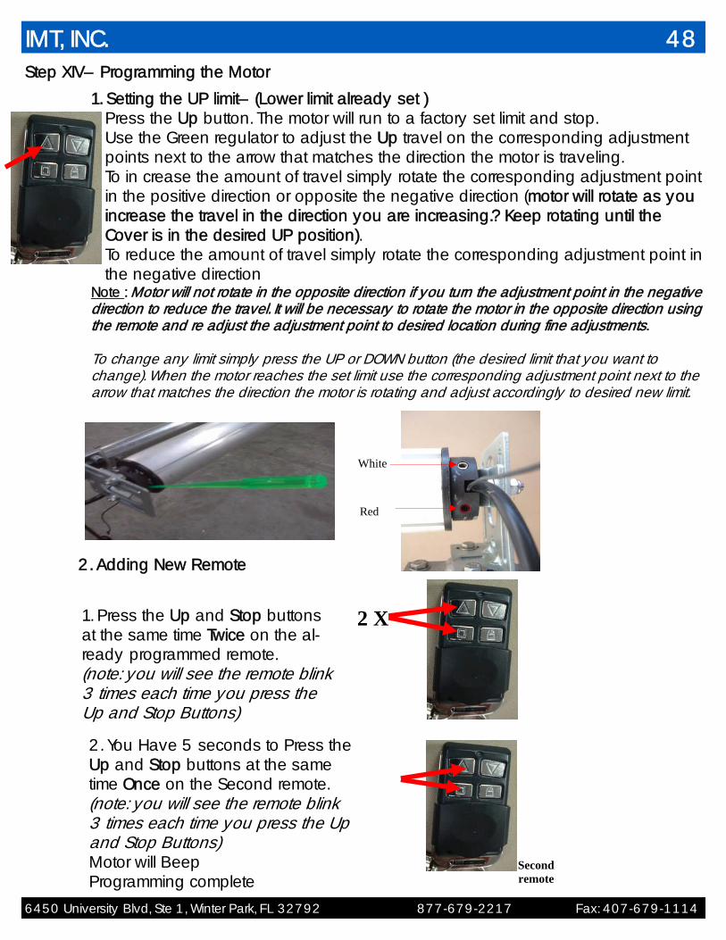
Step XIV– Programming the Motor
1. Setting the UP limit– (Lower limit already set ) Press the Up button. The motor will run to a factory set limit and stop. Use the Green regulator to adjust the Up travel on the corresponding adjustment points next to the arrow that matches the direction the motor is traveling. To in crease the amount of travel simply rotate the corresponding adjustment point in the positive direction or opposite the negative direction (motor will rotate as you increase the travel in the direction you are increasing.? Keep rotating until the Cover is in the desired UP position). To reduce the amount of travel simply rotate the corresponding adjustment point in the negative direction
Note : Motor will not rotate in the opposite direction if you turn the adjustment point in the negative direction to reduce the travel. It will be necessary to rotate the motor in the opposite direction using the remote and re adjust the adjustment point to desired location during fine adjustments. To change any limit simply press the UP or DOWN button (the desired limit that you want to change). When the motor reaches the set limit use the corresponding adjustment point next to the arrow that matches the direction the motor is rotating and adjust accordingly to desired new limit.
2. Adding New Remote
1. Press the Up and Stop buttons at the same time Twice on the al-ready programmed remote. (note: you will see the remote blink 3 times each time you press the Up and Stop Buttons)
Second remote
2. You Have 5 seconds to Press the Up and Stop buttons at the same time Once on the Second remote. (note: you will see the remote blink 3 times each time you press the Up and Stop Buttons) Motor will Beep Programming complete
2 X
White
Red
IMT, INC. 48
6450 University Blvd, Ste 1, Winter Park, FL 32792 877-679-2217 Fax: 407-679-1114
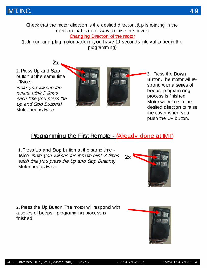
Check that the motor direction is the desired direction. (Up is rotating in the direction that is necessary to raise the cover.)
Changing Direction of the motor 1.Unplug and plug motor back in. (you have 10 seconds interval to begin the
programming)
2. Press Up and Stop button at the same time - Twice. (note: you will see the remote blink 3 times each time you press the Up and Stop Buttons) Motor beeps twice
2x
3. Press the Down Button. The motor will re-spond with a series of beeps programming process is finished Motor will rotate in the desired direction to raise the cover when you push the UP button.
Programming the First Remote - (Already done at IMT)
2x 1. Press Up and Stop button at the same time - Twice. (note: you will see the remote blink 3 times each time you press the Up and Stop Buttons) Motor beeps twice
2. Press the Up Button. The motor will respond with a series of beeps - programming process is finished
IMT, INC. 49
6450 University Blvd, Ste 1, Winter Park, FL 32792 877-679-2217 Fax: 407-679-1114
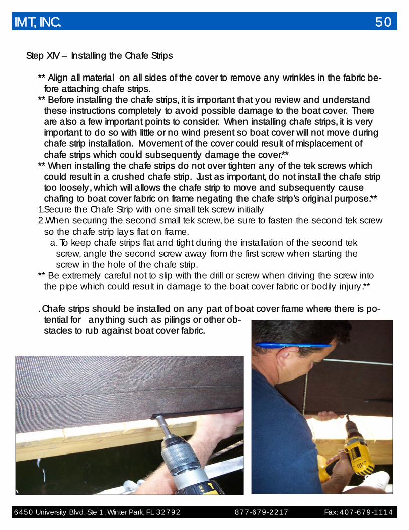
Step XIV – Installing the Chafe Strips
** Align all material on all sides of the cover to remove any wrinkles in the fabric be-fore attaching chafe strips.
** Before installing the chafe strips, it is important that you review and understand these instructions completely to avoid possible damage to the boat cover. There are also a few important points to consider. When installing chafe strips, it is very important to do so with little or no wind present so boat cover will not move during chafe strip installation. Movement of the cover could result of misplacement of chafe strips which could subsequently damage the cover.**
** When installing the chafe strips do not over tighten any of the tek screws which could result in a crushed chafe strip. Just as important, do not install the chafe strip too loosely, which will allows the chafe strip to move and subsequently cause chafing to boat cover fabric on frame negating the chafe strip’s original purpose.**
1.Secure the Chafe Strip with one small tek screw initially 2.When securing the second small tek screw, be sure to fasten the second tek screw
so the chafe strip lays flat on frame. a. To keep chafe strips flat and tight during the installation of the second tek
screw, angle the second screw away from the first screw when starting the screw in the hole of the chafe strip.
** Be extremely careful not to slip with the drill or screw when driving the screw into the pipe which could result in damage to the boat cover fabric or bodily injury.**
. Chafe strips should be installed on any part of boat cover frame where there is po-
tential for anything such as pilings or other ob-stacles to rub against boat cover fabric.
IMT, INC. 50

6450 University Blvd, Ste 1, Winter Park, FL 32792 877-679-2217 Fax: 407-679-1114
Step XV– Installing Cable covers on cable lifts Cable covers are designed to slide over the boat lift
cables and provide a simple chafe barrier with the fabric and the cable when the cover is in the down position and the boat is in the up position. Which is the majority of the time.
1.starting on the bottom of the cable begin installing cable covers over the cable.
2. bring cable covers to the highest position available either the pulley of the lift or the drive pipe, when the boat is in the desired Up position. This will act as a visual reference to stop the boat lift in the same position each time and ensure the cover will cover properly.
** It is important to note that too much up and down operation may cause the motor to overheat and shutdown. This is only temporary and the motor should be allowed to cool down completely before resuming normal operation of the cover.**
Take a final walk around to make sure everything looks good and works correctly. Make sure to double check for loose bolts, material that isn’t smooth,
possible rod adjustments, and general operation. Congratulations! The installation of the Touchless Boat Cover is now complete. Your customer can now enjoy years of trouble free protection for their boat. If you need additional installation information or support, please contact your IMT representative. Thanks again for you purchase!
IMT, INC. 51

6450 University Blvd, Ste 1, Winter Park, FL 32792 877-679-2217 Fax: 407-679-1114
IMT MOTOR IMT MOTOR
Main Retraction Cables
Front and Rear Retraction Cables
Side Retraction Cables
Front and Rear Side Retraction Cables
Pulleys
IMT, INC. 52
6450 University Blvd, Ste 1, Winter Park, FL 32792 877-679-2217 Fax: 407-679-1114
IMT MOTOR
IMT MOTOR
IMT, INC. 53

6450 University Blvd, Ste 1, Winter Park, FL 32792 877-679-2217 Fax: 407-679-1114
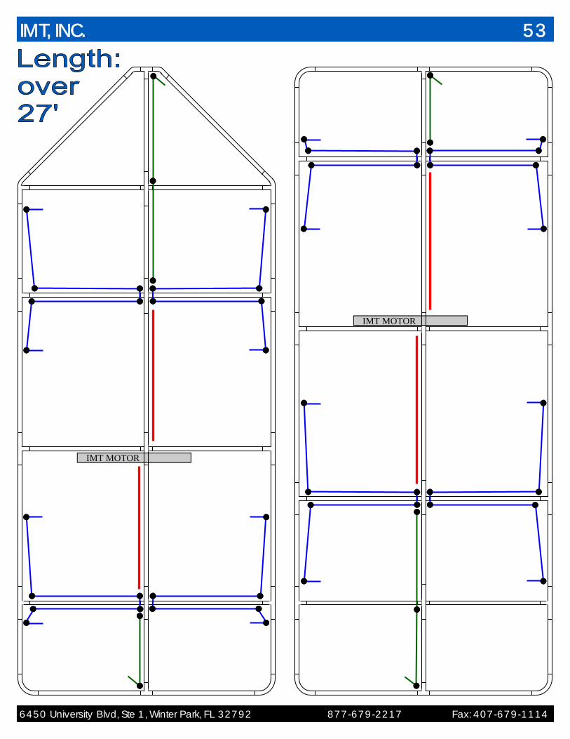
IMT MOTOR
IMT MOTOR
IMT, INC. 54
IMT, INC. 55
6450 University Blvd, Ste 1, Winter Park, FL 32792 877-679-2217 Fax: 407-679-1114
Covers up to 27’

Covers up to 27’
IMT, INC. 56
6450 University Blvd, Ste 1, Winter Park, FL 32792 877-679-2217 Fax: 407-679-1114
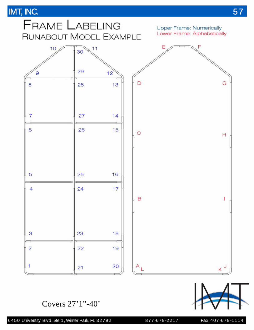
Covers 27’1”-40’
IMT, INC. 57
6450 University Blvd, Ste 1, Winter Park, FL 32792 877-679-2217 Fax: 407-679-1114
IMT, INC. 58
6450 University Blvd, Ste 1, Winter Park, FL 32792 877-679-2217 Fax: 407-679-1114
Covers 27’1”-40’