Embed Size (px)
Citation preview
INSTALLATION MANUAL
US Patent 8,992,089 B2

Thank you for purchasing the IMS Solution. Development of the IMS Solution spanned several years and took �ve generations of prototypes and tons of real life, practical application testing before being released to the worldwide market.
The IMS Solution became the �rst Patented IMS Retro�t product on the market on March 31, 2015 receiving US Patent 8,992,089 B2.
In these recently revised instructions you will learn the basics associated with �tment of the IMS Solution. The developers of the product have also added many “silver bullets” to the instructions based on frequently asked questions posed by installers.
Due to revisions to the instructions, all installers (even those who have installed dozens of the product previously) should review them, as some things have changed, and other items have been more clarified, as the product has evolved in the market place.
Jake Raby (Raby Engine Development) | Charles Navarro (LN Engineering)
Inventors and Developers of IMS Solution
INSTALLATION MANUAL

CHECK LIST
The following eleven step IMS Retrofit Pre- Qualification procedure was developed by Jake Raby at Flat 6 Innovations. During the initial development of the IMS Retrofit Procedure, and components, some items of concern were noted from the very beginning, and over the years these procedures have been updated to address these, thus increasing the effectiveness of the IMS Retrofit procedure.This procedure has been employed at Flat 6 Innovations since the very first IMS Retrofit was performed, and to date it has resulted in a 100% success rate for the Flat 6 Innovations Preventative Service program. Having performed the very first IMS Retrofit, and after performing more IMS Retrofits than any other facility, a perfect record has been maintained by Flat 6 Innovations by employing these procedures verbatim. This means that today, roughly 20% of all engines that are inspected will fail this pre- qualification, and will require repairs to be made prior to the IMS Retrofit being performed.The biggest mistake that can be made is assuming that every vehicle is healthy enough to have the IMS Retrofit performed. The second biggest mistake that can be made, is not taking the pre-qualification procedure seriously. Please pay attention to each and every engine, and realize that not every engine is a viable candidate for an IMS Retrofit.
STEPIMS RETROFIT & IMS SOLUTION
PRE-QUALIFICATION PROCEDURE
Perform controller interrogation (check for any Fault Codes, engine over-revs, Camshaft deviation #’s, etc…)
Remove Engine Oil Sump plate, inspect for debris. Removal of the sump plate is highly encouraged, as debris will lurk here that is not notable in the oil, or in the filter. Again, ANY debris of any sort is concerning, and must be investigated.
During all oil, sump and filter inspections, remember that the tiniest particles are just as concerning as larger pieces. This is because they are even more easily mixed into, and suspended from the engine oil, allowing the debris to circulate all throughout the engine with damaging effects.
Perform bore scope inspection of all cylinder bores. Watch closely for scoring and any signs of wear. Wear debris from failing / failed cylinders has been proven to be very damaging to all engine internals, including IMS Bearings.
With the transaxle removed, inspect the Rear Main Seal bore to ensure the engine does not have a factory defect known as “crankshaft sag”. If this exists oil leakage at the RMS will be a terminal condition that can’t ever be remedied.
Perform Crankcase Manometer test. Healthy engines, with healthy Air/ Oil Separators at sea level will test at 5” of water. (Use CR Tools Manometer for best results)
Drain engine oil and inspect how the oil looks while draining, inspect engine oil drain plug closely. Inspect for ANY debris. Again, any debris is concerning, and must be taken seriously. Engines can run perfectly, and exhibit no other symptoms of imminent failure, yet can be slowly dying due to debris laden oil.
Check over car complete, perform vehicle safety inspection, and listen to engine to determine overall condition. Inspect for any engine and/or gearbox oil and/or coolant leaks and document. Driving the car prior to the retrofit is recommended, as issues may be caught prior to the retrofit process.
Remove engine oil filter, cut open and inspect for ANY debris. Look closely at the bottom of the factory filter canister, where debris often is collected. If ANY debris is present, the retrofit process must be aborted; and the source of the debris must be identified. Action must be taken to address these issues prior to the retrofit process being carried out. Retrofitting the IMSB of ANY engine that has wear metals, or other debris in the oil, will lead to collateral damages that can destroy the retrofitted IMS Bearing, as well as all other internally lubricated engine components.
Once the IMS Flange is removed, inspect the original IMS Bearing for signs of failure. Also, check for signs that the engine may have already experienced an IMS Bearing failure, and may have had another bearing fitted. Engines that have IMS shaft assemblies that have been through a failure are always damaged, and it is very important that these shafts are not fitted with any IMS Retrofit.
Five (5) chain M96 engines are known for high camshaft deviation values due to abnormally high wear found on the timing chain adjuster wear pads. This can occur at low mileage points. Camshaft deviations found over 6 degrees must be addressed prior to performing the IMS Retrofit. Failure to do this may result in a loss of valve timing during the procedure, or a Check Engine Light illumination immediately following the IMS Retrofit. This will be due to camshaft deviations that are operating out of range.
NOTE: Any and all fault codes, and or symptoms of rough running, etc. must be addressed prior to any IMS Retrofit Procedure. It is imperative that ONLY healthy, good running engines be retrofitted.
NEVER, UNDER ANY CIRCUMSTANCE, IS IT PERMISSABLE TO REMOVE A FAILED OR FAILING IMS BEARING AND REPLACE IT WITH AN IMS RETROFIT PRODUCT.IMS RETROFIT COMPONENTS AND PROCEDURES WERE DESIGNED FOR PREVENTATIVE PURPOSES ONLY.

STEP
2STEP
1The procedure begins with a vehicle with the engine removed for better illustrative purposes.
Rotate engine clockwise to locate cylinder #1 TDC
You do not have to remove the engine to install the IMS Solution. The process can be accomplished by only removing the transaxle, clutch assembly, and flywheel.
While cylinder 1 TDC and Cylinder 4 TDC have the same crankshaft position, the IMS Retrofit process can be carried out at cylinder 1, or cylinder 4 TDC without issues. This is due to the relaxed state of the valve train that is a constant between these two crankshaft positions.
TIP NOTE
INSTALLATION MANUAL PAGE 1

STEP
4STEP
3Lock engine in TDC position using crankshaft locking pin supplied with IMS pro tool kit.
Working at right side cylinder head, remove lower camshaft bore plug using a large pick. Remove and discard these bore plugs, and do not attempt to reuse them.
Right side determined when facing flywheel
NOTE
INSTALLATION MANUAL PAGE 2

STEP
6STEP
5Lock right side camshaft in place using IMS pro tool kit camshaft timing jig.
Remember to mark the original location of each timing chain tensioner for reinstallation, and be prepared to catch any dripping oil in a rag.
If jig does not fit into camshaft easily, the engine may be out 180°. Remove crankshaft locking pin and rotate engine one full rotation and try to install camshaft jig again
TIP
Some installers prefer to lock camshafts on BOTH banks of the engine. This is a practice that is not required, and is a matter of personal preference. With the crankshaft, and one bank of camshafts locked, all timing chains will be held tightly in the proper position for a successful IMS Retrofit procedure.
NOTE
INSTALLATION MANUAL PAGE 3

STEP
8STEP
7Working at left side cylinder head, remove timing chain tensioner.
Working at right side cylinder head, remove timing chain tensioner.
Be prepared to catch any dripping oil with a rag.
NOTE
INSTALLATION MANUAL PAGE 4
Right side determined when facing flywheel
NOTE
Right side determined when facing flywheel
NOTE

STEP
10STEP
9Working at flywheel side, remove IMS chain tensioner.
The next part of the procedure is going to cut a notch in the crank case for the pressurized oil line that feeds the IMS Solution.
There are a few different methods and many tools that you can use to create the notch in the crank case. The most important thing is to work slowly and do not remove too much material since the pieces cut off the crank case can not be replaced.
NOTE
INSTALLATION MANUAL PAGE 5
Be prepared to catch any dripping oil with a rag.
NOTE
Right side determined when facing flywheel
NOTE

STEP
12STEP
11This procedure is showing a drill and hand tools to create the notch in the crank case.
Using the IMS Solution flange as a guide, mark the center of the crank case using an awl.
INSTALLATION MANUAL PAGE 6

STEP
14STEP
13Using a sharp punch, lightly tap it with a rubber hammer to create a pilot mark for your drill bit.
Using a 3mm (1/8 in) drillbit, drill a pilot hole in the crank case.
INSTALLATION MANUAL PAGE 7

STEP
16STEP
15Next, using a 10mm (3/8 in) drillbit, drill the final hole in the crank case.
Next, using a handsaw, cut two straight lines into drilled holes to remove outer piece of crank case.
Once the hole is drilled, clean the metal shavings from crank case.
NOTE
INSTALLATION MANUAL PAGE 8

STEP
18STEP
17Once outer piece of crankcase is cut away, use a flat file and open up the hole until it is large enough to fit oil fitting.
Using the IMS Solutions oil fitting as a guide, check that there is ample room on each side of filled opening of crankcase.
File hole to 20mm ( 13/16in). Be sure to remove equal amounts of the opening. This will ensure a proper fit of the IMS Solution oil fitting.
NOTE
INSTALLATION MANUAL PAGE 9
STEP
20STEP
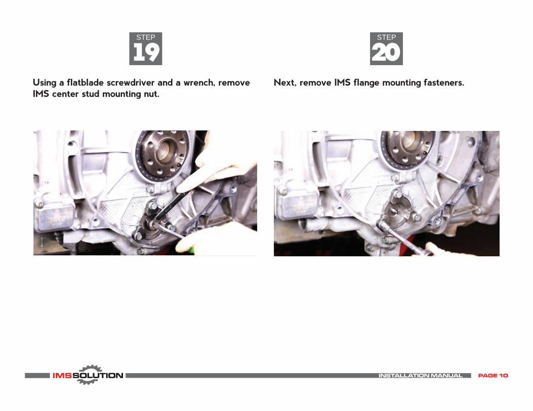
19Using a flatblade screwdriver and a wrench, remove IMS center stud mounting nut.
Next, remove IMS flange mounting fasteners.
INSTALLATION MANUAL PAGE 10

STEP
22STEP
21Using two flatblade screwdrivers, gently and evenly lever off the IMS bearing flange, then remove from engine.
Using a pair of snap ring pliers, remove IMS bearing snap ring.
Placing your finger or a flatblade screwdriver in the center of the snap ring when removing it, will prevent it from falling into the crankcase.
TIP
INSTALLATION MANUAL PAGE 11
IMPORTANT! The original factory snap ring must be saved for re-installation later.
NOTE
Dual row bearings do not have an external snap ring.
NOTE
STEP
24STEP
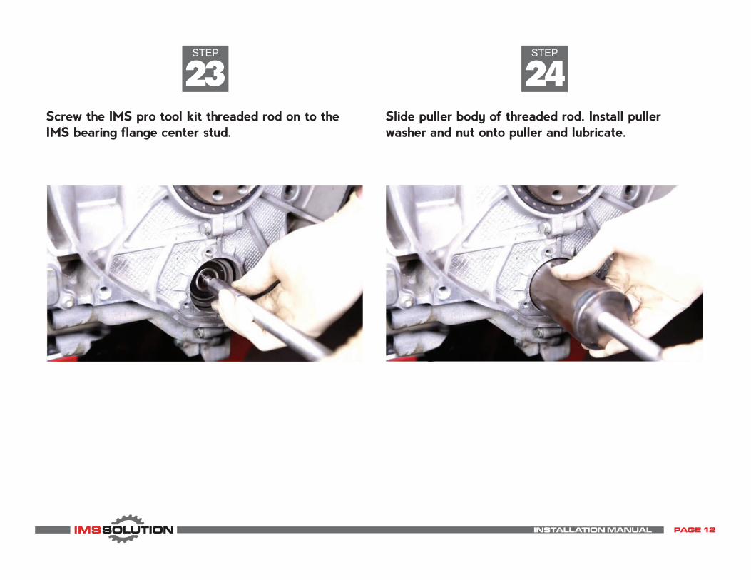
23Screw the IMS pro tool kit threaded rod on to the IMS bearing flange center stud.
Slide puller body of threaded rod. Install puller washer and nut onto puller and lubricate.
INSTALLATION MANUAL PAGE 12

STEP
26STEP
25Using IMS Pro Tool Kit puller, extract bearing from intermediate shaft.
Once clean, install intermediate shaft plug. Place plug into intermediate shaft...
Watch for an oil release when the IMS Bearing is extracted.
Hold threaded rod still while tightening nut on puller to extract bearing from intermediate shaft. Once bearing is extracted, thoroughly clean the inside of the intermediate shaft using a lint-free cloth.
TIP
NOTE
If using an 06-08 adapter bushing with your IMS Solution, please use the provided IMS plug from the 06-08 adapter kit.Plug must be installled prior to addapter bushing!
NOTE
INSTALLATION MANUAL PAGE 13

Plug installation tool is part of the IMS Supplemental Tool Kit
NOTE
STEP
28STEP
27...then using IMS plug installation tool, drive plug into intermediate shaft until the tool bottoms out. Ensure the plug fits the bore squarely, and tightly.
IMS plug installation tool is designed with collar to set plug to appropriate depth.
INSTALLATION MANUAL PAGE 14

STEP
30STEP
29Next, install the IMS Solution bearing for installation into the intermediate shaft. Place IMS solution bearing onto stud. Then take the bearing installer from the IMS pro tool kit and place it onto bearing.
Using supplied assembly lubes; lubricate the outside IMS Solution bearing before installing. Align IMS solution bearing with intermediate shaft.
Secure into place using a IMS flange nut. Do not over tighten. Finger tighten ONLY.
NOTE
Some drivers will not allow fitting the 12-pt nut. Fitting of nut not necessary.
NOTE
INSTALLATION MANUAL PAGE 15
STEP
32STEP
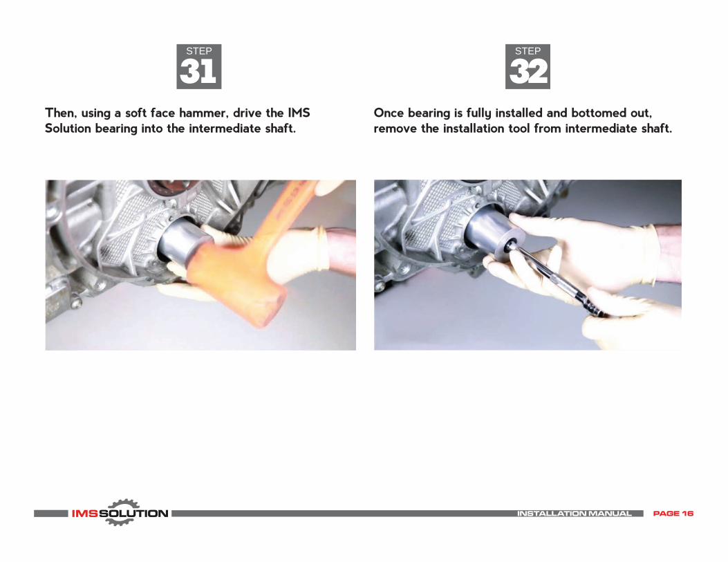
31Then, using a soft face hammer, drive the IMS Solution bearing into the intermediate shaft.
Once bearing is fully installed and bottomed out, remove the installation tool from intermediate shaft.
INSTALLATION MANUAL PAGE 16
STEP
34STEP
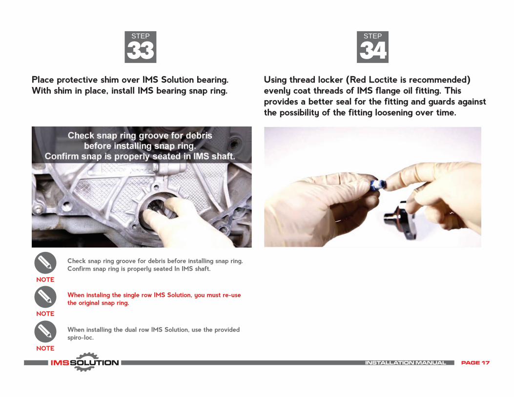
33Place protective shim over IMS Solution bearing. With shim in place, install IMS bearing snap ring.
Using thread locker (Red Loctite is recommended) evenly coat threads of IMS flange oil fitting. This provides a better seal for the fitting and guards against the possibility of the fitting loosening over time.
Check snap ring groove for debris before installing snap ring. Confirm snap ring is properly seated In IMS shaft.
NOTE
When installing the dual row IMS Solution, use the provided spiro-loc.
NOTE
When instaling the single row IMS Solution, you must re-use the original snap ring.
NOTE
INSTALLATION MANUAL PAGE 17
STEP
36STEP
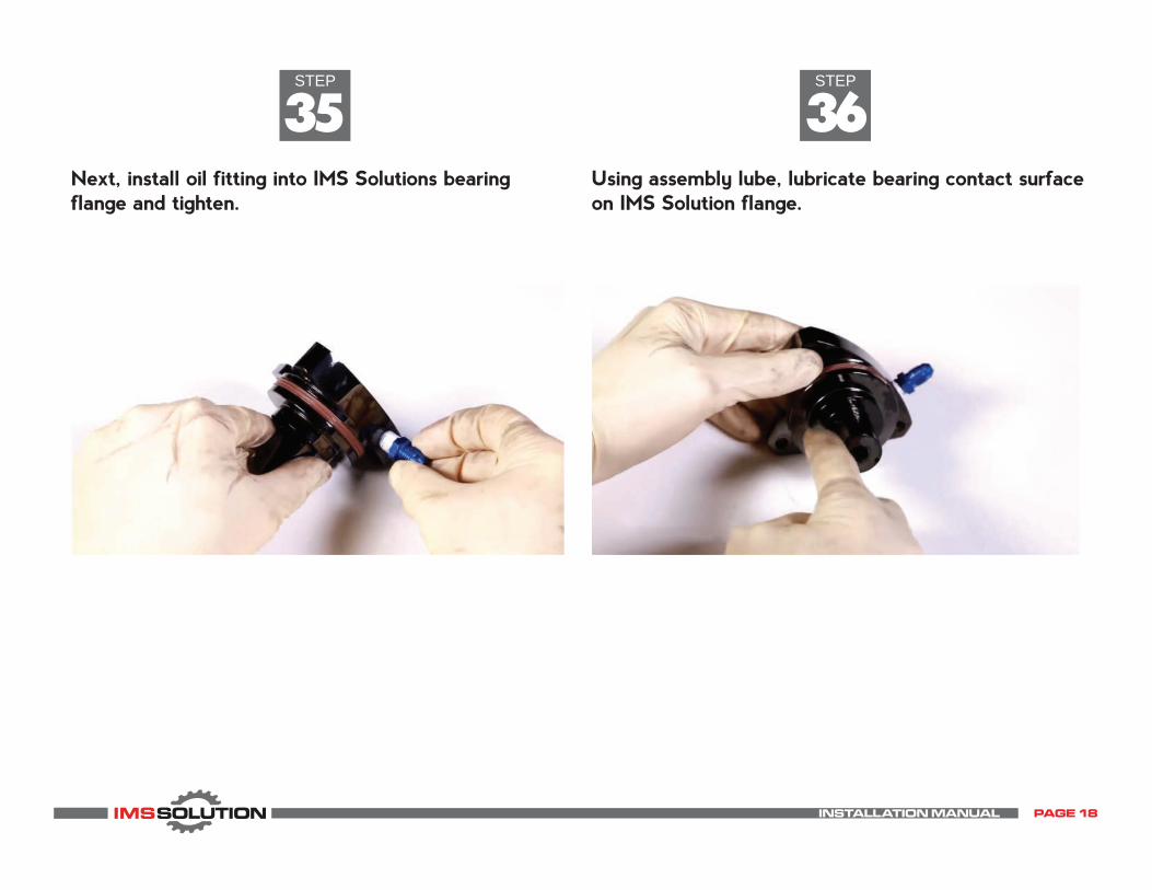
35Next, install oil fitting into IMS Solutions bearing flange and tighten.
Using assembly lube, lubricate bearing contact surface on IMS Solution flange.
INSTALLATION MANUAL PAGE 18

STEP
38STEP
37Using assembly lube, lubricate IMS Solution bearing and install IMS solution flange into bearing by hand. Then using a soft face hammer, lightly tap the IMS Solution flange until it is flush with crank case.
During assembly, ensure the o-ring inside the IMS Solution flange and the seal on the outer diameterof the IMS Solution flange are not cut, or pinched.
Lubricate IMS Solution flange O ring using supplied assembly lube.
INSTALLATION MANUAL PAGE 19

STEP
40STEP
39Once IMS Solution flange is flush with crankcase, install IMS Solution flange fasteners finger tight.
Coat IMS Solution flange fastener with supplied thread sealer.
INSTALLATION MANUAL PAGE 20

STEP
42STEP
41Once center stud nut has been a installed finger tight, torque IMS flange bolts. Once the IMS flange bolts have been torqued, torque the IMS flange center nut.
Using a wrench and a flat blade screwdriver, install IMS flange center stud nut. Do not torque nut yet.
IMS flange fastener torque: 10Nm(7ft-lb)
NOTE
Center IMS flange nut torque must be at least 12 ft/ lb,but not to exceed 20 ft/lb
NOTE
INSTALLATION MANUAL PAGE 21

STEP
44STEP
43Once the o-ring has been lubricated with clean engine oil, install IMS Solution oil filter adapter into engine. Hand tighten oil filter adapter. Then, torque oil filter adapter.
Lubricate the o-ring on IMS Solution’s spin-on oil fillter adapter using clean engine oil.
Spin-on Oil Filter Adapter must be installed using SPOFA spanner wrench, which is part of the IMS Supplemental Tool Kit.
Spin-on oil filter torque: 24Nm(18ft-lb)
NOTE
INSTALLATION MANUAL PAGE 22
STEP
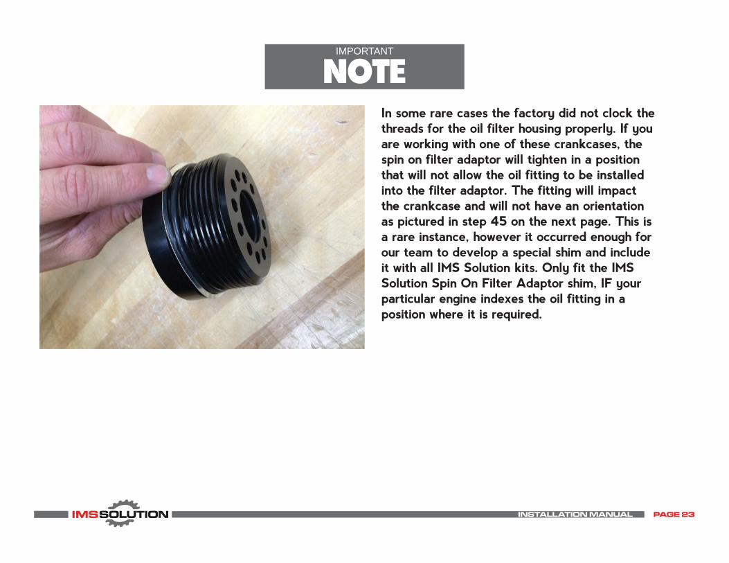
In some rare cases the factory did not clock the threads for the oil filter housing properly. If you are working with one of these crankcases, the spin on filter adaptor will tighten in a position that will not allow the oil fitting to be installed into the filter adaptor. The fitting will impact the crankcase and will not have an orientation as pictured in step 45 on the next page. This is a rare instance, however it occurred enough for our team to develop a special shim and include it with all IMS Solution kits. Only fit the IMS Solution Spin On Filter Adaptor shim, IF your particular engine indexes the oil fitting in a position where it is required.
STEPIMPORTANT
NOTE
INSTALLATION MANUAL PAGE 23

STEP
46STEP
45In the next steps, you will fit the IMS Solution oil feed hose to the Spin On Filter Adaptor, and the IMS Solution Flange. The completed hose assembly should appear like the photo below.
Using supplied thread sealer, coat threads on oil filter adapter oil fitting (black fitting with o-ring). Install fitting into IMS Solution oil filter adapter and tighten.
INSTALLATION MANUAL PAGE 24

STEP
48STEP
47Install supplied oil filter onto IMS Solution oil filter adapter.
Install steel braided hose onto IMS flange finger tight. Then, install onto IMS Solution spin-on oil filter adapter finger tight. Next, tighten both ends of steel hose fittings. Thread sealant is optional, but recommended on these surfaces.
Thoroughly clean the inside of steel braided hose before installing.
NOTE
Pre-fill oil filter with clean engine oil before installing.
NOTE
INSTALLATION MANUAL PAGE 25

STEPINSTALLATION
COMPLETEInstallation is now complete. Once the engine is reassembled and other components have been reinstalled, start engine and run until oil light is no longer illuminated.
IT IS IMPORTANT TO READ AND UNDERSTAND CRITICAL POST PROCEDURE NOTES.PLEASE SEE NEXT PAGE.
IMS Solution is designed for 5,000 miles oil change intervals. Joe Gibbs Racing DRIVEN DT40 motor oil is recommended.NOTE
Quickly starting and shutting off the engine 4-5 times will help to achieve oil pressure faster. Repeat this step two additional times. Check and top up engine oil as needed.
TIP
Do not pull the DME or Fuel Pump relays in hope of achieving oil pressure without the engine starting, the M96 engine will seldom achieve oil pressure in this manner.
TIP
INSTALLATION MANUAL PAGE 26

STEPCRITICAL
POST PROCEDURE NOTESNEVER, UNDER ANY CIRCUMSTANCE, RETROFIT AN ENGINE THAT HAS SUFFERED AN IMS BEARING FAILURE!
ALWAYS use the eleven step IMS Retrofit Pre- Procedure checklist when qualifying any vehicle for an IMS Retrofit.
ALWAYS perform an oil service when carrying out any IMS Retrofit procedure. Never reuse old oil, no matter how clean you believe it may be.
When sealing up crankcase sump plates, following the pre- procedure inspection, use a nominal amount of sealant. Liberal amounts of sealant will mix into the oil and find their way to the oil pick up tube, blocking oil flow, and killing the engine.
After initial start up of the engine that has been retrofitted, check all flange surfaces, and oil lines for signs of oil leakage.
With the vehicle back on the ground completely, check the IMS Solution oil feed line for contact with all its surroundings, especially the rear sway bar.
Extreme caution must be given to vehicles with aftermarket rear sway bars. These are larger in outside diameter and therefore are more probable to have conflicts with the IMS Solution oil feed line.
Use common sense, take your time, and pay attention! You can’t rush success, but you can rush failure!
Ensure the proper registration documents, to include photos; oil samples and registration forms are filed with IMS Solution LLC.
IMS Solution LLC strongly recommends using a magnetic oil drain plug in all IMS Solution / Retrofit equipped engines. Visit plug.LNengineering.com for more info.
POST PROCEDURE NOTES

The only Intermediate Shaft Bearing solution protected by US Patent.