Embed Size (px)
Citation preview
IMSA GT Spec Scrutineering System
Manual
V1.3.5 3/8/2017
Table of Contents
2 / 39 IMSA Spec GT Scrutineering Logger Bosch Motorsport
Table of Contents
Manual ................................................................................................................................................................................... 1
Table of Contents ................................................................................................................................................................. 2
1 Scope ................................................................................................................................................................................. 3
2 Contact .............................................................................................................................................................................. 4
2.1 Sales ................................................................................................................................................................................................................. 4 2.1.1 Track Sales ........................................................................................................................................... 4
3 Components ..................................................................................................................................................................... 5
3.1 Electronic Hardware .................................................................................................................................................................................. 5 3.1.1 C60 ...................................................................................................................................................... 5
3.1.2 IMU – MM5.10 .................................................................................................................................... 6
3.1.3 LT2 Sport ............................................................................................................................................. 7
3.1.4 GPS ...................................................................................................................................................... 7
3.1.5 X2 Transponder ................................................................................................................................... 8
3.2 Sensors ........................................................................................................................................................................................................... 9 3.2.1 1 Bar Pressure ................................................................................................................................... 10
3.2.2 3.5 Bar Boost Pressure ...................................................................................................................... 11
3.2.3 Temp Sensor – M12 .......................................................................................................................... 12
3.2.4 Temp Sensor – M6 ............................................................................................................................ 13
3.2.5 LSU 4.9 Lambda Sensor ..................................................................................................................... 14
3.3 Sensor Declaration Form ....................................................................................................................................................................... 14
4 System Architecture ..................................................................................................................................................... 15
4.1 Team CAN (C60 CAN #1) ...................................................................................................................................................................... 15
4.2 Scrutineering CAN (C60 CAN #2)....................................................................................................................................................... 15
4.3 Power Supply ............................................................................................................................................................................................. 16
4.4 USB ................................................................................................................................................................................................................. 16
5 Loom Certification ........................................................................................................................................................ 17
6 CAN Specification ......................................................................................................................................................... 17
6.1 Team Transmitted Channels ................................................................................................................................................................ 18
6.2 Team Received Channels ....................................................................................................................................................................... 21
6.3 DBC file ......................................................................................................................................................................................................... 23
7 Wiring Diagram ............................................................................................................................................................. 24
8 Appendix ........................................................................................................................................................................ 25
8.1 C60 ................................................................................................................................................................................................................. 26
8.2 IMU ................................................................................................................................................................................................................. 27
8.3 LT2 Sport ...................................................................................................................................................................................................... 28
8.4 GPS ................................................................................................................................................................................................................. 29
8.5 1 Bar Pressure ............................................................................................................................................................................................ 30
8.6 3.5 Bar Pressure ......................................................................................................................................................................................... 31
8.7 Temperature M12 ..................................................................................................................................................................................... 32
8.8 Temperature M6 ....................................................................................................................................................................................... 33
Bosch Motorsport IMSA Spec GT Scrutineering Logger 3 / 39
8.9 Lambda ......................................................................................................................................................................................................... 34
9 Order Form ..................................................................................................................................................................... 35
10 Declaration Form ........................................................................................................................................................... 36
11 Revisions ......................................................................................................................................................................... 37
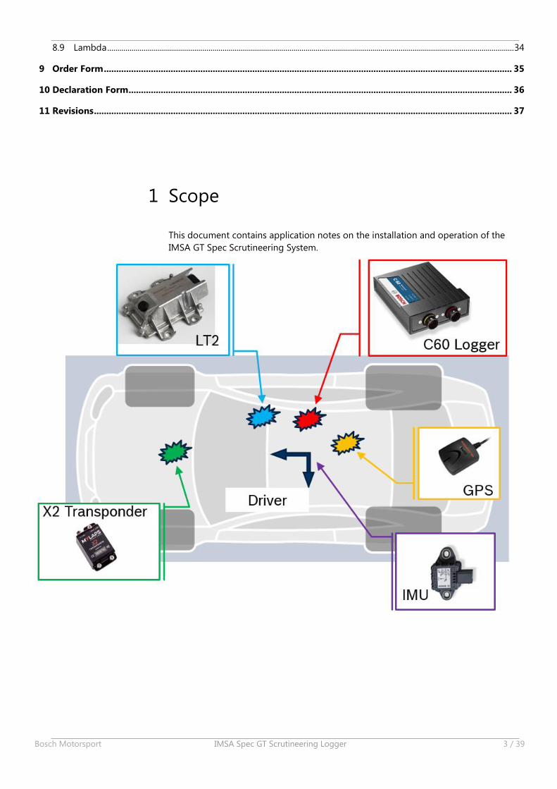
1 Scope
This document contains application notes on the installation and operation of the
IMSA GT Spec Scrutineering System.
2 | Contact
4 / 39 IMSA Spec GT Scrutineering Logger Bosch Motorsport
2 Contact For technical information please contact:
Tel: +1-248-221-0418
For sales information please contact an approved dealer:
Mech-Tronic Owner / Contact: Bill Roth Address: 323 Cooldige Drive Centerport, NY 11721 Phone : 631-423-0523 Fax : 631-423-7769 Email : [email protected]
Sakata Motorsports Electronics, Inc. Owner / Contact: Brian Sakata Address: 1241 N. Patt ST. Anaheim, CA 92801 Phone : 714-446-9473 Fax : 714-446-9247 Email : [email protected]
Creative Motorsport Solutions Owner / Contact: Colin Harmer Address: 222 Oakridge Blvd Suite 110 Daytona Beach, FL 32118 Phone : 813-482-2178 Email : [email protected]
2.1 Sales Sales can be performed through the above dealers, OEM customers may purchase
directly through Bosch Motorsport North America.
2.1.1 Track Sales
Customers requiring spare parts purchased and delivered at the racetrack are
subject to a 10% service fee.

3 | Components
Bosch Motorsport IMSA Spec GT Scrutineering Logger 5 / 39
3 Components
3.1 Electronic Hardware Component List:
Part Number Mating Connector Name Description
F02U.V0U.207-01ASDD612-41SN
ASDD612-41SAC60 GT Scrutineering Logger
F02U.V01.511-02 F02U.B00.435-01 IMU 5 axis IMU
1271.032.390 IMU mounting plate
F02U.V0U.152-01 F02U.V0U.150-01 LT2 Sport 2 channel lambda controller
F02U.V0U.203-01 ASU603-03SN GPS 10 Hz GPS unit
F02U.V0U.204-01 ASL106-05SA 1 Bar Pressure Air pressure sensor
F02U.V0U.205-01 ASL106-05SB 3.5 Bar Pressure Boost pressure sensor
F02U.V0U.206-01 ASL106-05SN Temperature Sensor M12 Air temperature sensor
F02U.V02.356-01 ASL106-05SN Temperature Sensor M6 Air temperature sensor
0258.988.001 D261.205.356-01 LSU 4.9 Lambda Sensor
ASU603-05SN X2 Transponder* Timing Transponder
ASL106-05SB ACO Oil Level * Catch tank oil level sensor
Max current consumption for all devices: 13 amps.
Nominal current consumption for all devices: 6 amps.
*See IMSA Tech Bulletin IWSC #16-03 for X2 Transponder and the ACO Oil Level
sensor availability.
3.1.1 C60
Functional Description: Logger for IMSA GT Spec Scrutineering System
Mounting Note:
This device must be fitted in the cockpit on the passenger side floor in an
easily accessible IMSA approved location.
This device must be mounted away from heat sources. Note maximum
temperature range below.
This device should be mounted so that the status LED’s on top of the
device can be easily seen.
Part Number: F02U.V0U.207-01
Temperature Range: -20 to 65 °C
Maximum Current Consumption: 2 amps
Pinout: See “Wiring Diagram” for C60 pinout
3 | Components
6 / 39 IMSA Spec GT Scrutineering Logger Bosch Motorsport
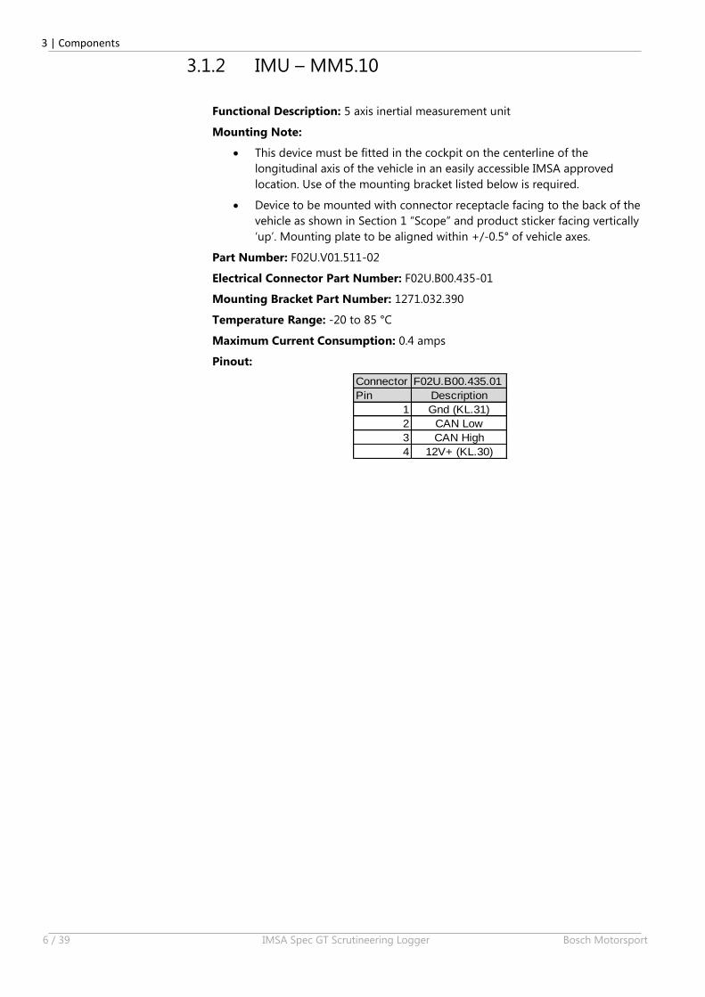
3.1.2 IMU – MM5.10
Functional Description: 5 axis inertial measurement unit
Mounting Note:
This device must be fitted in the cockpit on the centerline of the
longitudinal axis of the vehicle in an easily accessible IMSA approved
location. Use of the mounting bracket listed below is required.
Device to be mounted with connector receptacle facing to the back of the
vehicle as shown in Section 1 “Scope” and product sticker facing vertically
‘up’. Mounting plate to be aligned within +/-0.5° of vehicle axes.
Part Number: F02U.V01.511-02
Electrical Connector Part Number: F02U.B00.435-01
Mounting Bracket Part Number: 1271.032.390
Temperature Range: -20 to 85 °C
Maximum Current Consumption: 0.4 amps
Pinout:
Connector F02U.B00.435.01
Pin Description
1 Gnd (KL.31)
2 CAN Low
3 CAN High
4 12V+ (KL.30)
3 | Components
Bosch Motorsport IMSA Spec GT Scrutineering Logger 7 / 39
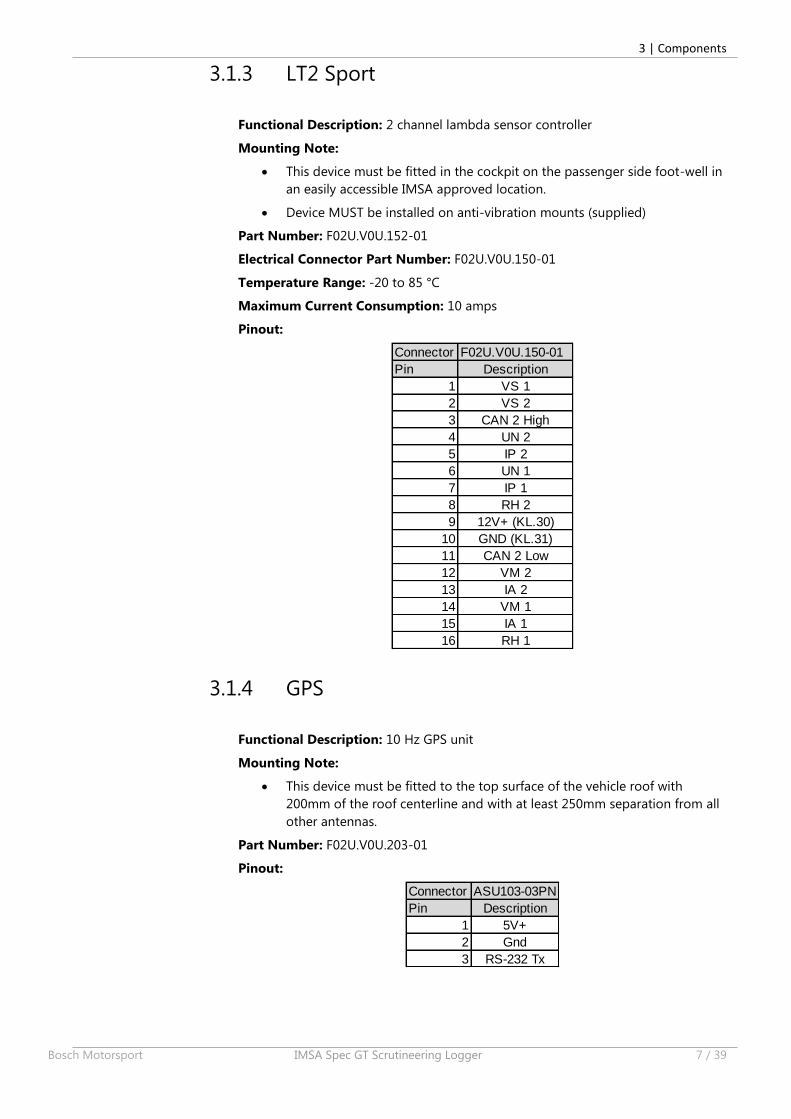
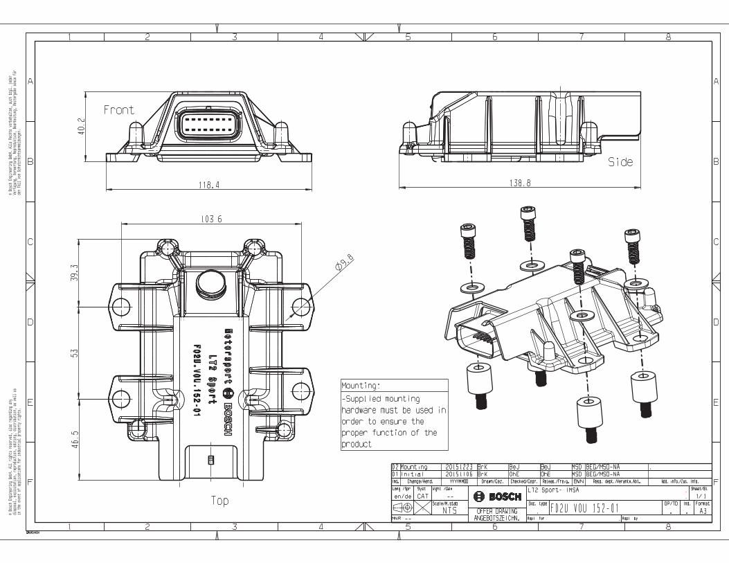
3.1.3 LT2 Sport
Functional Description: 2 channel lambda sensor controller
Mounting Note:
This device must be fitted in the cockpit on the passenger side foot-well in
an easily accessible IMSA approved location.
Device MUST be installed on anti-vibration mounts (supplied)
Part Number: F02U.V0U.152-01
Electrical Connector Part Number: F02U.V0U.150-01
Temperature Range: -20 to 85 °C
Maximum Current Consumption: 10 amps
Pinout:
Connector F02U.V0U.150-01
Pin Description
1 VS 1
2 VS 2
3 CAN 2 High
4 UN 2
5 IP 2
6 UN 1
7 IP 1
8 RH 2
9 12V+ (KL.30)
10 GND (KL.31)
11 CAN 2 Low
12 VM 2
13 IA 2
14 VM 1
15 IA 1
16 RH 1
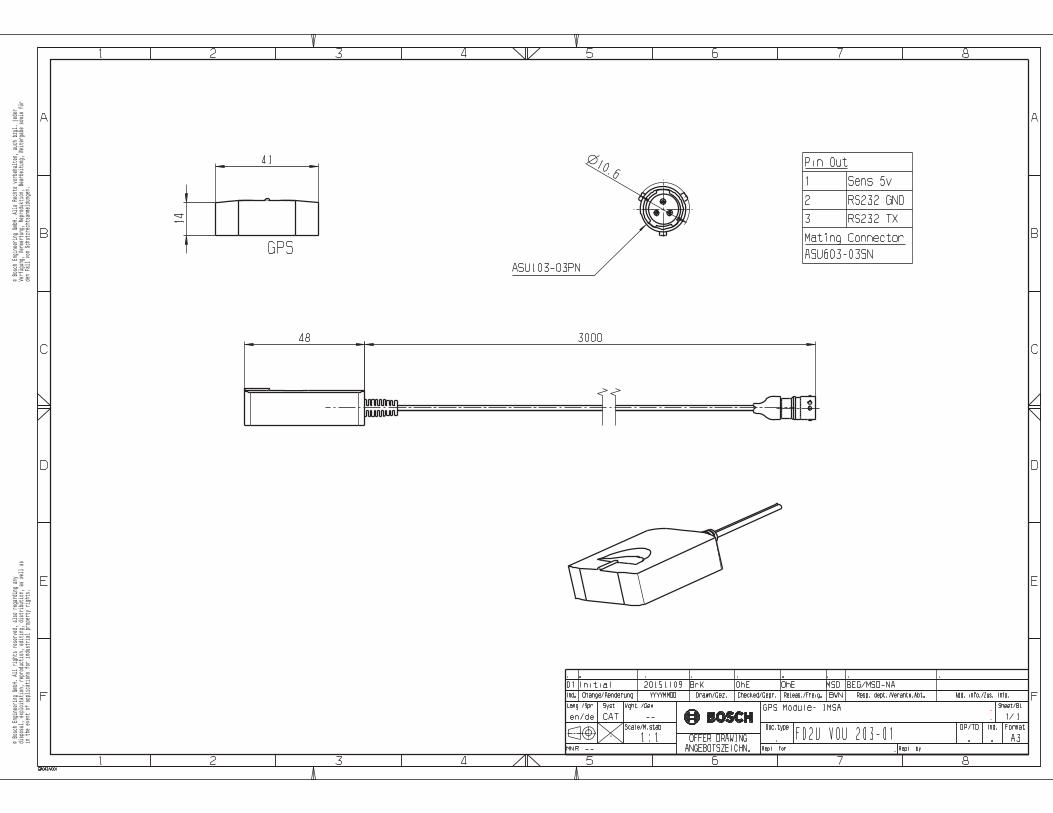
3.1.4 GPS
Functional Description: 10 Hz GPS unit
Mounting Note:
This device must be fitted to the top surface of the vehicle roof with
200mm of the roof centerline and with at least 250mm separation from all
other antennas.
Part Number: F02U.V0U.203-01
Pinout:
Connector ASU103-03PN
Pin Description
1 5V+
2 Gnd
3 RS-232 Tx
3 | Components
8 / 39 IMSA Spec GT Scrutineering Logger Bosch Motorsport
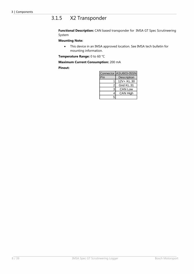
3.1.5 X2 Transponder
Functional Description: CAN based transponder for IMSA GT Spec Scrutineering
System
Mounting Note:
This device in an IMSA approved location. See IMSA tech bulletin for
mounting information.
Temperature Range: 0 to 60 °C
Maximum Current Consumption: 200 mA
Pinout:
Connector ASU603-05SN
Pin Description
1 12V+ KL.30
2 Gnd KL.31
3 CAN Low
4 CAN High
5
3 | Components
Bosch Motorsport IMSA Spec GT Scrutineering Logger 9 / 39
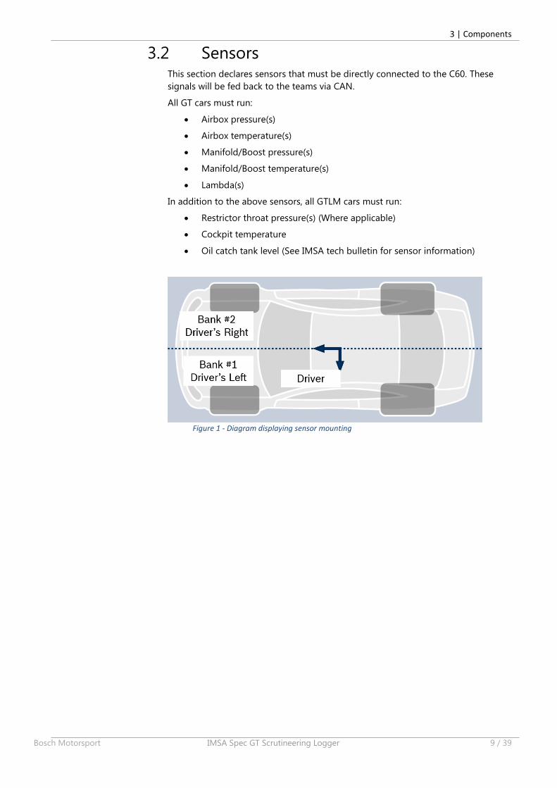
3.2 Sensors This section declares sensors that must be directly connected to the C60. These
signals will be fed back to the teams via CAN.
All GT cars must run:
Airbox pressure(s)
Airbox temperature(s)
Manifold/Boost pressure(s)
Manifold/Boost temperature(s)
Lambda(s)
In addition to the above sensors, all GTLM cars must run:
Restrictor throat pressure(s) (Where applicable)
Cockpit temperature
Oil catch tank level (See IMSA tech bulletin for sensor information)
Figure 1 - Diagram displaying sensor mounting
3 | Components
10 / 39 IMSA Spec GT Scrutineering Logger Bosch Motorsport
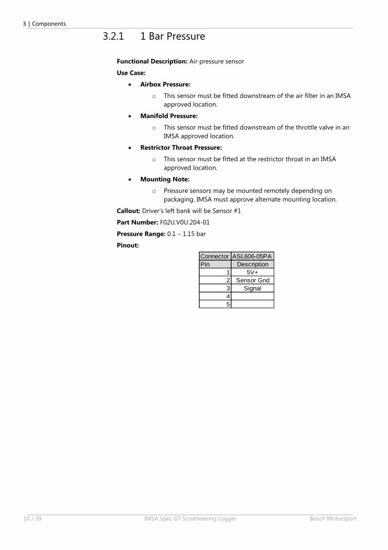
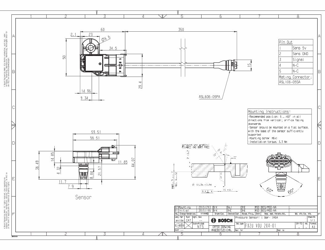
3.2.1 1 Bar Pressure
Functional Description: Air pressure sensor
Use Case:
Airbox Pressure:
o This sensor must be fitted downstream of the air filter in an IMSA
approved location.
Manifold Pressure:
o This sensor must be fitted downstream of the throttle valve in an
IMSA approved location.
Restrictor Throat Pressure:
o This sensor must be fitted at the restrictor throat in an IMSA
approved location.
Mounting Note:
o Pressure sensors may be mounted remotely depending on
packaging. IMSA must approve alternate mounting location.
Callout: Driver’s left bank will be Sensor #1
Part Number: F02U.V0U.204-01
Pressure Range: 0.1 – 1.15 bar
Pinout:
Connector ASL606-05PA
Pin Description
1 5V+
2 Sensor Gnd
3 Signal
4
5
3 | Components
Bosch Motorsport IMSA Spec GT Scrutineering Logger 11 / 39
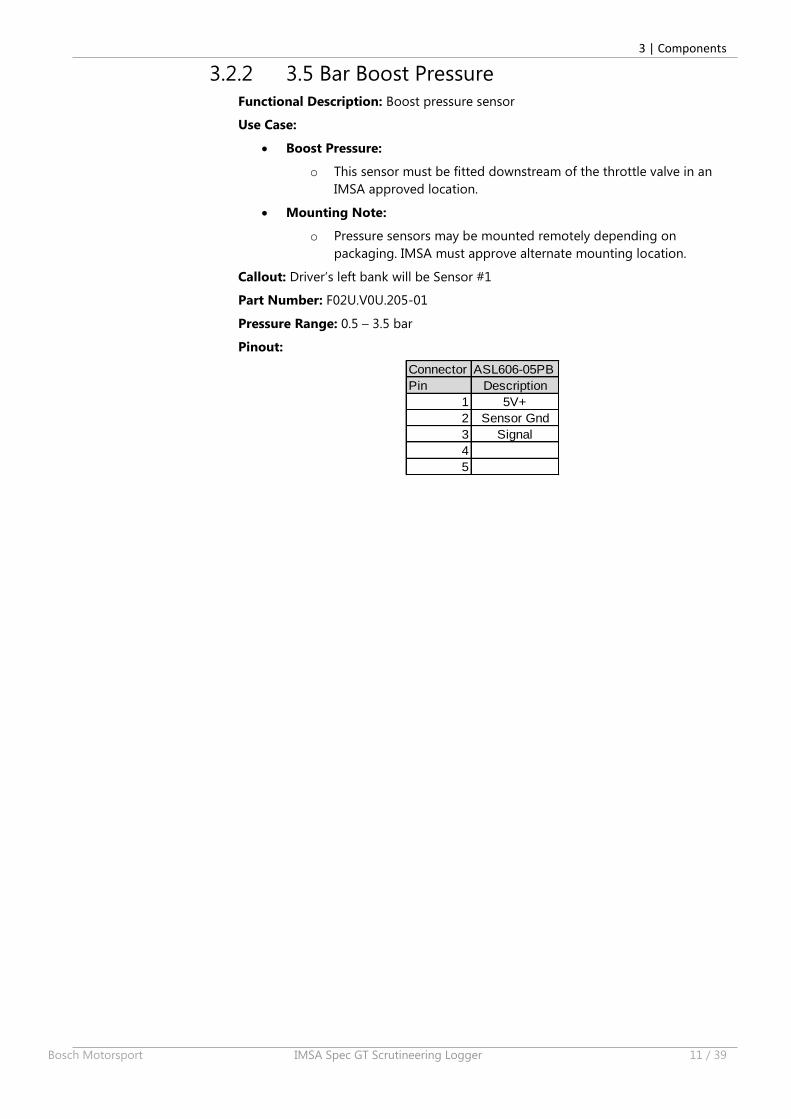
3.2.2 3.5 Bar Boost Pressure
Functional Description: Boost pressure sensor
Use Case:
Boost Pressure:
o This sensor must be fitted downstream of the throttle valve in an
IMSA approved location.
Mounting Note:
o Pressure sensors may be mounted remotely depending on
packaging. IMSA must approve alternate mounting location.
Callout: Driver’s left bank will be Sensor #1
Part Number: F02U.V0U.205-01
Pressure Range: 0.5 – 3.5 bar
Pinout:
Connector ASL606-05PB
Pin Description
1 5V+
2 Sensor Gnd
3 Signal
4
5
3 | Components
12 / 39 IMSA Spec GT Scrutineering Logger Bosch Motorsport
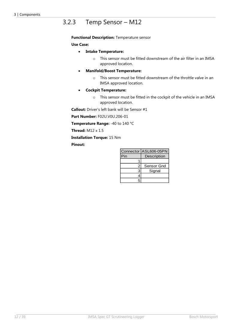
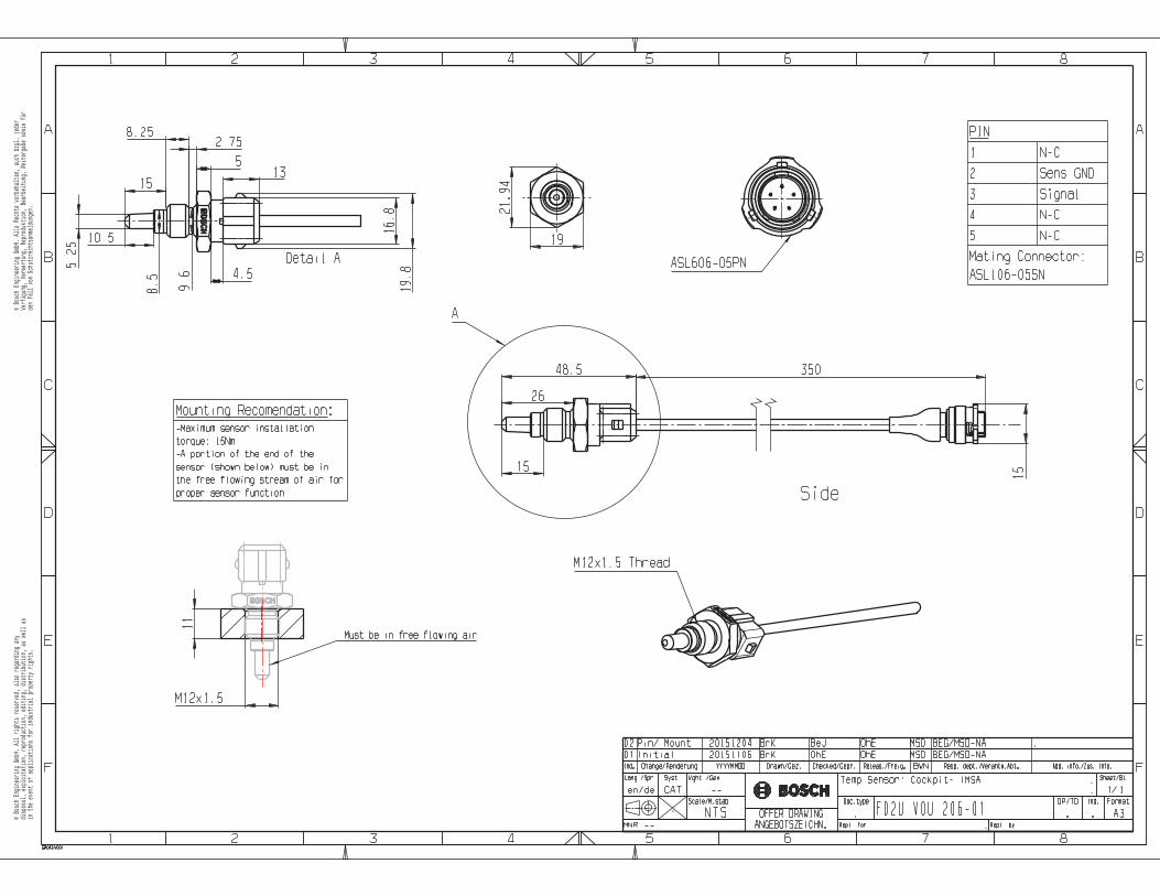
3.2.3 Temp Sensor – M12
Functional Description: Temperature sensor
Use Case:
Intake Temperature:
o This sensor must be fitted downstream of the air filter in an IMSA
approved location.
Manifold/Boost Temperature:
o This sensor must be fitted downstream of the throttle valve in an
IMSA approved location.
Cockpit Temperature:
o This sensor must be fitted in the cockpit of the vehicle in an IMSA
approved location.
Callout: Driver’s left bank will be Sensor #1
Part Number: F02U.V0U.206-01
Temperature Range: -40 to 140 °C
Thread: M12 x 1.5
Installation Torque: 15 Nm
Pinout:
Connector ASL606-05PN
Pin Description
1
2 Sensor Gnd
3 Signal
4
5
3 | Components
Bosch Motorsport IMSA Spec GT Scrutineering Logger 13 / 39
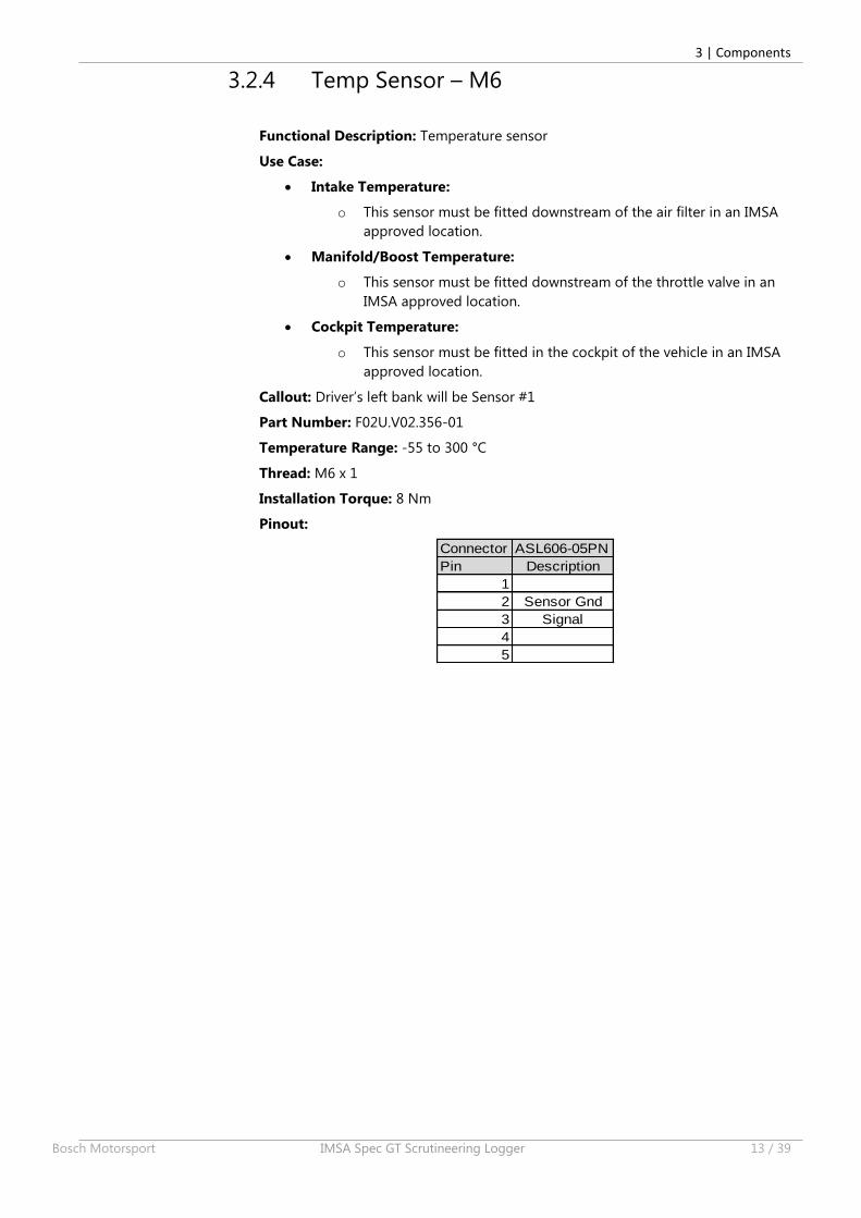
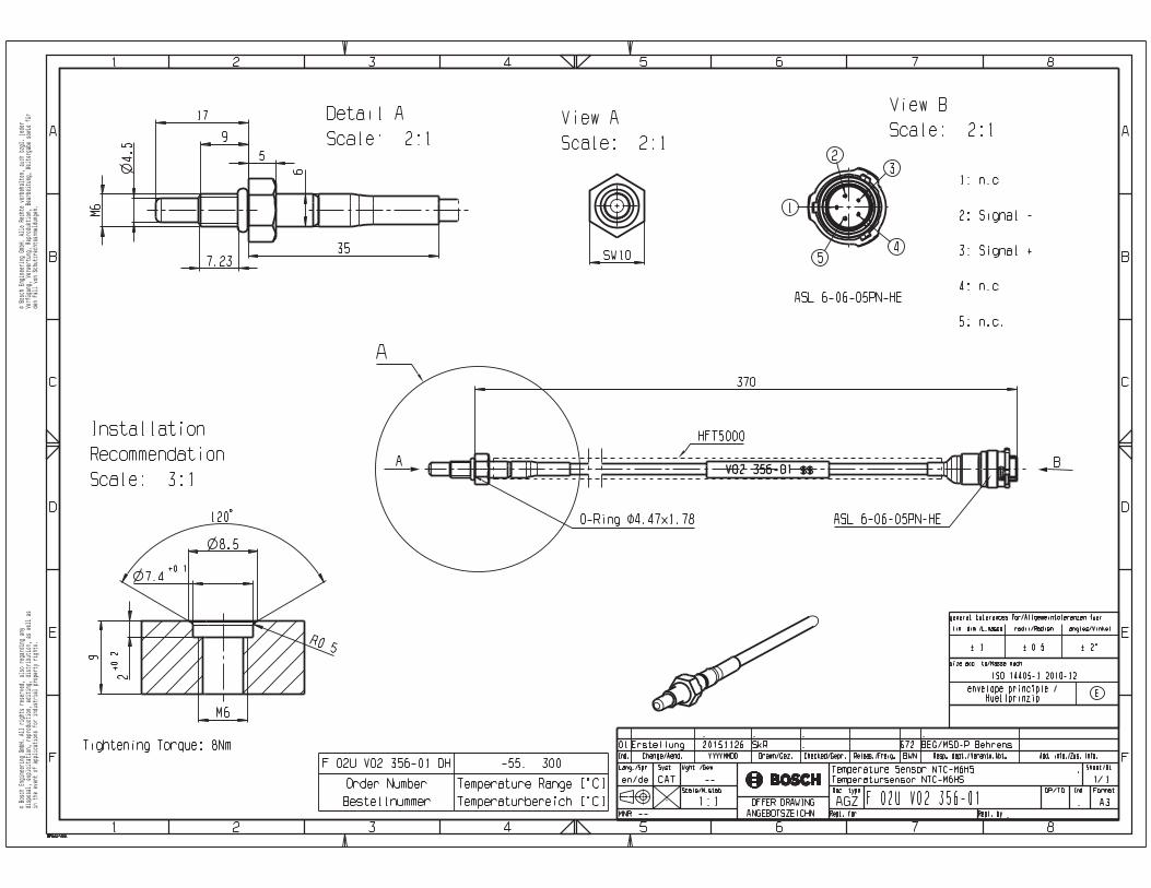
3.2.4 Temp Sensor – M6
Functional Description: Temperature sensor
Use Case:
Intake Temperature:
o This sensor must be fitted downstream of the air filter in an IMSA
approved location.
Manifold/Boost Temperature:
o This sensor must be fitted downstream of the throttle valve in an
IMSA approved location.
Cockpit Temperature:
o This sensor must be fitted in the cockpit of the vehicle in an IMSA
approved location.
Callout: Driver’s left bank will be Sensor #1
Part Number: F02U.V02.356-01
Temperature Range: -55 to 300 °C
Thread: M6 x 1
Installation Torque: 8 Nm
Pinout:
Connector ASL606-05PN
Pin Description
1
2 Sensor Gnd
3 Signal
4
5
3 | Components
14 / 39 IMSA Spec GT Scrutineering Logger Bosch Motorsport
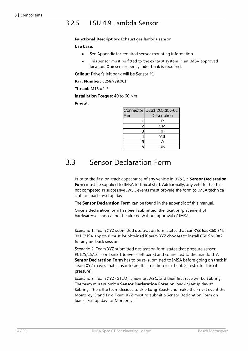
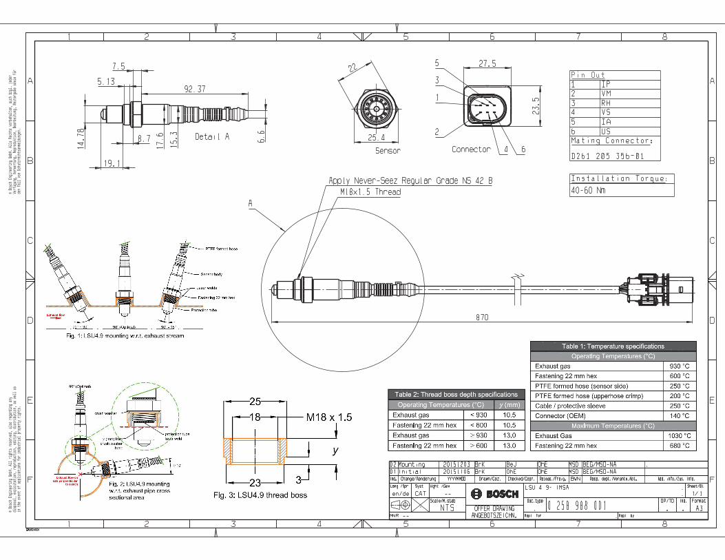
3.2.5 LSU 4.9 Lambda Sensor
Functional Description: Exhaust gas lambda sensor
Use Case:
See Appendix for required sensor mounting information.
This sensor must be fitted to the exhaust system in an IMSA approved
location. One sensor per cylinder bank is required.
Callout: Driver’s left bank will be Sensor #1
Part Number: 0258.988.001
Thread: M18 x 1.5
Installation Torque: 40 to 60 Nm
Pinout:
Connector D261.205.356-01
Pin Description
1 IP
2 VM
3 RH
4 VS
5 IA
6 UN
3.3 Sensor Declaration Form
Prior to the first on-track appearance of any vehicle in IWSC, a Sensor Declaration
Form must be supplied to IMSA technical staff. Additionally, any vehicle that has
not competed in successive IWSC events must provide the form to IMSA technical
staff on load-in/setup day.
The Sensor Declaration Form can be found in the appendix of this manual.
Once a declaration form has been submitted, the location/placement of
hardware/sensors cannot be altered without approval of IMSA.
Scenario 1: Team XYZ submitted declaration form states that car XYZ has C60 SN:
001, IMSA approval must be obtained if team XYZ chooses to install C60 SN: 002
for any on-track session.
Scenario 2: Team XYZ submitted declaration form states that pressure sensor
R0125/15/16 is on bank 1 (driver’s left bank) and connected to the manifold. A
Sensor Declaration Form has to be re-submitted to IMSA before going on track if
Team XYZ moves that sensor to another location (e.g. bank 2, restrictor throat
pressure).
Scenario 3: Team XYZ (GTLM) is new to IWSC, and their first race will be Sebring.
The team must submit a Sensor Declaration Form on load-in/setup day at
Sebring. Then, the team decides to skip Long Beach and make their next event the
Monterey Grand Prix. Team XYZ must re-submit a Sensor Declaration Form on
load-in/setup day for Monterey.
4 | System Architecture
Bosch Motorsport IMSA Spec GT Scrutineering Logger 15 / 39
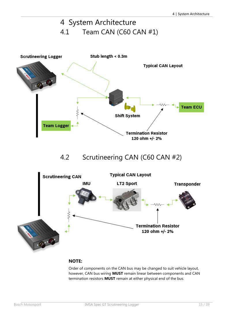
4 System Architecture
4.1 Team CAN (C60 CAN #1)
4.2 Scrutineering CAN (C60 CAN #2)
NOTE:
Order of components on the CAN bus may be changed to suit vehicle layout,
however, CAN bus wiring MUST remain linear between components and CAN
termination resistors MUST remain at either physical end of the bus.
4 | System Architecture
16 / 39 IMSA Spec GT Scrutineering Logger Bosch Motorsport
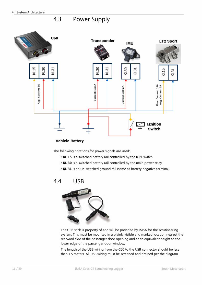
4.3 Power Supply
The following notations for power signals are used:
▪ KL 15 is a switched battery rail controlled by the IGN‐switch
▪ KL 30 is a switched battery rail controlled by the main power relay
▪ KL 31 is an un-switched ground rail (same as battery negative terminal)
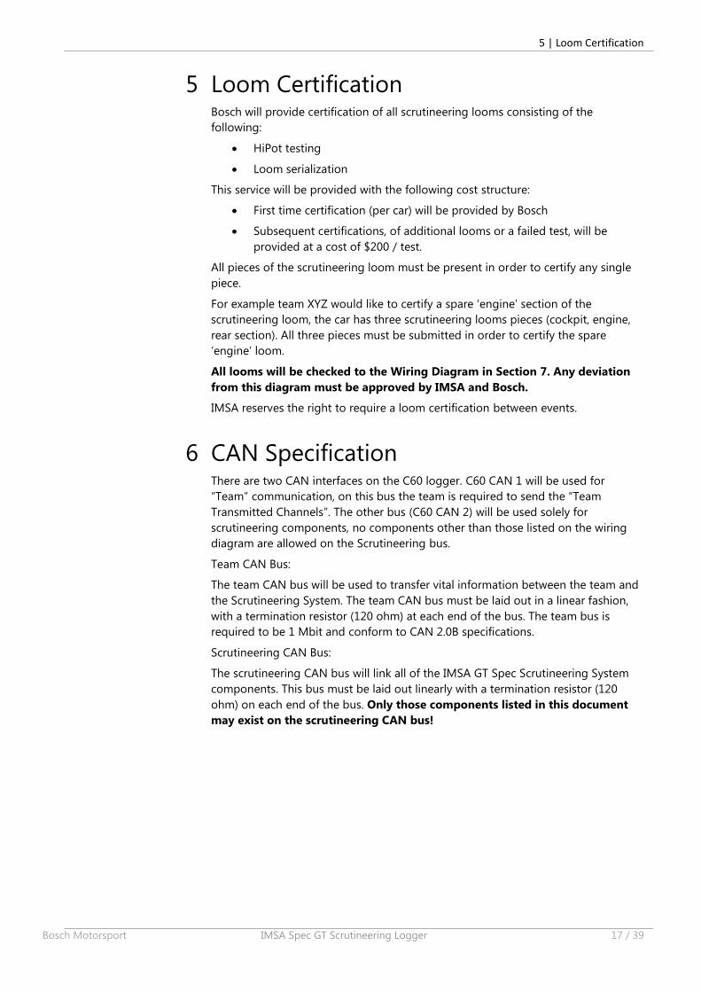
4.4 USB
The USB stick is property of and will be provided by IMSA for the scrutineering
system. This must be mounted in a plainly visible and marked location nearest the
rearward side of the passenger door opening and at an equivalent height to the
lower edge of the passenger door window.
The length of the USB wiring from the C60 to the USB connector should be less
than 1.5 meters. All USB wiring must be screened and drained per the diagram.
5 | Loom Certification
Bosch Motorsport IMSA Spec GT Scrutineering Logger 17 / 39
5 Loom Certification Bosch will provide certification of all scrutineering looms consisting of the
following:
HiPot testing
Loom serialization
This service will be provided with the following cost structure:
First time certification (per car) will be provided by Bosch
Subsequent certifications, of additional looms or a failed test, will be
provided at a cost of $200 / test.
All pieces of the scrutineering loom must be present in order to certify any single
piece.
For example team XYZ would like to certify a spare ‘engine’ section of the
scrutineering loom, the car has three scrutineering looms pieces (cockpit, engine,
rear section). All three pieces must be submitted in order to certify the spare
‘engine’ loom.
All looms will be checked to the Wiring Diagram in Section 7. Any deviation
from this diagram must be approved by IMSA and Bosch.
IMSA reserves the right to require a loom certification between events.
6 CAN Specification There are two CAN interfaces on the C60 logger. C60 CAN 1 will be used for
“Team” communication, on this bus the team is required to send the “Team
Transmitted Channels”. The other bus (C60 CAN 2) will be used solely for
scrutineering components, no components other than those listed on the wiring
diagram are allowed on the Scrutineering bus.
Team CAN Bus:
The team CAN bus will be used to transfer vital information between the team and
the Scrutineering System. The team CAN bus must be laid out in a linear fashion,
with a termination resistor (120 ohm) at each end of the bus. The team bus is
required to be 1 Mbit and conform to CAN 2.0B specifications.
Scrutineering CAN Bus:
The scrutineering CAN bus will link all of the IMSA GT Spec Scrutineering System
components. This bus must be laid out linearly with a termination resistor (120
ohm) on each end of the bus. Only those components listed in this document
may exist on the scrutineering CAN bus!
6 | CAN Specification
18 / 39 IMSA Spec GT Scrutineering Logger Bosch Motorsport
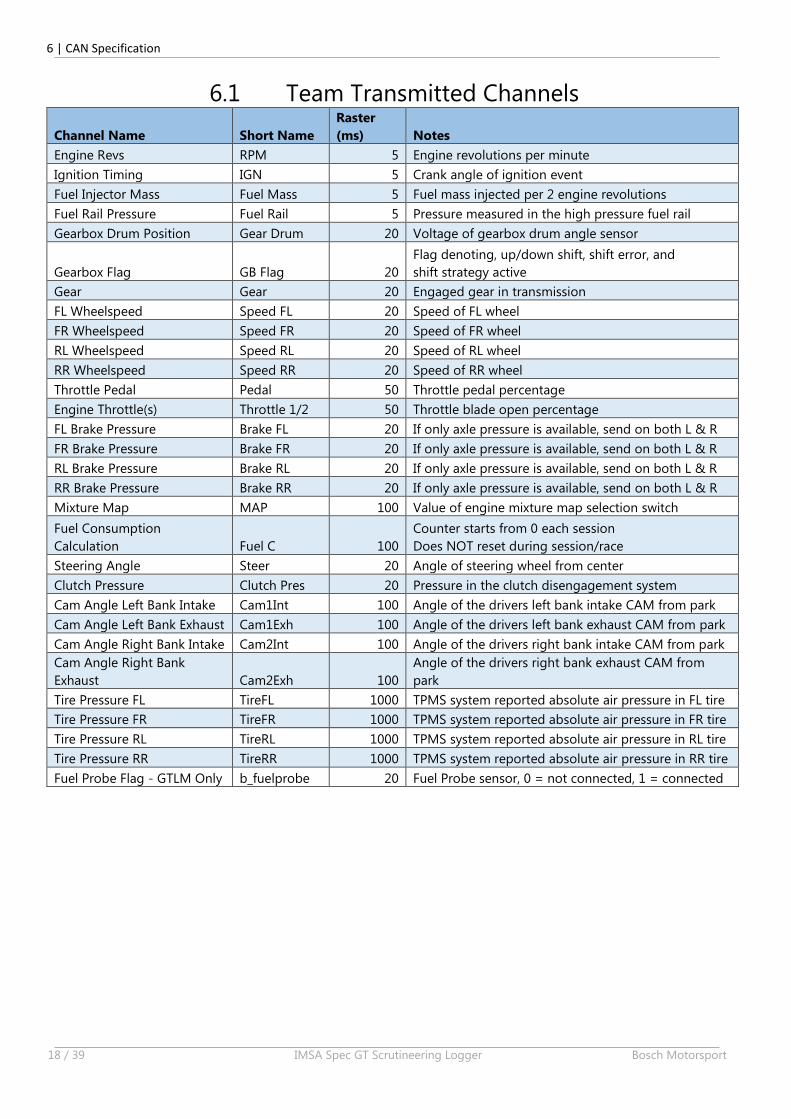
6.1 Team Transmitted Channels
Channel Name Short Name
Raster
(ms) Notes
Engine Revs RPM 5 Engine revolutions per minute
Ignition Timing IGN 5 Crank angle of ignition event
Fuel Injector Mass Fuel Mass 5 Fuel mass injected per 2 engine revolutions
Fuel Rail Pressure Fuel Rail 5 Pressure measured in the high pressure fuel rail
Gearbox Drum Position Gear Drum 20 Voltage of gearbox drum angle sensor
Gearbox Flag GB Flag 20
Flag denoting, up/down shift, shift error, and
shift strategy active
Gear Gear 20 Engaged gear in transmission
FL Wheelspeed Speed FL 20 Speed of FL wheel
FR Wheelspeed Speed FR 20 Speed of FR wheel
RL Wheelspeed Speed RL 20 Speed of RL wheel
RR Wheelspeed Speed RR 20 Speed of RR wheel
Throttle Pedal Pedal 50 Throttle pedal percentage
Engine Throttle(s) Throttle 1/2 50 Throttle blade open percentage
FL Brake Pressure Brake FL 20 If only axle pressure is available, send on both L & R
FR Brake Pressure Brake FR 20 If only axle pressure is available, send on both L & R
RL Brake Pressure Brake RL 20 If only axle pressure is available, send on both L & R
RR Brake Pressure Brake RR 20 If only axle pressure is available, send on both L & R
Mixture Map MAP 100 Value of engine mixture map selection switch
Fuel Consumption
Calculation Fuel C 100
Counter starts from 0 each session
Does NOT reset during session/race
Steering Angle Steer 20 Angle of steering wheel from center
Clutch Pressure Clutch Pres 20 Pressure in the clutch disengagement system
Cam Angle Left Bank Intake Cam1Int 100 Angle of the drivers left bank intake CAM from park
Cam Angle Left Bank Exhaust Cam1Exh 100 Angle of the drivers left bank exhaust CAM from park
Cam Angle Right Bank Intake Cam2Int 100 Angle of the drivers right bank intake CAM from park
Cam Angle Right Bank
Exhaust Cam2Exh 100
Angle of the drivers right bank exhaust CAM from
park
Tire Pressure FL TireFL 1000 TPMS system reported absolute air pressure in FL tire
Tire Pressure FR TireFR 1000 TPMS system reported absolute air pressure in FR tire
Tire Pressure RL TireRL 1000 TPMS system reported absolute air pressure in RL tire
Tire Pressure RR TireRR 1000 TPMS system reported absolute air pressure in RR tire
Fuel Probe Flag - GTLM Only b_fuelprobe 20 Fuel Probe sensor, 0 = not connected, 1 = connected

6 | CAN Specification
Bosch Motorsport IMSA Spec GT Scrutineering Logger 19 / 39
Byte 0 MSB
Byte 1 LSB
Byte 2 MSB
Byte 3 LSB
Byte 4 MSB
Byte 5 LSB
Byte 6 MSB
Byte 7 LSBIGN
S16 Angle : 1 bit / 0.1 deg
- after TDC : + before TDC
5ms Packet -RPM, Fuel, Ign - CAN id 0x240
Fuel Mass U16 Mass : 1 bit / 1 mg
Fuel Rail S16 Pressure : 1 bit/ 0.1 barA
RPM U16 RPM : 1 bit / 1 rpm
Byte 0 MSB
Byte 1 LSB
Byte 2 MSB
Byte 3 LSB
Byte 4 MSB
Byte 5 LSB
Byte 6 MSB
Byte 7 LSBSpeed RR U16 Speed : 1 bit / 0.1 km/h
Speed RL U16 Speed : 1 bit / 0.1 km/h
20ms Packet - Wheelspeeds - CAN id 0x241
Speed FL U16 Speed : 1 bit / 0.1 km/h
Speed FR U16 Speed : 1 bit / 0.1 km/h
Byte 0 MSB
Byte 1 LSB
Byte 2 MSB
Byte 3 LSB
Byte 4 MSB
Byte 5 LSB
Byte 6 MSB
Byte 7 LSB
50ms Packet - Throttles - CAN id 0x242
Pedal S16 Percent : 1 bit / 0.1 %
Throttle 1 S16 Percent : 1 bit / 0.1 %
Throttle 2 S16 Percent : 1 bit / 0.1 %
Byte 0 MSB
Byte 1 LSB
Byte 2 MSB
Byte 3 LSB
Byte 4 MSB
Byte 5 LSB
Byte 6 MSB
Byte 7 LSB
Brake FL S16 Pressure : 1 bit/ 0.1 barR
20ms Packet - Brakes - CAN id 0x243
Brake FR S16 Pressure : 1 bit/ 0.1 barR
Brake RL S16 Pressure : 1 bit/ 0.1 barR
Brake RR S16 Pressure : 1 bit/ 0.1 barR
Byte 0 MSB
Byte 1 LSB
Byte 2 MSB
Byte 3 MAP MSB U8 : 1 bit / 1 position
Byte 4 MSB
Byte 5
Byte 6
Byte 7 LSB
Fuel C U32 Volume : 1 bit/ 0.01 liter
100ms Packet - MAP & Fuel - CAN id 0x244
6 | CAN Specification
20 / 39 IMSA Spec GT Scrutineering Logger Bosch Motorsport
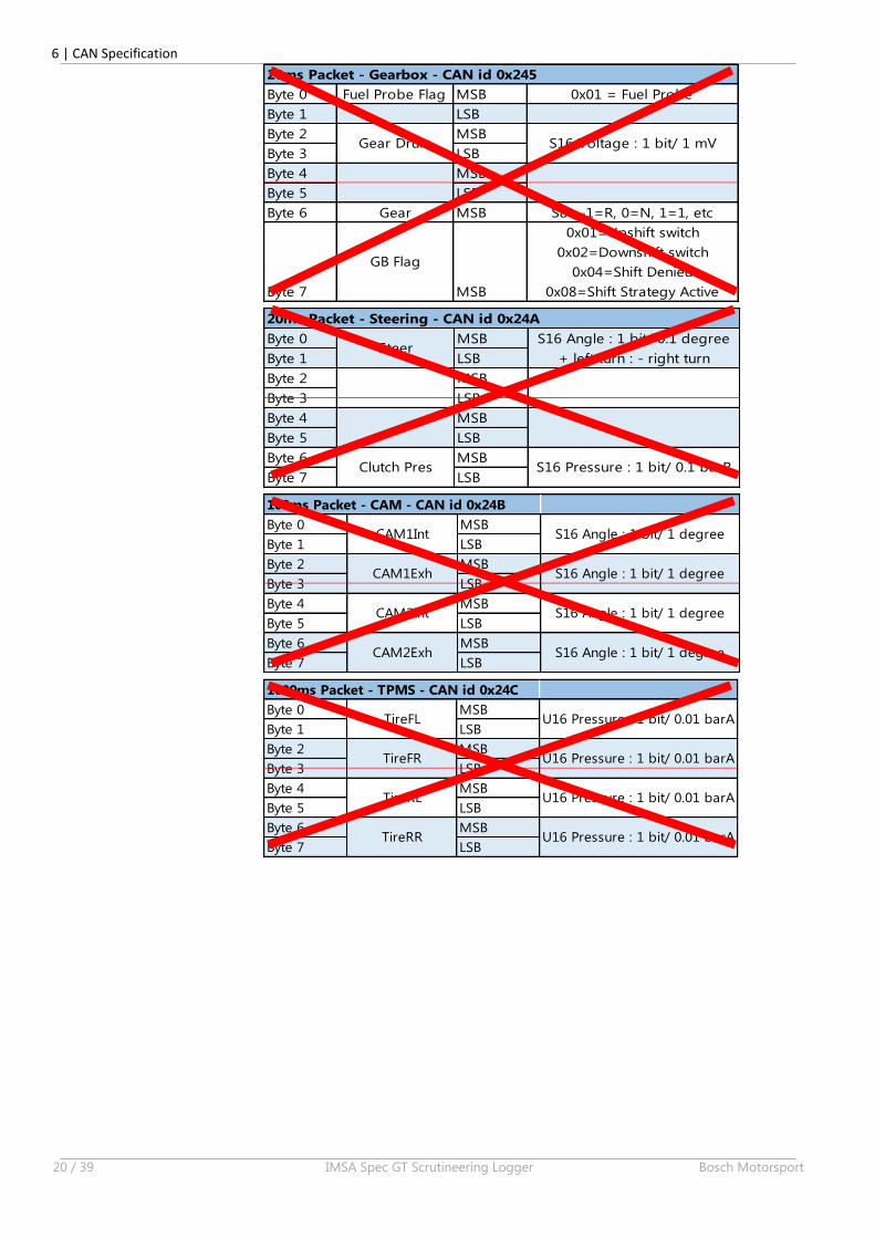
Byte 0 Fuel Probe Flag MSB 0x01 = Fuel Probe
Byte 1 LSB
Byte 2 MSB
Byte 3 LSB
Byte 4 MSB
Byte 5 LSB
Byte 6 Gear MSB S8 : -1=R, 0=N, 1=1, etc
Byte 7
GB Flag
MSB
0x01=Upshift switch
0x02=Downshift switch
0x04=Shift Denied
0x08=Shift Strategy Active
Gear Drum S16 Voltage : 1 bit/ 1 mV
20ms Packet - Gearbox - CAN id 0x245
Byte 0 MSB
Byte 1 LSB
Byte 2 MSB
Byte 3 LSB
Byte 4 MSB
Byte 5 LSB
Byte 6 MSB
Byte 7 LSB
20ms Packet - Steering - CAN id 0x24A
SteerS16 Angle : 1 bit/ 0.1 degree
+ left turn : - right turn
Clutch Pres S16 Pressure : 1 bit/ 0.1 barR
100ms Packet - CAM - CAN id 0x24B
Byte 0 MSB
Byte 1 LSB
Byte 2 MSB
Byte 3 LSB
Byte 4 MSB
Byte 5 LSB
Byte 6 MSB
Byte 7 LSB
CAM1Int S16 Angle : 1 bit/ 1 degree
S16 Angle : 1 bit/ 1 degree
S16 Angle : 1 bit/ 1 degree
S16 Angle : 1 bit/ 1 degree
CAM1Exh
CAM2Int
CAM2Exh
1000ms Packet - TPMS - CAN id 0x24C
Byte 0 MSB
Byte 1 LSB
Byte 2 MSB
Byte 3 LSB
Byte 4 MSB
Byte 5 LSB
Byte 6 MSB
Byte 7 LSB
TireFL
TireFR
TireRL
TireRR U16 Pressure : 1 bit/ 0.01 barA
U16 Pressure : 1 bit/ 0.01 barA
U16 Pressure : 1 bit/ 0.01 barA
U16 Pressure : 1 bit/ 0.01 barA
6 | CAN Specification
Bosch Motorsport IMSA Spec GT Scrutineering Logger 21 / 39
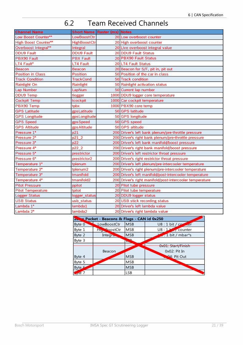
6.2 Team Received Channels
20ms Packet - Beacons & Flags - CAN id 0x250
Byte 0 LowBoostCtr MSB U8 : 1 bit / counter
Byte 1 HighBoostCtr MSB U8 : 1 bit / counter
Byte 2 Integral MSB U8 : 1 bit / mbar*s
Byte 3 LSB
Byte 4
Beacon
MSB
0x01: Start/Finish
0x02: Pit In
0x04: Pit Out
Byte 5 MSB
Byte 6 MSB
Byte 7 LSB
Channel Name Short Name Raster (ms) Notes
Low Boost Counter** LowBoostCtr 20 Low overboost counter
High Boost Counter** HighBoostCtr 20 High overboost counter
Overboost Integral** Integral 20 Live overboost integral value
DDU9 Fault DDU9 Fault 20 DDU9 Fault Status
PBX90 Fault PBX Fault 20 PBX90 Fault Status
LT4 Fault* LT4 Fault 20 LT4 Fault Status
Beacon Beacon 20 Beacon for S/F, pit in, pit out
Position in Class Position 50 Position of the car in class
Track Condition TrackCond 50 Track condition
Rainlight On Rainlight 50 Rainlight activation status
Lap Number LapNum 50 Current lap number
DDU9 Temp tlogger 1000 DDU9 logger core temperature
Cockpit Temp tcockpit 1000 Car cockpit temperature
PBX90 Temp tpbx 1000 PBX90 core temp
GPS Latitude gpsLatitude 50 GPS latitude
GPS Longitude gpsLongitude 50 GPS longitude
GPS Speed gpsSpeed 50 GPS speed
GPS Altitude gpsAltitude 50 GPS altitude
Pressure 1* p21 200 Driver's left bank plenum/pre-throttle pressure
Pressure 2* p21_2 200 Driver's right bank plenum/pre-throttle pressure
Pressure 3* p22 200 Driver's left bank manifold/boost pressure
Pressure 4* p22_2 200 Driver's right bank manifold/boost pressure
Pressure 5* prestrictor 200 Driver's left restrictor throat pressure
Pressure 6* prestrictor2 200 Driver's right restrictor throat pressure
Temperature 1* tplenum 200 Driver's left plenum/pre-intercooler temperature
Temperature 2* tplenum2 200 Driver's right plenum/pre-intercooler temperature
Temperature 3* tmanifold 200 Driver's left manifold/post-intercooler temperature
Temperature 4* tmanifold2 200 Driver's right manifold/post-intercooler temperature
Pitot Pressure ppitot 20 Pitot tube pressure
Pitot Temperature tpitot 20 Pitot tube temperature
Logger Status logger_status 20 DDU9 logger status
USB Status usb_status 20 USB stick recording status
Lambda 1* lambda1 20 Driver's left lambda value
Lambda 2* lambda2 20 Driver's right lambda value
6 | CAN Specification
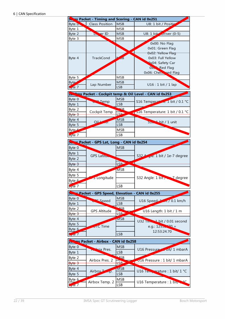
22 / 39 IMSA Spec GT Scrutineering Logger Bosch Motorsport
Byte 0 Class Position MSB U8: 1 bit / Position
Byte 1 MSB
Byte 2 Driver ID MSB U8: 1 bit / Driver (0-5)
Byte 3 MSB
Byte 4 TrackCond MSB
0x00: No Flag
0x01: Green Flag
0x02: Yellow Flag
0x03: Full Yellow
0x04: Safety Car
0x05: Red Flag
0x06: Checkered Flag
Byte 5 MSB
Byte 6 MSB
Byte 7 LSB
50ms Packet - Timing and Scoring - CAN id 0x251
Lap Number U16 : 1 bit / 1 lap
Byte 0 MSB
Byte 1 LSB
Byte 2 MSB
Byte 3 LSB
Byte 4 MSB
Byte 5 LSB
Byte 6 MSB
Byte 7 LSB
Oil Level S16: 1 bit / 1 unit
1000ms Packet - Cockpit temp & Oil Level - CAN id 0x253
C60 Temp S16 Temperature: 1 bit / 0.1 °C
Cockpit Temp S16 Temperature: 1 bit / 0.1 °C
Byte 0 MSB
Byte 1
Byte 2
Byte 3 LSB
Byte 4 MSB
Byte 5
Byte 6
Byte 7 LSB
GPS Latitude
GPS Longitude
S32 Angle: 1 bit / 1e-7 degree
S32 Angle: 1 bit / 1e-7 degree
50ms Packet - GPS Lat, Long - CAN id 0x254
Byte 0 MSB
Byte 1 LSB
Byte 2 MSB
Byte 3 LSB
Byte 4 MSB
Byte 5
Byte 6
Byte 7 LSB
50ms Packet - GPS Speed, Elevation - CAN id 0x255
GPS Speed U16 Speed: 1 bit / 0.1 km/h
GPS Altitude U16 Length: 1 bit / 1 m
UTC Time
U32 Time: 1 bit / 0.01 second
e.g.: 12532470 =
12:53:24.70
Byte 0 MSB
Byte 1 LSB
Byte 2 MSB
Byte 3 LSB
Byte 4 MSB
Byte 5 LSB
Byte 6 MSB
Byte 7 LSB
U16 Pressure : 1 bit/ 1 mbarAAirbox Pres.
Airbox Pres. 2 U16 Pressure : 1 bit/ 1 mbarA
200ms Packet - Airbox - CAN id 0x258
U16 Temperature : 1 bit/ 1 °C
U16 Temperature : 1 bit/ 1 °C
Airbox Temp.
Airbox Temp. 2
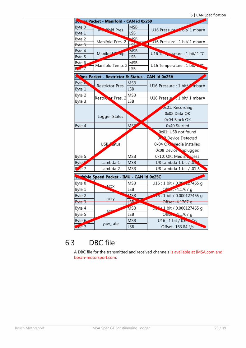
6 | CAN Specification
Bosch Motorsport IMSA Spec GT Scrutineering Logger 23 / 39
Byte 0 MSB
Byte 1 LSB
Byte 2 MSB
Byte 3 LSB
Byte 4 MSB
Byte 5 LSB
Byte 6 MSB
Byte 7 LSB
U16 Pressure : 1 bit/ 1 mbarA
U16 Pressure : 1 bit/ 1 mbarA
U16 Temperature : 1 bit/ 1 °C
U16 Temperature : 1 bit/ 1 °C
Manifold Pres.
Manifold Pres. 2
Manifold Temp.
Manifold Temp. 2
200ms Packet - Manifold - CAN id 0x259
Byte 0 MSB
Byte 1 LSB
Byte 2 MSB
Byte 3 LSB
Byte 4
Logger Status
MSB
0x01: Recording
0x02 Data OK
0x04 Block OK
0x40 Started
Byte 5
USB Status
MSB
0x01: USB not found
0x02 Device Detected
0x04 OK: Media Installed
0x08 Device Unplugged
0x10: OK: Media Access
Byte 6 Lambda 1 MSB U8 Lambda 1 bit / .01 λ
Byte 7 Lambda 2 MSB U8 Lambda 1 bit / .01 λ
200ms Packet - Restrictor & Status - CAN id 0x25A
Restrictor Pres. U16 Pressure : 1 bit/ 1 mbarA
Restrictor Pres. 2 U16 Pressure : 1 bit/ 1 mbarA
Byte 0 MSB
Byte 1 LSB
Byte 2 MSB
Byte 3 LSB
Byte 4 MSB
Byte 5 LSB
Byte 6 MSB
Byte 7 LSB
Variable Speed Packet - IMU - CAN id 0x25C
accx
acczU16 : 1 bit / 0.000127465 g
Offset -4.1767 g
U16 : 1 bit / 0.000127465 g
Offset -4.1767 g
accyU16 : 1 bit / 0.000127465 g
Offset -4.1767 g
U16 : 1 bit / 0.005 °/s
Offset -163.84 °/syaw_rate
6.3 DBC file A DBC file for the transmitted and received channels is available at IMSA.com and
bosch-motorsport.com.

Customer Information Dealer Contact Information CMS Email [email protected] Phone +1 (813) 482-2178
Email [email protected] / Fax +1 (714) 446-9473 / +1 (714) 446-9247Email [email protected]
New York Phone / Fax +1 (631) 423-0523 / +1 (631) 423-7769
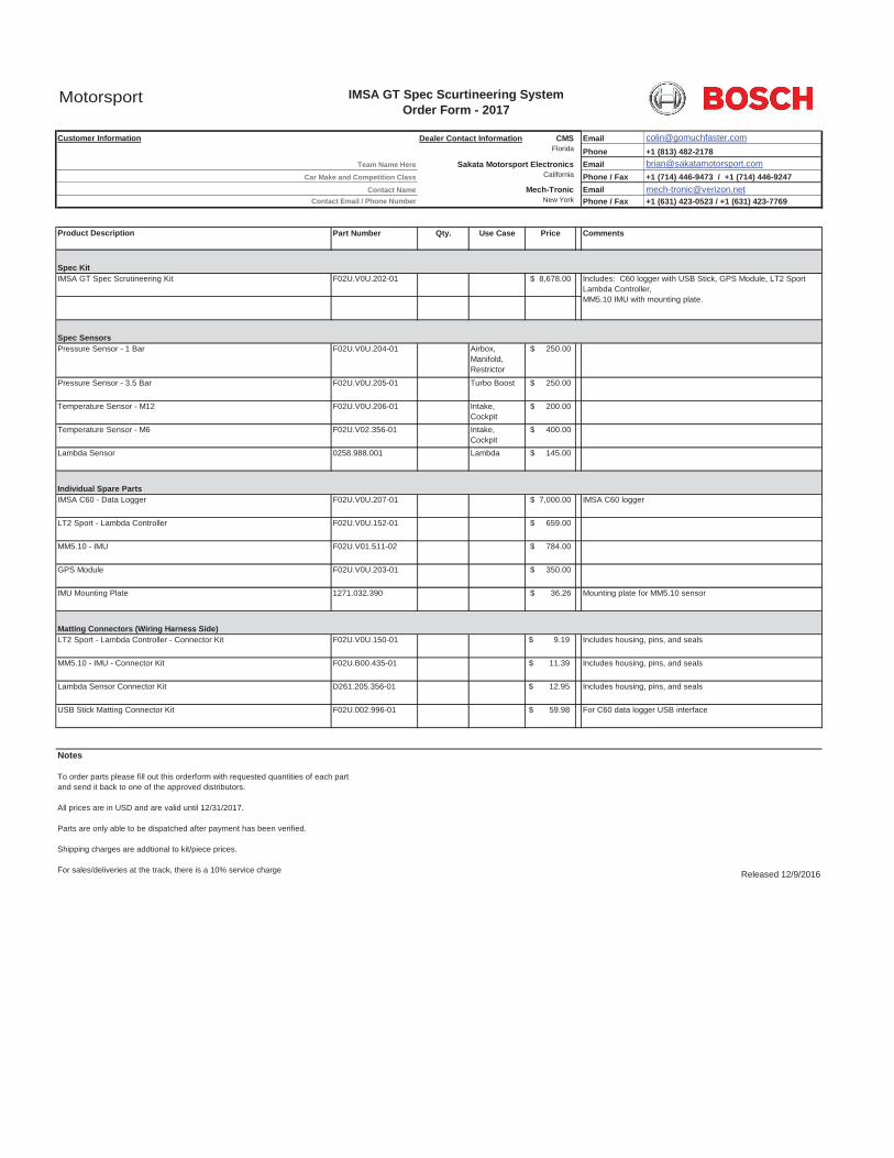
Product Description Part Number Qty. Use Case Price
Spec KitIMSA GT Spec Scrutineering Kit F02U.V0U.202-01 8,678.00$
Spec SensorsPressure Sensor - 1 Bar F02U.V0U.204-01 Airbox,
Manifold, Restrictor
250.00$
Pressure Sensor - 3.5 Bar F02U.V0U.205-01 Turbo Boost 250.00$
Temperature Sensor - M12 F02U.V0U.206-01 Intake, Cockpit
200.00$
Temperature Sensor - M6 F02U.V02.356-01 Intake, Cockpit
400.00$
Lambda Sensor 0258.988.001 Lambda 145.00$
Individual Spare PartsIMSA C60 - Data Logger F02U.V0U.207-01 7,000.00$
LT2 Sport - Lambda Controller F02U.V0U.152-01 659.00$
MM5.10 - IMU F02U.V01.511-02 784.00$
GPS Module F02U.V0U.203-01 350.00$
IMU Mounting Plate 1271.032.390 36.26$
Matting Connectors (Wiring Harness Side)LT2 Sport - Lambda Controller - Connector Kit F02U.V0U.150-01 $ 9.19
MM5.10 - IMU - Connector Kit F02U.B00.435-01 $ 11.39
Lambda Sensor Connector Kit D261.205.356-01 $ 12.95
USB Stick Matting Connector Kit F02U.002.996-01 $ 59.98
Notes
To order parts please fill out this orderform with requested quantities of each part and send it back to one of the approved distributors.
All prices are in USD and are valid until 12/31/2017.
Parts are only able to be dispatched after payment has been verified.
Shipping charges are addtional to kit/piece prices.
For sales/deliveries at the track, there is a 10% service charge Released 12/9/2016
IMSA GT Spec Scurtineering System Order Form - 2017
Sakata Motorsport Electronics
Comments
Includes: C60 logger with USB Stick, GPS Module, LT2 Sport Lambda Controller,MM5.10 IMU with mounting plate.
Mech-Tronic
California
IMSA C60 logger
Includes housing, pins, and seals
Includes housing, pins, and seals
Includes housing, pins, and seals
For C60 data logger USB interface
Team Name Here
Car Make and Competition Class
Contact NameContact Email / Phone Number
Mounting plate for MM5.10 sensor
Motorsport
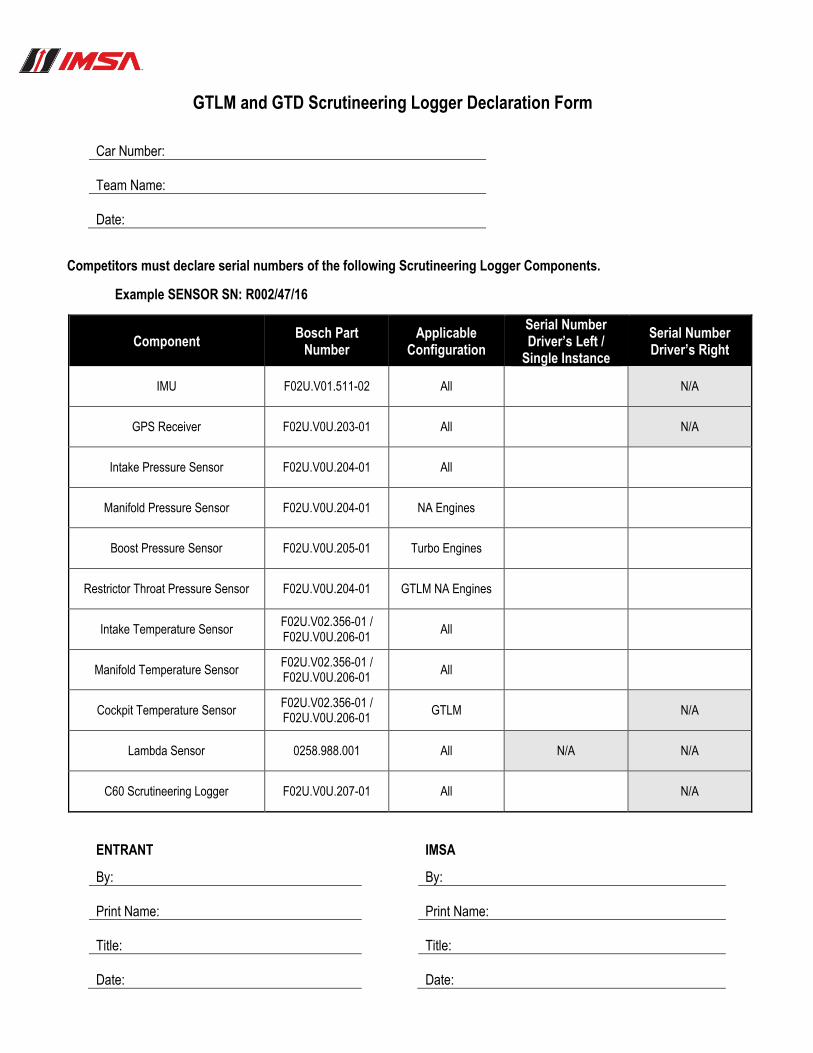
GTLM and GTD Scrutineering Logger Declaration Form
Car Number: 1. Team Name: 2. Date: 3.
Competitors must declare serial numbers of the following Scrutineering Logger Components.
Example SENSOR SN: R002/47/16
Component Bosch Part
Number Applicable
Configuration
Serial Number Driver’s Left /
Single Instance
Serial Number Driver’s Right
IMU F02U.V01.511-02 All N/A
GPS Receiver F02U.V0U.203-01 All N/A
Intake Pressure Sensor F02U.V0U.204-01 All
Manifold Pressure Sensor F02U.V0U.204-01 NA Engines
Boost Pressure Sensor F02U.V0U.205-01 Turbo Engines
Restrictor Throat Pressure Sensor F02U.V0U.204-01 GTLM NA Engines
Intake Temperature Sensor F02U.V02.356-01 / F02U.V0U.206-01
All
Manifold Temperature Sensor F02U.V02.356-01 / F02U.V0U.206-01
All
Cockpit Temperature Sensor F02U.V02.356-01 / F02U.V0U.206-01
GTLM N/A
Lambda Sensor 0258.988.001 All N/A N/A
C60 Scrutineering Logger F02U.V0U.207-01 All N/A
ENTRANT 4. IMSA
By: 5. By:
Print Name: 6. Print Name:
Title: 7. Title:
Date: 8. Date:
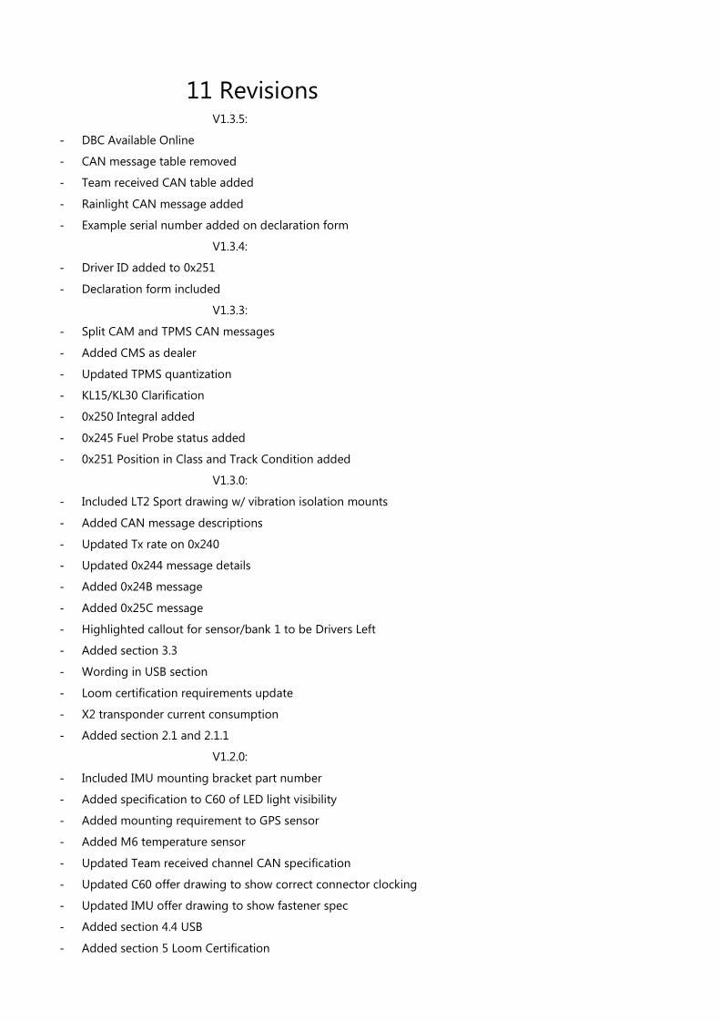
11 Revisions
V1.3.5:
- DBC Available Online
- CAN message table removed
- Team received CAN table added
- Rainlight CAN message added
- Example serial number added on declaration form
V1.3.4:
- Driver ID added to 0x251
- Declaration form included
V1.3.3:
- Split CAM and TPMS CAN messages
- Added CMS as dealer
- Updated TPMS quantization
- KL15/KL30 Clarification
- 0x250 Integral added
- 0x245 Fuel Probe status added
- 0x251 Position in Class and Track Condition added
V1.3.0:
- Included LT2 Sport drawing w/ vibration isolation mounts
- Added CAN message descriptions
- Updated Tx rate on 0x240
- Updated 0x244 message details
- Added 0x24B message
- Added 0x25C message
- Highlighted callout for sensor/bank 1 to be Drivers Left
- Added section 3.3
- Wording in USB section
- Loom certification requirements update
- X2 transponder current consumption
- Added section 2.1 and 2.1.1
V1.2.0:
- Included IMU mounting bracket part number
- Added specification to C60 of LED light visibility
- Added mounting requirement to GPS sensor
- Added M6 temperature sensor
- Updated Team received channel CAN specification
- Updated C60 offer drawing to show correct connector clocking
- Updated IMU offer drawing to show fastener spec
- Added section 4.4 USB
- Added section 5 Loom Certification

34 / 35 IMSA Spec GT Scrutineering Logger Bosch Motorsport
V1.1.0:
- Clarification on sensor numbering vs. left bank/right bank
- Added restrictor pressure sensor wiring to schematic
- Added notation on USB wiring length to schematic
- Updated section 3.1, mating connectors
- Updated LSU4.9 offer drawing
- Added mounting information on IMU to section 3.1.2
- Added Throttle 2 to TEAM CAN Spec
- Added order form to Appendix
V1.0.0 – Initial Release

© All rights reserved by Bosch Engineering GmbH,
also for the case of patent reports. All rights such
as copying and forwarding through us.
Modifications reserved.

11 Revisions
V1.3.5:
- DBC Available Online
- CAN message table removed
- Team received CAN table added
- Rainlight CAN message added
- Example serial number added on declaration form
V1.3.4:
- Driver ID added to 0x251
- Declaration form included
V1.3.3:
- Split CAM and TPMS CAN messages
- Added CMS as dealer
- Updated TPMS quantization
- KL15/KL30 Clarification
- 0x250 Integral added
- 0x245 Fuel Probe status added
- 0x251 Position in Class and Track Condition added
V1.3.0:
- Included LT2 Sport drawing w/ vibration isolation mounts
- Added CAN message descriptions
- Updated Tx rate on 0x240
- Updated 0x244 message details
- Added 0x24B message
- Added 0x25C message
- Highlighted callout for sensor/bank 1 to be Drivers Left
- Added section 3.3
- Wording in USB section
- Loom certification requirements update
- X2 transponder current consumption
- Added section 2.1 and 2.1.1
V1.2.0:
- Included IMU mounting bracket part number
- Added specification to C60 of LED light visibility
- Added mounting requirement to GPS sensor
- Added M6 temperature sensor
- Updated Team received channel CAN specification
- Updated C60 offer drawing to show correct connector clocking
- Updated IMU offer drawing to show fastener spec
- Added section 4.4 USB
- Added section 5 Loom Certification
38 / 39 IMSA Spec GT Scrutineering Logger Bosch Motorsport
V1.1.0:
- Clarification on sensor numbering vs. left bank/right bank
- Added restrictor pressure sensor wiring to schematic
- Added notation on USB wiring length to schematic
- Updated section 3.1, mating connectors
- Updated LSU4.9 offer drawing
- Added mounting information on IMU to section 3.1.2
- Added Throttle 2 to TEAM CAN Spec
- Added order form to Appendix
V1.0.0 – Initial Release

© All rights reserved by Bosch Engineering GmbH,
also for the case of patent reports. All rights such
as copying and forwarding through us.
Modifications reserved.