Embed Size (px)
Citation preview
IMS - Mobile Server PlatformThe foundation of
Mobile-to-Mobile service networksfor future cellular Systems
Von der Fakultat fur Mathematik, Informatik undNaturwissenschaften der RWTH Aachen University zur Erlangung des
akademischen Grades eines Doktors der Naturwissenschaftengenehmigte Dissertation
vorgelegt von
M.Sc.Muzzamil Aziz
aus Kuwait City, Kuwait
Berichter: Universitatsprofessor Dr. rer. pol. Matthias Jarke
Universitatsprofessor Dr.-Ing. Bernhard Walke
Tag der mundlichen Prufung: 9. Feb 2017
Diese Dissertation ist auf den Internetseiten der Universitatsbibliothek onlineverfugbar


“He grants wisdom to whom He pleases, and whoever is granted wisdom, he indeedis given a great good and none but men of understanding mind.”
Quran: Chapter 2, Verse 269

Abstract
The unprecedented growth of mobile application market is the evidence of twofoldtechnological advancement in the wireless world: first, the enormous increase inthe capacity of mobile networks and second, the rapid increase in the computingpowers of mobile devices. The former has enabled the network operators to ensurequality of service on their network by inducing more capacity for seamless datatransmissions. Whereas, the latter has contributed in the novel space of mobileserver paradigm, where the mobile devices are assumed to have sufficient computingpower of hosting and distributing small and medium-sized data services amongthe peers on the network. Nevertheless, considering the mobile server paradigm orpeer-to-peer mobile applications, the availability of such applications are mostlylimited to WiFi and Wireless Local Area Networks (WLAN) only and, hence, notavailable for cellular data networks. There are various technical and political reasonsbehind this phenomena.
The dissertation deals with the standardized provisioning of mobile applications oncellular data networks and addresses the issues related to it. A novel concept ofMobile-to-Mobile service networks is presented in this regard and a prototypicalimplementation of an IMS (IP Multimedia Subsystem) interfaced Mobile ServerPlatform (MSP) is provided to enable multimedia communication among the peers.The IMS was originally introduced by 3GPP to support heavy multimedia com-munication over 3G cellular network, which has now become an application layerstandard for 4G / LTE-Evolved Packet Core network.
From the architectural point of view, the MSP is mainly categorized into three dif-ferent logical frameworks. First, the Multimedia Messaging Framework is introducedin order to realize the mobile-to-mobile text messaging and multimedia file sharingfeatures in a service oriented fashion over the operator IMS network. The proposedframework conforms to the functional and non-functional requirements of the InstantMessaging (IM) service addressed by 3GPP.
Second, the Multimedia Streaming Framework is introduced in order to supportthe mobile-to-mobile multimedia sessions in a service oriented fashion over theoperator IMS network. The SIP and SDP are the main protocols used for thesession establishment process of the streaming applications, whereas, the RTP andRTSP protocols are proposed to provision standardized multimedia transmissionsand achieve remote control streaming features on top.
Third, a comprehensive QoS Framework is introduced to provide an efficient controlof ongoing multimedia sessions according to the Policy and Charging Control (PCC)mechanism devised by the 3GPP. The performance evaluation and mathematicalmodels of File Transfer Time (FTT) and Video Streaming Time (VST) are presentedfor different network conditions and for various types of user profiles.

Zusammenfassung
Das beispiellose Wachstum mobiler Anwendungen ist Ausdruck zweier zentralerFortschritte in der drahtlosen Mobilkommunikation: des enormen Zuwachses inder Kapazitat mobiler Netze der dritten und vierten Generation, und dem raschenZuwachs an Rechnerkapazitat und Energieeffizienz mobiler Endgerate. Die erstge-nannte Entwicklung erlaubt Netzbetreibern bruchlose Datendienste hoher Qualitatanzubieten, letztere Entwicklung gestattet sogar die Nutzung mobiler Endgerate alsMobile Service Provider in Peer-to-Peer-Netzen. Allerdings stellt die Kombinationbeider Effekte die Netzbetreiber heute noch vor erhebliche Probleme, so dass mobileServiceprovider derzeit schwerpunktmaßig noch auf WiFi und WLAN beschranktsind. Um dies zu andern, mussen sowohl technische als auch politische Hurden z.B.im Bereich der Standardeinhaltung uberwunden werden.
Die vorliegende Arbeit befasst sich mit der standardkonformen Bereitstellung mobilerAnwendungen in zellularen Netzen, wie sie von den Netzbetreibern heute undin Zukunft angeboten werden. Sie entwickelt ein neuartiges Mobile-zu-Mobile-Servicenetz und fokussiert dabei insbesondere auf die Implementierung von IPMultimedia-Subsystemen (IMS-Standard der 3GPP) fur Mobile Serviceprovider, umMultimedia-Kommunikation zwischen Peers zu unterstutzen, das nun eine Standard-Anwendungsschicht fur das Netz 4G/LTE-Evolved Paket Core geworden ist.
Konkret werden drei logische Rahmenwerke vorgestellt, prototypisch umgesetzt undempirisch evaluiert. Das Multimedia Messaging Framework realisiert mobil-zu-mobilTextnachrichten und Multimedia-Dateifreigabefunktionen in einer serviceorientiertenArt und Weise uber den IMS-Netzwerkbetreiber. Das Framework und seine Umset-zung entsprechen voll den funktionalen und nicht-funktionalen Anforderungen des3GPP Instant Messaging (IM) -Dienstes.
Das Multimedia Streaming Framework unterstutzt mobil-zu-mobil Multimedia-Sitzungen in einer serviceorientierten Art und Weise ebenfalls uber den IMS-Netzwerkbetreiber. SIP und SDP sind die wichtigsten verwendeten Protokolle fur denSitzungsaufbau der Streaminganwendungen, wahrend die RTP und RTSP-Protokollestandardisierte Multimediaubertragungen und ferngesteuerte Streamingfunktionenin den Griff bekommen.
Drittens wird ein umfassender QoS Rahmen eingefuhrt, um eine effiziente Steuerungder laufenden Multimedia-Sitzungen entsprechend dem 3GPP Mechanismus Policyand Charging Control (PCC) zu erlauben. Auf Messungen sowie erganzenden mathe-matischen Modellen beruhende Leistungsbewertungen von File-Transfer Time (FTT)und Video Streaming Time (VST) werden fur verschiedene Netzwerkbedingungenund Benutzerprofile durchgefuhrt.

Acknowledgments
This work is carried out at the Chair of Information Systems and Databases (Com-puter Science 5) in collaboration of Communication Networks (ComNets) ResearchGroup of the RWTH Aachen University (RWTH), Germany.Therefore, I am muchobliged to my professors, Prof. Matthias Jarke and Prof. Bernhard Walke, for theirtrust and guidance they offer to me throughout my work. A due thanks to all mystudents and colleagues for their research collaborations and contributions, especiallyDr. Fahad Aijaz, Dr. Dejan Kovachev, Dr. Khaled Rashed, Usman Akram, ShariqueJavaid, Seyed Mohammad Adeli, Syed Zahid Ali, Aamer Sattar Chaudry, ShahidMurtaza, Shuja Jamil Shaikh and Abid Mehmood.
A precious thanks and gratitude to my parents for their never ending love and support,and to my wife and kids for being a consistent source of motivation to me. Lastly, Iowe a special thanks to my elder brothers and sisters for their wonderful companyand guidance throughout my life and career.
Muzzamil Aziz, Aachen, September 2015.
ix

Contents
1 Introduction 11.1 Motivation and Objectives . . . . . . . . . . . . . . . . . . . . . . . 21.2 Dissertation Contribution . . . . . . . . . . . . . . . . . . . . . . . 51.3 Structure of Dissertation . . . . . . . . . . . . . . . . . . . . . . . . 6
2 Evolution of cellular data networks 72.1 History of Cellular Networks . . . . . . . . . . . . . . . . . . . . . . 8
2.1.1 Systems with analogue transmission (1G) . . . . . . . . . . . 82.1.2 Digital cellular systems (2G) . . . . . . . . . . . . . . . . . . 102.1.3 GPRS (2.5G) . . . . . . . . . . . . . . . . . . . . . . . . . . 122.1.4 EDGE (2.5/2.7G) . . . . . . . . . . . . . . . . . . . . . . . . 132.1.5 UMTS (3G) . . . . . . . . . . . . . . . . . . . . . . . . . . . 142.1.6 LTE (4G) . . . . . . . . . . . . . . . . . . . . . . . . . . . . 16
2.2 State of the Art Technologies . . . . . . . . . . . . . . . . . . . . . 172.2.1 LTE - EPC and 3GPP PCC Architecture . . . . . . . . . . . 172.2.2 IP Multimedia Subsystem (IMS) . . . . . . . . . . . . . . . 202.2.3 IMS/LTE based Service Networks . . . . . . . . . . . . . . 24
2.2.3.1 Ericsson VoLTE portfolio . . . . . . . . . . . . . . 262.2.3.2 Fraunhofer FOKUS OpenIMS and OpenEPC testbed 282.2.3.3 Alcatel-Lucent Solution for IMS Services . . . . . . 302.2.3.4 Huawei LTE-EPC Deployment and Services . . . . 30
2.2.4 Mobile Server Platform . . . . . . . . . . . . . . . . . . . . . . 312.2.5 Quality of Service in Mobile Networks . . . . . . . . . . . . 32
2.2.5.1 QoS in Cellular Networks . . . . . . . . . . . . . . 342.2.5.2 QoS technical Key Performance Indicators (KPI) . 352.2.5.3 QoS measurement technique . . . . . . . . . . . . . 362.2.5.4 Session based QoS . . . . . . . . . . . . . . . . . . 362.2.5.5 E2E QoS Function Distribution . . . . . . . . . . . 372.2.5.6 QoS differentiation concept by Nokia Siemens Networks 37
2.3 Conclusion . . . . . . . . . . . . . . . . . . . . . . . . . . . . . . . . 39
3 IMS - Mobile Server Platform 413.1 Challenges in M2M Service Networks . . . . . . . . . . . . . . . . . . 41
3.1.1 Quality of Service Issues . . . . . . . . . . . . . . . . . . . . 423.1.2 M2M Service Blocking . . . . . . . . . . . . . . . . . . . . . 43
xi
Contents
3.1.3 M2M Service Platform . . . . . . . . . . . . . . . . . . . . . 443.2 Realization of M2M Service Networks . . . . . . . . . . . . . . . . . 45
3.2.1 IMS - Mobile Server Platform . . . . . . . . . . . . . . . . . 453.2.1.1 SIP Requests Binding with REST URI . . . . . . . 473.2.1.2 Mobile Application Client . . . . . . . . . . . . . . 503.2.1.3 Mobile Application Server . . . . . . . . . . . . . . 503.2.1.4 Synchronous Service Invocation . . . . . . . . . . . . 513.2.1.5 Asynchronous Service Invocation . . . . . . . . . . . 51
3.2.2 M2M Service Provisioning . . . . . . . . . . . . . . . . . . . 523.2.2.1 Mobile Application Server Registration . . . . . . . 533.2.2.2 Mobile Application Client Registration . . . . . . . 533.2.2.3 M2M Service Invocation . . . . . . . . . . . . . . . 56
3.2.3 Quality of Service Control in the LTE - Evolved Packet Core 583.3 Conclusion . . . . . . . . . . . . . . . . . . . . . . . . . . . . . . . . 59
4 Mobile-to-Mobile Multimedia Messaging Framework 614.1 Instant Messaging in IMS . . . . . . . . . . . . . . . . . . . . . . . . 61
4.1.1 Instant Messaging Requirements in IMS/LTE Network . . . 624.2 Realization of M2M Instant Messaging . . . . . . . . . . . . . . . . 64
4.2.1 Text Messaging . . . . . . . . . . . . . . . . . . . . . . . . . 644.2.2 Multimedia File Sharing . . . . . . . . . . . . . . . . . . . . 66
4.2.2.1 Session Establishment Phase . . . . . . . . . . . . 674.2.2.2 Media Delivery Phase . . . . . . . . . . . . . . . . 72
4.2.3 MSRP Implementation . . . . . . . . . . . . . . . . . . . . . 724.2.3.1 MSRP Chunking . . . . . . . . . . . . . . . . . . . 744.2.3.2 Base64 Encoding . . . . . . . . . . . . . . . . . . . 754.2.3.3 MSRP Parser . . . . . . . . . . . . . . . . . . . . . 764.2.3.4 MSRP Response . . . . . . . . . . . . . . . . . . . 764.2.3.5 MSRP Ordering . . . . . . . . . . . . . . . . . . . 76
4.3 Performance Evaluation . . . . . . . . . . . . . . . . . . . . . . . . 774.3.1 Session Establishment Latencies . . . . . . . . . . . . . . . . 784.3.2 File Transfer Latencies . . . . . . . . . . . . . . . . . . . . . 78
4.4 Discussion . . . . . . . . . . . . . . . . . . . . . . . . . . . . . . . . 804.5 Conclusion . . . . . . . . . . . . . . . . . . . . . . . . . . . . . . . . 83
5 Mobile-to-Mobile Multimedia Streaming Framework 855.1 Multimedia Streaming Requirements in IMS/LTE network . . . . . 855.2 Realization of M2M Multimedia Streaming . . . . . . . . . . . . . . 875.3 Session Establishment Phase . . . . . . . . . . . . . . . . . . . . . . 885.4 Multimedia delivery Phase . . . . . . . . . . . . . . . . . . . . . . . 92
5.4.1 RTSP mapping over REST Architecture . . . . . . . . . . . 925.4.2 RTP over UDP . . . . . . . . . . . . . . . . . . . . . . . . . 93
5.5 Performance Evaluation . . . . . . . . . . . . . . . . . . . . . . . . 955.5.1 Testbed . . . . . . . . . . . . . . . . . . . . . . . . . . . . . 955.5.2 Session Establishment Latencies . . . . . . . . . . . . . . . . 975.5.3 Multimedia Streaming Latencies . . . . . . . . . . . . . . . . 99
xii
Contents
5.6 Conclusion . . . . . . . . . . . . . . . . . . . . . . . . . . . . . . . . 99
6 Mobile-to-Mobile Quality of Service Framework 1036.1 The life cycle of QoS Framework . . . . . . . . . . . . . . . . . . . . 104
6.1.1 User Registration and QoS life cycle . . . . . . . . . . . . . 1056.1.1.1 HTTP Digest Authentication Mechanism . . . . . 107
6.1.2 Session Establishment and QoS Life Cycle . . . . . . . . . . 1106.1.3 QoS Differentiation Based on User Profiles and Service Types 111
6.2 Media Delivery and QoS Life Cycle . . . . . . . . . . . . . . . . . . 1136.3 Evaluations . . . . . . . . . . . . . . . . . . . . . . . . . . . . . . . 114
6.3.1 Testbed . . . . . . . . . . . . . . . . . . . . . . . . . . . . . 1146.3.2 File Sharing Evaluation . . . . . . . . . . . . . . . . . . . . 116
6.3.2.1 File-1 FTT Evaluation . . . . . . . . . . . . . . . 1176.3.2.2 File-1 FTT Evaluation Based on User Profiles . . 1186.3.2.3 File-2 FTT Evaluation . . . . . . . . . . . . . . . 1206.3.2.4 File-2 FTT Evaluation Based on User Profiles . . 122
6.3.3 FTT Mathematical Modeling . . . . . . . . . . . . . . . . . 1226.3.3.1 FTT Comparison Based on User Profiles . . . . . . 1236.3.3.2 FTT Behavior for Different Network Conditions . . 126
6.3.4 Multimedia Streaming Evaluation . . . . . . . . . . . . . . . 1276.3.4.1 Video-1 VST Evaluation . . . . . . . . . . . . . . . 1276.3.4.2 Video-1 VST Evaluation Based on User Profiles . . 1296.3.4.3 Video-2 VST Evaluation . . . . . . . . . . . . . . . . 1316.3.4.4 Video-2 VST Evaluation Based on User Profiles . . 131
6.3.5 VST Mathematical Modeling . . . . . . . . . . . . . . . . . 1356.3.5.1 VST Comparison Based on User Profiles . . . . . . 1356.3.5.2 VST Behavior for Different Network Conditions . . 137
6.4 Conclusion . . . . . . . . . . . . . . . . . . . . . . . . . . . . . . . . 139
7 Conclusions 1417.1 Limitations and Outlook . . . . . . . . . . . . . . . . . . . . . . . . 142
Bibliography 145
List of Figures 155
List of Tables 157
Abbreviations 159
Appendix 1617.2 Mobile Server Platform . . . . . . . . . . . . . . . . . . . . . . . . . . 161
7.2.1 Multimedia Streaming Service . . . . . . . . . . . . . . . . . 1627.2.2 File Sharing Service . . . . . . . . . . . . . . . . . . . . . . . 1637.2.3 Text Messaging Service . . . . . . . . . . . . . . . . . . . . . 163
xiii
Contents
7.3 FOKUS IMS Environment Setup . . . . . . . . . . . . . . . . . . . 1647.4 HSS Configuration [Specific Settings done for FOKUS OpenIMS Core]1657.5 The PCRF Terminal Setup . . . . . . . . . . . . . . . . . . . . . . . 1657.6 PCRF Web Interface Setup . . . . . . . . . . . . . . . . . . . . . . 165
xiv

xv

Chapter 1
Introduction
The Mobile-to-Mobile service network is meant to be a network of mobile devices and
mobile nodes that are required to collaborate and disseminate any type of multimedia
content among each other. The principle of information sharing mechanism in this
network is based on the state-of-the-art service oriented paradigm, where every
single node of the network is capable of hosting and sharing informational services
to other nodes of the network. Thus, considering the exceptional growth of mobile
devices and their presence as the major source of information influent society, the
demand of such mobile-to-mobile service model is high in every field of life.
The major upshot of this strategic model is to enrich multimedia communications and
informational services among consumer handheld devices. Nevertheless, the similar
model is applicable for home appliances, enterprise gadgets and sensor nodes used in
home automation, smart metering, vehicle telematics and eHealth applications etc.
Here, it is worthy to mention that most of these applications are classified as in-house
applications, where a short-ranged communication is sufficient among the devices
to operate. Hence, a local area network can be built among devices with the help
of bluetooth connections, ad-hoc wireless networks or by creating private WLANs.
However, the scope of this dissertation is not limited to in-house applications only but
to broaden the space of mobile-to-mobile infrastructure by proposing a standardized
service model for mobile cellular networks to support border-less communications
between the devices. Such joint venture of IT and Telco systems will bring a
1
Chapter 1. Introduction
plethora of new mobile-to-mobile applications in the market, namely, mobile-to-
mobile audio/video messaging and chat, gaming, e-learning, navigation and location
applications etc.
From now on in this dissertation, the ”M2M” terminology will be used to specify the
concept of ”mobile-to-mobile” communication where ever required. Therefore, the
M2M terminology should not be confused with the so called ”machine-to-machine”
communication in the context of this dissertation.
1.1 Motivation and Objectives
With the epic advances in cellular data networks, the mobile world sees a big
market and competition in IP telephony, instant messaging and social networking
applications for smart phone users. WhatsApp, Viber, SnapChat, Kik, Facebook
mobile and Skype are some major applications that fall in this category [65]. From
the cellular operator point-of-view, such applications are collectively known as OTT
(over-the-top) applications. “An OTT application is an application or service that
provides a product over the Internet and bypasses traditional distribution” [56], that
means these applications are offered by third-party service providers by not using
the traditional means of billing and distribution channels of the operator network.
This leads to a wide-ranging conflict between the telco operators and the service
providers who misuse the operator network and offer cheap services on top to the
network users.
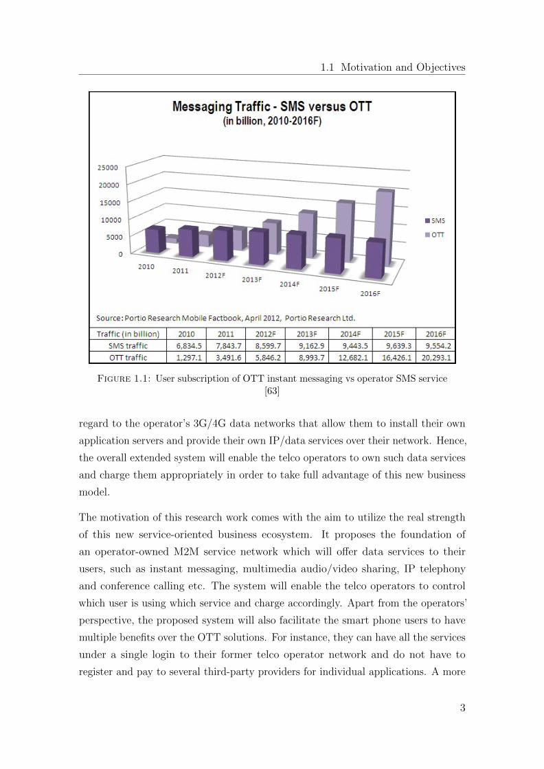
Figure 1.1 depicts the results of a research study [72] by Portio Research, which
compares how smart phone users consume the OTT instant messaging applications
versus the legacy telco SMS service. One can see how widely the consumer interest
is shifting towards such OTT applications in future. This is a real threat to the
traditional telco business ecosystem. Although such OTT applications generate
much multimedia traffic over the operator network which seems to be a benefit
for the operators, the revenue they generate from the data contracts is much less
compared to the extra load over the network by these applications. Therefore, they
require somehow a sophisticated control over this traffic that enables them either
to block it or to charge it properly as per load to the network. Some architectural
advances are proposed by 3GPP (The 3rd Generation Partnership Project) in this
2
1.1 Motivation and Objectives
Figure 1.1: User subscription of OTT instant messaging vs operator SMS service[63]
regard to the operator’s 3G/4G data networks that allow them to install their own
application servers and provide their own IP/data services over their network. Hence,
the overall extended system will enable the telco operators to own such data services
and charge them appropriately in order to take full advantage of this new business
model.
The motivation of this research work comes with the aim to utilize the real strength
of this new service-oriented business ecosystem. It proposes the foundation of
an operator-owned M2M service network which will offer data services to their
users, such as instant messaging, multimedia audio/video sharing, IP telephony
and conference calling etc. The system will enable the telco operators to control
which user is using which service and charge accordingly. Apart from the operators’
perspective, the proposed system will also facilitate the smart phone users to have
multiple benefits over the OTT solutions. For instance, they can have all the services
under a single login to their former telco operator network and do not have to
register and pay to several third-party providers for individual applications. A more
3
Chapter 1. Introduction
vigilant and important privilege what they can have is the Quality-of-service (QoS)
guarantees from the telco operators. This is the real advantage which OTT providers
cannot provide to their customers because they are unable to control the network
itself. On the other hand, the operators can have full control over the network
resources, and hence, are able to apply different QoS schemes and charging policies
for different types of customers and services.
Besides the business point of view, the long distance wireless network coverage is a
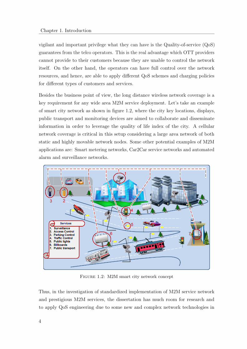
key requirement for any wide area M2M service deployment. Let’s take an example
of smart city network as shown in figure 1.2, where the city key locations, displays,
public transport and monitoring devices are aimed to collaborate and disseminate
information in order to leverage the quality of life index of the city. A cellular
network coverage is critical in this setup considering a large area network of both
static and highly movable network nodes. Some other potential examples of M2M
applications are: Smart metering networks, Car2Car service networks and automated
alarm and surveillance networks.
Figure 1.2: M2M smart city network concept
Thus, in the investigation of standardized implementation of M2M service network
and prestigious M2M services, the dissertation has much room for research and
to apply QoS engineering due to some new and complex network technologies in
4
1.3 Dissertation Contribution
the LTE and IMS system. The real target of this research is to investigate how
to efficiently utilize the cellular network resources in order to enhance the overall
multimedia streaming experience comparable to the high-speed broadband networks
(cable, DSL).
1.2 Dissertation Contribution
This dissertation is an extension of the research work by Aijaz[9] and Gehlen[52],
which mainly lays the architectural design of a mobile server platform and P2P
mobile web services. Without focusing much from the cellular network perspective,
the former research was aimed for wireless networks in general, such as WLAN,
WiFi networks. However, the major contribution of this dissertation is to bring the
existing knowledge of the mobile service layer research to practice into the cellular
network world. Following is a list of some key contributions of this research work :
� The dissertation introduces a novel concept of Mobile Application Servers
(Mob-ASs) in the operator LTE / IMS network running on mobile devices.
Like other Application Servers in the IMS network, a MobAS has the ability
to register itself as a mobile host through standardized interfaces proposed by
3GPP.
� Based on the Mob-AS platform, the dissertation implements a M2M service
network for LTE-Evolved Packet Core (LTE-EPC).
� The M2M services like multimedia instant messaging and real-time audio video
streaming are developed for Mob-AS platform, which are fully compatible to
work with Ericsson IMS and Fraunhofer OpenIMS, OpenEPC testbeds.
� In order to address the QoS concerns, the dissertation introduces a QoS
framework for Mob-AS platform that fulfills the requirements of 3GPP Policy
and Charging Control (PCC) mechanism.
� The dissertation extensively evaluates the behavior of the system based on
user classifications and service types.
5
Chapter 1. Introduction
1.3 Structure of Dissertation
Chapter 2 provides a brief history of the cellular data networks and their services.
Without focusing on complex network and architectural details, the chapter gives
a quick overview how evolution took place in the packet core domain of a mobile
cellular system that enabled it to evolve from a traditional circuit switching to the
all-IP network.
Chapter 3 introduces a novel concept of Mobile Application Server as a foundation
of M2M service networks in the cellular world. The chapter first presents the
potential challenges that can be faced while realizing an M2M service network over
a cellular operator network. Then, it provides the details how an existing Mobile
Server Platform can be extended and utilized to enable M2M communications over
the operator IMS/LTE network.
Chapter 4 enfolds the design and implementation of M2M messaging framework of
the Mobile Server Platform. The chapter describes how M2M text messaging and
multimedia file sharing is realized in a service oriented fashion over the operator
IMS network. Furthermore, the chapter provides the performance evaluation of the
newly implemented services.
Chapter 5 presents the design and implementation of M2M multimedia streaming
framework of the Mobile Server Platform. The chapter describes how M2M multi-
media messaging streaming is realized in a service oriented fashion over the operator
IMS network. Furthermore, the chapter provides the performance evaluation of the
newly implemented services.
Chapter 6 presents the QoS framework of the Mobile Server Platform. The chapter
enfolds how the proposed QoS framework operates in user registration, session
establishment and multimedia delivery phase to provide an end-to-end QoS control.
A promising feature of the proposed framework is to allow the cellular operators to
employ QoS control based on the user profiles classification. Hence, a systematic
approach is adopted to study the behavior of a video streaming prototype based on
different network settings and various user profiles.
Chapter 7 summarizes the complete dissertation work and presents a conclusion
at the end.
6
Chapter 2
Evolution of cellular data
networks
The mobile phones are not associated with communication only; in fact they are
performing many more everyday jobs other than communication. However, the
history of mobile phones is quiet fascinating. The basic telephony was first introduced
in 1876 by Alexandar Graham Bell. Equipped with basic telephony, the early phones
were large and heavy in size as one’s forearms and some even came with large antenna
like a cordless phone. At that time, the phones were just like two-way radios that
allowed people to communicate for emergency services only.
The history of wireless phones starts back from 1908 when a US Patent was presented
in Kentucky for wireless telephones. In 1940, the engineers at AT&T first time
introduced the concept of division of a wider base station area into smaller cells. In
early planning, powerful base stations were utilized to cover a wide area without
dividing into smaller cells. Then an era of smart phones appeared in 1993 when the
first public smart phone was introduced by IBM and BellSouth. They are equipped
with loads of attractive features and capabilities as well as ultra-thin and tech-savvy
as compared to their predecessors.
This chapter provides a brief history of the cellular data networks and their services.
Without focusing on complex network and architectural details, the chapter gives
a quick overview how evolution took place in the packet core domain of a cellular
7
Chapter 2. Evolution of cellular data networks
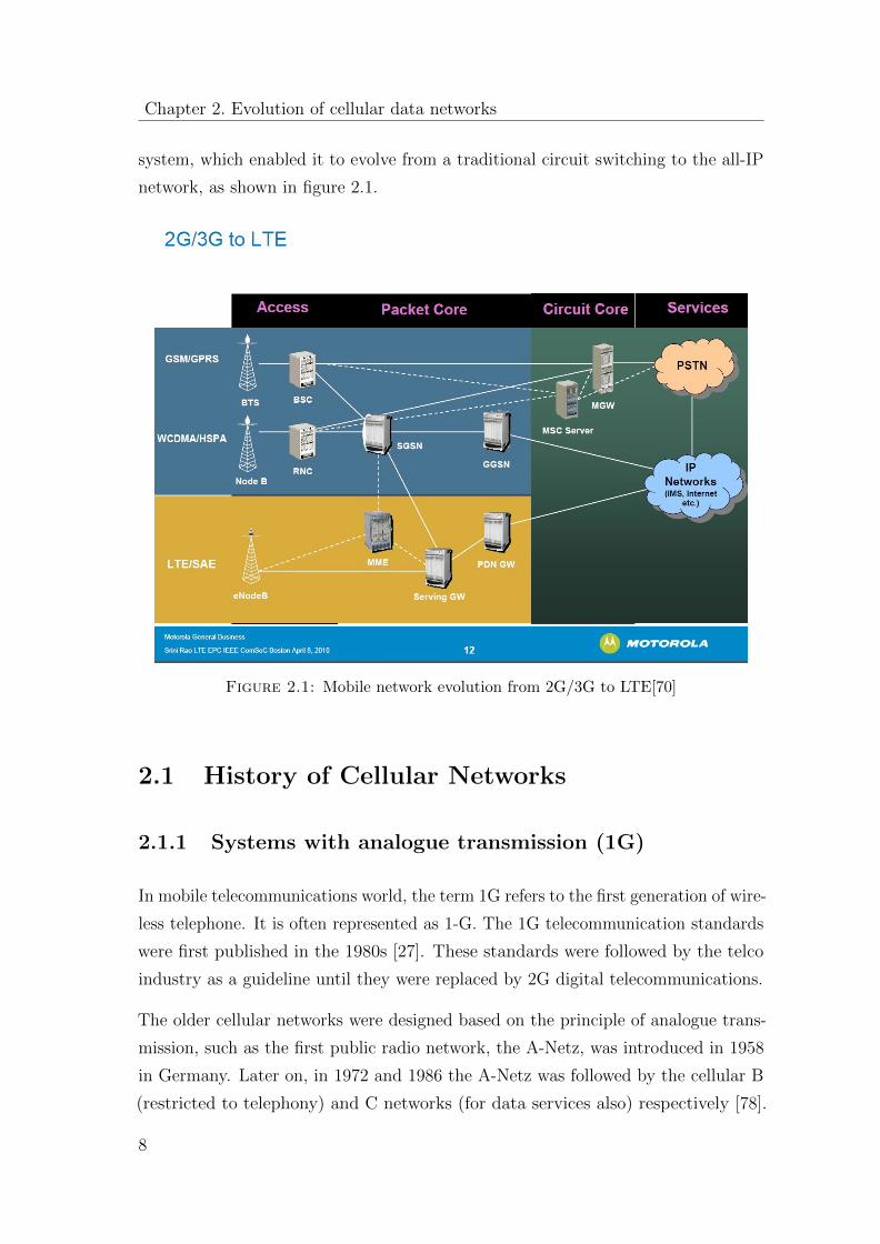
system, which enabled it to evolve from a traditional circuit switching to the all-IP
network, as shown in figure 2.1.
Figure 2.1: Mobile network evolution from 2G/3G to LTE[70]
2.1 History of Cellular Networks
2.1.1 Systems with analogue transmission (1G)
In mobile telecommunications world, the term 1G refers to the first generation of wire-
less telephone. It is often represented as 1-G. The 1G telecommunication standards
were first published in the 1980s [27]. These standards were followed by the telco
industry as a guideline until they were replaced by 2G digital telecommunications.
The older cellular networks were designed based on the principle of analogue trans-
mission, such as the first public radio network, the A-Netz, was introduced in 1958
in Germany. Later on, in 1972 and 1986 the A-Netz was followed by the cellular B
(restricted to telephony) and C networks (for data services also) respectively [78].
8

2.1 History of Cellular Networks
Table 2.1 presents some other details of these networks and a comparison with other
analogue systems deployed in Scandinavia (Scand), Great Britain (GB) and USA.
In 1979, Nippon Telegraph and Telephone (NTT) launched an automated cellular
network, 1-G in Japan [27]. This was a first commercial project by a telecommuni-
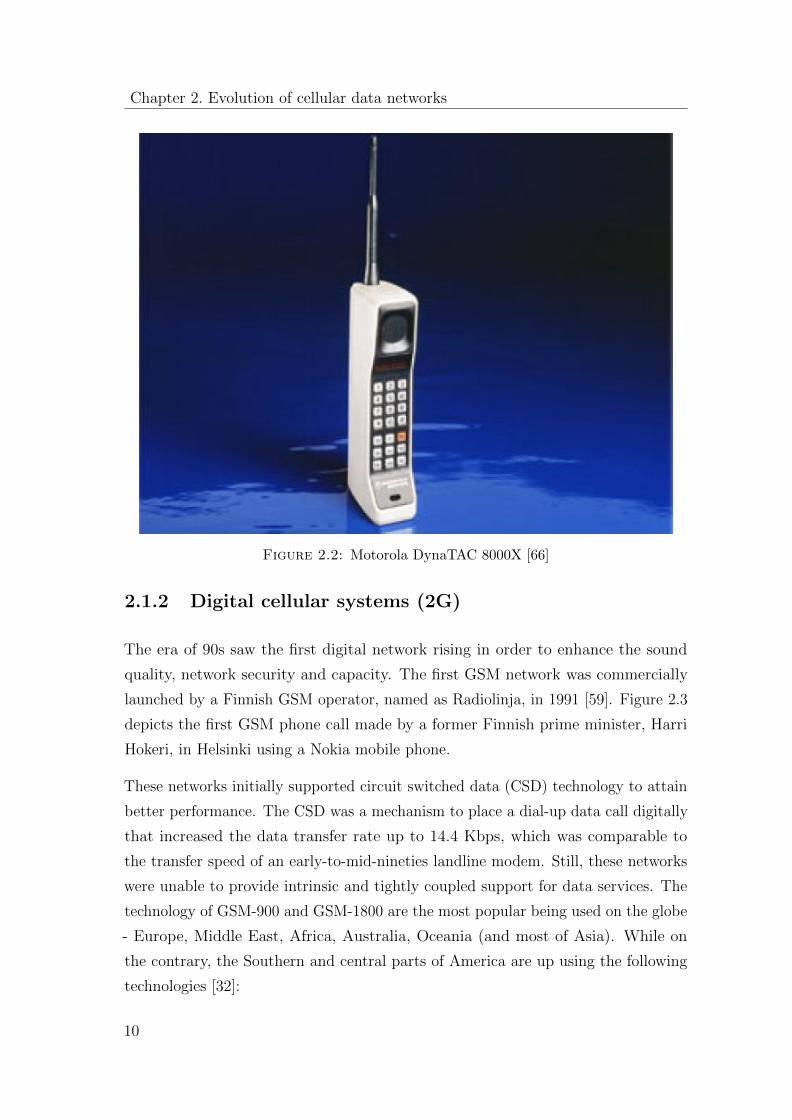
cation authority at that time. Likewise, the first 1G project was started in 1983 by
Ameritech in Chicago. The first ever mobile phone of Motorala’s DynaTac series was
used in this project. Figure 2.2 depicts the first portable cellular phone by Motorola
that was approved by Federal Communications Commission (FCC) on September 21
1983.
In 1990, numerous eminent cell phones such as the Motorola DynaTAc Analog
AMPS were ultimately outdated and replaced by Digital AMPS (D-AMPS). Since
the service was outdated therefore it resulted into the down fall and by 2008, AMPS
service was shut down by most of the American carriers.
Parameter C450 NMT450 NMT900 TACS E-TACS AMPSCountry Germany Scand Scand GB GB USAStandard DBP Telekom CRAG CRAG FCCIntroduced in 1985 1981 1986 1984 1983UplinkMHz 450.3-454.74 453-457.5 890-915 890-915 872-905 824-849DownlinkMHz 461.3-465.74 463-467.5 935-960 935-960 917-950 869-894Channelspacing KHz 20 25 20 25 12.5 25 25 30Duplex rangeMHz 11 10 45 45 45 45Access method FDMA FDMA FDMA FDMA FDMA FDMAModulation FSK FFSK FFSK PSK PSK PSKMAH Yes No No No No NoCell diameterKm 15-40 2-20Frequencies 222 180 220 1000 1000 1320 833Data serviceskbits/s 2.4 2.4Traffic capacityErl/km2 14 14 12
Table 2.1: An overview of analogue cellular mobile radio [78]
9
Chapter 2. Evolution of cellular data networks
Figure 2.2: Motorola DynaTAC 8000X [66]
2.1.2 Digital cellular systems (2G)
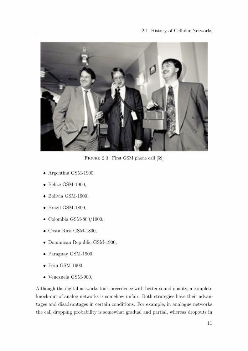
The era of 90s saw the first digital network rising in order to enhance the sound
quality, network security and capacity. The first GSM network was commercially
launched by a Finnish GSM operator, named as Radiolinja, in 1991 [59]. Figure 2.3
depicts the first GSM phone call made by a former Finnish prime minister, Harri
Hokeri, in Helsinki using a Nokia mobile phone.
These networks initially supported circuit switched data (CSD) technology to attain
better performance. The CSD was a mechanism to place a dial-up data call digitally
that increased the data transfer rate up to 14.4 Kbps, which was comparable to
the transfer speed of an early-to-mid-nineties landline modem. Still, these networks
were unable to provide intrinsic and tightly coupled support for data services. The
technology of GSM-900 and GSM-1800 are the most popular being used on the globe
- Europe, Middle East, Africa, Australia, Oceania (and most of Asia). While on
the contrary, the Southern and central parts of America are up using the following
technologies [32]:
10
2.1 History of Cellular Networks
Figure 2.3: First GSM phone call [59]
� Argentina GSM-1900,
� Belize GSM-1900,
� Bolivia GSM-1900,
� Brazil GSM-1800,
� Colombia GSM-800/1900,
� Costa Rica GSM-1800,
� Dominican Republic GSM-1900,
� Paraguay GSM-1900,
� Peru GSM-1900,
� Venezuela GSM-900.
Although the digital networks took precedence with better sound quality, a complete
knock-out of analog networks is somehow unfair. Both strategies have their advan-
tages and disadvantages in certain conditions. For example, in analogue networks
the call dropping probability is somewhat gradual and partial, whereas dropouts in
11
Chapter 2. Evolution of cellular data networks
digital networks are quite sudden and frequent in bad network conditions. In addi-
tion to the GSM protocol, 2G also utilizes various other digital protocols, including
CDMA (Code division multiple access), TDMA (Time division multiple access),
iDEN (Integrated Digital Enhanced Network) and PDC (Personal Digital Cellular).
GSM is based on TDMA/FDMA (Frequency division multiple access).
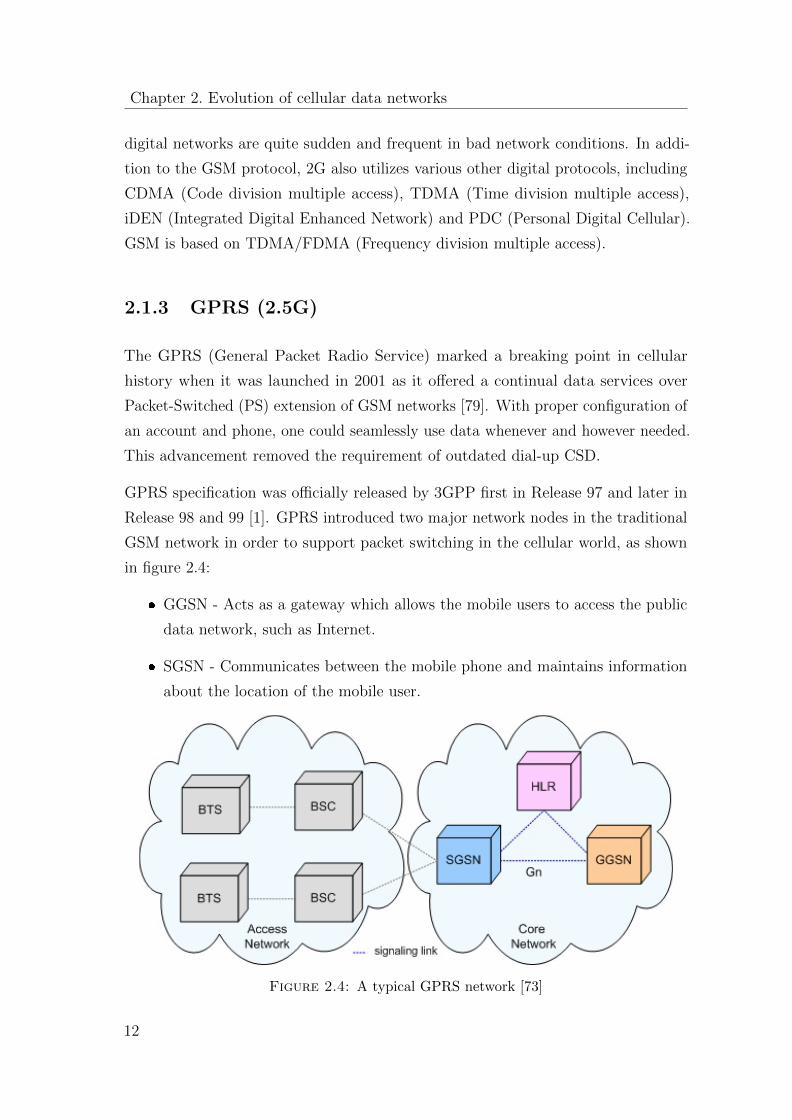
2.1.3 GPRS (2.5G)
The GPRS (General Packet Radio Service) marked a breaking point in cellular
history when it was launched in 2001 as it offered a continual data services over
Packet-Switched (PS) extension of GSM networks [79]. With proper configuration of
an account and phone, one could seamlessly use data whenever and however needed.
This advancement removed the requirement of outdated dial-up CSD.
GPRS specification was officially released by 3GPP first in Release 97 and later in
Release 98 and 99 [1]. GPRS introduced two major network nodes in the traditional
GSM network in order to support packet switching in the cellular world, as shown
in figure 2.4:
� GGSN - Acts as a gateway which allows the mobile users to access the public
data network, such as Internet.
� SGSN - Communicates between the mobile phone and maintains information
about the location of the mobile user.
Figure 2.4: A typical GPRS network [73]
12
2.1 History of Cellular Networks
The service was envisaged to offer faster data rates than GSM, with a theoretical
downlink speed of up to 171 Kbps [42]. The innovation of GPRS came at the
right time when people really started checking their e-mails regularly. It was a
transformation which was warmly greeted by the people all over the globe. The major
players in the US market like AT&T Wireless, Cingular, and Voice Stream (later
T-Mobile USA) and every major GSM operator in the world, deployed the service.
However, this breakthrough in GSM technology did not provide a generational notch.
Soon after GPRS launch, the UN’s International Telecommunications Union put
together its IMT-2000 standard which specified a true 3G technology, requiring
stationary speeds of 2 Mbps and mobile speeds of 384 Kbps [83]. Those specifications
were tough to meet by GPRS as it couldn’t meet these benchmarks even on its best
day.
Subsequently, 2.5G technology was used to bridge between 2G and 3G wireless
technologies. 2G is primarily referred to describe those evolved technologies that
were first considered as being 2G. Unlike 2G and 3G, which have been officially
defined as wireless standards by the International Telecommunication Union (ITU),
2.5G has not been recognized by ITU and thus was created only for the purpose of
marketing. This is how GPRS got sandwiched between 2G and 3G technology as it
was better than 2G but not good enough to be called as 3G. Had ITU not specified
3G, 2.5G might have earned the right to be called as 3G. But now, it seems to just
be the first of many generational schemes over the next decade.
2.1.4 EDGE (2.5/2.7G)
EDGE also referred as 2.75G is a data connectivity service faster than GPRS
(sometimes called 2.5G) but slower than 3G networks. The fact of the matter is that
the EDGE has been officially recognized as 3G technology. It is pertinent to mention
here that the typical EDGE implementations generally do not obtain 3G data
rates, thus, leading people to call it 2.75G. As compared to ordinary GSM/GPRS
connection, EDGE delivers threefold increase in capacity and performance due to
its higher bit-rates per radio channel through sophisticated methods of coding and
transmitting data.
13
Chapter 2. Evolution of cellular data networks
With evolved EDGE continuation in Release 7 of the 3GPP standard, it provides a
reduced latency and more than doubled performance to complement High-Speed
Packet Access (HSPA). Peak bit-rates of up to 1 Mbps and typical bit-rates of 400
Kbps can be expected. EDGE enhancement of circuit switched data communication
is called ECSD (Enhanced Circuit Switched Data). The purpose of ECSD is to
increase data transmission rates and to update the existing applications such as high-
speed circuit switched data (HSCSD) for EDGE modulation in the radio interface
[68]. EDGE enhancement of packet switched data communication is called EGPRS
(Enhanced GPRS). BTS and MS devices must be EDGE capable in GSM/GPRS
system architecture. For the same purpose, the BTS units must be enhanced with
EDGE Transceiver Units (EDGE TRU) due to the higher data communication rates.
Only in case of BSS, GPRS and EGPRS have different protocols and behavior.
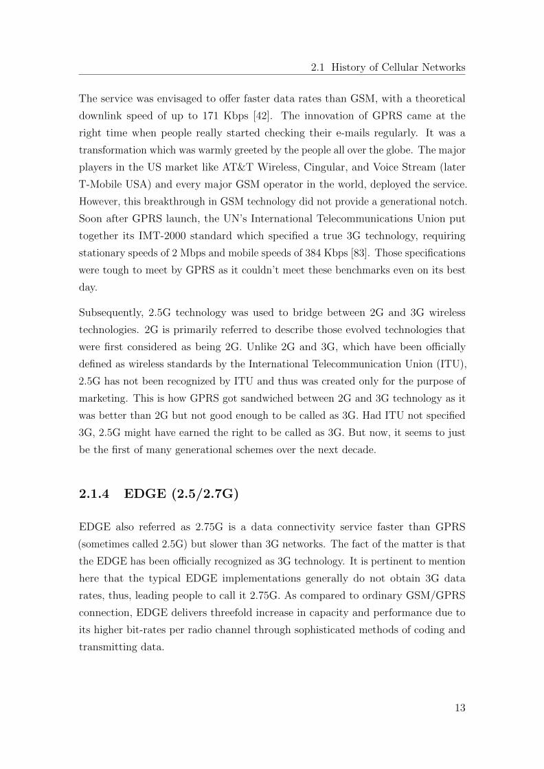
In Figure 2.5, user plane protocol architecture is depicted where EGDE modified
protocols are BSSGP, RLC, MAC and GSM RF. The rest of the protocols are not
influenced by the introduction of EDGE.
Figure 2.5: Protocols introduced by EDGE in GPRS [33]
2.1.5 UMTS (3G)
The term (UMTS) refers to Universal Mobile Telecommunications System and
likewise term 3G refers to the third-generation in mobile telecommunications world.
14
2.1 History of Cellular Networks
It is a third generation mobile cellular system for networks based on the GSM
standard. 3G mobile communications standards allow mobile phones, hand-held
devices, and computers to access the Internet wirelessly. 3G provides a wider range
of services and advances network capacity over earlier 2G networks. It also boosts
the rate of information transfer known as spectral efficiency. The telephony has
received a wider area and more range, while video and broadband data transfers
have also been affected much faster.
It is more complicated to forecast the expected usage of different services for different
types of traffic. Video requires high data usage in comparison with E-mail. For
example in real-time voice call, audio streaming requires high data usage. It is just
like providing dedicated channel for circuit-switched voice but with much greater
bandwidth demands.
The first 3G network offered for commercial use was successfully launched in Japan
and South Korea [76]. The initial commercial launch of 3G was also done by NTT
DoCoMo in Japan. Subsequently, British Telecom in the UK and Monet Mobile
Networks in US followed suit. Most countries had implemented the 3G technology
by 2007.
3G is about four times faster than the old 2G standards. With initial speed of
around 200 Kbps and steady transformation of the technological innovations saw
maximum speed of up to 7.2 Mbps. The download speed of 3G network is about
14.4 MB/s and upload speed is 5.8 Mbps. The minimum speed for a stationary
user is 2 Mbps, whereas a user in a moving vehicle can expect 348 Kbps. Some
distinctive services associated with 3G are: Voice telephony, Broadband wireless
data, Mobile video, Mobile e-commerce, Location-based services, Mobile gaming
and Audio-on-demand.
The 3G network uses a different frequency than 2G. This eventually forced many
operators to build entirely a new infrastructure and obtain additional licenses. Based
on these reasons, countries like China and Indonesia deliberately chose to hold back
the network from its citizens for many years.
15
Chapter 2. Evolution of cellular data networks
2.1.6 LTE (4G)
LTE is a short form for Long-Term Evolution, which is usually known as 4G LTE.
It is a radio and wireless broadband technology to support high-speed data for
mobile phones and handheld devices. 4G LTE allows operators to attain higher peak
throughputs than HSPA+ in higher spectrum bandwidth.
In 2004, 3GPP initiated work on LTE and a completed 3GPP Release 8 in March
2009 [17]. The first LTE network was commercially launched in December 2009 by
TeliaSonera in Norway. In last few years, 4G LTE has brought epic advances in the
fields of education, health, transportation, and at enterprise level.
4G LTE is one of the several competing 4G standards that offers Ultra Mobile
Broadband (UMB) access to the web from mobile devices such as smart phones,
laptop computers with wireless modems. It supports not only quicker access and
ultra-fast speed to the web from mobile devices, but also opens up new opportunities
for video conferencing, streaming high-definition videos and cloud computing.
The core objective of 4G LTE networks is to sustain higher data rates, high per-
formance radio access technology, abridge the network architecture by utilizing
all packets that eventually reduce network latency. Since 4G LTE has a scalable
bandwidth, so this allows operators to easily migrate their networks and users from
HSPA to LTE over the period of time. LTE is designed in such a manner that
supports voice in the packet domain. It integrates the best in a given line of radio
techniques to achieve higher performance levels that will not be attainable through
with CDMA approaches, essentially in larger channel bandwidths.
In integrated networks, LTE systems coexist with 3G and 2G systems in the same
way as 3G coexists with 2G systems. Multi-mode devices will function across
LTE/3G or even LTE/3G/2G depending upon market situation. Below mentioned
are some unique capabilities of the LTE network: [17]
� Downlink peak data rates up to 326 Mbps with 20 MHz bandwidth.
� Uplink peak data rates up to 86.4 Mbps with 20 MHz bandwidth.
� Operation in both TDD and FDD modes.
16
2.2 State of the Art Technologies
� Scalable bandwidth up to 20 MHz, covering 1.4 MHz, 3 MHz, 5 MHz, 10 MHz,
15 MHz, and 20 MHz in the study phase.
� Increased spectral efficiency over Release 6 HSPA by two to four times.
� Reduced latency, up to 10 milliseconds (ms) round-trip times between user
equipment and the base station, and to less than 100 ms transition times from
inactive to active source.
2.2 State of the Art Technologies
The above section provides a general overview of the cellular network technologies
used in the past. Hence, this section presents some more specific details of the state
of the art tools and technologies that are currently being practiced in the telecom
industry and academia as well as relevant to understand the technical details of this
research work in particular.
The state of the art discussion is divided into three different streams : 1) Packet core
services and solutions based on IMS and LTE ecosystem 2) Mobile Server Platform
3) Quality of Service in Mobile networks
The first stream explains how data services are deployed in the IMS/LTE system and
how policy and charging control works for multimedia applications. Then, it gives
an overview of the industrial standards and solutions to deploy voice and messaging
services over the cellular operator networks using the IMS and related technologies.
The second stream discusses the mobile server platform research and presents the
state of the art in this regard. The third stream focuses on the QoS control of the
multimedia applications deployed in the mobile networks. It highlights the QoS
issues and presents the proposed solutions both from academia and industry.
2.2.1 LTE - EPC and 3GPP PCC Architecture
System Architecture Evolution, or SAE, is identical with Evolved Packet Core, or
EPC. SAE/EPC is defined by 3GPP in Release 8 [7] as a completely new core
network with a flatter all-IP architecture. It is a low latency packet-optimized
17
Chapter 2. Evolution of cellular data networks
system that supports multiple radio-access technologies, with the assumption that
the system will support all services including voice in the packet-switched domain
[16]. The radio access technologies supported by EPC include 3GPP networks,
such as GERAN (radio access network of GSM/GPRS) and UTRAN (radio acces
network of UMTS-based technologies), as well as some non-3GPP networks, such as
WiMax, cdma200, WLAN and fixed networks. The non-3GPP networks are further
categorized into ”trusted” and ”untrusted” networks. However, 3GPP leaves this
decision to network operators to specify which non-3GPP networks are treated as
trusted or untrusted.
The 3GPP’s aim is to establish an access-agnostic policy control framework, with the
objective of introducing a standard for quality of service and policy mechanisms for
multi-vendor deployments which allow the operators to offer service and subscriber
differentiation. The standard set by 3GPP elaborates about creating transmission
paths between the external packet data network (PDN) and the user equipment (UE)
with distinct QoS. Bearer Model has been introduced by 3GPP to implement QoS.
A bearer is a logical channel used for a service with well defined QoS parameters.
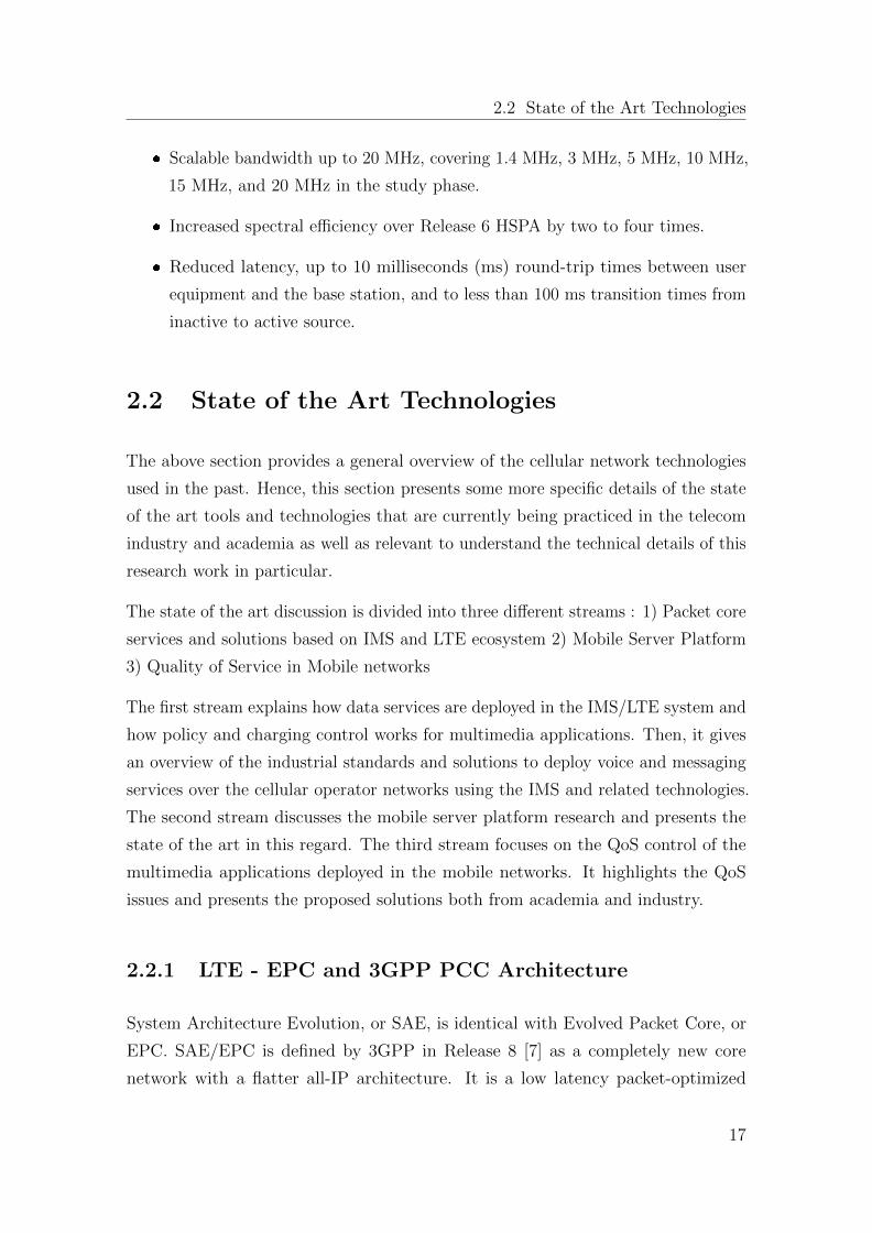
Figure 2.6: LTE - Evolved Packet Core [14]
Figure 2.6 presents a basic architecture of LTE-EPC comprised of various network
elements: the Mobility Management Entity (MME), the Serving Gateway (SGW),
the Packet Data Network Gateway (PDN-GW) and the Policy controller (PCRF).
As depicted, the architecture supports provisioning of IP communications and
various multimedia services by connecting to some service delivery platforms (e.g.,
Application Servers in the IMS).
18
2.2 State of the Art Technologies
1. Mobility Management Entity (MME) The MME deals with the control
plane signaling of LTE EPC architecture. It is responsible for initiating
paging and authentication of the UE towards the central user database. It is
a termination point of Non Access Strartum (NAS) signaling from the UE,
which is used for initial attachment, authentication and service requests etc.
Among its other duties, the MME is also responsible for UE authorization to
Public Land Mobile Network (PLMN), enabling roaming restrictions and load
balancing between SGWs etc.
2. Serving Gateway (SGW) The Serving Gateway (SGW) is a network entity
that deals with the transportation of IP data traffic between the UE and the
external networks. In other words, it is a gateway that serves the UE by routing
the incoming and outgoing IP traffic. Moreover, it is responsible for acting as
a mobility anchor-point for handovers with the neighbouring eNodeB’s, and
between LTE and other 3GPP technologies (e.g., 2G/3G systems).
3. Packet Data Network Gateway (PDN-GW) The PDN GW (also known
as PGW) is the point of interconnect between the EPC and the external
packet data network. The UE may simultaneously connect to more than one
PDN-GWs to access multiple packet data networks.
4. Policy and Charging Rules Function (PCRF) Numerous nodes in the
LTE and EPC access play a significant role in implementing QoS and policy
management. The policy server (known as PCRF) is the key figure out of
them. The service session-level policy decisions are produced with the help
of PCRF which tend to work by taking the obtainable network information
and operator configured policies. The decisions which are also called the PCC
(Policy and Charging) rules are then further sent to the policy and charging
enforcement function (PCEF) which is found in the PDN-GW. The PCEF
imposes the policy decisions by introducing bearers, mapping the service data
flows to the bearers and executing traffic policies. [8]. The PDN-GW maps the
bearers against the underlying transport network. The transport network at
times uses the MPLS but normally it is based on the Ethernet. The standard
IP QoS techniques are used by the transport network as it is ignorant of the
bearer concept.
19
Chapter 2. Evolution of cellular data networks
The end-to-end QoS and policy enforcement is managed with the help of
eNodeB. eNodeB is the radio base station in LTE. Following are the three
main functions of eNodeB: [8]
� Makes the uplink and downlink rate policing
� Defines RF radio resource scheduling
� Uses ARP for the allocation of bearer resources
The radio resource scheduling algorithms in eNodeB have a huge influence on the
overall network performance as well as on the quality of service. Mobile network
equipment manufacturers (NEMs) have to consider that network operators have a
lot of chances to connect their eNodeB products to competitor’s products. The UE
has a key role to play in the uplink direction. The bearer and service data flows
mapping is done with its help.
2.2.2 IP Multimedia Subsystem (IMS)
The IMS defines a generic framework for enabling the convergence of voice, video and
data communications over IP-based infrastructure using Session Initiation Protocol
(SIP) [53]. It was originally introduced to evolve 3G / UMTS data core network by
3GPP (release 5) to enable IP multimedia communications based on widely adopted
Internet standards and protocols defined by the Internet Engineering Task Force
(IETF), such as SIP, IPv6 and Diameter [44]. Later in subsequent releases 6 and
7, the IMS specification was further refined and maintained as a part of 3G packet
core network [2]. In release 8, the IMS is adopted as a application layer standard
with the introduction of LTE-Evolved Packet Core (LTE - EPC).
The IMS actively plays its role in the control signaling part of IP multimedia
communications, leaving the PS core network to provide transport for the data
transmission. In other words, the IMS is not aimed to produce or bring new IP
multimedia services in the operator network but to facilitate the provisioning of such
services with the necessary QoS control, charging, routing and messaging mechanisms
etc [52]. Subsequently, the network operators have more control over the IP services
running over their network.
20
2.2 State of the Art Technologies
Prof. Dr. M. Jarke
Lehrstuhl Informatik 5
(Information Systems)
RWTH Aachen
Muzzamil Aziz Chaudhary
September 14 , 2011
Slide 15
IM SSF OSA AS SIP AS
HSS SLF
S-CSCF I-CSCF
P-CSCF
PSTN Gateway
MRFC
MRFP
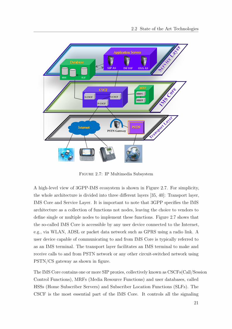
Figure 2.7: IP Multimedia Subsystem
A high-level view of 3GPP-IMS ecosystem is shown in Figure 2.7. For simplicity,
the whole architecture is divided into three different layers [35, 40]: Transport layer,
IMS Core and Service Layer. It is important to note that 3GPP specifies the IMS
architecture as a collection of functions not nodes, leaving the choice to vendors to
define single or multiple nodes to implement these functions. Figure 2.7 shows that
the so-called IMS Core is accessible by any user device connected to the Internet,
e.g., via WLAN, ADSL or packet data network such as GPRS using a radio link. A
user device capable of communicating to and from IMS Core is typically referred to
as an IMS terminal. The transport layer facilitates an IMS terminal to make and
receive calls to and from PSTN network or any other circuit-switched network using
PSTN/CS gateway as shown in figure.
The IMS Core contains one or more SIP proxies, collectively known as CSCFs(Call/Session
Control Functions), MRFs (Media Resource Functions) and user databases, called
HSSs (Home Subscriber Servers) and Subscriber Location Functions (SLFs). The
CSCF is the most essential part of the IMS Core. It controls all the signaling
21
Chapter 2. Evolution of cellular data networks
information to and from IMS terminals and Application Servers(ASs). A CSCF
can be one of the three different types [36, 40]: P-CSCF (Proxy-CSCF), I-CSCF
(Interrogating-CSCF), S-CSCF (Serving-CSCF).
1. Proxy Call Session Control Function (P-CSCF) The P-CSCF claims to
provide a reliable transmission of the SIP signalling. It is originally a SIP proxy
which acts as the main contact point that is provided to the user terminals by
the IMS domain. P-CSCF supports the SIP signal compression and plays a
significant role in exposing the IMS Emergency Services.
2. Interrogating Call Session Control Function (I-CSCF) It is the princi-
pal point of contact in the home network, which acts as a SIP Proxy located
at the edge of the network. I-CSCF helps in the discovery of S-CSCF where
the user is trying to register. The SIP request is then further directed to its
allocated S-CSCF.
3. Serving Call Session Control Function (S-CSCF) S-CSCF acts as the
kernel of the IMS system. It has the liabilities, such as session maintenance,
routing and translation, charging and transmission of information. It also
assists in user authentication and in getting the user’s service profile.
4. Home Subscriber Server (HSS) It is a centralized database containing the
information about all IMS users as well as subscribers. Network units handling
calls and sessions work on the basis of data provided to them by HSS. If a new
user is registered in the IMS domain, the user profile is accessed via HSS and
is made available to the CSCF. A Subscriber Location Function (SLF) solves
the problem of the location of the subscription data in case of multiple HSS.
5. Breakout Gateway Control Function (BGCF) The BGCF is a logical
unit which is part of the IMS network. It is responsible for making decisions
about the routing of the telephony sessions initiated within the IMS network
and which are intended for circuit switched networks (PSTN or other wireless
networks).
6. Media Resource Function (MRF) The Media Resource Function (MRF),
as the name implies, is there for providing media services in the home network.
It is responsible for the management and processing of media streams which
includes voice, text-to-speech conversion and video etc. Every MRF available
22
2.2 State of the Art Technologies
in the network may be provided by a Media Resource Function Controller
(MRFC), a signalling node which facilitates the S-CSCF as a SIP User Agent.
7. Session Border Controller (SBC) The SBC is also known as the Border
Control Function. SBC is an IP-to-IP gateway which is deployed on the border
between an operator’s own IMS network and other IMS networks. It is a
Network to Network interface (NNI). Broadband access to the IMS by UEs
can be achieved with the help of the policy enforcement functionality and the
P-CSCF; they can team-up to implement such a Session Border Controller
which supports the User-to-Network Interface (UNI).
8. Media Gateway Control Function (MGCF) It is the vital node of the
PSTN gateway. It controls the media resources involved in the flow of traffic
between networks having variant types of media. It classically works with an
IP based network along with Time Division Multiplexing (TDM) network. Its
interaction with the call and session control functions is based on the Session
Initiation Protocol (SIP). Also, it collaborates with the control plane of the
GSTN using ISUP and nevertheless, with the Media Gateway using the H.248
protocol.
9. Media Gateway (MGW) The Media Gateway Control Function (MGCF)
controls the Media Gateway (MGW) with the help of H.248 protocol. It helps
with the media flows among various networks. It deals with a number of differ-
ent formats which are there for media transportation including RTP/UDP/IP,
TDM and video and voice transcoding.
10. IMS Application Servers SIP application server can host several services
or it may as well be dedicated for a single service. To provide the user with
an unmatched unified user experience, IMS facilitates to combine services
from various application servers. Centralization, rapid network access and
the simplicity of the application development process are some of the core
advantages of the SIP application server. The updates as well as the upgrades
are more reliable now due to the centralization of the business logic on fewer
SIP application servers. There is no chance of getting an upgrade that belongs
to some older version or other similar problems.
23
Chapter 2. Evolution of cellular data networks
2.2.3 IMS/LTE based Service Networks
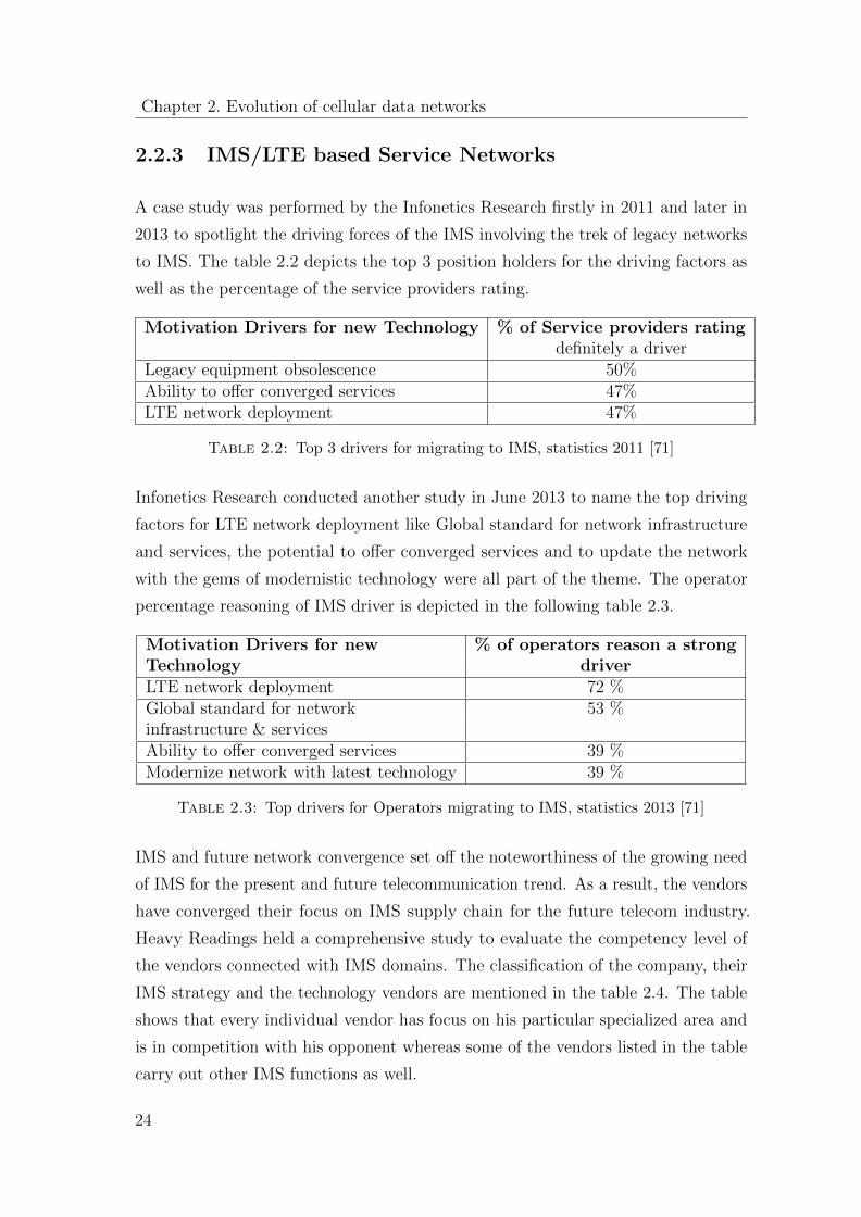
A case study was performed by the Infonetics Research firstly in 2011 and later in
2013 to spotlight the driving forces of the IMS involving the trek of legacy networks
to IMS. The table 2.2 depicts the top 3 position holders for the driving factors as
well as the percentage of the service providers rating.
Motivation Drivers for new Technology % of Service providers ratingdefinitely a driver
Legacy equipment obsolescence 50%Ability to offer converged services 47%LTE network deployment 47%
Table 2.2: Top 3 drivers for migrating to IMS, statistics 2011 [71]
Infonetics Research conducted another study in June 2013 to name the top driving
factors for LTE network deployment like Global standard for network infrastructure
and services, the potential to offer converged services and to update the network
with the gems of modernistic technology were all part of the theme. The operator
percentage reasoning of IMS driver is depicted in the following table 2.3.
Motivation Drivers for new % of operators reason a strongTechnology driverLTE network deployment 72 %Global standard for network 53 %infrastructure & servicesAbility to offer converged services 39 %Modernize network with latest technology 39 %
Table 2.3: Top drivers for Operators migrating to IMS, statistics 2013 [71]
IMS and future network convergence set off the noteworthiness of the growing need
of IMS for the present and future telecommunication trend. As a result, the vendors
have converged their focus on IMS supply chain for the future telecom industry.
Heavy Readings held a comprehensive study to evaluate the competency level of
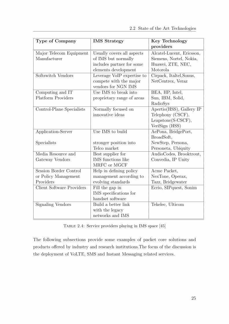
the vendors connected with IMS domains. The classification of the company, their
IMS strategy and the technology vendors are mentioned in the table 2.4. The table
shows that every individual vendor has focus on his particular specialized area and
is in competition with his opponent whereas some of the vendors listed in the table
carry out other IMS functions as well.
24
2.2 State of the Art Technologies
Type of Company IMS Strategy Key Technologyproviders
Major Telecom Equipment Usually covers all aspects Alcatel-Lucent, Ericsson,Manufacturer of IMS but normally Siemens, Nortel, Nokia,
includes partner for some Huawei, ZTE, NEC,elements development Motorola
Softswitch Vendors Leverage VoIP expertise to Cirpack, Italtel,Sonus,compete with the major NetCentrex, Verazvendors for NGN IMS
Computing and IT Use IMS to break into BEA, HP, Intel,Platform Providers proprietary range of areas Sun, IBM, Solid,
RadioSysControl-Plane Specialists Normally focused on Apertio(HSS), Gallery IP
innovative ideas Telephony (CSCF),Leapstone(S-CSCF),VeriSign (HSS)
Application-Server Use IMS to build AePona, BridgePort,BroadSoft,
Specialists stronger position into NewStep, Persona,Telco market Personeta, Ubiquity
Media Resource and Best supplier for AudioCodes, Brooktrout,Gateway Vendors IMS functions like Convedia, IP Unity
MRFC or MGCFSession Border Control Help in defining policy Acme Packet,or Policy Management management according to NexTone, Operax,Providers evolving standards Tazz, BridgewaterClient Software Providers Fill the gap in Ecrio, SIPquest, Sonim
IMS specifications forhandset software
Signaling Vendors Build a better link Tekelec, Ulticomwith the legacynetworks and IMS
Table 2.4: Service providers playing in IMS space [45]
The following subsections provide some examples of packet core solutions and
products offered by industry and research institutions.The focus of the discussion is
the deployment of VoLTE, SMS and Instant Messaging related services.
25
Chapter 2. Evolution of cellular data networks
2.2.3.1 Ericsson VoLTE portfolio
Ericsson is facilitating the telecommunication industry with various types of services,
nevertheless is one of the leading vendors of IMS and VoLTE solutions as well.
Reports inform that more or less 70% of the mobile network operator’s revenue is
produced from the voice and SMS services. Also, it is highly anticipated that voice
service would be the most treasured service in the LTE and NGN networks.
LTE, RAN, EPC, IMS, other Data management and global services are all part
of Ericsson VoLTE solution. It is based on 3GPP standards. Below mentioned
categories portray a picture of Ericsson end-to-end VoLTE solution [41]:
1. Mobile
� IMS and Multimedia Telephony Application Server (MTAS)
� Mobile Softswitch solution
� Subscriber Data management
2. Voice support in EPC
� Mobility management entity (SGSN-MME) is an upgraded version
of SGSN for EPC. It supports multi-access, GSM, WCDMA, LTE and
interworks with WiFi and CDMA.
� Mobile Packet Gateway (GGSN-MPG) is an additional Gateway
entity for large network operators with an installed base of GGSNs, also
having a large number of subscribers.
� PCRF support
3. Voice support in LTE RAN
� Subscriber device
CSFB (Circuit Switched Fallback) for voice services was used by the operators in the
initial release of LTE smart phones. The CSFB solution was commercially launched
in 21 countries of Asia-pacific, North America and Europe by the end of December
2012. Ericsson is vigorously involved with a chipset vendor for the availability of
26
2.2 State of the Art Technologies
VoLTE based phones. SRVCC (Single Radio Voice Call Continuity) solution is also
being intensely developed and tested by Ericsson. [41]
Diameter Signaling Controller (DSC)
The protocol for the control signaling in LTE and IMS network is known as the
Diameter signaling. However, Diameter signaling is controlled and secured using the
Ericsson DSC. Following are the advantages of DSC [39]:
� Significant reduction of Operational expenditures
� Robust network signaling
� Less vulnerable to IP based attacks
A number of characteristics of the Ericsson DSC product make it out stand in
comparison to the portfolios available in the market. The Diameter protocol triggers
the control signaling which is a very crucial feature in the network. User performance
related features are very important like authentication of the user, charging and
mobility management. They are based on the Diameter protocol and any failure
in this channel would affect the end user. The Ericsson DSC is aimed to provide
scalability and in-service performance for control signaling products and perform
multiple roles, such as: [39]
� The Diameter Agent (DA) controls the messaging between the network
nodes and is also used to route the signals.
� Diameter Edge Agent (DEA) supports the LTE roaming by routing the
signaling messaging between the network elements.
� Diameter Routing Agent (DRA) routes the signaling message for policy
and charging function to the IMS.
The Ericsson DSC addresses a few main scenarios to satisfy the increasing demand
of Diameter signaling [43]:
� Centralized routing
� Overload protection
� LTE roaming support
27
Chapter 2. Evolution of cellular data networks
� Session binding
� Address resolution of nodes
2.2.3.2 Fraunhofer FOKUS OpenIMS and OpenEPC testbed
FOKUS competence center NGNI and TU Berlin -AV established a cutting edge
testbed system for 3GPP EPC known as the OpenEPC. It will assist not only
the industry, but academic institutes (Universities, Research Centers etc.) as well
in developing a real-world working scenarios of the 4G technology. The FOKUS
team has provided number of updates for this test-bed and the version 4 from
May 2013 is under consideration of this research. The interfaces provided in the
version 4 have given support for a lot of different access technologies. The OpenEPC
toolkit is thought to be one of the most advanced and customizable platform for the
fundamental testing of functions of cellular networks [49]. Testing of latest releases
of cellular technologies like GSM, UMTS, HSPA and LTE is supported by OpenEPC.
Following are some of the advantages of the available solutions as a result of the
usage of OpenEPC along with 3GPP LTE Rel.11 [49]:
� The core functional components and reference points specified in 3GPP stan-
dard for the base architecture are part of it.
� Modem and phone testing is supported.
� It facilitates the opportunity to test the integration of LTE-EPC off-the-shelf
2G base stations for GPRS/EDGE, 3G base stations for UMTS/HSPA, 4G
base stations for LTE/LTE Advanced and Wi-Fi.
� Its key characteristics involve the integration of IP Multimedia System (IMS)
(www.openimscore.org) for new Voice-over-LTE (VoLTE) technology.
� The support provided to access the source code under specific licensed condi-
tions.
� All the forthcoming evolutionary concepts like Network Function Virtualization
(NFV), Software Defined Networking (SDN) and Self-Organizing Networks
(SON) are supported.
28
2.2 State of the Art Technologies
The OpenEPC has brought great revolution as a testing environment for mobile
network operators to provide support for testing 3GPP IP based systems like LTE,
HSPA and EDGE along with Wi-Fi (a non-3GPP based system) [49].
VoLTE demonstrator using OpenIMS Core and OpenEPC
The IMS is considered to be the most reliable solution for providing multimedia
services focusing QoS for the end user, and for the VoLTE network. The open source
project of OpenEPC completely supports OpenIMS Core comprising PCRF module
for user policy management.
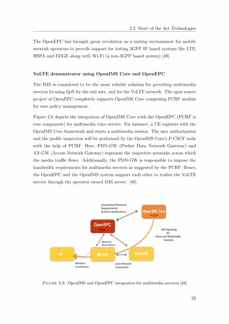
Figure 2.8 depicts the integration of OpenIMS Core with the OpenEPC (PCRF is
core component) for multimedia voice service. For instance, a UE registers with the
OpenIMS Core framework and starts a multimedia session. The user authorization
and the profile inspection will be performed by the OpenIMS Core’s P-CSCF node
with the help of PCRF. Here, PDN-GW (Packet Data Network Gateway) and
AN-GW (Access Network Gateway) represent the respective networks across which
the media traffic flows. Additionally, the PDN-GW is responsible to impose the
bandwidth requirements for multimedia services as suggested by the PCRF. Hence,
the OpenEPC and the OpenIMS system support each other to realize the VoLTE
service through the operator owned IMS server. [48].
Guaranteed Resource Requirements & Event Notifications
Core Network Connection
Wireless Connection
Resource Reservations
IMS Signaling for
Voice and Multimedia Sessions
P-CSCF
OpenEPCPCRF
Figure 2.8: OpenIMS and OpenEPC integration for multimedia services [48]
29
Chapter 2. Evolution of cellular data networks
2.2.3.3 Alcatel-Lucent Solution for IMS Services
Vendors follow different strategies for reducing operational cost as well as boosting
the experience of the end user. Vendors install various applications in their respective
networks with the help of Alcatel-Lucent which is considered the market leader in
the IMS space additionally providing the end-to-end IMS solution. Besides providing
the IMS services to the wireless operators, the Alcatel-Lucent also helps the fixed
line providers. AT & T (U.S.) is one of its biggest customers using Alcatel-Lucent
IMS services.
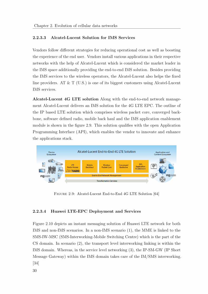
Alcatel-Lucent 4G LTE solution Along with the end-to-end network manage-
ment Alcatel-Lucent delivers an IMS solution for the 4G LTE EPC. The outline of
the IP based LTE solution which comprises wireless packet core, converged back-
bone, software defined radio, mobile back haul and the IMS application enablement
module is shown in the figure 2.9. This solution qualifies with the open Application
Programming Interface (API), which enables the vendor to innovate and enhance
the applications stack.
Figure 2.9: Alcatel-Lucent End-to-End 4G LTE Solution [64]
2.2.3.4 Huawei LTE-EPC Deployment and Services
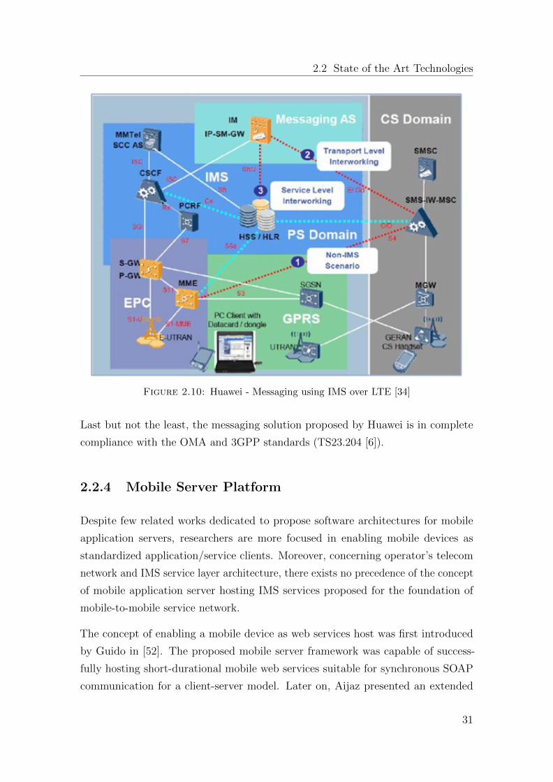
Figure 2.10 depicts an instant messaging solution of Huawei LTE network for both
IMS and non-IMS scenarios. In a non-IMS scenario (1), the MME is linked to the
SMS-IW-MSC (SMS-Interworking-Mobile Switching Centre) which is the part of the
CS domain. In scenario (2), the transport level interworking linking is within the
IMS domain. Whereas, in the service level networking (3), the IP-SM-GW (IP Short
Message Gateway) within the IMS domain takes care of the IM/SMS interworking.
[34]
30
2.2 State of the Art Technologies
Figure 2.10: Huawei - Messaging using IMS over LTE [34]
Last but not the least, the messaging solution proposed by Huawei is in complete
compliance with the OMA and 3GPP standards (TS23.204 [6]).
2.2.4 Mobile Server Platform
Despite few related works dedicated to propose software architectures for mobile
application servers, researchers are more focused in enabling mobile devices as
standardized application/service clients. Moreover, concerning operator’s telecom
network and IMS service layer architecture, there exists no precedence of the concept
of mobile application server hosting IMS services proposed for the foundation of
mobile-to-mobile service network.
The concept of enabling a mobile device as web services host was first introduced
by Guido in [52]. The proposed mobile server framework was capable of success-
fully hosting short-durational mobile web services suitable for synchronous SOAP
communication for a client-server model. Later on, Aijaz presented an extended
31
Chapter 2. Evolution of cellular data networks
asynchronous architecture for mobile server framework [9] to support long-durational
mobile web services. In their further study, the same research group proposed a
new RESTful architecture for their mobile server framework and termed it as light
weight compared to the usual SOAP mobile web server [10] [12] [11]. Meanwhile,
Srirama also presented the architectural requirements of a SOAP based mobile web
server [69]. In his research findings, he claimed that the total processing time of a
simple mobile web service on a Mobile Host takes only a small fraction (<10%) of
the total request-response time. Whereas, the rest of the response time is because of
the transmission delay. For accessing multimedia services from mobile terminals, a
research work from academia [30] presents how the Lightweight Application Server
(LAS) can be used to access MPEG-7 based multimedia services from a mobile device.
Based on these LAS mobile services, the authors demonstrate the scenarios how
user communities might use handheld devices to share MPEG-7 based multimedia
services among themselves in order to reduce communication costs or to set up
an ad-hoc community network. They propose the enterprise service bus (ESB)
technology as an alternative middleware approach to provide multimedia services to
mobile devices.
From accessibility point of view of mobile services, Nokia in its research of Mobile
Web Server [81] pointed out the addressability issue of mobile devices over operator
networks. According to their findings, providing direct IP access to mobile devices is
a bottleneck in provisioning M2M service networks. The operators typically employ
firewalls to prevent http access to subscribers devices over the Internet. This fact
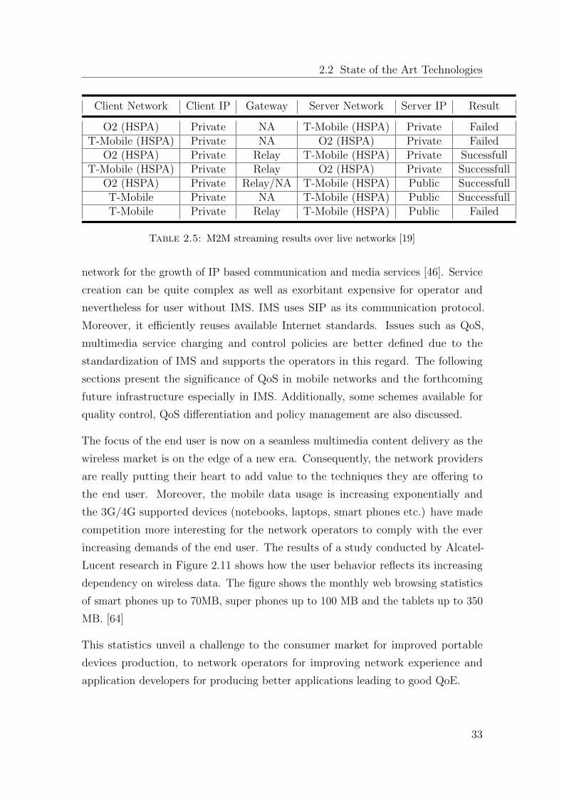
can be observed from [19] explaining how M2M multimedia streaming went through
over two big operator networks, O2 and T-Mobile. Table 2.5 depicts the summary of
live network transactions. It is observed that in case both client and server devices
are connected on private IP addresses, M2M streaming is not possible unless an
intermediate access gateway is involved. Furthermore, the direct streaming went
successful in case the server is on public IP address with the exception that operator
restricts the session explicitly.
2.2.5 Quality of Service in Mobile Networks
3GPP Release 5 was the first one to introduce the IP Multimedia Subsystem (IMS).
The service providers use the IMS as a standard architecture for a cost-effective
32
2.2 State of the Art Technologies
Client Network Client IP Gateway Server Network Server IP Result
O2 (HSPA) Private NA T-Mobile (HSPA) Private FailedT-Mobile (HSPA) Private NA O2 (HSPA) Private Failed
O2 (HSPA) Private Relay T-Mobile (HSPA) Private SucessfullT-Mobile (HSPA) Private Relay O2 (HSPA) Private Successfull
O2 (HSPA) Private Relay/NA T-Mobile (HSPA) Public SuccessfullT-Mobile Private NA T-Mobile (HSPA) Public SuccessfullT-Mobile Private Relay T-Mobile (HSPA) Public Failed
Table 2.5: M2M streaming results over live networks [19]
network for the growth of IP based communication and media services [46]. Service
creation can be quite complex as well as exorbitant expensive for operator and
nevertheless for user without IMS. IMS uses SIP as its communication protocol.
Moreover, it efficiently reuses available Internet standards. Issues such as QoS,
multimedia service charging and control policies are better defined due to the
standardization of IMS and supports the operators in this regard. The following
sections present the significance of QoS in mobile networks and the forthcoming
future infrastructure especially in IMS. Additionally, some schemes available for
quality control, QoS differentiation and policy management are also discussed.
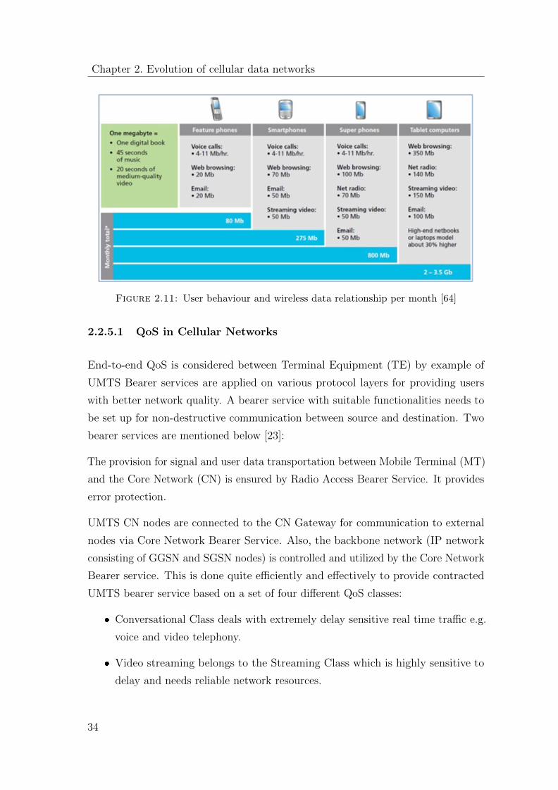
The focus of the end user is now on a seamless multimedia content delivery as the
wireless market is on the edge of a new era. Consequently, the network providers
are really putting their heart to add value to the techniques they are offering to
the end user. Moreover, the mobile data usage is increasing exponentially and
the 3G/4G supported devices (notebooks, laptops, smart phones etc.) have made
competition more interesting for the network operators to comply with the ever
increasing demands of the end user. The results of a study conducted by Alcatel-
Lucent research in Figure 2.11 shows how the user behavior reflects its increasing
dependency on wireless data. The figure shows the monthly web browsing statistics
of smart phones up to 70MB, super phones up to 100 MB and the tablets up to 350
MB. [64]
This statistics unveil a challenge to the consumer market for improved portable
devices production, to network operators for improving network experience and
application developers for producing better applications leading to good QoE.
33
Chapter 2. Evolution of cellular data networks
Figure 2.11: User behaviour and wireless data relationship per month [64]
2.2.5.1 QoS in Cellular Networks
End-to-end QoS is considered between Terminal Equipment (TE) by example of
UMTS Bearer services are applied on various protocol layers for providing users
with better network quality. A bearer service with suitable functionalities needs to
be set up for non-destructive communication between source and destination. Two
bearer services are mentioned below [23]:
The provision for signal and user data transportation between Mobile Terminal (MT)
and the Core Network (CN) is ensured by Radio Access Bearer Service. It provides
error protection.
UMTS CN nodes are connected to the CN Gateway for communication to external
nodes via Core Network Bearer Service. Also, the backbone network (IP network
consisting of GGSN and SGSN nodes) is controlled and utilized by the Core Network
Bearer service. This is done quite efficiently and effectively to provide contracted
UMTS bearer service based on a set of four different QoS classes:
� Conversational Class deals with extremely delay sensitive real time traffic e.g.
voice and video telephony.
� Video streaming belongs to the Streaming Class which is highly sensitive to
delay and needs reliable network resources.
34
2.2 State of the Art Technologies
� Web Surfing, Email etc. lie in the Interactive Class which is pretty less sensitive
as compared to conversational and streaming classes.
� Background Class is known as the most delay insensitive class and is mostly
used by the applications running in the background.
QoS in fact is an important issue in 3GPP standardization, see [39].
2.2.5.2 QoS technical Key Performance Indicators (KPI)
Following KPIs are helpful for the Technical QoS measurements by service providers.
[37]
� Delay Network delay is a major factor in user satisfaction. Once a network
session is established, the delay is the time taken by the network to successfully
deliver the content from source to destination. In case the network is burdened,
data packets in long queues of IP networks experience considerable delay.
� Jitter The variations in network delay is referred to as Jitter. It has a great
influence on the end user perception of a delay sensitive service.
� Throughput Bits or Bytes per second are the unit for throughput in a network.
QoS greatly depends on the throughput received by a user device over the
network. Most of the time, it turns out quite hard to prioritize resources for
particular applications like multimedia services. It is because of the ups and
downs in the traffic load over the shared medium. Consequently, the user
experience is relegated in the congestion time.
� Bandwidth Bandwidth of radio channels is shared between the users and is
also considered a key parameter of QoS. It tells about both the available and
busy resources for traffic in a network. The concept can better be understood by
the example of a user who is trying to access a videophone paid service within
a WLAN locale. He would require a reliable bandwidth for uninterrupted
usage; otherwise, he would be truly disappointed and frustrated.
� Packet Loss Packet loss rate is inversely proportional to user satisfaction. It
is an important factor of QoS. Packet loss in IP network occurs mainly during
the routing process between the service provider server and the end user or it
35
Chapter 2. Evolution of cellular data networks
may also occur due to some hardware problem. Both generally result in the
loss of information. The packets are retransmitted in case of packet switch
network, increasing the network delay even more. For example when some
VoIP or video content is requested over the wireless network and it faces packet
loss, the user perception may be considerably reduced.
� Bit Error Rate (BER) Some environmental factors like noise, fading and
interference also have a bad influence on the wireless networks and cause
receiver degradation due to errors in transmitted bits.
2.2.5.3 QoS measurement technique
iQoS - Individual QoS [23] is a calculation technique in cellular networks which
calculates per user satisfaction rate. This per user satisfaction rate is a vital
parameter. The iQoS scheme prioritizes the users on the basis of bad QoS so that
the users facing issues can be pointed out and accommodated for corrective measures
at earliest. This whole process is followed in order to provide the users with improved
services.
Users who are in close vicinity of a base station have better radio signal quality than
those who are more distant. Users who face poor signal quality may suffer from call
dropping and call blocking. Their QoS can be improved by iQoS measurement and
proper reaction by the mobile network.
2.2.5.4 Session based QoS
The IMS assists the network and service providers to deal with user/session based
policies. In this section, we illustrate three variants of QoS support: Connection
Based QoS, Flow Based QoS and Session Based QoS. [34].
� Connection Based QoS The connection based quality mechanism is inept
for the input and output, scalability and the overall performance. This type of
QoS necessitates absolute bandwidth (a circuit switched channel) before any
data transaction is completed. [34]
� Flow Based QoS It supports the relative priority policy of packet switched
data flows and cannot be controlled without the help of the edge devices.
36
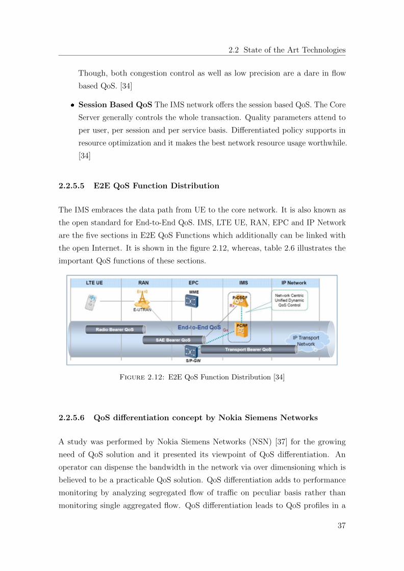
2.2 State of the Art Technologies
Though, both congestion control as well as low precision are a dare in flow
based QoS. [34]
� Session Based QoS The IMS network offers the session based QoS. The Core
Server generally controls the whole transaction. Quality parameters attend to
per user, per session and per service basis. Differentiated policy supports in
resource optimization and it makes the best network resource usage worthwhile.
[34]
2.2.5.5 E2E QoS Function Distribution
The IMS embraces the data path from UE to the core network. It is also known as
the open standard for End-to-End QoS. IMS, LTE UE, RAN, EPC and IP Network
are the five sections in E2E QoS Functions which additionally can be linked with
the open Internet. It is shown in the figure 2.12, whereas, table 2.6 illustrates the
important QoS functions of these sections.
Figure 2.12: E2E QoS Function Distribution [34]
2.2.5.6 QoS differentiation concept by Nokia Siemens Networks
A study was performed by Nokia Siemens Networks (NSN) [37] for the growing
need of QoS solution and it presented its viewpoint of QoS differentiation. An
operator can dispense the bandwidth in the network via over dimensioning which is
believed to be a practicable QoS solution. QoS differentiation adds to performance
monitoring by analyzing segregated flow of traffic on peculiar basis rather than
monitoring single aggregated flow. QoS differentiation leads to QoS profiles in a
37
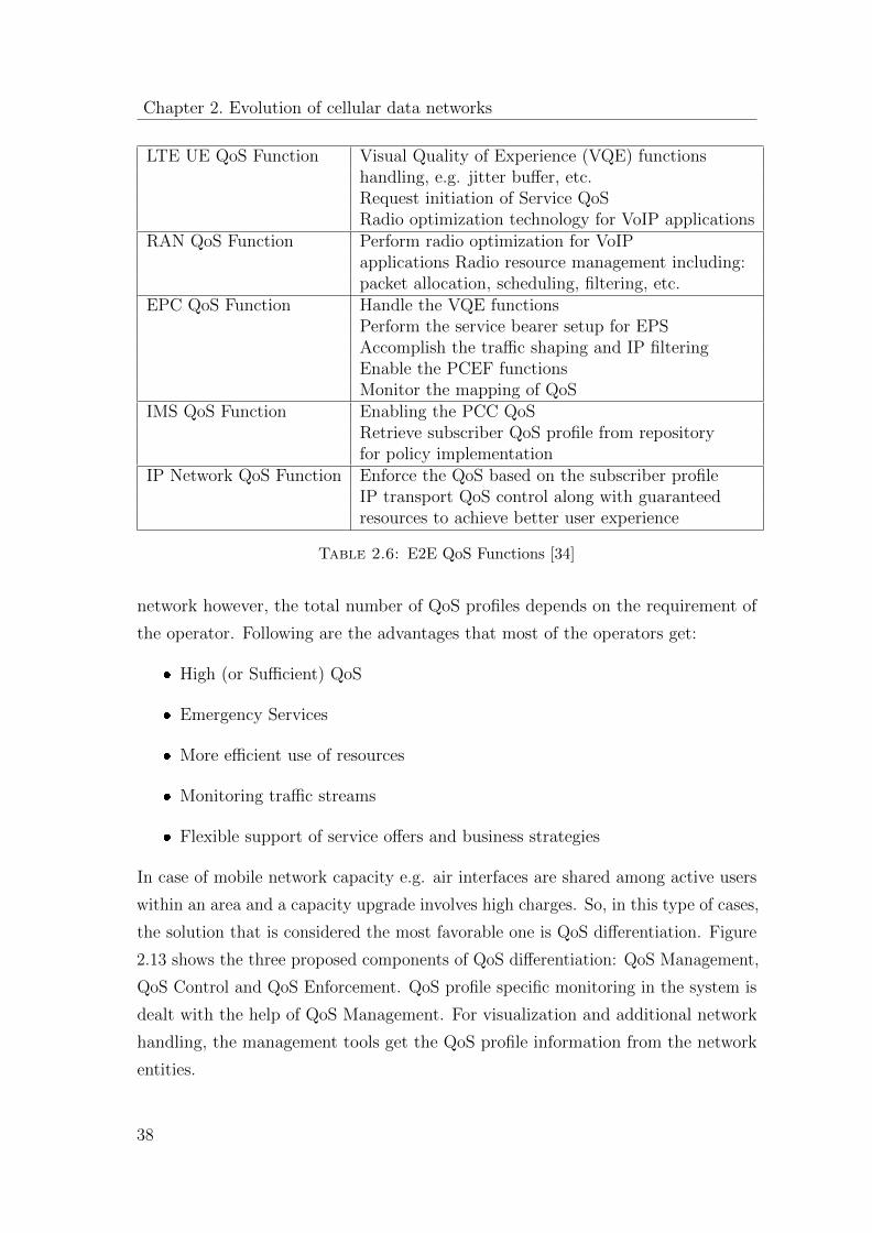
Chapter 2. Evolution of cellular data networks
LTE UE QoS Function Visual Quality of Experience (VQE) functionshandling, e.g. jitter buffer, etc.Request initiation of Service QoSRadio optimization technology for VoIP applications
RAN QoS Function Perform radio optimization for VoIPapplications Radio resource management including:packet allocation, scheduling, filtering, etc.
EPC QoS Function Handle the VQE functionsPerform the service bearer setup for EPSAccomplish the traffic shaping and IP filteringEnable the PCEF functionsMonitor the mapping of QoS
IMS QoS Function Enabling the PCC QoSRetrieve subscriber QoS profile from repositoryfor policy implementation
IP Network QoS Function Enforce the QoS based on the subscriber profileIP transport QoS control along with guaranteedresources to achieve better user experience
Table 2.6: E2E QoS Functions [34]
network however, the total number of QoS profiles depends on the requirement of
the operator. Following are the advantages that most of the operators get:
� High (or Sufficient) QoS
� Emergency Services
� More efficient use of resources
� Monitoring traffic streams
� Flexible support of service offers and business strategies
In case of mobile network capacity e.g. air interfaces are shared among active users
within an area and a capacity upgrade involves high charges. So, in this type of cases,
the solution that is considered the most favorable one is QoS differentiation. Figure
2.13 shows the three proposed components of QoS differentiation: QoS Management,
QoS Control and QoS Enforcement. QoS profile specific monitoring in the system is
dealt with the help of QoS Management. For visualization and additional network
handling, the management tools get the QoS profile information from the network
entities.
38
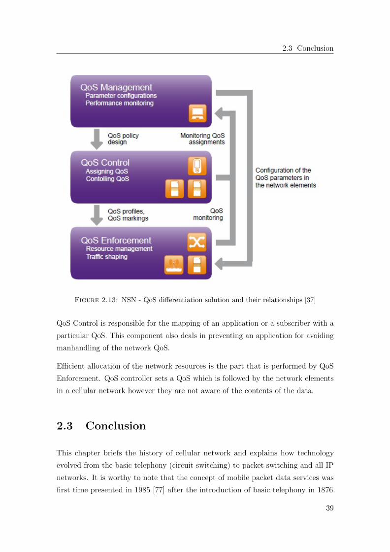
2.3 Conclusion
Figure 2.13: NSN - QoS differentiation solution and their relationships [37]
QoS Control is responsible for the mapping of an application or a subscriber with a
particular QoS. This component also deals in preventing an application for avoiding
manhandling of the network QoS.
Efficient allocation of the network resources is the part that is performed by QoS
Enforcement. QoS controller sets a QoS which is followed by the network elements
in a cellular network however they are not aware of the contents of the data.
2.3 Conclusion
This chapter briefs the history of cellular network and explains how technology
evolved from the basic telephony (circuit switching) to packet switching and all-IP
networks. It is worthy to note that the concept of mobile packet data services was
first time presented in 1985 [77] after the introduction of basic telephony in 1876.
39
Chapter 2. Evolution of cellular data networks
This means the advanced data networks (all-IP networks) took only about 30 years
to reach at this stage.
The state of the art section presents example of advances made by the industry
(Ericsson, Huawei, Alcatel Lucent) and research (e.g. Fraunhofer Fokus) in the IMS
and LTE mobile networks domain. It has been identified that there exists no much
work explicitly presenting the concept and architecture of mobile application server
in the operator LTE/IMS network. The quality of service concept, parameters and
issues in mobile networks are extensively studied and some strategies are identified
to tackle these issues. Based on this conclusive study, the dissertation work has
utilized the following state of the art tools and concepts in the realization of M2M
service network :
� The base architecture of Mobile Server Platform [9] has been extended for
standardized cellular interfaces and protocols of LTE-EPC system.
� Ericsson testbed for IMS ecosystem [60]
� Ericsson test agents for SIP and VoIP services [60]
� Fraunhofer testbed for EPC ecosystem [49]
� Session based QoS as a QoS measurement technique [34]
� QoS differentiation solution similar to proposed by Nokia Siemens Networks
[37]
� Policy and charging framework devised by 3GPP [38]
40
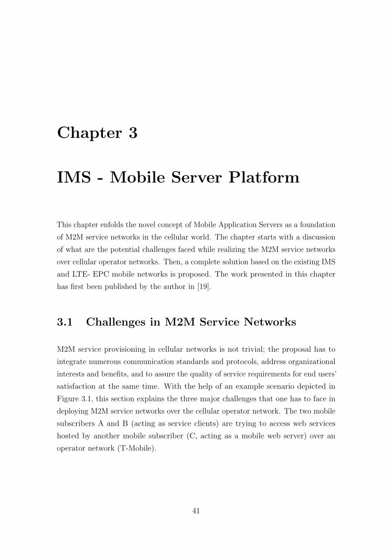
Chapter 3
IMS - Mobile Server Platform
This chapter enfolds the novel concept of Mobile Application Servers as a foundation
of M2M service networks in the cellular world. The chapter starts with a discussion
of what are the potential challenges faced while realizing the M2M service networks
over cellular operator networks. Then, a complete solution based on the existing IMS
and LTE- EPC mobile networks is proposed. The work presented in this chapter
has first been published by the author in [19].
3.1 Challenges in M2M Service Networks
M2M service provisioning in cellular networks is not trivial; the proposal has to
integrate numerous communication standards and protocols, address organizational
interests and benefits, and to assure the quality of service requirements for end users’
satisfaction at the same time. With the help of an example scenario depicted in
Figure 3.1, this section explains the three major challenges that one has to face in
deploying M2M service networks over the cellular operator network. The two mobile
subscribers A and B (acting as service clients) are trying to access web services
hosted by another mobile subscriber (C, acting as a mobile web server) over an
operator network (T-Mobile).
41
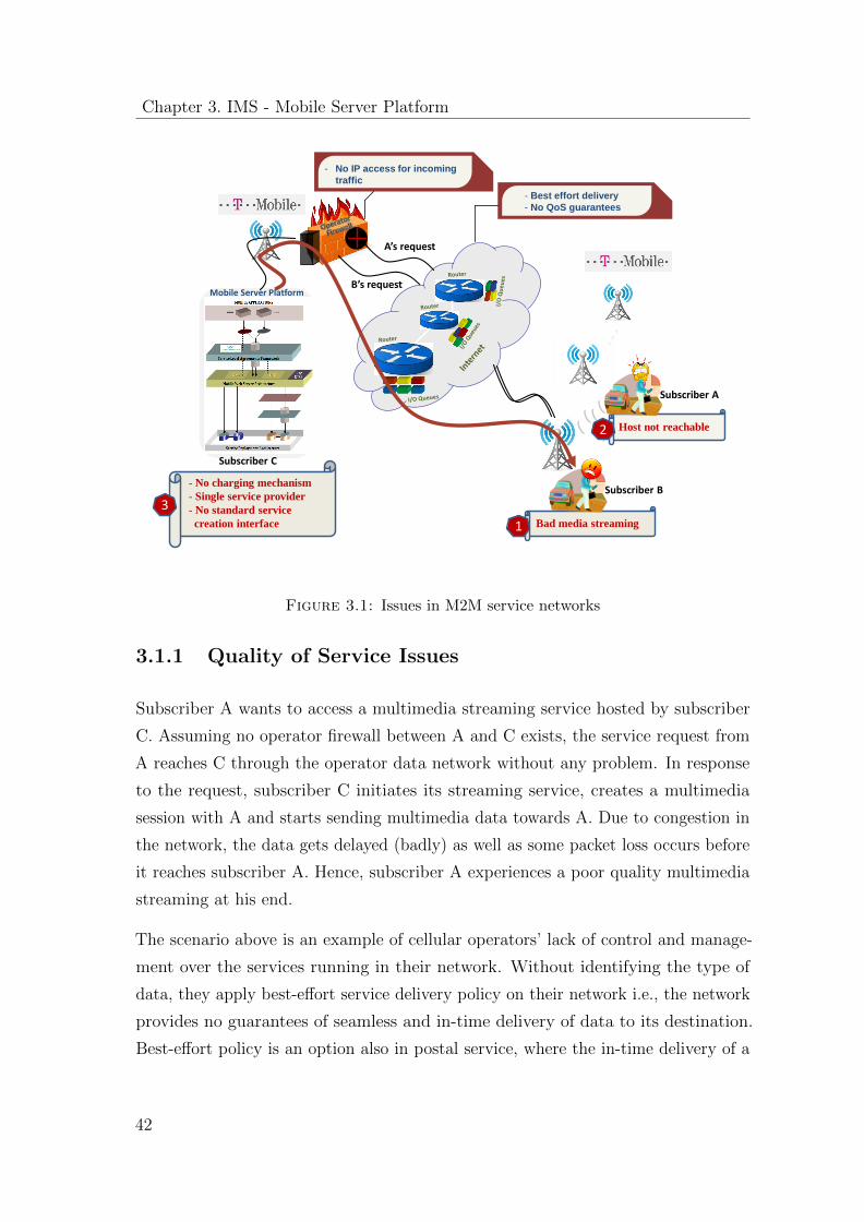
Chapter 3. IMS - Mobile Server Platform
Subscriber A
Host not reachable
- Best effort delivery
- No QoS guarantees
- No IP access for incoming
traffic
Bad media streaming
Mobile Server Platform
Subscriber B
A’s request
B’s request
- No charging mechanism
- Single service provider
- No standard service
creation interface
3
1
2
Subscriber C
Figure 3.1: Issues in M2M service networks
3.1.1 Quality of Service Issues
Subscriber A wants to access a multimedia streaming service hosted by subscriber
C. Assuming no operator firewall between A and C exists, the service request from
A reaches C through the operator data network without any problem. In response
to the request, subscriber C initiates its streaming service, creates a multimedia
session with A and starts sending multimedia data towards A. Due to congestion in
the network, the data gets delayed (badly) as well as some packet loss occurs before
it reaches subscriber A. Hence, subscriber A experiences a poor quality multimedia
streaming at his end.
The scenario above is an example of cellular operators’ lack of control and manage-
ment over the services running in their network. Without identifying the type of
data, they apply best-effort service delivery policy on their network i.e., the network
provides no guarantees of seamless and in-time delivery of data to its destination.
Best-effort policy is an option also in postal service, where the in-time delivery of a
42
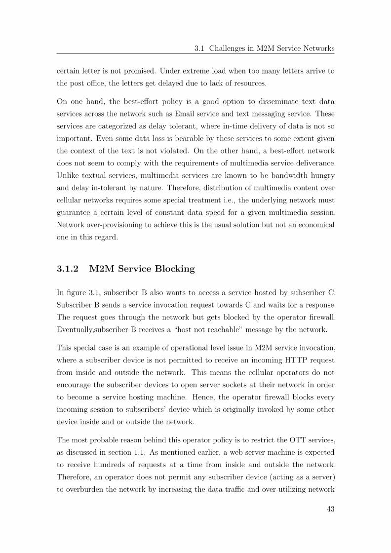
3.1 Challenges in M2M Service Networks
certain letter is not promised. Under extreme load when too many letters arrive to
the post office, the letters get delayed due to lack of resources.
On one hand, the best-effort policy is a good option to disseminate text data
services across the network such as Email service and text messaging service. These
services are categorized as delay tolerant, where in-time delivery of data is not so
important. Even some data loss is bearable by these services to some extent given
the context of the text is not violated. On the other hand, a best-effort network
does not seem to comply with the requirements of multimedia service deliverance.
Unlike textual services, multimedia services are known to be bandwidth hungry
and delay in-tolerant by nature. Therefore, distribution of multimedia content over
cellular networks requires some special treatment i.e., the underlying network must
guarantee a certain level of constant data speed for a given multimedia session.
Network over-provisioning to achieve this is the usual solution but not an economical
one in this regard.
3.1.2 M2M Service Blocking
In figure 3.1, subscriber B also wants to access a service hosted by subscriber C.
Subscriber B sends a service invocation request towards C and waits for a response.
The request goes through the network but gets blocked by the operator firewall.
Eventually,subscriber B receives a “host not reachable” message by the network.
This special case is an example of operational level issue in M2M service invocation,
where a subscriber device is not permitted to receive an incoming HTTP request
from inside and outside the network. This means the cellular operators do not
encourage the subscriber devices to open server sockets at their network in order
to become a service hosting machine. Hence, the operator firewall blocks every
incoming session to subscribers’ device which is originally invoked by some other
device inside and or outside the network.
The most probable reason behind this operator policy is to restrict the OTT services,
as discussed in section 1.1. As mentioned earlier, a web server machine is expected
to receive hundreds of requests at a time from inside and outside the network.
Therefore, an operator does not permit any subscriber device (acting as a server)
to overburden the network by increasing the data traffic and over-utilizing network
43
Chapter 3. IMS - Mobile Server Platform
resources in order to serve the incoming service requests. Hence, considering the
cheap flat-rate data tariffs of cellular operators, how can an operator tolerate an
individual subscriber to become an OTT-type server and over-utilize resources.
There are some state-of-the-art techniques useful to bypass NATs (Network Address
Translation) and network firewalls. Such techniques are e.g. applied by OTT service
providers to bypass operator firewall restrictions in cellular networks. However, as
discussed in section 1.1, operators see this OTT model as a threat to their business
ecosystem unless they get some real benefit out of it.
3.1.3 M2M Service Platform
The M2M conceptual model is somewhat different from a typical client-server model,
where a server machine in the network is dedicated for serving clients connected to
the network. In an M2M service provisioning model each node connected to the
network is aimed to have the ability to become a service host (server) or a service
client at the same time. Hence, they require a Mobile Server Platform (MSP) that
has the ability to act both as a server and a client simultaneously.
This case study sees it as a big challenge to realize an MSP that conforms to the
standards of the cellular industry. Therefore, it identifies some main limitations of
the MSP introduced in [9] to be used as a standardized service delivery platform in
the foundation of M2M service networks for cellular systems:
� The MSP platform does not specify a standardized way to register itself as a
client or an application server with the cellular data network.
� It does not define the service discovery and service invocation mechanisms by
using the standardized interfaces and protocols of the cellular system.
� It does not integrate with the standardized policy and charging solution of an
operator data network.
44
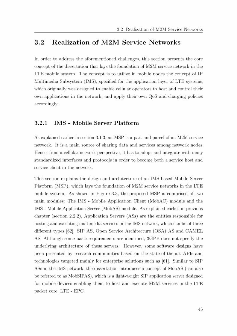
3.2 Realization of M2M Service Networks
3.2 Realization of M2M Service Networks
In order to address the aforementioned challenges, this section presents the core
concept of the dissertation that lays the foundation of M2M service network in the
LTE mobile system. The concept is to utilize in mobile nodes the concept of IP
Multimedia Subsystem (IMS), specified for the application layer of LTE systems,
which originally was designed to enable cellular operators to host and control their
own applications in the network, and apply their own QoS and charging policies
accordingly.
3.2.1 IMS - Mobile Server Platform
As explained earlier in section 3.1.3, an MSP is a part and parcel of an M2M service
network. It is a main source of sharing data and services among network nodes.
Hence, from a cellular network perspective, it has to adopt and integrate with many
standardized interfaces and protocols in order to become both a service host and
service client in the network.
This section explains the design and architecture of an IMS based Mobile Server
Platform (MSP), which lays the foundation of M2M service networks in the LTE
mobile system. As shown in Figure 3.3, the proposed MSP is comprised of two
main modules: The IMS - Mobile Application Client (MobAC) module and the
IMS - Mobile Application Server (MobAS) module. As explained earlier in previous
chapter (section 2.2.2), Application Servers (ASs) are the entities responsible for
hosting and executing multimedia services in the IMS network, which can be of three
different types [62]: SIP AS, Open Service Architecture (OSA) AS and CAMEL
AS. Although some basic requirements are identified, 3GPP does not specify the
underlying architecture of these servers. However, some software designs have
been presented by research communities based on the state-of-the-art APIs and
technologies targeted mainly for enterprise solutions such as [61]. Similar to SIP
ASs in the IMS network, the dissertation introduces a concept of MobAS (can also
be referred to as MobSIPAS), which is a light-weight SIP application server designed
for mobile devices enabling them to host and execute M2M services in the LTE
packet core, LTE - EPC.
45
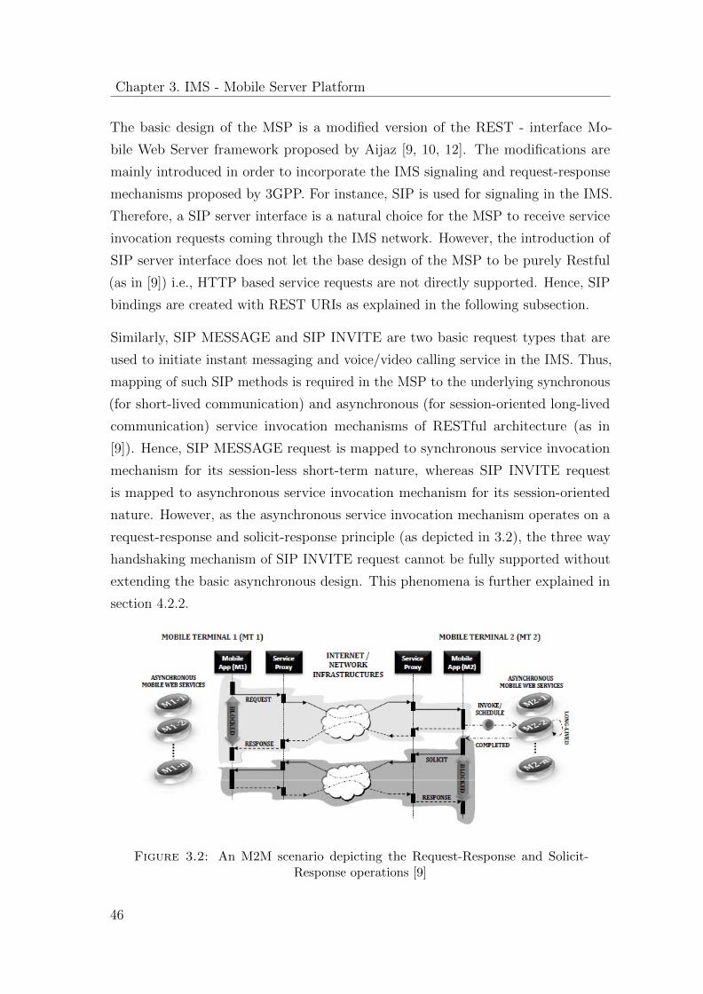
Chapter 3. IMS - Mobile Server Platform
The basic design of the MSP is a modified version of the REST - interface Mo-
bile Web Server framework proposed by Aijaz [9, 10, 12]. The modifications are
mainly introduced in order to incorporate the IMS signaling and request-response
mechanisms proposed by 3GPP. For instance, SIP is used for signaling in the IMS.
Therefore, a SIP server interface is a natural choice for the MSP to receive service
invocation requests coming through the IMS network. However, the introduction of
SIP server interface does not let the base design of the MSP to be purely Restful
(as in [9]) i.e., HTTP based service requests are not directly supported. Hence, SIP
bindings are created with REST URIs as explained in the following subsection.
Similarly, SIP MESSAGE and SIP INVITE are two basic request types that are
used to initiate instant messaging and voice/video calling service in the IMS. Thus,
mapping of such SIP methods is required in the MSP to the underlying synchronous
(for short-lived communication) and asynchronous (for session-oriented long-lived
communication) service invocation mechanisms of RESTful architecture (as in
[9]). Hence, SIP MESSAGE request is mapped to synchronous service invocation
mechanism for its session-less short-term nature, whereas SIP INVITE request
is mapped to asynchronous service invocation mechanism for its session-oriented
nature. However, as the asynchronous service invocation mechanism operates on a
request-response and solicit-response principle (as depicted in 3.2), the three way
handshaking mechanism of SIP INVITE request cannot be fully supported without
extending the basic asynchronous design. This phenomena is further explained in
section 4.2.2.
Figure 3.2: An M2M scenario depicting the Request-Response and Solicit-Response operations [9]
46
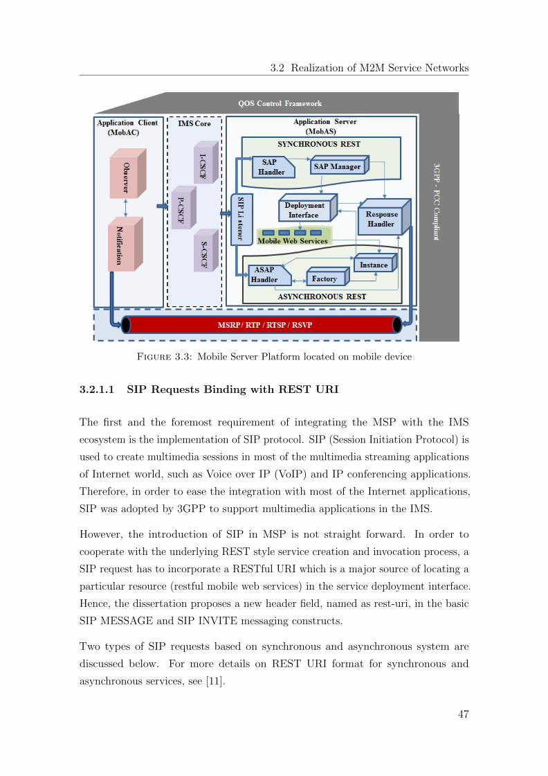
3.2 Realization of M2M Service Networks
Figure 3.3: Mobile Server Platform located on mobile device
3.2.1.1 SIP Requests Binding with REST URI
The first and the foremost requirement of integrating the MSP with the IMS
ecosystem is the implementation of SIP protocol. SIP (Session Initiation Protocol) is
used to create multimedia sessions in most of the multimedia streaming applications
of Internet world, such as Voice over IP (VoIP) and IP conferencing applications.
Therefore, in order to ease the integration with most of the Internet applications,
SIP was adopted by 3GPP to support multimedia applications in the IMS.
However, the introduction of SIP in MSP is not straight forward. In order to
cooperate with the underlying REST style service creation and invocation process, a
SIP request has to incorporate a RESTful URI which is a major source of locating a
particular resource (restful mobile web services) in the service deployment interface.
Hence, the dissertation proposes a new header field, named as rest-uri, in the basic
SIP MESSAGE and SIP INVITE messaging constructs.
Two types of SIP requests based on synchronous and asynchronous system are
discussed below. For more details on REST URI format for synchronous and
asynchronous services, see [11].
47
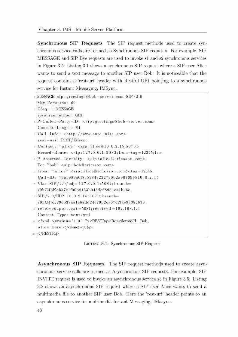
Chapter 3. IMS - Mobile Server Platform
Synchronous SIP Requests The SIP request methods used to create syn-
chronous service calls are termed as Synchronous SIP requests. For example, SIP
MESSAGE and SIP Bye requests are used to invoke s1 and s2 synchronous services
in Figure 3.5. Listing 3.1 shows a synchronous SIP request where a SIP user Alice
wants to send a text message to another SIP user Bob. It is noticeable that the
request contains a ’rest-uri’ header with Restful URI pointing to a synchronous
service for Instant Messaging, IMSync.
1 MESSAGE s i p : greetings@bob−s e r v e r . com SIP /2 .0
Max−Forwards : 69
3 CSeq : 1 MESSAGE
resourcemethod : GET
5 P−Called−Party−ID : <s i p : greetings@bob−s e r v e r . com>
Content−Length : 84
7 Call−In f o : <http ://www. antd . n i s t . gov>
r e s t−u r i : POST/IMsync
9 Contact : ” a l i c e ” <s i p : a l i ce@10 .0 .2 .15 :5070 >
Record−Route : <s i p : 1 2 7 . 0 . 0 . 1 : 5 0 8 2 ; from−tag =12345; l r>
11 P−Asserted−I d e n t i t y : <s i p : a l i c e @ e r i c s s o n . com>
To : ”bob” <s i p : bob@ericsson . com>
13 From : ” a l i c e ” <s i p : a l i c e @ e r i c s s o n . com>; tag =12345
Call−ID : 79 a6e89a0f8c55849222730b2a90769f@10 . 0 . 2 . 1 5
15 Via : SIP /2 .0/ udp 1 2 7 . 0 . 0 . 1 : 5 0 8 2 ; branch=
z9hG4bKaba7c1f00b8133b045de689d1ca1b46e ,
17 SIP /2 .0/UDP 1 0 . 0 . 2 . 1 5 : 5 0 7 0 ; branch=
z9hG4bK29cb37aa1e68dd24e29b2ca0762fae9a383639 ;
19 r e c e i v e d p o r t e x t =5081; r e c e i v e d =192 .168 .1 .4
Content−Type : text/xml
21 <?xml version=’ 1 .0 ’ ?><RESTRq><Rq><demo>Hi Bob ,
a l i c e here !</demo></Rq>
23 </RESTRq>
Listing 3.1: Synchronous SIP Request
Asynchronous SIP Requests The SIP request methods used to create asyn-
chronous service calls are termed as Asynchronous SIP requests. For example, SIP
INVITE request is used to invoke an asynchronous service s3 in Figure 3.5. Listing
3.2 shows an asynchronous SIP request where a SIP user Alice wants to send a
multimedia file to another SIP user Bob. Here the ’rest-uri’ header points to an
asynchronous service for multimedia Instant Messaging, IMasync.
48
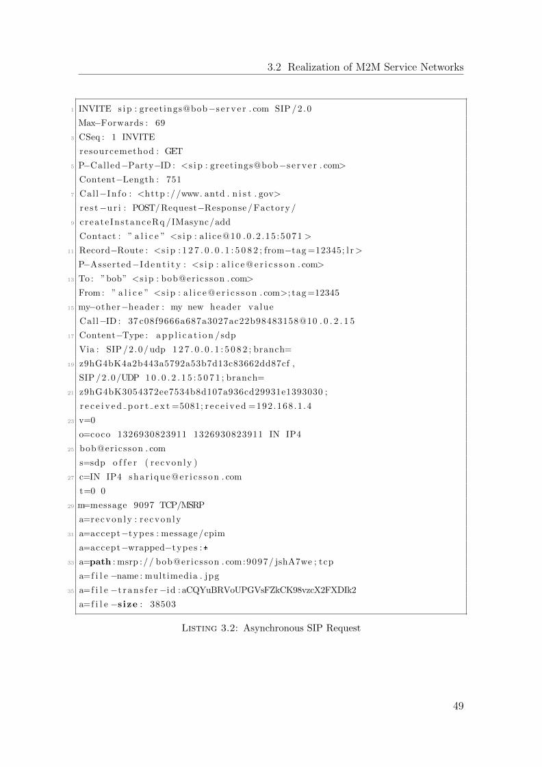
3.2 Realization of M2M Service Networks
1 INVITE s i p : greetings@bob−s e r v e r . com SIP /2 .0
Max−Forwards : 69
3 CSeq : 1 INVITE
resourcemethod : GET
5 P−Called−Party−ID : <s i p : greetings@bob−s e r v e r . com>
Content−Length : 751
7 Call−In f o : <http ://www. antd . n i s t . gov>
r e s t−u r i : POST/Request−Response/ Factory /
9 create InstanceRq /IMasync/add
Contact : ” a l i c e ” <s i p : a l i ce@10 .0 .2 .15 :5071 >
11 Record−Route : <s i p : 1 2 7 . 0 . 0 . 1 : 5 0 8 2 ; from−tag =12345; l r>
P−Asserted−I d e n t i t y : <s i p : a l i c e @ e r i c s s o n . com>
13 To : ”bob” <s i p : bob@ericsson . com>
From : ” a l i c e ” <s i p : a l i c e @ e r i c s s o n . com>; tag =12345
15 my−other−header : my new header va lue
Cal l−ID : 37 c08f9666a687a3027ac22b98483158@10 . 0 . 2 . 1 5
17 Content−Type : a p p l i c a t i o n /sdp
Via : SIP /2 .0/ udp 1 2 7 . 0 . 0 . 1 : 5 0 8 2 ; branch=
19 z9hG4bK4a2b443a5792a53b7d13c83662dd87cf ,
SIP /2 .0/UDP 1 0 . 0 . 2 . 1 5 : 5 0 7 1 ; branch=
21 z9hG4bK3054372ee7534b8d107a936cd29931e1393030 ;
r e c e i v e d p o r t e x t =5081; r e c e i v e d =192 .168 .1 .4
23 v=0
o=coco 1326930823911 1326930823911 IN IP4
25 bob@ericsson . com
s=sdp o f f e r ( r ecvon ly )
27 c=IN IP4 shar ique@er i c s son . com
t=0 0
29 m=message 9097 TCP/MSRP
a=recvon ly : r ecvon ly
31 a=accept−types : message/cpim
a=accept−wrapped−types :*
33 a=path : msrp :// bob@ericsson . com:9097/ jshA7we ; tcp
a=f i l e −name : multimedia . jpg
35 a=f i l e −t r a n s f e r−id : aCQYuBRVoUPGVsFZkCK98vzcX2FXDIk2
a=f i l e −s ize : 38503
Listing 3.2: Asynchronous SIP Request
49
Chapter 3. IMS - Mobile Server Platform
3.2.1.2 Mobile Application Client
As shown in Figure 3.3, Observer is an integral component of MobAC which is
responsible to create and send synchronous and asynchronous service calls. The
synchronous service calls are exposed based on the request-response interaction
policy of WSDL operations [80]. In a request-response process each client request
is followed by a response. Therefore, the Observer keeps itself in a blocked state
after a synchronous service call until the response is back from the requested service
invoked by the MobAS. On the contrary, the mechanism of asynchronous service
calls is derived by incorporating the request-response and solicit-response WSDL
operations [80]. Similar to request-response operation, solicit-response is a process
where every request is followed by a response, but the roles of service provider and
service consumer are reversed.
In contrast to synchronous calls, the Observer does not wait for a complete service
response after an asynchronous service call, rather an acknowledgment is sent by
the MobAS to the Observer that the request is received. However, during this
request-response operation the Observer provides an End Point Reference (EPR)
to the MobAS where the service outcome shall be notified. After this operation,
the service starts running independently in a separate thread sending response back
to the provided EPR in the form of short notifications with partial results time
to time or a single complete response at the end of successful task completion.
This process of result notification in asynchronous service calls is analogous to the
solicit-response operation. Typically, an asynchronous interaction is utilized to
realize the session based services such as multimedia messaging and streaming, where
the initial request-response operation is used to create session with an additional
acknowledgment message and the solicit-response approach is used for actual media
delivery by the service.
3.2.1.3 Mobile Application Server
In Figure 3.3, the MobAS module starts working when it receives a SIP request
from a MobAC via the IMS network, which is the SIP signaling network in between
MobACs and MobASs that are connected by the IP-based operator network that
50
3.2 Realization of M2M Service Networks
provides PCRF. The SIP Listener separates the Restful-URI string from the SIP-
based service request and parses it to extract the target service information such
as service name, request method and resource method. The parsed information is
then utilized by SIP Listener to form a Request Object and identify the service type
such as synchronous or asynchronous. It is worth mentioning here that although the
service type can alse be identified by simply knowing the SIP method name, such as,
SIP MESSAGE corresponds to synchronous request and SIP INVITE corresponds
to asynchronous, this approach is avoided in order to keep compliance with the basic
REST architecture introduced in [11].
3.2.1.4 Synchronous Service Invocation
In case the synchronous service request identified by SIP Listener, the Request
Object is passed to the Deployment Interface through SAP (Synchronous Application
Processing) Manager which is responsible for look up and invocation of the target
service. The Deployment Interface maintains a list of all available services along
with their corresponding objects as a key-value mapping. Therefore, it looks up
the corresponding service object in its service inventory and use it to invoke target
service.
3.2.1.5 Asynchronous Service Invocation
An asynchronous service is initiated and executed as a thread, which is the primary
difference between the synchronous and asynchronous services. The asynchronous
service is made a thread because that enables it to be controlled and monitored
and to be in variable states during the course of execution. In case of asynchronous
service request, before parsing and making Request Object the SIP Listener first
checks whether the request message contains an SDP (Session Description Protocol)
offer, extracts the media information and verifies the availability of the target
service. An SDP offer is used in the SIP INVITE request in order to negotiate
over streaming media parameters between two parties before the actual media
transmission starts. The SDP works in conjunction with RTP and MSRP protocols
for real-time streaming and multimedia instant messaging services. The SDP headers
and messaging constructs are defined in the IETF specification [54].
51
Chapter 3. IMS - Mobile Server Platform
Considering the SDP offer is valid and accepted by the SIP Listener, the Request
Object is passed to ASAP (Asynchronous Application Processing) Handler which
invokes Service Factory to create a new Service Instance for the target service. At
this stage, a 200 OK message is sent to the AC that releases the AC from the blocked
state. With this message the AS also provides two important IDs to the AS: a
request Call-ID for reference to the upcoming final acknowledgment from the AC
and the EPR for newly created service instance for future communication with the
service.
Thus, after sending 200 OK message the control is given to the Deployment Interface
finally along with the Request Object and Service Instance parameters for target
service invocation. In contrast to synchronous service invocation, after inventory
look up the Deployment Interface forms a service thread, save it in database against
the Call-ID and wait for the acknowledgment of the last 200 Ok message from the
AC. Consequently, when the acknowledgment message arrives at Request Handler,
the Deployment Interface is notified along with the Call-ID which in return starts
the corresponding service thread.
3.2.2 M2M Service Provisioning
This section describes how the IMS architecture helps the subscribers’ devices to
make one-to-one contact over the operators cellular network. The dissertation
proposes that M2M services are to be invoked in a client server fashion where one (
client) of the two communicating parties makes request and the other party (server)
serves the request and invokes the requested service.
For every short or long process to be performed by the mobile server, there exists
a service categorized as synchronous(short-term) or asynchronous(long-term) re-
spectively. Therefore, by defining a proper mechanism how MobASs and MobACs
may register themselves in the operator’s network, this section enfolds how an IMS
compliant MSP can be used to realize an M2M chat application over the cellular
operator network.
52
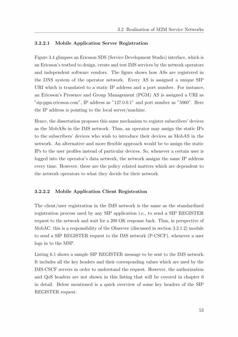
3.2 Realization of M2M Service Networks
3.2.2.1 Mobile Application Server Registration
Figure 3.4 glimpses an Ericsson SDS (Service Development Studio) interface, which is
an Ericsson’s testbed to design, create and test IMS services by the network operators
and independent software vendors. The figure shows how ASs are registered in
the DNS system of the operator network. Every AS is assigned a unique SIP
URI which is translated to a static IP address and a port number. For instance,
an Ericsson’s Presence and Group Management (PGM) AS is assigned a URI as
”sip:pgm.ericsson.com”, IP address as ”127.0.0.1” and port number as ”5060”. Here
the IP address is pointing to the local server/machine.
Hence, the dissertation proposes this same mechanism to register subscribers’ devices
as the MobASs in the IMS network. Thus, an operator may assign the static IPs
to the subscribers’ devices who wish to introduce their devices as MobAS in the
network. An alternative and more flexible approach would be to assign the static
IPs to the user profiles instead of particular devices. So, whenever a certain user is
logged into the operator’s data network, the network assigns the same IP address
every time. However, these are the policy related matters which are dependent to
the network operators to what they decide for their network.
3.2.2.2 Mobile Application Client Registration
The client/user registration in the IMS network is the same as the standardized
registration process used by any SIP application i.e., to send a SIP REGISTER
request to the network and wait for a 200 OK response back. Thus, in perspective of
MobAC, this is a responsibility of the Observer (discussed in section 3.2.1.2) module
to send a SIP REGISTER request to the IMS network (P-CSCF), whenever a user
logs in to the MSP.
Listing 6.1 shows a sample SIP REGISTER message to be sent to the IMS network.
It includes all the key headers and their corresponding values which are used by the
IMS-CSCF servers in order to understand the request. However, the authorization
and QoS headers are not shown in this listing that will be covered in chapter 6
in detail. Below mentioned is a quick overview of some key headers of the SIP
REGISTER request:
53
Chapter 3. IMS - Mobile Server Platform
Figure 3.4: Mobile Application Server Registration to the Ericsson IMS testbed
Request Line indicates the type of SIP requested method and request uri which
is to be sent to the IMS framework. In the given example the register request
indicates : Method= REGISTER, Request-URI=IMS Framework domain (e.g.
sip:open-ims.test)
Via: It contains the local address of user (bob) i.e., domain (e.g. 192.168.2.105:6060)
where it is expecting the responses to come.
Max-Forward: It is used to limit the number of hops that this request may take
before reaching the recipient. It is decreased by one at each hop. The example in
listing 6.1 shows a count of 70.
To: It contains a user name (”bob”) and a SIP URI < [email protected] >
54
3.2 Realization of M2M Service Networks
From: It also contains a user name ”bob” and a SIP URI < [email protected] >.
It also contains a tag (e.g. tag=12345) which is a pseudo-random sequence inserted
by the SIP application. It works as an identifier of the caller in the dialog.
Call-ID: It is a globally unique identifier of the call generated as the combination
of the IP address and a pseudo-random string. The Call-ID is unique for a call;
however, a call may contain several dialogs. Each dialog is uniquely identified by a
combination of From, To and Call-ID.
CSeq: It contains an integer and a method name. When a transaction starts, the
first message is given a random CSeq. After that it is incremented by one with each
new message. The CSeq header is very useful and it is used to detect non-delivery
of a message or any message which is outdated or out-of-order.
Contact: It contains a SIP URI that is a direct route to user. It contains a
username and a fully qualified domain name (FQDN). It may also have an IP
address. Moreover, the via field in the SIP message header is used to send the
response to the request, however, the Contact field is used to send future requests.
That is why the 200 OK response from receiver goes to sender through proxies.
But when receiver generates a BYE request (a new request and not a response to
INVITE), it goes directly to sender bypassing the proxies.
Content-Type: It contains a description of the message body or an SDP message.
Content-Length: indicates an octet (byte) count of the message body.
REGISTER s i p : bob@open−ims . t e s t SIP /2 .0
2 Call−ID : fa60d272af3e8d7ef33af7445c99322b@192 . 1 6 8 . 2 . 1 0 1
CSeq : 1 REGISTER
4 From : ”bob” <s i p : bob@open−ims . t e s t >; tag =12345
To : ”bob” s i p : bob@open−ims . t e s t
6 Via : SIP /2 .0/UDP 1 9 2 . 1 6 8 . 2 . 1 0 1 : 5 0 7 0 ;
branch=z9hG4bKb6f36916c7b7c863e069f72d6326905a323535
8 Max−Forwards : 70
Contact : ”bob” s i p : bob@192 . 1 6 8 . 2 . 1 0 1 : 5 0 7 0
10 My−Header : my header value
My−Other−Header : my new header va lue
12 Call−In f o : http ://www. antd . n i s t . gov
User−Agent : UCT IMS Cl i en t
14 Expires : 600000
Supported : path , gruu
55
Chapter 3. IMS - Mobile Server Platform
16 Content−Length : 0
Listing 3.3: Initial SIP Register Request
Similarly, for deregistering an already registered user from IMS framework, we need
to send again a REGISTER message to the framework. Therefore, we need two
major improvements in the SIP header, one is the increment of the CSeq number
header and the second is the Expires header field value set to 0. The server analyzes
these two header field values and then the CSCF(s) modules will forward the request
to the HSS and the user status becomes deregister and a notification message is
send back to user.
3.2.2.3 M2M Service Invocation
A two way communication is shown in Figure 3.5 where both devices are capable of
becoming service client and server at the same time by using mobile server platform
(MSP). The MSP is comprised of the IMS mobile application client (MobAC) and
the IMS mobile application server (MobAS). Like SIP ASs in the IMS network, the
MobAS is a mobile based SIP application server capable of hosting and executing
multimedia services. Section 3.2.1 describes the design of MSP in detail. The figure
depicts a chat messaging session between two mobile applications, A1 and A2. The
application A1 requests for an image file from A2. The application server AS2
receives a SIP request message from the client AC1, invokes its messaging service
and sends a 200 Ok response back to AC1. The application A2 reads the message
and picks an image file to be sent to A1. Accordingly, the application client AC2 gets
an acceptance from application A1 by sending a SIP request message and receiving
response from the server AS1 in the same fashion as above. Until this step (no.
10), the messaging service discussed is a fine example of synchronous mobile service
which implements a simple short-lived process i.e., receiving the client request and
sending response back immediately without keeping the client in a blocked state for
long.
Having the initial negotiation done, the application client AC1 sends a SIP INVITE
request to the server AS2 in order to invoke actual media sharing. The AS2 sends
a 200 OK response immediately and invokes a multimedia messaging service later
on after having an ACK message from AC1. At this point, a direct connection is
56
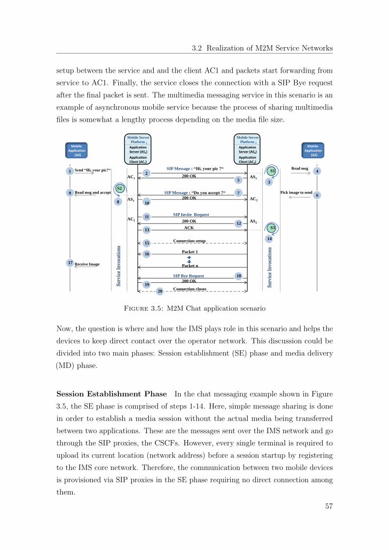
3.2 Realization of M2M Service Networks
setup between the service and and the client AC1 and packets start forwarding from
service to AC1. Finally, the service closes the connection with a SIP Bye request
after the final packet is sent. The multimedia messaging service in this scenario is an
example of asynchronous mobile service because the process of sharing multimedia
files is somewhat a lengthy process depending on the media file size.
S1 Send “Hi, your pic?“ SIP Message : “Hi, your pic ?“
200 OK
SIP Message : “Do you accept ?“
200 OK
SIP Invite Request
200 OK
ACK
Connection setup
Packet 1
Packet n
1
Mobile Server
Platform 1
2
Read msg
AC1 AS2 5
AS1
AS2
4
6 Read msg and accept
9
3
8
7
10
Pick image to send
AC2
AC1 11
12
13
15
16
Receive Image
17
SIP Bye Request
200 OK 19
18
Connection closes 20
14
S3
S2
Application Server (AS1)
Application Client (AC1)
Mobile Application (A2)
Mobile Server
Platform 2
Application Server (AS2)
Application Client (AC2)
Mobile Application (A2)
Figure 3.5: M2M Chat application scenario
Now, the question is where and how the IMS plays role in this scenario and helps the
devices to keep direct contact over the operator network. This discussion could be
divided into two main phases: Session establishment (SE) phase and media delivery
(MD) phase.
Session Establishment Phase In the chat messaging example shown in Figure
3.5, the SE phase is comprised of steps 1-14. Here, simple message sharing is done
in order to establish a media session without the actual media being transferred
between two applications. These are the messages sent over the IMS network and go
through the SIP proxies, the CSCFs. However, every single terminal is required to
upload its current location (network address) before a session startup by registering
to the IMS core network. Therefore, the communication between two mobile devices
is provisioned via SIP proxies in the SE phase requiring no direct connection among
them.
57
Chapter 3. IMS - Mobile Server Platform
Media Delivery Phase The steps 14-17 denote the MD phase in Figure 3.5 which
is solely responsible for actual media transfer among the communicating parties. The
media is transferred through the operator’s network gateway which involves no IMS
SIP proxy in between sending and receiving devices. Therefore, a special mechanism
is required here to make the devices directly contact over the operator’s IP network.
There are two possibilities to solve this problem. First, like every application server
in the IMS network the operator should provide a direct access to the user devices
acting as MobAS either by introducing special policies or by assigning public IPs to
them. Second, operators should utilize full strength of IMS by shifting their system
to IP V6 as described in [15] .
3.2.3 Quality of Service Control in the LTE - Evolved Packet
Core
Multimedia services due to their delay-sensitive nature require special treatment
over bandwidth-constrained cellular networks as compared to rich-bandwidth fixed
IP networks. Therefore, in order to address the QoS issue indicated in section 3.1,
the MSP utilizes the full strength of the 3GPP Policy and Charging Control (PCC)
architecture as depicted in figure 3.3. Along with the IMS ecosystem, the PCC
architecture provides an efficient mechanism to differentiate among different types of
subscribers profiles and services data. Moreover, it facilitates the network operators
to control the ongoing traffic in the network and perform appropriate actions to
attain desired performance.
The PCC architecture is explained in 3GPP Release 8 for policy and charging control
in the LTE-EPC[38], as shown in Figure 3.6. It is important to note that the IMS is
an essential part of this architecture which is playing a critical role in the session
establishment phase. Here, the IMS Core has the key responsibility to identify the
session type, prepare QoS treatment and signal this information to the network
gateway.
Figure 3.6 can be easily understood with a use case where a subscriber sets up
an IMS voice call. The subscriber’s SIP request comes to the CSCF in order to
establish the session. The CSCF first checks whether the subscriber is authorized to
this call and then transfer the request to the callee. Upon receiving an OK message
58
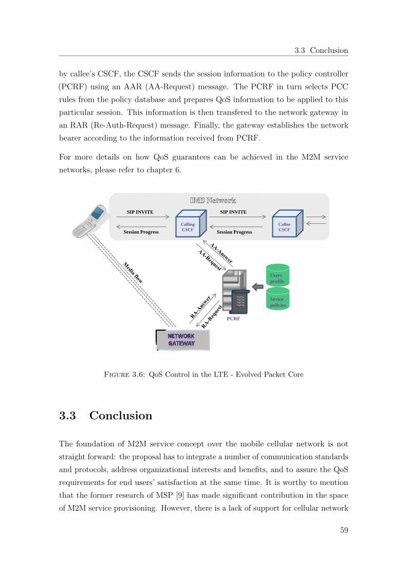
3.3 Conclusion
by callee’s CSCF, the CSCF sends the session information to the policy controller
(PCRF) using an AAR (AA-Request) message. The PCRF in turn selects PCC
rules from the policy database and prepares QoS information to be applied to this
particular session. This information is then transfered to the network gateway in
an RAR (Re-Auth-Request) message. Finally, the gateway establishes the network
bearer according to the information received from PCRF.
For more details on how QoS guarantees can be achieved in the M2M service
networks, please refer to chapter 6.
Calling
CSCF
Callee
CSCF
SIP INVITE SIP INVITE
Session Progress Session Progress
³³33³³33 ³³33³³33 ³³33³³33 ³³33³³33
PCRF
Sevice
policies
Users
profile
Figure 3.6: QoS Control in the LTE - Evolved Packet Core
3.3 Conclusion
The foundation of M2M service concept over the mobile cellular network is not
straight forward: the proposal has to integrate a number of communication standards
and protocols, address organizational interests and benefits, and to assure the QoS
requirements for end users’ satisfaction at the same time. It is worthy to mention
that the former research of MSP [9] has made significant contribution in the space
of M2M service provisioning. However, there is a lack of support for cellular network
59
Chapter 3. IMS - Mobile Server Platform
interfaces, protocols and policy and charging mechanisms required to realize M2M
concept for telecom networks. Therefore, this chapter is dedicated to propose the
required modifications and extensions in the existing MSP for standardized M2M
service provisioning over the cellular operator network. The proposed solution is as
follows:
� A novel concept of Mobile Application Server (MobAS) has been introduced
in the operator’s LTE / IMS network for hosting M2M multimedia services
from the user handheld devices. Same as SIP ASs in the IMS network, the
proposed MobAS has the ability to register itself in the IMS network and
invoke multimedia sessions through standardized interfaces of the operator
network, if the operator permits to do so.
� From accessibility point of view, every MobAS will be assigned a static IP
address and port number in the DNS system of the operator network. How-
ever, in the current IMS testbed the assignment of IP addresses is a manual
process, which could a be tiresome process for bigger networks. Therefore, it
is recommended that IPs are assigned to the user profiles instead of individual
devices.
� The SIP protocol mappings are created with the REST messaging framework
of the MSP proposed in [9]. Some standardized M2M services such as text
messaging, file sharing and multimedia audio/video streaming are developed
as a part of extended framework. The architectural details of the proposed
messaging and streaming framework will be covered in chapter 4 and chapter
5.
� In order to ensure QoS provisioning of M2M multimedia services, an M2M
QoS framework (detailed architecture in chapter 6) is implemented following
the 3GPP Policy and Charging Control (PCC) standard.
60
Chapter 4
Mobile-to-Mobile Multimedia
Messaging Framework
This chapter enfolds the design and implementation of M2M messaging framework
of the MSP. The proposed instant messaging services such as text messaging and
file sharing support the standardized protocols and interfaces of the IMS network.
The proposed architecture is aimed to conform to the functional and non-functional
requirements of the Instant Messaging (IM) service addressed by the 3GPP telecom
association. These requirements are summarized in section 4.1.1. Furthermore, the
chapter provides the performance evaluation of the newly implemented services. The
work presented in this chapter is mainly based on the author contribution in [21, 20].
Moreover, a master thesis guided by the author [57] has elaborated implementation
details and conducted some additional measurements.
4.1 Instant Messaging in IMS
Instant Messaging (IM) is known as one of the most popular services among users
to share content in near-real time. The content in an IM could be a text, an
image, an audio or a video clip. 3GPP specifies the requirements for ASs and the
IMS terminals to enable support for IM for information exchange. The IM service
combines perfectly with the presence service as users know when the friends are
online and can start messaging conversation [28, 3].
61
Chapter 4. Mobile-to-Mobile Multimedia Messaging Framework
There are two modes of IM in the IMS: pager mode and the session-based mode.
Pager mode came with the introduction of IMS in 3GPP release 5. Pager mode
instant message is short message with limited data capacity and has no connection
with any other messages. The pager mode contains the basic requirement for the
application servers to be able to send short IM to the IMS terminal. Pager mode
IM is similar to Short Message Service (SMS) in the cellular network. It uses the
IETF extension which consists of a SIP method called MESSAGE. This MESSAGE
method can carry any type of payload in the body of the message, if formatted with
an appropriate MIME type [5].
Release 6 of the 3GPP specifications for the IMS introduced session based IM in the
IMS network. SIP INVITE method is used to establish the session. The Message
Session Relay Protocol (MSRP) is used to transport the messages in the IMS. The
MSRP is implemented in the IMS terminals. MSRP runs over the media plane,
which comprises of the operator’s network gateway and involves no IMS SIP proxy
in between sending and receiving devices. In other words, the MSRP messages need
not traverse SIP proxies. This is a benefit since SIP proxies are not bothered with
proxying large instant messages.
4.1.1 Instant Messaging Requirements in IMS/LTE Net-
work
The 3GPP specification for IM defines some implementation requirements for the
pager-mode and session based IM. In the scope of the dissertation, some key re-
quirements are identified and discussed below. However, the complete set of 3GPP
requirements can be found in 3GPP TS 22.340 [5].
Interoperability The network operators have different network configurations and
commercial requirements, hence, IMS messaging shall be supported in a manner
to meet the IMS requirements of the operator and thus the standardized set of
functionalities must ensure interoperability across different networks and terminals
supporting IMS messaging.
Differentiation There shall be a mechanism to differentiate session based mes-
saging from other messaging types. The functionalities included in session based
messaging must ensure interoperability between different terminals and networks.
62
4.2 Instant Messaging in IMS
Terminal capabilities When including the participants in the messaging session
the terminal capabilities must be taken into account like the display capabilities,
media content types and media content formats supported by the device, media
storage capacity and the encryption and security mechanisms supported by the
terminal.
Session properties The subscriber should be able to request the message session
properties.
QoS control The network operator providing the IMS messaging service shall be
given the possibility to choose, wherever possible, the QoS parameters and also be
able to enforce the preferred transport mechanism and parameters both for the UE
originated and UE terminated messages.
Messaging content Regarding the message content, 3GPP specifies that the
content size shall not be limited and it should be possible to carry different media
including text, audio, video and images and the media types shall be MIME encoded.
Session based messaging shall use a minimum set of supported formats to ensure
interoperability between different networks and terminals and these formats shall be
common to all IMS messaging types. The content formats shall be aligned to enable
interworking with the 3GPP and Internet messaging solutions. It shall be possible
to compose a message of multi-media (e.g. voice and video).
Enable and disable messaging IMS messaging shall be able to support a request
from the service provider to enable or disable message delivery and submission and
similarly, it shall also support a request from the user to enable or disable message
delivery and submission.
Customization The user shall be able to manage his service profile related to the
IMS messaging that means the user can customize his messaging environment within
the capabilities of the messaging application, terminal and the network.
Acknowledgments The messages are transported by the IMS network to the
recipient’s terminal and the sender can receive the service delivery acknowledgments
for the messages sent by him.
63
Chapter 4. Mobile-to-Mobile Multimedia Messaging Framework
4.2 Realization of M2M Instant Messaging
This section explains how the Mobile Server Platform (MSP) is utilized to realize an
M2M instant messaging over the operator IMS network. Imagine the chat messaging
session between two mobile users, Bob (A1) and Alice (A2), as discussed in section
3.2.2.3. As Figure 3.5 depicts that both users exchange a couple of short SIP
messages until Bob wants Alice to send him a picture. Alice picks a picture from the
picture gallery and presses Ok to send. In response to OK, the Alice’s MSP sends a
short SIP message to Bob’s MSP in order to have its permission to receive an image
file. After receiving a 200 OK message from Bob’s MSP, Alice MSP creates a SIP
INVITE session with Bob’s MSP and the actual image transfer starts.
In the above scenario, the communication between two end points can be categorized
in two different forms: short term messages (like pager mode IM) such as text
messaging in the start of the conversation and long term messages (like session
based IM) such as multimedia file transfer. Hence, the following sections enfold the
implementation of these two messaging types.
4.2.1 Text Messaging
As mentioned earlier that MSP supports two different types of service invocation
mechanisms: synchronous and asynchronous. The text messaging service is imple-
mented by synchronous invocation mechanism of MSP. The service allows an IMS
user to send simple chat messages to other registered users in the network. It only
requires the message content and the destination address in order to send a message
to the destination user. The user is notified after the message is successfully sent.
Hence, in case of any SIP MESSAGE received by the MSP, a synchronous service
is invoked which reads the message and sends a 200 OK message in response. In
general, any kind of SIP request that follows a request-response approach can be
implemented by the synchronous mechanism of MSP.
Figure 4.1 depicts the signaling flow of SIP MESSAGE request from one MSP to
another. Whenever a SIP Message reaches an IMS network, two major operations
are performed by the network entities. First, a Diameter request-response operation
is performed by I-CSCF in order to verify the subscription of the mobile user. The
64
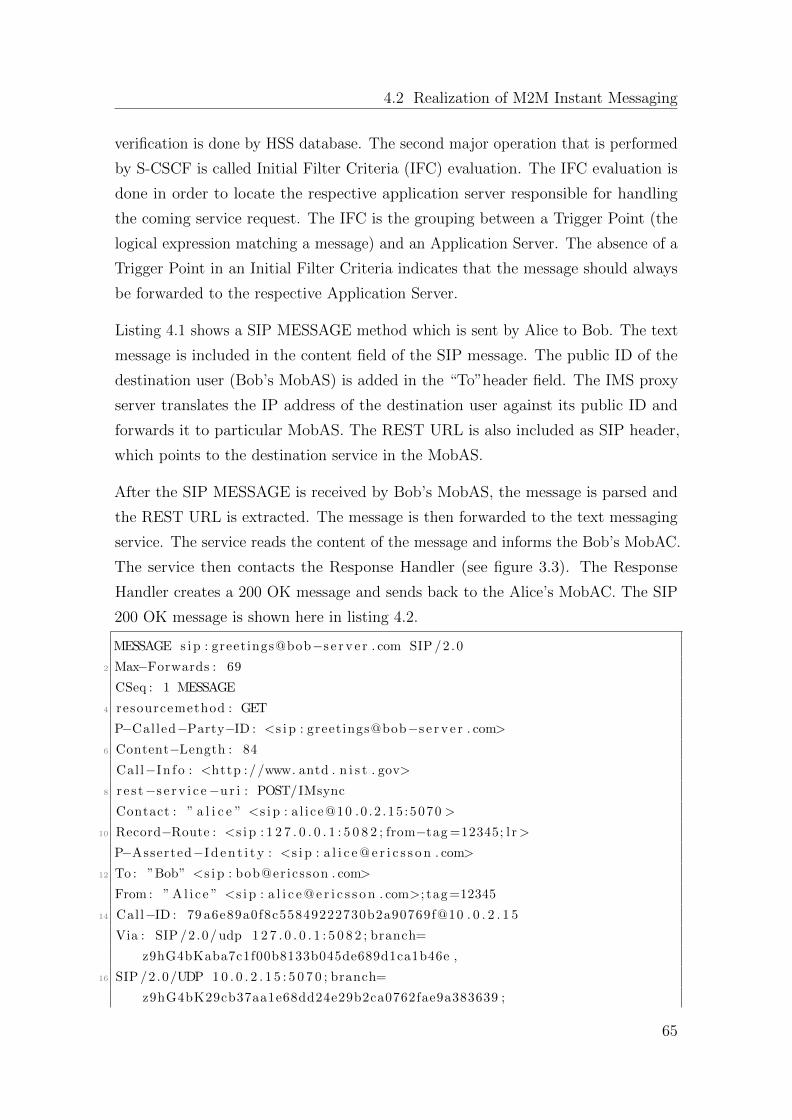
4.2 Realization of M2M Instant Messaging
verification is done by HSS database. The second major operation that is performed
by S-CSCF is called Initial Filter Criteria (IFC) evaluation. The IFC evaluation is
done in order to locate the respective application server responsible for handling
the coming service request. The IFC is the grouping between a Trigger Point (the
logical expression matching a message) and an Application Server. The absence of a
Trigger Point in an Initial Filter Criteria indicates that the message should always
be forwarded to the respective Application Server.
Listing 4.1 shows a SIP MESSAGE method which is sent by Alice to Bob. The text
message is included in the content field of the SIP message. The public ID of the
destination user (Bob’s MobAS) is added in the “To”header field. The IMS proxy
server translates the IP address of the destination user against its public ID and
forwards it to particular MobAS. The REST URL is also included as SIP header,
which points to the destination service in the MobAS.
After the SIP MESSAGE is received by Bob’s MobAS, the message is parsed and
the REST URL is extracted. The message is then forwarded to the text messaging
service. The service reads the content of the message and informs the Bob’s MobAC.
The service then contacts the Response Handler (see figure 3.3). The Response
Handler creates a 200 OK message and sends back to the Alice’s MobAC. The SIP
200 OK message is shown here in listing 4.2.
MESSAGE s i p : greetings@bob−s e r v e r . com SIP /2 .0
2 Max−Forwards : 69
CSeq : 1 MESSAGE
4 resourcemethod : GET
P−Called−Party−ID : <s i p : greetings@bob−s e r v e r . com>
6 Content−Length : 84
Cal l−In f o : <http ://www. antd . n i s t . gov>
8 r e s t−s e r v i c e−u r i : POST/IMsync
Contact : ” a l i c e ” <s i p : a l i ce@10 .0 .2 .15 :5070 >
10 Record−Route : <s i p : 1 2 7 . 0 . 0 . 1 : 5 0 8 2 ; from−tag =12345; l r>
P−Asserted−I d e n t i t y : <s i p : a l i c e @ e r i c s s o n . com>
12 To : ”Bob” <s i p : bob@ericsson . com>
From : ” A l i c e ” <s i p : a l i c e @ e r i c s s o n . com>; tag =12345
14 Call−ID : 79 a6e89a0f8c55849222730b2a90769f@10 . 0 . 2 . 1 5
Via : SIP /2 .0/ udp 1 2 7 . 0 . 0 . 1 : 5 0 8 2 ; branch=
z9hG4bKaba7c1f00b8133b045de689d1ca1b46e ,
16 SIP /2 .0/UDP 1 0 . 0 . 2 . 1 5 : 5 0 7 0 ; branch=
z9hG4bK29cb37aa1e68dd24e29b2ca0762fae9a383639 ;
65
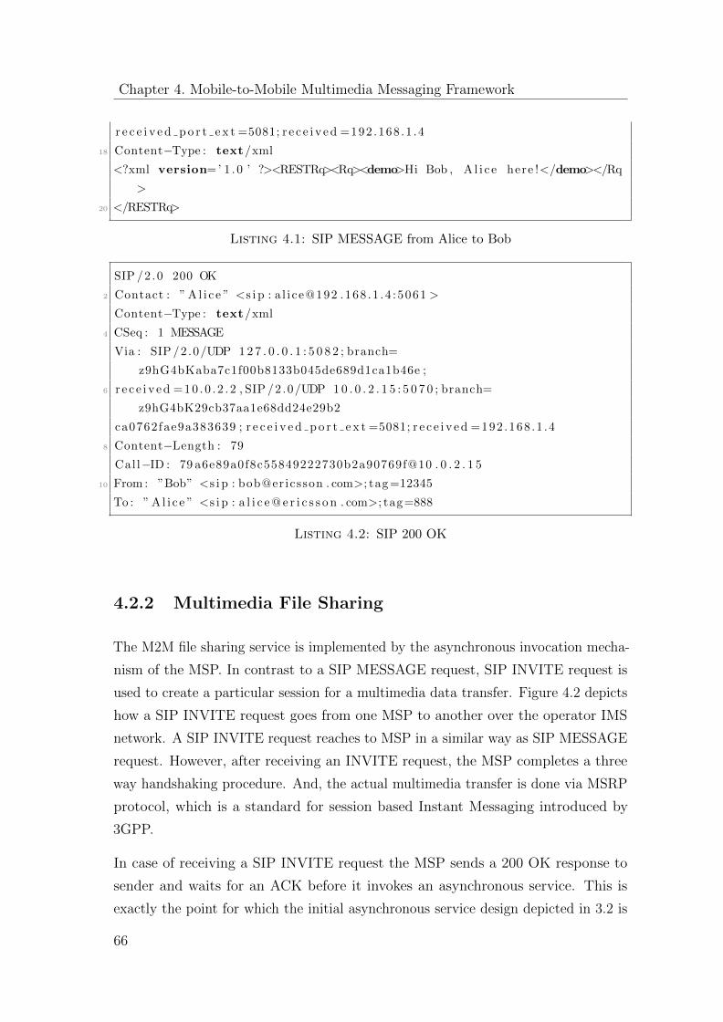
Chapter 4. Mobile-to-Mobile Multimedia Messaging Framework
r e c e i v e d p o r t e x t =5081; r e c e i v e d =192 .168 .1 .4
18 Content−Type : text/xml
<?xml version=’ 1 .0 ’ ?><RESTRq><Rq><demo>Hi Bob , A l i c e here !</demo></Rq
>
20 </RESTRq>
Listing 4.1: SIP MESSAGE from Alice to Bob
SIP /2 .0 200 OK
2 Contact : ” A l i c e ” <s i p : a l i ce@192 .168 .1 .4 :5061 >
Content−Type : text/xml
4 CSeq : 1 MESSAGE
Via : SIP /2 .0/UDP 1 2 7 . 0 . 0 . 1 : 5 0 8 2 ; branch=
z9hG4bKaba7c1f00b8133b045de689d1ca1b46e ;
6 r e c e i v e d =10 .0 . 2 . 2 , SIP /2 .0/UDP 1 0 . 0 . 2 . 1 5 : 5 0 7 0 ; branch=
z9hG4bK29cb37aa1e68dd24e29b2
ca0762fae9a383639 ; r e c e i v e d p o r t e x t =5081; r e c e i v e d =192 .168 .1 .4
8 Content−Length : 79
Cal l−ID : 79 a6e89a0f8c55849222730b2a90769f@10 . 0 . 2 . 1 5
10 From : ”Bob” <s i p : bob@ericsson . com>; tag =12345
To : ” A l i c e ” <s i p : a l i c e @ e r i c s s o n . com>; tag=888
Listing 4.2: SIP 200 OK
4.2.2 Multimedia File Sharing
The M2M file sharing service is implemented by the asynchronous invocation mecha-
nism of the MSP. In contrast to a SIP MESSAGE request, SIP INVITE request is
used to create a particular session for a multimedia data transfer. Figure 4.2 depicts
how a SIP INVITE request goes from one MSP to another over the operator IMS
network. A SIP INVITE request reaches to MSP in a similar way as SIP MESSAGE
request. However, after receiving an INVITE request, the MSP completes a three
way handshaking procedure. And, the actual multimedia transfer is done via MSRP
protocol, which is a standard for session based Instant Messaging introduced by
3GPP.
In case of receiving a SIP INVITE request the MSP sends a 200 OK response to
sender and waits for an ACK before it invokes an asynchronous service. This is
exactly the point for which the initial asynchronous service design depicted in 3.2 is
66
4.2 Realization of M2M Instant Messaging
P-CSCF I-CSCF S-CSCF
MESSAGE
MESSAGE Diameter Rq
(LIR)
Diameter Rs
(LIA) MESSAGE
MESSAGE
200 OK
200 OK
200 OK
200 OK
MSP
(Application Client)
MSP
(Application Server)
IFC Evaluation
IM service
invocation
HSS
Figure 4.1: SIP MESSAGE Flow
extended in a way to support an additional notification message (ACK) from client
to server after an INVITE request is sent and response (200 OK) is received.
The discussion of the asynchronous file sharing service is further divided into two
major phases: session establishment phase and media delivery phase.
4.2.2.1 Session Establishment Phase
The SIP INVITE request is sent by Alice with the public SIP address of the
destination MobAS. In this case it would be [email protected]. This SIP
INVITE request message reaches the IMS proxy server CSCF. The CSCF checks the
DNS and finds the IP against the requested server ”bob-server.ericsson.com”. The
SIP INVITE request is then forwarded to that address. The SIP INVITE method
also contains the contact header in which the IP and port is specified where ’Alice’
wants to receive the response. A sample SIP INVITE is shown in the listing 4.3.
1 INVITE s i p : greetings@bob−s e r v e r . com SIP /2 .0
Max−Forwards : 69
67

Chapter 4. Mobile-to-Mobile Multimedia Messaging Framework
P-CSCF I-CSCF S-CSCF
INVITE
INVITE Diameter Rq
(LIR)
Diameter Rs
(LIA) INVITE
INVITE
180 Ringing
MSP
(Application Client)
MSP
(Application Server)
IFC Evaluation
IM service
invocation
HSS
100 Trying
100 Trying
100 Trying
100 Trying
180 Ringing 180 Ringing
180 Ringing
200 Ok 200 Ok
200 Ok 200 Ok
ACK ACK
ACK ACK
MSRP: SEND
200 Ok
MSRP: SEND
200 Ok
Figure 4.2: SIP INVITE Flow
3 CSeq : 1 INVITE
resourcemethod : GET
5 P−Called−Party−ID : <s i p : greetings@bob−s e r v e r . com>
Content−Length : 751
7 Call−In f o : <http ://www. antd . n i s t . gov>
r e s t−s e r v i c e−u r i : POST/Request−Response/ Factory / create InstanceRq /
IMasync/add
9 Contact : ” A l i c e ” <s i p : a l i ce@10 .0 .2 .15 :5071 >
Record−Route : <s i p : 1 2 7 . 0 . 0 . 1 : 5 0 8 2 ; from−tag =12345; l r>
11 P−Asserted−I d e n t i t y : <s i p : a l i c e @ e r i c s s o n . com>
To : ”Bob” <s i p : bob@ericsson . com>
13 From : ” Al i c e ” <s i p : a l i c e @ e r i c s s o n . com>; tag =12345
my−other−header : my new header va lue
15 Call−ID : 37 c08f9666a687a3027ac22b98483158@10 . 0 . 2 . 1 5
Content−Type : a p p l i c a t i o n /sdp
17 Via : SIP /2 .0/ udp 1 2 7 . 0 . 0 . 1 : 5 0 8 2 ; branch=
z9hG4bK4a2b443a5792a53b7d13c83662dd87cf ,
SIP /2 .0/UDP 1 0 . 0 . 2 . 1 5 : 5 0 7 1 ; branch=
z9hG4bK3054372ee7534b8d107a936cd29931e1393030 ;
19 r e c e i v e d p o r t e x t =5081; r e c e i v e d =192 .168 .1 .4
68
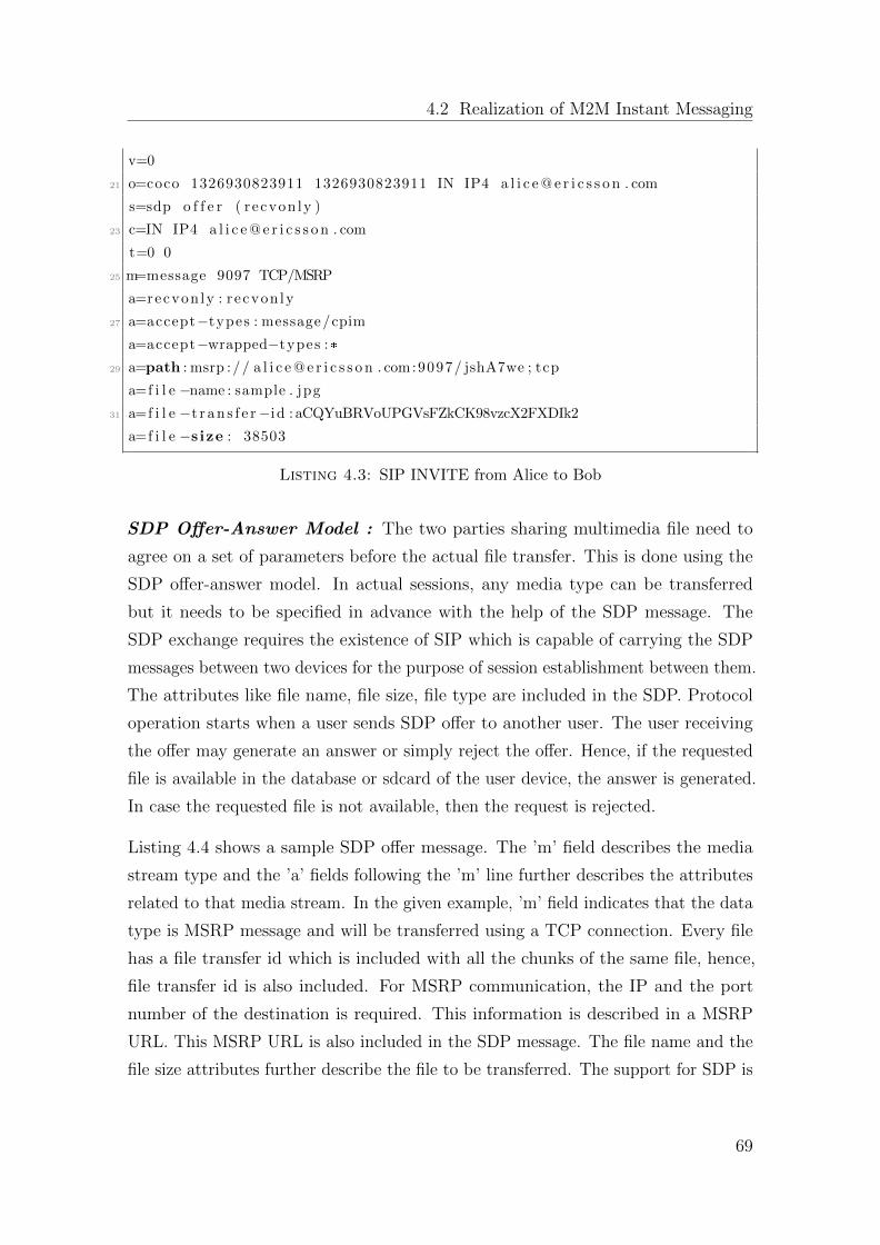
4.2 Realization of M2M Instant Messaging
v=0
21 o=coco 1326930823911 1326930823911 IN IP4 a l i c e @ e r i c s s o n . com
s=sdp o f f e r ( r ecvon ly )
23 c=IN IP4 a l i c e @ e r i c s s o n . com
t=0 0
25 m=message 9097 TCP/MSRP
a=recvon ly : r ecvon ly
27 a=accept−types : message/cpim
a=accept−wrapped−types :*
29 a=path : msrp :// a l i c e @ e r i c s s o n . com:9097/ jshA7we ; tcp
a=f i l e −name : sample . jpg
31 a=f i l e −t r a n s f e r−id : aCQYuBRVoUPGVsFZkCK98vzcX2FXDIk2
a=f i l e −s ize : 38503
Listing 4.3: SIP INVITE from Alice to Bob
SDP Offer-Answer Model : The two parties sharing multimedia file need to
agree on a set of parameters before the actual file transfer. This is done using the
SDP offer-answer model. In actual sessions, any media type can be transferred
but it needs to be specified in advance with the help of the SDP message. The
SDP exchange requires the existence of SIP which is capable of carrying the SDP
messages between two devices for the purpose of session establishment between them.
The attributes like file name, file size, file type are included in the SDP. Protocol
operation starts when a user sends SDP offer to another user. The user receiving
the offer may generate an answer or simply reject the offer. Hence, if the requested
file is available in the database or sdcard of the user device, the answer is generated.
In case the requested file is not available, then the request is rejected.
Listing 4.4 shows a sample SDP offer message. The ’m’ field describes the media
stream type and the ’a’ fields following the ’m’ line further describes the attributes
related to that media stream. In the given example, ’m’ field indicates that the data
type is MSRP message and will be transferred using a TCP connection. Every file
has a file transfer id which is included with all the chunks of the same file, hence,
file transfer id is also included. For MSRP communication, the IP and the port
number of the destination is required. This information is described in a MSRP
URL. This MSRP URL is also included in the SDP message. The file name and the
file size attributes further describe the file to be transferred. The support for SDP is
69
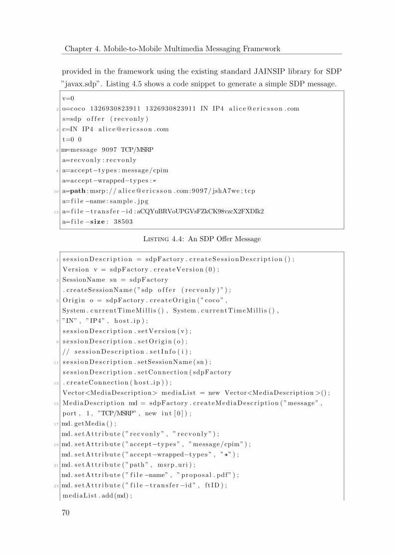
Chapter 4. Mobile-to-Mobile Multimedia Messaging Framework
provided in the framework using the existing standard JAINSIP library for SDP
”javax.sdp”. Listing 4.5 shows a code snippet to generate a simple SDP message.
v=0
2 o=coco 1326930823911 1326930823911 IN IP4 a l i c e @ e r i c s s o n . com
s=sdp o f f e r ( r ecvon ly )
4 c=IN IP4 a l i c e @ e r i c s s o n . com
t=0 0
6 m=message 9097 TCP/MSRP
a=recvon ly : r ecvon ly
8 a=accept−types : message/cpim
a=accept−wrapped−types :*
10 a=path : msrp :// a l i c e @ e r i c s s o n . com:9097/ jshA7we ; tcp
a=f i l e −name : sample . jpg
12 a=f i l e −t r a n s f e r−id : aCQYuBRVoUPGVsFZkCK98vzcX2FXDIk2
a=f i l e −s ize : 38503
Listing 4.4: An SDP Offer Message
1 s e s s i o n D e s c r i p t i o n = sdpFactory . c r e a t e S e s s i o n D e s c r i p t i o n ( ) ;
Vers ion v = sdpFactory . c r ea t eVer s i on (0 ) ;
3 SessionName sn = sdpFactory
. createSess ionName ( ”sdp o f f e r ( recvon ly ) ” ) ;
5 Orig in o = sdpFactory . c r e a t e O r i g i n ( ” coco ” ,
System . cur rentT imeMi l l i s ( ) , System . cur rentT imeMi l l i s ( ) ,
7 ”IN” , ”IP4” , h o s t i p ) ;
s e s s i o n D e s c r i p t i o n . s e tVer s i on ( v ) ;
9 s e s s i o n D e s c r i p t i o n . s e t O r i g i n ( o ) ;
// s e s s i o n D e s c r i p t i o n . s e t I n f o ( i ) ;
11 s e s s i o n D e s c r i p t i o n . setSessionName ( sn ) ;
s e s s i o n D e s c r i p t i o n . setConnect ion ( sdpFactory
13 . c reateConnect ion ( h o s t i p ) ) ;
Vector<MediaDescr ipt ion> mediaList = new Vector<MediaDescr ipt ion >() ;
15 MediaDescr ipt ion md = sdpFactory . c reateMed iaDescr ipt ion ( ”message” ,
port , 1 , ”TCP/MSRP” , new i n t [ 0 ] ) ;
17 md. getMedia ( ) ;
md. s e t A t t r i b u t e ( ” recvon ly ” , ” recvon ly ” ) ;
19 md. s e t A t t r i b u t e ( ” accept−types ” , ”message/cpim” ) ;
md. s e t A t t r i b u t e ( ” accept−wrapped−types ” , ”*” ) ;
21 md. s e t A t t r i b u t e ( ”path” , msrp ur i ) ;
md. s e t A t t r i b u t e ( ” f i l e −name” , ” proposa l . pdf ” ) ;
23 md. s e t A t t r i b u t e ( ” f i l e −t r a n s f e r−id ” , f t ID ) ;
mediaList . add (md) ;
70
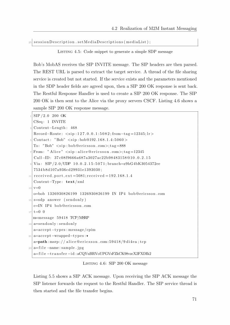
4.2 Realization of M2M Instant Messaging
25 s e s s i o n D e s c r i p t i o n . s e tMed iaDesc r ip t i ons ( mediaList ) ;
Listing 4.5: Code snippet to generate a simple SDP message
Bob’s MobAS receives the SIP INVITE message. The SIP headers are then parsed.
The REST URL is parsed to extract the target service. A thread of the file sharing
service is created but not started. If the service exists and the parameters mentioned
in the SDP header fields are agreed upon, then a SIP 200 OK response is sent back.
The Restful Response Handler is used to create a SIP 200 OK response. The SIP
200 OK is then sent to the Alice via the proxy servers CSCF. Listing 4.6 shows a
sample SIP 200 OK response message.
1 SIP /2 .0 200 OK
CSeq : 1 INVITE
3 Content−Length : 468
Record−Route : <s i p : 1 2 7 . 0 . 0 . 1 : 5 0 8 2 ; from−tag =12345; l r>
5 Contact : ”Bob” <s i p : bob@192 .168 .1 .4 :5060 >
To : ”Bob” <s i p : bob@ericsson . com>; tag=888
7 From : ” A l i c e ” <s i p : a l i c e @ e r i c s s o n . com>; tag =12345
Call−ID : 37 c08f9666a687a3027ac22b98483158@10 . 0 . 2 . 1 5
9 Via : SIP /2 .0/UDP 1 0 . 0 . 2 . 1 5 : 5 0 7 1 ; branch=z9hG4bK3054372ee
7534 b8d107a936cd29931e1393030 ;
11 r e c e i v e d p o r t e x t =5081; r e c e i v e d =192 .168 .1 .4
Content−Type : text/xml
13 v=0
o=bob 1326930826199 1326930826199 IN IP4 bob@ericsson . com
15 s=sdp answer ( sendonly )
c=IN IP4 bob@ericsson . com
17 t=0 0
m=message 59418 TCP/MSRP
19 a=sendonly : sendonly
a=accept−types : message/cpim
21 a=accept−wrapped−types :*
a=path : msrp :// a l i c e @ e r i c s s o n . com:59418/9 di4ea ; tcp
23 a=f i l e −name : sample . jpg
a=f i l e −t r a n s f e r−id : aCQYuBRVoUPGVsFZkCK98vzcX2FXDIk2
Listing 4.6: SIP 200 OK message
Listing 5.5 shows a SIP ACK message. Upon receiving the SIP ACK message the
SIP listener forwards the request to the Restful Handler. The SIP service thread is
then started and the file transfer begins.
71
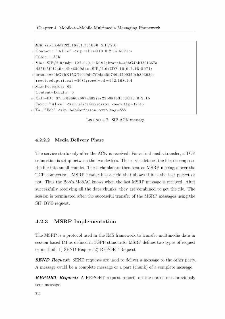
Chapter 4. Mobile-to-Mobile Multimedia Messaging Framework
ACK s i p : bob@192 . 1 6 8 . 1 . 4 : 5 0 6 0 SIP /2 .0
2 Contact : ” A l i c e ” <s i p : a l i ce@10 .0 .2 .15 :5071 >
CSeq : 1 ACK
4 Via : SIP /2 .0/ udp 1 2 7 . 0 . 0 . 1 : 5 0 8 2 ; branch=z9hG4bKf391367a
d35fe5 f9 f2a0eedbc6509d4e , SIP /2 .0/UDP 1 0 . 0 . 2 . 1 5 : 5 0 7 1 ;
6 branch=z9hG4bK153ff16e9db7f0dab5d749bf709250cb393030 ;
r e c e i v e d p o r t e x t =5081; r e c e i v e d =192 .168 .1 .4
8 Max−Forwards : 69
Content−Length : 0
10 Call−ID : 37 c08f9666a687a3027ac22b98483158@10 . 0 . 2 . 1 5
From : ” Al i c e ” <s i p : a l i c e @ e r i c s s o n . com>; tag =12345
12 To : ”Bob” <s i p : bob@ericsson . com>; tag=888
Listing 4.7: SIP ACK message
4.2.2.2 Media Delivery Phase
The service starts only after the ACK is received. For actual media transfer, a TCP
connection is setup between the two devices. The service fetches the file, decomposes
the file into small chunks. These chunks are then sent as MSRP messages over the
TCP connection. MSRP header has a field that shows if it is the last packet or
not. Thus the Bob’s MobAC knows when the last MSRP message is received. After
successfully receiving all the data chunks, they are combined to get the file. The
session is terminated after the successful transfer of the MSRP messages using the
SIP BYE request.
4.2.3 MSRP Implementation
The MSRP is a protocol used in the IMS framework to transfer multimedia data in
session based IM as defined in 3GPP standards. MSRP defines two types of request
or method: 1) SEND Request 2) REPORT Request
SEND Request: SEND requests are used to deliver a message to the other party.
A message could be a complete message or a part (chunk) of a complete message.
REPORT Request: A REPORT request reports on the status of a previously
sent message.
72
4.2 Realization of M2M Instant Messaging
In contrast to the individual messages sent in the pager-mode IM, the session based
IM contains a series of exchange of messages with a definite start and a definite
end. Session based IM has quite many advantages over the pager-mode IM including
tighter integration with different media-types, direct client to client communication,
and brokered privacy and security.
Several open-source libraries for implementation of the MSRP are found. But no
proper documentation or tutorial is available on the use of these MSRP libraries.
Therefore, a customized functionality of the MSRP with respect to the file sharing
scenario is implemented from scratch. The written MSRP class follows the IETF
standard [29] in order to achieve the following functionalities:
� Converting the byte array of the given file data to small chunks of fixed size.
� Adding MSRP headers to the individual chunks depending on the chunk
number.
� Getting a received chunk information included if the chunk is the last one or
not.
� An MSRP parser in order to read an MSRP message and extract the payload.
A typical MSRP request contains an MSRP URI, which is used to identify a session
of instant messages at a particular MSRP device, as well as to identify an MSRP
relay in general. An MSRP URI follows a scheme as define in Reference RFC 3986
[25], which holds the IP/ domain name and port, the session identifier, the transport
method and additional optional parameters. Listing 4.8 shows a sample MSRP
SEND request. Here msrp://[email protected]:9097asaO6sdkht;tcp is an example
URI, where:
� msrp is the scheme, it can also be msrps
� [email protected] is the domain
� 9097 is the port where it want to get the requests on the IP of the above
domain
� asaO6sdkhto is the session identifier
� tcp is the transport.
73
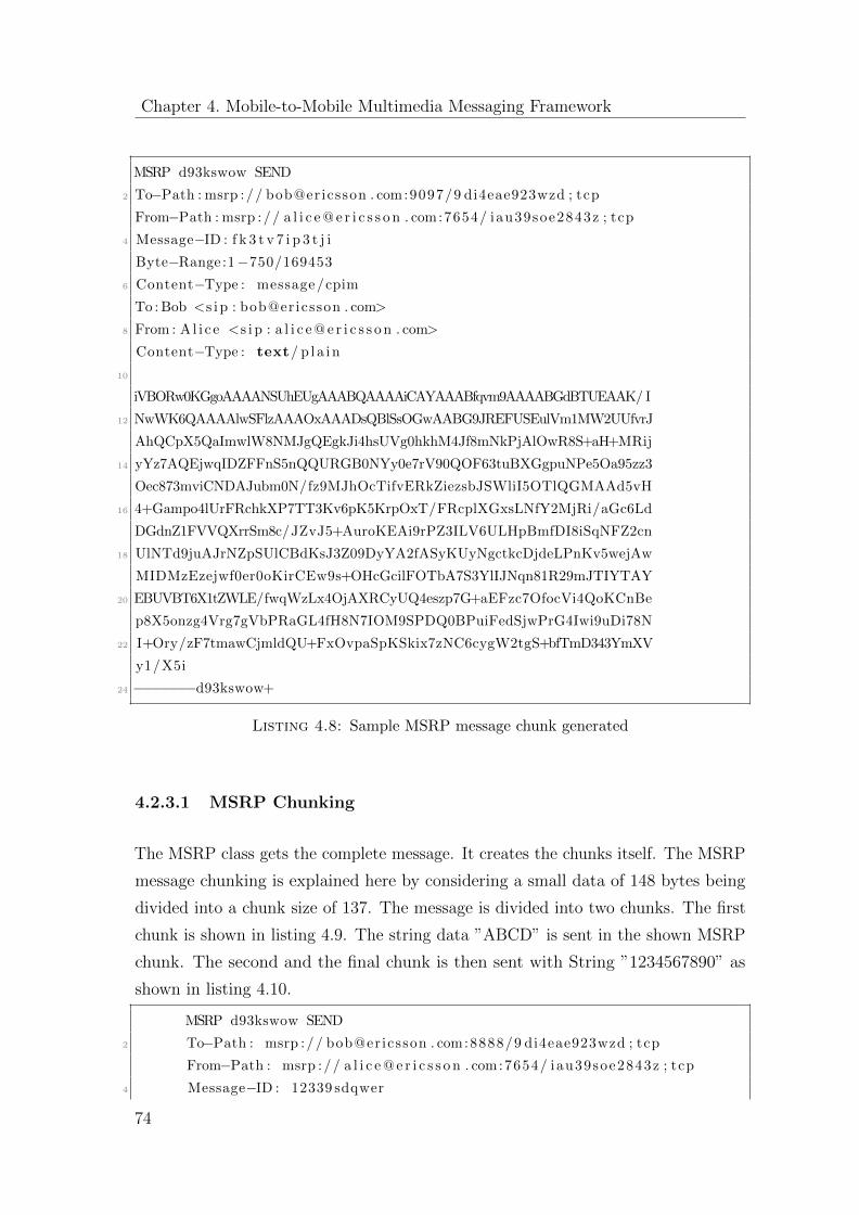
Chapter 4. Mobile-to-Mobile Multimedia Messaging Framework
MSRP d93kswow SEND
2 To−Path : msrp :// bob@ericsson . com:9097/9 di4eae923wzd ; tcp
From−Path : msrp :// a l i c e @ e r i c s s o n . com:7654/ iau39soe2843z ; tcp
4 Message−ID : f k 3 t v 7 i p 3 t j i
Byte−Range :1−750/169453
6 Content−Type : message/cpim
To : Bob <s i p : bob@ericsson . com>
8 From : A l i c e <s i p : a l i c e @ e r i c s s o n . com>
Content−Type : text/ p l a in
10
iVBORw0KGgoAAAANSUhEUgAAABQAAAAiCAYAAABfqvm9AAAABGdBTUEAAK/ I
12 NwWK6QAAAAlwSFlzAAAOxAAADsQBlSsOGwAABG9JREFUSEulVm1MW2UUfvrJ
AhQCpX5QaImwlW8NMJgQEgkJi4hsUVg0hkhM4Jf8mNkPjAlOwR8S+aH+MRij
14 yYz7AQEjwqIDZFFnS5nQQURGB0NYy0e7rV90QOF63tuBXGgpuNPe5Oa95zz3
Oec873mviCNDAJubm0N/fz9MJhOcTifvERkZiezsbJSWliI5OTlQGMAAd5vH
16 4+Gampo4lUrFRchkXP7TT3Kv6pK5KrpOxT/FRcplXGxsLNfY2MjRi/aGc6Ld
DGdnZ1FVVQXrrSm8c/JZvJ5+AuroKEAi9rPZ3ILV6ULHpBmfDI8iSqNFZ2cn
18 UlNTd9juAJrNZpSUlCBdKsJ3Z09DyYA2fASyKUyNgctkcDjdeLPnKv5wejAw
MIDMzEzejwf0er0oKirCEw9s+OHcGcilFOTbA7S3YlIJNqn81R29mJTIYTAY
20 EBUVBT6X1tZWLE/fwqWzLx4OjAXRCyUQ4eszp7G+aEFzc7OfocVi4QoKCnBe
p8X5onzg4Vrg7gVbPRaGL4fH8N7IOM9SPDQ0BPuiFedSjwPrG4Iwi9uDi78N
22 I+Ory/zF7tmawCjmldQU+FxOvpaSpKSkix7zNC6cygW2tgS+bfTmD343YmXV
y1/X5i
24 −−−−−−−d93kswow+
Listing 4.8: Sample MSRP message chunk generated
4.2.3.1 MSRP Chunking
The MSRP class gets the complete message. It creates the chunks itself. The MSRP
message chunking is explained here by considering a small data of 148 bytes being
divided into a chunk size of 137. The message is divided into two chunks. The first
chunk is shown in listing 4.9. The string data ”ABCD” is sent in the shown MSRP
chunk. The second and the final chunk is then sent with String ”1234567890” as
shown in listing 4.10.
MSRP d93kswow SEND
2 To−Path : msrp :// bob@ericsson . com:8888/9 di4eae923wzd ; tcp
From−Path : msrp :// a l i c e @ e r i c s s o n . com:7654/ iau39soe2843z ; tcp
4 Message−ID : 12339 sdqwer
74
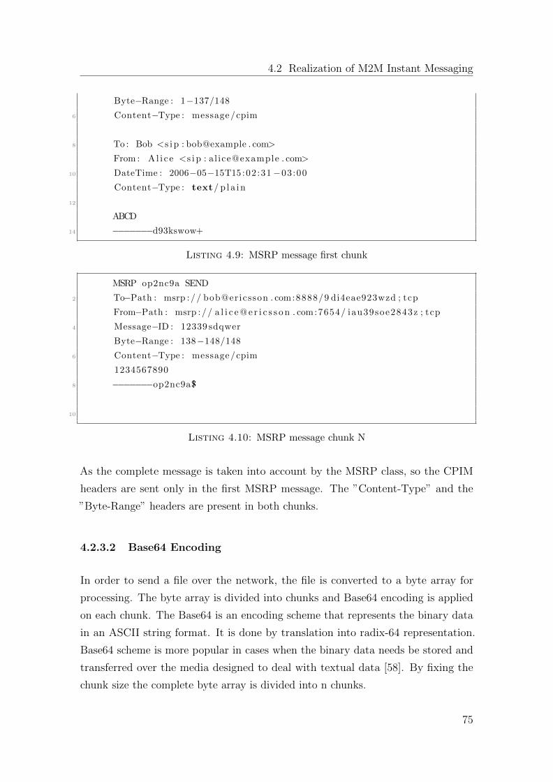
4.2 Realization of M2M Instant Messaging
Byte−Range : 1−137/148
6 Content−Type : message/cpim
8 To : Bob <s i p : bob@example . com>
From : A l i c e <s i p : a l ice@example . com>
10 DateTime : 2006−05−15T15 :02:31−03:00
Content−Type : text/ p l a in
12
ABCD
14 −−−−−−−d93kswow+
Listing 4.9: MSRP message first chunk
MSRP op2nc9a SEND
2 To−Path : msrp :// bob@ericsson . com:8888/9 di4eae923wzd ; tcp
From−Path : msrp :// a l i c e @ e r i c s s o n . com:7654/ iau39soe2843z ; tcp
4 Message−ID : 12339 sdqwer
Byte−Range : 138−148/148
6 Content−Type : message/cpim
1234567890
8 −−−−−−−op2nc9a$
10
Listing 4.10: MSRP message chunk N
As the complete message is taken into account by the MSRP class, so the CPIM
headers are sent only in the first MSRP message. The ”Content-Type” and the
”Byte-Range” headers are present in both chunks.
4.2.3.2 Base64 Encoding
In order to send a file over the network, the file is converted to a byte array for
processing. The byte array is divided into chunks and Base64 encoding is applied
on each chunk. The Base64 is an encoding scheme that represents the binary data
in an ASCII string format. It is done by translation into radix-64 representation.
Base64 scheme is more popular in cases when the binary data needs be stored and
transferred over the media designed to deal with textual data [58]. By fixing the
chunk size the complete byte array is divided into n chunks.
75
Chapter 4. Mobile-to-Mobile Multimedia Messaging Framework
n = filesize/chunksize + 1
Keeping the chunk size equal to 720 bytes, the byte array divided into ’n’ number
of smaller byte arrays. Then MSRP headers are added to each chunk. The MSRP
header contains the information like message ID, session ID, content-type, byte
range out of the total bytes to be sent and the information whether this is the last
chunk or more chunks are to follow. After the successful chunking of the data into n
number of MSRP chunks, the service is informed that the chunks are ready to be
transferred.
4.2.3.3 MSRP Parser
The MSRP parser gets the MSRP message. The MSRP headers are parsed here
and the content is processed accordingly. The headers are removed and the media
content is extracted from the message. The MSRP parser distinguishes a MSRP
message chunk of one file from chunks of other transactions by the message identifier.
It knows from the headers when it receives the last chunk. The last byte of the
MSRP message has a value ’+’ or ’$’. The ’+’ indicates, more MSRP chunks to
follow and ’$’ indicates that this is the last MSRP chunk.
4.2.3.4 MSRP Response
Whenever a MSRP message is successfully received, the parser informs the Response
handler. Hence, the Response handler creates a 200 OK message and sends it back
to the sender. The sender waits for the 200 OK messages and sends the next MSRP
message only after it has received the MSRP 200 message. In case of any fault
occurred in the transfer, the sender gets a Transaction Timeout Exception, so the
previous MSRP chunk is sent again.
4.2.3.5 MSRP Ordering
A method is also written in the MSRP class to combine all the chunks and return
the complete message to the server.
76
4.3 Performance Evaluation
4.3 Performance Evaluation
The performance evaluation of the proposed framework has been extensively carried
out in order to study the processing latencies during the session establishment and
multimedia transfer phase. The testbed environment consists of two user terminals
and one server machine. The configuration of the testbed is as follows:
User Terminal -1 with MSP
Model: HTC Legend
Platform: Android 2.2
Camera: 5-megapixel color camera with auto focus and flash
Memory: ROM: 512MB RAM: 384MB
CPU Speed: 600MHz
User Terminal -2 with MSP
Model: Samsung Galaxy S3 (i900)
Platform: Android 4.1.2 (Jelly Bean)
Camera: 6-megapixel color camera with auto focus and flash
Memory: ROM: 16 GB RAM: 1 GB
CPU Speed: 1.4 GHz
Server Machine with IMS Testbed
Ericsson Service Development Studio is used as IMS testbed. It comes as an Eclipse
plug-in. It is running on the machine with the following specifications.
System Manufacturer: Acer
Model: Aspire 5551G
Processor: AMD Phenom II, X3 Mobile Processor
Speed: 2.1 GHz
Memory: RAM: 4GB
Operating System: Genuine Windows 7 Home Premium 64-bit.
Network Configurations
ADSL: G.992.5 (ADSL2+)
Download: 17393 Kbps
77
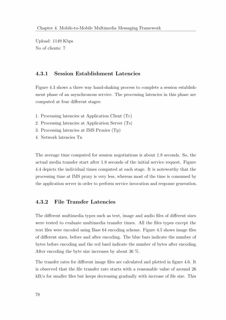
Chapter 4. Mobile-to-Mobile Multimedia Messaging Framework
Upload: 1149 Kbps
No of clients: 7
4.3.1 Session Establishment Latencies
Figure 4.3 shows a three way hand-shaking process to complete a session establish-
ment phase of an asynchronous service. The processing latencies in this phase are
computed at four different stages:
1. Processing latencies at Application Client (Tc)
2. Processing latencies at Application Server (Ts)
3. Processing latencies at IMS Proxies (Tp)
4. Network latencies Tn
The average time computed for session negotiations is about 1.8 seconds. So, the
actual media transfer start after 1.8 seconds of the initial service request. Figure
4.4 depicts the individual times computed at each stage. It is noteworthy that the
processing time at IMS proxy is very less, whereas most of the time is consumed by
the application server in order to perform service invocation and response generation.
4.3.2 File Transfer Latencies
The different multimedia types such as text, image and audio files of different sizes
were tested to evaluate multimedia transfer times. All the files types except the
text files were encoded using Base 64 encoding scheme. Figure 4.5 shows image files
of different sizes, before and after encoding. The blue bars indicate the number of
bytes before encoding and the red bard indicate the number of bytes after encoding.
After encoding the byte size increases by about 36 %.
The transfer rates for different image files are calculated and plotted in figure 4.6. It
is observed that the file transfer rate starts with a reasonable value of around 26
kB/s for smaller files but keeps decreasing gradually with increase of file size. This
78
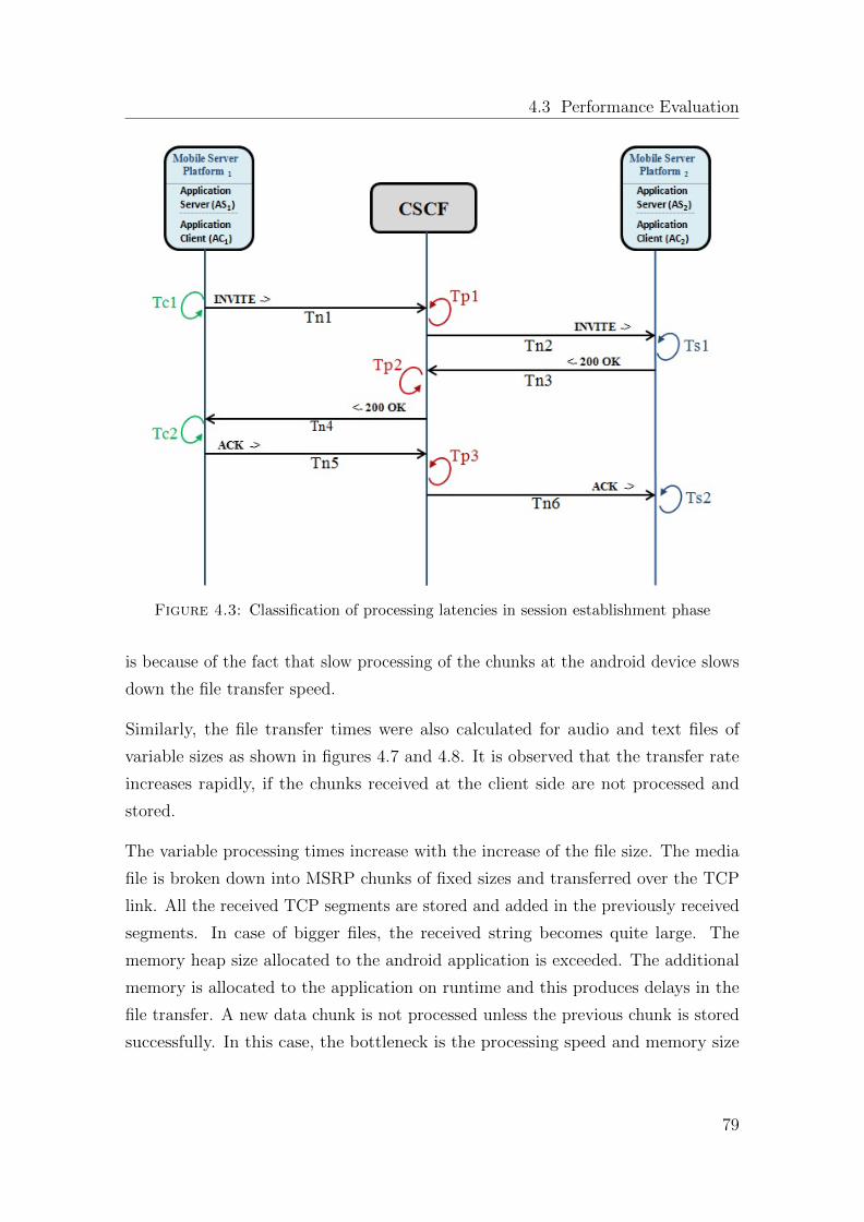
4.3 Performance Evaluation
Figure 4.3: Classification of processing latencies in session establishment phase
is because of the fact that slow processing of the chunks at the android device slows
down the file transfer speed.
Similarly, the file transfer times were also calculated for audio and text files of
variable sizes as shown in figures 4.7 and 4.8. It is observed that the transfer rate
increases rapidly, if the chunks received at the client side are not processed and
stored.
The variable processing times increase with the increase of the file size. The media
file is broken down into MSRP chunks of fixed sizes and transferred over the TCP
link. All the received TCP segments are stored and added in the previously received
segments. In case of bigger files, the received string becomes quite large. The
memory heap size allocated to the android application is exceeded. The additional
memory is allocated to the application on runtime and this produces delays in the
file transfer. A new data chunk is not processed unless the previous chunk is stored
successfully. In this case, the bottleneck is the processing speed and memory size
79
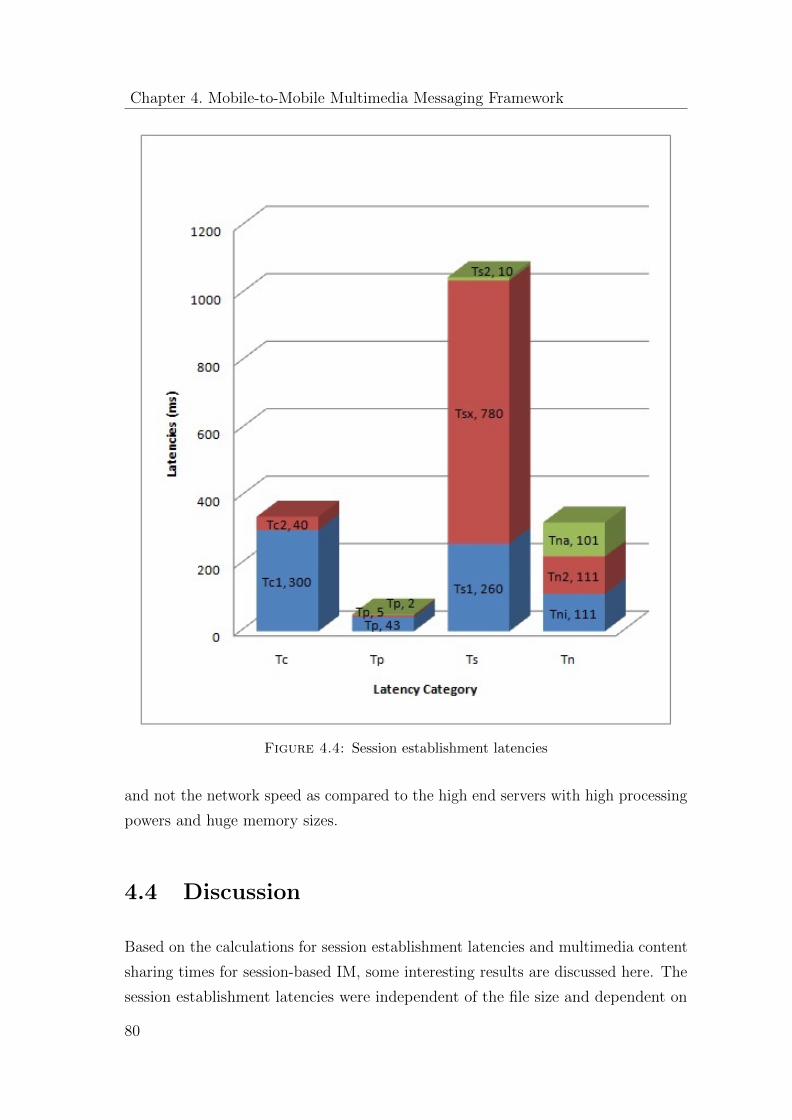
Chapter 4. Mobile-to-Mobile Multimedia Messaging Framework
Figure 4.4: Session establishment latencies
and not the network speed as compared to the high end servers with high processing
powers and huge memory sizes.
4.4 Discussion
Based on the calculations for session establishment latencies and multimedia content
sharing times for session-based IM, some interesting results are discussed here. The
session establishment latencies were independent of the file size and dependent on
80
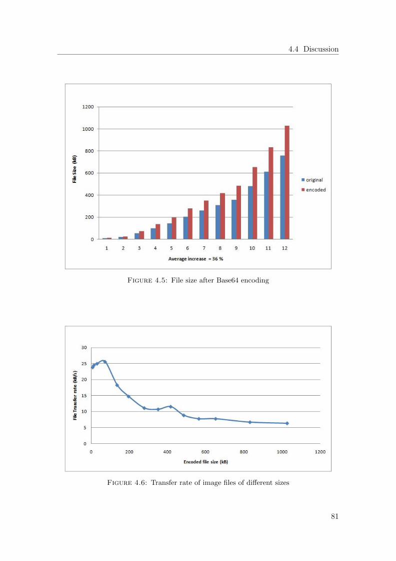
4.4 Discussion
Figure 4.5: File size after Base64 encoding
Figure 4.6: Transfer rate of image files of different sizes
81
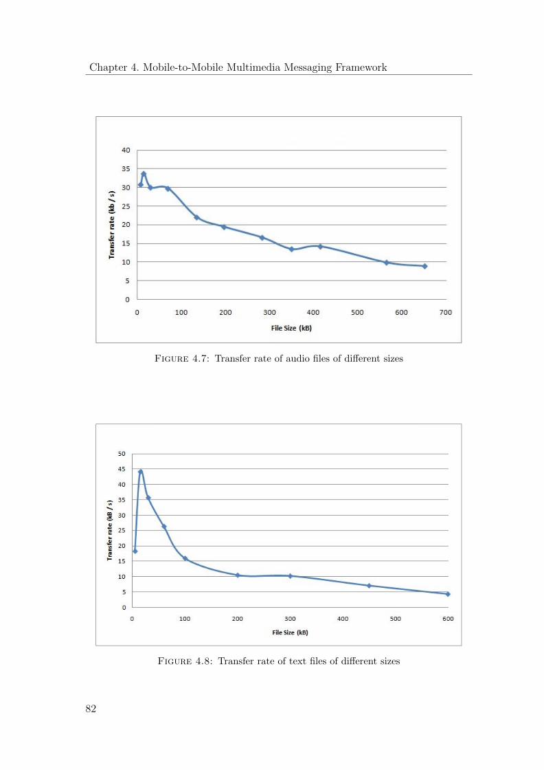
Chapter 4. Mobile-to-Mobile Multimedia Messaging Framework
Figure 4.7: Transfer rate of audio files of different sizes
Figure 4.8: Transfer rate of text files of different sizes
82
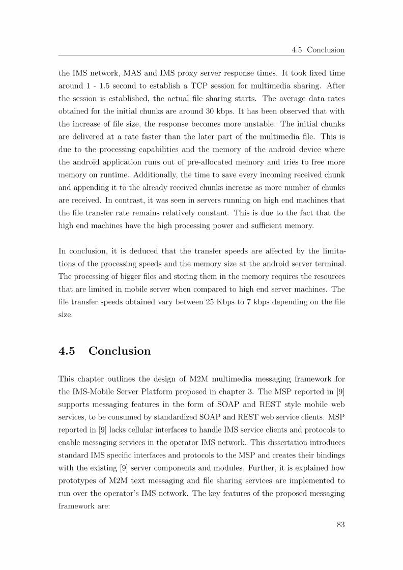
4.5 Conclusion
the IMS network, MAS and IMS proxy server response times. It took fixed time
around 1 - 1.5 second to establish a TCP session for multimedia sharing. After
the session is established, the actual file sharing starts. The average data rates
obtained for the initial chunks are around 30 kbps. It has been observed that with
the increase of file size, the response becomes more unstable. The initial chunks
are delivered at a rate faster than the later part of the multimedia file. This is
due to the processing capabilities and the memory of the android device where
the android application runs out of pre-allocated memory and tries to free more
memory on runtime. Additionally, the time to save every incoming received chunk
and appending it to the already received chunks increase as more number of chunks
are received. In contrast, it was seen in servers running on high end machines that
the file transfer rate remains relatively constant. This is due to the fact that the
high end machines have the high processing power and sufficient memory.
In conclusion, it is deduced that the transfer speeds are affected by the limita-
tions of the processing speeds and the memory size at the android server terminal.
The processing of bigger files and storing them in the memory requires the resources
that are limited in mobile server when compared to high end server machines. The
file transfer speeds obtained vary between 25 Kbps to 7 kbps depending on the file
size.
4.5 Conclusion
This chapter outlines the design of M2M multimedia messaging framework for
the IMS-Mobile Server Platform proposed in chapter 3. The MSP reported in [9]
supports messaging features in the form of SOAP and REST style mobile web
services, to be consumed by standardized SOAP and REST web service clients. MSP
reported in [9] lacks cellular interfaces to handle IMS service clients and protocols to
enable messaging services in the operator IMS network. This dissertation introduces
standard IMS specific interfaces and protocols to the MSP and creates their bindings
with the existing [9] server components and modules. Further, it is explained how
prototypes of M2M text messaging and file sharing services are implemented to
run over the operator’s IMS network. The key features of the proposed messaging
framework are:
83
Chapter 4. Mobile-to-Mobile Multimedia Messaging Framework
� The text messaging service is realized in a request-response fashion together
with the mapping of SIP MESSAGE mechanism over REST-synchronous
architecture of the Mobile Server Platform.
� The file sharing service is realized in a session-oriented fashion together with
the mapping of SIP INVITE mechanism over REST-asynchronous architecture
of the Mobile Server Platform.
� The MSRP protocol is implemented to support session-oriented multimedia
transfers in the IMS network.
The performance aspects of transport protocol and file transmissions are evaluated.
It is noticed that the session establishment latency is independent of the file size and
dependent on the underlying IMS network performance. The file transfer latency is
dependent on the network speed and processing power of the mobile devices. The
network speed is perceived to be stable and, therefore, the bottleneck to achieve
good transfer rate is the processing capability of the mobile devices.
84
Chapter 5
Mobile-to-Mobile Multimedia
Streaming Framework
This chapter presents the design and implementation of M2M multimedia streaming
framework of the MSP. The implementation supports the standardized protocols
and interfaces of the IMS network. The proposed framework is aimed to conform to
the functional and non-functional implementation requirements for the RTP based
audio and video streaming applications addressed by the 3GPP telecom association.
These requirements are summarized in section 5.1. The chapter describes how M2M
multimedia messaging streaming is realized in a service oriented fashion. Furthermore,
the chapter provides the performance evaluation of the newly implemented streaming
service prototype. The work presented in this chapter is mainly based on the author
contribution in [22, 31]. Moreover, a master thesis guided by the author [13] has
elaborated implementation details and conducted some additional measurements on
the topic.
5.1 Multimedia Streaming Requirements in IM-
S/LTE network
3GPP specification TS 26.411 [4] for multimedia streaming applications define
implementation requirements for RTP based audio and video application for an IMS
client. Moreover, the 3GPP have provided a set of standardized requirements for
85
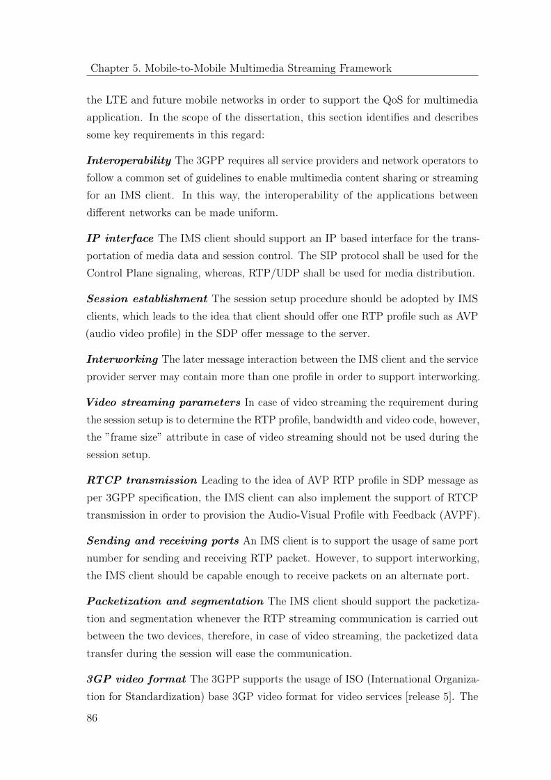
Chapter 5. Mobile-to-Mobile Multimedia Streaming Framework
the LTE and future mobile networks in order to support the QoS for multimedia
application. In the scope of the dissertation, this section identifies and describes
some key requirements in this regard:
Interoperability The 3GPP requires all service providers and network operators to
follow a common set of guidelines to enable multimedia content sharing or streaming
for an IMS client. In this way, the interoperability of the applications between
different networks can be made uniform.
IP interface The IMS client should support an IP based interface for the trans-
portation of media data and session control. The SIP protocol shall be used for the
Control Plane signaling, whereas, RTP/UDP shall be used for media distribution.
Session establishment The session setup procedure should be adopted by IMS
clients, which leads to the idea that client should offer one RTP profile such as AVP
(audio video profile) in the SDP offer message to the server.
Interworking The later message interaction between the IMS client and the service
provider server may contain more than one profile in order to support interworking.
Video streaming parameters In case of video streaming the requirement during
the session setup is to determine the RTP profile, bandwidth and video code, however,
the ”frame size” attribute in case of video streaming should not be used during the
session setup.
RTCP transmission Leading to the idea of AVP RTP profile in SDP message as
per 3GPP specification, the IMS client can also implement the support of RTCP
transmission in order to provision the Audio-Visual Profile with Feedback (AVPF).
Sending and receiving ports An IMS client is to support the usage of same port
number for sending and receiving RTP packet. However, to support interworking,
the IMS client should be capable enough to receive packets on an alternate port.
Packetization and segmentation The IMS client should support the packetiza-
tion and segmentation whenever the RTP streaming communication is carried out
between the two devices, therefore, in case of video streaming, the packetized data
transfer during the session will ease the communication.
3GP video format The 3GPP supports the usage of ISO (International Organiza-
tion for Standardization) base 3GP video format for video services [release 5]. The
86
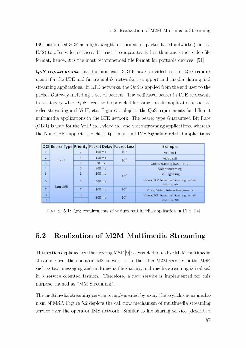
5.2 Realization of M2M Multimedia Streaming
ISO introduced 3GP as a light weight file format for packet based networks (such as
IMS) to offer video services. It’s size is comparatively less than any other video file
format, hence, it is the most recommended file format for portable devices. [51]
QoS requirements Last but not least, 3GPP have provided a set of QoS require-
ments for the LTE and future mobile networks to support multimedia sharing and
streaming applications. In LTE networks, the QoS is applied from the end user to the
packet Gateway including a set of bearers. The dedicated bearer in LTE represents
to a category where QoS needs to be provided for some specific applications, such as
video streaming and VoIP, etc. Figure 5.1 depicts the QoS requirements for different
multimedia applications in the LTE network. The bearer type Guaranteed Bit Rate
(GBR) is used for the VoIP call, video call and video streaming applications, whereas,
the Non-GBR supports the chat, ftp, email and IMS Signaling related applications.
Figure 5.1: QoS requirements of variuos mutlimedia application in LTE [24]
5.2 Realization of M2M Multimedia Streaming
This section explains how the existing MSP [9] is extended to realize M2M multimedia
streaming over the operator IMS network. Like the other M2M services in the MSP,
such as text messaging and multimedia file sharing, multimedia streaming is realized
in a service oriented fashion. Therefore, a new service is implemented for this
purpose, named as ”MM Streaming”.
The multimedia streaming service is implemented by using the asynchronous mecha-
nism of MSP. Figure 5.2 depicts the call flow mechanism of multimedia streaming
service over the operator IMS network. Similar to file sharing service (described
87
Chapter 5. Mobile-to-Mobile Multimedia Streaming Framework
in section 4.2.2), a SIP INVITE request from one MSP is sent to another MSP in
order to create a multimedia session between two parties. The actual media transfer
starts after the completion of session negotiations. In contrast to MSRP protocol in
file sharing service, the multimedia streaming is achieved with 3GPP recommended
RTP and RTSP protocols. The following section enfolds the message flow details of
session establishment and media delivery phase.
Figure 5.2: Call flow of M2M mutlimedia streaming service
5.3 Session Establishment Phase
SIP and SDP are the main protocols which are used for session negotiations in
multimedia streaming service. In general, the steps involved in session negotiations
for multimedia streaming service are exactly the same as described for file sharing
service in section 4.2.2. However, the messaging constructs and attributes involved
88
5.3 Session Establishment Phase
in SDP Offer-Answer model of multimedia streaming service are quite different from
the file sharing service.
Listing 5.1 shows a sample SIP INVITE request which is sent from a user Bob to
Alice in order to access the ”MM Streaming” service. Here the SDP message content
is as follows:
v - indicates the SDP version v=0
o - lists the organization of the calling party and the IP version is 4 with actual IP
address 192.168.2.101
s - describes the SDP message as IMS Call
c - 192.168.2.101 is the IP address of the originator
m - describes the media type as RTP/AVP expected by the Bob. The port number
(6022) is where Bob wants to receive the audio.
a - gives the media attributes PCMU, PCMA and telephone-event which are mapped
with number 0, 8 and 11
The SDP message basically contains two type of information: session information
and media information. In the SIP INVITE request, the lines starting with v,o,s,p,c,t
indicate the session information i.e., version and user identifiers (v= and o= lines),
subject of the session (s= line), phone number to obtain the information about the
session (p = line), Bob’s IP address (c= line) and time of the session (t = line).
Whereas, the lines starting with m and a indicate media information i.e., media
specific information (m = lines) and further information about the media (a = lines).
The lines ”a=curr : qos” and ”a=des : qos” are related with QoS information that
will be discussed later in section 6.1.3.
Once the SIP INVITE request is reached to the Alice’s MobAS, a ”100 Trying”
message (listing 5.2) is sent back as an acknowledgment. Then Alice’s MobAS reads
the SDP content for the requested service name and the corresponding session and
media related attributes. If everything is available and agreed, it sends a ”180
Ringing” message (listing 5.3) back towards Bob to inform that the called side is
being rung. Then Alice’s MobAC answers the ringing with a ”200 OK” (listing
5.4) message and wait for an acknowledgment (ACK message) from Bob. Once
89
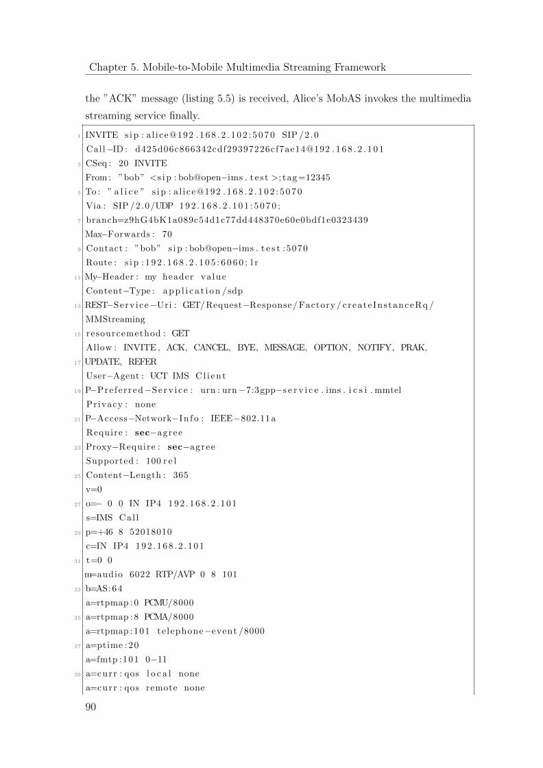
Chapter 5. Mobile-to-Mobile Multimedia Streaming Framework
the ”ACK” message (listing 5.5) is received, Alice’s MobAS invokes the multimedia
streaming service finally.
1 INVITE s i p : a l i ce@192 . 1 6 8 . 2 . 1 0 2 : 5 0 7 0 SIP /2 .0
Cal l−ID : d425d06c866342cdf29397226cf7ae14@192 . 1 6 8 . 2 . 1 0 1
3 CSeq : 20 INVITE
From : ”bob” <s i p : bob@open−ims . t e s t >; tag =12345
5 To : ” a l i c e ” s i p : a l i ce@192 . 1 6 8 . 2 . 1 0 2 : 5 0 7 0
Via : SIP /2 .0/UDP 1 9 2 . 1 6 8 . 2 . 1 0 1 : 5 0 7 0 ;
7 branch=z9hG4bK1a089c54d1c77dd448370e60e0bdf1e0323439
Max−Forwards : 70
9 Contact : ”bob” s i p : bob@open−ims . t e s t :5070
Route : s i p : 1 9 2 . 1 6 8 . 2 . 1 0 5 : 6 0 6 0 ; l r
11 My−Header : my header va lue
Content−Type : a p p l i c a t i o n /sdp
13 REST−Serv ice−Uri : GET/Request−Response/ Factory / create InstanceRq /
MMStreaming
15 resourcemethod : GET
Allow : INVITE , ACK, CANCEL, BYE, MESSAGE, OPTION, NOTIFY, PRAK,
17 UPDATE, REFER
User−Agent : UCT IMS Cl i en t
19 P−Pre fe r red−S e r v i c e : urn : urn−7:3gpp−s e r v i c e . ims . i c s i . mmtel
Privacy : none
21 P−Access−Network−In f o : IEEE−802.11a
Require : sec−agree
23 Proxy−Require : sec−agree
Supported : 100 r e l
25 Content−Length : 365
v=0
27 o=− 0 0 IN IP4 1 9 2 . 1 6 8 . 2 . 1 0 1
s=IMS Cal l
29 p=+46 8 52018010
c=IN IP4 1 9 2 . 1 6 8 . 2 . 1 0 1
31 t=0 0
m=audio 6022 RTP/AVP 0 8 101
33 b=AS:64
a=rtpmap : 0 PCMU/8000
35 a=rtpmap : 8 PCMA/8000
a=rtpmap :101 te lephone−event /8000
37 a=ptime :20
a=fmtp :101 0−11
39 a=curr : qos l o c a l none
a=curr : qos remote none
90
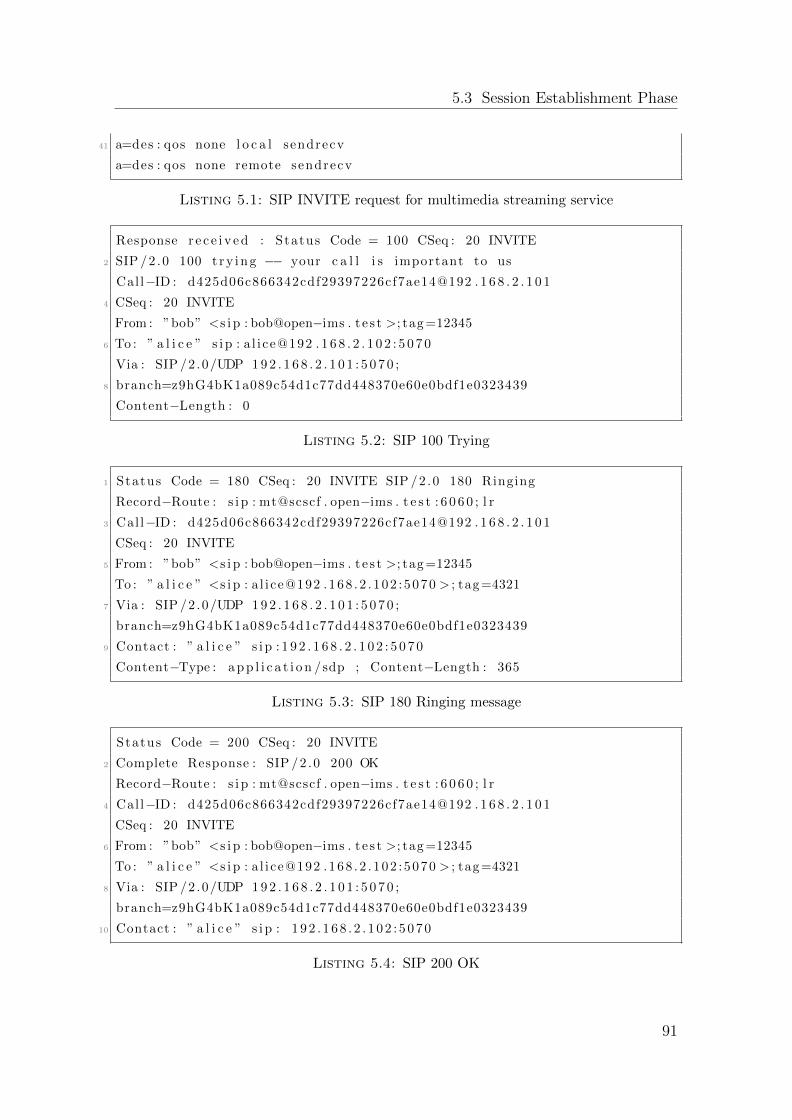
5.3 Session Establishment Phase
41 a=des : qos none l o c a l sendrecv
a=des : qos none remote sendrecv
Listing 5.1: SIP INVITE request for multimedia streaming service
Response r e c e i v e d : Status Code = 100 CSeq : 20 INVITE
2 SIP /2 .0 100 t ry ing −− your c a l l i s important to us
Cal l−ID : d425d06c866342cdf29397226cf7ae14@192 . 1 6 8 . 2 . 1 0 1
4 CSeq : 20 INVITE
From : ”bob” <s i p : bob@open−ims . t e s t >; tag =12345
6 To : ” a l i c e ” s i p : a l i ce@192 . 1 6 8 . 2 . 1 0 2 : 5 0 7 0
Via : SIP /2 .0/UDP 1 9 2 . 1 6 8 . 2 . 1 0 1 : 5 0 7 0 ;
8 branch=z9hG4bK1a089c54d1c77dd448370e60e0bdf1e0323439
Content−Length : 0
Listing 5.2: SIP 100 Trying
1 Status Code = 180 CSeq : 20 INVITE SIP /2 .0 180 Ringing
Record−Route : s i p : mt@scscf . open−ims . t e s t : 6 0 6 0 ; l r
3 Call−ID : d425d06c866342cdf29397226cf7ae14@192 . 1 6 8 . 2 . 1 0 1
CSeq : 20 INVITE
5 From : ”bob” <s i p : bob@open−ims . t e s t >; tag =12345
To : ” a l i c e ” <s i p : a l i ce@192 .168 . 2 . 102 : 5070 > ; tag =4321
7 Via : SIP /2 .0/UDP 1 9 2 . 1 6 8 . 2 . 1 0 1 : 5 0 7 0 ;
branch=z9hG4bK1a089c54d1c77dd448370e60e0bdf1e0323439
9 Contact : ” a l i c e ” s i p : 1 9 2 . 1 6 8 . 2 . 1 0 2 : 5 0 7 0
Content−Type : a p p l i c a t i o n /sdp ; Content−Length : 365
Listing 5.3: SIP 180 Ringing message
Status Code = 200 CSeq : 20 INVITE
2 Complete Response : SIP /2 .0 200 OK
Record−Route : s i p : mt@scscf . open−ims . t e s t : 6 0 6 0 ; l r
4 Call−ID : d425d06c866342cdf29397226cf7ae14@192 . 1 6 8 . 2 . 1 0 1
CSeq : 20 INVITE
6 From : ”bob” <s i p : bob@open−ims . t e s t >; tag =12345
To : ” a l i c e ” <s i p : a l i ce@192 .168 . 2 . 102 : 5070 > ; tag =4321
8 Via : SIP /2 .0/UDP 1 9 2 . 1 6 8 . 2 . 1 0 1 : 5 0 7 0 ;
branch=z9hG4bK1a089c54d1c77dd448370e60e0bdf1e0323439
10 Contact : ” a l i c e ” s i p : 1 9 2 . 1 6 8 . 2 . 1 0 2 : 5 0 7 0
Listing 5.4: SIP 200 OK
91
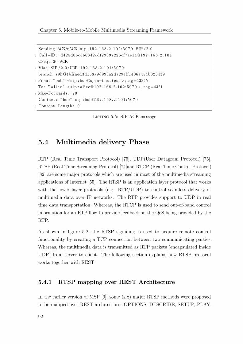
Chapter 5. Mobile-to-Mobile Multimedia Streaming Framework
Sending ACK/nACK s i p : 1 9 2 . 1 6 8 . 2 . 1 0 2 : 5 0 7 0 SIP /2 .0
2 Call−ID : d425d06c866342cdf29397226cf7ae14@192 . 1 6 8 . 2 . 1 0 1
CSeq : 20 ACK
4 Via : SIP /2 .0/UDP 1 9 2 . 1 6 8 . 2 . 1 0 1 : 5 0 7 0 ;
branch=z9hG4bKaed3d158a9d993a2d729eff1406a454b323439
6 From : ”bob” <s i p : bob@open−ims . t e s t >; tag =12345
To : ” a l i c e ” <s i p : a l i ce@192 .168 . 2 . 102 : 5070 > ; tag =4321
8 Max−Forwards : 70
Contact : ”bob” s i p : bob@192 . 1 6 8 . 2 . 1 0 1 : 5 0 7 0
10 Content−Length : 0
Listing 5.5: SIP ACK message
5.4 Multimedia delivery Phase
RTP (Real Time Transport Protocol) [75], UDP(User Datagram Protocol) [75],
RTSP (Real Time Streaming Protocol) [74]and RTCP (Real Time Control Protocol)
[82] are some major protocols which are used in most of the multimedia streaming
applications of Internet [55]. The RTSP is an application layer protocol that works
with the lower layer protocols (e.g. RTP/UDP) to control seamless delivery of
multimedia data over IP networks. The RTP provides support to UDP in real
time data transportation. Whereas, the RTCP is used to send out-of-band control
information for an RTP flow to provide feedback on the QoS being provided by the
RTP.
As shown in figure 5.2, the RTSP signaling is used to acquire remote control
functionality by creating a TCP connection between two communicating parties.
Whereas, the multimedia data is transmitted as RTP packets (encapsulated inside
UDP) from server to client. The following section explains how RTSP protocol
works together with REST
5.4.1 RTSP mapping over REST Architecture
In the earlier version of MSP [9], some (six) major RTSP methods were proposed
to be mapped over REST architecture: OPTIONS, DESCRIBE, SETUP, PLAY,
92
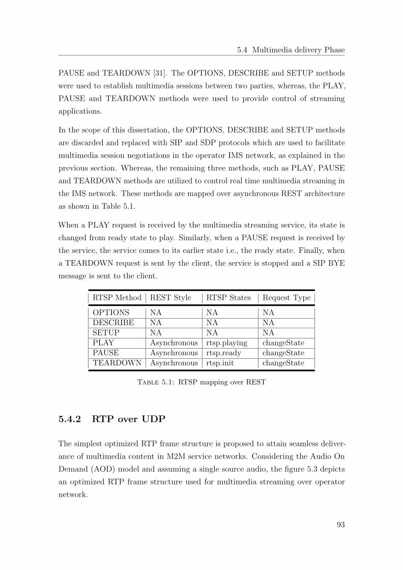
5.4 Multimedia delivery Phase
PAUSE and TEARDOWN [31]. The OPTIONS, DESCRIBE and SETUP methods
were used to establish multimedia sessions between two parties, whereas, the PLAY,
PAUSE and TEARDOWN methods were used to provide control of streaming
applications.
In the scope of this dissertation, the OPTIONS, DESCRIBE and SETUP methods
are discarded and replaced with SIP and SDP protocols which are used to facilitate
multimedia session negotiations in the operator IMS network, as explained in the
previous section. Whereas, the remaining three methods, such as PLAY, PAUSE
and TEARDOWN methods are utilized to control real time multimedia streaming in
the IMS network. These methods are mapped over asynchronous REST architecture
as shown in Table 5.1.
When a PLAY request is received by the multimedia streaming service, its state is
changed from ready state to play. Similarly, when a PAUSE request is received by
the service, the service comes to its earlier state i.e., the ready state. Finally, when
a TEARDOWN request is sent by the client, the service is stopped and a SIP BYE
message is sent to the client.
RTSP Method REST Style RTSP States Request Type
OPTIONS NA NA NADESCRIBE NA NA NASETUP NA NA NAPLAY Asynchronous rtsp.playing changeStatePAUSE Asynchronous rtsp.ready changeStateTEARDOWN Asynchronous rtsp.init changeState
Table 5.1: RTSP mapping over REST
5.4.2 RTP over UDP
The simplest optimized RTP frame structure is proposed to attain seamless deliver-
ance of multimedia content in M2M service networks. Considering the Audio On
Demand (AOD) model and assuming a single source audio, the figure 5.3 depicts
an optimized RTP frame structure used for multimedia streaming over operator
network.
93
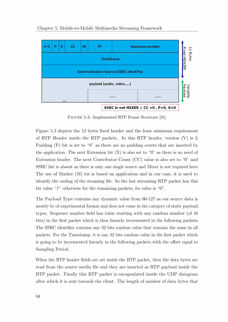
Chapter 5. Mobile-to-Mobile Multimedia Streaming Framework
Figure 5.3: Implemented RTP Frame Structure [31]
Figure 5.3 depicts the 12 bytes fixed header and the least minimum requirement
of RTP Header inside the RTP packets. In this RTP header, version (V) is 2.
Padding (P) bit is set to “0” as there are no padding octets that are inserted by
the application. The next Extension bit (X) is also set to “0” as there is no need of
Extension header. The next Contributor Count (CC) value is also set to “0” and
SSRC list is absent as there is only one single source and Mixer is not required here.
The use of Marker (M) bit is based on application and in our case, it is used to
identify the ending of the steaming file. So the last streaming RTP packet has this
bit value “1” otherwise for the remaining packets, its value is “0”.
The Payload Type contains any dynamic value from 96-127 as our source data is
mostly be of experimental format and does not come in the category of static payload
types. Sequence number field has value starting with any random number (of 16
bits) in the first packet which is then linearly incremented in the following packets.
The SSRC identifier contains any 32 bits random value that remains the same in all
packets. For the Timestamp, it is any 32 bits random value in the first packet which
is going to be incremented linearly in the following packets with the offset equal to
Sampling Period.
When the RTP header fields are set inside the RTP packet, then the data bytes are
read from the source media file and they are inserted as RTP payload inside the
RTP packet. Finally this RTP packet is encapsulated inside the UDP datagram
after which it is sent towards the client. The length of number of data bytes that
94
5.5 Performance Evaluation
can be inserted as RTP payload inside the RTP packet depends upon the Maximum
Transmission Unit (MTU) allowed on the network path between the server and the
client. For example, if the MTU is of 1500 bytes, then the maximum RTP payload
size is 1500 - (20 + 12 + 8) = 1460 bytes.
5.5 Performance Evaluation
A prototype application was implemented in order to evaluate the performance of the
newly created multimedia streaming service. The application allows the two network
users to create an audio/video streaming session between them. As a usecase, a
user Alice requests another user Bob to start a video streaming session. Here, the
Service Creation Time (SCT) represents the time utilized in the construction of the
requested service at Bob’s MSP. This is a time between receiving the initial INVITE
request and sending a 200 Ok response back. Whereas, the Service Invocation Time
(SIT) represents the time required by the MSP to bring the demanded service in a
ready state. This is a time taken by Bob’s MSP between sending a 200 Ok response
and starting a service thread after receiving an ACK from Alice.
Once the session is created, Bob sends a video URL to Alice over a TCP connection.
This time is recorded as URL Receive Time (URT). After receiving the video
URL, Alice’s MSP starts a streaming connection (UDP) with the target server.
Consequently, the Android VideoView API starts playing the video on the Alice’s
device. Here, the Video Streaming Time (VST) is calculated from starting the video
at Alice’s device till its end.
For evaluation purposes, the latencies such as SCT, SIT and URT are categorized
as session establishment latencies. Whereas, VST will be represented as multimedia
streaming latency.
5.5.1 Testbed
Performance evaluation by measure in the proposed framework has been extensively
carried out in order to study the processing latencies during the session establishment
and multimedia streaming phase. The testbed environment consists of two mobile
95
Chapter 5. Mobile-to-Mobile Multimedia Streaming Framework
user terminals and one server machine. The configuration of the testbed is as follows:
User Terminal - 1 with MSP:
Model: HTC Legend
Platform: Android 2.2
Camera: 5-megapixel color camera with auto focus and flash
Memory: ROM: 512MB RAM: 384MB
CPU Speed: 600MHz
User Terminal -2 with MSP:
Model: Samsung Galaxy S3 (i900)
Platform: Android 4.1.2 (Jelly Bean)
Camera: b-megapixel color camera with auto focus
Memory: ROM: 16 GB RAM: 1 GB
CPU Speed: Quad-core 1.4 GHz
Server Machine with IMS Testbed:
The Fraunhofer FOKUS OpenIMS Core is used as an IMS testbed. It comes as an
Eclipse plug-in. It was running on the machine with the following specifications.
System Manufacturer: IBM
Model: Lenovo T41
Processor: Intel 1.7 GHz
Memory: RAM: 1 GB
Operating System: Linux Ubuntu 12.04
IDE: Eclipse JUNO
Network Configurations
ADSL: G.992.5 (ADSL2+)
Download: 17034 Kbps
Upload: 1149 Kbps
No of clients: 5
96
5.5 Performance Evaluation
Video Sources:
Two video files were selected for the evaluation purpose:
Video 1:
Source: http://m.youtube.com/watch?client=mv-google
Length of video: 1:00 min
Name of video: Android in Space
Video 2:
Source: http://www.youtube.com/watch?v=QHIzzQB4Lew
Length of video: 0:45 second
Name of video: New Skype for Android
5.5.2 Session Establishment Latencies
Figures 5.4 and 5.5 depict the session establishment latencies of Video-1 and Video-2
files respectively. It is worthy to mention that the mean SCT value in Video-1 case
is exactly the same to the corresponding mean SCT value in Video-2 case. Similar
is the case of SIT i.e., the mean SIT value in Video-1 case is exactly the same to the
corresponding mean SIT value in Video-2 case. The reasoning of same aggregated
SCT and SIT values of both videos are because of the same processing time taken
to complete service creation. So, for any video file of length (l), the SIT and SCT
values will be constant depending on the processing speed of the device’s processor.
Here, one can notice that the given values of SCT and SIT are not exactly the same
in figures. However, as the time measurements are taken in milliseconds, so this
small difference is negligible.
On the contrary, the mean URT value in Video-1 case is smaller than that of the
Video-2. However, this behavior of URT is unpredictable because its computation is
strictly dependent on the network delay. If the network is good (small delay), the
URL will be received in a short time. But, if the network is bad (big delays), the
URL receive time will be bigger.
97
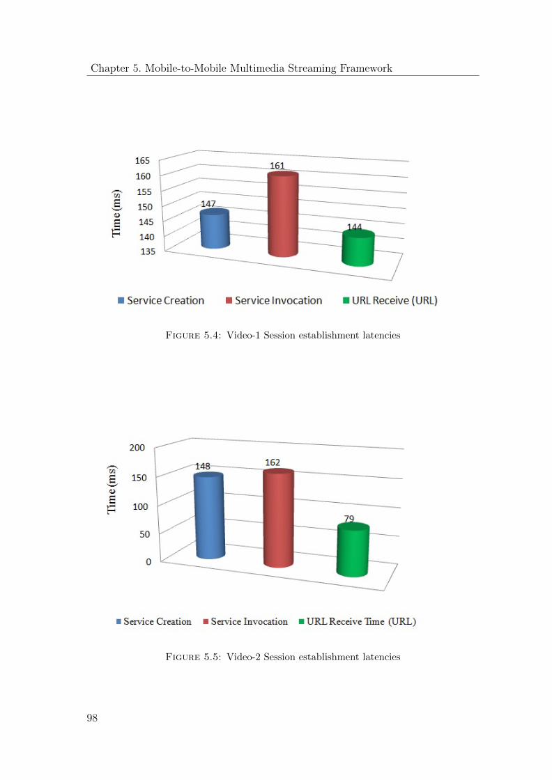
Chapter 5. Mobile-to-Mobile Multimedia Streaming Framework
Figure 5.4: Video-1 Session establishment latencies
Figure 5.5: Video-2 Session establishment latencies
98
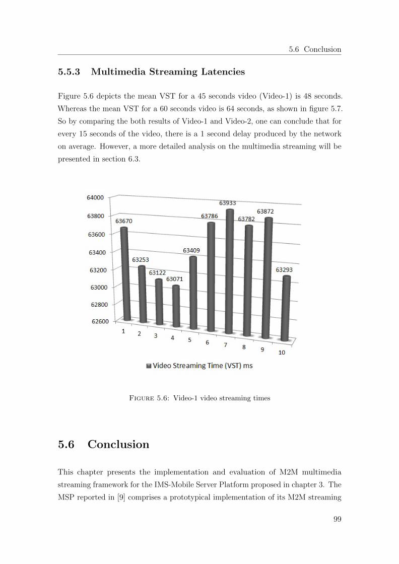
5.6 Conclusion
5.5.3 Multimedia Streaming Latencies
Figure 5.6 depicts the mean VST for a 45 seconds video (Video-1) is 48 seconds.
Whereas the mean VST for a 60 seconds video is 64 seconds, as shown in figure 5.7.
So by comparing the both results of Video-1 and Video-2, one can conclude that for
every 15 seconds of the video, there is a 1 second delay produced by the network
on average. However, a more detailed analysis on the multimedia streaming will be
presented in section 6.3.
Figure 5.6: Video-1 video streaming times
5.6 Conclusion
This chapter presents the implementation and evaluation of M2M multimedia
streaming framework for the IMS-Mobile Server Platform proposed in chapter 3. The
MSP reported in [9] comprises a prototypical implementation of its M2M streaming
99

Chapter 5. Mobile-to-Mobile Multimedia Streaming Framework
Figure 5.7: Video-2 video streaming times
framework that is limited to support standardized SOAP and REST interfaced service
clients. Chapter 5 introduces the implementation of 3GPP standard conformant
interfaces and protocols to realize M2M streaming over an operator IMS network. A
prototype video streaming application is developed and tested as a proof of concept.
The key features of the proposed multimedia streaming framework are:
� The multimedia streaming is realized in a session-oriented fashion together with
the mapping of SIP INVITE mechanism over REST-asynchronous architecture
of the Mobile Server Platform.
� RTSP protocol signaling is applied in order to achieve the remote control
functionality in the multimedia applications, such as stopping, pausing and
resuming the running media.
� A light version of RTP protocol is applied for multimedia transmission using
UDP.
100
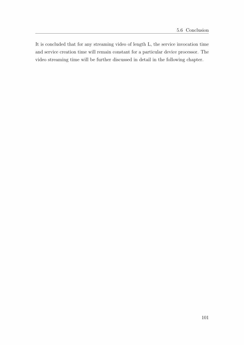
5.6 Conclusion
It is concluded that for any streaming video of length L, the service invocation time
and service creation time will remain constant for a particular device processor. The
video streaming time will be further discussed in detail in the following chapter.
101

Chapter 6
Mobile-to-Mobile Quality of
Service Framework
The cellular world has witnessed a striking increase in mobile broadband subscribers
and their traffic volume per subscriber. An obvious reason to this trend is the
attractive data tariffs by operators e.g., flat-rate package and, on the other hand, the
introduction of more advanced smart phone applications in the market. However,
from the network perspective, provisioning high profile multimedia applications over
the bandwidth-constrained cellular networks is not simply straight forward. QoS
has always been an issue in this regard. Therefore, mobile operators have to employ
more sophisticated control and policy enforcement mechanism in order to ensure
the quality of individual services running over their network. More precisely, they
require a precise way to do service differentiation and apply QoS policies accordingly.
This chapter presents the QoS framework of the MSP. The chapter enfolds how
the proposed QoS framework operates in user registration, session establishment
and multimedia delivery phase to provide an end-to-end QoS control for an existing
multimedia streaming service. A promising feature of the proposed QoS framework
is to allow the cellular operators to employ QoS control based on the user profiles
classification. Hence, a systematic approach is adopted to study the behavior of
a video streaming prototype based on different network settings and various user
profiles.
103
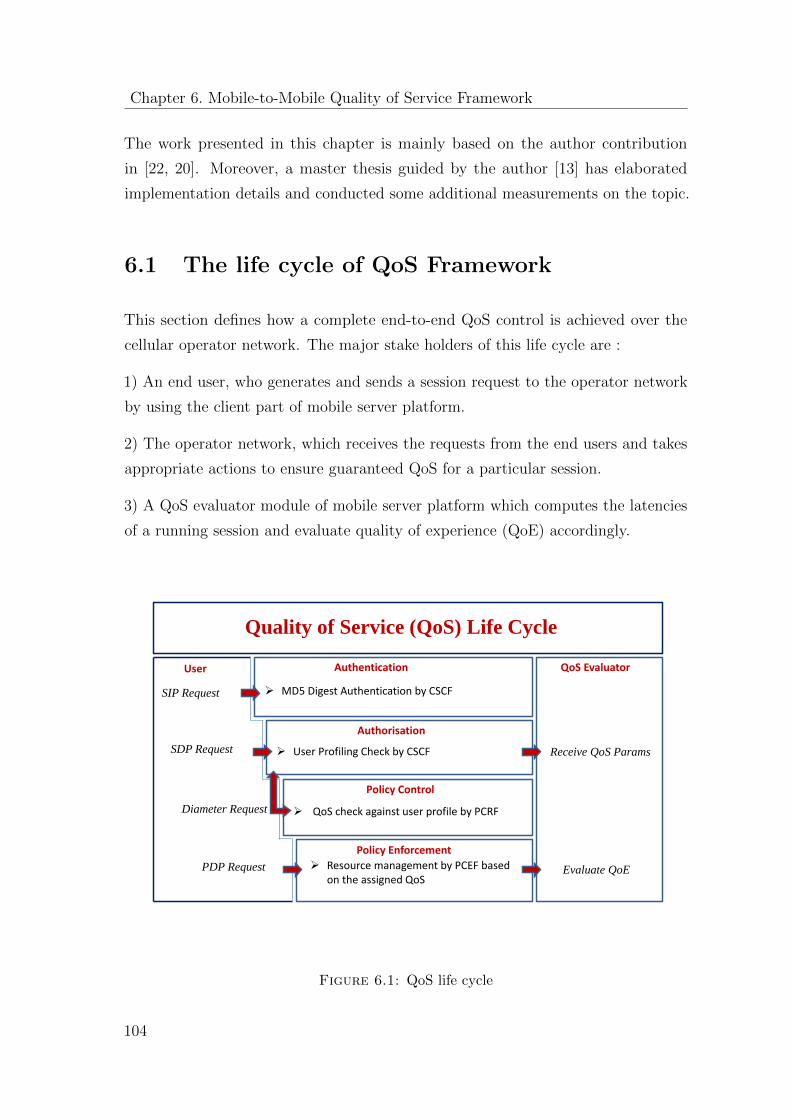
Chapter 6. Mobile-to-Mobile Quality of Service Framework
The work presented in this chapter is mainly based on the author contribution
in [22, 20]. Moreover, a master thesis guided by the author [13] has elaborated
implementation details and conducted some additional measurements on the topic.
6.1 The life cycle of QoS Framework
This section defines how a complete end-to-end QoS control is achieved over the
cellular operator network. The major stake holders of this life cycle are :
1) An end user, who generates and sends a session request to the operator network
by using the client part of mobile server platform.
2) The operator network, which receives the requests from the end users and takes
appropriate actions to ensure guaranteed QoS for a particular session.
3) A QoS evaluator module of mobile server platform which computes the latencies
of a running session and evaluate quality of experience (QoE) accordingly.
Quality of Service (QoS) Life Cycle
QoS EvaluatorAuthentication
MD5 Digest Authentication by CSCF
Authorisation
User Profiling Check by CSCF
Policy Control
QoS check against user profile by PCRF
Policy Enforcement
Resource management by PCEF based on the assigned QoS
User
SIP Request
SDP Request
Diameter Request
PDP Request
Receive QoS Params
Evaluate QoE
Figure 6.1: QoS life cycle
104
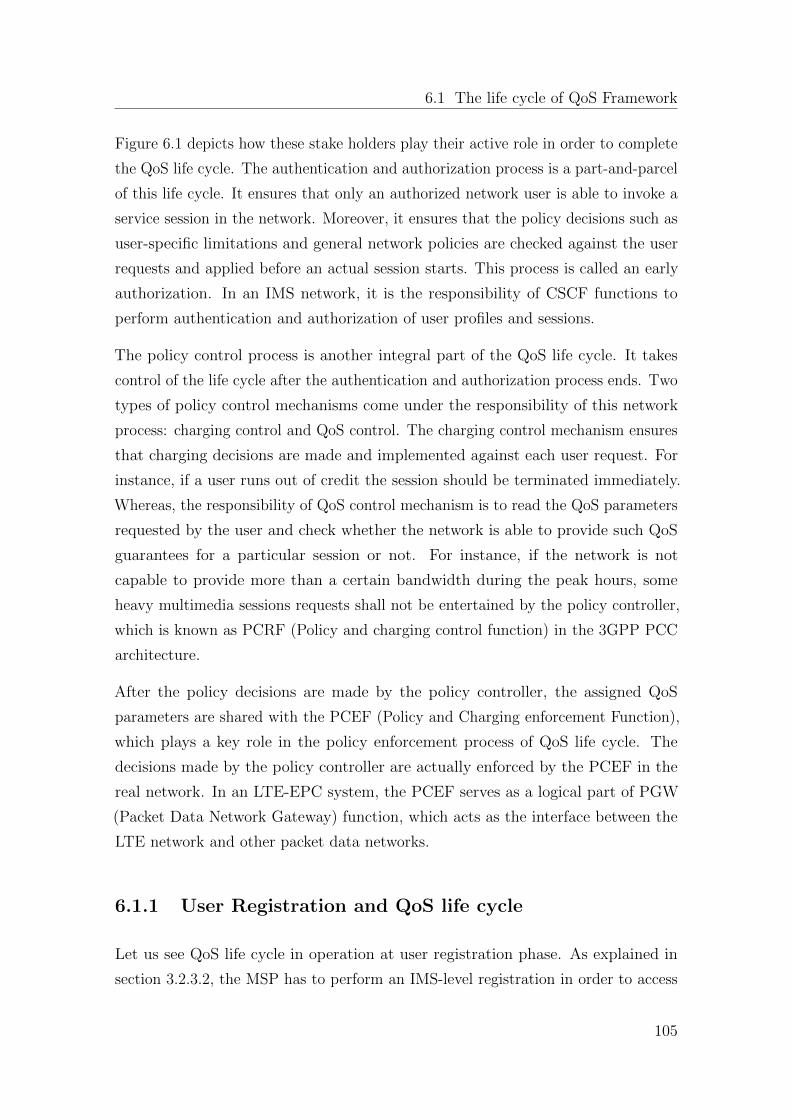
6.1 The life cycle of QoS Framework
Figure 6.1 depicts how these stake holders play their active role in order to complete
the QoS life cycle. The authentication and authorization process is a part-and-parcel
of this life cycle. It ensures that only an authorized network user is able to invoke a
service session in the network. Moreover, it ensures that the policy decisions such as
user-specific limitations and general network policies are checked against the user
requests and applied before an actual session starts. This process is called an early
authorization. In an IMS network, it is the responsibility of CSCF functions to
perform authentication and authorization of user profiles and sessions.
The policy control process is another integral part of the QoS life cycle. It takes
control of the life cycle after the authentication and authorization process ends. Two
types of policy control mechanisms come under the responsibility of this network
process: charging control and QoS control. The charging control mechanism ensures
that charging decisions are made and implemented against each user request. For
instance, if a user runs out of credit the session should be terminated immediately.
Whereas, the responsibility of QoS control mechanism is to read the QoS parameters
requested by the user and check whether the network is able to provide such QoS
guarantees for a particular session or not. For instance, if the network is not
capable to provide more than a certain bandwidth during the peak hours, some
heavy multimedia sessions requests shall not be entertained by the policy controller,
which is known as PCRF (Policy and charging control function) in the 3GPP PCC
architecture.
After the policy decisions are made by the policy controller, the assigned QoS
parameters are shared with the PCEF (Policy and Charging enforcement Function),
which plays a key role in the policy enforcement process of QoS life cycle. The
decisions made by the policy controller are actually enforced by the PCEF in the
real network. In an LTE-EPC system, the PCEF serves as a logical part of PGW
(Packet Data Network Gateway) function, which acts as the interface between the
LTE network and other packet data networks.
6.1.1 User Registration and QoS life cycle
Let us see QoS life cycle in operation at user registration phase. As explained in
section 3.2.3.2, the MSP has to perform an IMS-level registration in order to access
105
Chapter 6. Mobile-to-Mobile Quality of Service Framework
the operator IMS network. The registration process starts by sending a SIP register
request to the IMS proxies and ends by receiving a final 200 OK response back.
However, there are several other steps involved in this communication that can be
seen in figure 6.2.
Figure 6.2: MSP Registration at the IMS level [28]
The important thing to note here is that when the initial SIP Register request is
received by the S-CSCF, it has to authenticate the IMS user. There are several
known authorization schemes that are supported by the IMS for this purpose. For
example, a commonly used authorization scheme for SIP communication is HTTP
Digest Access Authentication [47]. As per the rules defined in the standardized SIP
specification [53], HTTP digest scheme must be supported by both client and server
parties involved in the SIP conversation. Therefore, it is mandatory for a SIP server
to authenticate a SIP client before the actual communication takes place. A SIP
client can also authenticate a SIP server using this scheme but the decision is left
upon the applications whether to implement this option or not. However, due to
some security limitations, the HTTP Digest authentication scheme was not adopted
by 3GPP in order to authenticate the cellular network users in the IMS network.
106
6.1 The life cycle of QoS Framework
An advanced version of the HTTP Digest scheme, which is typically used for cellular
networks, is called HTTP Digest Access Authentication using Authentication Key
Agreement (HTTP Digest AKA) [67]. The basic aim behind the introduction of
this scheme was to address the security issues of the earlier version. Hence, among
other modifications, security improvements such as the mutual authentication and
longer encryption keys were introduced in this scheme. In this scheme, a secret
key used for authentication purpose is already stored in the smart card of the user
devices, known as Universal Integrated Circuit Card (UICC). A major responsibility
of UICC is to provide access to a certain cellular network and ensures the integrity
and security of the user data. In order to access to a particular cellular network, the
UICC contains one or several network applications collectively known as Network
Access Applications (NAA). In GSM network, the application used for this purpose
is called SIM (Subscriber Identity Module). Whereas for UMTS and LTE network,
another application is used, which is named as USIM (UMTS Subscriber Identity
Module). Although USIM may also be used to access the IMS network, there
exists a specialized application for this purpose, known as ISIM (IP-Multimedia
Services Identity Module). Each of these application stores a few configurations and
parameters related to a particular usage.
6.1.1.1 HTTP Digest Authentication Mechanism
As explained above, HTTP Digest Authentication is the simplest form of an authenti-
cation scheme used for SIP communication. It is based on a simple challenge-response
paradigm and comprised of two registration cycles by the network user. In the first
registration cycle, the user sends an initial SIP Register request to the IMS network
and receives an authorization challenge response from the S-CSCF. In the second
registration cycle, the user computes the response of the challenge message, embeds
it to the initial register request and sends a re-Register request to the IMS network.
The S-CSCF verifies the response and authorizes the user by sending a 200 Ok
response finally.
The MSP implements this scheme to authenticate the users in the IMS network.
Listing 6.1 depicts the initial SIP Register request which is sent by the MSP to the
IMS network. Two headers are important to note in this request: CSeq header and
Authorization header. The value of CSeq header, ”1 REGISTER”, confirms that this
107
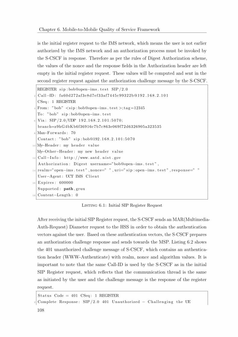
Chapter 6. Mobile-to-Mobile Quality of Service Framework
is the initial register request to the IMS network, which means the user is not earlier
authorized by the IMS network and an authorization process must be invoked by
the S-CSCF in response. Therefore as per the rules of Digest Authorization scheme,
the values of the nonce and the response fields in the Authorization header are left
empty in the initial register request. These values will be computed and sent in the
second register request against the authorization challenge message by the S-CSCF.
REGISTER s i p : bob@open−ims . t e s t SIP /2 .0
2 Call−ID : fa60d272af3e8d7ef33af7445c99322b@192 . 1 6 8 . 2 . 1 0 1
CSeq : 1 REGISTER
4 From : ”bob” <s i p : bob@open−ims . t e s t >; tag =12345
To : ”bob” s i p : bob@open−ims . t e s t
6 Via : SIP /2 .0/UDP 1 9 2 . 1 6 8 . 2 . 1 0 1 : 5 0 7 0 ;
branch=z9hG4bKb6f36916c7b7c863e069f72d6326905a323535
8 Max−Forwards : 70
Contact : ”bob” s i p : bob@192 . 1 6 8 . 2 . 1 0 1 : 5 0 7 0
10 My−Header : my header va lue
My−Other−Header : my new header va lue
12 Call−In f o : http ://www. antd . n i s t . gov
Author i zat ion : Digest username=”bob@open−ims . t e s t ” ,
14 realm=”open−ims . t e s t ” , nonce=” ” , u r i=” s i p : open−ims . t e s t ” , r e sponse=” ”
User−Agent : UCT IMS Cl i en t
16 Expires : 600000
Supported : path , gruu
18 Content−Length : 0
Listing 6.1: Initial SIP Register Request
After receiving the initial SIP Register request, the S-CSCF sends an MAR(Multimedia-
Auth-Request) Diameter request to the HSS in order to obtain the authentication
vectors against the user. Based on these authentication vectors, the S-CSCF prepares
an authorization challenge response and sends towards the MSP. Listing 6.2 shows
the 401 unauthorized challenge message of S-CSCF, which contains an authentica-
tion header (WWW-Authenticate) with realm, nonce and algorithm values. It is
important to note that the same Call-ID is used by the S-CSCF as in the initial
SIP Register request, which reflects that the communication thread is the same
as initiated by the user and the challenge message is the response of the register
request.
Status Code = 401 CSeq : 1 REGISTER
2 Complete Response : SIP /2 .0 401 Unauthorized − Chal leng ing the UE
108
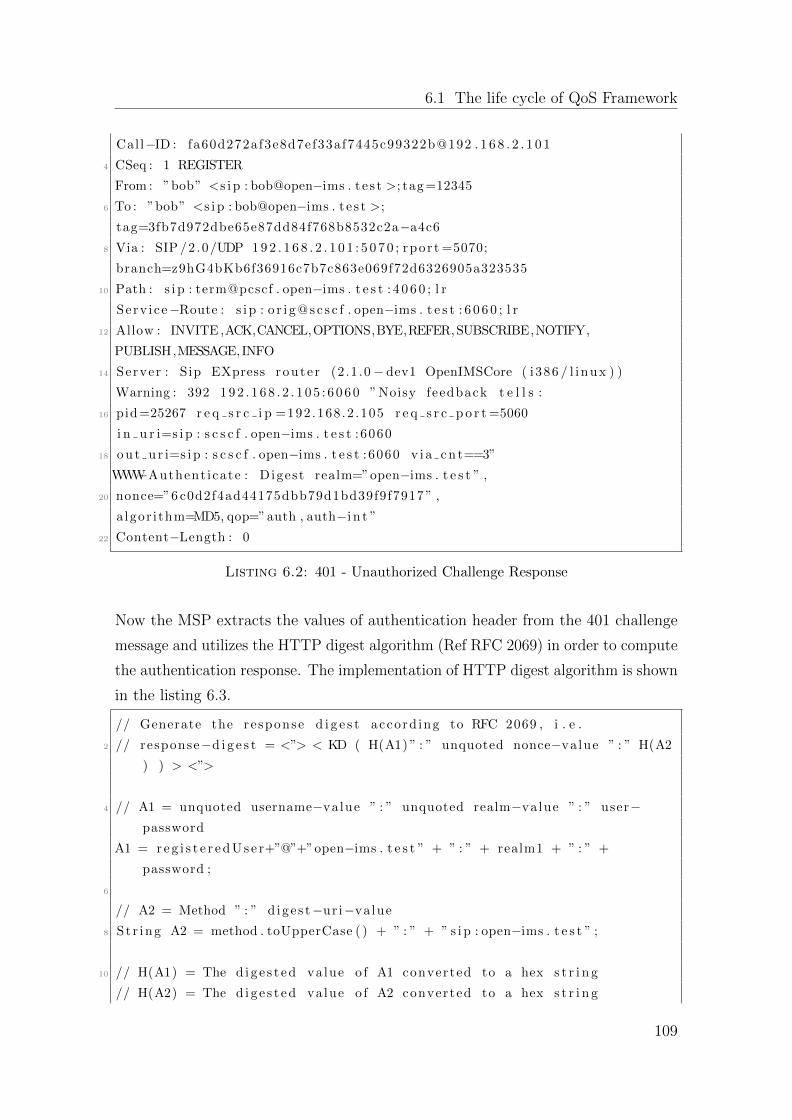
6.1 The life cycle of QoS Framework
Call−ID : fa60d272af3e8d7ef33af7445c99322b@192 . 1 6 8 . 2 . 1 0 1
4 CSeq : 1 REGISTER
From : ”bob” <s i p : bob@open−ims . t e s t >; tag =12345
6 To : ”bob” <s i p : bob@open−ims . t e s t >;
tag=3fb7d972dbe65e87dd84f768b8532c2a−a4c6
8 Via : SIP /2 .0/UDP 1 9 2 . 1 6 8 . 2 . 1 0 1 : 5 0 7 0 ; rpor t =5070;
branch=z9hG4bKb6f36916c7b7c863e069f72d6326905a323535
10 Path : s i p : term@pcscf . open−ims . t e s t : 4 0 6 0 ; l r
Serv i ce−Route : s i p : o r i g @ s c s c f . open−ims . t e s t : 6 0 6 0 ; l r
12 Allow : INVITE ,ACK,CANCEL,OPTIONS,BYE,REFER,SUBSCRIBE,NOTIFY,
PUBLISH,MESSAGE, INFO
14 Server : Sip EXpress route r (2.1 .0− dev1 OpenIMSCore ( i386 / l i nux ) )
Warning : 392 1 9 2 . 1 6 8 . 2 . 1 0 5 : 6 0 6 0 ” Noisy feedback t e l l s :
16 pid =25267 r e q s r c i p =192 .168 .2 .105 r e q s r c p o r t =5060
i n u r i=s i p : s c s c f . open−ims . t e s t :6060
18 o u t u r i=s i p : s c s c f . open−ims . t e s t :6060 v i a c n t==3”
WWW−Authent icate : Digest realm=”open−ims . t e s t ” ,
20 nonce=”6 c0d2f4ad44175dbb79d1bd39f9f7917 ” ,
a lgor i thm=MD5, qop=”auth , auth−i n t ”
22 Content−Length : 0
Listing 6.2: 401 - Unauthorized Challenge Response
Now the MSP extracts the values of authentication header from the 401 challenge
message and utilizes the HTTP digest algorithm (Ref RFC 2069) in order to compute
the authentication response. The implementation of HTTP digest algorithm is shown
in the listing 6.3.
// Generate the re sponse d i g e s t accord ing to RFC 2069 , i . e .
2 // response−d i g e s t = <”> < KD ( H(A1) ” : ” unquoted nonce−value ” : ” H(A2
) ) > <”>
4 // A1 = unquoted username−value ” : ” unquoted realm−value ” : ” user−password
A1 = r e g i s t e r e d U s e r+”@”+”open−ims . t e s t ” + ” : ” + realm1 + ” : ” +
password ;
6
// A2 = Method ” : ” d ige s t−ur i−value
8 St r ing A2 = method . toUpperCase ( ) + ” : ” + ” s i p : open−ims . t e s t ” ;
10 // H(A1) = The d i g e s t ed value o f A1 converted to a hex s t r i n g
// H(A2) = The d i g e s t ed value o f A2 converted to a hex s t r i n g
109
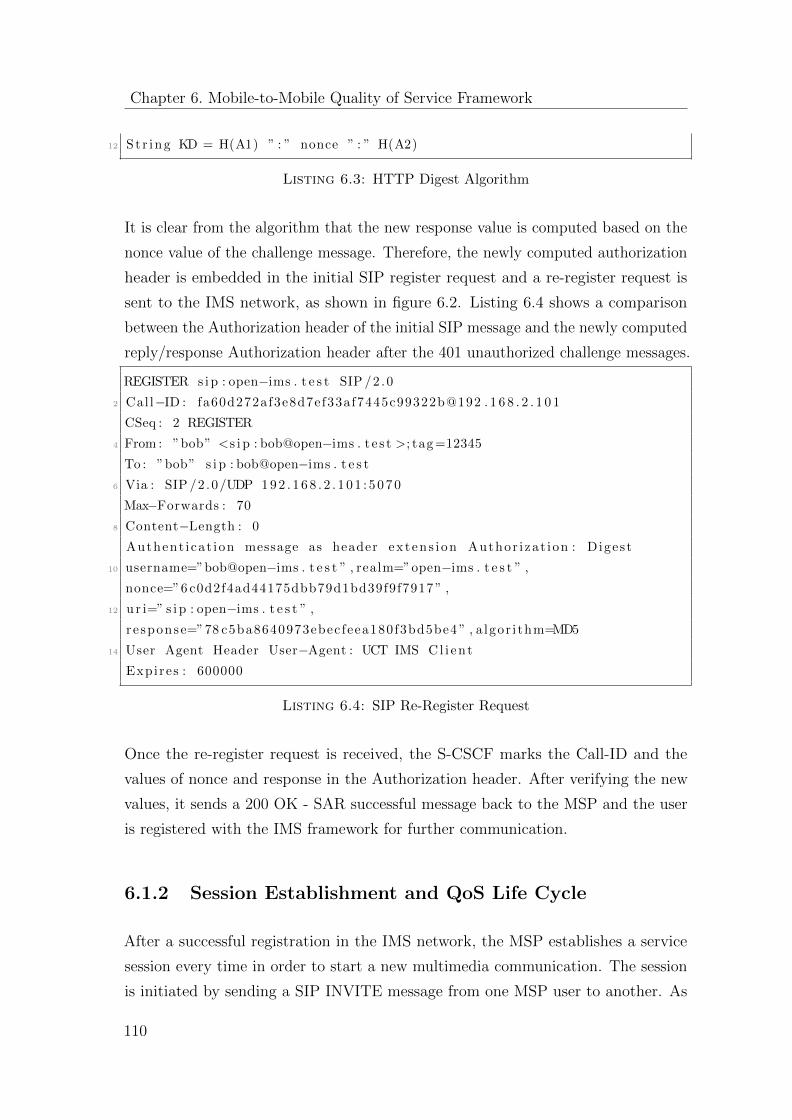
Chapter 6. Mobile-to-Mobile Quality of Service Framework
12 St r ing KD = H(A1) ” : ” nonce ” : ” H(A2)
Listing 6.3: HTTP Digest Algorithm
It is clear from the algorithm that the new response value is computed based on the
nonce value of the challenge message. Therefore, the newly computed authorization
header is embedded in the initial SIP register request and a re-register request is
sent to the IMS network, as shown in figure 6.2. Listing 6.4 shows a comparison
between the Authorization header of the initial SIP message and the newly computed
reply/response Authorization header after the 401 unauthorized challenge messages.
REGISTER s i p : open−ims . t e s t SIP /2 .0
2 Call−ID : fa60d272af3e8d7ef33af7445c99322b@192 . 1 6 8 . 2 . 1 0 1
CSeq : 2 REGISTER
4 From : ”bob” <s i p : bob@open−ims . t e s t >; tag =12345
To : ”bob” s i p : bob@open−ims . t e s t
6 Via : SIP /2 .0/UDP 1 9 2 . 1 6 8 . 2 . 1 0 1 : 5 0 7 0
Max−Forwards : 70
8 Content−Length : 0
Authent icat ion message as header ex tens i on Author i zat ion : Digest
10 username=”bob@open−ims . t e s t ” , realm=”open−ims . t e s t ” ,
nonce=”6 c0d2f4ad44175dbb79d1bd39f9f7917 ” ,
12 u r i=” s i p : open−ims . t e s t ” ,
r e sponse=”78 c5ba8640973ebecfeea180f3bd5be4 ” , a lgor i thm=MD5
14 User Agent Header User−Agent : UCT IMS Cl i en t
Expires : 600000
Listing 6.4: SIP Re-Register Request
Once the re-register request is received, the S-CSCF marks the Call-ID and the
values of nonce and response in the Authorization header. After verifying the new
values, it sends a 200 OK - SAR successful message back to the MSP and the user
is registered with the IMS framework for further communication.
6.1.2 Session Establishment and QoS Life Cycle
After a successful registration in the IMS network, the MSP establishes a service
session every time in order to start a new multimedia communication. The session
is initiated by sending a SIP INVITE message from one MSP user to another. As
110
6.1 The life cycle of QoS Framework
explained in section 4.2.2.1 , an SDP offer is also sent inside the INVITE message
which includes all supported codecs required to make a multimedia call between the
two parties.
As shown in figure 6.3, the INVITE message form the originating MSP is received
by the P-CSCF in the terminating IMS network. Before forwarding the INVITE
message to the terminating MSP, the terminating P-CSCF first reads the media
related information from the SDP offer and then requests a media authorization
token (MAT) from the policy controller (PCRF) in order to check whether the
terminating party is authorized to the requested media types and codecs. If the
P-CSCF determines that a certain media type or codec should not be used in this
session, an immediate rejection will be sent to the MSP by the P-CSCF. Otherwise,
the INVITE message is sent to the terminating MSP. The terminating MSP receives
this MAT in the INVITE message which needs to be passed to the network gateway
(PCEF/PGW) later for resource reservation purpose.
The MSP prepares a common list of media codecs from the SDP offer and sends
it back via a 183 progress message. Once the 183 progress message reaches the
originating IMS network, the originating P-CSCF repeats the media authorization
process and a MAT is sent to the originating MSP for resource reservation purpose.
6.1.3 QoS Differentiation Based on User Profiles and Ser-
vice Types
Listing 6.5 shows a sample INVITE message with a complete SDP media description
and QoS information embedded in the SIP body. The QoS pre-conditions, such
as the lines a=curr:qos lines, indicate the actual and the current situation of the
end parties that whether the resources needed for meeting the quality of service
requirements are available or not. Whereas, the a=des:qos lines indicate the desired
quality of service requirements needed for a particular multimedia session. Here, the
lines ”a=curr:qos local none” and ”a=curr:qos remote none”, indicate that there is
no QoS terms and conditions determined between two parties at the moment.
Additionally, the dissertation proposes two new QoS related headers in the body
of the SIP message: QoS-class-user and QoS-class-service. The motivation behind
the introduction of these headers is to let the operators control the network traffic
111
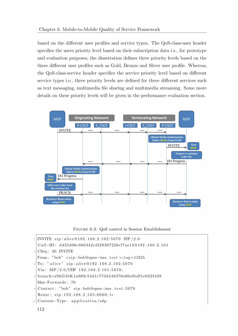
Chapter 6. Mobile-to-Mobile Quality of Service Framework
based on the different user profiles and service types. The QoS-class-user header
specifies the users priority level based on their subscription data i.e., for prototype
and evaluation purposes, the dissertation defines three priority levels based on the
three different user profiles such as Gold, Bronze and Sliver user profile. Whereas,
the QoS-class-service header specifies the service priority level based on different
service types i.e., three priority levels are defined for three different services such
as text messaging, multimedia file sharing and multimedia streaming. Some more
details on these priority levels will be given in the performance evaluation section.
MSP MSP
P-CSCF S_CSCF P-CSCFI-CSCF S_CSCF
Terminating NetworkOriginating Network
INVITE ..... ..... ..... .....
INVITE
Obtain Media Authorization
Token (MAT) from PCRF
Prepare a common
codec list
Obtain Media Authorization
Token (MAT) from PCRF
Select one codec from
the common list
183 Progress
183 Progress
..... ..... ..... .....
Save
MAT
Save
MAT
PRACK ..... ..... ..... ..... .....
Resource Reservation
using MAT Resource Reservation
using MAT
Figure 6.3: QoS control in Session Establishment
1 INVITE s i p : a l i ce@192 . 1 6 8 . 2 . 1 0 2 : 5 0 7 0 SIP /2 .0
Cal l−ID : d425d06c866342cdf29397226cf7ae14@192 . 1 6 8 . 2 . 1 0 1
3 CSeq : 20 INVITE
From : ”bob” <s i p : bob@open−ims . t e s t >; tag =12345
5 To : ” a l i c e ” s i p : a l i ce@192 . 1 6 8 . 2 . 1 0 2 : 5 0 7 0
Via : SIP /2 .0/UDP 1 9 2 . 1 6 8 . 2 . 1 0 1 : 5 0 7 0 ;
7 branch=z9hG4bK1a089c54d1c77dd448370e60e0bdf1e0323439
Max−Forwards : 70
9 Contact : ”bob” s i p : bob@open−ims . t e s t :5070
Route : s i p : 1 9 2 . 1 6 8 . 2 . 1 0 5 : 6 0 6 0 ; l r
11 Content−Type : a p p l i c a t i o n /sdp
112
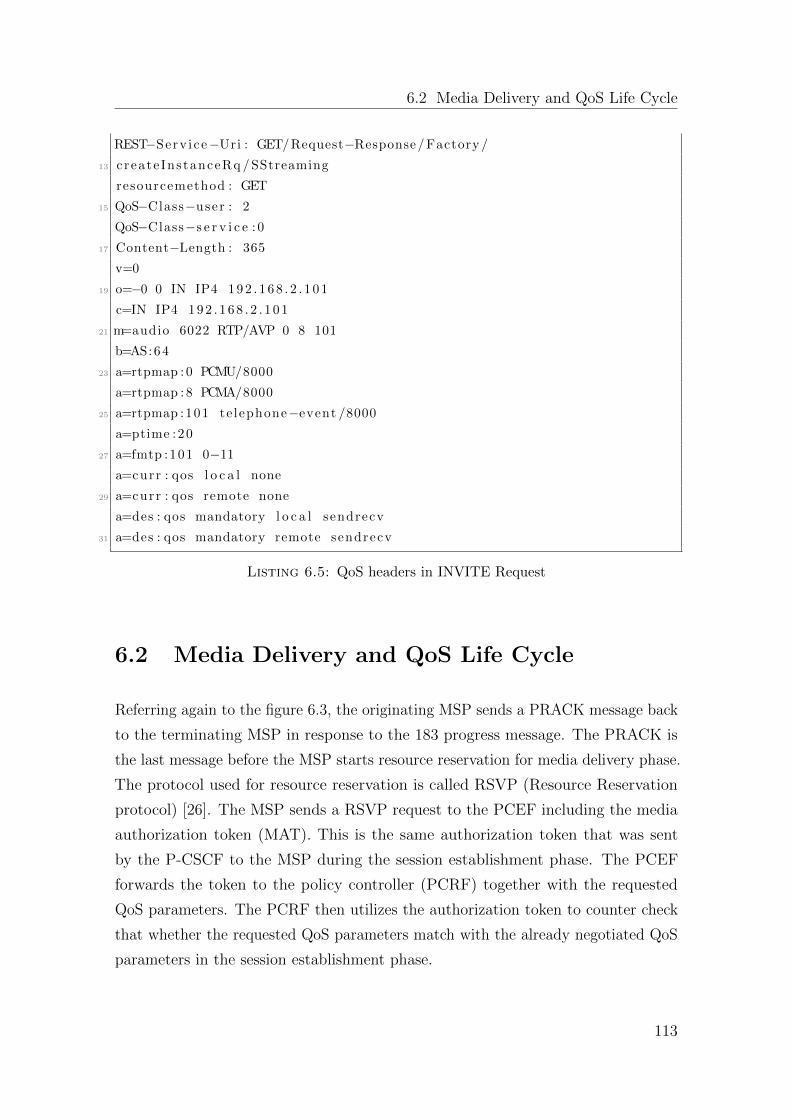
6.2 Media Delivery and QoS Life Cycle
REST−Serv ice−Uri : GET/Request−Response/ Factory /
13 create InstanceRq / SStreaming
resourcemethod : GET
15 QoS−Class−user : 2
QoS−Class−s e r v i c e : 0
17 Content−Length : 365
v=0
19 o=−0 0 IN IP4 1 9 2 . 1 6 8 . 2 . 1 0 1
c=IN IP4 1 9 2 . 1 6 8 . 2 . 1 0 1
21 m=audio 6022 RTP/AVP 0 8 101
b=AS:64
23 a=rtpmap : 0 PCMU/8000
a=rtpmap : 8 PCMA/8000
25 a=rtpmap :101 te lephone−event /8000
a=ptime :20
27 a=fmtp :101 0−11
a=curr : qos l o c a l none
29 a=curr : qos remote none
a=des : qos mandatory l o c a l sendrecv
31 a=des : qos mandatory remote sendrecv
Listing 6.5: QoS headers in INVITE Request
6.2 Media Delivery and QoS Life Cycle
Referring again to the figure 6.3, the originating MSP sends a PRACK message back
to the terminating MSP in response to the 183 progress message. The PRACK is
the last message before the MSP starts resource reservation for media delivery phase.
The protocol used for resource reservation is called RSVP (Resource Reservation
protocol) [26]. The MSP sends a RSVP request to the PCEF including the media
authorization token (MAT). This is the same authorization token that was sent
by the P-CSCF to the MSP during the session establishment phase. The PCEF
forwards the token to the policy controller (PCRF) together with the requested
QoS parameters. The PCRF then utilizes the authorization token to counter check
that whether the requested QoS parameters match with the already negotiated QoS
parameters in the session establishment phase.
113
Chapter 6. Mobile-to-Mobile Quality of Service Framework
This is the final authorization check performed by the network to allocate the
resources for the upcoming media delivery session. Finally, the PCRF takes the
policy decision and informs the PCEF that the MSP is allowed to use the allocated
QoS resources. The PCEF then enforces the policy decision and allows the MSP to
start multimedia traffic.
6.3 Evaluations
With the inclusion of QoS framework in the MSP, an extensive study is carried out
to analyze its impact on the individual services. A systematic approach is adopted
in order to study the session establishment and media delivery latencies for different
user profiles and service types. For evaluation purpose, three different user profiles
are created in the MSP:
Gold user profile: Gold user profile reflects to the user category who receive best
available network conditions throughout the service session.
Silver user profile: Bronze user profile point to the user category who experience
some network disruption (packet delay, Jitter, etc) during the service session.
Bronze user profile: This profile illustrates the user category who experience
major network disruption and traffic irregularities during the service session.
6.3.1 Testbed
The testbed setup is consisted of two user terminals and one server machine acting
as an IMS server. The configuration of the testbed is as follows:
User Terminal - 1 with MSP:
Model: HTC Legend
Platform: Android 2.2
Camera: 5-megapixel color camera with auto focus and flash
Memory: ROM: 512MB RAM: 384MB
CPU Speed: 600MHz
114
6.3 Evaluations
User Terminal - 2 with MSP:
Model: Samsung Galaxy S3 (i900)
Platform: Android 4.1.2 (Jelly Bean)
Camera: 6-megapixel color camera with auto focus
Memory: ROM: 16 GB RAM: 1 GB
CPU Speed: Quad-core 1.4 GHz
Server Machine with IMS Testbed:
Fraunhofer FOKUS OpenIMS Core is used as an IMS testbed. It comes as an Eclipse
plug-in. It was running on the machine with the following specifications.
System Manufacturer: IBM
Model: Lenovo T41
Processor: Intel 1.7 GHz
Memory: RAM: 1 GB
Operating System: Linux Ubuntu 12.04
IDE: Eclipse JUNO
Video Sources:
Two video files were selected for the evaluation purpose:
Video 1:
Source: http://m.youtube.com/watch?client=mv-google
Length of video: 1:00 min
Name of video: Android in Space
Video 2:
Source: http://www.youtube.com/watch?v=QHIzzQB4Lew
Length of video: 0:45 second
Name of video: New Skype for Android
File Sources:
Two image files were selected for the evaluation purpose:
File 1:
Source: Own Camera Picture
115
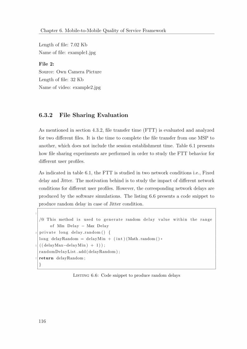
Chapter 6. Mobile-to-Mobile Quality of Service Framework
Length of file: 7.02 Kb
Name of file: example1.jpg
File 2:
Source: Own Camera Picture
Length of file: 32 Kb
Name of video: example2.jpg
6.3.2 File Sharing Evaluation
As mentioned in section 4.3.2, file transfer time (FTT) is evaluated and analyzed
for two different files. It is the time to complete the file transfer from one MSP to
another, which does not include the session establishment time. Table 6.1 presents
how file sharing experiments are performed in order to study the FTT behavior for
different user profiles.
As indicated in table 6.1, the FTT is studied in two network conditions i.e., Fixed
delay and Jitter. The motivation behind is to study the impact of different network
conditions for different user profiles. However, the corresponding network delays are
produced by the software simulations. The listing 6.6 presents a code snippet to
produce random delay in case of Jitter condition.
1
/@ This method i s used to generate random delay value with in the range
o f Min Delay − Max Delay
3 p r i v a t e long delay random ( ) {long delayRandom = delayMin + ( i n t ) (Math . random ( ) *
5 ( ( delayMax−delayMin ) + 1) ) ;
randomDelayList . add ( delayRandom ) ;
7 return delayRandom ;
}
Listing 6.6: Code snippet to produce random delays
116
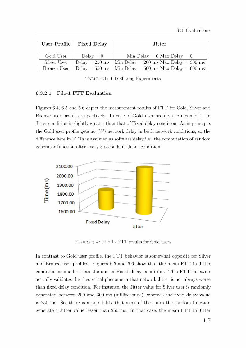
6.3 Evaluations
User Profile Fixed Delay Jitter
Gold User Delay = 0 Min Delay = 0 Max Delay = 0Silver User Delay = 250 ms Min Delay = 200 ms Max Delay = 300 ms
Bronze User Delay = 550 ms Min Delay = 500 ms Max Delay = 600 ms
Table 6.1: File Sharing Experiments
6.3.2.1 File-1 FTT Evaluation
Figures 6.4, 6.5 and 6.6 depict the measurement results of FTT for Gold, Silver and
Bronze user profiles respectively. In case of Gold user profile, the mean FTT in
Jitter condition is slightly greater than that of Fixed delay condition. As in principle,
the Gold user profile gets no (’0’) network delay in both network conditions, so the
difference here in FTTs is assumed as software delay i.e., the computation of random
generator function after every 3 seconds in Jitter condition.
Figure 6.4: File 1 - FTT results for Gold users
In contrast to Gold user profile, the FTT behavior is somewhat opposite for Silver
and Bronze user profiles. Figures 6.5 and 6.6 show that the mean FTT in Jitter
condition is smaller than the one in Fixed delay condition. This FTT behavior
actually validates the theoretical phenomena that network Jitter is not always worse
than fixed delay condition. For instance, the Jitter value for Silver user is randomly
generated between 200 and 300 ms (milliseconds), whereas the fixed delay value
is 250 ms. So, there is a possibility that most of the times the random function
generate a Jitter value lesser than 250 ms. In that case, the mean FTT in Jitter
117
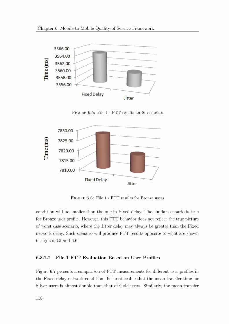
Chapter 6. Mobile-to-Mobile Quality of Service Framework
Figure 6.5: File 1 - FTT results for Silver users
Figure 6.6: File 1 - FTT results for Bronze users
condition will be smaller than the one in Fixed delay. The similar scenario is true
for Bronze user profile. However, this FTT behavior does not reflect the true picture
of worst case scenario, where the Jitter delay may always be greater than the Fixed
network delay. Such scenario will produce FTT results opposite to what are shown
in figures 6.5 and 6.6.
6.3.2.2 File-1 FTT Evaluation Based on User Profiles
Figure 6.7 presents a comparison of FTT measurements for different user profiles in
the Fixed delay network condition. It is noticeable that the mean transfer time for
Silver users is almost double than that of Gold users. Similarly, the mean transfer
118
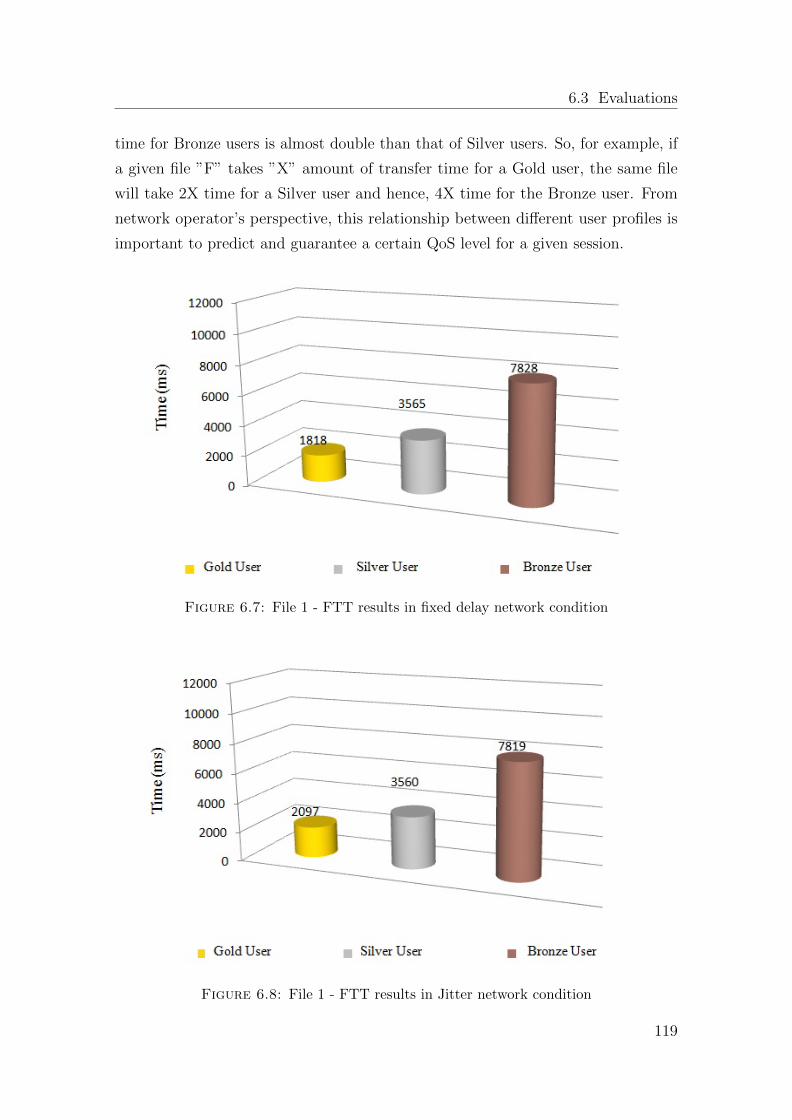
6.3 Evaluations
time for Bronze users is almost double than that of Silver users. So, for example, if
a given file ”F” takes ”X” amount of transfer time for a Gold user, the same file
will take 2X time for a Silver user and hence, 4X time for the Bronze user. From
network operator’s perspective, this relationship between different user profiles is
important to predict and guarantee a certain QoS level for a given session.
Figure 6.7: File 1 - FTT results in fixed delay network condition
Figure 6.8: File 1 - FTT results in Jitter network condition
119
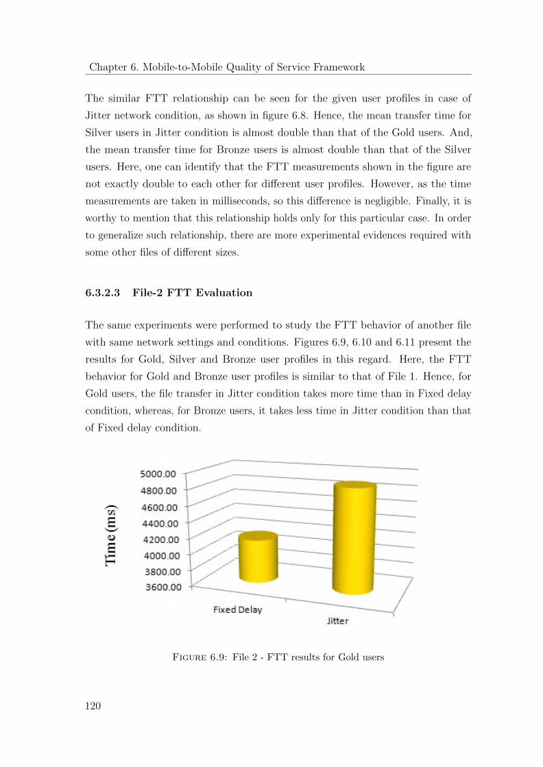
Chapter 6. Mobile-to-Mobile Quality of Service Framework
The similar FTT relationship can be seen for the given user profiles in case of
Jitter network condition, as shown in figure 6.8. Hence, the mean transfer time for
Silver users in Jitter condition is almost double than that of the Gold users. And,
the mean transfer time for Bronze users is almost double than that of the Silver
users. Here, one can identify that the FTT measurements shown in the figure are
not exactly double to each other for different user profiles. However, as the time
measurements are taken in milliseconds, so this difference is negligible. Finally, it is
worthy to mention that this relationship holds only for this particular case. In order
to generalize such relationship, there are more experimental evidences required with
some other files of different sizes.
6.3.2.3 File-2 FTT Evaluation
The same experiments were performed to study the FTT behavior of another file
with same network settings and conditions. Figures 6.9, 6.10 and 6.11 present the
results for Gold, Silver and Bronze user profiles in this regard. Here, the FTT
behavior for Gold and Bronze user profiles is similar to that of File 1. Hence, for
Gold users, the file transfer in Jitter condition takes more time than in Fixed delay
condition, whereas, for Bronze users, it takes less time in Jitter condition than that
of Fixed delay condition.
Figure 6.9: File 2 - FTT results for Gold users
120
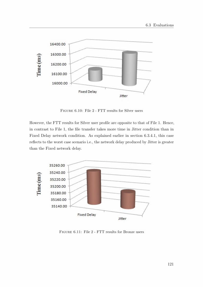
6.3 Evaluations
Figure 6.10: File 2 - FTT results for Silver users
However, the FTT results for Silver user profile are opposite to that of File 1. Hence,
in contrast to File 1, the file transfer takes more time in Jitter condition than in
Fixed Delay network condition. As explained earlier in section 6.3.4.1, this case
reflects to the worst case scenario i.e., the network delay produced by Jitter is greater
than the Fixed network delay.
Figure 6.11: File 2 - FTT results for Bronze users
121
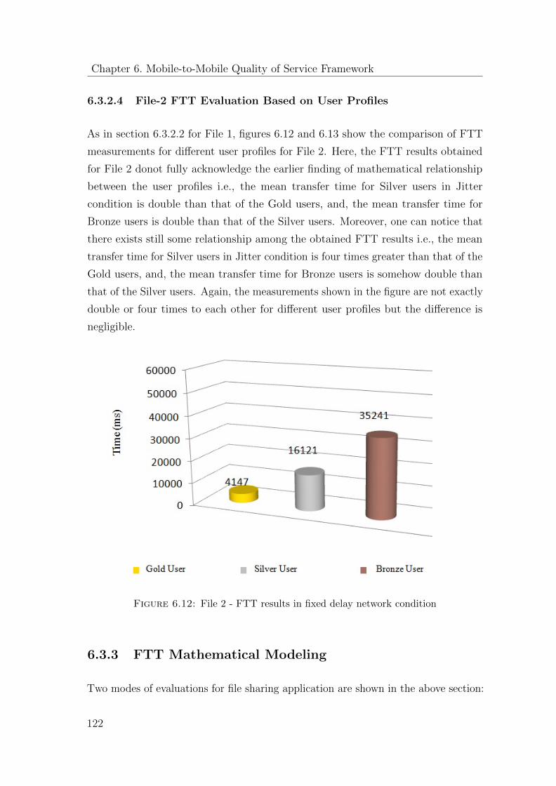
Chapter 6. Mobile-to-Mobile Quality of Service Framework
6.3.2.4 File-2 FTT Evaluation Based on User Profiles
As in section 6.3.2.2 for File 1, figures 6.12 and 6.13 show the comparison of FTT
measurements for different user profiles for File 2. Here, the FTT results obtained
for File 2 donot fully acknowledge the earlier finding of mathematical relationship
between the user profiles i.e., the mean transfer time for Silver users in Jitter
condition is double than that of the Gold users, and, the mean transfer time for
Bronze users is double than that of the Silver users. Moreover, one can notice that
there exists still some relationship among the obtained FTT results i.e., the mean
transfer time for Silver users in Jitter condition is four times greater than that of the
Gold users, and, the mean transfer time for Bronze users is somehow double than
that of the Silver users. Again, the measurements shown in the figure are not exactly
double or four times to each other for different user profiles but the difference is
negligible.
Figure 6.12: File 2 - FTT results in fixed delay network condition
6.3.3 FTT Mathematical Modeling
Two modes of evaluations for file sharing application are shown in the above section:
122
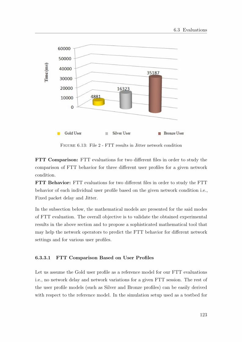
6.3 Evaluations
Figure 6.13: File 2 - FTT results in Jitter network condition
FTT Comparison: FTT evaluations for two different files in order to study the
comparison of FTT behavior for three different user profiles for a given network
condition.
FTT Behavior: FTT evaluations for two different files in order to study the FTT
behavior of each individual user profile based on the given network condition i.e.,
Fixed packet delay and Jitter.
In the subsection below, the mathematical models are presented for the said modes
of FTT evaluation. The overall objective is to validate the obtained experimental
results in the above section and to propose a sophisticated mathematical tool that
may help the network operators to predict the FTT behavior for different network
settings and for various user profiles.
6.3.3.1 FTT Comparison Based on User Profiles
Let us assume the Gold user profile as a reference model for our FTT evaluations
i.e., no network delay and network variations for a given FTT session. The rest of
the user profile models (such as Silver and Bronze profiles) can be easily derived
with respect to the reference model. In the simulation setup used as a testbed for
123
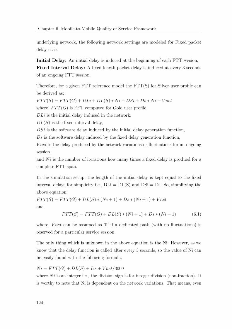
Chapter 6. Mobile-to-Mobile Quality of Service Framework
underlying network, the following network settings are modeled for Fixed packet
delay case:
Initial Delay: An initial delay is induced at the beginning of each FTT session.
Fixed Interval Delay: A fixed length packet delay is induced at every 3 seconds
of an ongoing FTT session.
Therefore, for a given FTT reference model the FTT(S) for Silver user profile can
be derived as:
FTT (S) = FTT (G) + DLi + DL(S) ∗Ni + DSi + Ds ∗Ni + V net
where, FTT (G) is FFT computed for Gold user profile,
DLi is the initial delay induced in the network,
DL(S) is the fixed interval delay,
DSi is the software delay induced by the initial delay generation function,
Ds is the software delay induced by the fixed delay generation function,
V net is the delay produced by the network variations or fluctuations for an ongoing
session,
and Ni is the number of iterations how many times a fixed delay is produed for a
complete FTT span.
In the simulation setup, the length of the initial delay is kept equal to the fixed
interval delays for simplicity i.e., DLi = DL(S) and DSi = Ds. So, simplifying the
above equation:
FTT (S) = FTT (G) + DL(S) ∗ (Ni + 1) + Ds ∗ (Ni + 1) + V net
and
FTT (S) = FTT (G) + DL(S) ∗ (Ni + 1) + Ds ∗ (Ni + 1) (6.1)
where, V net can be assumed as ’0’ if a dedicated path (with no fluctuations) is
reserved for a particular service session.
The only thing which is unknown in the above equation is the Ni. However, as we
know that the delay function is called after every 3 seconds, so the value of Ni can
be easily found with the following formula.
Ni = FTT (G) + DL(S) + Ds + V net/3000
where Ni is an integer i.e., the division sign is for integer division (non-fraction). It
is worthy to note that Ni is dependent on the network variations. That means, even
124
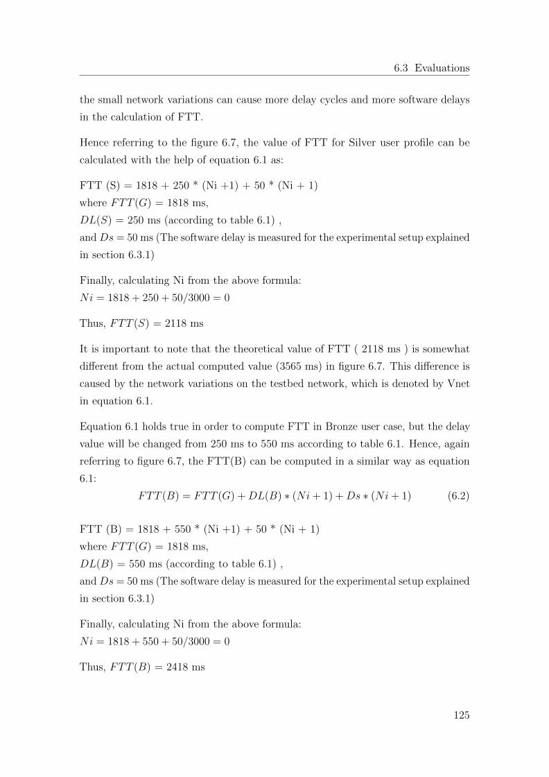
6.3 Evaluations
the small network variations can cause more delay cycles and more software delays
in the calculation of FTT.
Hence referring to the figure 6.7, the value of FTT for Silver user profile can be
calculated with the help of equation 6.1 as:
FTT (S) = 1818 + 250 * (Ni +1) + 50 * (Ni + 1)
where FTT (G) = 1818 ms,
DL(S) = 250 ms (according to table 6.1) ,
and Ds = 50 ms (The software delay is measured for the experimental setup explained
in section 6.3.1)
Finally, calculating Ni from the above formula:
Ni = 1818 + 250 + 50/3000 = 0
Thus, FTT (S) = 2118 ms
It is important to note that the theoretical value of FTT ( 2118 ms ) is somewhat
different from the actual computed value (3565 ms) in figure 6.7. This difference is
caused by the network variations on the testbed network, which is denoted by Vnet
in equation 6.1.
Equation 6.1 holds true in order to compute FTT in Bronze user case, but the delay
value will be changed from 250 ms to 550 ms according to table 6.1. Hence, again
referring to figure 6.7, the FTT(B) can be computed in a similar way as equation
6.1:
FTT (B) = FTT (G) + DL(B) ∗ (Ni + 1) + Ds ∗ (Ni + 1) (6.2)
FTT (B) = 1818 + 550 * (Ni +1) + 50 * (Ni + 1)
where FTT (G) = 1818 ms,
DL(B) = 550 ms (according to table 6.1) ,
and Ds = 50 ms (The software delay is measured for the experimental setup explained
in section 6.3.1)
Finally, calculating Ni from the above formula:
Ni = 1818 + 550 + 50/3000 = 0
Thus, FTT (B) = 2418 ms
125
Chapter 6. Mobile-to-Mobile Quality of Service Framework
Equation 6.1 still holds true for computing FTT in Jitter conditions, but the delay
is a random variable in this case with the possible outcome in the range specified in
the table 6.1. A more detailed analysis of FTT in Jitter conditions is presented in
the following section.
6.3.3.2 FTT Behavior for Different Network Conditions
For a given reference model of Gold user profile, the value of FTT for Fixed packet
delay and for Jitter network condition should be ideally same since there is no
network delay and variations assumed. However, in the given simulation setup there
is a possibility of slight variation in the FTT values due to software delay variations
of both fixed delay function and a random delay function. Here, one can argue that
there is no need of executing delay functions in the Gold user case. But, on the
contrary, the delay functions are still executed to produce an initial delay of ’0’ value
in the given simulation setup. Therefore, the FTT relation for different network
settings can be derived as:
FTT (J) = FTT (D) + V soft Gold User Profile (6.3)
where, FTT (J) is the FTT value in Jitter network condition,
FFT (D) is the FTT value for fixed packet delay network condition
and V soft is the delay variations in executing the two software functions.
The above relationship can be validated from the experimental results shown in
figures 6.4 and 6.9. On the contrary, for Silver and Bronze user profiles the FTT(J)
and FTT(D) relationship is highly dependent on the sum of the individual delays for
a given FTT session produced by the random generator function for Jitter network
condition. For instance assuming the Vsoft as ’0’ for real network case, if the sum
of individual random delays is equal to the sum of the individual fixed delays then
the value of FFT (J) and FFT (D) will be the same. Similarly, the FFT (J) will
be greater or less than FFT (D) if the sum of individual random delays would be
greater or less than the sum of the individual fixed delays. Hence, this relationship
can be mathematically modeled as:
126
6.3 Evaluations
FTT (J)
> FTT (D), if(
∑nx=1DLfx >
∑nx=1DLjx)
< FTT (D), if(∑n
x=1DLfx <∑n
x=1DLjx) Silver User Profile
= FTT (D), if(∑n
x=1DLfx =∑n
x=1DLjx)
(6.4)
FTT (J)
> FTT (D), if(
∑nx=1DLfx >
∑nx=1DLjx)
< FTT (D), if(∑n
x=1DLfx <∑n
x=1DLjx) Bronze User Profile
= FTT (D), if(∑n
x=1DLfx =∑n
x=1DLjx)
(6.5)
6.3.4 Multimedia Streaming Evaluation
As mentioned in section 5.5, this section presents the evaluation and analysis of
video streaming time (VST) of two different videos for different user profiles. Since
multimedia streaming services are highly delay sensitive services, the Jitter network
condition is further divided into two categories: Periodic Jitter, where a Jitter is
produced every time after a fixed period of time throughout the video streaming.
Non-Periodic Jitter, represents a Jitter which is produced every time after a variable
period of time throughout the video streaming. Table 6.2 presents how video
streaming experiments are performed for different user profiles.
6.3.4.1 Video-1 VST Evaluation
Figures 6.14, 6.15 and 6.16 depict the measurement results of VST for Gold, Silver
and Bronze user profiles respectively. In case of Gold user profile, the mean VST
in Periodic Jitter condition is slightly greater than that of Fixed delay condition.
Similarly, the mean VST in Non-Periodic Jitter condition is greater than that of
Periodic Jitter condition. As in principle, the Gold user profile gets no (’0’) network
delay in any network condition, hence, the differences here in streaming times will
be assumed as software delays i.e., the computation of random generator function
before every delay.
127
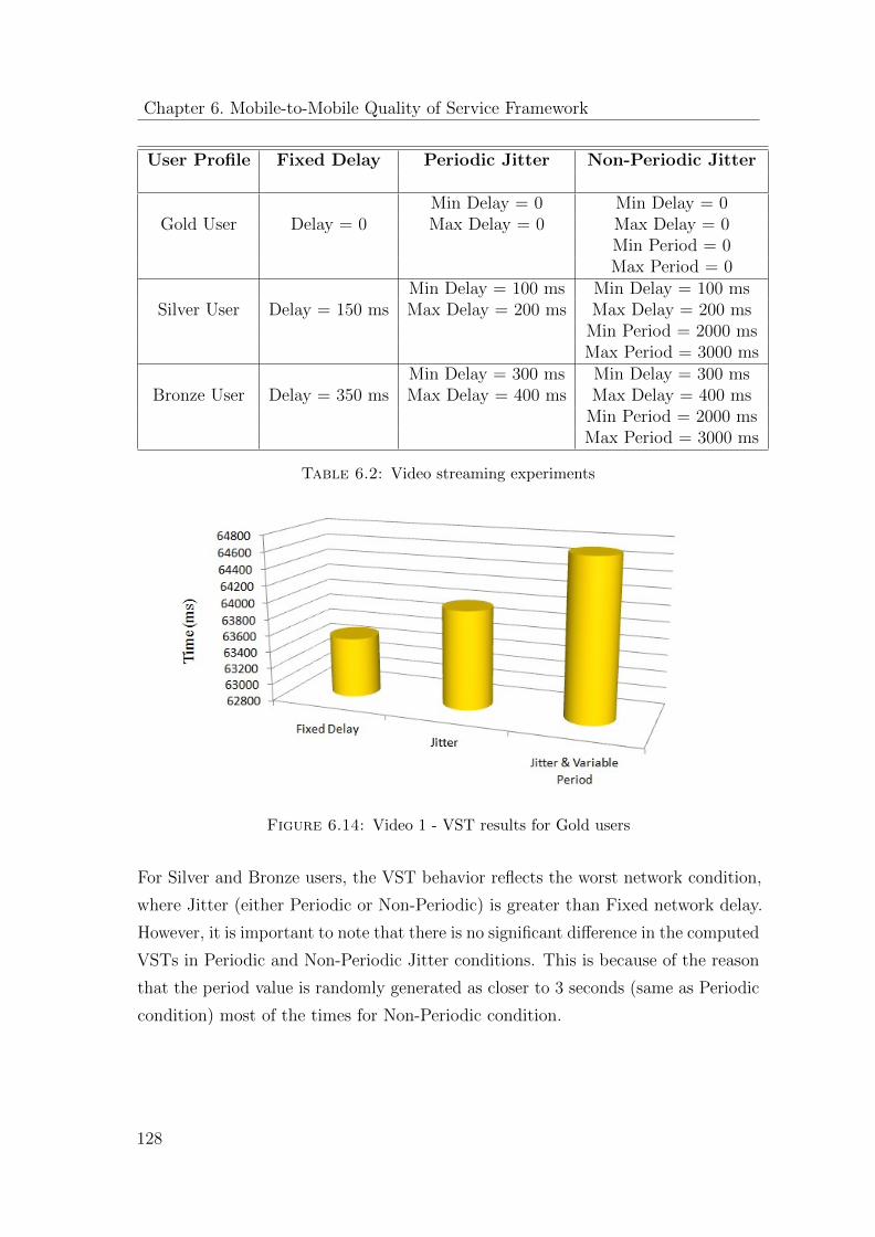
Chapter 6. Mobile-to-Mobile Quality of Service Framework
User Profile Fixed Delay Periodic Jitter Non-Periodic Jitter
Min Delay = 0 Min Delay = 0Gold User Delay = 0 Max Delay = 0 Max Delay = 0
Min Period = 0Max Period = 0
Min Delay = 100 ms Min Delay = 100 msSilver User Delay = 150 ms Max Delay = 200 ms Max Delay = 200 ms
Min Period = 2000 msMax Period = 3000 ms
Min Delay = 300 ms Min Delay = 300 msBronze User Delay = 350 ms Max Delay = 400 ms Max Delay = 400 ms
Min Period = 2000 msMax Period = 3000 ms
Table 6.2: Video streaming experiments
Figure 6.14: Video 1 - VST results for Gold users
For Silver and Bronze users, the VST behavior reflects the worst network condition,
where Jitter (either Periodic or Non-Periodic) is greater than Fixed network delay.
However, it is important to note that there is no significant difference in the computed
VSTs in Periodic and Non-Periodic Jitter conditions. This is because of the reason
that the period value is randomly generated as closer to 3 seconds (same as Periodic
condition) most of the times for Non-Periodic condition.
128
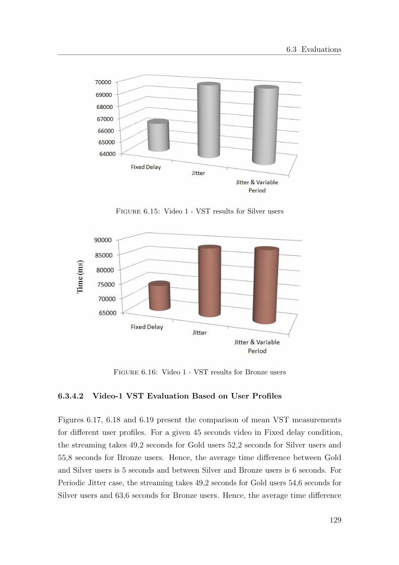
6.3 Evaluations
Figure 6.15: Video 1 - VST results for Silver users
Figure 6.16: Video 1 - VST results for Bronze users
6.3.4.2 Video-1 VST Evaluation Based on User Profiles
Figures 6.17, 6.18 and 6.19 present the comparison of mean VST measurements
for different user profiles. For a given 45 seconds video in Fixed delay condition,
the streaming takes 49,2 seconds for Gold users 52,2 seconds for Silver users and
55,8 seconds for Bronze users. Hence, the average time difference between Gold
and Silver users is 5 seconds and between Silver and Bronze users is 6 seconds. For
Periodic Jitter case, the streaming takes 49,2 seconds for Gold users 54,6 seconds for
Silver users and 63,6 seconds for Bronze users. Hence, the average time difference
129
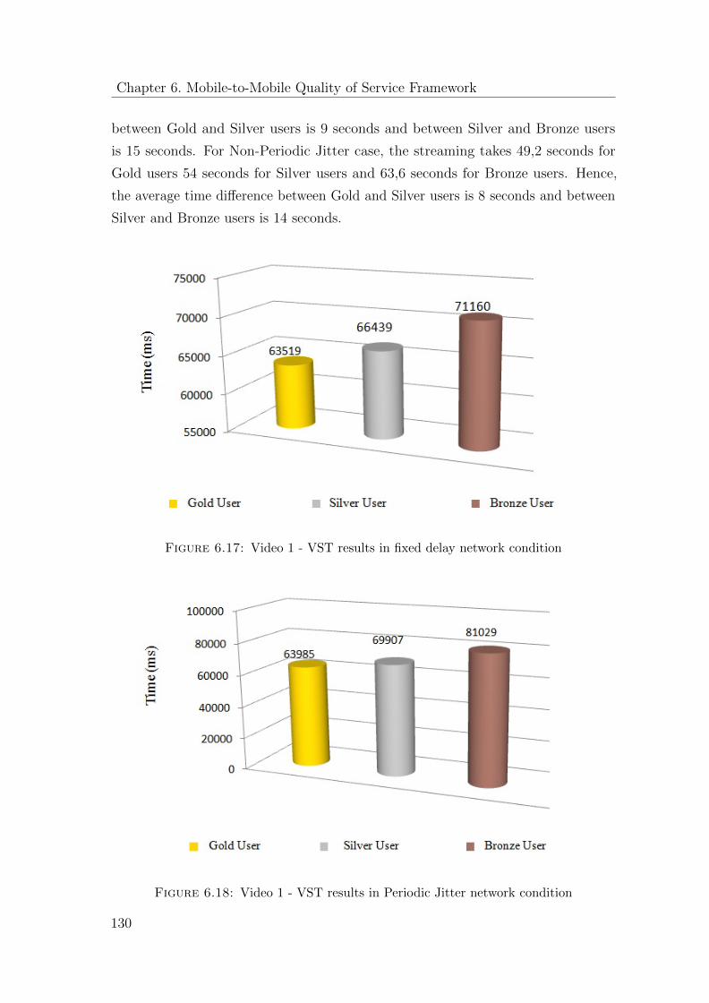
Chapter 6. Mobile-to-Mobile Quality of Service Framework
between Gold and Silver users is 9 seconds and between Silver and Bronze users
is 15 seconds. For Non-Periodic Jitter case, the streaming takes 49,2 seconds for
Gold users 54 seconds for Silver users and 63,6 seconds for Bronze users. Hence,
the average time difference between Gold and Silver users is 8 seconds and between
Silver and Bronze users is 14 seconds.
Figure 6.17: Video 1 - VST results in fixed delay network condition
Figure 6.18: Video 1 - VST results in Periodic Jitter network condition
130
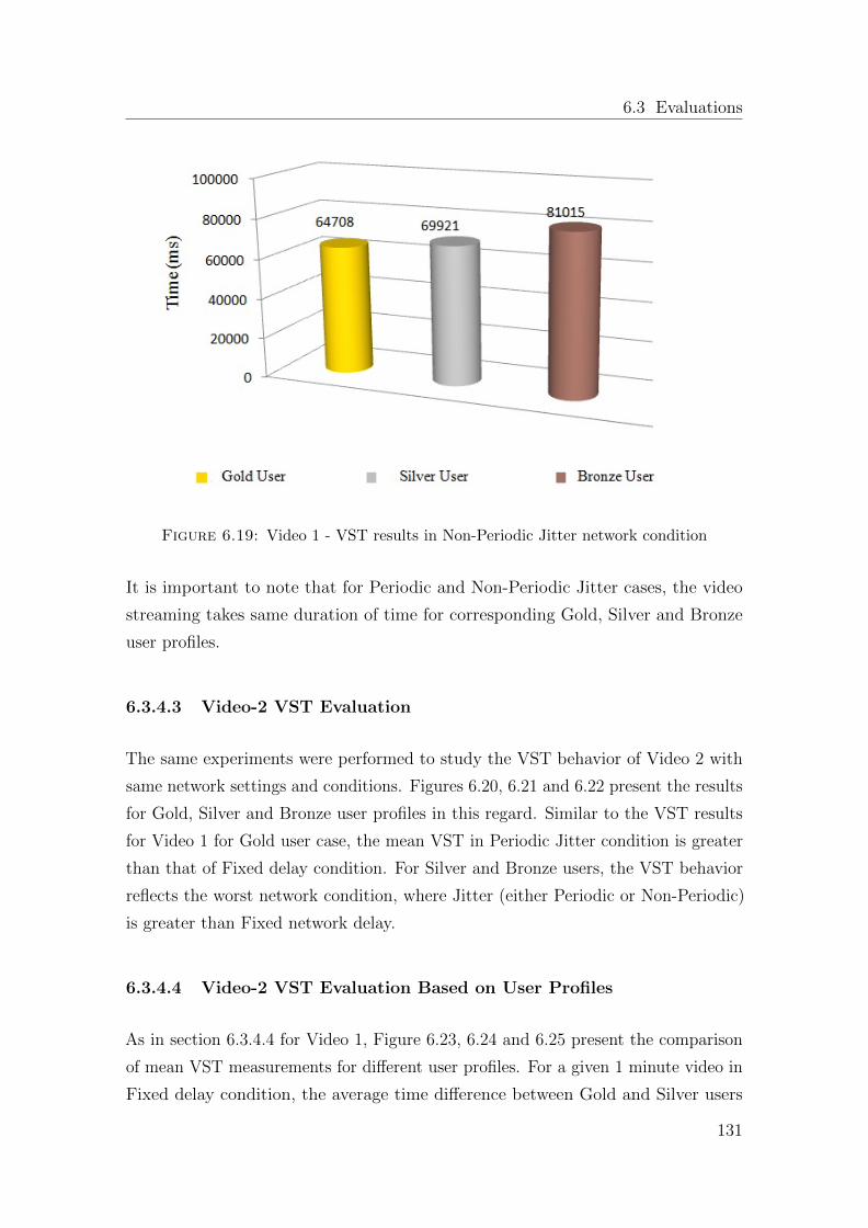
6.3 Evaluations
Figure 6.19: Video 1 - VST results in Non-Periodic Jitter network condition
It is important to note that for Periodic and Non-Periodic Jitter cases, the video
streaming takes same duration of time for corresponding Gold, Silver and Bronze
user profiles.
6.3.4.3 Video-2 VST Evaluation
The same experiments were performed to study the VST behavior of Video 2 with
same network settings and conditions. Figures 6.20, 6.21 and 6.22 present the results
for Gold, Silver and Bronze user profiles in this regard. Similar to the VST results
for Video 1 for Gold user case, the mean VST in Periodic Jitter condition is greater
than that of Fixed delay condition. For Silver and Bronze users, the VST behavior
reflects the worst network condition, where Jitter (either Periodic or Non-Periodic)
is greater than Fixed network delay.
6.3.4.4 Video-2 VST Evaluation Based on User Profiles
As in section 6.3.4.4 for Video 1, Figure 6.23, 6.24 and 6.25 present the comparison
of mean VST measurements for different user profiles. For a given 1 minute video in
Fixed delay condition, the average time difference between Gold and Silver users
131
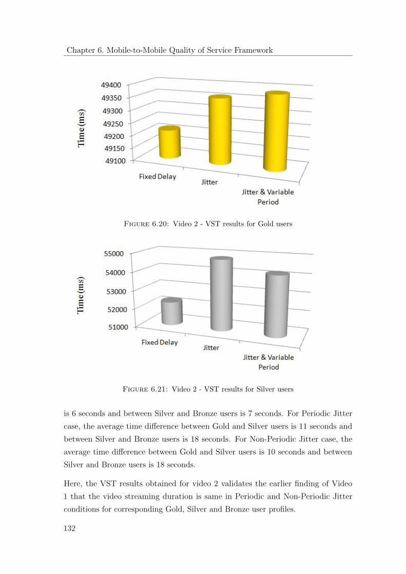
Chapter 6. Mobile-to-Mobile Quality of Service Framework
Figure 6.20: Video 2 - VST results for Gold users
Figure 6.21: Video 2 - VST results for Silver users
is 6 seconds and between Silver and Bronze users is 7 seconds. For Periodic Jitter
case, the average time difference between Gold and Silver users is 11 seconds and
between Silver and Bronze users is 18 seconds. For Non-Periodic Jitter case, the
average time difference between Gold and Silver users is 10 seconds and between
Silver and Bronze users is 18 seconds.
Here, the VST results obtained for video 2 validates the earlier finding of Video
1 that the video streaming duration is same in Periodic and Non-Periodic Jitter
conditions for corresponding Gold, Silver and Bronze user profiles.
132
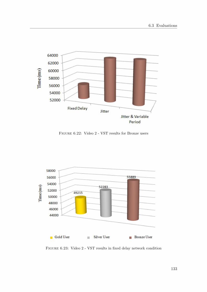
6.3 Evaluations
Figure 6.22: Video 2 - VST results for Bronze users
Figure 6.23: Video 2 - VST results in fixed delay network condition
133
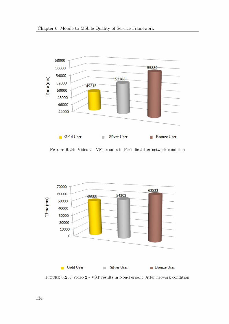
Chapter 6. Mobile-to-Mobile Quality of Service Framework
Figure 6.24: Video 2 - VST results in Periodic Jitter network condition
Figure 6.25: Video 2 - VST results in Non-Periodic Jitter network condition
134
6.3 Evaluations
6.3.5 VST Mathematical Modeling
Similar to file sharing applications, the evaluation of video streaming application is
presented in two different modes:
VST Comparison: VST evaluations for two different files in order to study the
comparison of VST behavior for three different user profiles for a given network
condition.
VST Behavior: VST evaluations for two different files in order to study the VST
behavior of each individual user profile based on the given network condition i.e.,
Fixed packet delay, Periodic Jitter and Non-Periodic Jitter.
In the subsection below, the mathematical models are presented for two different
modes of VST evaluation. The overall objective is to validate the obtained experi-
mental results in the above section and to propose a sophisticated mathematical
tool that may help the network operators to study the VST behavior for different
network settings and for various user profiles.
6.3.5.1 VST Comparison Based on User Profiles
Let us assume the Gold user profile as a reference model for our VST evaluations
i.e., no network delay and network variations for a given VST session. The rest of
the user profile models (such as Silver and Bronze profiles) can be easily derived
with respect to the reference model. In the simulation setup used as a testbed for
underlying network, the same network settings are modeled for Fixed packet delay
case as presented in File sharing application in section 6.4.1:
Hence, for a given VST reference model the VST(S) for Silver user profile can be
derived as:
V ST (S) = V ST (G) + DLi + DL(S) ∗Ni + DSi + Ds ∗Ni + V net
where, V ST (G) is VST computed for Gold user profile,
DLi is the initial delay induced in the network,
DL(S) is the fixed interval delay,
DSi is the software delay induced by the initial delay generation function,
Ds is the software delay induced by the fixed delay generation function,
V net is the delay produced by the network variations or fluctuations for an ongoing
135
Chapter 6. Mobile-to-Mobile Quality of Service Framework
session,
and Ni is the number of iterations how many times a fixed delay is produced for a
complete VST span.
In the measurement experiment, the length of the initial delay is kept equal to the
fixed interval delays for simplicity i.e., DLi = DL(S) and DSi = Ds. So, simplifying
the above equation:
V ST (S) = V ST (G) + DL(S) ∗ (Ni + 1) + Ds ∗ (Ni + 1) + V net
and
V ST (S) = V ST (G) + DL(S) ∗ (Ni + 1) + Ds ∗ (Ni + 1) (6.6)
where, Vnet can be assumed as ’0’ if a dedicated path (with no fluctuations) is
reserved for a particular service session.
The only thing which is unknown in the above equation is the Ni. However, as we
know that the delay function is called after every 3 seconds, so the value of Ni can
be easily found with the following formula.
Ni = V ST (G) + DL(S) + Ds + V net/3000
where Ni is an integer i.e., the division sign is for integer division (non-fraction). It
is worthy to note that Ni is dependent on the network variations Vnet. That means,
even the small network variations can cause more delay cycles and more software
delays in the calculation of VST.
Hence referring to the figure 6.17, the value of VST for Silver user profile can be
calculated with the help of equation 6.6 as:
V ST (S) = V ST (G) + 150 ∗ (Ni + 1) + 50 ∗ (Ni + 1)
where V ST (G) = 63519 ms, taken from figure 6.17
DL(S) = 150 ms (according to table 6.2) ,
and Ds = 50 ms (The software delay is measured for the experimental setup explained
in section 6.3.1)
Finally, calculating Ni from the above formula:
Ni = 63519 + 150 + 50/3000 = 21
Thus, V ST (S) = 67919 ms
It is important to note that in contrast to the file sharing application, the experimental
measurement of video streaming are closer to the corresponding theoretical results.
136
6.3 Evaluations
This is an indication of less variations produced by the underlying network in
streaming case.
Equation 6.6 holds true in order to compute VST in Bronze user case, but the delay
value will be changed from 150 ms to 350 ms according to table 6.2. Hence, again
referring to figure 6.17, the VST(B) can be computed in a similar way as equation
6.6:
V ST (B) = V ST (G) + DL(B) ∗ (Ni + 1) + Ds ∗ (Ni + 1) (6.7)
V ST (B) = 63519 + 350 ∗ (Ni + 1) + 50 ∗ (Ni + 1)
where V ST (G) = 63519 ms,
DL(B) = 350 ms (according to table 6.2) ,
and Ds = 50 ms (The software delay is measured for the experimental setup explained
in section 6.3.1)
Finally, calculating Ni from the above formula:
Ni = 63519 + 350 + 50/3000 = 21
Thus, V ST (B) = 72319 ms
Equation 6.6 still holds true for computing VST in Periodic Jitter conditions, but
the delay is a random variable in this case with the possible outcome in the range
specified in the table 6.2. For Non-Periodic Jitter case, equation 6.5 is also true
with random delay variable. Moreover, Ni will also become a random variable for
Non-Periodic case because the delay interval will be randomly generated according
to the table 6.2.
6.3.5.2 VST Behavior for Different Network Conditions
For a given reference model of Gold user profile, the value of VST for Fixed packet
delay and for Periodic Jitter network condition should be ideally same since there
is no network delay and variations assumed. However, in the given experimental
setup there is a possibility of slight variation in the VST values due to software delay
variations of both fixed delay function and a random delay function. Here, one can
argue that there is no need of executing delay functions in the Gold user case. But,
on the contrary, the delay functions are still executed to produce an initial delay
of ’0’ value in the given simulation setup. Therefore, the VST relation for different
137
Chapter 6. Mobile-to-Mobile Quality of Service Framework
network settings can be derived as:
V ST (PJ) = V ST (D) + V soft Gold User Profile (6.8)
where, V ST (PJ) is the VST value in Periodic Jitter network condition,
V ST (D) is the VST value for fixed packet delay network condition
and V soft is the delay variations in executing the two software functions.
The above relationship can be validated from the experimental results shown in
figures 6.14 and 6.20. On the contrary, for Silver and Bronze user profiles the
VST(PJ) and VST(D) relationship is highly dependent on the sum of the individual
delays for a given VST session produced by the random generator function for
Periodic Jitter network condition. For instance assuming the Vsoft as ’0’ for real
network case, if the sum of individual random delays is equal to the sum of the
individual fixed delays then the value of VST (PJ) and VST (D) will be the same.
Similarly, the VST (PJ) will be greater or less than VST (D) if the sum of individual
random delays would be greater or less than the sum of the individual fixed delays.
Hence, this relationship can be mathematically modeled as:
V ST (PJ)
> V ST (D), if(
∑nx=1 DLfx >
∑nx=1 DLpjx)
< V ST (D), if(∑n
x=1 DLfx <∑n
x=1 DLpjx) Silver User Profile
= V ST (D), if(∑n
x=1 DLfx =∑n
x=1 DLpjx)
(6.9)
V ST (PJ)
> V ST (D), if(
∑nx=1 DLfx >
∑nx=1 DLpjx)
< V ST (D), if(∑n
x=1 DLfx <∑n
x=1 DLpjx) Bronze User Profile
= V ST (D), if(∑n
x=1DLfx =∑n
x=1 DLpjx)
(6.10)
138
6.4 Conclusion
6.4 Conclusion
The chapter presents the design and implementation of M2M QoS framework and
explains how it helps to control the QoS level for an ongoing end-to-end service session.
The former research of MSP [9] presents the QoS management of mobile web services
as a part of agreement evaluation process of its proposed SLA framework. For each
new service deployed in the system, a QoS handler is written by the service provider
or sub-contracted third parties, which is kept responsible to monitor QoS parameters
negotiated in the SLA agreement. In general, the proposed agreement evaluation
process conforms to the standard of the Web Services Agreement Specification
(WS-Agreement) [18] for mobile terminals. Whereas, this dissertation presents a QoS
control and management framework for M2M services that conforms to the standards
of 3GPP Policy and Charging Control (PCC) architecture used in LTE-EPC [38].
Some salient features of the proposed QoS framework are as follows:
� The HTTP digest authentication is implemented for the authorized registration
of users in the IMS network.
� The proposed QoS framework exercises control at every stage of service pro-
visioning mechanism i.e., user registration, session establishment and media
delivery phase.
� The proposed framework enables the cellular operators to employ QoS control
based on the user profiles classification. Three different user profiles (Gold,
Silver and Bronze) are created to study the behavior of file sharing and video
streaming applications for different network settings.The mathematical models
for FTT (File Transfer Time) and VST (Video Streaming Time) are developed
for each user profile under different network conditions.
It is concluded that a for a given reference model of FTT i.e., FTT(G) for instance,
the corresponding FTT models such as, FTT(S) and FTT(B) can be easily derived
based on the following equation:
FTT (S) = FTT (G) + DL(S) ∗ (Ni + 1) + Ds ∗ (Ni + 1) + V net
FTT (B) = FTT (G) + DL(B) ∗ (Ni + 1) + Ds ∗ (Ni + 1) + V net
139
Chapter 6. Mobile-to-Mobile Quality of Service Framework
Similary, VST(S) and VST(B) can be derived from the following formulation:
V ST (S) = V ST (G) + DL(S) ∗ (Ni + 1) + Ds ∗ (Ni + 1) + V net
V ST (B) = V ST (G) + DL(B) ∗ (Ni + 1) + Ds ∗ (Ni + 1) + V net
It is identified that there is a slight difference between the theoretical values computed
from the mathematical models and the corresponding experimental computed values.
However, this difference is caused by the network variations on the testbed network,
which is denoted by Vnet in the above equations.
140
Chapter 7
Conclusions
The research work is aimed to contribute in the cellular world with a new paradigm
of so-called Mobile-to-Mobile service networks. The basic idea is how mobile devices
can collaborate and disseminate information in a service-oriented fashion over the
advanced cellular data networks. In past, such kind of service networks were only
limited to local area networks, such as WiFi and bluetooth etc. However, realizing
the same concept for cellular networks is not straight forward and pose some of the
following challenges:
Quality of service and policy management In a typical Internet paradigm,
the networks are aimed to offer a best effort quality of service to their customers. In
order words, the customers will get a good quality network in the events of not much
traffic over the network. But, there are no quality of service guarantees in otherwise
situations. Thus, considering the bandwidth hungry nature of multimedia services
and bandwidth restrictions of cellular networks, the ordinary best effort policy seems
not to comply with the requirements. Therefore, a special policy control mechanism
is necessary to introduce for the provisioning of M2M service networks for cellular
networks.
Service Blocking In order to avoid OTT traffic over their networks, the cellular
operators usually block the IP access of their consumer mobile devices through the
data network. Thus, an M2M interaction is not possible without investigating and
integrating a standardized communication subsystem in this regard.
141
Chapter 7. Conclusions
Standardized Mobile Server platform The Mobile Server Platform introduced
in [9] does not conform to the standards of cellular industry and lacks the following
required features:
� It does not specify a standardized way to register itself as a client or an
application server with the cellular data network.
� It does not define the service discovery and service invocation mechanisms by
using the standardized interfaces and protocols of the cellular system.
� It does not integrate with the standardized policy and charging solution of an
operator data network.
In order to address these challenges, the dissertation contributes a Mobile Server
Platform that has the ability to register itself in the standardized application
subsystem of 4G / LTE cellular network, named as IP Multimedia Subsystem.
The introduction of IMS subsystem has enabled the cellular operators to host
applications in the LTE network, control them and apply their QoS and charging
policies accordingly.
Thus, based on the standardized communication interfaces introduced by 3GPP
for IMS and LTE-Evolved Packet Core mobile system, the M2M services like
multimedia instant messaging and real-time audio video streaming are developed for
Mobile Server Platform, which are fully compatible to work with Ericsson IMS and
Fraunhofer OpenIMS, OpenEPC testbeds. In order to address the QoS concerns,
QoS framework has been introduced in order to fulfill the requirements of 3GPP
Policy and Charging Control (PCC) mechanism. The last but not the least, the
performance evaluation of Mobile Server Platform is extensively carried out based
on the various user classifications and service types.
7.1 Limitations and Outlook
Although the research has reached its aims, this section is dedicated to discuss the
overall implications and limitations of the proposed work. Moreover, a potential
road-map for the future work is also presented in this discussion.
142
7.1 Limitations and Outlook
First, from the implementation point of view, all the implementations and testing
carried out in this work are compliant and limited to the IMS testbeds available
from Ericsson and Fraunhofer institutes running in a lab environment with limited
resources and infrastructure. Therefore, it is expected that if tested in the real
world scenario, the current implementation of Mobile Server Platform may require
some system level modifications prior to testing with the operator’s LTE and
IMS infrastructure. For instance, the proposed server platform only implements
a commonly used authorization scheme for SIP communication i.e., HTTP Digest
Access Authentication. Thus for security reasons, if an operator’s network does not
support this authentication scheme then the server platform will not be able to gain
access to the operator’s IMS network.
Next, in the proposed architecture the registration of users’ devices as mobile
application server requires a manual assignment of static IP addresses (may not be
available from network operators owing to business nodes) and Port numbers against
every individual device in the operator’s DNS system. This could be a tiresome
process for a network of several hundred devices or more. Thus, a better and more
flexible approach would be the automatic assignment of static IPs to particular user
profiles. That means, whenever a certain user is logged into the operator’s data
network, the network assigns the same IP address every time.
Furthermore, chapter 6 presents a schematic study of the file transfer and video
streaming latencies for various types and characteristics of the underlying network
i.e., fixed packet delay, periodic and non-periodic Jitter conditions etc. Whereas,
the evaluation results obtained in this regard do not reflect the real-time testings on
operator network rather are based on the software simulations of such network types
and conditions. Similarly, the corresponding mathematical models are developed in
view of such software implementations of different network behaviors.
In addition to addressing the above mentioned limitations of our work, following
improvements and extensions to the M2M service model are also recommended from
the futuristic research and development point of view:
The data center network is the backbone of every telecom network. Whereas,
the relentless growth of multimedia traffic has seriously questioned the rigorous
architecture of legacy data centers. Hence, Software-Defined Networking (SDN)
is a new networking paradigm that decouples the control plane of a data center
143
Chapter 7. Conclusions
network from its user plane and offers programmability of data plane devices to
manage and control the ongoing traffic flows and ensure application-aware quality of
service on top. Therefore, in order to enhance the dynamicity and control of the
proposed telco-oriented M2M service model, an integration with state-of-the-art
SDN networking paradigm can help in the optimization of the bursty M2M traffic.
Whereas, the load balancing feature of an SDN enabled network further secures the
ability to satisfy the different QoS requirements of M2M services by instant traffic
identification and dynamic traffic rerouting mechanisms.
144
Bibliography
[1] 3GPP. GPRS and EDGE. Web Article. URL http://www.3gpp.org/
technologies/keywords-acronyms/102-gprs-edge. [Accessed 11 December,
2014].
[2] 3GPP. IP Multimedia Subsystem. Web Article. URL http://www.3gpp.org/
technologies/keywords-acronyms/109-ims. [Accessed 11 December, 2014].
[3] 3GPP. Transparent end-to-end packet switched streaming service (PSS); 3GPP
file format (3GP). TS 26.244, 3rd Generation Partnership Project (3GPP), Dec.
2007. URL http://www.3gpp.org/ftp/Specs/html-info/26244.htm.
[4] 3GPP. General audio codec audio processing functions; Enhanced aacPlus
general audio codec; Fixed-point ANSI-C code. TS 26.411, 3rd Generation
Partnership Project (3GPP), Sept. 2007. URL http://www.3gpp.org/ftp/
Specs/html-info/26411.htm.
[5] 3GPP. Messaging service using the IP Multimedia (IM) Core Network (CN)
subsystem; Stage 3. TS 24.247, 3rd Generation Partnership Project (3GPP),
Mar. 2008. URL http://www.3gpp.org/ftp/Specs/html-info/24247.htm.
[6] 3GPP. Support of Short Message Service (SMS) over generic 3GPP In-
ternet Protocol (IP) access; Stage 2. TS 23.204, 3rd Generation Partner-
ship Project (3GPP), Sept. 2008. URL http://www.3gpp.org/ftp/Specs/
html-info/23204.htm.
[7] G. T. 3rd Generation Partnership Project. 3gpp release 8. URL http://www.
3gpp.org/specifications/releases/72-release-8.
145
BIBLIOGRAPHY
[8] I. E. a Converged World. Quality of Service (QoS) and Policy Management
in Mobile Data Networks. 915-2731-01 Rev B(915-2731-01):23, July 2011.
Validating Service Quality to Ensure Subscriber Quality of Experience (QoE).
[9] F. Aijaz. Mobile Server Platform - Architectures and Protocols for Future M2M
Ecosystems. PhD thesis, RWTH Aachen University, Germany, July 2011. URL
http://www.comnets.rwth-aachen.de.
[10] F. Aijaz, S. Ali, M. Aziz, and B. Walke. Enabling resource-oriented mobile
web server for short-lived services. In Communications (MICC), 2009 IEEE
9th Malaysia International Conference on, pages 392–396, Dec 2009. doi:
10.1109/MICC.2009.5431538.
[11] F. Aijaz, S. Ali, M. Aziz, and B. Walke. Enabling high performance mobile web
services provisioning. In Vehicular Technology Conference Fall (VTC 2009-Fall),
2009 IEEE 70th, pages 1–6, Sept 2009. doi: 10.1109/VETECF.2009.5378949.
[12] F. Aijaz, S. Ali, M. Aziz, and B. Walke. The resource-oriented mobile web
server for long-lived services. In Wireless and Mobile Computing, Networking
and Communications (WiMob), 2010 IEEE 6th International Conference on,
pages 71–77, Oct 2010. doi: 10.1109/WIMOB.2010.5644858.
[13] U. Akram. Quality of Service Evaluation of IP Multimedia Services based on
service differentiation over the mobile networks. Master’s thesis, Informatik 5,
RWTH Aachen University, November 2013.
[14] Alcatel-Lucent. Introduction to evolved packet core. Strategic White
Paper, (CPG2896090226 (03)):12, 2010. URL https://marcomstore.
alcatel-lucent.com/CPG2896090226_wp.pdf.
[15] I. Ali, A. Casati, K. Chowdhury, K. Nishida, E. Parsons, S. Schmid, and
R. Vaidya. Network-based mobility management in the evolved 3gpp core
network. Communications Magazine, IEEE, 47(2):58–66, February 2009. ISSN
0163-6804. doi: 10.1109/MCOM.2009.4785381.
[16] G. Americas. SAE/EPC: System Architecture Evolution/Evolved Packet Core.
Web Article. URL http://www.4gamericas.org/index.cfm?fuseaction=
page&pageid=1077. [Accessed 16 December, 2014].
146
BIBLIOGRAPHY
[17] G. Americas. The Mobile Broadband Evolution: 3GPP Release 8 and beyond
HSPA+, SAE/LTE and LTE-Advanced. White Paper, Volume 2, Issue 6:PP
37 – 44, February 2009. URL http://www.4gamericas.org/documents/3GPP_
Rel-8_Beyond_02_12_09.pdf.
[18] A. Andrieux, K. Czajkowski, A. Dan, K. Keahey, H. Ludwig, T. Nakata,
J. Pruyne, J. Rofrano, S. Tuecke, and M. Xu. Web Services Agree-
ment Specification (WS-Agreement). Technical report, Global Grid
Forum, Grid Resource Allocation Agreement Protocol (GRAAP) WG,
Sept. 2005. URL http://www.ggf.org/Public_Comment_Docs/Documents/
Oct-2005/WS-AgreementSpecificationDraft050920.pdf.
[19] M. Aziz and M. Jarke. Mobile-to-Mobile Multimedia Service Provisioning in the
IMS Using REST-Based Mobile Services. International Journal of Computer and
Communication Engineering (IJCCE), (Volume 2, No 4, ISSN: 2010-3743, PP:
455-459), July 2013. URL http://www.ijcce.org/papers/226-W0005.pdf.
[20] M. Aziz, U. Akram, S. Javaid, and M. Jarke. QoS Framework for Mobile-to-
Mobile Multimedia File Sharing Applications. Manuscript written for publica-
tion.
[21] M. Aziz, S. Javaid, and M. Jarke. Mobile-to-mobile multi-user chat service
framework for operator networks. In Multimedia Computing and Systems
(ICMCS), 2014 International Conference on, pages 979–984, April 2014. doi:
10.1109/ICMCS.2014.6911365.
[22] M. Aziz, U. Akram, K. Rashed, and M. Jarke. QoS framework for Mobile-
to-Mobile multimedia streaming applications. In Science and Information
Conference (SAI), 2015, pages 1011–1017, July 2015. doi: 10.1109/SAI.2015.
7237266.
[23] D. Balasubramanian. QoS in Cellular Networks. Washington University in
Saint Louis, May 2006. URL http://www.cse.wustl.edu/~jain/cse574-06/
cellular_qos.htm.
[24] A. Basir. Quality of Service(QoS) in LTE. 4G LTE world
blogspot, January 2013. URL http://4g-lte-world.blogspot.de/2013/01/
quality-of-service-qos-in-lte.html.
147
BIBLIOGRAPHY
[25] T. Berners-Lee, R. Fielding, and L. Masinter. Uniform Resource Identifier
(URI): Generic Syntax. RFC 3986 (INTERNET STANDARD), Jan. 2005. URL
http://www.ietf.org/rfc/rfc3986.txt. Updated by RFCs 6874, 7320.
[26] R. Braden, L. Zhang, S. Berson, S. Herzog, and S. Jamin. Resource ReSerVation
Protocol (RSVP) – Version 1 Functional Specification. RFC 2205, Internet
Engineering Task Force, Sept. 1997. URL http://www.rfc-editor.org/rfc/
rfc2205.txt.
[27] M. A. A. C. S. Patil, R. R. Karhe. Development of mobile technology: A
survey. International Journal of Advanced Research in Electrical, Electronics
and Instrumentation Engineering (IJAREEIE), (Volume 1, Issue 5, ISSN: 2278-
8875), November 2012. URL http://www.ijareeie.com/upload/november/
6_DevelopmentofMobile.pdf.
[28] G. Camarillo and M. A. Garcia-Martin. The 3G IP Multimedia Subsystem (IMS):
merging the Internet and the cellular worlds, volume ISBN 978-0-470-51662-1
(HB). John Wiley and Sons Ltd, third edition, 2008.
[29] B. Campbell, R. Mahy, and C. Jennings. The Message Session Relay Protocol
(MSRP). RFC 4975 (Proposed Standard), Sept. 2007. URL http://www.ietf.
org/rfc/rfc4975.txt.
[30] Y. Cao, M. Jarke, R. Klamma, O. Mendoza, and S. Srirama. Mobile access
to mpeg-7 based multimedia services. In Mobile Data Management: Systems,
Services and Middleware, 2009. MDM ’09. Tenth International Conference on,
pages 102–111, May 2009. doi: 10.1109/MDM.2009.21.
[31] A. Chaudry, M. Aziz, F. Aijaz, and B. Walke. Mobile-to-mobile multimedia
streaming using rest-based mobile services. In Multimedia Computing and
Systems (ICMCS), 2012 International Conference on, pages 681–686, May 2012.
doi: 10.1109/ICMCS.2012.6320232.
[32] I. S. Communications Technology. Latin America Frequencies. Web Article. URL
http://ctisacr.com/Spanish/PDF/CTISA-FREQ.pdf. [Accessed 16 December,
2014].
148
BIBLIOGRAPHY
[33] Conningtech. Networking – Something Good to Know. Conningtech
blogspot, July 2010. URL http://conningtech.blogspot.de/2010/07/
mobile-network-evolution-gprs.html.
[34] R. Copeland. Implementing LTE with IMS. Technical Report
presented by Huawei Techologies at ETSI IMS Implementation De-
ployment and Testing , Sophia Antipolis France 24/25 November
2010. URL http://docbox.etsi.org/Workshop/2010/201011_IMSWORKSHOP/
HUAWEI_Copeland_ImplementingLTEandIMS.pdf.
[35] D. Corporation. The Architecture and Benefits of IMS. White Paper, 11297-01:
12, August 2009. URL http://www.dialogic.com/~/media/products/docs/
whitepapers/11297-ims-arch-benefits-wp.pdf.
[36] D. Corporation. The Architecture and Benefits of IMS. White Paper, 11297-01:
12, August 2009. URL http://www.dialogic.com/~/media/products/docs/
whitepapers/11297-ims-arch-benefits-wp.pdf.
[37] N. S. N. Corporation. A technology guide and vision Quality of Service re-
quirements in tomorrow-s connected world. Technology guide, Nokia Siemens
Networks Corporation, May 2008.
[38] H. Ekstrom. QoS control in the 3GPP evolved packet system. Communications
Magazine, IEEE, 47(2):76–83, February 2009. ISSN 0163-6804. doi: 10.1109/
MCOM.2009.4785383.
[39] Ericsson. Ericsson diameter signaling controller. Ericsson Portfolio ex-
pansion 2013. URL http://www.ericsson.com/ourportfolio/products/
diameter-signaling-controller. [Accessed 16 December, 2014].
[40] Ericsson. Introduction to IMS. White Paper, 284 23-8123 Uen Rev A:22,
March 2007. URL http://www.facweb.iitkgp.ernet.in/~pallab/mob_com/
Ericsson_Intro_to_IMS.pdf.
[41] Ericsson. What is Voice Over LTE. Technical report, Ericsson Stockholm,
Sweden, January 2013. URL https://www.ericsson.com/mobility-report.
[42] ETSI. General Packet Radio Service, GPRS. Web Article. URL
http://www.etsi.org/technologies-clusters/technologies/mobile/
149
BIBLIOGRAPHY
gprs?highlight=YToxOntpOjA7czo0OiJncHJzIjt9. [Accessed 16 December,
2014].
[43] J. Ewert, L. Norrel, and S. Yamen. Diameter signaling controller in next-
generation signaling networks. White Paper, Review 284 23-3176 — Uen:6,
2012.
[44] V. Fajardo, J. Arkko, J. Loughney, and G. Zorn. Diameter Base Protocol. RFC
6733, Internet Engineering Task Force, Oct. 2012. URL https://tools.ietf.
org/rfc/rfc6733.txt.
[45] G. Finnie. IMS and the Future of Network Convergence. Heavy Reading,
Volume 3, No. 12, July 2005. URL http://www.heavyreading.com/details.
asp?sku_id=821&skuitem_itemid=783.
[46] J. C. Francis and M. A. El-Ata. Benchmarking Mobile Network QoS. 2014
47th Hawaii International Conference on System Sciences, 9:308b, 2003. doi:
http://doi.ieeecomputersociety.org/10.1109/HICSS.2003.1174862.
[47] J. Franks, P. Hallam-Baker, J. Hostetler, S. Lawrence, P. Leach, A. Luotonen,
and L. Stewart. HTTP Authentication: Basic and Digest Access Authentication.
RFC 2617, Internet Engineering Task Force, June 1999. URL http://www.
rfc-editor.org/rfc/rfc2617.txt.
[48] Fraunhofer. Openepc - open evolved packet core. Fraunhofer FOKUS Berlin
R&D Product, 2008. URL http://www.openepc.net/index.html.
[49] Fraunhofer. Epc demonstration enablers. Fraunhofer FOKUS Berlin R&D Prod-
uct, 2010. URL http://www.openepc.net/components/epc_demonstration_
enablers/index.html.
[50] Fraunhofer FOKUS NGNI. Fraunhofer FOKUS Berlin, Germany: OpenIMS
Core: Open Source test bed for IMS services. Fraunhofer Research Institute
Project, 2004-2008. URL http://www.openimscore.org/. OpenIMS: An Open
Source IMS testing Framework for Mobile Networks.
[51] F. Gabin, M. Kampmann, T. Lohmar, and C. Priddle. 3GPP Mobile Multimedia
Streaming Standards [Standards in a Nutshell]. Signal Processing Magazine,
IEEE, 27(6):134–138, Nov 2010. ISSN 1053-5888. doi: 10.1109/MSP.2010.
938087.
150
BIBLIOGRAPHY
[52] G. Gehlen. Mobile web services - concepts, prototype, and traffic performance
analysis. PhD thesis, RWTH Aachen University, Lehrstuhl fur Kommunikation-
snetze, Aachen, Germany, 2007.
[53] M. Handley, H. Schulzrinne, E. Schooler, and J. Rosenberg. SIP: Session
Initiation Protocol. RFC 2543, Internet Engineering Task Force, Mar. 1999.
URL http://www.rfc-editor.org/rfc/rfc2543.txt.
[54] M. Handley, V. Jacobson, and C. Perkins. SDP: Session Description Protocol.
RFC 4566, Internet Engineering Task Force, July 2006. URL http://www.
rfc-editor.org/rfc/rfc4566.txt.
[55] INRIA. RTP/RTCP and RTSP multimedia protocols for the inter-
net. Technical presentation for INRIA Rhone-Alpes-Planete project, Au-
gust 29 2001. URL https://noppa.aalto.fi/noppa/kurssi/s-38.2188/
viikkoharjoitukset/S-38_2188_streaming.pdf.
[56] C. Janssen. Over-the-Top Application (OTT). Technopedia def-
inition. URL http://www.techopedia.com/definition/29145/
over-the-top-application-ott.
[57] S. Javaid. Mobile-to-Mobile Multimedia IM in the IMS using REST-based
Mobile Web Services. Master’s thesis, Informatik 5, RWTH Aachen University,
March 2012.
[58] S. Josefsson. The Base16, Base32, and Base64 Data Encodings. RFC 4648,
IETF, October 2006.
[59] S. Karlsson and A. Lugn. Who was first? Web Article by
Centre for Business History, Stockholm and Telefonaktiebolaget LM Er-
icsson. URL http://www.ericssonhistory.com/changing-the-world/
World-leadership/Who-was-first/. [Accessed 16 December, 2014].
[60] P. Kessler. Ericsson IMS Client Platform. Ericsson Review, page 10,
2007. URL http://www.ericsson.com/ericsson/corpinfo/publications/
review/2007_02/files/03_imsc.pdf.
[61] H. Khlifi and J. Gregoire. IMS for Enterprises. Communications Magazine, IEEE,
45(7):68–75, July 2007. ISSN 0163-6804. doi: 10.1109/MCOM.2007.382663.
151
BIBLIOGRAPHY
[62] H. Khlifi and J.-C. Gregoire. IMS Application Servers: Roles, Requirements,
and Implementation Technologies. Internet Computing, IEEE, 12(3):40–51,
May 2008. ISSN 1089-7801. doi: 10.1109/MIC.2008.57.
[63] G. Kim. OTT Destroys Voice, Text Business, Isn’t Just Share Shifting. IP
Carrier blogspot, May 2012. URL http://ipcarrier.blogspot.de/2012/05/
ott-destroys-voice-text-business-isnt.html.
[64] A. Lucent. Alcatel-Lucent End-to-End 4G Long Term Evolution Solution:
Deliver the magic of 4G LTE with the leading end-to-end solution. Technical
report, Alcatel Lucent, 2011. URL http://lightspeedt.com/wp-content/
uploads/2011/06/4G_LTE_Solution_Brochure.pdf.
[65] S. Morin. Monetize your over-the-top mobile applications. TECHzine - A tech-
blog by Alcatel Lucent, September 2014. URL http://www2.alcatel-lucent.
com/techzine/monetize-over-the-top-mobile-applications/.
[66] Motorola. Cell phone development, 1973 - 1983: Making history: Developing
the portable cellular system. Web Article by Motorola Solutions. URL
http://www.motorolasolutions.com/US-EN/About/Company+Overview/
History/Explore+Motorola+Heritage/Cell+Phone+Development. [Ac-
cessed 16 December, 2014].
[67] A. Niemi, J. Arkko, and V. Torvinen. Hypertext Transfer Protocol (HTTP)
Digest Authentication Using Authentication and Key Agreement (AKA).
RFC 3310, Internet Engineering Task Force, Sept. 2002. URL http://www.
rfc-editor.org/rfc/rfc3310.txt.
[68] Nokia. Enhanced Data Rates for Global Evolution EDGE Classic and EDGE
Compact for ANSI-136 Networks. White Paper by Nokia Networks, Finland,
Nokia code: 0573-EN-0200-1.0 Libris, March 2010. URL http://tech-insider.
org/mobile/research/acrobat/000214.pdf.
[69] S. N.Srirama, M. Jarke, and W. Prinz. Mobile web service provisioning. In
AICT-ICIW 06: Proceedings of the Advanced International Conference on
Telecommunications and International Conference on Internet and Web Appli-
cations and Services, page 120. IEEE Computer Society, 2006.
152
BIBLIOGRAPHY
[70] S. Rao. Mobile Broadband Evolution - LTE and EPC. Technical Pre-
sentation by Motorola General Business at LTE EPC IEEE COMSOC,
Boston 8th April 2010. URL https://www.scribd.com/document/118101910/
Lte-Epc-Ieee-Comsoc-Rao-April-8-2010.
[71] I. Research. Top 3 drivers for migrating to IMS: IMS Services Strategies,
Product Features abd Vendor Leadership. A Survey by Infonetics Re-
search, June 2013. URL https://www.scribd.com/document/263051549/
2011-Infonetics-IMS-Service-Pro-2011-Infonetics-IMS-Service-Provider-Survey-06-22-11-vider-Survey-06-22-11.
[72] P. Research. Portio research mobile factbook 2012. Technical Report,
page 20, April 2012. URL http://www.portioresearch.com/media/1797/
MobileFactbook202012.pdf.
[73] SAFIRE. GPRS Gn Signaling Tester. Web Article by Northern Venture
Ltd (SAFIRE World). URL http://www.safire-world.com/datasheets/ds_
9241_01_gprs_gn_signaling_tester.shtm. [Accessed 11 December, 2014].
[74] H. Schulzrinne, A. Rao, and R. Lanphier. RFC 2326 - Real Time Streaming
Protocol (RTSP). Published: www.faqs.org/rfcs/rfc2326.html, April 1998.
URL www.faqs.org/rfcs/rfc2326.html.
[75] H. Schulzrinne, S. Casner, R. Frederick, and V. Jacobson. RFC3550-RTP: A
Transport Protocol for RealTime Applications. Published: www.faqs.org/
rfcs/rfc3550.html, July 2003. URL www.faqs.org/rfcs/rfc3550.html.
[76] M. P. Vij. Analysis Of 3g Uk Mobile Industry And Comparison With Vodafone
Network Based On Consumer Satisfaction Survey. IOSR Journal of Business
and Management (IOSRJBM), Volume 2, Issue 6:PP 37 – 44, July-Aug 2012.
URL www.iosrjournals.org.
[77] B. Walke and R. Briechle. A local cellular radio network for digital voice and
data transmission at 60ghz. Proceedings Cellular and Mobile Comms. Intern.,
0:215–225, Nov 1985. URL http://www.comnets.rwth-aachen.de.
[78] B. H. Walke. Mobile Radio Networks: Networking and Protocols. John Wiley
& Sons, Inc., New York, NY, USA, 2nd edition, 2001. ISBN 0471499021.
153
BIBLIOGRAPHY
[79] B. H. Walke. The roots of GPRS: the first system for mobile packet-based
global internet access. IEEE Wireless Communications, 20(5):12–23, October
2013. ISSN 1536-1284. doi: 10.1109/MWC.2013.6664469.
[80] S. Weerawarana, A. Ryman, J.-J. Moreau, and R. Chinnici. Web services descrip-
tion language (WSDL) version 2.0 part 1: Core language. W3C recommendation,
W3C, June 2007. http://www.w3.org/TR/2007/REC-wsdl20-20070626.
[81] J. Wikman and Dosa. Providing HTTP Access to Web Servers Running
on Mobile Phones, Nokia Research Centre Helsinki, May 2006. URL http:
//research.nokia.com/tr/NRC-TR-2006-005.pdf.
[82] D. Wing. Symmetric RTP / RTP Control Protocol (RTCP). RFC 4961, Internet
Engineering Task Force, July 2007. URL http://www.rfc-editor.org/rfc/
rfc4961.txt.
[83] C. Ziegler. 2G, 3G, 4G, and everything in between: an Engadget wireless primer.
Web Article, January 2011. URL http://www.engadget.com/2011/01/17/
2g-3g-4g-and-everything-in-between-an-engadget-wireless-prim/.
[Accessed 11 December, 2014].
154
List of Figures
1.1 User subscription of OTT instant messaging vs operator SMS service[63] . . . . . . . . . . . . . . . . . . . . . . . . . . . . . . . . . . . . 3
1.2 M2M smart city network concept . . . . . . . . . . . . . . . . . . . 4
2.1 Mobile network evolution from 2G/3G to LTE[70] . . . . . . . . . . 82.2 Motorola DynaTAC 8000X [66] . . . . . . . . . . . . . . . . . . . . 102.3 First GSM phone call [59] . . . . . . . . . . . . . . . . . . . . . . . . 112.4 A typical GPRS network [73] . . . . . . . . . . . . . . . . . . . . . 122.5 Protocols introduced by EDGE in GPRS [33] . . . . . . . . . . . . 142.6 LTE - Evolved Packet Core [14] . . . . . . . . . . . . . . . . . . . . 182.7 IP Multimedia Subsystem . . . . . . . . . . . . . . . . . . . . . . . . 212.8 OpenIMS and OpenEPC integration for multimedia services [48] . . 292.9 Alcatel-Lucent End-to-End 4G LTE Solution [64] . . . . . . . . . . 302.10 Huawei - Messaging using IMS over LTE [34] . . . . . . . . . . . . . . 312.11 User behaviour and wireless data relationship per month [64] . . . . 342.12 E2E QoS Function Distribution [34] . . . . . . . . . . . . . . . . . . 372.13 NSN - QoS differentiation solution and their relationships [37] . . . 39
3.1 Issues in M2M service networks . . . . . . . . . . . . . . . . . . . . 423.2 An M2M scenario depicting the Request-Response and Solicit-Response
operations [9] . . . . . . . . . . . . . . . . . . . . . . . . . . . . . . 463.3 Mobile Server Platform located on mobile device . . . . . . . . . . . 473.4 Mobile Application Server Registration to the Ericsson IMS testbed 543.5 M2M Chat application scenario . . . . . . . . . . . . . . . . . . . . 573.6 QoS Control in the LTE - Evolved Packet Core . . . . . . . . . . . 59
4.1 SIP MESSAGE Flow . . . . . . . . . . . . . . . . . . . . . . . . . . 674.2 SIP INVITE Flow . . . . . . . . . . . . . . . . . . . . . . . . . . . . 684.3 Classification of processing latencies in session establishment phase 794.4 Session establishment latencies . . . . . . . . . . . . . . . . . . . . . 804.5 File size after Base64 encoding . . . . . . . . . . . . . . . . . . . . . . 814.6 Transfer rate of image files of different sizes . . . . . . . . . . . . . . 814.7 Transfer rate of audio files of different sizes . . . . . . . . . . . . . . 824.8 Transfer rate of text files of different sizes . . . . . . . . . . . . . . . 82
5.1 QoS requirements of variuos mutlimedia application in LTE [24] . . 875.2 Call flow of M2M mutlimedia streaming service . . . . . . . . . . . 88
155
List of Figures
5.3 Implemented RTP Frame Structure [31] . . . . . . . . . . . . . . . . 945.4 Video-1 Session establishment latencies . . . . . . . . . . . . . . . . 985.5 Video-2 Session establishment latencies . . . . . . . . . . . . . . . . 985.6 Video-1 video streaming times . . . . . . . . . . . . . . . . . . . . . 995.7 Video-2 video streaming times . . . . . . . . . . . . . . . . . . . . . 100
6.1 QoS life cycle . . . . . . . . . . . . . . . . . . . . . . . . . . . . . . 1046.2 MSP Registration at the IMS level [28] . . . . . . . . . . . . . . . . 1066.3 QoS control in Session Establishment . . . . . . . . . . . . . . . . . 1126.4 File 1 - FTT results for Gold users . . . . . . . . . . . . . . . . . . 1176.5 File 1 - FTT results for Silver users . . . . . . . . . . . . . . . . . . 1186.6 File 1 - FTT results for Bronze users . . . . . . . . . . . . . . . . . 1186.7 File 1 - FTT results in fixed delay network condition . . . . . . . . 1196.8 File 1 - FTT results in Jitter network condition . . . . . . . . . . . 1196.9 File 2 - FTT results for Gold users . . . . . . . . . . . . . . . . . . 1206.10 File 2 - FTT results for Silver users . . . . . . . . . . . . . . . . . . . 1216.11 File 2 - FTT results for Bronze users . . . . . . . . . . . . . . . . . . 1216.12 File 2 - FTT results in fixed delay network condition . . . . . . . . 1226.13 File 2 - FTT results in Jitter network condition . . . . . . . . . . . 1236.14 Video 1 - VST results for Gold users . . . . . . . . . . . . . . . . . 1286.15 Video 1 - VST results for Silver users . . . . . . . . . . . . . . . . . 1296.16 Video 1 - VST results for Bronze users . . . . . . . . . . . . . . . . 1296.17 Video 1 - VST results in fixed delay network condition . . . . . . . 1306.18 Video 1 - VST results in Periodic Jitter network condition . . . . . 1306.19 Video 1 - VST results in Non-Periodic Jitter network condition . . . . 1316.20 Video 2 - VST results for Gold users . . . . . . . . . . . . . . . . . 1326.21 Video 2 - VST results for Silver users . . . . . . . . . . . . . . . . . 1326.22 Video 2 - VST results for Bronze users . . . . . . . . . . . . . . . . 1336.23 Video 2 - VST results in fixed delay network condition . . . . . . . 1336.24 Video 2 - VST results in Periodic Jitter network condition . . . . . 1346.25 Video 2 - VST results in Non-Periodic Jitter network condition . . . 134
7.1 Mobile Service Platform - Contacts list Interface . . . . . . . . . . . 1627.2 Mobile Server Platform - Audio/Video Streaming Service Interface . 1637.3 Mobile Server Platform - File Sharing Service Interface . . . . . . . 1647.4 Mobile Server Platform - Text Messaging Service Interface . . . . . 1647.5 UCT Policy Control Management System - Domain Policies . . . . 1677.6 PCRF status in Web Interface . . . . . . . . . . . . . . . . . . . . . 1677.7 PCEF status in Web Interface . . . . . . . . . . . . . . . . . . . . . 168
156
List of Tables
2.1 An overview of analogue cellular mobile radio [78] . . . . . . . . . . 92.2 Top 3 drivers for migrating to IMS, statistics 2011 [71] . . . . . . . 242.3 Top drivers for Operators migrating to IMS, statistics 2013 [71] . . 242.4 Service providers playing in IMS space [45] . . . . . . . . . . . . . . 252.5 M2M streaming results over live networks [19] . . . . . . . . . . . . 332.6 E2E QoS Functions [34] . . . . . . . . . . . . . . . . . . . . . . . . 38
5.1 RTSP mapping over REST . . . . . . . . . . . . . . . . . . . . . . . 93
6.1 File Sharing Experiments . . . . . . . . . . . . . . . . . . . . . . . . 1176.2 Video streaming experiments . . . . . . . . . . . . . . . . . . . . . . 128
7.1 Terminal nodes port numbers [50] . . . . . . . . . . . . . . . . . . . 1657.2 OpenIMS Core - HSS Web Interface [50] . . . . . . . . . . . . . . . 1657.3 OpenIMS Core - Policy Framework settings . . . . . . . . . . . . . 1667.4 OpenIMS Core - HSS Web Interface . . . . . . . . . . . . . . . . . . 166
157

Abbreviations
ARP Address Resolution Protocol
AS Application Server
DNS Domain Name System
EPC Evolved Packet Core
HSS Home Subscriber Server
HTTP Hypertext Transfer Protocol
i5 IMS MSP Informatik 5 IMS Mobile Service Platform
I-CSCF Interrogative-Call Session Control Function
iFC Initial Filter Criteria
IMS IP Multimedia Subsystem
KPI Key Performance Indicator
MAS Mobile Application Server
MSRP Message Session Relay Protocol
MPLS Multiprotocol Label Switching
MWS Mobile Web Services
PCRF Policy and Charging Rules Function
PCEF Policy and Charging Enforcement Function
P-CSCF Proxy-Call Session Control Function
QoE Quality of Experience
QoS Quality of Service
RTSP Real Time Streaming Protocol
REST Representational State Transfer
RTCP Real-Time Transport Control Protocol
RTP Real-time Transport Protocol
159
List of Figures
S-CSCF Serving-Call Session Control Function
SDP Session Description Protocol
SDS Service Development Studio
SIP Session Initiation Protocol
UA User Agent
UAC User Agent Client
UI User Interface
URI Uniform Resource Identifier
URL Uniform Resource Locator
WLAN Wireless Local Area Network
160
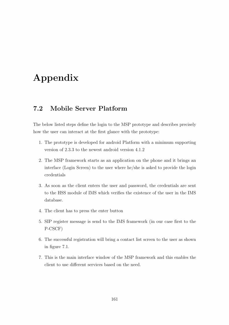
Appendix
7.2 Mobile Server Platform
The below listed steps define the login to the MSP prototype and describes precisely
how the user can interact at the first glance with the prototype:
1. The prototype is developed for android Platform with a minimum supporting
version of 2.3.3 to the newest android version 4.1.2
2. The MSP framework starts as an application on the phone and it brings an
interface (Login Screen) to the user where he/she is asked to provide the login
credentials
3. As soon as the client enters the user and password, the credentials are sent
to the HSS module of IMS which verifies the existence of the user in the IMS
database.
4. The client has to press the enter button
5. SIP register message is send to the IMS framework (in our case first to the
P-CSCF)
6. The successful registration will bring a contact list screen to the user as shown
in figure 7.1.
7. This is the main interface window of the MSP framework and this enables the
client to use different services based on the need.
161
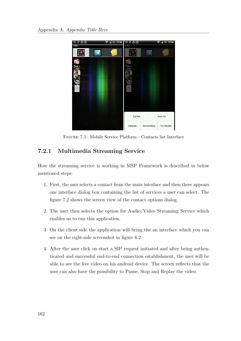
Appendix A. Appendix Title Here
Figure 7.1: Mobile Service Platform - Contacts list Interface
7.2.1 Multimedia Streaming Service
How the streaming service is working in MSP Framework is described in below
mentioned steps:
1. First, the user selects a contact from the main interface and then there appears
one interface dialog box containing the list of services a user can select. The
figure 7.2 shows the screen view of the contact options dialog.
2. The user then selects the option for Audio/Video Streaming Service which
enables us to run this application.
3. On the client side the application will bring the an interface which you can
see on the right-side screenshot in figure 6.2
4. After the user click on start a SIP request initiated and after being authen-
ticated and successful end-to-end connection establishment, the user will be
able to see the live video on his android device. The screen reflects that the
user can also have the possibility to Pause, Stop and Replay the video.
162
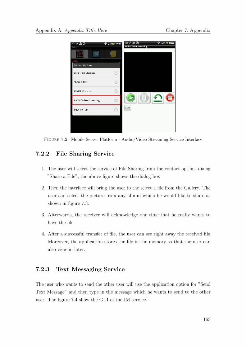
Appendix A. Appendix Title Here Chapter 7. Appendix
Figure 7.2: Mobile Server Platform - Audio/Video Streaming Service Interface
7.2.2 File Sharing Service
1. The user will select the service of File Sharing from the contact options dialog
”Share a File”, the above figure shows the dialog box
2. Then the interface will bring the user to the select a file from the Gallery. The
user can select the picture from any album which he would like to share as
shown in figure 7.3.
3. Afterwards, the receiver will acknowledge one time that he really wants to
have the file.
4. After a successful transfer of file, the user can see right away the received file.
Moreover, the application stores the file in the memory so that the user can
also view in later.
7.2.3 Text Messaging Service
The user who wants to send the other user will use the application option for ”Send
Text Message” and then type in the message which he wants to send to the other
user. The figure 7.4 show the GUI of the IM service.
163
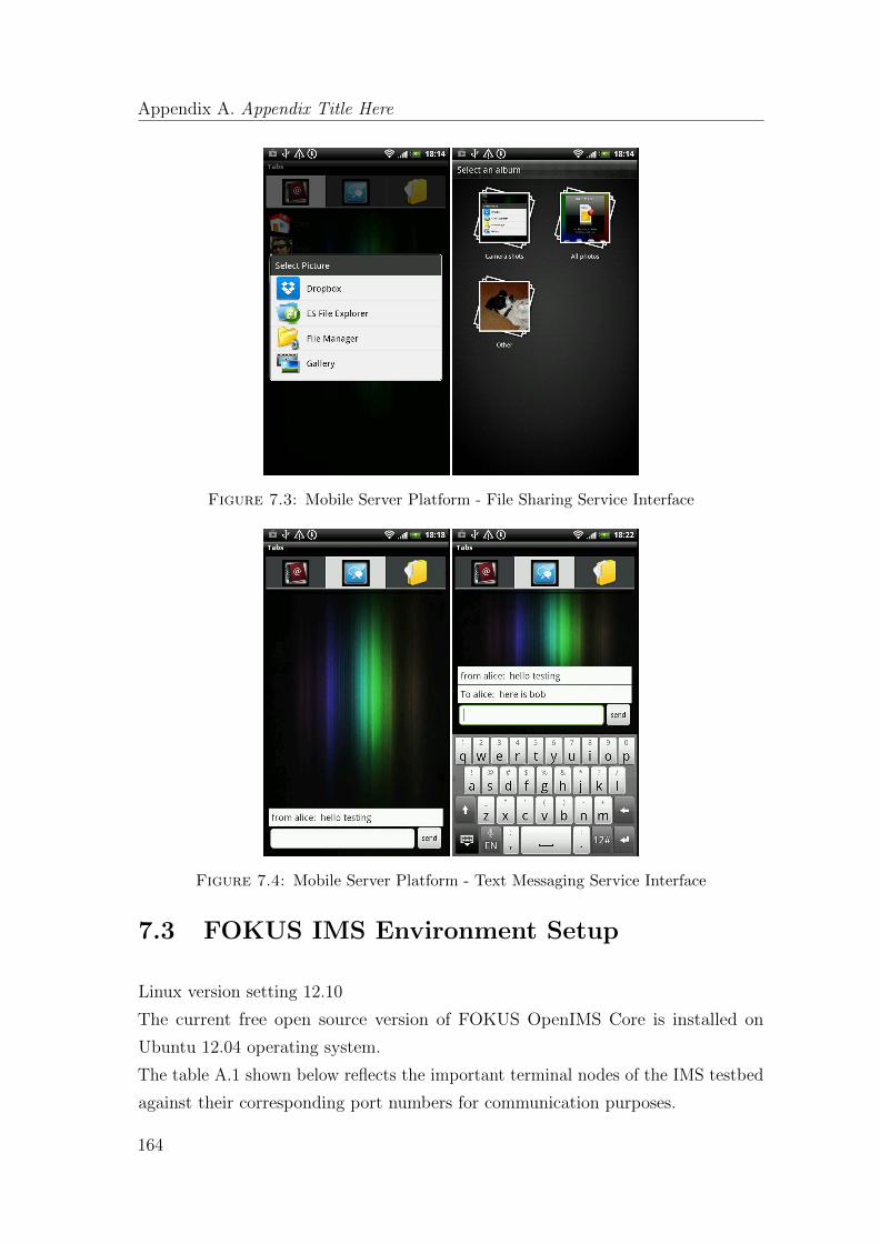
Appendix A. Appendix Title Here
Figure 7.3: Mobile Server Platform - File Sharing Service Interface
Figure 7.4: Mobile Server Platform - Text Messaging Service Interface
7.3 FOKUS IMS Environment Setup
Linux version setting 12.10
The current free open source version of FOKUS OpenIMS Core is installed on
Ubuntu 12.04 operating system.
The table A.1 shown below reflects the important terminal nodes of the IMS testbed
against their corresponding port numbers for communication purposes.
164

Appendix A. Appendix Title Here Chapter 7. Appendix
Element Port NumberP-CSCF 4060I-CSCF 5060S-CSCF 6060Diameter 3868, 3869, 3870
Table 7.1: Terminal nodes port numbers [50]
7.4 HSS Configuration [Specific Settings done for
FOKUS OpenIMS Core]
The Web Interface of OpenIMS Core lists all the operational and management
functionalities including the creation of new User, Application Server, Filter Criteria
and Trigger point. The table A.2 illustrates the web interface address along with
the credentials.
To access the OpenIMS Core Web Interface, use ”http://localhost:8080”Username: hssAdminPassword: hss
Table 7.2: OpenIMS Core - HSS Web Interface [50]
7.5 The PCRF Terminal Setup
For the Policy management in our thesis work we have also performed some config-
uration to run the PCRF terminal. The table A.3 below shows some of the very
important changes of UCT IMS Policy framework required by the testbed in order
to support QoS for a particular user. All these changes are done in ’pcscf.qos.cfg’ file
7.6 PCRF Web Interface Setup
The Web Interface is used in order to review and manage the user policies and
codecs information which enable the user permission to the demanded QoS. With the
intention of accessing the PCRF web interface first the PCRF and PCEF terminal
165
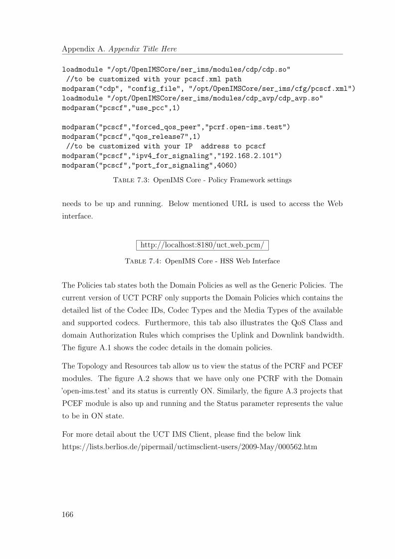
Appendix A. Appendix Title Here
loadmodule "/opt/OpenIMSCore/ser_ims/modules/cdp/cdp.so"
//to be customized with your pcscf.xml path
modparam("cdp", "config_file", "/opt/OpenIMSCore/ser_ims/cfg/pcscf.xml")
loadmodule "/opt/OpenIMSCore/ser_ims/modules/cdp_avp/cdp_avp.so"
modparam("pcscf","use_pcc",1)
modparam("pcscf","forced_qos_peer","pcrf.open-ims.test")
modparam("pcscf","qos_release7",1)
//to be customized with your IP address to pcscf
modparam("pcscf","ipv4_for_signaling","192.168.2.101")
modparam("pcscf","port_for_signaling",4060)
Table 7.3: OpenIMS Core - Policy Framework settings
needs to be up and running. Below mentioned URL is used to access the Web
interface.
http://localhost:8180/uct web pcm/
Table 7.4: OpenIMS Core - HSS Web Interface
The Policies tab states both the Domain Policies as well as the Generic Policies. The
current version of UCT PCRF only supports the Domain Policies which contains the
detailed list of the Codec IDs, Codec Types and the Media Types of the available
and supported codecs. Furthermore, this tab also illustrates the QoS Class and
domain Authorization Rules which comprises the Uplink and Downlink bandwidth.
The figure A.1 shows the codec details in the domain policies.
The Topology and Resources tab allow us to view the status of the PCRF and PCEF
modules. The figure A.2 shows that we have only one PCRF with the Domain
’open-ims.test’ and its status is currently ON. Similarly, the figure A.3 projects that
PCEF module is also up and running and the Status parameter represents the value
to be in ON state.
For more detail about the UCT IMS Client, please find the below link
https://lists.berlios.de/pipermail/uctimsclient-users/2009-May/000562.htm
166
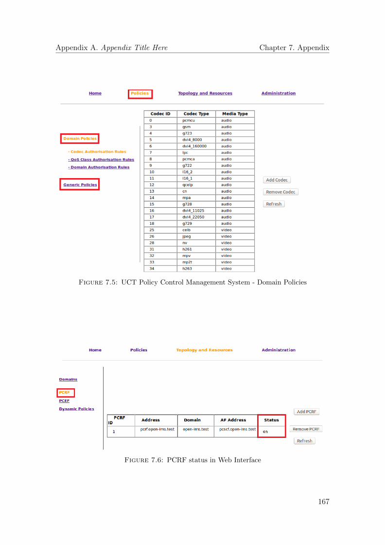
Appendix A. Appendix Title Here Chapter 7. Appendix
Figure 7.5: UCT Policy Control Management System - Domain Policies
Figure 7.6: PCRF status in Web Interface
167
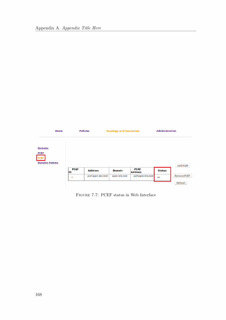
Appendix A. Appendix Title Here
Figure 7.7: PCEF status in Web Interface
168