Embed Size (px)
Citation preview

www.tjprc.org SCOPUS Indexed Journal [email protected]
ABSTRACT
This study investigated the effect of geometrical parameters on the ability of a storage to maintain the stratification by
preventing distortion of thermocline during charging and discharging cycles.
Existing methods and empirical relations have been applied to design a chilled water storage tank for a hypothetical
case of emergency cooling requirement of a data science center for 12 minutes. The effect of diffuser diameter, inlet
height and Reynolds number have been studied. The idea of using perforated dampers to damp the turbulence occurring
at high Reynolds number is introduced and empirical relations for the dampers are suggested. The validation of storage
tank design with perforated dampers is carried out at various mass flow rates in the range of Reynolds number 792 to
6072 for storage tank of different diameters.
KEYWORDS: Thermal Energy Storage, Stratification, Diffusers, Charge-Discharge Cycle, Thermocline & Perforated
Plates
International Journal of Mechanical and Production
Engineering Research and Development (IJMPERD)
ISSN(P): 2249–6890; ISSN(E): 2249–8001
Vol. 10, Issue 3, Jun 2020, 11285–11300
© TJPRC Pvt. Ltd.
IMPROVING THERMAL PERFORMANCE OF CHILLED WATER STORAGE TANK-
A NUMERICAL STUDY
SWATI PATHADE & R. S. MAURYA
Department of Mechanical Engineering, Sardar Patel College of Engineering, Maharashtra, India
Received: Jun 08, 2020; Accepted: Jun 28, 2020; Published: Sep 05, 2020; Paper Id.: IJMPERDJUN20201080
1. INTRODUCTION
Due to increased average global temperature during daytime building cooling load consumes major part of total
energy consumption. Peak of demands occurs in the daytime which can be met either by constructing bigger plant or
borrowing from neighboring utilities to compensate shortage. These solutions require high capital cost and long
duration for carrying out construction. Using chilled water storage is a low cost and effective solution to meet the
peak energy demand for short duration intensive applications. This system simply transfers peak electric loads from
on-peak period to off-peak period. It works on the principle of thermal stratification and thermocline. In a naturally
stratified storage tank, chilled and warm water are stored together in one tank without using any physical separator.
Stratification consists of three zones viz. chilled water zone resides in the tank bottom due to higher density, warm
water zone resides in the tank top due to lower density and the interfacial zone stays between them to prevent the
mixing between the chilled and warm water. This zone is called the thermocline or temperature gradient. The key
attribute of effective sensible storage is effective thermal separation, i.e., prevention of thermal mixing of warm and
cool storage medium. Thus, as long as the separation or thermocline is maintained, we can say that the thermal
storage tank is working satisfactorily. Figure1 shows the flow path diagram of fluid to/from the storage tank. During
charging (off peak period), tank receives chilled water at the bottom port through the chillers and thermocline moves
up by supplying warm water to the chillers. During discharging (in case power failure or other requirements) chilled
water moves to load centers from bottom port and water (warm) from loads comes back to the storage tank causing
thermocline to move down. During charging and discharging both, the thermocline should not get disturbed due the
turbulence caused by entry and exit of the water. To maintain a good thermal stratification, the diffusers are used
which helps to reduce turbulent mixing.
Orig
inal A
rticle

Impact Factor (JCC): 8.8746 SCOPUS Indexed Journal NAAS Rating: 3.11
11286 Swati Pathade & R. S. Maurya
Figure 1: Charge and Discharge Cycle.
Chilled water storage system has been extensively investigated by several researchers to make more efficient. The
geometry of storage system is an important parameter. A simulation of the temperature gradient existing across
thermocline at different L/D for discharging cycle was investigated by Tipasriet al. (2019) [1]. The L/D ratios of the tank
were varied as 0.7, 0.8, 1.1, 1.2, 1.4, 1.6 and 2.0 with a constant of volume of 1,755 m3. They concluded that the H/D = 2.0
gave highest remaining cold water. Nelson et al. (1999) [2] investigated a cylindrical storage system to estimate the effect
of the aspect ratio (L/D) on its performance. They concluded that aspect ratio beyond 3 doesn't have any significant effect
on the thermal performance of storage system.Hassan (2018) [3] studied various types of inlet diffusers, an elbow, two-
ring linear and radial circular diffusers. The results obtained suggested that the two-ring linear circular diffuser
produced better stratification than other two diffusers for various flow rates. Karim. (2011) [4] has experimentally
investigated that the formation of thermocline can be ensured by designing the diffuser with Froude number equal to 1 and
equal pressure drop. Lower Froude number causes unequal pressure drop and unequal flow from different openings.
Froude number is defined as the ratio of the inertia force to the buoyancy force acting on fluid. Musser et al. (2001) [5]
defined that for radial diffuser,hi is the width between the plate of radial diffuser and spreading surface. For lower diffuser,
spreading surface is tank floor and for upper diffuser, it is water free surface. Froude number is used to calculate inlet
diffuser height whereas Reynolds number is used to determine whether the flow is laminar or turbulent.
Re = q
v
Where q is the flow rate for unit diffuser length, and ν is kinematic viscosity of working water. As per Dorgan
and Elleson (1993) [6], unlike Froude number criteria the Reynolds number criteria is controversial.Bahnfleth and
Musser (1998) [7] have investigated that for very short tanks, recommended design values of Reiis near about 200 and for
large tanks having depth greater than 40 ft. (12.2 m) is about 2000. However, some report suggests that all tanks with
Reynolds number on the order of 10,000 stratify well and experience good performance of diffuser.
Improving Thermal Performance of Chilled Water Storage Tank-A Numerical Study 11287
www.tjprc.org SCOPUS Indexed Journal [email protected]
2. PROBLEMDESCRIPTION
The problem is associated to a chilled water storage tank which is designed to meet the emergency cooling load of 40TR of
a data science center. The storage tank is expected to meet the cooling load requirement for about 12 minutes as per the
standard chiller restart time after power outage M.Lin. et.al. (2015) [8]. The tank is cylindrical with diameter of 1m and
completely insulated to prevent any heat loss. It receives chilled water and hot water at 4C and 17C respectively through
a 2-inch duct. Radial diffuser is used for entry and exit of hot and cold fluid. The diffuser is designed at inlet Froude
Number (Fr)equal to 1 and Reynolds number (Rei) equal to 1056 in order to prevent destruction of thermocline during
charging and discharging. ASHRAE guidelines recommend that the Reynolds number of such system should be around
200. So, during the operation of such chilled water thermal storage tank, there is a probability of destruction of thermocline
due to high Reynolds number. Therefore, system needs certain internal geometrical modification at the exit of diffuser so
that the thermocline is saved from its destruction. It is a challenging task which needs deeper investigation to develop a
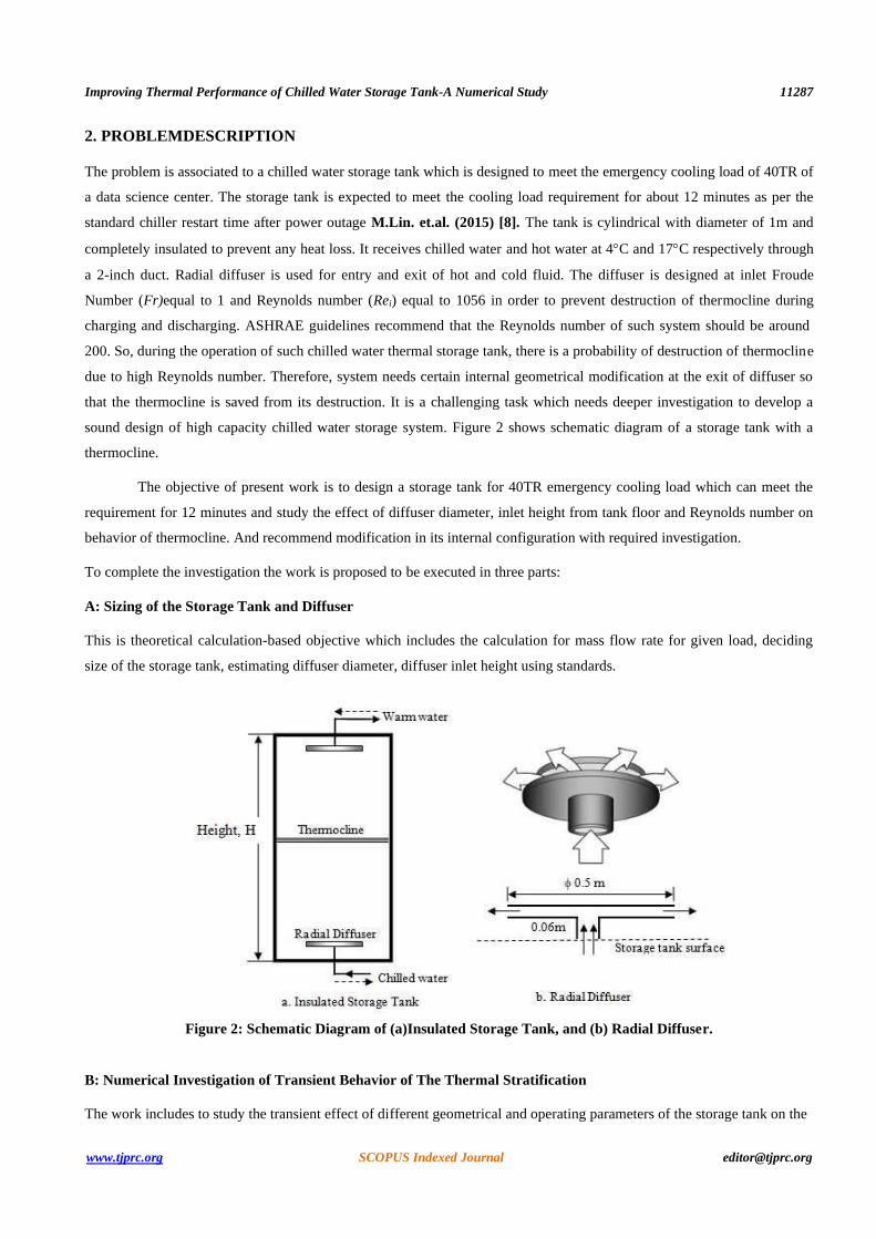
sound design of high capacity chilled water storage system. Figure 2 shows schematic diagram of a storage tank with a
thermocline.
The objective of present work is to design a storage tank for 40TR emergency cooling load which can meet the
requirement for 12 minutes and study the effect of diffuser diameter, inlet height from tank floor and Reynolds number on
behavior of thermocline. And recommend modification in its internal configuration with required investigation.
To complete the investigation the work is proposed to be executed in three parts:
A: Sizing of the Storage Tank and Diffuser
This is theoretical calculation-based objective which includes the calculation for mass flow rate for given load, deciding
size of the storage tank, estimating diffuser diameter, diffuser inlet height using standards.
Figure 2: Schematic Diagram of (a)Insulated Storage Tank, and (b) Radial Diffuser.
B: Numerical Investigation of Transient Behavior of The Thermal Stratification
The work includes to study the transient effect of different geometrical and operating parameters of the storage tank on the

11288 Swati Pathade & R. S. Maurya
Impact Factor (JCC): 8.8746 SCOPUS Indexed Journal NAAS Rating: 3.11
thermocline.
C: Investigating the Effect of Flow Damper Located Near Radial Diffuser on The Performance of Thermocline and
Flow Structure Evolving Inside the Tank.
The performance of thermocline with damper is investigated in this section.
The numerical method has been used for investigation by using a commercial software ‘ANSYS Fluent’.
3. THEORETICAL ANALYSIS
A. Sizing of the Storage Tank and Diffuser
In order to meet the cooling load requirement of 40TR for 12 minutes a mass flow rate ( m ) of 2.6 kg per second is
required. It is calculated by energy balance,
Cooling load = 40TR
40 TR×3.5 = ṁ×Cp× (Th –Tc) (1)
where, Th=17C andTc=4C.
The tank should store 1842 kg water with a volume requirement of about 1.9 m3.
The most convenient shape i.e. a cylindrical storage tank is selected whose final dimension is fixed by considering
20% extra volume for internal fittings and safe operations for designed conditions. The size of cylindrical storage tank
determined as diameter to be of 1m and height3m. It provides a useful storage of volume of chilled water of 2.36 m3. The
pipe for charging and discharging of the tank fixed to be of 2-inch diameter and flow rate is fixed by mass balance
equation.
The performance of the stratified storage tank depends on a number of parameters, such as- discharge mass flow
rate of chilled water (decided by loads), fluid entry / exit velocity of diffuser, tank size, diffuser radius, distance of diffuser
from tank surface etc.
B. Diffuser Design
The diffuser design is important to maintain effective thermocline for satisfactory performance. Theradial diffuser, as
shown in figure 2, consists of two circular plate with a narrow gap in between with inlet and outlet pipe at the center. Fluid
enters or exists through the peripheral openings. The velocity at the diffuser is calculated by using continuity equation and
the height of the diffuser from tanks horizontal surface is calculated by considering Froude number unity (Froude number
should never be more than 2). Table 1 shows the estimated value of different parameters as per design guidelines and
empirical relations.
Table 1: Tank and Diffuser Parameters
Parameters Value Parameters Value
Cold water temperature 4C Height of tank, H 3 m
Hot water temperature 17C Pipe size, (dia.) 0.05m
Mass flow rate 2.6 kg/s Radial diffuser diameter (d) 0.5m
Required volume 1.872 m3 Diffuser inlet height (h) 0.06m
Diameter of tank, D 1m Diffuser disk spacing (s) 0.04m
4. NUMERICAL INVESTIGATION

Improving Thermal Performance of Chilled Water Storage Tank-A Numerical Study 11289
www.tjprc.org SCOPUS Indexed Journal [email protected]
The thermal stratification in a storage tank is achieved due to density difference of hot and cold fluid and absence of fluid
momentum inside the tank. Although the thermocline separates hot and cold zone, but during charging and discharging
operation it may be severely damage due to entering or leaving fluid momentum. Froude number less than 2 and Reynolds
number less than 200 ensures satisfactory performance of the system. The diffuser should be designed such that the flow
enters or leave the tank at low velocity (with least turbulence). The development of flow parameters inside the tank can be
captured mathematically by using energy, mass and momentum balance considering steady/ transient, incompressible flow
with negligible body force.
A. Mathematical Model
Mass Balance Equation
𝜕𝑢
𝜕𝑥+
𝜕𝑣
𝜕𝑦= 0 (2)
Momentum Balance Equation
X-Momentum Equation
𝜌( ∂u
∂t +𝑢
𝜕𝑢
𝜕𝑥 + v
∂u
∂y )= 𝜌𝑔𝑥 −
∂p
∂x + 𝜇(
∂2𝑢
∂x2 + ∂2𝑢
∂y2). (3)
Y-Momentum Equation
𝜌( ∂v
∂t +𝑢
∂v
∂x + v
∂v
∂y )=𝜌𝑔y −
∂p
∂y+ 𝜇(
∂2𝑣
∂x2 + ∂2𝑣
∂y2) (4)
Energy Balance Equation
𝜌 𝐶𝑝 [∂T
∂t + (𝑉⃗ • ∇) 𝑇] = 𝑘∇2 T+ ϕ (5)
B. Boundary Conditions
There are three domain which needs boundary condition - diffuser inlet, outlet, wall. The temperature of two different fluid
zone - chilled and warm water.
The boundary conditions applicable to present investigation are as follows:
Inlet: Constant velocity
Outlet: Constant velocity (for same mass flow rate as that of inlet)
Wall: No-slip condition
Warm water temperature: 290K
Chilled water temperature:277K
5. NUMERICAL IMPLIMENTATION
A computational domain is selected for the investigation. It is a two-dimensional rectangular figure representing a vertical
section passing through the storage tank along its axis. It is filled with the chilled water at the bottom half of the tank and

11290 Swati Pathade & R. S. Maurya
Impact Factor (JCC): 8.8746 SCOPUS Indexed Journal NAAS Rating: 3.11
warm water in top half of the tank separated by a thermocline. Two diffuser- one in hot zone and other in chilled zone is a
part of the computational domain. They are of diameter 0.5 m and placed 0.06 m away from the tank bottom surface. Flow
enter and exits in radial direction through the diffuser. The domain considered is shown in fig.3(a). To understand the
effect of various geometrical parameters, different cases are studied.
In order to capture the propagation of interface and to ensure that the temperature gradient differentiated, a
sufficiently fine mesh system has been used without any boundary layer meshing. Whole computational domain is meshed
with quad elements of size 10-2 m at the face to avoid mesh quality related issues. The meshed domain is shown in figure
3(b).
(a) (b)
Figure 3: (a) Computational Domain and (b) Meshed Domain.
Numerical Models: Energy, Viscous-Laminar
Material properties: The density and dynamic viscosity of water at chilled and warn state is mentioned below.
Temperature (K) 277 290
ρ (kg/m3) 1000 998.2
µ (kg/ms) 1567×10-06 1083×10-06
Solution Method: Some of the important numerical settings are tabulated below,
Parameters Set up
Pressure velocity coupling SIMPLE algorithm
Spatial discretization for gradient Least square cell based
Spatial discretization for pressure Second order upwind
Spatial discretization for momentum and energy Second order upwind
Time step=1sec, Max iterations/Time step=20
The convergence criterion is set to be 10-3. Investigated results are analyzed in CFD post.
Hot Water, 290K
Chilled Water,
277K

Improving Thermal Performance of Chilled Water Storage Tank-A Numerical Study 11291
www.tjprc.org SCOPUS Indexed Journal [email protected]
6. RESULTS ANDDISCUSSIONS
The outcome of the work is presented under following two categories:
• Numerical Investigation of Transient Behavior of The Thermal Stratification
This is a two-dimensional numerical flow analysis of existing designs of the chilled water storage tank and an
assessment of few important parameter on the system performance.
• Modification in The Diffuser Setting for Better System Performance
This section presents the investigated report where flow dampers of different configurations has been used and an
optimum one is recommended.
6.1 Numerical Investigation of Transient Behavior of The Thermal Stratification
During charging and discharging operation, the thermal stratification inside the storage tank may get disturbed (destructed)
by several parameters. A simulation of flow through diffuser inside storage tank with thermocline located at the mid
horizontal plane, is carried out (based on theoretical sizing of the storage tank and the diffuser) to observe the flow pattern
developing inside the tank and causing damage to the stratification. Figure 4 shows velocity contour and temperature
distribution at time 105s after the charging started. It can be seen from the temperature contour that thermocline is rising up
during charging. The flow emerging out from the bottom radial diffuser rises up along the wall. This is due momentum in
the emerging liquid and the pressure gradient (due to hydrostatic effect) present in the system. Rising plume of chilled
water disturbs the thermocline (mixing of chilled and warm fluid starts) after certain time depending on thermocline
location during charging operation.
(a)Velocity Contour (b) Temperature Contour
Figure 4: Temperature and Velocity Contour at Time 105s.
As theoretical calculation for sizing of tank and diffuser doesn't ensure a good performance, so a deeper
investigation of the problem of thermocline disturbance is required. To support the completeness in the study few
parametric studies has been performed considering key diffuser's parameters.

11292 Swati Pathade & R. S. Maurya
Impact Factor (JCC): 8.8746 SCOPUS Indexed Journal NAAS Rating: 3.11
• The diffuser diameter (d);
• The inlet height (h);
• The inlet Reynolds number (Rei).
Validation of The Model
No experimental data is available to validate the present work where thermocline exist and moves with charging and
discharging. Hasan et al. [3] did an experimental work on a cylindrical storage tank being charged in presence of
thermocline. An elbow diffuser was used for charging and the temperature gradient across thermocline was measured.
Following parameters were considered for the study.
Tank diameter :0.4m
Tank Height :1.1m
Cold water temperature: 4.1C
Hot water temperature: 30C
Charging flow rate: 1.35LPM
Same case is simulated with present numerical scheme for its validation. Figure 5(a) shows
temperature contour located at the height of 30cm from bottom of the tank. Figure 5(b) shows the thermocline thickness in
terms non-dimensional temperature (Θ) and height of the tank (Z) for experiment and present work both. A closeness in the
result can be observed.
(a)
(b)
Figure 5: Validation (a) Temperature Contour, (b) Temperature Distribution Across Thermocline.
a) Effect of Diffuser Diameter on Thermocline
Keeping storage tank of the same size, the diffuser diameter is varied to 0.3m, 0.4m, 0.6m and 0.7m to assess the effect of
their size on the thermocline stability. This is done by assuming that thermocline initially exist at mid-height of the tank
and the charging operation starts. Chilled water enters and thermocline moves up. Higher momentum fluid (depending on
charging rate) is expected to take lesser time to disturb the thermocline. Figure 6(a) shows the shape of thermocline
interface after 100s of charging under different diameter of the diffuser. The maximum time for which thermocline remains
-0.1
0.1
0.3
0.5
0.7
0.9
1.1
0 0.1 0.2 0.3 0.4 0.5 0.6 0.7 0.8Z
Exp data,Hasan [3]
Present work

Improving Thermal Performance of Chilled Water Storage Tank-A Numerical Study 11293
www.tjprc.org SCOPUS Indexed Journal [email protected]
stable is shown in fig. 6(b). As diameter of diffuser increases thermocline tends to be more stable at a given charging rate.
This behavior may be attributed to the reduction in fluid momentum due nearness of storage tank wall to the diffuser exit.
So, it can be concluded that the diffuser diameter should be around 0.5 times of tank diameter for satisfactory operation.
Diffuser diameters
0.3m 0.4m 0.6m 0.7m
(a)
(b)
Figure 6: (a) Thermocline Interface Structure, (b) Effect of diff. dia. on Thermocline Stability.
b) Effect of Diffuser Height ‘Hi’ From Tank Horizontal Surface
The Froude number is an important indication to satisfactory performance of a stratified thermal storage tank. It should be
less than 2 as per recommendation in several literatures. It shows the competitive effect of the buoyancy and inertia force.
Higher value of this number causes jet formation at the downstream of inlet and results to mixing. Diffuser height 'h i'
effects Froude number. Figure 7 shows the effect of variation of 'hi' on the Froude number and corresponding time taken by
charging fluid to catching up the upward moving thermocline (disturbing the stability of the thermocline). Lower the
Froude number, better is the thermocline stability. So, diffuser height from tank's horizontal surface should not be very
small.
Time =100 s

11294 Swati Pathade & R. S. Maurya
Impact Factor (JCC): 8.8746 SCOPUS Indexed Journal NAAS Rating: 3.11
Figure7: Effect of Inlet Height on Thermocline Stability.
c) Effect of Inlet Reynolds Number on the Thermocline Stability
Inlet Reynolds number indicates the inertial effect of the fluid entering inside the storage tank during charging operation.
High Rei chilled water has high potential to damage the thermal stratification, if inertial forces are not dampened out by any
other mechanical means.
Figure 8: Effect of Reynolds Number on Thermocline Stability.
The effect of Rei on time taken by entering fluid to create the disturbance in thermocline is shown in fig. 8. Lower
Rei is favorable for better performance of TES in terms of disturbance, but a higher Re i is desirable from many other points
of view such as cost of the system, space etc.
The above cases clearly suggest that some internal modification in design of chilled water storage tank should be
made for improving the stratification for meeting the cooling requirement of 12 minutes.
6.2 Modification in the Internal Configuration of the Thermal Storage Tank
To dampen the inertia of the flow entering through the diffuser under charging operation at high Reynolds number, the
dampers can play a significant role. They break the fluid momentum, so fluid lose their power to propagate up and disturb
the thermocline. This is investigated here under different layout of the dampers. Dampers are of two perforated types-
vertical arrangement and horizontal arrangement considered, as shown in fig.9. Dampers are conveniently located to
dampen the flow emerging out of diffuser.

Improving Thermal Performance of Chilled Water Storage Tank-A Numerical Study 11295
www.tjprc.org SCOPUS Indexed Journal [email protected]
(a)
Figure 9: Perforated Dampers, (a) Vertical, (b) Horizontal.
To investigate the flow behavior emerging in presence of dampers and their impact on stratification, a
computational domain same as previous case is considered. The height of damper plates hd is taken as 1.5 times the height
of diffuser. These dampers are placed such that the flow coming out from inlet diffuser will be broken down by the
dampers. Hence instead of formation of high velocity jets, a stabilized flow fills the tank.
(a) Using Vertical Dampers
Figure 10 shows temperature distribution and thermocline behavior inside the tank during charging/discharging operation
in presence of vertical dampers - one, two, three and four. The thermocline is initially assumed to be at mid -height of the
tank. It moves up during charging and goes down while discharging. The deformation or alteration can be observed over a
period of operation- charging or discharging. It can be observed that the thermocline is moving without any debasement.
1 Damper 2 Dampers 3 Dampers 4 dampers
(b)
CH
AR
GIN
H (
30
0 S
eco
nd
s)

11296 Swati Pathade & R. S. Maurya
Impact Factor (JCC): 8.8746 SCOPUS Indexed Journal NAAS Rating: 3.11
Figure 10: Temperature and Velocity Distribution.
Figure 11 shows the variation of temperature inside thermocline during charging and discharging operation of the
thermal storage tank. At different time level the thermocline for a period of about 360s, it remains intact (free from
disturbance) without any kind of thickening. So steady movement of thermocline at different time intervals without
distortion for duration of 12 minutes during both charging and discharging cycle, indicates that the design parameters
considered above results in satisfactory performance of the chilled water storage tank.
Figure 11: Temperature Variation in Thermocline at Various Time Step.
(b) Using Horizontal Dampers
To observe the effect of damper in horizontal position, investigation is performed on the same storage tank with keeping
horizontal damper a distance 0.05m away from diffuser and charging at Rei=1056. Figure 12 shows temperature and
velocity distribution after time 180s, during charging and discharging operation. Comparing result with vertical dampers it
DIS
CH
AR
GIN
G (
30
0 S
eco
nds)

Improving Thermal Performance of Chilled Water Storage Tank-A Numerical Study 11297
www.tjprc.org SCOPUS Indexed Journal [email protected]
can be concluded that horizontal dampers are not as successful as vertical damper to preserve the thermocline.
Charging Cycle Discharging Cycle
Temperature Velocity Temperature
Figure 12: Temperature and Velocity Distribution.
Velocity
Storage tank is expected to perform differently under few parametric changes. So, assessment of few parameters
is performed here.
• Effect of charging and discharging rate (Re),
• Effect of spacing (Sd) between damper and diffuser,
• Effect of spacing between damper plates (Sp),
• Effect of tank aspect ratio (H/D) on the thermocline
a) Effect of Charging/Discharging Rate (Re) on the Thermocline
To study the effect of charging/discharging rate of storage tank on the movement of thermocline, the Re is varied from792
to 6072. Increasing Re is expected to destabilize the thermocline due to their higher momentum. The investigation is
performed with 4vertical dampers in series. The temperature contours as shown in fig. 13for charging and discharging
cycle, imply that the stratification is maintained without any debasement of the thermocline till Reynolds number5808.
Only thickness of the thermocline is observed to be thickened. This shows credibility of the design for a wide range of
Reynolds number application.
Reynolds Number 792 1320 5544 5808 6072
Ch
arg
ing

11298 Swati Pathade & R. S. Maurya
Impact Factor (JCC): 8.8746 SCOPUS Indexed Journal NAAS Rating: 3.11
Figure 13: Effect of Re on Thermocline.
b) Effect of Spacing (Sd) Between Damper and Diffuser
Figure 14 shows the effect of changing space between diffuser and first damper on the thermocline formed between warm
and chilled water at constant rate of charging. No significant effect on thermocline for different value of Sd equal to 1cm,
2cm, 3cm and 4cm, is observed. So, it can be concluded that spacing in-between diffuser and damper is not important.
Distance (Sd) 0.01 m 0.02m 0.03 m 0.04m
Figure 14: Effect of Space between Diffuser and Damper on Thermocline.
c) Effect of Spacing (Sp) Between Damper Plates
Dampers (perforated walls) helps to breakdown the momentum of flow emerging from periphery of radial diffuser and
passing through the damper. A better streamlined of the flow can be expected for a greater number of dampers.Figure 15
shows the effect of spacing between 4 vertical dampers with spacing (Sp) in-between as - 1cm, 2cm and 3cm. No
significant change in thermocline is observed. So, a designer may select any value as per the other parameters.
Sp: 0.01 m 0.02m 0.03 m
Figure 15: Effect of Spacing (Sp) between Damper Plates on Thermocline.
Dis
cha
rgin
g

Improving Thermal Performance of Chilled Water Storage Tank-A Numerical Study 11299
www.tjprc.org SCOPUS Indexed Journal [email protected]
d) Effect of Tank Aspect Ratio (H/D) on the Thermocline
Varying the aspect ratio (H/D) of the storage tank by keeping height (H) constant helps to store more stratified water and
ensure to serve a designated load for the longer period. The case simulated by maintaining same D/d ratio. Figure 16 shows
the effect of all these changes on the stability of thermocline with 4 dampers during charging operation at 1056 Reynolds
number. Different location of thermocline can be observed which is due to changed size of the storage tank. Thermocline
appears to be almost unaffected by the said parameter. So, it can be recommended that a designer change the capacity of
the storage tank provided it maintains all other parameters.
H/D = 3.0 H/D = 1.5 H/D = 1.0
Figure 16: Effect of Changing Aspect ratio (H/D) of the Storage Tank on Thermocline.
7. CONCLUSIONS
Present work investigates the characteristics of thermocline during charging and discharging operation of a chilled water
thermal storage tank which designed to take care of 20% of designed load of 200TR for a period of 12 minutes. Study
includes theoretical calculation for the sizing of the tank along with numerical parametric study of key design parameters.
Further certain modification in existing design is proposed to ensure better performance of the storage tank. Main outcome
of the investigation is mentioned below:
• As diameter of diffuser increases thermocline tends to be more stable at a given charging rate.
• Diffuser height from tank's horizontal surface should be not be very small.
• Lower Rei is favorable for better performance of TES in terms of disturbance, but a higher Re i is desirable from
many other points of view such as cost of the system, space etc.
• A significant improvement in thermocline stability is observed if dampers are used. Vertical dampers are more

11300 Swati Pathade & R. S. Maurya
Impact Factor (JCC): 8.8746 SCOPUS Indexed Journal NAAS Rating: 3.11
effective compared to the horizontal diffusers.
• Lower charging / discharging rate (Re) is more favorable for thermocline stability if vertical dampers are used.
REFERENCES
1. W. Tipasri, T. Wongwuttanasatian. (2019). Effect of height to diameter ratio of chilled water storage tank on temperature
gradient during discharging. EnergyProcedia, 156,254-258
2. J.E.B. Nelson, A.R. Balakrishnan, S. Srinivasa Murthy (1999). Experiments on stratified chilled-water tanks, International
Journal of Refrigeration, 22,216-234
3. Firas M. Hasan, MaatheAbdulwahedTheeb (2018). Experimental and numerical study of neat transfer process of chilled water
storage tank. Universal Journal of Mechanical Engineering,6,63-75
4. M.A.Karim. (2011). Experimental investigation of a stratified chilled-water thermal storage system. Applied Thermal
Engineering,31,1853-1860
5. A. Musser & W. P. Bahnfleth. (2001). Parametric Study of Charging Inlet Diffuser Performance in StratifiedWater Storage
Tanks with Radial Diffusers: Part 2–Dimensional Analysis, Parametric Simulations and Simplified ModelDevelopment,
HVAC&R Research, 7:2, 205-222
6. C. E. Dorgan and J. S. Elleson. (1993). Design guide for cool thermal storage: ASHRAE Atlanta.
7. W.P. Bahnfleth, A. Musser. (1998). Thermalperformance of a full-scale stratified chilled-water thermalstorage tank.ASHRAE
transaction,104,377-388
8. M. Lin, S. Shao, X. Zhang, J.Vangilder, V. Avelar, X. Hu. (2015). Strategies for data center temperature control during a
cooling system outage. Energy and Buildings,83,484-493