Embed Size (px)
Citation preview

European Union
European RegionalDevelopment FundInvesting in your future
666666666666666666666666666666666666666666666666666666666666666666666666666666666666666666666666666666666666666666666666666666666666666666666666666666666666666666666666666666666666666666666666666666666666666666666666666666666666666666666666666666666666 LOW CARBON DOMESTIC RETROFIT
Mark Elton and David TurrentEDITION 1, September 2011
improving the building fabric
building opportunitiesfor business
improving the building fabric
2
6.1 Introduction . . . . . . . . . . . . . . . . . . . . . . . . . . . . . . . .3
6.2 Understanding how thermal insulation works . . . . . . . . . .4
6.3 Common barriers and constraints for thermal upgrades . .4
6.4 Thermalbridginginretrofit . . . . . . . . . . . . . . . . . . . . . .6
6.5 Reducingairleakageinretrofit . . . . . . . . . . . . . . . . . . .7
6.6 Controllingbuildingfabricmoistureinretrofit . . . . . . . . .8
6.7 Floor insulation . . . . . . . . . . . . . . . . . . . . . . . . . . . . . .9
6.8 Cavity wall insulation . . . . . . . . . . . . . . . . . . . . . . . . .11
6.9 External wall insulation . . . . . . . . . . . . . . . . . . . . . . . .12
6.10 Internal wall insulation . . . . . . . . . . . . . . . . . . . . . . . .13
6.11 Loft (ceiling) insulation . . . . . . . . . . . . . . . . . . . . . . . .15
6.12 Pitched roof insulation . . . . . . . . . . . . . . . . . . . . . . . .16
6.13 Flat roof insulation . . . . . . . . . . . . . . . . . . . . . . . . . . .17
6.14 Windows . . . . . . . . . . . . . . . . . . . . . . . . . . . . . . . . .18
6.15 External doors . . . . . . . . . . . . . . . . . . . . . . . . . . . . .20
6.16 Fittings . . . . . . . . . . . . . . . . . . . . . . . . . . . . . . . . . .21
6.17 Summary of business opportunities . . . . . . . . . . . . . . .22
6.18 Next steps . . . . . . . . . . . . . . . . . . . . . . . . . . . . . . . .26
Disclaimer:Whileeveryefforthasbeenmadetotraceandacknowledgeallcopyrightandtrademarkholders,we would like to apologise should there be any errors or omissions.
3
building opportunities for business GUIDE 6: improving the building fabric
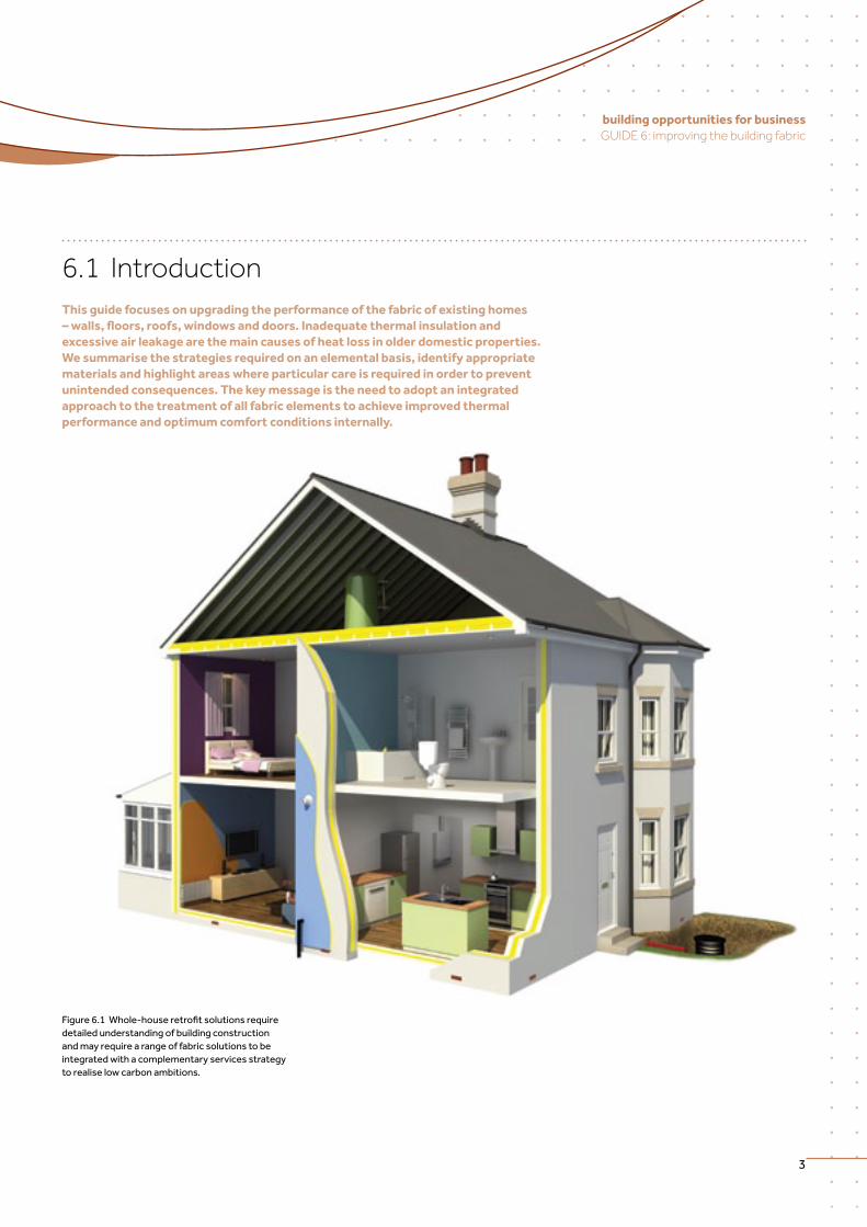
6.1 IntroductionThis guide focuses on upgrading the performance of the fabric of existing homes – walls, floors, roofs, windows and doors. Inadequate thermal insulation and excessive air leakage are the main causes of heat loss in older domestic properties. We summarise the strategies required on an elemental basis, identify appropriate materials and highlight areas where particular care is required in order to prevent unintended consequences. The key message is the need to adopt an integrated approach to the treatment of all fabric elements to achieve improved thermal performance and optimum comfort conditions internally.
Figure6.1Whole-houseretrofitsolutionsrequiredetailed understanding of building construction andmayrequirearangeoffabricsolutionstobeintegrated with a complementary services strategy to realise low carbon ambitions.
improving the building fabric
4
6.2 Understanding how thermal insulation works
There are many types of insulation, derived from natural, mineral or petrochemical sources. Thermal insulation acts as an inhibitor to heat transfer either by conduction, convection, radiation or a combination of these, reducing heat loss in winter to keep the house warm or reducing heat gain in summer to keep the house cool.
Insulation products work by trapping dry gas, such as air or a blowing agent, in lightweight,bulkybutcellularmaterialsorsometimesbyusingreflectivematerialstoreflectheatbackintothebuilding.Allareprocessedtoagreaterorlesserextenttoprovide a structure that will trap gas or air and minimise conduction. Still air is a poor conductor of heat, so bulky materials that can trap large amounts of air can reduce the ability for heat to be transferred by conduction. If a material consists of many tiny pockets of trapped air rather than a large, contiguous volume of air, the ability to transfer heat by air movement is also reduced.
Understanding that the basis of insulation is to trap either air or gas is fundamental whendesigningorinstallinginsulationintoaretrofitscheme–reducingairmovementbetween, around or across the surface of the insulation (referred to as thermal bypass) is crucial if insulation materials are to perform to their optimum.
Dependingontheconstructionofthefabric,insulationproductsareretrofittedoutside,betweenorinsidetheexistingwall,floorandroofelements.Forwalls,thesearedesignated as cavity insulation, external wall insulation (EWI) and internal wall insulation (IWI). Where they are located will depend on a number of external factors necessitating apre-installationassessmentbythespecifierortheinstaller.Formoreinformationonsurveying dwellings, see Guide 2.
6.3 Common barriers and constraints for thermal upgrades
Upgrading a building’s thermal fabric will require considered decisions to be made about the most appropriate and practical solutions. Many factors will affect the selection, such as:
• planningstatus–thepropertymaybeListedorliewithinaConservationArea,whichwill greatly restrict which fabric measures can be applied
• architecturalconsiderations–regardlessofitsplanningstatus,thepropertymayform part of a wider architectural ensemble such as a terrace where the likelihood of being able to realise planning consent for a change in appearance or ridge height is diminished
• structuralconsiderations–canthebuildingfabricsupporttheadditionalloadingsimposed by the thermal insulation systems proposed?
• occupation–willtheworkshavetobecarriedoutwithresidentslivinginthepropertyduringtheretrofitworks?
Provide planning consultancy
services to negotiate with
planning departments and
submit applications on behalf of
householders or contractors.
Business Opportunity
Provide strategic
pre-installation advice on the
selection,specificationand
detailing of insulation.
Business Opportunity
5
building opportunities for business GUIDE 6: improving the building fabric
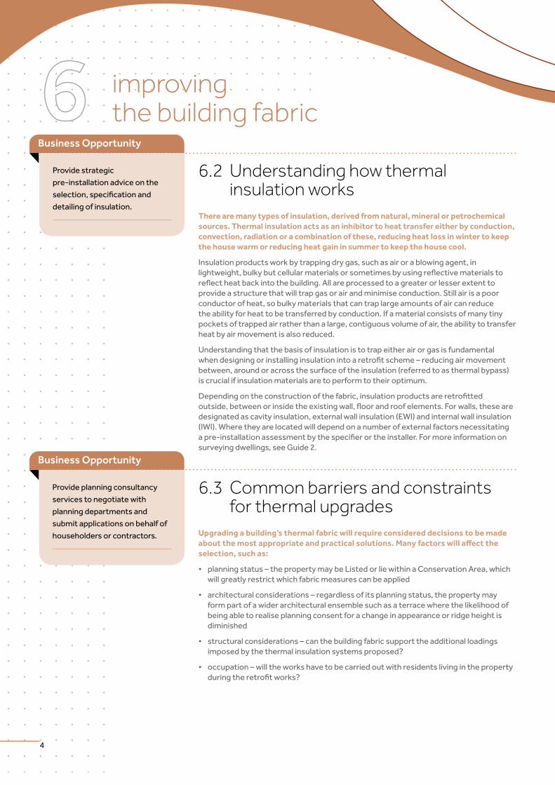
Figure6.2Installinginternalliningsandfloorinsulationisaverydisruptiveprocessanddifficulttocarryoutwithresidents living in the property. (Source: ECD Architects)
Figure6.4Insmallerrooms,canthefixturesandfittingsstillbe accommodated once IWI has been installed? (Source: ECD Architects)
• roomlayouts–canroomsstillfunctionfortheirintendedpurposeifinternalwallinsulationisadded,forexamplefittedbathrooms?
• boundaryconditions–istherephysicallysufficientaccesstoinstallexternalinsulationsystemsand maintain the original thoroughfare? Will the insulation oversail the legal boundary?
Theseandotherconsiderationswillgreatlyaffectthestrategyforretrofittingaparticularproperty–theimpactofdifferentsolutionsforeachelementwillbeexaminedmorecloselyinthefollowing sections. For further information see Guide 3.
Figure 6.3 External wall insulation has to be restrained mechanically and/or adhesively back to the wall substrate so it must be structurally sound enough to carry the additional load imposed. (Source: ECD Architects)
Figure 6.5 Narrow side access with complex external services such as this may restrict options for EWI. (Source: ECD Architects)
improving the building fabric
6
6.4 Thermal bridging in retrofitA comprehensive thermal insulation retrofit should create a continuous insulated envelope around the living accommodation and, ideally, avoid any residual thermal bridging of the structure. The extent of residual thermal bridging will vary depending on the insulation strategy selected and is generally the result of structural elements breaching the insulation zone.
Thermal bridges occur where localised building fabric elements are less well insulated than the surrounding areas and therefore allow a greater rate of heat loss. This can lead to lowered temperatures either on the internal surface or within the structure, withthesubsequentriskofcondensationandmouldgrowthaswellasthepenaltyonenergyefficiency.Whenworkingwithexistingbuildings,thetotaleliminationofthermal bridging is not always practical or even possible without extreme intervention.
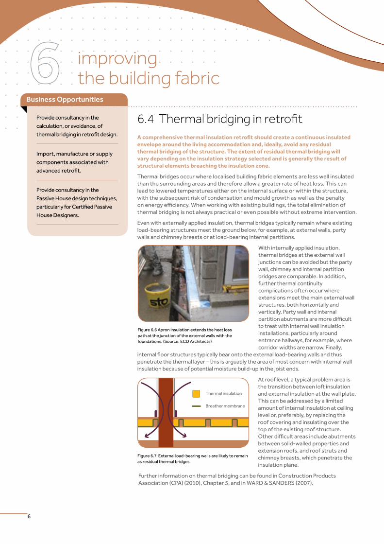
Even with externally applied insulation, thermal bridges typically remain where existing load-bearing structures meet the ground below, for example, at external walls, party walls and chimney breasts or at load-bearing internal partitions.
With internally applied insulation, thermal bridges at the external wall junctions can be avoided but the party wall, chimney and internal partition bridges are comparable. In addition, further thermal continuity complications often occur where extensions meet the main external wall structures, both horizontally and vertically. Party wall and internal partitionabutmentsaremoredifficultto treat with internal wall insulation installations, particularly around entrance hallways, for example, where corridor widths are narrow. Finally,
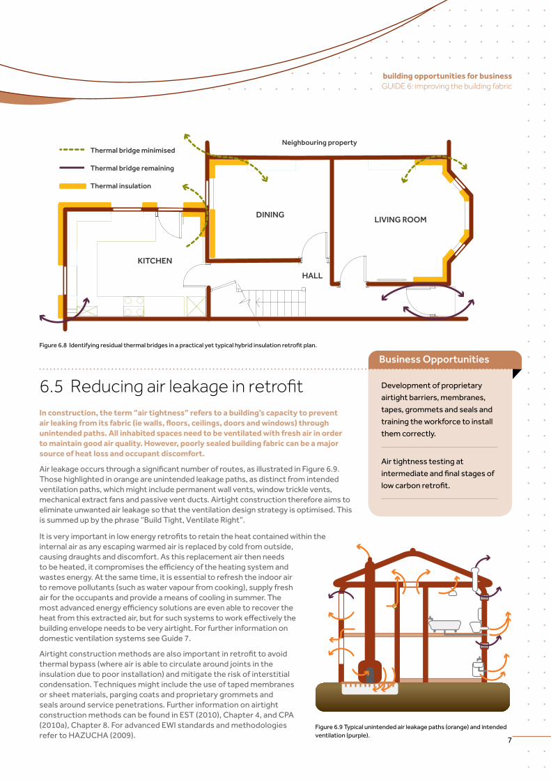
internalfloorstructurestypicallybearontotheexternalload-bearingwallsandthuspenetratethethermallayer–thisisarguablytheareaofmostconcernwithinternalwallinsulation because of potential moisture build-up in the joist ends.
At roof level, a typical problem area is the transition between loft insulation and external insulation at the wall plate. This can be addressed by a limited amount of internal insulation at ceiling level or, preferably, by replacing the roof covering and insulating over the top of the existing roof structure. Otherdifficultareasincludeabutmentsbetween solid-walled properties and extension roofs, and roof struts and chimney breasts, which penetrate the insulation plane.
Further information on thermal bridging can be found in Construction Products Association (CPA) (2010), Chapter 5, and in WARD & SANDERS (2007).
Figure 6.6 Apron insulation extends the heat loss path at the junction of the external walls with the foundations. (Source: ECD Architects)
Thermal insulation
Breather membrane
Figure 6.7 External load-bearing walls are likely to remain as residual thermal bridges.
Provide consultancy in the
calculation, or avoidance, of
thermalbridginginretrofitdesign.
Import, manufacture or supply
components associated with
advancedretrofit.
Provide consultancy in the
PassiveHousedesigntechniques,
particularlyforCertifiedPassive
House Designers.
Business Opportunities
7
building opportunities for business GUIDE 6: improving the building fabric
LIVING ROOMDINING
HALL
KITCHEN
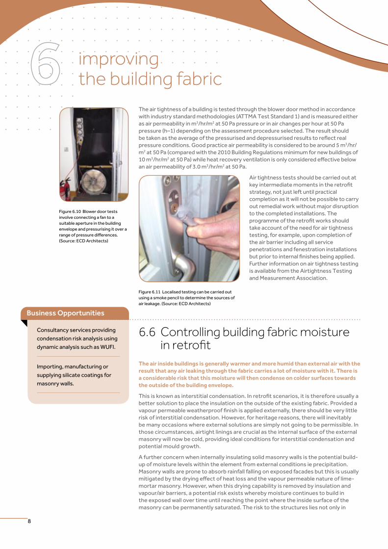
Neighbouring propertyThermal bridge minimised
Thermal bridge remaining
Thermal insulation
Development of proprietary
airtight barriers, membranes,
tapes, grommets and seals and
training the workforce to install
them correctly.
Air tightness testing at
intermediateandfinalstagesof
lowcarbonretrofit.
Figure6.8Identifyingresidualthermalbridgesinapracticalyettypicalhybridinsulationretrofitplan.
6.5 Reducing air leakage in retrofitIn construction, the term “air tightness” refers to a building’s capacity to prevent air leaking from its fabric (ie walls, floors, ceilings, doors and windows) through unintended paths. All inhabited spaces need to be ventilated with fresh air in order to maintain good air quality. However, poorly sealed building fabric can be a major source of heat loss and occupant discomfort.
Airleakageoccursthroughasignificantnumberofroutes,asillustratedinFigure6.9.Those highlighted in orange are unintended leakage paths, as distinct from intended ventilation paths, which might include permanent wall vents, window trickle vents, mechanical extract fans and passive vent ducts. Airtight construction therefore aims to eliminate unwanted air leakage so that the ventilation design strategy is optimised. This is summed up by the phrase “Build Tight, Ventilate Right”.
Itisveryimportantinlowenergyretrofitstoretaintheheatcontainedwithintheinternal air as any escaping warmed air is replaced by cold from outside, causing draughts and discomfort. As this replacement air then needs tobeheated,itcompromisestheefficiencyoftheheatingsystemandwastes energy. At the same time, it is essential to refresh the indoor air to remove pollutants (such as water vapour from cooking), supply fresh air for the occupants and provide a means of cooling in summer. The mostadvancedenergyefficiencysolutionsareevenabletorecovertheheatfromthisextractedair,butforsuchsystemstoworkeffectivelythebuilding envelope needs to be very airtight. For further information on domestic ventilation systems see Guide 7.
Airtightconstructionmethodsarealsoimportantinretrofittoavoidthermal bypass (where air is able to circulate around joints in the insulation due to poor installation) and mitigate the risk of interstitial condensation.Techniquesmightincludetheuseoftapedmembranesor sheet materials, parging coats and proprietary grommets and seals around service penetrations. Further information on airtight construction methods can be found in EST (2010), Chapter 4, and CPA (2010a), Chapter 8. For advanced EWI standards and methodologies refer to HAZUCHA (2009).
Figure 6.9 Typical unintended air leakage paths (orange) and intended ventilation (purple).
Business Opportunities
improving the building fabric
8
The air tightness of a building is tested through the blower door method in accordance with industry standard methodologies (ATTMA Test Standard 1) and is measured either as air permeability in m3/hr/m2 at 50 Pa pressure or in air changes per hour at 50 Pa pressure(h–1)dependingontheassessmentprocedureselected.Theresultshouldbetakenastheaverageofthepressurisedanddepressurisedresultstoreflectrealpressure conditions. Good practice air permeability is considered to be around 5 m3/hr/m2 at 50 Pa (compared with the 2010 Building Regulations minimum for new buildings of 10 m3/hr/m2at50Pa)whileheatrecoveryventilationisonlyconsideredeffectivebelowan air permeability of 3.0 m3/hr/m2 at 50 Pa.
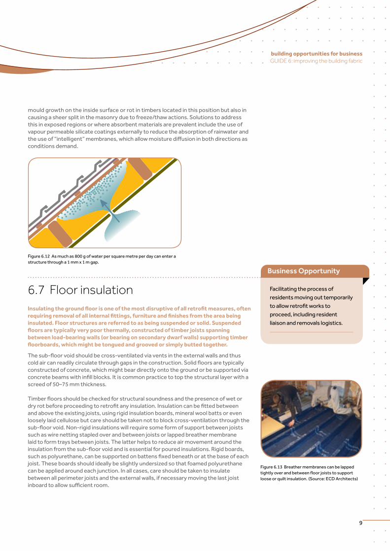
Figure 6.11 Localised testing can be carried out using a smoke pencil to determine the sources of air leakage. (Source: ECD Architects)
Air tightness tests should be carried out at keyintermediatemomentsintheretrofitstrategy, not just left until practical completion as it will not be possible to carry out remedial work without major disruption to the completed installations. The programmeoftheretrofitworksshouldtake account of the need for air tightness testing, for example, upon completion of the air barrier including all service penetrations and fenestration installations butpriortointernalfinishesbeingapplied.Further information on air tightness testing is available from the Airtightness Testing and Measurement Association.
Consultancy services providing
condensation risk analysis using
dynamic analysis such as WUFI.
Importing, manufacturing or
supplying silicate coatings for
masonry walls.
Business Opportunities
6.6 Controlling building fabric moisture in retrofit
The air inside buildings is generally warmer and more humid than external air with the result that any air leaking through the fabric carries a lot of moisture with it. There is a considerable risk that this moisture will then condense on colder surfaces towards the outside of the building envelope.
Thisisknownasinterstitialcondensation.Inretrofitscenarios,itisthereforeusuallyabetter solution to place the insulation on the outside of the existing fabric. Provided a vapourpermeableweatherprooffinishisappliedexternally,thereshouldbeverylittlerisk of interstitial condensation. However, for heritage reasons, there will inevitably be many occasions where external solutions are simply not going to be permissible. In those circumstances, airtight linings are crucial as the internal surface of the external masonry will now be cold, providing ideal conditions for interstitial condensation and potential mould growth.
A further concern when internally insulating solid masonry walls is the potential build-up of moisture levels within the element from external conditions ie precipitation. Masonry walls are prone to absorb rainfall falling on exposed facades but this is usually mitigatedbythedryingeffectofheatlossandthevapourpermeablenatureoflime-mortar masonry. However, when this drying capability is removed by insulation and vapour/air barriers, a potential risk exists whereby moisture continues to build in the exposed wall over time until reaching the point where the inside surface of the masonry can be permanently saturated. The risk to the structures lies not only in
Figure 6.10 Blower door tests involve connecting a fan to a suitable aperture in the building envelope and pressurising it over a rangeofpressuredifferences. (Source: ECD Architects)
9
building opportunities for business GUIDE 6: improving the building fabric
mould growth on the inside surface or rot in timbers located in this position but also in causing a sheer split in the masonry due to freeze/thaw actions. Solutions to address this in exposed regions or where absorbent materials are prevalent include the use of vapour permeable silicate coatings externally to reduce the absorption of rainwater and theuseof“intelligent”membranes,whichallowmoisturediffusioninbothdirectionsasconditions demand.
Figure6.12Asmuchas800gofwaterpersquaremetreperdaycanenterastructure through a 1 mm x 1 m gap.
Figure 6.13 Breather membranes can be lapped tightlyoverandbetweenfloorjoiststosupportlooseorquiltinsulation.(Source:ECDArchitects)
6.7 Floor insulation Insulating the ground floor is one of the most disruptive of all retrofit measures, often requiring removal of all internal fittings, furniture and finishes from the area being insulated. Floor structures are referred to as being suspended or solid. Suspended floors are typically very poor thermally, constructed of timber joists spanning between load-bearing walls (or bearing on secondary dwarf walls) supporting timber floorboards, which might be tongued and grooved or simply butted together.
Thesub-floorvoidshouldbecross-ventilatedviaventsintheexternalwallsandthuscoldaircanreadilycirculatethroughgapsintheconstruction.Solidfloorsaretypicallyconstructed of concrete, which might bear directly onto the ground or be supported via concretebeamswithinfillblocks.Itiscommonpracticetotopthestructurallayerwithascreedof50–75mmthickness.
Timberfloorsshouldbecheckedforstructuralsoundnessandthepresenceofwetordryrotbeforeproceedingtoretrofitanyinsulation.Insulationcanbefittedbetweenand above the existing joists, using rigid insulation boards, mineral wool batts or even loosely laid cellulose but care should be taken not to block cross-ventilation through the sub-floorvoid.Non-rigidinsulationswillrequiresomeformofsupportbetweenjoistssuch as wire netting stapled over and between joists or lapped breather membrane laid to form trays between joists. The latter helps to reduce air movement around the insulationfromthesub-floorvoidandisessentialforpouredinsulations.Rigidboards,suchaspolyurethane,canbesupportedonbattensfixedbeneathoratthebaseofeachjoist. These boards should ideally be slightly undersized so that foamed polyurethane can be applied around each junction. In all cases, care should be taken to insulate between all perimeter joists and the external walls, if necessary moving the last joist inboardtoallowsufficientroom.
Facilitating the process of
residents moving out temporarily
toallowretrofitworksto
proceed, including resident
liaison and removals logistics.
Business Opportunity
improving the building fabric
10
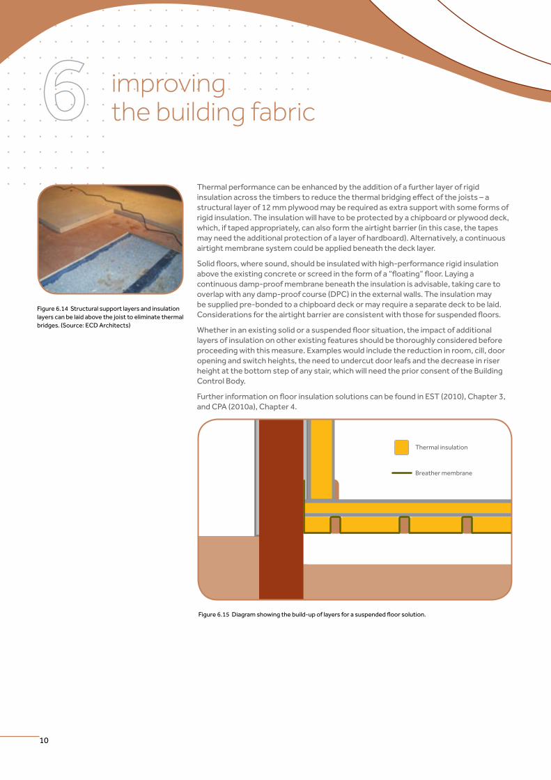
Thermal performance can be enhanced by the addition of a further layer of rigid insulationacrossthetimberstoreducethethermalbridgingeffectofthejoists–astructurallayerof12mmplywoodmayberequiredasextrasupportwithsomeformsofrigid insulation. The insulation will have to be protected by a chipboard or plywood deck, which, if taped appropriately, can also form the airtight barrier (in this case, the tapes may need the additional protection of a layer of hardboard). Alternatively, a continuous airtight membrane system could be applied beneath the deck layer.
Solidfloors,wheresound,shouldbeinsulatedwithhigh-performancerigidinsulationabovetheexistingconcreteorscreedintheformofa“floating”floor.Layingacontinuous damp-proof membrane beneath the insulation is advisable, taking care to overlap with any damp-proof course (DPC) in the external walls. The insulation may besuppliedpre-bondedtoachipboarddeckormayrequireaseparatedecktobelaid.Considerationsfortheairtightbarrierareconsistentwiththoseforsuspendedfloors.
Whetherinanexistingsolidorasuspendedfloorsituation,theimpactofadditionallayers of insulation on other existing features should be thoroughly considered before proceeding with this measure. Examples would include the reduction in room, cill, door opening and switch heights, the need to undercut door leafs and the decrease in riser height at the bottom step of any stair, which will need the prior consent of the Building Control Body.
FurtherinformationonfloorinsulationsolutionscanbefoundinEST(2010),Chapter3,and CPA (2010a), Chapter 4.
Figure 6.14 Structural support layers and insulation layers can be laid above the joist to eliminate thermal bridges. (Source: ECD Architects)
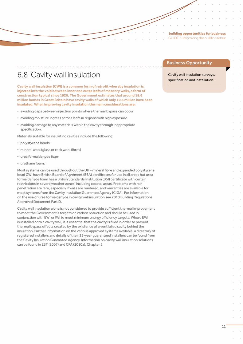
Thermal insulation
Breather membrane
Figure6.15Diagramshowingthebuild-upoflayersforasuspendedfloorsolution.
11
building opportunities for business GUIDE 6: improving the building fabric
6.8 Cavity wall insulation Cavity wall insulation (CWI) is a common form of retrofit whereby insulation is injected into the void between inner and outer leafs of masonry walls, a form of construction typical since 1920. The Government estimates that around 18.6 million homes in Great Britain have cavity walls of which only 10.3 million have been insulated. When improving cavity insulation the main considerations are:
• avoidinggapsbetweeninjectionpointswherethermalbypasscanoccur
• avoidingmoistureingressacrossleafsinregionswithhighexposure
• avoidingdamagetoanymaterialswithinthecavitythroughinappropriatespecification.
Materials suitable for insulating cavities include the following:
• polystyrenebeads
• mineralwool(glassorrockwoolfibres)
• ureaformaldehydefoam
• urethanefoam.
MostsystemscanbeusedthroughouttheUK–mineralfibreandexpandedpolystyrenebeadCWIhaveBritishBoardofAgrément(BBA)certificatesforuseinallareasbutureaformaldehydefoamhasaBritishStandardsInstitution(BSI)certificatewithcertainrestrictions in severe weather zones, including coastal areas. Problems with rain penetration are rare, especially if walls are rendered, and warranties are available for most systems from the Cavity Insulation Guarantee Agency (CIGA). For information on the use of urea formaldehyde in cavity wall insulation see 2010 Building Regulations Approved Document Part D.
Cavitywallinsulationaloneisnotconsideredtoprovidesufficientthermalimprovementto meet the Government’s targets on carbon reduction and should be used in conjunctionwithEWIorIWItomeetminimumenergyefficiencytargets.WhereEWIisinstalledontoacavitywall,itisessentialthatthecavityisfilledinordertopreventthermalbypasseffectscreatedbytheexistenceofaventilatedcavitybehindtheinsulation. Further information on the various approved systems available, a directory of registered installers and details of their 25-year guaranteed installers can be found from the Cavity Insulation Guarantee Agency. Information on cavity wall insulation solutions can be found in EST (2007) and CPA (2010a), Chapter 5.
Cavity wall insulation surveys,
specificationandinstallation.
Business Opportunity
improving the building fabric
12
6.9 External wall insulation External wall insulation (EWI) comprises an insulation layer fixed to the outside of an external wall, using a combination of mechanical fixings and adhesive depending on the material used, with a protective render or cladding finish. It is suitable for solid wall, non-traditional and cavity wall properties and offers several advantages, as well as the improvement of energy efficiency standards:
• Theworkisdoneexternallysothereisverylittledisruptionandnolossoflivingspace.
• Thesystemwillprotectthepropertyandtheresultscanimprovetheappearanceofthebuildingthrougharangeofexternalfinishes.
• Condensationriskismanagedtotheoutsideofthehomeandthereshouldbelittlethermal bridging if the insulation layer is continuous.
• Itneedslittlemaintenancewhile,internally,noredecorationisneeded.
Proprietary insulation systems use a variety of rigid insulation types depending on the characteristics needed, such as mineral wool batts, expanded or extruded polystyrene andphenolicfoamboards.Keyselectionconsiderationsare:fireresistance;thermalperformance(iethickness);weightandcost.Adhesiveisappliedtothebackofboardstocreateacontinuouscombedsurfacesuitableforbeddingandadjustingtheboards–itisimportant that due care is given to the avoidance of any gaps behind the boards which couldleadtothermalbypass.Apargingcoatmaybeappliedpriortofixingtheinsulationto smooth out any surface irregularities and act as the air tightness barrier. Proprietary insulation anchors, sleeved in plastic, are then used to mechanically secure the boards.
Finishes fall into two categories: wet render systems (either thicker cement mineral rendersorthinnersyntheticrenders);orrainscreensystems(comprisingpanelsorboards on a carrier system of either timber battens or aluminium rails). Wet render systemsaretypicallybuiltupusingmeshandbasecoats,beforethefinalthrough-colouredtopcoat.Whereabrickappearanceisrequired,20mmthickbrickslipsmaybeadhered directly onto the insulation or, alternatively, a two-coat render build-up is used to achieve the same appearance. Rainscreen carrier systems may reduce the thermal performance of the insulation, particularly where metal brackets are used.
WhileEWImayatfirstappeartobetheleastdisruptivesolid wall insulation solution, there are a number of constraints to overcome. Typical cases include:
• eaves,soffitsandverges,particularlywheretheproposed insulation thickness exceeds the existing projection. Care must be taken to achieve thermal continuity with the roof insulation
• junctionswithwindowswhere,ifpossible,consideration should be given to overlapping the windowframetofurtherimproveenergyefficiencyof these elements. Window cills will most likely need to be extended also. If at all feasible, window replacement should take place concurrently with EWI as the replacement windows can then be integrated into the plane of the insulation to reduce thermal bridging at the edges
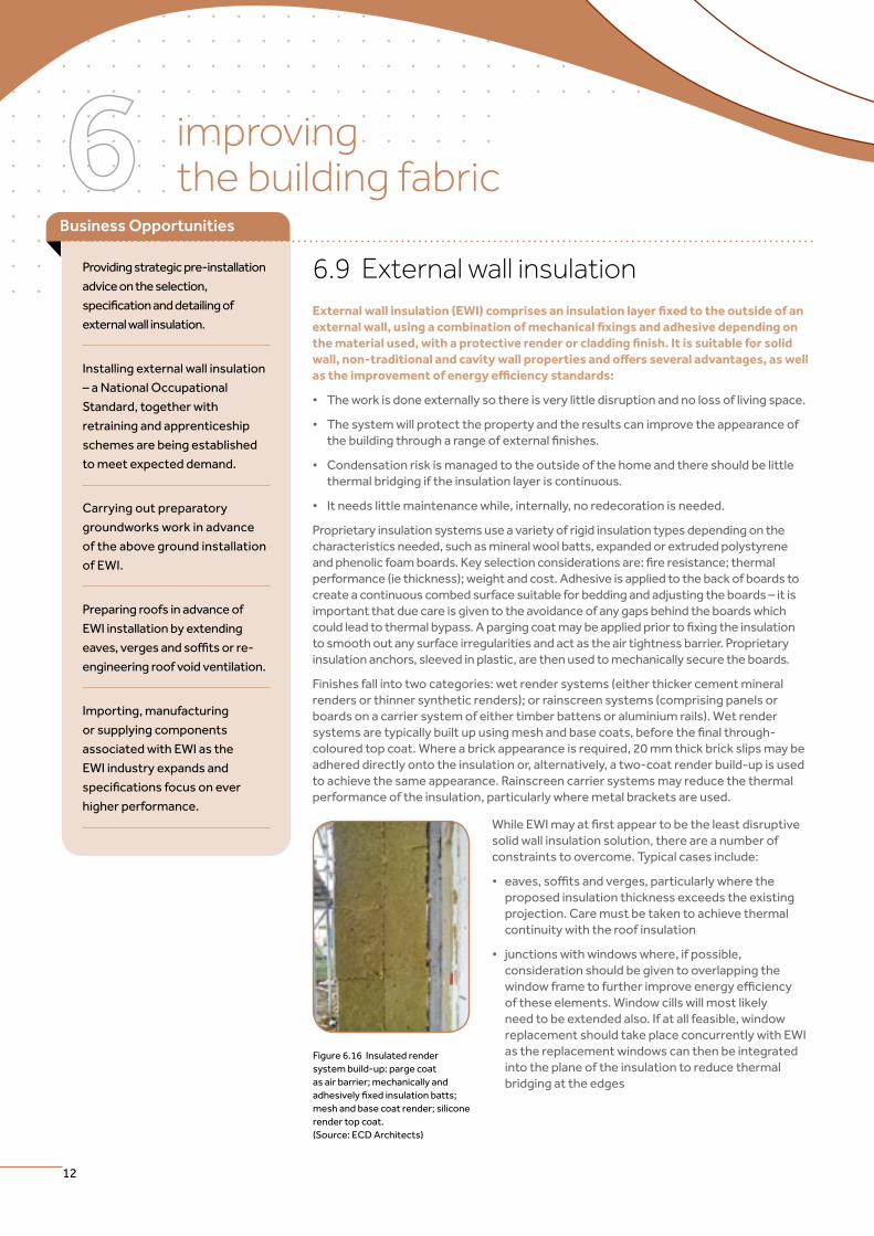
Figure 6.16 Insulated render system build-up: parge coat asairbarrier;mechanicallyandadhesivelyfixedinsulationbatts;meshandbasecoatrender;siliconerender top coat. (Source: ECD Architects)
Providing strategic pre-installation
advice on the selection,
specificationanddetailingof
external wall insulation.
Installing external wall insulation
–aNationalOccupational
Standard, together with
retraining and apprenticeship
schemes are being established
to meet expected demand.
Carrying out preparatory
groundworks work in advance
of the above ground installation
of EWI.
Preparing roofs in advance of
EWI installation by extending
eaves,vergesandsoffitsorre-
engineering roof void ventilation.
Importing, manufacturing
or supplying components
associated with EWI as the
EWI industry expands and
specificationsfocusonever
higher performance.
Business Opportunities
13
building opportunities for business GUIDE 6: improving the building fabric
• architecturalfeaturessuchasbalconies,canopies,baywindowsandsidealleyswillhave to be addressed sympathetically and carefully to maintain the continuity of the insulation
• buildingservicessuchaswastepipework,drainage,flues,ventsandtelecommunicationsequipmentwillallhavetoberemovedandrelocatedonthefaceof the insulation. Typically, a timber pattress is used in the UK to carry the loads to the wall substrate.
Toavoidthermalbridgingatthethresholdbetweengroundfloorandtheexternalgroundand, where it is practical to do so, apron insulation should be installed below DPC level. Closed cell insulation should be used for this purpose, such as extruded polystyrene, fixedinasimilarfashiontoabove-groundEWI.Thisprocesswilloftenrequiretherepositioning of below-ground drainage where gulleys and waste outlets would break the continuity of the EWI system.
Further information on the various approved systems available, the code of professional practice and a directory of contractors can be obtained from the Insulated Render and Cladding Association. Information on external wall insulation solutions can be found in EST (2010), and CPA (2010a), Chapter 5. For advanced EWI standards and methodologies refer to HAZUCHA (2009).
6.10 Internal wall insulation Internal wall insulation (IWI) comprises an insulation layer fixed to the inside of an external wall, using a combination of mechanical fixings and adhesive depending on the material used, with a decorative plasterboard finish. It is suitable for solid wall, non-traditional and cavity wall properties and might be selected over EWI for a number of key reasons, as well as in the improvement of energy efficiency standards:
• Theworkisdoneinternallysothereisnoimpactonplanningpolicy,althoughListedBuildingsmayneedspecificpermission.
• Itcanbeinstalledinoneroomatatimesodisruptionisminimised.
• Installerswillnotneedtousescaffolding.
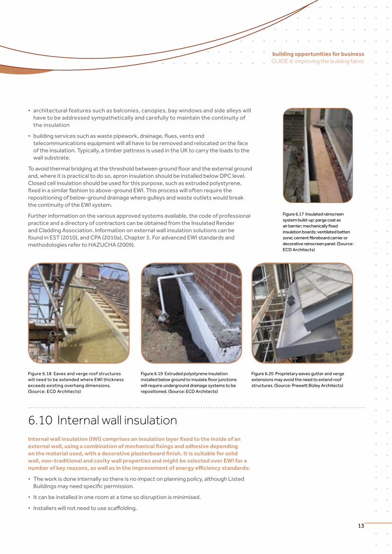
Figure 6.17 Insulated rainscreen system build-up: parge coat as airbarrier;mechanicallyfixedinsulationboards;ventilatedbattenzone;cementfibreboardcarrierordecorative rainscreen panel. (Source: ECD Architects)
Figure 6.18 Eaves and verge roof structures will need to be extended where EWI thickness exceeds existing overhang dimensions. (Source: ECD Architects)
Figure 6.19 Extruded polystyrene insulation installedbelowgroundtoinsulatefloorjunctionswillrequireundergrounddrainagesystemstoberepositioned. (Source: ECD Architects)
Figure 6.20 Proprietary eaves gutter and verge extensions may avoid the need to extend roof structures. (Source: Prewett Bizley Architects)
improving the building fabric
14
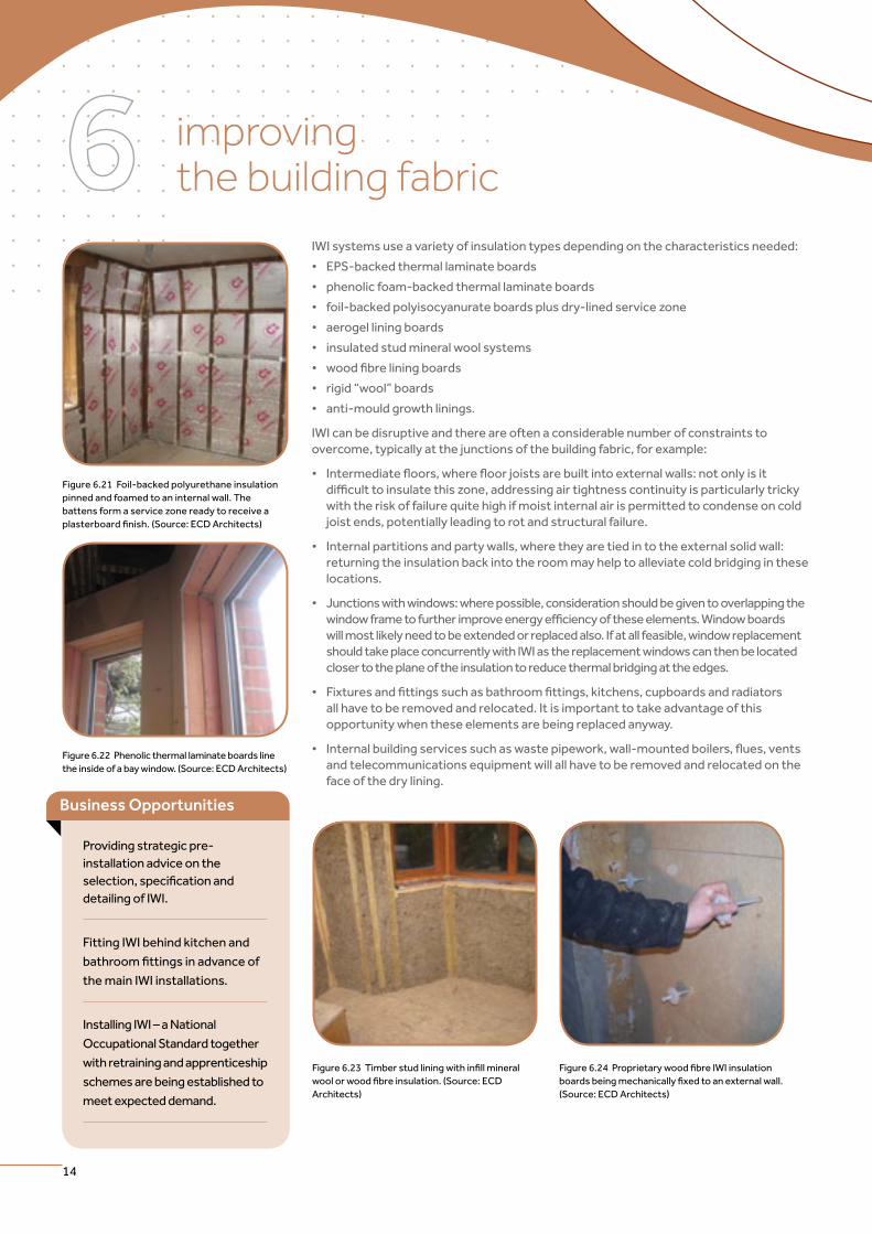
IWI systems use a variety of insulation types depending on the characteristics needed:
• EPS-backedthermallaminateboards
• phenolicfoam-backedthermallaminateboards
• foil-backedpolyisocyanurateboardsplusdry-linedservicezone
• aerogelliningboards
• insulatedstudmineralwoolsystems
• woodfibreliningboards
• rigid“wool”boards
• anti-mouldgrowthlinings.
IWI can be disruptive and there are often a considerable number of constraints to overcome, typically at the junctions of the building fabric, for example:
• Intermediatefloors,wherefloorjoistsarebuiltintoexternalwalls:notonlyisitdifficulttoinsulatethiszone,addressingairtightnesscontinuityisparticularlytrickywiththeriskoffailurequitehighifmoistinternalairispermittedtocondenseoncoldjoist ends, potentially leading to rot and structural failure.
• Internalpartitionsandpartywalls,wheretheyaretiedintotheexternalsolidwall:returning the insulation back into the room may help to alleviate cold bridging in these locations.
• Junctionswithwindows:wherepossible,considerationshouldbegiventooverlappingthewindowframetofurtherimproveenergyefficiencyoftheseelements.Windowboardswill most likely need to be extended or replaced also. If at all feasible, window replacement should take place concurrently with IWI as the replacement windows can then be located closer to the plane of the insulation to reduce thermal bridging at the edges.
• Fixturesandfittingssuchasbathroomfittings,kitchens,cupboardsandradiatorsall have to be removed and relocated. It is important to take advantage of this opportunity when these elements are being replaced anyway.
• Internalbuildingservicessuchaswastepipework,wall-mountedboilers,flues,ventsandtelecommunicationsequipmentwillallhavetoberemovedandrelocatedontheface of the dry lining.
Figure 6.21 Foil-backed polyurethane insulation pinned and foamed to an internal wall. The battens form a service zone ready to receive a plasterboardfinish.(Source:ECDArchitects)
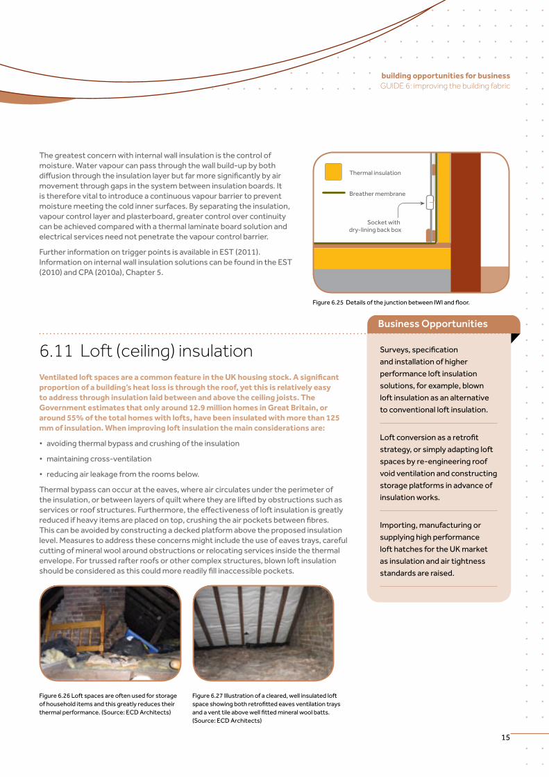
Figure 6.22 Phenolic thermal laminate boards line the inside of a bay window. (Source: ECD Architects)
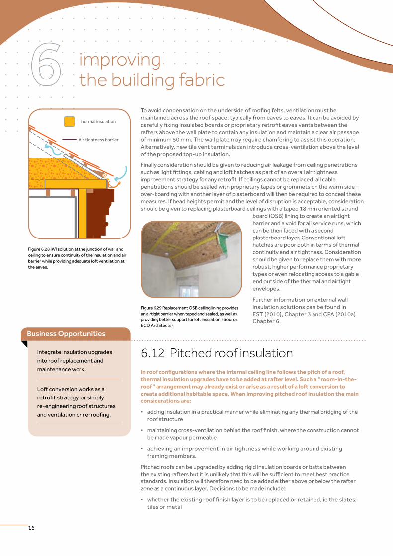
Figure6.23Timberstudliningwithinfillmineralwoolorwoodfibreinsulation.(Source:ECDArchitects)
Figure6.24ProprietarywoodfibreIWIinsulationboardsbeingmechanicallyfixedtoanexternalwall.(Source: ECD Architects)
Socket with dry-lining back box
Thermal insulation
Breather membrane
Figure6.25DetailsofthejunctionbetweenIWIandfloor.
Providing strategic pre-installation advice on the selection,specificationanddetailing of IWI.
Fitting IWI behind kitchen and
bathroomfittingsinadvanceof
the main IWI installations.
InstallingIWI–aNational
Occupational Standard together
with retraining and apprenticeship
schemes are being established to
meet expected demand.
Business Opportunities
15
building opportunities for business GUIDE 6: improving the building fabric
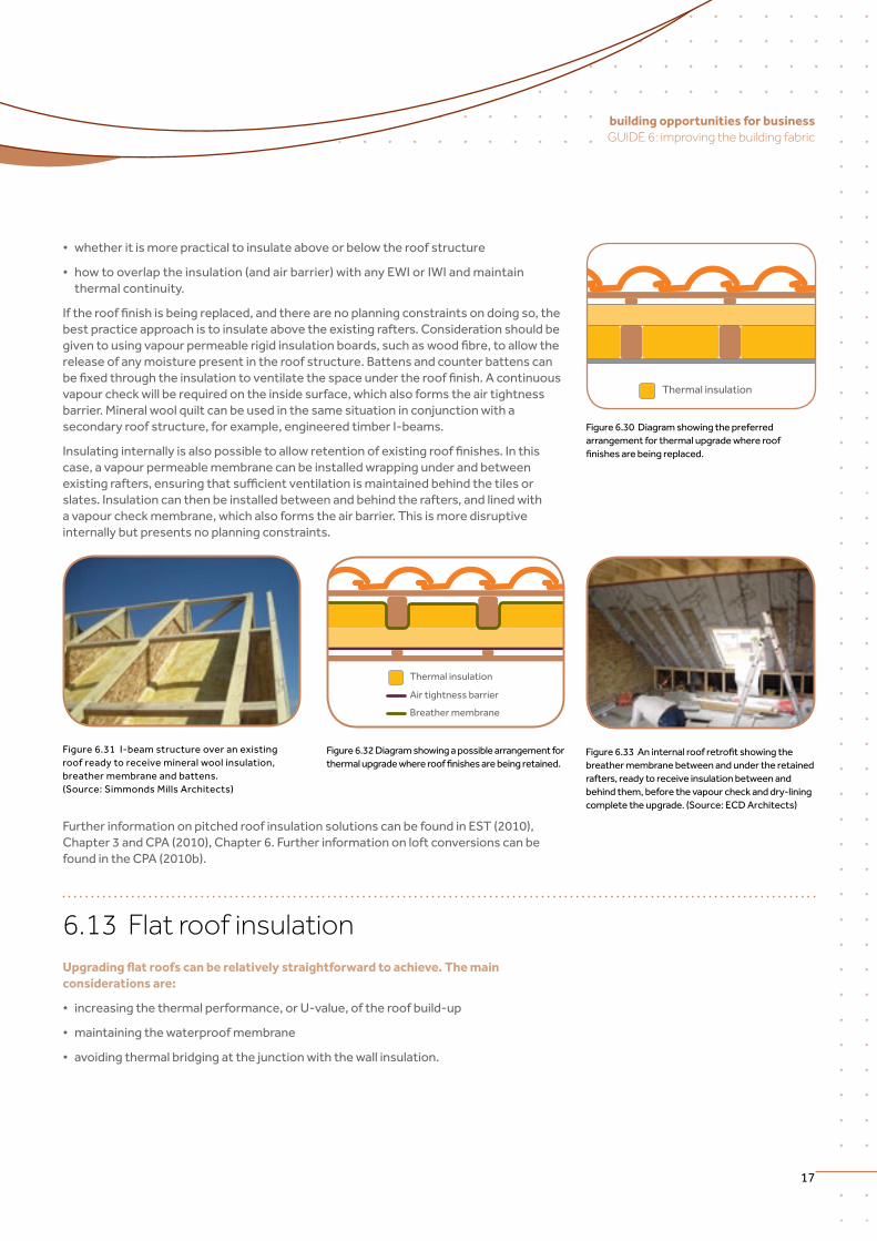
6.11 Loft (ceiling) insulation Ventilated loft spaces are a common feature in the UK housing stock. A significant proportion of a building’s heat loss is through the roof, yet this is relatively easy to address through insulation laid between and above the ceiling joists. The Government estimates that only around 12.9 million homes in Great Britain, or around 55% of the total homes with lofts, have been insulated with more than 125 mm of insulation. When improving loft insulation the main considerations are:
• avoidingthermalbypassandcrushingoftheinsulation
• maintainingcross-ventilation
• reducingairleakagefromtheroomsbelow.
Thermal bypass can occur at the eaves, where air circulates under the perimeter of theinsulation,orbetweenlayersofquiltwheretheyareliftedbyobstructionssuchasservicesorroofstructures.Furthermore,theeffectivenessofloftinsulationisgreatlyreducedifheavyitemsareplacedontop,crushingtheairpocketsbetweenfibres.This can be avoided by constructing a decked platform above the proposed insulation level. Measures to address these concerns might include the use of eaves trays, careful cutting of mineral wool around obstructions or relocating services inside the thermal envelope. For trussed rafter roofs or other complex structures, blown loft insulation shouldbeconsideredasthiscouldmorereadilyfillinaccessiblepockets.
Figure 6.26 Loft spaces are often used for storage of household items and this greatly reduces their thermal performance. (Source: ECD Architects)
Figure 6.27 Illustration of a cleared, well insulated loft spaceshowingbothretrofittedeavesventilationtraysandaventtileabovewellfittedmineralwoolbatts.(Source: ECD Architects)
The greatest concern with internal wall insulation is the control of moisture. Water vapour can pass through the wall build-up by both diffusionthroughtheinsulationlayerbutfarmoresignificantlybyairmovement through gaps in the system between insulation boards. It is therefore vital to introduce a continuous vapour barrier to prevent moisture meeting the cold inner surfaces. By separating the insulation, vapour control layer and plasterboard, greater control over continuity can be achieved compared with a thermal laminate board solution and electrical services need not penetrate the vapour control barrier.
Further information on trigger points is available in EST (2011). Information on internal wall insulation solutions can be found in the EST (2010) and CPA (2010a), Chapter 5.
Figure6.23Timberstudliningwithinfillmineralwoolorwoodfibreinsulation.(Source:ECDArchitects)
Figure6.24ProprietarywoodfibreIWIinsulationboardsbeingmechanicallyfixedtoanexternalwall.(Source: ECD Architects)
Socket with dry-lining back box
Thermal insulation
Breather membrane
Figure6.25DetailsofthejunctionbetweenIWIandfloor.
Surveys,specification
and installation of higher
performance loft insulation
solutions, for example, blown
loft insulation as an alternative
to conventional loft insulation.
Loftconversionasaretrofit
strategy, or simply adapting loft
spaces by re-engineering roof
void ventilation and constructing
storage platforms in advance of
insulation works.
Importing, manufacturing or
supplying high performance
loft hatches for the UK market
as insulation and air tightness
standards are raised.
Business Opportunities
improving the building fabric
16
6.12 Pitched roof insulation In roof configurations where the internal ceiling line follows the pitch of a roof, thermal insulation upgrades have to be added at rafter level. Such a “room-in-the-roof” arrangement may already exist or arise as a result of a loft conversion to create additional habitable space. When improving pitched roof insulation the main considerations are:
• addinginsulationinapracticalmannerwhileeliminatinganythermalbridgingoftheroof structure
• maintainingcross-ventilationbehindtherooffinish,wheretheconstructioncannotbe made vapour permeable
• achievinganimprovementinairtightnesswhileworkingaroundexisting framing members.
Pitched roofs can be upgraded by adding rigid insulation boards or batts between theexistingraftersbutitisunlikelythatthiswillbesufficienttomeetbestpracticestandards. Insulation will therefore need to be added either above or below the rafter zone as a continuous layer. Decisions to be made include:
• whethertheexistingrooffinishlayeristobereplacedorretained,ietheslates,tiles or metal
Toavoidcondensationontheundersideofroofingfelts,ventilationmustbemaintained across the roof space, typically from eaves to eaves. It can be avoided by carefullyfixinginsulatedboardsorproprietaryretrofiteavesventsbetweentherafters above the wall plate to contain any insulation and maintain a clear air passage ofminimum50mm.Thewallplatemayrequirechamferingtoassistthisoperation.Alternatively, new tile vent terminals can introduce cross-ventilation above the level of the proposed top-up insulation.
Finally consideration should be given to reducing air leakage from ceiling penetrations suchaslightfittings,cablingandlofthatchesaspartofanoverallairtightnessimprovementstrategyforanyretrofit.Ifceilingscannotbereplaced,allcablepenetrationsshouldbesealedwithproprietarytapesorgrommetsonthewarmside–over-boardingwithanotherlayerofplasterboardwillthenberequiredtoconcealthesemeasures. If head heights permit and the level of disruption is acceptable, consideration should be given to replacing plasterboard ceilings with a taped 18 mm oriented strand
board (OSB) lining to create an airtight barrier and a void for all service runs, which can be then faced with a second plasterboard layer. Conventional loft hatches are poor both in terms of thermal continuity and air tightness. Consideration should be given to replace them with more robust, higher performance proprietary types or even relocating access to a gable end outside of the thermal and airtight envelopes.
Further information on external wall insulation solutions can be found in EST (2010), Chapter 3 and CPA (2010a) Chapter 6.
Thermal insulation
Air tightness barrier
Figure 6.28 IWI solution at the junction of wall and ceiling to ensure continuity of the insulation and air barrierwhileprovidingadequateloftventilationatthe eaves.
Figure 6.29 Replacement OSB ceiling lining provides an airtight barrier when taped and sealed, as well as providing better support for loft insulation. (Source: ECD Architects)
Integrate insulation upgrades
into roof replacement and
maintenance work.
Loft conversion works as a
retrofitstrategy,orsimply
re-engineering roof structures
andventilationorre-roofing.
Business Opportunities
17
building opportunities for business GUIDE 6: improving the building fabric
• whetheritismorepracticaltoinsulateaboveorbelowtheroofstructure
• howtooverlaptheinsulation(andairbarrier)withanyEWIorIWIandmaintainthermal continuity.
Iftherooffinishisbeingreplaced,andtherearenoplanningconstraintsondoingso,thebest practice approach is to insulate above the existing rafters. Consideration should be giventousingvapourpermeablerigidinsulationboards,suchaswoodfibre,toallowtherelease of any moisture present in the roof structure. Battens and counter battens can befixedthroughtheinsulationtoventilatethespaceundertherooffinish.Acontinuousvapourcheckwillberequiredontheinsidesurface,whichalsoformstheairtightnessbarrier.Mineralwoolquiltcanbeusedinthesamesituationinconjunctionwithasecondary roof structure, for example, engineered timber I-beams.
Insulatinginternallyisalsopossibletoallowretentionofexistingrooffinishes.Inthiscase, a vapour permeable membrane can be installed wrapping under and between existingrafters,ensuringthatsufficientventilationismaintainedbehindthetilesorslates. Insulation can then be installed between and behind the rafters, and lined with a vapour check membrane, which also forms the air barrier. This is more disruptive internally but presents no planning constraints.
Further information on pitched roof insulation solutions can be found in EST (2010), Chapter 3 and CPA (2010), Chapter 6. Further information on loft conversions can be found in the CPA (2010b).
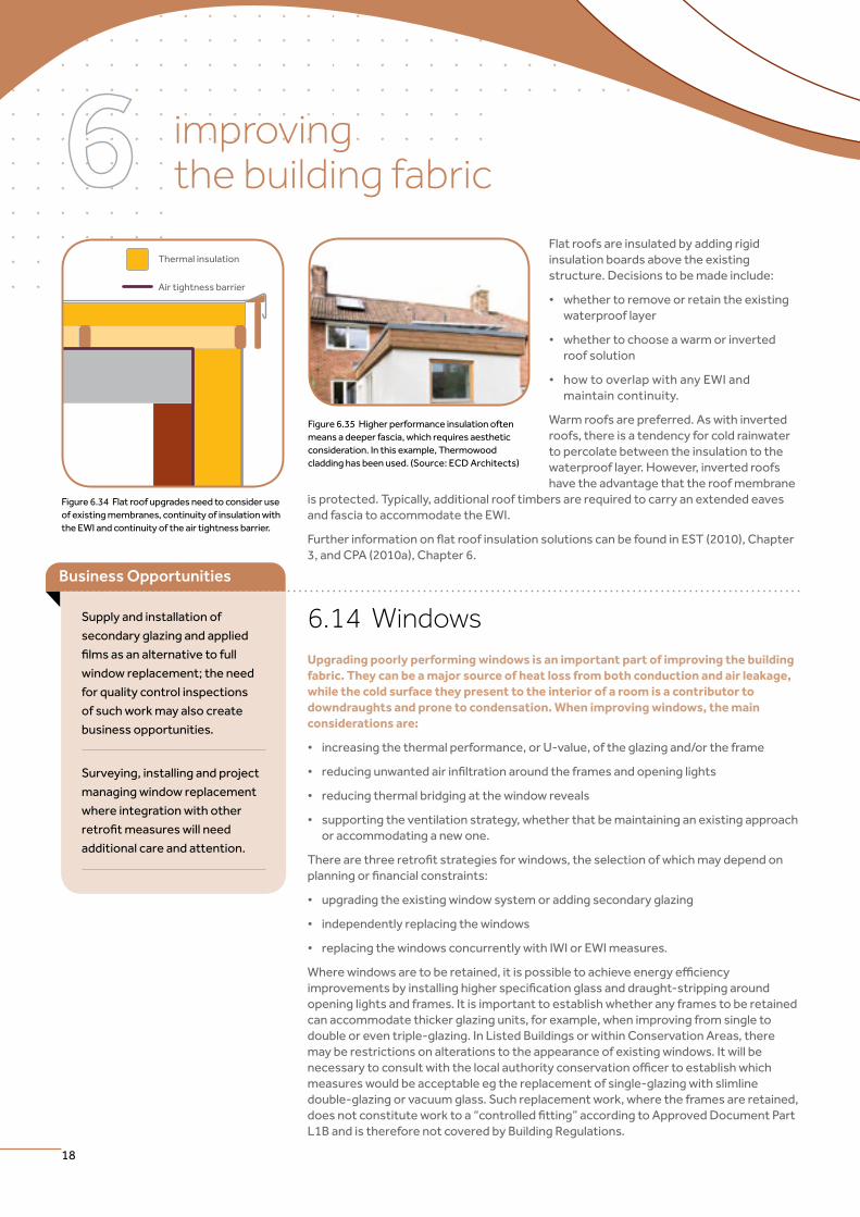
6.13 Flat roof insulation Upgrading flat roofs can be relatively straightforward to achieve. The main considerations are:
• increasingthethermalperformance,orU-value,oftheroofbuild-up
• maintainingthewaterproofmembrane
• avoidingthermalbridgingatthejunctionwiththewallinsulation.
Thermal insulation
Figure 6.30 Diagram showing the preferred arrangement for thermal upgrade where roof finishesarebeingreplaced.
Figure 6.31 I-beam structure over an existing roof ready to receive mineral wool insulation, breather membrane and battens. (Source: Simmonds Mills Architects)
Thermal insulation
Air tightness barrier
Breather membrane
Figure 6.32 Diagram showing a possible arrangement for thermalupgradewhererooffinishesarebeingretained.
Figure6.33Aninternalroofretrofitshowingthebreather membrane between and under the retained rafters, ready to receive insulation between and behind them, before the vapour check and dry-lining complete the upgrade. (Source: ECD Architects)
improving the building fabric
18
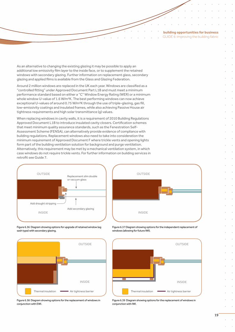
6.14 Windows Upgrading poorly performing windows is an important part of improving the building fabric. They can be a major source of heat loss from both conduction and air leakage, while the cold surface they present to the interior of a room is a contributor to downdraughts and prone to condensation. When improving windows, the main considerations are:
• increasingthethermalperformance,orU-value,oftheglazingand/ortheframe
• reducingunwantedairinfiltrationaroundtheframesandopeninglights
• reducingthermalbridgingatthewindowreveals
• supportingtheventilationstrategy,whetherthatbemaintaininganexistingapproachor accommodating a new one.
Therearethreeretrofitstrategiesforwindows,theselectionofwhichmaydependonplanningorfinancialconstraints:
• upgradingtheexistingwindowsystemoraddingsecondaryglazing
• independentlyreplacingthewindows
• replacingthewindowsconcurrentlywithIWIorEWImeasures.
Wherewindowsaretoberetained,itispossibletoachieveenergyefficiencyimprovementsbyinstallinghigherspecificationglassanddraught-strippingaroundopening lights and frames. It is important to establish whether any frames to be retained can accommodate thicker glazing units, for example, when improving from single to double or even triple-glazing. In Listed Buildings or within Conservation Areas, there may be restrictions on alterations to the appearance of existing windows. It will be necessarytoconsultwiththelocalauthorityconservationofficertoestablishwhichmeasures would be acceptable eg the replacement of single-glazing with slimline double-glazing or vacuum glass. Such replacement work, where the frames are retained, doesnotconstituteworktoa“controlledfitting”accordingtoApprovedDocumentPartL1B and is therefore not covered by Building Regulations.
Flat roofs are insulated by adding rigid insulation boards above the existing structure. Decisions to be made include:
•whethertoremoveorretaintheexistingwaterproof layer
•whethertochooseawarmorinvertedroof solution
•howtooverlapwithanyEWIandmaintain continuity.
Warm roofs are preferred. As with inverted roofs, there is a tendency for cold rainwater to percolate between the insulation to the waterproof layer. However, inverted roofs have the advantage that the roof membrane
isprotected.Typically,additionalrooftimbersarerequiredtocarryanextendedeavesand fascia to accommodate the EWI.
FurtherinformationonflatroofinsulationsolutionscanbefoundinEST(2010),Chapter3, and CPA (2010a), Chapter 6.
Thermal insulation
Air tightness barrier
Figure 6.34 Flat roof upgrades need to consider use of existing membranes, continuity of insulation with the EWI and continuity of the air tightness barrier.
Figure 6.35 Higher performance insulation often meansadeeperfascia,whichrequiresaestheticconsideration. In this example, Thermowood cladding has been used. (Source: ECD Architects)
Business Opportunities
Supply and installation of
secondary glazing and applied
filmsasanalternativetofull
windowreplacement;theneed
forqualitycontrolinspections
of such work may also create
business opportunities.
Surveying, installing and project
managing window replacement
where integration with other
retrofitmeasureswillneed
additional care and attention.
19
building opportunities for business GUIDE 6: improving the building fabric
As an alternative to changing the existing glazing it may be possible to apply an additionallowemissivityfilmlayertotheinsideface,ortosupplementtheretainedwindows with secondary glazing. Further information on replacement glass, secondary glazingandappliedfilmsisavailablefromtheGlassandGlazingFederation.
Around2millionwindowsarereplacedintheUKeachyear.Windowsareclassifiedasa“controlledfitting”underApprovedDocumentPartL1Bandmustmeetaminimumperformance standard based on either a “C” Window Energy Rating (WER) or a minimum whole window U-value of 1.6 W/m²K. The best performing windows can now achieve exceptionalU-valuesofaround0.75W/m²Kthroughtheuseoftriple-glazing,gasfill,low-emissivity coatings and insulated frames, while also achieving Passive House air tightnessrequirementsandhighsolartransmittance(g)values.
Whenreplacingwindowsincavitywalls,itisarequirementof2010BuildingRegulationsApprovedDocumentL1Btointroduceinsulatedcavityclosers.Certificationschemesthatmeetminimumqualityassurancestandards,suchastheFenestrationSelf-Assessment Scheme (FENSA), can alternatively provide evidence of compliance with building regulations. Replacement windows also need to take into consideration the minimumrequirementofApprovedDocumentFwheretrickleventsandopeninglightsform part of the building ventilation solution for background and purge ventilation. Alternatively,thisrequirementmaybemetbyamechanicalventilationsystem,inwhichcasewindowsdonotrequiretricklevents.ForfurtherinformationonbuildingservicesinretrofitseeGuide7.
INSIDE
OUTSIDEReplacement slim double or vacuum glass
Add secondary glazing
Add draught stripping
Figure 6.36 Diagram showing options for upgrade of retained window (eg sash type) with secondary glazing.
INSIDE
OUTSIDE
Figure 6.37 Diagram showing options for the independent replacement of windows (allowing for future IWI).
INSIDE
OUTSIDE
Thermal insulation Air tightness barrier
Figure 6.38 Diagram showing options for the replacement of windows in conjunction with EWI.
INSIDE
OUTSIDE
Thermal insulation Air tightness barrier
Figure 6.39 Diagram showing options for the replacement of windows in conjunction with IWI.
improving the building fabric
20
6.15 External doors As with windows, upgrading doors to improve thermal performance and air tightness should form part of any comprehensive retrofit strategy. Doors are also defined as controlled fittings in the 2010 Building Regulations, but only where door and frame are being replaced simultaneously. The limiting factor for replacement is defined by the maximum permitted U-value of 1.8 W/m²K for the whole door. Therefore, when improving entrance doors, the main considerations are:
• increasingthethermalperformance,orU-value,ofthedoorandtheframe
• reducingunwantedairinfiltrationaroundtheframesandthedoorleaf
• reducingthermalbridgingatthedoorreveals
• accountingforfunctionalaspectssuchassecurityandpostdelivery.
Therearethreeretrofitstrategiesfordoors,theselectionofwhichmaydependonplanning constraints, budget or opportunity:
• upgradingtheexistingdoorleaf
• independentlyreplacingthedoorandframe
• replacingthedoorconcurrentlywithIWIorEWImeasures.
If the door structure allows, it may be possible to refurbish panels in an existing door leaf to introduce insulation in the form of polystyrene, polyurethane or even vacuum-insulated panel(VIP)cores.Newpanellingcouldberetrofittedoutsidetheexistingstiles,mullionsand rails to create a new appearance. Draught stripping should be applied at the same time to reduce unwanted air leakage.
New doors can be obtained that achieve as high a thermal performance as windows at a U-value of 0.8 W/m²K, incorporating triple-glazed lights, pre-insulated cores and double seals.Unlikewindows,doorsshouldusuallybefittedbyscrew-fixingdirectlyintotheadjacent opening jambs in order to be able to cope with the additional stresses created when opening heavy doors.
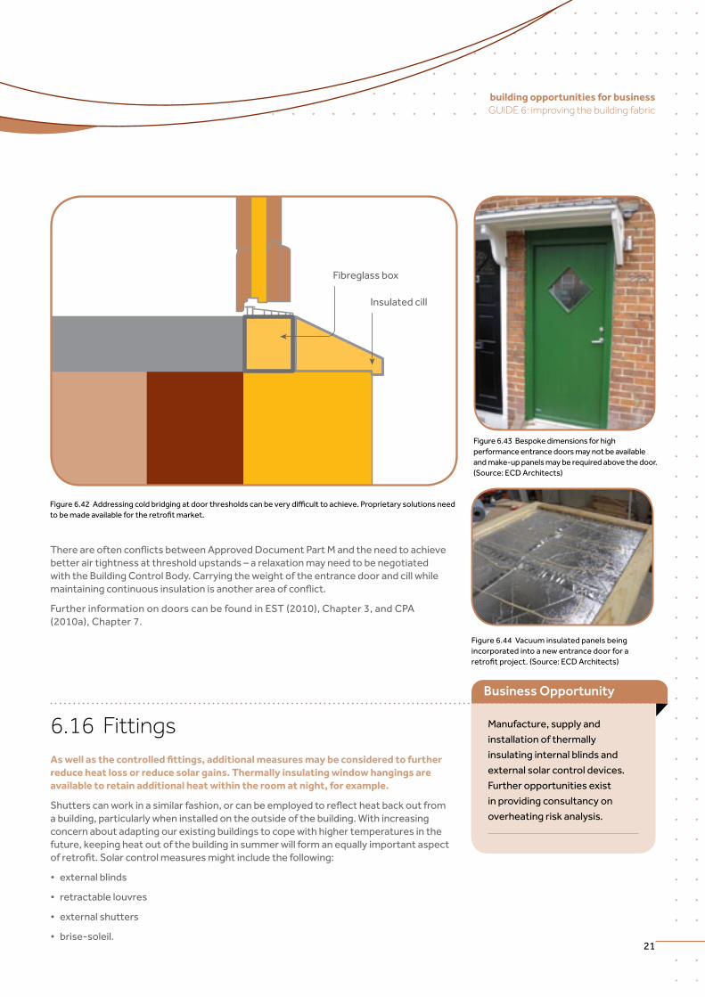
Fibreglass box
Insulated cill
Figure6.42Addressingcoldbridgingatdoorthresholdscanbeverydifficulttoachieve.Proprietarysolutionsneedtobemadeavailablefortheretrofitmarket.
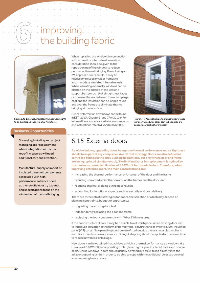
When replacing the windows in conjunction with external or internal wall insulation, consideration should be given to the repositioning of the window to reduce perimeter thermal bridging. If employing an IWI approach, for example, it may be necessary to specify wider frames to accommodate insulated internal reveals. When insulating externally, windows can be planted on the outside of the wall on a support batten such that air tightness tapes can be used to seal between frame and parge coat and the insulation can be lapped round and over the frames to eliminate thermal bridging at the interface.
Further information on windows can be found in EST (2010), Chapter 3, and CPA (2010a). For information about advanced window standards and installations refer to HAZUCHA (2009).
Figure 6.40 Externally insulated frames awaiting EWI to be overlapped. (Source: ECD Architects)
Figure 6.41 Planted high performance window taped to masonry ready for parge coat to be applied and lapped. (Source: ECD Architects)
Surveying, installing and project
managing door replacement
where integration with other
retrofitmeasureswillneed
additional care and attention.
Manufacture, supply or import of
insulated threshold components
associated with high
performance entrance doors
astheretrofitindustryexpands
andspecificationsfocusonthe
elimination of thermal bridging.
Business Opportunities
21
building opportunities for business GUIDE 6: improving the building fabric
ThereareoftenconflictsbetweenApprovedDocumentPartMandtheneedtoachievebetterairtightnessatthresholdupstands–arelaxationmayneedtobenegotiatedwith the Building Control Body. Carrying the weight of the entrance door and cill while maintainingcontinuousinsulationisanotherareaofconflict.
Further information on doors can be found in EST (2010), Chapter 3, and CPA (2010a), Chapter 7.
Figure 6.43 Bespoke dimensions for high performance entrance doors may not be available andmake-uppanelsmayberequiredabovethedoor.(Source: ECD Architects)
Figure 6.44 Vacuum insulated panels being incorporated into a new entrance door for a retrofitproject.(Source:ECDArchitects)
6.15 External doors As with windows, upgrading doors to improve thermal performance and air tightness should form part of any comprehensive retrofit strategy. Doors are also defined as controlled fittings in the 2010 Building Regulations, but only where door and frame are being replaced simultaneously. The limiting factor for replacement is defined by the maximum permitted U-value of 1.8 W/m²K for the whole door. Therefore, when improving entrance doors, the main considerations are:
• increasingthethermalperformance,orU-value,ofthedoorandtheframe
• reducingunwantedairinfiltrationaroundtheframesandthedoorleaf
• reducingthermalbridgingatthedoorreveals
• accountingforfunctionalaspectssuchassecurityandpostdelivery.
Therearethreeretrofitstrategiesfordoors,theselectionofwhichmaydependonplanning constraints, budget or opportunity:
• upgradingtheexistingdoorleaf
• independentlyreplacingthedoorandframe
• replacingthedoorconcurrentlywithIWIorEWImeasures.
If the door structure allows, it may be possible to refurbish panels in an existing door leaf to introduce insulation in the form of polystyrene, polyurethane or even vacuum-insulated panel(VIP)cores.Newpanellingcouldberetrofittedoutsidetheexistingstiles,mullionsand rails to create a new appearance. Draught stripping should be applied at the same time to reduce unwanted air leakage.
New doors can be obtained that achieve as high a thermal performance as windows at a U-value of 0.8 W/m²K, incorporating triple-glazed lights, pre-insulated cores and double seals.Unlikewindows,doorsshouldusuallybefittedbyscrew-fixingdirectlyintotheadjacent opening jambs in order to be able to cope with the additional stresses created when opening heavy doors.
Fibreglass box
Insulated cill
Figure6.42Addressingcoldbridgingatdoorthresholdscanbeverydifficulttoachieve.Proprietarysolutionsneedtobemadeavailablefortheretrofitmarket.
6.16 Fittings As well as the controlled fittings, additional measures may be considered to further reduce heat loss or reduce solar gains. Thermally insulating window hangings are available to retain additional heat within the room at night, for example.
Shutterscanworkinasimilarfashion,orcanbeemployedtoreflectheatbackoutfroma building, particularly when installed on the outside of the building. With increasing concern about adapting our existing buildings to cope with higher temperatures in the future,keepingheatoutofthebuildinginsummerwillformanequallyimportantaspectofretrofit.Solarcontrolmeasuresmightincludethefollowing:
• externalblinds
• retractablelouvres
• externalshutters
• brise-soleil.
Manufacture, supply and
installation of thermally
insulating internal blinds and
external solar control devices.
Further opportunities exist
in providing consultancy on
overheating risk analysis.
Business Opportunity
improving the building fabric
22
6.17 Summary of business opportunitiesThe supply chain for components associated with advanced retrofit, for structural insulation etc is currently under-developed in this country. Opportunities exist to import, manufacture or supply such items as the demand for advanced retrofit expands and specifications focus on ever higher performance with the complete elimination of thermal bridges.
Resident liaison and logistics
Facilitating a temporary decant
Retrofitworksmay,insomecases,behighlydisruptivetoapropertyrequiringresidentsto undertake a temporary decant to allow the works to proceed. Opportunities exist in facilitating this process through resident liaison and removals logistics roles.
Statutory approvals
Planning consultant services
Planningconsentmayberequiredinmanyretrofitscenarios.Opportunitiesexisttoprovideplanning consultant services to negotiate with planning departments, provide “before and after” visualisation and submit applications on behalf of householders or contractors.
Design and modelling
Strategic pre-installation advice
Thereareawiderangeofinsulationtypesandsolutionsavailableforretrofitprojects.Opportunities exist to provide strategic pre-installation advice on the selection, specificationanddetailingofinsulation.
Consultancy in the calculation, or avoidance, of thermal bridging
Modellingoflinearandpointthermalbridgesrequiresspecialised2Dor3Dsoftwareanalysis. Opportunities exist to provide consultancy in the calculation, or avoidance, of thermalbridginginretrofitdesign.
ConsultancyinthePassiveHousedesigntechniques
MeetingthePassiveHouseorEnerPHitstandardsinretrofitrequiresagoodunderstandingofthePassiveHouseprinciplesandtheverificationsoftwareusedinassessing compliance. Opportunities exist to provide consultancy in the Passive House designtechniques,particularlyforCertifiedPassiveHouseDesigners.
Consultancy services providing condensation risk analysis
Itispossibletoaccuratelycalculatevapourdiffusionpatternsinconstructionbuild-ups using specialist software, although this is rarely undertaken in the UK where the steady-state Glaser method prevails. Opportunities exist for consultancy services providing condensation risk analysis using non-stationary analysis such as WUFI. Further opportunities exist to import, manufacture or supply silicate coatings for masonry walls.
23
building opportunities for business GUIDE 6: improving the building fabric
Air tightness
Development, application and training
AirtightretrofittechniquesarepoorlyunderstoodwithintheUKconstructionindustryand specialist skills in this area will need to be improved. Opportunities exist in the development and application of proprietary airtight barriers, membranes, tapes, grommets and seals and in training the workforce to install them correctly. Further opportunitiesmayariseastheneedtofulfiltheroleofairtightnesschampionisincreasingly recognised within the industry.
Air tightness testers
Airtightnesstestingatintermediateandfinalstagesisrecommendedforallretrofitsandisanecessityforadvancedretrofits.Opportunitiesexistforairtightnesstestersmeeting the competent person criteria of the Building Regulations to carry out the growingworkloadassociatedwithlowcarbonretrofit.
Cavity wall insulation
Meetingthedemandforsurveys,specificationandinstallation
There are over 8 million cavities still to be insulated in Great Britain. Opportunities existinmeetingthedemandforsurveys,specificationandinstallation,particularlyintheprivaterentedsectorwherecavityinsulationwillbeoneofthemostcost-effectivemeasures in improving dwellings to the proposed minimum EPC Band E rating.
External wall insulation
Strategic pre-installation advice
Assessing a building’s suitability for EWI will be necessary in advance of the actual measure being carried out. Opportunities exist to provide strategic pre-installation adviceontheselection,specificationanddetailingofexternalwallinsulation.
WiththeproposedlaunchoftheGovernment’senergyefficiencyincentiveschemenextyear, it is estimated that related jobs would have to increase from the current 27,000 toover100,000overthenextfiveyearsiftherequirednumberofhouseholdstakeupthe scheme. It is expected that a large proportion of that number would be engaged ininstallingexternalwallinsulation–aNationalOccupationalStandardtogetherwithretraining and apprenticeship schemes are being established to meet this demand.
Ground workers to carry out preparation work
WhereEWIisproposedbelowDPClevel,alterationswillberequiredtobelow-ground services. Opportunities exist for ground workers to carry out preparation workinadvanceoftheabove-groundEWI–cross-traininginEWIinstallationshould be undertaken.
Carpenters and roof workers to prepare roof construction
WhereEWIinterfaceswithroofcomponents,alterationsmayberequired.Opportunitiesexist for carpenters and roof workers to prepare roof construction in advance of the EWI byextendingeaves,vergesandsoffitsorre-engineeringroofvoidventilation.
improving the building fabric
24
Import, manufacture or supply such items as the EWI industry expands
The supply chain for components associated with EWI, for example, window cill extensions, proprietary eaves extensions, thermally broken bracketry etc, is currently underdeveloped in this country. Opportunities exist to import, manufacture or supply such items as the EWI industry expands and specifications focus on ever higher performance.
Internal wall insulation
Strategicpre-installationadviceonselection,specificationanddetailing
Assessing a building’s suitability for IWI will be necessary in advance of the actual measures being carried out. Opportunities exist to provide strategic pre-installation adviceonselection,specificationanddetailing.
Kitchenandbathroomfitterstointernallyinsulate
IWI should be considered at every available trigger point. Opportunities exist, if appropriatecross-trainingisundertaken,forkitchenandbathroomfitterstointernallyinsulate in advance of such installations.
WiththeproposedlaunchoftheGovernment’senergyefficiencyincentiveschemenextyear, it is estimated that related jobs would have to increase from the current 27,000 toover100,000overthenextfiveyearsiftherequirednumberofhouseholdstakeupthe scheme. It is expected that a good proportion of that number would be engaged ininstallinginternalwallinsulation–aNationalOccupationalStandardtogetherwithretraining and apprenticeship schemes are being established to meet this demand.
Loft and roof improvements
Meetingthedemandforsurveys,specificationandinstallationofhigherperformance loft insulation solutions
There are around 10 million lofts still to be insulated in Great Britain. Opportunities existinmeetingthedemandforsurveys,specificationandinstallationofhigherperformance loft insulation solutions, for example, blown loft insulation as an alternative to conventional loft insulation.
Loftconversionworksasaretrofitstrategy
Adaptingloftspacescanaddvaluetoapropertyaspartoftheretrofitworks.Opportunitiesexistforloftconversionworksasaretrofitstrategyorinsimplyre-engineering roof void ventilation and constructing storage platforms in advance of insulation works.
Import, manufacture or supply of advanced performance loft hatches
Advanced performance loft hatches currently have to be imported from continental suppliers. Opportunities exist in the import, manufacture or supply of such products for the UK market as insulation and air tightness standards are raised.
Roofers to integrate insulation upgrades
Replacementofrooffinishesisakeytriggerpointforcarryingoutthermalupgradessimultaneously. Opportunities exist for roofers to integrate insulation upgrades into their work.
25
building opportunities for business GUIDE 6: improving the building fabric
Glazing and doors
Suppliers and installers of secondary glazing
Opportunities exist for more suppliers and installers of secondary glazing and applied filmsasanalternativetofullwindowreplacement.Theneedforqualitycontrolinspections of such work may also create business opportunities.
Surveying, installing and project-managing window replacement
The current rate of window replacement may increase as a result of Green Deal funding becoming available. Opportunities exist in surveying, installing and project-managing windowreplacementwhereintegrationwithotherretrofitmeasureswillneedadditionalcare and attention.
Surveying, installing and project-managing door replacement
The current rate of door replacement may increase as a result of Green Deal funding becoming available. Opportunities exist in surveying, installing and project-managing doorreplacementwhereintegrationwithotherretrofitmeasureswillneedadditionalcare and attention.
Manufacture,supplyorimportwindowsanddoorsastheretrofitindustry expands
The supply chain for insulated threshold components associated with high performance entrance doors is currently underdeveloped in this country, although pultruded fibreglasscomponentswithinsulatedcoresexist.Opportunitiesexisttomanufacture,supplyorimportsuchitemsastheretrofitindustryexpandsandspecificationsfocusonthe elimination of thermal bridging.
Climate change adaptation
Manufacture, supply and installation of thermally insulating blinds
Most adaptation solutions currently have to be imported from continental suppliers. Opportunities exist for more manufacturers, suppliers and installers of thermally insulating internal blinds and external solar control devices. Further opportunities exist in providing consultancy on overheating risk analysis.
improving the building fabric
26
6.18 Next steps Key referencesCONSTRUCTION PRODUCTS ASSOCIATION (CPA) (2010a) An Introduction to Low Carbon Domestic Refurbishment. Construction Products Association, London, www.constructionproducts.org.uk/publications/Page.aspx?Id=507 [accessed 28/06/11].
CONSTRUCTION PRODUCTS ASSOCIATION (CPA) (2010b) Loft Conversion Project Guide, Construction Products Association, London, www.constructionproducts.org.uk/publications/dbfiles/Loft%20Conversion%20Project%20Guide%20V2%20 Bookmarked.pdf.
ENERGY SAVING TRUST (EST) (2007) Cavity Wall Insulation in Existing Dwellings: A Guide for Specifiers and Advisors CE252, Energy Saving Trust, London, www.energysavingtrust.org.uk/Publication-Download/?p=1&pid=1161avity [accessed 28/06/11].
ENERGY SAVING TRUST (EST) (2010) Sustainable Refurbishment – Towards an 80% Reduction in CO2 Emissions, Water Efficiency,
Waste Reduction, and Climate Change Adaptation, CE309 Energy Saving Trust, London, www.energysavingtrust.org.uk/business/GlobalData/Publications/Sustainable-refurbishment [accessed 28/06/11].
ENERGY SAVING TRUST (EST) (2011) Trigger Points – A Convenient Truth: Promoting Energy Efficiency in the Home, Energy Saving Trust, London, www.energysavingtrust.org.uk/content/download/1998054/6921976/file/i.3285_EST_TriggerPoints%20report%20FINAL%20v2.pdf [accessed 28/06/11].
HAZUCHA,J(2009)Refurbishment of Social Housing – Guidelines for Implementing Whole Building Energy Efficiency Measures, IEE/PASS-NET, www.pass-net.net/downloads/pdf/situation_uk-version.pdf [accessed 28/06/11].
WARD, T and SANDERS, C (2007) Conventions for Calculating Linear Thermal Transmittance and Temperature Factors, BRE Publications, Watford.

27
building opportunities for business GUIDE 6: improving the building fabric
Key LinksFor Building Regulations information: www.communities.gov.uk/planningandbuilding/buildingregulations
For information about the Green Deal from the Department of Energy and Climate Change (DECC): www.decc.gov.uk
ForinformationaboutRetrofitfortheFutureprojects:www.retrofitforthefuture.org and www.innovateuk.org/retrofit
For information about other exemplar projects: www.superhomes.org.uk and www.energysavingtrust.org.uk
For information on Passive House: www.passivhaustrust.org.uk and www.passiv.de
For information on air tightness testing refer to the Airtightness Testing and Measurement Association: www.attma.org
For information about WUFI: www.wufi.de/index_e.html
For information about cavity wall insulation, refer to the Cavity Insulation Guarantee Agency: www.ciga.co.uk
For information about external wall insulation, refer to the Insulated Render and Cladding Association: www.inca-ltd.org.uk
Forfurtherinformationaboutglazingandappliedfilms,refertotheGlassandGlazingFederation: www.ggf.org.uk
AcknowledgementsThese guides have been part-funded by the European Regional Development Fund as part of the Institute for Sustainability’s FLASH programme. This programme aims to provide London-based SMEs with the information and support needed to seize the commercial opportunities arising from the low carbon economy, www.instituteforsustainability.org.uk/FLASH. This guide draws on experience gained on the RetrofitfortheFutureProgrammewhichisfundedby the Technology Strategy Board under the Small Business Research Initiative (SBRI). Further information on the programme can be found at: www.innovateuk.org/retrofit.
Editorial Advisory PanelJulianBoss(InstituteforSustainability)
JohnDoggart(SustainableEnergyAcademy)
Terry McGivern (Institute for Sustainability)
Paul Ruyssevelt (Technology Strategy Board)
Editorial TeamPeterRickaby(RickabyThompsonAssociates)–Managing Editor
Andrew Mellor (PRP)
Nic Wedlake (Peabody)
AuthorsMark Elton (ECD Architects)
NigelGriffiths(AEA)
SebastianJunemann(Peabody)
Andrew Mellor (PRP)
Stephanie Moore (Red Earth PR)
Steve Owen (Ursus Consulting)
Robert Prewett (Prewett Bizley Architects)
LinnRafferty(JTecEnergyPerformance)
Peter Rickaby (Rickaby Thompson Associates)
Luke Smith (Fusion21)
Russell Smith (Parity Projects)
David Turrent (ECD Architects)
Liz Warren (SE2)
Nic Wedlake (Peabody)
JohnWilloughby
DesignPhilipGoldfinch(LimeCreative)
AbiGoldfinch(LimeCreative)
Andrew Byrne (Lime Creative)
Amy Derrington (Lime Creative)
Lei Ouyang (Lime Creative)
ProofreadingRachael Oakley (Byline Publishing)
Catherine Anderson (Byline Publishing)
Technical SupportKathryn Derby (Rickaby Thompson Associates)
http://www.instituteforsustainability.co.uk
Contact information:
[email protected] www.instituteforsustainability.org.uk
Registered Charity No. 1128884 Registered in England number 06856082
© 2011 Institute for Sustainability