Embed Size (px)
Citation preview
Proceedings of the 18th Association of Public Authority Surveyors Conference (APAS2013) Canberra, Australian Capital Territory, Australia, 12-14 March 2013
187
Improving Survey Infrastructure in NSW: Construction of
the Eglinton EDM Baseline
Dick Ellis Survey Infrastructure and Geodesy, Land and Property Information
NSW Department of Finance & Services [email protected]
Volker Janssen Survey Infrastructure and Geodesy, Land and Property Information
NSW Department of Finance & Services [email protected]
Robert Lock Survey Infrastructure and Geodesy, Land and Property Information
NSW Department of Finance & Services [email protected]
ABSTRACT The Surveyor General is a Verifying Authority under the National Measurement Act 1960 and responsible for ensuring that surveyors use verified measuring equipment. This is achieved, for example, through the provision and maintenance of Electronic Distance Measurement (EDM) baselines. Consequently, the Surveying and Spatial Information Regulation 2012 requires surveyors to verify their measuring equipment in relation to an Australian standard of measurement of length at least once a year. Land and Property Information (LPI) is the sole organisation responsible for constructing, maintaining, monitoring and verifying all these baselines within New South Wales. LPI is currently in the process of improving its survey infrastructure by upgrading existing baselines if possible (to include a larger number of pillars) and building new baselines for the calibration of EDM instruments. This paper outlines the issues that need to be considered in the construction of a state-of-the-art EDM baseline, using the newly constructed 7-pillar Eglinton EDM baseline (located in Bathurst) as an example. Topics covered include site selection, planning, logistics, Work Health and Safety considerations, pillar construction and baseline verification. KEYWORDS: EDM, baseline calibration, survey infrastructure, legal metrology. 1 INTRODUCTION The Surveyor General is a Verifying Authority for reference standards of measurement under the National Measurement Act 1960 (Australian Government, 2013a) and in accordance with the National Measurement Regulations 1999 (Australian Government, 2013b), thereby being responsible for ensuring that surveyors use verified measuring equipment. Consequently, the Surveying and Spatial Information Regulation 2012 (NSW Legislation, 2013) requires surveyors to verify their measuring equipment in relation to an Australian or state primary standard of measurement of length at least once a year. This instrument verification establishes traceability of its measurements to the national standard.
Proceedings of the 18th Association of Public Authority Surveyors Conference (APAS2013) Canberra, Australian Capital Territory, Australia, 12-14 March 2013
188
Since the beginning of the 20th century, the Surveyor General has been responsible for the standardisation of length. Initially, the task of standardising steel bands was carried out in the basement of the old Lands Department building in Bridge Street, Sydney. Following the introduction of Electronic Distance Measurement (EDM) instruments in the 1970s (e.g. Rüeger, 1996), the Surveyor General has been responsible for establishing and maintaining baselines for the calibration of such instruments. Fulfilling the role of the Surveyor General, Land and Property Information (LPI) is the sole organisation responsible for setting standards and providing infrastructure for EDM calibrations in NSW. In 1983, the Surveyors General of the Australian states and territories introduced a new national EDM calibration scheme under the National Measurement Act. A working party on the calibration of EDM equipment was established by the National Standards Commission (now the National Measurement Institute, NMI) and met on 1 February 1983. It prepared eight recommendations on how legal traceability to the national standards of physical measurements could be provided for practicing surveyors using EDM instruments. These recommendations – see Rüeger (1985) for details – were endorsed by the Commission at its 85th meeting on 9 February 1983 and resulted in documented instructions regarding the field observations and analysis procedures for the calibration of EDM instruments on baselines (Rüeger, 1984). Initially, the EDM baselines constructed in NSW consisted of three or four concrete pillars. Two baselines have since been extended to include more pillars, i.e. Dubbo in June 1999 and Kingscliff in June 2008 (Table 1). The field procedures currently prescribed for EDM calibrations in NSW are documented in Surveyor General’s Direction No. 5: Verification of Distance Measuring Equipment (LPI, 2009).
Table 1: EDM baselines in NSW (before the most recent modernisation efforts).
Baseline Length (m) No. of Pillars Year of Construction Armidale 600 4 1984 Bankstown 605 4 1984 Bathurst 888 4 1979 Bega 503 4 1984 Blacktown 465 3 1982 Dubbo 650 (765) 4 (6) 1984 (1999) Goulburn 497 4 1984 Grafton 610 4 1984 Kingscliff 600 (721) 4 (7) 1989 (2008) Moruya 429 4 1986 Newcastle 611 4 1982 Nowra 581 4 1984 Tamworth 550 4 1984 Taree 515 4 1984 Ulan Coal (near Mudgee) 650 6 2002 Wagga Wagga 535 5 1984 Wakehurst 430 3 1979 Wollongong 600 4 1983
The EDM instrument correction is dependent on many variables, including distance, temperature, time, supply voltage and ambient atmospheric conditions (Rüeger, 1996). It comprises at least two terms, i.e. the additive constant (a constant term expressed in mm) and the scale correction (a linear distance-dependent term expressed in ppm), with additional terms added to describe the instrument correction in more detail (e.g. including non-linear
Proceedings of the 18th Association of Public Authority Surveyors Conference (APAS2013) Canberra, Australian Capital Territory, Australia, 12-14 March 2013
189
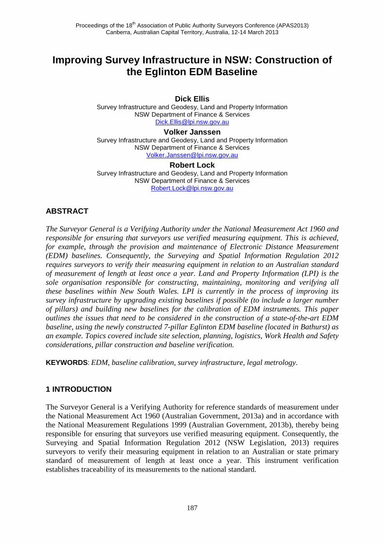
distance-dependent terms and cyclic error terms). However, it should be noted that it is not possible to determine instrument corrections with more than six parameters on 4-pillar baselines (Rüeger, 1991). Current best practice has established that EDM baselines should consist of at least five (and preferably six or seven) pillars to increase the number of distances observed, thereby allowing a more reliable determination of the instrument correction. This has led to LPI’s commitment to improve its survey infrastructure for the calibration of EDM instruments by upgrading existing baselines to include a larger number of pillars if possible. Consequently, the Dubbo and Kingscliff EDM baselines have been successfully upgraded to include six and seven pillars, respectively (see Table 1). However, such a baseline expansion is often extremely difficult in practice. Alternatively, new baselines are being built to replace existing ones that cannot be upgraded. The first new 7-pillar baseline was constructed in Lethbridge Park (located in western Sydney) in mid 2012. This paper focuses on the Eglinton EDM baseline in Bathurst, also constructed in 2012, in order to outline the issues that need to be considered in the construction of a modern EDM baseline. 2 DESIGNING A NEW EDM BASELINE FOR BATHURST 2.1 Background The existing 4-pillar EDM baseline in Bathurst has been in use since its construction by the Central Mapping Authority (CMA) in 1979. The location at the base of Mt Panorama on Crown land was deemed ideal at the time, with easy access to the CMA building. Geodetic and mapping work was booming, and the baseline was constantly being used internally and externally to verify the numerous EDM instruments in use. However, it was found that a combination of slope and soil type meant that following each period of either drought or increased rain the pillars appeared to move slowly downhill, at different and unpredictable rates (Figures 1 & 2). The problem was exacerbated by the construction of a contour bank immediately below the second pillar, which pooled water for an extended period after heavy rain events, as well as a council gravel stockpile constructed on line with the baseline (Figure 3). In the early 2000s, it was decided that the Bathurst EDM baseline could not be maintained into the future. It was felt by local surveyors that travel to Dubbo (6 pillars), Ulan Coal near Mudgee (6 pillars) or western Sydney (4 pillars) was not a cost-effective option. Consequently, investigations into an alternative EDM baseline site in the general area around Bathurst commenced in mid 2007. In order to provide high-quality survey infrastructure far into the future, it was decided to build a 7-pillar baseline.
Figure 1: (a) Pillar 1 looking north along Bathurst baseline (note rifle range to the east), and (b) Pillar 1 looking
south (note effects of erosion).
(a) (b)
Proceedings of the 18th Association of Public Authority Surveyors Conference (APAS2013) Canberra, Australian Capital Territory, Australia, 12-14 March 2013
190
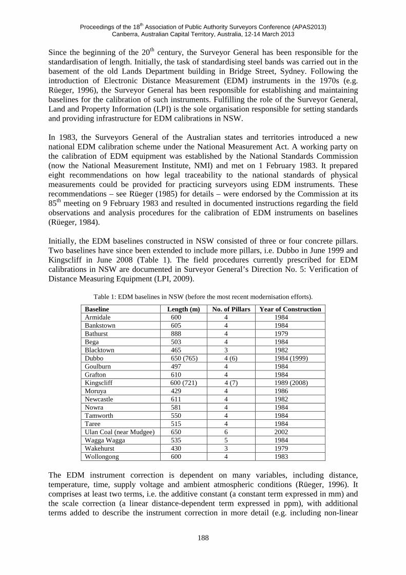
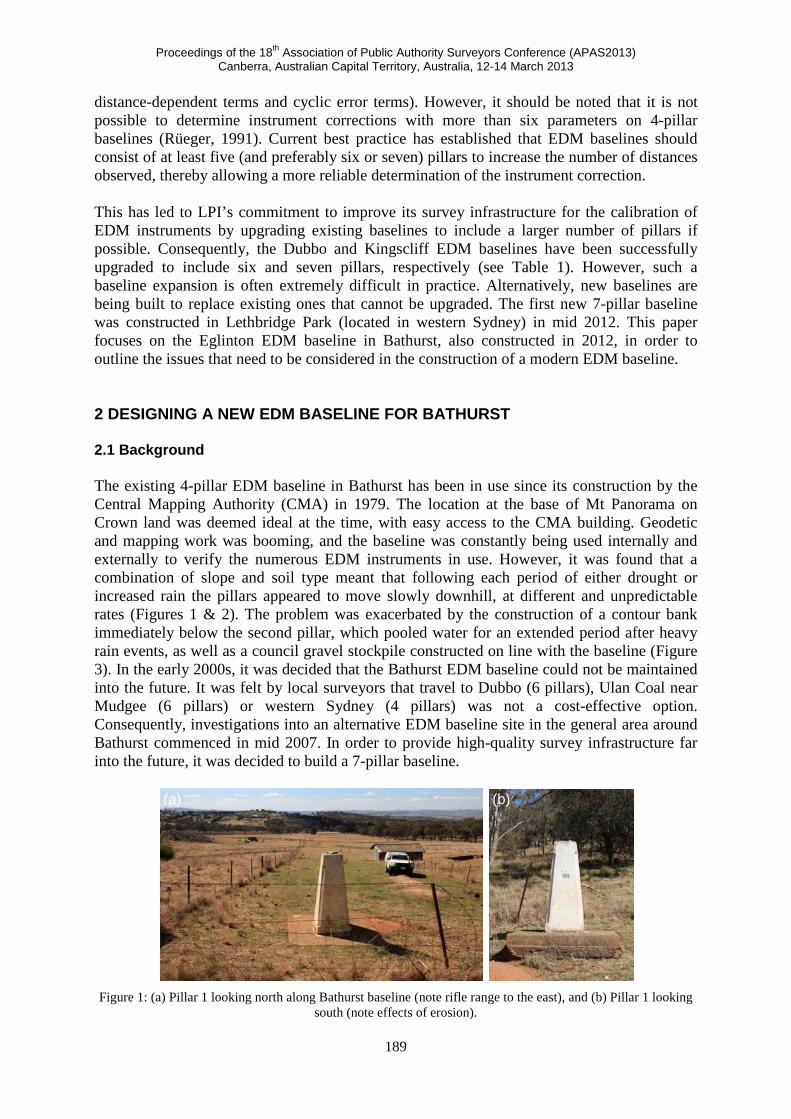
Figure 2: Pillar 3 looking south (note rifle range abutments and steep slope).
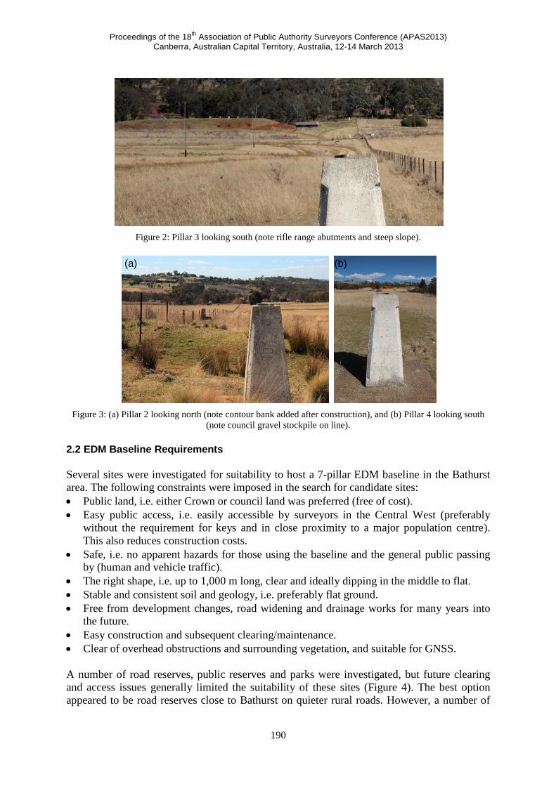
Figure 3: (a) Pillar 2 looking north (note contour bank added after construction), and (b) Pillar 4 looking south
(note council gravel stockpile on line). 2.2 EDM Baseline Requirements Several sites were investigated for suitability to host a 7-pillar EDM baseline in the Bathurst area. The following constraints were imposed in the search for candidate sites: • Public land, i.e. either Crown or council land was preferred (free of cost). • Easy public access, i.e. easily accessible by surveyors in the Central West (preferably
without the requirement for keys and in close proximity to a major population centre). This also reduces construction costs.
• Safe, i.e. no apparent hazards for those using the baseline and the general public passing by (human and vehicle traffic).
• The right shape, i.e. up to 1,000 m long, clear and ideally dipping in the middle to flat. • Stable and consistent soil and geology, i.e. preferably flat ground. • Free from development changes, road widening and drainage works for many years into
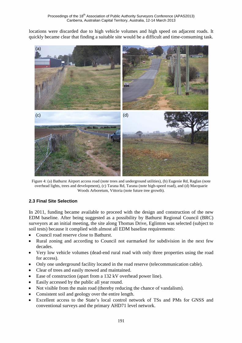
the future. • Easy construction and subsequent clearing/maintenance. • Clear of overhead obstructions and surrounding vegetation, and suitable for GNSS. A number of road reserves, public reserves and parks were investigated, but future clearing and access issues generally limited the suitability of these sites (Figure 4). The best option appeared to be road reserves close to Bathurst on quieter rural roads. However, a number of
(a) (b)
Proceedings of the 18th Association of Public Authority Surveyors Conference (APAS2013) Canberra, Australian Capital Territory, Australia, 12-14 March 2013
191
locations were discarded due to high vehicle volumes and high speed on adjacent roads. It quickly became clear that finding a suitable site would be a difficult and time-consuming task.
Figure 4: (a) Bathurst Airport access road (note trees and underground utilities), (b) Eugenie Rd, Raglan (note
overhead lights, trees and development), (c) Tarana Rd, Tarana (note high-speed road), and (d) Macquarie Woods Arboretum, Vittoria (note future tree growth).
2.3 Final Site Selection In 2011, funding became available to proceed with the design and construction of the new EDM baseline. After being suggested as a possibility by Bathurst Regional Council (BRC) surveyors at an initial meeting, the site along Thomas Drive, Eglinton was selected (subject to soil tests) because it complied with almost all EDM baseline requirements: • Council road reserve close to Bathurst. • Rural zoning and according to Council not earmarked for subdivision in the next few
decades. • Very low vehicle volumes (dead-end rural road with only three properties using the road
for access). • Only one underground facility located in the road reserve (telecommunication cable). • Clear of trees and easily mowed and maintained. • Ease of construction (apart from a 132 kV overhead power line). • Easily accessed by the public all year round. • Not visible from the main road (thereby reducing the chance of vandalism). • Consistent soil and geology over the entire length. • Excellent access to the State’s local control network of TSs and PMs for GNSS and
conventional surveys and the primary AHD71 level network.
(a) (b)
(c) (d)
Proceedings of the 18th Association of Public Authority Surveyors Conference (APAS2013) Canberra, Australian Capital Territory, Australia, 12-14 March 2013
192
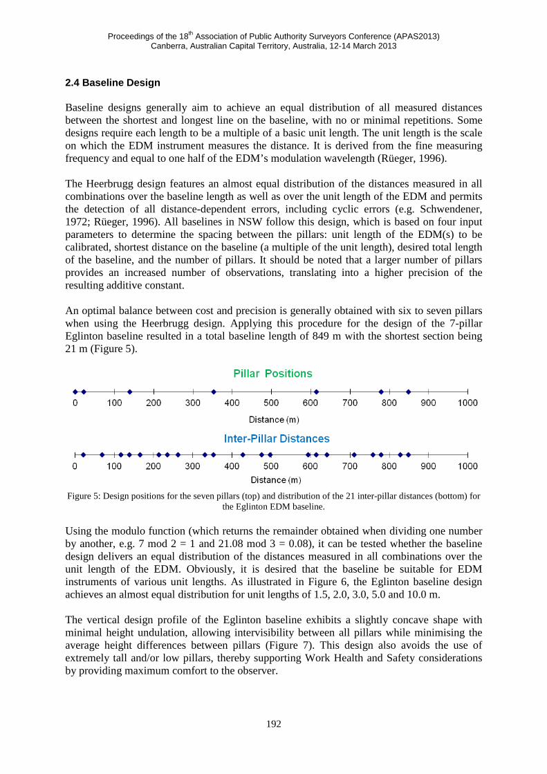
2.4 Baseline Design Baseline designs generally aim to achieve an equal distribution of all measured distances between the shortest and longest line on the baseline, with no or minimal repetitions. Some designs require each length to be a multiple of a basic unit length. The unit length is the scale on which the EDM instrument measures the distance. It is derived from the fine measuring frequency and equal to one half of the EDM’s modulation wavelength (Rüeger, 1996). The Heerbrugg design features an almost equal distribution of the distances measured in all combinations over the baseline length as well as over the unit length of the EDM and permits the detection of all distance-dependent errors, including cyclic errors (e.g. Schwendener, 1972; Rüeger, 1996). All baselines in NSW follow this design, which is based on four input parameters to determine the spacing between the pillars: unit length of the EDM(s) to be calibrated, shortest distance on the baseline (a multiple of the unit length), desired total length of the baseline, and the number of pillars. It should be noted that a larger number of pillars provides an increased number of observations, translating into a higher precision of the resulting additive constant. An optimal balance between cost and precision is generally obtained with six to seven pillars when using the Heerbrugg design. Applying this procedure for the design of the 7-pillar Eglinton baseline resulted in a total baseline length of 849 m with the shortest section being 21 m (Figure 5).
Figure 5: Design positions for the seven pillars (top) and distribution of the 21 inter-pillar distances (bottom) for
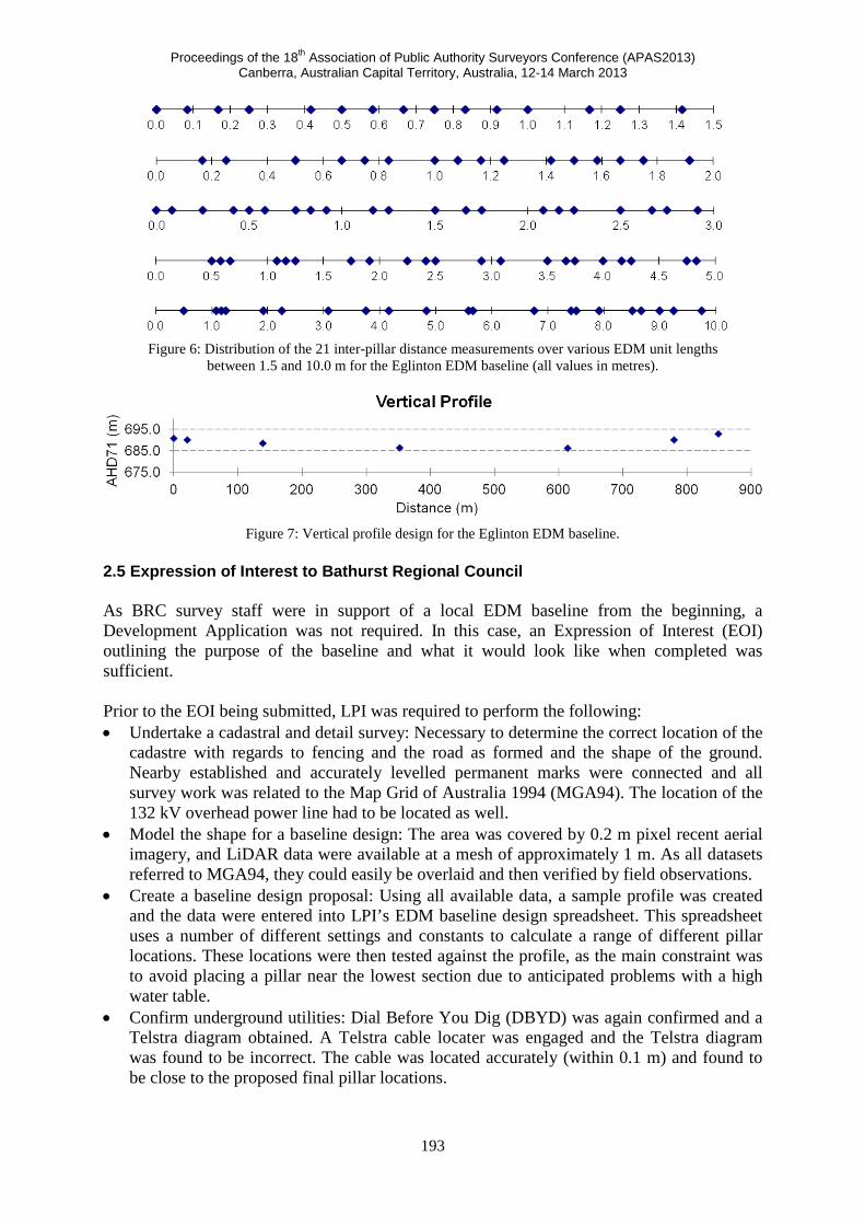
the Eglinton EDM baseline. Using the modulo function (which returns the remainder obtained when dividing one number by another, e.g. 7 mod 2 = 1 and 21.08 mod 3 = 0.08), it can be tested whether the baseline design delivers an equal distribution of the distances measured in all combinations over the unit length of the EDM. Obviously, it is desired that the baseline be suitable for EDM instruments of various unit lengths. As illustrated in Figure 6, the Eglinton baseline design achieves an almost equal distribution for unit lengths of 1.5, 2.0, 3.0, 5.0 and 10.0 m. The vertical design profile of the Eglinton baseline exhibits a slightly concave shape with minimal height undulation, allowing intervisibility between all pillars while minimising the average height differences between pillars (Figure 7). This design also avoids the use of extremely tall and/or low pillars, thereby supporting Work Health and Safety considerations by providing maximum comfort to the observer.
Proceedings of the 18th Association of Public Authority Surveyors Conference (APAS2013) Canberra, Australian Capital Territory, Australia, 12-14 March 2013
193
Figure 6: Distribution of the 21 inter-pillar distance measurements over various EDM unit lengths
between 1.5 and 10.0 m for the Eglinton EDM baseline (all values in metres).
Figure 7: Vertical profile design for the Eglinton EDM baseline.
2.5 Expression of Interest to Bathurst Regional Council As BRC survey staff were in support of a local EDM baseline from the beginning, a Development Application was not required. In this case, an Expression of Interest (EOI) outlining the purpose of the baseline and what it would look like when completed was sufficient. Prior to the EOI being submitted, LPI was required to perform the following: • Undertake a cadastral and detail survey: Necessary to determine the correct location of the
cadastre with regards to fencing and the road as formed and the shape of the ground. Nearby established and accurately levelled permanent marks were connected and all survey work was related to the Map Grid of Australia 1994 (MGA94). The location of the 132 kV overhead power line had to be located as well.
• Model the shape for a baseline design: The area was covered by 0.2 m pixel recent aerial imagery, and LiDAR data were available at a mesh of approximately 1 m. As all datasets referred to MGA94, they could easily be overlaid and then verified by field observations.
• Create a baseline design proposal: Using all available data, a sample profile was created and the data were entered into LPI’s EDM baseline design spreadsheet. This spreadsheet uses a number of different settings and constants to calculate a range of different pillar locations. These locations were then tested against the profile, as the main constraint was to avoid placing a pillar near the lowest section due to anticipated problems with a high water table.
• Confirm underground utilities: Dial Before You Dig (DBYD) was again confirmed and a Telstra diagram obtained. A Telstra cable locater was engaged and the Telstra diagram was found to be incorrect. The cable was located accurately (within 0.1 m) and found to be close to the proposed final pillar locations.
Proceedings of the 18th Association of Public Authority Surveyors Conference (APAS2013) Canberra, Australian Capital Territory, Australia, 12-14 March 2013
194
• Peg-out proposed pillar locations and create digital images: The initially proposed pillar locations were pegged and heighted to confirm profile design was correct, and then digital images were taken of each pillar site.
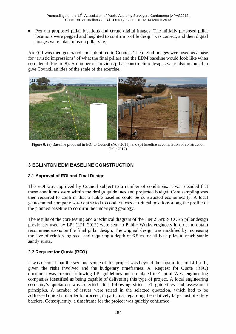
An EOI was then generated and submitted to Council. The digital images were used as a base for ‘artistic impressions’ of what the final pillars and the EDM baseline would look like when completed (Figure 8). A number of previous pillar construction designs were also included to give Council an idea of the scale of the exercise.
Figure 8: (a) Baseline proposal in EOI to Council (Nov 2011), and (b) baseline at completion of construction
(July 2012). 3 EGLINTON EDM BASELINE CONSTRUCTION 3.1 Approval of EOI and Final Design The EOI was approved by Council subject to a number of conditions. It was decided that these conditions were within the design guidelines and projected budget. Core sampling was then required to confirm that a stable baseline could be constructed economically. A local geotechnical company was contracted to conduct tests at critical positions along the profile of the planned baseline to confirm the underlying geology. The results of the core testing and a technical diagram of the Tier 2 GNSS CORS pillar design previously used by LPI (LPI, 2012) were sent to Public Works engineers in order to obtain recommendations on the final pillar design. The original design was modified by increasing the size of reinforcing steel and requiring a depth of 6.5 m for all base piles to reach stable sandy strata. 3.2 Request for Quote (RFQ) It was deemed that the size and scope of this project was beyond the capabilities of LPI staff, given the risks involved and the budgetary timeframes. A Request for Quote (RFQ) document was created following LPI guidelines and circulated to Central West engineering companies identified as being capable of delivering this type of project. A local engineering company’s quotation was selected after following strict LPI guidelines and assessment principles. A number of issues were raised in the selected quotation, which had to be addressed quickly in order to proceed, in particular regarding the relatively large cost of safety barriers. Consequently, a timeframe for the project was quickly confirmed.
(a) (b)
Proceedings of the 18th Association of Public Authority Surveyors Conference (APAS2013) Canberra, Australian Capital Territory, Australia, 12-14 March 2013
195
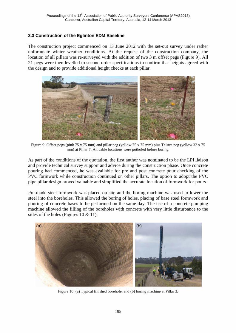
3.3 Construction of the Eglinton EDM Baseline The construction project commenced on 13 June 2012 with the set-out survey under rather unfortunate winter weather conditions. At the request of the construction company, the location of all pillars was re-surveyed with the addition of two 3 m offset pegs (Figure 9). All 21 pegs were then levelled to second order specifications to confirm that heights agreed with the design and to provide additional height checks at each pillar.
Figure 9: Offset pegs (pink 75 x 75 mm) and pillar peg (yellow 75 x 75 mm) plus Telstra peg (yellow 32 x 75
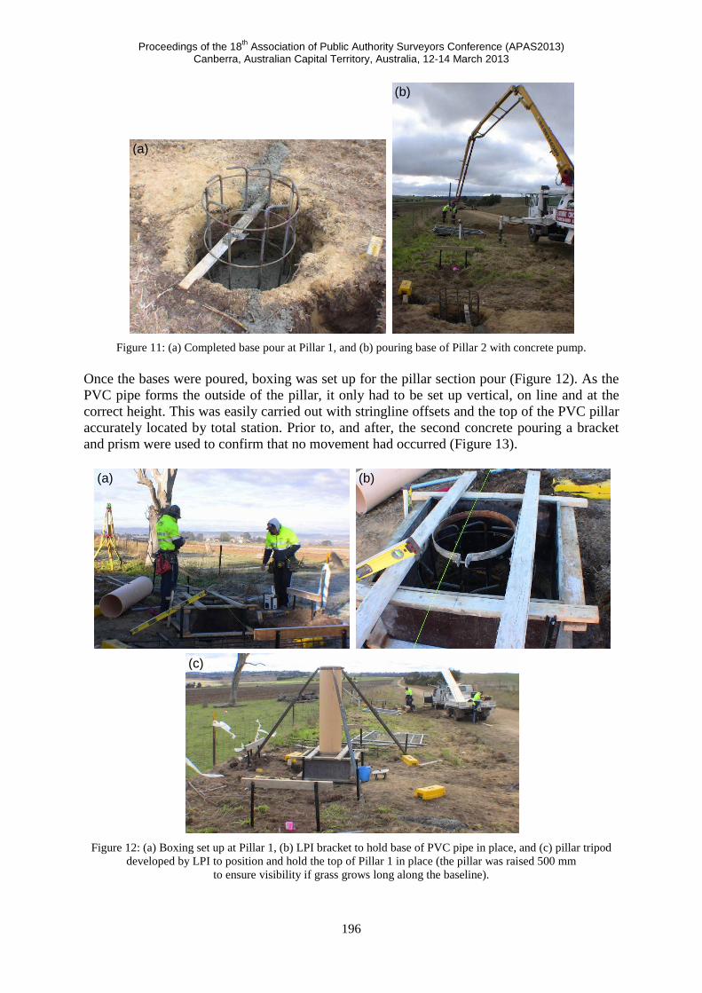
mm) at Pillar 7. All cable locations were potholed before boring. As part of the conditions of the quotation, the first author was nominated to be the LPI liaison and provide technical survey support and advice during the construction phase. Once concrete pouring had commenced, he was available for pre and post concrete pour checking of the PVC formwork while construction continued on other pillars. The option to adopt the PVC pipe pillar design proved valuable and simplified the accurate location of formwork for pours. Pre-made steel formwork was placed on site and the boring machine was used to lower the steel into the boreholes. This allowed the boring of holes, placing of base steel formwork and pouring of concrete bases to be performed on the same day. The use of a concrete pumping machine allowed the filling of the boreholes with concrete with very little disturbance to the sides of the holes (Figures 10 & 11).
Figure 10: (a) Typical finished borehole, and (b) boring machine at Pillar 3.
(a) (b)
Proceedings of the 18th Association of Public Authority Surveyors Conference (APAS2013) Canberra, Australian Capital Territory, Australia, 12-14 March 2013
196
Figure 11: (a) Completed base pour at Pillar 1, and (b) pouring base of Pillar 2 with concrete pump.
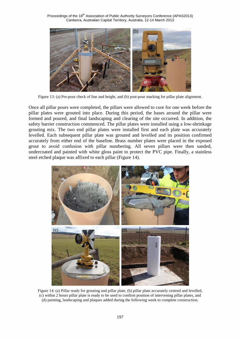
Once the bases were poured, boxing was set up for the pillar section pour (Figure 12). As the PVC pipe forms the outside of the pillar, it only had to be set up vertical, on line and at the correct height. This was easily carried out with stringline offsets and the top of the PVC pillar accurately located by total station. Prior to, and after, the second concrete pouring a bracket and prism were used to confirm that no movement had occurred (Figure 13).
Figure 12: (a) Boxing set up at Pillar 1, (b) LPI bracket to hold base of PVC pipe in place, and (c) pillar tripod
developed by LPI to position and hold the top of Pillar 1 in place (the pillar was raised 500 mm to ensure visibility if grass grows long along the baseline).
(a)
(a) (b)
(c)
(b)
Proceedings of the 18th Association of Public Authority Surveyors Conference (APAS2013) Canberra, Australian Capital Territory, Australia, 12-14 March 2013
197
Figure 13: (a) Pre-pour check of line and height, and (b) post-pour marking for pillar plate alignment.
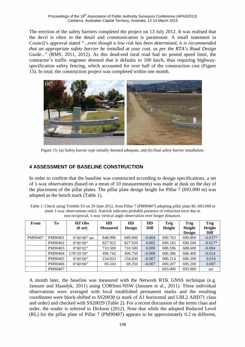
Once all pillar pours were completed, the pillars were allowed to cure for one week before the pillar plates were grouted into place. During this period, the bases around the pillar were formed and poured, and final landscaping and clearing of the site occurred. In addition, the safety barrier construction commenced. The pillar plates were installed using a low-shrinkage grouting mix. The two end pillar plates were installed first and each plate was accurately levelled. Each subsequent pillar plate was grouted and levelled and its position confirmed accurately from either end of the baseline. Brass number plates were placed in the exposed grout to avoid confusion with pillar numbering. All seven pillars were then sanded, undercoated and painted with white gloss paint to protect the PVC pipe. Finally, a stainless steel etched plaque was affixed to each pillar (Figure 14).
Figure 14: (a) Pillar ready for grouting and pillar plate, (b) pillar plate accurately centred and levelled, (c) within 2 hours pillar plate is ready to be used to confirm position of intervening pillar plates, and
(d) painting, landscaping and plaques added during the following week to complete construction.
(a) (b)
(a) (b)
(c) (d)
Proceedings of the 18th Association of Public Authority Surveyors Conference (APAS2013) Canberra, Australian Capital Territory, Australia, 12-14 March 2013
198
The erection of the safety barriers completed the project on 13 July 2012. It was realised that the devil is often in the detail and communication is paramount. A small statement in Council’s approval stated “...even though a low risk has been determined, it is recommended that an appropriate safety barrier be installed at your cost, as per the RTA’s Road Design Guide...” (RMS, 2011, 2012). As this dead-end rural road had no posted speed limit, the contractor’s traffic engineer deemed that it defaults to 100 km/h, thus requiring highway-specification safety fencing, which accounted for over half of the construction cost (Figure 15). In total, the construction project was completed within one month.
Figure 15: (a) Safety barrier type initially deemed adequate, and (b) final safety barrier installation.
4 ASSESSMENT OF BASELINE CONSTRUCTION In order to confirm that the baseline was constructed according to design specifications, a set of 1-way observations (based on a mean of 10 measurements) was made at dusk on the day of the placement of the pillar plates. The pillar plate design height for Pillar 7 (693.000 m) was adopted as the bench mark (Table 1). Table 1: Check using Trimble S3 on 29 June 2012, from Pillar 7 (PM90407) adopting pillar plate RL 693.000 m
(note 1-way observations only). Asterisk indicates probable presence of refraction error due to non-reciprocal, 1-way vertical angle observation over longer distances.
From To HZ Obs (0 set)
HD Measured
HD Design
HD Diff
Trig Height
Trig Height Design
Trig Height
Diff PM90407 PM90401 0°00’00” set 848.996 849.000 -0.004 690.763 690.800 -0.037*
PM90402 0°00’00” 827.922 827.920 0.002 690.183 690.200 -0.017* PM90403 0°00’02” 710.500 710.500 0.000 688.596 688.600 -0.004 PM90404 179°59’59” 496.742 496.750 -0.008 686.386 686.400 -0.014 PM90405 0°00’00” 234.823 234.830 -0.007 686.214 686.200 0.014 PM90406 0°00’00” 69.243 69.250 -0.007 690.207 690.200 0.007 PM90407 693.000 693.000 set
A month later, the baseline was measured with the Network RTK GNSS technique (e.g. Janssen and Haasdyk, 2011) using CORSnet-NSW (Janssen et al., 2011). Three individual observations were averaged with local established permanent marks and the resulting coordinates were block-shifted to SS20030 (a mark of A1 horizontal and LBL2 AHD71 class and order) and checked with SS20029 (Table 2). For a recent discussion of the terms class and order, the reader is referred to Dickson (2012). Note that while the adopted Reduced Level (RL) for the pillar plate of Pillar 7 (PM90407) appears to be approximately 0.2 m different,
(a) (b)
Proceedings of the 18th Association of Public Authority Surveyors Conference (APAS2013) Canberra, Australian Capital Territory, Australia, 12-14 March 2013
199
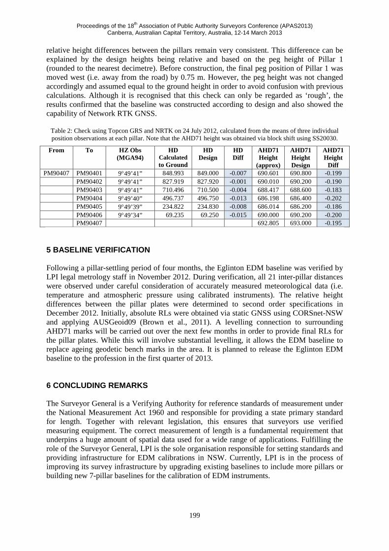
relative height differences between the pillars remain very consistent. This difference can be explained by the design heights being relative and based on the peg height of Pillar 1 (rounded to the nearest decimetre). Before construction, the final peg position of Pillar 1 was moved west (i.e. away from the road) by 0.75 m. However, the peg height was not changed accordingly and assumed equal to the ground height in order to avoid confusion with previous calculations. Although it is recognised that this check can only be regarded as ‘rough’, the results confirmed that the baseline was constructed according to design and also showed the capability of Network RTK GNSS.
Table 2: Check using Topcon GRS and NRTK on 24 July 2012, calculated from the means of three individual position observations at each pillar. Note that the AHD71 height was obtained via block shift using SS20030.
From To HZ Obs (MGA94)
HD Calculated to Ground
HD Design
HD Diff
AHD71 Height
(approx)
AHD71 Height Design
AHD71 Height
Diff PM90407 PM90401 9°49’41” 848.993 849.000 -0.007 690.601 690.800 -0.199
PM90402 9°49’41” 827.919 827.920 -0.001 690.010 690.200 -0.190 PM90403 9°49’41” 710.496 710.500 -0.004 688.417 688.600 -0.183 PM90404 9°49’40” 496.737 496.750 -0.013 686.198 686.400 -0.202 PM90405 9°49’39” 234.822 234.830 -0.008 686.014 686.200 -0.186 PM90406 9°49’34” 69.235 69.250 -0.015 690.000 690.200 -0.200 PM90407 692.805 693.000 -0.195
5 BASELINE VERIFICATION Following a pillar-settling period of four months, the Eglinton EDM baseline was verified by LPI legal metrology staff in November 2012. During verification, all 21 inter-pillar distances were observed under careful consideration of accurately measured meteorological data (i.e. temperature and atmospheric pressure using calibrated instruments). The relative height differences between the pillar plates were determined to second order specifications in December 2012. Initially, absolute RLs were obtained via static GNSS using CORSnet-NSW and applying AUSGeoid09 (Brown et al., 2011). A levelling connection to surrounding AHD71 marks will be carried out over the next few months in order to provide final RLs for the pillar plates. While this will involve substantial levelling, it allows the EDM baseline to replace ageing geodetic bench marks in the area. It is planned to release the Eglinton EDM baseline to the profession in the first quarter of 2013. 6 CONCLUDING REMARKS The Surveyor General is a Verifying Authority for reference standards of measurement under the National Measurement Act 1960 and responsible for providing a state primary standard for length. Together with relevant legislation, this ensures that surveyors use verified measuring equipment. The correct measurement of length is a fundamental requirement that underpins a huge amount of spatial data used for a wide range of applications. Fulfilling the role of the Surveyor General, LPI is the sole organisation responsible for setting standards and providing infrastructure for EDM calibrations in NSW. Currently, LPI is in the process of improving its survey infrastructure by upgrading existing baselines to include more pillars or building new 7-pillar baselines for the calibration of EDM instruments.
Proceedings of the 18th Association of Public Authority Surveyors Conference (APAS2013) Canberra, Australian Capital Territory, Australia, 12-14 March 2013
200
This paper has outlined the issues that need to be considered in the construction of a modern, state-of-the-art EDM baseline, using the newly constructed 7-pillar Eglinton EDM baseline as an example. It was shown that this process is not straightforward and requires careful consideration of various issues faced during the planning, site selection, baseline design and pillar construction stages. The Eglinton baseline in Bathurst and the Lethbridge Park baseline in western Sydney are the first two new 7-pillar EDM baselines built to improve survey infrastructure in NSW and position the State for the future. ACKNOWLEDGEMENTS Russell Commins is gratefully acknowledged for providing advice, equipment and expertise in the construction of the Tier 2 GNSS CORS style pillars. The project would not have been successful without the attention to detail provided by Hines Constructions staff involved in the pillar construction. In particular, Brad Woods is thanked for continually chasing the millimetre and taking pride in getting as close to design as possible. REFERENCES Australian Government (2013a) National Management Act 1960 (Cth),
http://www.comlaw.gov.au/Details/C2013C00075 (accessed Feb 2013).
Australian Government (2013b) National Measurement Regulations 1999 (Cth), http://www.comlaw.gov.au/Details/F2012C00400 (accessed Feb 2013).
Brown N.J., Featherstone W.E., Hu G. and Johnston G.M. (2011) AUSGeoid09: A more direct and more accurate model for converting ellipsoidal heights to AHD heights, Journal of Spatial Science, 56(1), 27-37.
Dickson G. (2012) Control Surveys: Why things are the way they are and not the way you think they should be!, Proceedings of Association of Public Authority Surveyors Conference (APAS2012), Wollongong, Australia, 19-21 March, 12-28.
Janssen V. and Haasdyk J. (2011) Assessment of Network RTK performance using CORSnet-NSW, Proceedings of International GNSS Society Symposium (IGNSS2011), Sydney, Australia, 15-17 November, 18pp.
Janssen V., Haasdyk J., McElroy S. and Kinlyside D. (2011) CORSnet-NSW: Improving positioning infrastructure for New South Wales, Proceedings of Surveying & Spatial Sciences Institute Biennial International Conference (SSSC2011), Wellington, New Zealand, 21-25 November, 395-409.
LPI (2009) Surveyor General’s Direction No. 5: Verification of Distance Measuring Equipment, http://www.lpi.nsw.gov.au/surveying/publications/surveyor_generals_directions (accessed Feb 2013).
LPI (2012) Guidelines for CORSnet-NSW Continuously Operating Reference Stations (CORS), version 1.1, available from http://www.lpi.nsw.gov.au/surveying/corsnet-nsw/education_and_research (accessed Feb 2013).
NSW Legislation (2012) Surveying and Spatial Information Regulation 2012, http://www.legislation.nsw.gov.au/maintop/view/inforce/subordleg+436+2012+cd+0+N (accessed Feb 2013).
Proceedings of the 18th Association of Public Authority Surveyors Conference (APAS2013) Canberra, Australian Capital Territory, Australia, 12-14 March 2013
201
RMS (2011) RTA supplement to Austroads Guide to Road Design Part 6 (2009): Roadside Design, Safety and Barriers, available from http://www.rta.nsw.gov.au/doingbusinesswithus/ausroadsguides/road_design.html (accessed Feb 2013).
RMS (2012) Safety barrier products accepted for use on classified roads in NSW, http://www.rta.nsw.gov.au/doingbusinesswithus/designdocuments/safety_barriers.html (accessed Feb 2013).
Rüeger J.M.R. (1984) Instructions on the verification of electro-optical short-range distance meters on subsidiary standards of length in the form of EDM calibration baselines, Report, School of Surveying, University of New South Wales, Sydney, 63pp.
Rüeger J.M.R. (1985) Traceability of electronic distance measurement to national standards, Proceedings of 27th Australian Survey Congress, Alice Springs, Australia, 23-30 March, 149-163.
Rüeger J.M.R. (1991) Legal calibration of electronic distance meters in Australia, The Australian Surveyor, 36(3), 195-212.
Rüeger J.M.R. (1996) Electronic distance measurement: An introduction (4th edition), Springer, Berlin, 300pp.
Schwendener H.R. (1972) Electronic distancers for short ranges: Accuracy and Checking procedures, Survey Review, 21(164), 273-281