Embed Size (px)
Citation preview

DOI: 10.37190/ppmp/120108
Physicochem. Probl. Miner. Process., 56(3), 2020, 513-527 Physicochemical Problems of Mineral Processing
http://www.journalssystem.com/ppmp ISSN 1643-1049
© Wroclaw University of Science and Technology
Received December 03, 2019; reviewed; accepted April 05, 2020
Improving separation efficiency of galena flotation using the Aerated Jet Flotation Cell
Si Li, Yuhua Wang, Dongfang Lu, Xiayu Zheng, Xudong Li
School of Minerals Processing & Bioengineering, Central South University, Changsha, No. 932 Lushan south Road, Hunan 410083, China
Corresponding authors: [email protected] (Yuhua Wang), [email protected] (Dongfang Lu)
Abstract: The low separation efficiency of traditional mechanical flotation cells for galena flotation primarily was caused by the low collision probability between bubbles and fine particles and high detachment probability of coarse particles. A flotation device named Aerated Jet Flotation Cell (AJFC) was adopted to improve the separation efficiency of galena flotation. Reducing bubble size and optimizing turbulence distribution were respectively confirmed as effective ways to improve fine galena-bubble collision efficiency and decrease detachment probability of coarse galena. In AJFC, micro-bubbles in diameter of 0.1-0.3 mm were generated by forcing compressed air to pass through porous high-density polyethylene tube, and high shear rate and appropriate turbulence were provided by installing a sparger with holes at the end of downcomer. The key parameters, including sparger hole number, turbulent kinetic energy (TKE), air-slurry ratio and superficial gas velocity (Jg) were optimized to achieve a desired separation performance of galena flotation. Separation efficiency of 62.54 % at a residence time of 2.25 min was achieved by AJFC, while separation efficiency of 59.12 % at a residence time of 7.5 min was achieved by mechanical flotation cell. Besides, AJFC had less loss of Pb in tailings than mechanical flotation cell in the whole particle size range, especially for fine (-25 µm) and coarse (+74 µm) size fractions.
Keywords: Aerated Jet Flotation Cell, mechanical flotation cell, fine particle, coarse particle, separation efficiency
1. Introduction
Froth flotation is regarded as an effective technique for separating different minerals from the raw ore based on their different surface hydrophobicity, which has been used in minerals beneficiation over a century (Wang et al., 2016). In addition, flotation can also be used in wastewater treatment, ink removal and plastic recycling (Prakash et al., 2018). The appropriate particle size range for froth flotation is approximately 10–100 µm. Beyond this size range, the separation efficiency will decrease notably due to the low collision efficiency between fine particles and bubbles, and then the high detachment probability of coarse particles (Miettinen et al., 2010; Kowalczuk et al., 2011; Sahbaz et al., 2012; Sobhy and Tao, 2013; Wang et al., 2016).
Along with economic development, the demand of mineral resources is unprecedentedly increasing. A new ultrafine grinding technique brings economic benefits to the processing of low-grade and fine-grained disseminated complex ore. However, large quantities of fine particles will be produced during the process of ore grinding. How to improve the separating efficiency of fine particles becomes a hard topic that should be solved (George et al., 2004; Wang et al., 2015). Studies have shown that the flotation recovery of fine particles can be improved by increasing the collision efficiency between bubbles and particles and decreasing bubble size (Trahar and Warren, 1976; Gorain et al., 1995; Ahmad et al., 2016; Li et al., 2019).

514 Physicochem. Probl. Miner. Process., 56(3), 2020, 513-527
Generally, the conventional mechanical flotation cells produce bubble size in the range of 1.2-2.7 mm using agitation impeller (Deglon et al., 2000). Lately, the flotation column was invented for generating small bubbles in diameter of 0.7-1.5 mm by using a porous plate or gas distributor (Rubio et al., 2002). In recent years, the micro-bubble technology has been widely developed. Jet flotation which used in flotation machines, such as Jameson cell, Microcell, Davcra cell and Bahr cell et al., can generate micro-bubble with diameter of 0.1–0.6 mm (Clayton et al., 1991; Prakash et al., 2018).
The collision efficiency between fine particles and bubbles in conventional mechanical flotation cells can be improved by increasing the speed of impeller, but excess energy will also decrease the stability of foam layer and increase the detachment of coarse particles, which results in the decrease of total metal recovery. Therefore, researchers turn their attention to the optimization of the energy input form and turbulence distribution by inventing new devices (Tabosa et al., 2016). Jameson cell is a typical fine particle flotation device with high efficiency (Ucurum, 2009; Yan and Jameson, 2004; Sahbaz et al., 2013). Cyclonic flotation column can intensify collision efficiency between bubbles and particles by using an inverted cone installed at the bottom of tank to generate centrifugal force (Li et al., 2012). The Concorde Cell design based on Jameson cell enhanced the collision efficiency between bubbles and particles by using impingement bowl to form the vortex ring (Jameson, 2010). A modified Jameson cell had improved the collision efficiency between bubbles and particles by using a diffuser placed at the end of the downcomer (Sahbaz et al., 2019).
The AJFC is a modified and efficient Jameson cell, and it was already used in plant for the separation of diaspore bauxite and coal mines. Moreover, it has also been proved to be an efficient device in flotation of spodumene ore in high altitude plant (Li et al., 2017). In this study, AJFC was adopted to improve the separation efficiency of galena in Fankou lead-zinc mine located in South China. Compared with the conventional mechanical flotation cells, AJFC can produce smaller bubbles by forcing compressed air to pass through the porous high density polyethylene (HDPE) tube (bubble generator), and provide high shear rate and appropriate turbulence by installing a sparger with holes at the end of downcomer. The influences of sparger hole number, air-to-slurry ratio, superficial gas velocity and turbulent kinetic energy on the flotation of galena were investigated.
2. Experimental
2.1. Materials
The chemical composition of the fine-grained galena ore from Fankou lead-zinc mine located in south China was shown in Table 1.
Table 1. Chemical composition of the lead-zinc ore
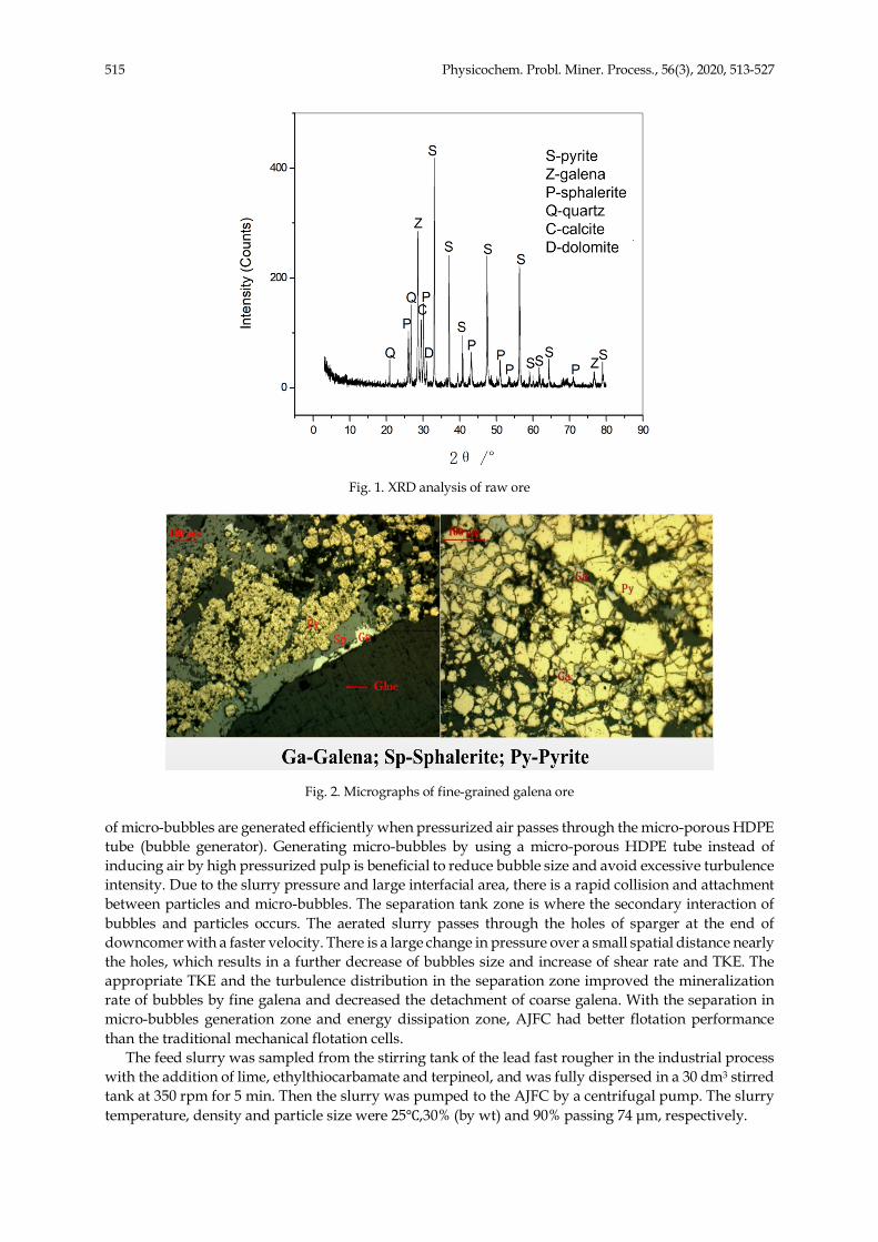
As shown in Fig. 1, XRD analysis of the sample revealed a composition of galena, pyrite, sphalerite, quartz, calcite and dolomite in raw ore. Galena presents as medium and fine size grains and is disseminated along fracture/cleavage plane of pyrite and sphalerite.
The size of galena particles varies from 10 µm to 200 µm, and the average size of galena particles is around 50 µm. There is about 10 % coarse-grained galena in ore, but the fine-grained galena with particle size less than 10 µm occupies about 35 %, which are also warped by pyrite or sphalerite as shown in Fig. 2.
2.2. Methods and procedures
2.2.1. Principle of the Aerated Jet Flotation Cell (AJFC)
Fig. 3a shows a schematic diagram of AJFC system. It consisted of downcomer zone (Fig. 3b) and separation tank zone. The downcomer zone is where the primary interaction of bubbles and particles occurs. Feed slurry is pumped into the downcomer by a centrifugal pump, meanwhile, a large number
Elements Pb Zn S SiO2 Al2O3 CaO MgO TFe others
Content (%) 4.10 7.58 19.30 17.47 4.65 12.10 4.12 21.51 9.17
515 Physicochem. Probl. Miner. Process., 56(3), 2020, 513-527
Fig. 1. XRD analysis of raw ore
Fig. 2. Micrographs of fine-grained galena ore
of micro-bubbles are generated efficiently when pressurized air passes through the micro-porous HDPE tube (bubble generator). Generating micro-bubbles by using a micro-porous HDPE tube instead of inducing air by high pressurized pulp is beneficial to reduce bubble size and avoid excessive turbulence intensity. Due to the slurry pressure and large interfacial area, there is a rapid collision and attachment between particles and micro-bubbles. The separation tank zone is where the secondary interaction of bubbles and particles occurs. The aerated slurry passes through the holes of sparger at the end of downcomer with a faster velocity. There is a large change in pressure over a small spatial distance nearly the holes, which results in a further decrease of bubbles size and increase of shear rate and TKE. The appropriate TKE and the turbulence distribution in the separation zone improved the mineralization rate of bubbles by fine galena and decreased the detachment of coarse galena. With the separation in micro-bubbles generation zone and energy dissipation zone, AJFC had better flotation performance than the traditional mechanical flotation cells.
The feed slurry was sampled from the stirring tank of the lead fast rougher in the industrial process with the addition of lime, ethylthiocarbamate and terpineol, and was fully dispersed in a 30 dm3 stirred tank at 350 rpm for 5 min. Then the slurry was pumped to the AJFC by a centrifugal pump. The slurry temperature, density and particle size were 25℃,30% (by wt) and 90% passing 74 µm, respectively.

516 Physicochem. Probl. Miner. Process., 56(3), 2020, 513-527
Fig. 3. Diagrammatic sketch of the AJFC (a) and its downcomer (b)
2.2.2. Slurry preparation and parameter design
Because the AJFC is a modified Jameson cell, so its parameters were set up based on the parameters of Jameson cell, as shown in Table 2. Here, the lower jet velocity(9.44-12.56 m/s) was used to decrease the detachment probability of coarse particles (Cowburn et al., 2006). The lower Jg (4.4-7.9 mm/s) was also chosen for achieving a higher concentrate grade (Harbort et al., 2003). The tank resident time was adopted based on Harbort’s research results by using a small tank size in this study (Harbort et al., 2003).
Table 2. Parameters of Jameson cell and AJFC
Machine Jet velocity (m/s) Jg (mm/s) Air-slurry ratio Tank resident time (min)
Jameson cell 11.1-18.1 4.0-12 0.79-1.89 1.5-4.1
AJFC 9.44-12.56 4.4-7.9 0.9-1.8 1.25-2.25
After determining the appropriate parameter range of AJFC, the optimal parameters of sparger hole number, TKE, air-slurry ratio and superficial gas velocity (Jg) on the flotation performance of AJFC were then determined by different experiments on hole number, hole diameter, air flow rate and tank diameter. The slurry flow rate, underflow rate, separation tank height, and downcomer immersing depth were kept constant as 2 dm3/min, 1.5 dm3/min, 400 mm and 335 mm, respectively. If not specified, the tank diameter is 100 mm. The main technical parameters of AJFC used in flotation experiments are shown in Table 3. It is noteworthy that, in sparger hole number experimental, the hole diameter of one hole, two holes and three holes are 2 mm, 1.5 mm and 1.2 mm, respectively. So, the jet velocity of single hole, double holes and three holes with slurry flow rate at 2 dm3/min are 10.61 m/s, 9.44 m/s and 9.83 m/s, respectively.
2.3. Bubble size measurement
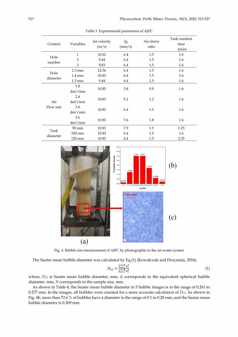
Bubble size measurements of AJFC were done in the water-air system under the following conditions: air flow rate 3 dm3/min, water flow rate 2 dm3/min, double holes with a diameter of 1.4 mm, separation tank diameter 120 mm, separation tank height 400 mm, downcomer immersing depth 335 mm. The dosage of terpineol is 40 g/m3 and the temperature is about 25 ℃. The bubble images were photographed from the rectangle area in Fig. 4a and shown in Fig. 4c. Five bubble images were photographed at 10-second intervals, and bubble size was counted by the software of IMAGE PRO PLUS 6.0.
0DQXVFULSW�ERG\'RZQORDG�VRXUFH�ILOH�������0%�
5
Fig. 3. Diagrammatic sketch of the AJFC (a) and its downcomer (b)
2.2.2 Slurry preparation and parameter design
The feed slurry was sampled from the stirring tank of the lead fast rougher in the
industrial process with the addition of lime, ethylthiocarbamate and terpineol, and was fully
dispersed in a 30 dm3 stirred tank at 350 rpm for 5 min. Then the slurry was pumped to the
AJFC by a centrifugal pump. The slurry temperature, density and particle size were 25℃,30%(by Wt) and 90% passing 74 μm, respectively.
Because the AJFC is a modified Jameson cell, so its parameters were set up based on the
parameters of Jameson cell, as shown in Table 2. Here, the lower jet velocity(9.44-12.56 m/s) was used to decrease the detachment probability of coarse particles (Cowburn et al., 2006).
The lower Jg (4.4-7.9 mm/s) was also chosen for achieving a higher concentrate grade (Harbort et al., 2003). The tank resident time was adopted based on Harbort’s research results
by using a small tank size in this study (Harbort et al., 2003).
Table 2. Parameters of Jameson cell and AJFC
Machine Jet velocity (m/s) Jg (mm/s) Air-slurry ratio Tank resident time (min)
Jameson cell 11.1-18.1 4.0-12 0.79-1.89 1.5-4.1
AJFC 9.44-12.56 4.4-7.9 0.9-1.8 1.25-2.25
After determining the appropriate parameter range of AJFC, the optimal parameters of
sparger hole number, TKE, air-slurry ratio and superficial gas velocity ( Jg) on the flotation performance of AJFC were then determined by different experiments on hole number, hole
diameter, air flow rate and tank diameter. The slurry flow rate, underflow rate, separation
tank height, and downcomer immersing depth were kept constant as 2 dm3/min, 1.5
dm3/min, 400 mm and 335 mm, respectively. If not specified, the tank diameter is 100 mm. The main technical parameters of AJFC used in flotation experiments are shown in Table 3. It
112
113
114
115
116
117
118
119
120
121
122
123
124
125
126
127
128
129
130
131
132
133
134
135
136
517 Physicochem. Probl. Miner. Process., 56(3), 2020, 513-527
Table 3. Experimental parameters of AJFC
Content Variables Jet velocity
(m/s) Jg
(mm/s) Air-slurry
ratio
Tank resident time
(min)
Hole number
1 10.61 6.4 1.5 1.6 2 9.44 6.4 1.5 1.6 3 9.83 6.4 1.5 1.6
Hole diameter
1.3 mm 12.56 6.4 1.5 1.6 1.4 mm 10.83 6.4 1.5 1.6 1.5 mm 9.44 6.4 1.5 1.6
Air Flow rate
1.8 dm3/min
10.83 3.8 0.9 1.6
2.4 dm3/min
10.83 5.1 1.2 1.6
3.0 dm3/min
10.83 6.4 1.5 1.6
3.6 dm3/min
10.83 7.6 1.8 1.6
Tank diameter
90 mm 10.83 7.9 1.5 1.25 100 mm 10.83 6.4 1.5 1.6 120 mm 10.83 4.4 1.5 2.25
Fig. 4. Bubble size measurement of AJFC by photographic in the air-water system
The Sauter mean bubble diameter was calculated by Eq.(1) (Kowalczuk and Drzymala, 2016).
𝐷#$ =∑ '(
)(*+(*,
∑ '(-(*+
(*, (1)
where, D32 is Sauter mean bubble diameter, mm, di corresponds to the equivalent spherical bubble diameter, mm, N corresponds to the sample size, mm.
As shown in Table 4, the Sauter mean bubble diameter in 5 bubble images is in the range of 0.261 to 0.277 mm. In the images, all bubbles were counted for a more accurate calculation of D32. As shown in Fig. 4b, more than 72.6 % of bubbles have a diameter in the range of 0.1 to 0.28 mm, and the Sauter mean bubble diameter is 0.269 mm.
518 Physicochem. Probl. Miner. Process., 56(3), 2020, 513-527
Table 4. The Sauter mean bubble diameter of 5 images
Time (s) 10 20 30 40 50
Bubble number 215 242 251 222 250
D32 (mm) 0.277 0.275 0.261 0.267 0.264
2.4. Separation efficiency equation
To evaluate the performance of AJFC and mechanical flotation cells in lead fast rougher, the equation of separation efficiency shown as follow was used.
𝐸 = (012)(410)0(412)(510/47)
× 100% (2)
where, E is separation efficiency, %, α is grade of raw ore, %, β is grade of concentrate, %, θ is grade of tailing, %, βm is lead content of pure galena (86.62), %.
2.5. CFD simulations
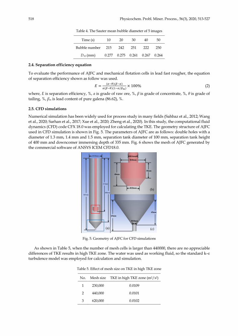
Numerical simulation has been widely used for process study in many fields (Sahbaz et al., 2012; Wang et al., 2020; Sarhan et al., 2017; Xue et al., 2020; Zheng et al., 2020). In this study, the computational fluid dynamics (CFD) code CFX 18.0 was employed for calculating the TKE. The geometry structure of AJFC used in CFD simulation is shown in Fig. 5. The parameters of AJFC are as follows: double holes with a diameter of 1.3 mm, 1.4 mm and 1.5 mm, separation tank diameter of 100 mm, separation tank height of 400 mm and downcomer immersing depth of 335 mm. Fig. 6 shows the mesh of AJFC generated by the commercial software of ANSYS ICEM CFD18.0.
Fig. 5. Geometry of AJFC for CFD simulations
As shown in Table 5, when the number of mesh cells is larger than 440000, there are no appreciable differences of TKE results in high TKE zone. The water was used as working fluid, so the standard k–ε turbulence model was employed for calculation and simulation.
Table 5. Effect of mesh size on TKE in high TKE zone
No. Mesh size TKE in high TKE zone (m2/s2)
1 230,000 0.0109
2 440,000 0.0101
3 620,000 0.0102

519 Physicochem. Probl. Miner. Process., 56(3), 2020, 513-527
The boundary conditions were given in Table 6, and no slip conditions were set on walls. The SIMPLE algorithm was used for pressure-velocity coupling with the second order discretization scheme.
Table 6. Boundary conditions
Name Type Unit Value
Hole inlet Mass flow rate Kg/s 0.033
Down outlet Mass flow rate Kg/s 0.025
Up outlet Gauge pressure Pa 0
Fig. 6. Mesh of AJFC for CFD simulations
3. Results and discussion
3.1. Effects of sparger hole number
Under the premise of the same total sectional area of the hole, the hole number of sparger is an important factor determining the turbulent and bubble distribution and has an obvious effect on the flotation performance of AJFC. To determine the optimum hole number, spargers with different hole numbers were tested and their appearances were shown in Fig. 7. Here, the hole diameter of one hole, two holes and three holes are 2 mm, 1.5 mm and 1.2 mm, respectively.
Fig. 7. Spargers with different number of holes
According to the results presented in Fig. 8, the hole number shows a significant effect on the Pb recovery and grade of concentrate. Both the recovery and grade in concentrate increased with the increase of the hole number. A better flotation performance was achieved using sparger with double holes. However, further increasing the number of the hole showed no obvious improvement of flotation performance. As shown in Fig. 9, the distribution of bubble is more uniform while using sparger with

520 Physicochem. Probl. Miner. Process., 56(3), 2020, 513-527
two or three holes. Furthermore, the distribution of bubble is very similar for spargers with double and three holes.
Fig. 8. Effect of hole number on grade, recovery and separation efficiency of Pb
Fig. 9. Effect of hole number on distribution of bubble in water
3.2. Effects of turbulent kinetic energy (TKE)
Turbulent kinetic energy (TKE) is an important parameter affecting the collision efficiency between particles and bubbles in froth flotation. The area-weighted average TKE on the cross-section of the hole was calculated and used in this study. Here, the number of holes with different diameter is 2. Fig. 10 shows the influences of TKE on the concentrate grade and recovery of Pb. It can be found that the concentrate grade and recovery increased with the increase of TKE from 0.281 m2/s2 to 0.363 m2/s2. However, the further increase of the TKE caused the slight increase of Pb recovery but the slight decrease of Pb grade. As shown in Fig. 11, the distribution of TKE in AJFC was divided into high TKE zone (below the sparger) and low TKE zone (above the sparger). When the diameters of double holes are 1.3 mm, 1.4 mm and 1.5 mm, the calculated area-weighted average TKE on the cross-section of hole are 0.475 m2/s2, 0.363 m2/s2 and 0.281 m2/s2, respectively. The high TKE zone near hole provides enough energy for the collision between bubbles and particles. However, the volume average TKE of three different holes in high TKE zone are only 0.0144 m2/s2, 0.0129 m2/s2 and 0.0118 m2/s2, respectively. The appropriate volume average TKE of mechanical flotation cell is about 0.18 m2/s2, which is larger than that of AJFC, so lower average TKE in the tank of AJFC is beneficial to reduce the detachment of coarse particles from bubbles (Jameson and Emer, 2019).

521 Physicochem. Probl. Miner. Process., 56(3), 2020, 513-527
Fig. 10. Influence of TKE on grade, recovery and separation efficiency of Pb
Fig. 11. Distribution of TKE in AJFC with double holes in different diameter
To further understand the changes of TKE in the tank, two yellow lines (r/R=0.5, Y=0 mm; Z=65 mm, Y=0 mm) shown in Fig. 12(a) were selected to analyze the TKE distribution under the above test conditions. As shown in Fig. 12(b), only a zone in rang of z=50 mm to z=70 mm near the sparger holes has high TKE, but it only occupies 5 % of all axial zone. As shown in Fig. 12(c), there are also high TKE zones near the sparger holes, and the TKE decreased as the increase of hole diameter from 1.3 mm to 1.5 mm.
3.3 Effects of air-slurry ratio
The air-slurry ratio is the ratio of the air flowrate to slurry flowrate, which affects the gas holdup and bubble size, and consequently flotation performance of equipment (Gursoy and Oteyaka 2015). Based on the working principle of AJFC, when the air-slurry ratio is too small, it is difficult to press air to pass through the porous HDPE tube to form bubbles, and even the slurry may enter into the air system and cause equipment damage. However, an excessive air-slurry ratio will generate a lot of large bubbles and cause a discontinuous jet at the hole of sparger, which results in the unsteady running of AJFC.

522 Physicochem. Probl. Miner. Process., 56(3), 2020, 513-527
In this study, the slurry flow rate was held constant as 2 dm3/min by adjusting the speed of the centrifugal pump to keep the residence time to be constant in the downcomer and tank. Fig. 13 shows the effect of air-slurry ratio on Pb grade and recovery. Here, the number and diameter of holes are 2 and 1.4 mm,respectively. It can be seen from Fig. 13 that the Pb grade and recovery of concentrate increased as the air-slurry ratio increased from 0.9 to 1.5, but decreased when air-slurry ratio increased from 1.5 to 1.8. In other words, the increase of air-slurry ratio within an appropriate range can obtain appropriate bubble surface area flux, which can improve the Pb grade and recovery at the same time. Further increasing the air-slurry ratio will decrease bubble surface area flux due to the large bubble size after the air and pulp entered into the tank from sparger (Gursoy and Oteyaka, 2015), and then leads to the decrease of Pb grade and recovery in concentrate.
Fig. 12. TKE distribution in tank
Fig. 13. Influence of air-slurry ratio on grade, recovery and separation efficiency of Pb
3.4 Effects of superficial gas velocity
Superficial gas velocity (Jg) is the ratio of the air flowrate to the cross-sectional area of the tank, and it was defined as the upward velocity of air in the flotation tank. Superficial gas velocity is also closely linked to the bubble surface area flux, which has a significant influence on the flotation rate. The relationship between the bubble surface area flux (Sb) and Jg is given as follow (Şahbaz et al. ,2008; Matis,1995):

523 Physicochem. Probl. Miner. Process., 56(3), 2020, 513-527
𝑆= =>?@'A
(3)
where, Sb is surface area flux, s-1, Jg is superficial gas velocity, mm/s, db is the diameter of bubbles, mm. Based on the data in Table 7, the mechanical flotation cell and flotation column have bigger Jg and
bubble size. Jameson cell and AJFC have smaller Jg and bubble size, but the latter has higher Sb value.
Table 7. Jg of different flotation devices(Vera et al., 1999; Şahbaz et al. ,2008; Matis,1995)
Technology Mechanical flotation cells Flotation Column Jameson Cell AJFC Jg (mm/s) 20 19 14 4.4
Bubble size (mm) 1.3 2.2 0.95 0.26 Sb (s-1) 92.31 51.82 88.42 101.54
Fig. 14 shows the effect of Jg on Pb grade and recovery of concentrate. Here, the number and diameter of holes are 2 and 1.4 mm, respectively. The recovery of Pb is almost unchanged but the Pb grade reduced markedly as the increase of Jg from 4.4 mm/s to 7.9 mm/s. The reason for this result is that the decrease of tank diameter from 120 mm to 90 mm causes the decrease of tank resident time from 2.25 min to 1.25 min, and then the decrease of Pb grade in concentrate. Besides, Sb increased with the increase of Jg, but higher Sb can also cause higher gangue entrainment in froth production, which results in the decrease of concentrate grade. It is noteworthy that concentrate grade decreased as Jg decreased (caused by the decrease of tank diameter) at the optimum air-slurry ratio of 1.5. If the air-slurry ratio is smaller than 1.5 (as shown in Fig. 13), concentrate grade increased as Jg increased (caused by the increase of air flowrate).
Fig.14. Influence of Jg on grade, recovery and separation efficiency of Pb
3.5. Comparative experiment between AJFC and mechanical flotation cell
For comparing flotation performances of AJFC and mechanical flotation cell, the comparative experiments between one AJFC and six mechanical flotation cells were done and repeated five times in lead fast rougher. The optimized parameters of AJFC are: air-slurry ratio at 1.5 (air flowrate is 3 dm3/min and slurry flowrate is 2 dm3/min), Jg at 4.4 mm/s (separation tank diameter of 120 mm), TKE at 0.363 m2/s2 (double holes with diameter of 1.4 mm), separation tank height of 400 mm, downcomer immersing depth of 335 mm. There are six mechanical flotation cells (XCF-4) running steadily in lead fast rougher in workshop.
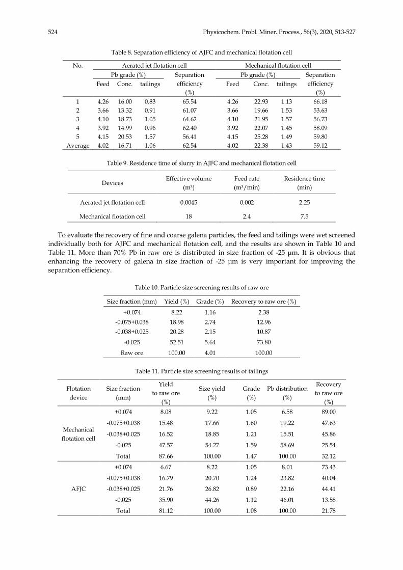
As shown in Table 8 and Table 9, the average Pb grade and recovery of tailings for AJFC are respectively 1.06 % and 16.71 %, but those of tailings for mechanical flotation cell are respectively 1.43 % and 22.38 %. The separation efficiencies of AJFC and mechanical flotation cell are 62.54 % and 59.12 %, with the residence times of 2.25 min and 7.5 min, respectively.
524 Physicochem. Probl. Miner. Process., 56(3), 2020, 513-527
Table 8. Separation efficiency of AJFC and mechanical flotation cell
No. Aerated jet flotation cell Mechanical flotation cell Pb grade (%) Separation
efficiency (%)
Pb grade (%) Separation efficiency
(%) Feed Conc. tailings Feed Conc. tailings
1 4.26 16.00 0.83 65.54 4.26 22.93 1.13 66.18 2 3.66 13.32 0.91 61.07 3.66 19.66 1.53 53.63 3 4.10 18.73 1.05 64.62 4.10 21.95 1.57 56.73 4 3.92 14.99 0.96 62.40 3.92 22.07 1.45 58.09 5 4.15 20.53 1.57 56.41 4.15 25.28 1.49 59.80
Average 4.02 16.71 1.06 62.54 4.02 22.38 1.43 59.12
Table 9. Residence time of slurry in AJFC and mechanical flotation cell
Devices Effective volume
(m3) Feed rate (m3/min)
Residence time (min)
Aerated jet flotation cell 0.0045 0.002 2.25
Mechanical flotation cell 18 2.4 7.5
To evaluate the recovery of fine and coarse galena particles, the feed and tailings were wet screened individually both for AJFC and mechanical flotation cell, and the results are shown in Table 10 and Table 11. More than 70% Pb in raw ore is distributed in size fraction of -25 µm. It is obvious that enhancing the recovery of galena in size fraction of -25 µm is very important for improving the separation efficiency.
Table 10. Particle size screening results of raw ore
Size fraction (mm) Yield (%) Grade (%) Recovery to raw ore (%)
+0.074 8.22 1.16 2.38 -0.075+0.038 18.98 2.74 12.96 -0.038+0.025 20.28 2.15 10.87
-0.025 52.51 5.64 73.80
Raw ore 100.00 4.01 100.00
Table 11. Particle size screening results of tailings
Flotation device
Size fraction (mm)
Yield to raw ore
(%)
Size yield (%)
Grade (%)
Pb distribution (%)
Recovery to raw ore
(%)
Mechanical flotation cell
+0.074 8.08 9.22 1.05 6.58 89.00
-0.075+0.038 15.48 17.66 1.60 19.22 47.63
-0.038+0.025 16.52 18.85 1.21 15.51 45.86
-0.025 47.57 54.27 1.59 58.69 25.54
Total 87.66 100.00 1.47 100.00 32.12
AFJC
+0.074 6.67 8.22 1.05 8.01 73.43
-0.075+0.038 16.79 20.70 1.24 23.82 40.04
-0.038+0.025 21.76 26.82 0.89 22.16 44.41
-0.025 35.90 44.26 1.12 46.01 13.58
Total 81.12 100.00 1.08 100.00 21.78
525 Physicochem. Probl. Miner. Process., 56(3), 2020, 513-527
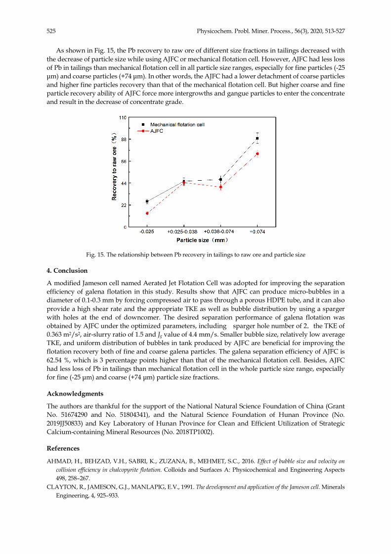
As shown in Fig. 15, the Pb recovery to raw ore of different size fractions in tailings decreased with the decrease of particle size while using AJFC or mechanical flotation cell. However, AJFC had less loss of Pb in tailings than mechanical flotation cell in all particle size ranges, especially for fine particles (-25 µm) and coarse particles (+74 µm). In other words, the AJFC had a lower detachment of coarse particles and higher fine particles recovery than that of the mechanical flotation cell. But higher coarse and fine particle recovery ability of AJFC force more intergrowths and gangue particles to enter the concentrate and result in the decrease of concentrate grade.
Fig. 15. The relationship between Pb recovery in tailings to raw ore and particle size
4. Conclusion
A modified Jameson cell named Aerated Jet Flotation Cell was adopted for improving the separation efficiency of galena flotation in this study. Results show that AJFC can produce micro-bubbles in a diameter of 0.1-0.3 mm by forcing compressed air to pass through a porous HDPE tube, and it can also provide a high shear rate and the appropriate TKE as well as bubble distribution by using a sparger with holes at the end of downcomer. The desired separation performance of galena flotation was obtained by AJFC under the optimized parameters, including sparger hole number of 2,the TKE of 0.363 m2/s2, air-slurry ratio of 1.5 and Jg value of 4.4 mm/s. Smaller bubble size, relatively low average TKE, and uniform distribution of bubbles in tank produced by AJFC are beneficial for improving the flotation recovery both of fine and coarse galena particles. The galena separation efficiency of AJFC is 62.54 %, which is 3 percentage points higher than that of the mechanical flotation cell. Besides, AJFC had less loss of Pb in tailings than mechanical flotation cell in the whole particle size range, especially for fine (-25 µm) and coarse (+74 µm) particle size fractions.
Acknowledgments
The authors are thankful for the support of the National Natural Science Foundation of China (Grant No. 51674290 and No. 51804341), and the Natural Science Foundation of Hunan Province (No. 2019JJ50833) and Key Laboratory of Hunan Province for Clean and Efficient Utilization of Strategic Calcium-containing Mineral Resources (No. 2018TP1002).
References
AHMAD, H., BEHZAD, V.H., SABRI, K., ZUZANA, B., MEHMET, S.C., 2016. Effect of bubble size and velocity on collision efficiency in chalcopyrite flotation. Colloids and Surfaces A: Physicochemical and Engineering Aspects 498, 258–267.
CLAYTON, R., JAMESON, G.J., MANLAPIG, E.V., 1991. The development and application of the Jameson cell. Minerals Engineering, 4, 925–933.
526 Physicochem. Probl. Miner. Process., 56(3), 2020, 513-527
COWBURN, J., HARBORT, G., MANLAPIG, E., POKRAJCIC, Z., 2006. Improving the recovery of coarse coal particles in a Jameson cell. Minerals Engineering ,19, 609–618.
DEGLON, D.A., EGYA-MENSAH, D., FRANZIDIS, J.P., 2000. Review of hydrodynamics and gas dispersion in flotation cells on South African platinum concentrators. Minerals Engineering, 13, 235–244.
GORAIN, B., FRANZIDIS, J.P., MANLAPIG, E., 1995. Studies on impeller type impeller speed and air flow rate in an industrial scale flotation cell — Part 1: Effect on bubble size distribution. Minerals Engineering, 8, 615–635.
GEORGE, P., NGUYEN, A.V., JAMESON, G.J., 2004. Assessment of true flotation and entrainment in the flotation of submicron particles by fine bubbles. Minerals Engineering 17,847–853.
GURSOY, Y.H., OTEYAKA, B., 2015. Effects of air-to-pulp ratio and bias factor on flotation of complex Cu-Zn sulphide ore in the Jameson cell. Physicochemical Problems of Mineral Processing, 51, 511–519.
HARBORT, G., DEBONO, S., CARR, D., LAWSON, V., 2003. Jameson cell fundamentals - A revised perspective. Minerals Engineering, 16, 1091–1101.
JAMESON, G.J., 2010. New directions in flotation machine design. Minerals Engineering, 23, 835–841. JAMESON, G.J., EMER, C., 2019. Coarse chalcopyrite recovery in a universal froth flotation machine. Minerals
Engineering, 134, 118–133. KOWALCZUK, P.B., SAHBAZ, O., DRZYMALA, J., 2011. Maximum size of floating particles in different flotation cells.
Minerals Engineering, 24, 766–771. KOWALCZUK, P.B., DRZYMALA, J., 2016. Physical meaning of the Sauter mean diameter of spherical particulate matter.
Particulate Science and Technology, 34, 645–647. LI, G., CAO, Y., LIU, J., WANG, D., 2012. Cyclonic flotation column of siliceous phosphate ore, International Journal of
Mineral Processing, 110–111, 6–11. LI, S, LU, D.F., ZHENG, X.Y., CHEN, X.H., ZHENG, X.Y, LI, X.D, CHU, H.R, WANG, Y.H., 2017. Industrial
application of a modified pilot-scale Jameson cell for the flotation of spodumene ore in high altitude area. Powder Technology, 320, 358–361
LI, Y., LI, J., CHEN, P., CHEN, J., SHEN, L., ZHU, X., CHENG, G., 2019. The effect of ultra-fine coal on the flotation behavior of silica in subbituminous coal reverse flotation. Powder Technology, 342, 457–463.
MIETTINEN, T., RALSTON, J., FORNASIERO, D., 2010. The limits of fine particle flotation. Minerals Engineering, 23, 420–437.
MATIS, K.A., Flotation Science and Engineering. 1995.1st Edition., Marcel Dekker, New York. PRAKASH, R., MAJUMDER, S.K., SINGH, A., 2018. Flotation technique: Its mechanisms and design parameters.
Chemical Engineering and Processing - Process Intensification, 127, 249–270. RUBIO, J., SOUZA, M., SMITH, R., 2002. Overview of flotation as a wastewater treatment technique. Minerals
Engineering, 15, 139–155. SAHBAZ, O., OTEYAKA, B., KELEBEK, S., UCAR, A., DEMIR, U., 2008. Separation of unburned carbonaceous matter
in bottom ash using Jameson cell. Separation and Purification Technology, 62, 103–109. SAHBAZ, O., ERCETIN, U., OTEYAKA, B., 2012. Determination of turbulence and upper size limit in jameson flotation
cell by the use of computational fluid dynamic modelling. Physicochemical Problems of Mineral Processing, 48, 533–544.
SAHBAZ, O., UCAR, A., OTEYAKA, B., 2013. Velocity gradient and maximum floatable particle size in the jameson cell. Minerals Engineering, 41, 79–85.
SAHBAZ, O., UCAR, A., OTEYAKA, B., 2019. Downcomer modification in the Jameson cell and its effects on coarse particle flotation. Particulate Science and Technology, 37, 510–515.
SARHAN A.R., NASER, J., BROOKS, G., 2017. CFD analysis of solid particles properties effect in three-phase flotation column. Separation and Purification Technology, 185, 1–9.
SOBHY, A., TAO, D., 2013. Nanobubble column flotation of fine coal particles and associated fundamentals. International Journal of Mineral Processing, 124, 109–116.
TABOSA, E., RUNGE, K., HOLTHAM, P., 2016. The effect of cell hydrodynamics on flotation performance. International Journal of Mineral Processing, 156, 99–107.
TASDEMIR, A., TASDEMIR, T., OTEYAKA, B., 2007. The effect of particle size and some operating parameters in the separation tank and the downcomer on the Jameson cell recovery. Minerals Engineering, 20, 1331–1336.
TRAHAR, W.J., WARREN, L.J., 1976. The flotability of very fine particles — A review. International Journal of Mineral Processing, 3, 103–131.
527 Physicochem. Probl. Miner. Process., 56(3), 2020, 513-527
UCURUM, M., 2009. Influences of Jameson flotation operation variables on the kinetics and recovery of unburned carbon. Powder Technology, 191, 240–246.
VERA, M.A., FRANZIDIS, J.P., MANLAPIG, E.V., 1999. JKMRC high bubble surface area flux flotation cell. Minerals Engineering, 12, 477–484.
WANG, L., PENG, Y., RUNGE, K., BRADSHAW, D., 2015. A review of entrainment: Mechanisms, contributing factors and modelling in flotation. Minerals Engineering, 70, 77–91
WANG, G., NGUYEN, A.V., MITRA, S., JOSHI, J.B., JAMESON G.J., EVANS, G.M., 2016. A review of the mechanisms and models of bubble-particle detachment in froth flotation. Separation and Purification Technology, 170, 155–172.
WANG, Y.H., XUE Z.X., ZHENG X.Y., LU D.F., SUN Z.X., 2020. Matching relation between matrix aspect ratio and applied magnetic induction for maximum particle capture in transversal high gradient magnetic separation. Minerals Engineering, 151, 106316.
XUE, Z.X., WANG Y.H., ZHENG X.Y., LU D.F., LI X.D., 2019. Particle capture of special cross-section matrices in axial high gradient magnetic separation: A 3D simulation. Separation and Purification Technology, 237, 116375.
YAN Y.D., JAMESON G.J., 2004. Application of the Jameson Cell technology for algae and phosphorus removal from maturation ponds. International Journal of Mineral Processing, 73, 23–28.
ZHENG, X.Y., SUN, Z.X., WANG, Y.H., LU, D.F., XUE, Z.X.Y., 2020. Matching relation between matrix aspect ratio and applied induction for maximum particle capture in longitudinal high gradient magnetic separation. Separation and Purification Technology,241,116687.