Embed Size (px)
Citation preview
Improving H2O Measurement in Catalytic Reformer Hydrogen Recycle Streams
On-line, real-time moisture measurements in catalytic reformer hydrogen recycle gas streams help refineries assess catalyst condition and improve process control during normal operation, in-situ catalyst regeneration and dry down.
By: W. Gary Engelhart, Product Line Marketing Manager at SpectraSensors
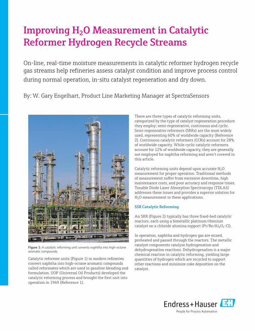
Catalytic reformer units (Figure 1) in modern refineries convert naphtha into high-octane aromatic compounds called reformates which are used in gasoline blending and formulation. UOP (Universal Oil Products) developed the catalytic reforming process and brought the first unit into operation in 1949 (Reference 1).
There are three types of catalytic reforming units, categorized by the type of catalyst regeneration procedure they employ: semi-regenerative, continuous and cyclic. Semi-regenerative reformers (SRRs) are the most widely used, representing 60% of worldwide capacity (Reference 2). Continuous catalytic reformers (CCRs) account for 28% of worldwide capacity. While cyclic catalytic reformers account for 12% of worldwide capacity, they are generally not employed for naphtha reforming and aren’t covered in this article.
Catalytic reforming units depend upon accurate H2O measurement for proper operation. Traditional methods of measurement suffer from excessive downtime, high maintenance costs, and poor accuracy and response times. Tunable Diode Laser Absorption Spectroscopy (TDLAS) addresses these issues and provides a superior solution for H2O measurement in these applications.
SSR Catalytic Reforming
An SRR (Figure 2) typically has three fixed-bed catalytic reactors, each using a bimetallic platinum/rhenium catalyst on a chloride alumina support (Pt/Re/Al2O3-Cl).
In operation, naphtha and hydrogen gas are mixed, preheated and passed through the reactors. The metallic catalyst components catalyze hydrogenation and dehydrogenation reactions. Dehydrogenation is a major chemical reaction in catalytic reforming, yielding large quantities of hydrogen which are recycled to support other reactions and minimize coke deposition on the catalyst.
Figure 1: A catalytic reforming unit converts naphtha into high-octane aromatic compounds.

2
Water along with a chloride compound is continuously injected to chlorinate the alumina and maintain acid sites needed to perform hydrocracking, isomerization and cyclization conversion reactions. All these reforming reactions occur in series and concurrently with dehydrogenation and isomerization in the first reactor; and dehydrogenation, isomerization, hydrocracking and cyclization in the second and third reactors.
The hot reaction products exiting the third reactor are passed through a heat exchanger to a gas separator. Hydrogen from the separator is directed to the hydrogen recycle compressor to feed the reforming process. The liquid phase in the separator is transferred to a fractionation column called a stabilizer. The liquid bottoms in the stabilizer are high-octane reformate destined for gasoline blending. The overhead off-gas from the stabilizer is sent to the refinery’s gas processing unit to recover an LPG mix of propane and butane.
CCR Catalytic Reforming
A CCR (Figure 3) typically has a three-stage stacked reactor and a separate, external catalyst regenerator. In a CCR, a portion of the catalyst is extracted from the bottom of the reactor stack and transferred to the regenerator. Inside the regenerator, coke deposits on the catalyst are burned off, and the
catalyst is oxy-chlorinated and dried sequentially in separate zones. Following re-activation with hydrogen, the catalyst is returned to the top reactor in the CCR stack. This process regenerates the catalyst approximately every three days.
The reformer and regeneration sections operate independently in a CCR, so the reformer is not exposed to the harsh regeneration conditions and corrosion issues encountered in an SRR. CCR units can operate continuously for a period of three to six years without a shutdown for catalyst replacement. An SRR must be completely shut down about once every 6 to 24 months for catalyst regeneration, halting production of reformate and hydrogen gas used in other refinery operations. Depending upon the capacity of the refinery and its slate of products, the financial loss from shutdown of an SRR can exceed $1 million per day.
Excess Water Adversely Affects Operations
Accurate measurement and control of moisture is a technical challenge in the operation of catalytic reformer units. During normal operation the moisture content of the reactor feed is controlled at a low level (5 to 50 ppm). Refineries try to avoid excessive moisture levels because too much moisture on the catalyst strips chloride from the catalyst and reduces catalyst cracking/isomerization activity. Adding more chloride to make up for this loss results in problems downstream, such as acid attack and corrosion.
Chlorides stripped from the catalyst may react to form HCl that carries through the effluent train, regeneration system, stabilizer tower, debutanizer tower and feed/preheat exchangers. HCl-containing vapors can migrate through the gas plant fractionation section, resulting in mix point or acid dew point corrosion. Formation and precipitation of ammonium chloride (NH4Cl) salt deposits is another corrosion problem encountered when high temperature streams containing NH3 and HCl are cooled.
Catalyst activity in an SRR gradually decreases over time as coke is deposited on the catalyst and chloride is lost. The catalyst beds in an SRR are periodically regenerated to restore catalyst activity, with the SRR taken off line and regeneration performed by in-situ oxidation.
Figure 2 - Semi-regenerative catalytic reformer.
Figure 3 - Continuous catalytic reformer.
3
Regeneration involves depressurizing each reactors and purging it with nitrogen to remove hydrocarbons. Air is then introduced to perform high temperature oxidation and burn the coke deposits off the catalyst.
Oxidation produces water, which leaches chloride from the catalyst. After the oxidation step, a chlorinated organic compound is introduced to restore the chloride level necessary for catalyst activity. A hydrogen purge is then performed to reduce the catalyst metal oxides formed during coke burn-off to an active state.
Hydrogen is recirculated through the reformer unit to reduce the moisture level prior to restarting regular operation. The water level in the hydrogen recycle gas stream is monitored during this drying cycle to help gauge when conditions have reached a level sufficient to restart the SRR unit. The total regeneration process can take up to 15 days depending on the associated maintenance required.
Some of the problems arising from elevated H2O levels in catalytic reformer units are summarized in Table 1.
Monitoring moisture concentration during regeneration and subsequent drying of the catalyst upon reintroduction of the feed gas is important for optimizing catalyst performance and life. During regeneration, moisture is measured at higher levels (up to 1,000 ppm) to monitor the progress of catalyst decoking. The expensive catalyst can be regenerated three or four times before it must be replaced. The spent catalyst is returned to the manufacturer to recover the platinum or rhenium metals. One of the ways to monitor H2O levels for optimal catalyst activity during in-situ regeneration is by measuring the water content in SRR hydrogen recycle gas (see Figure 2).
The equipment repair and/or replacement cost, labor cost, and lost revenue from shut down of a catalytic reformer unit due to elevated H2O levels and corrosion underscore the importance of moisture measurement and control. An example of the costs incurred by a U.S. West Coast refinery to deal with corrosion damage from elevated H2O levels in their SRR are shown in Table 2.
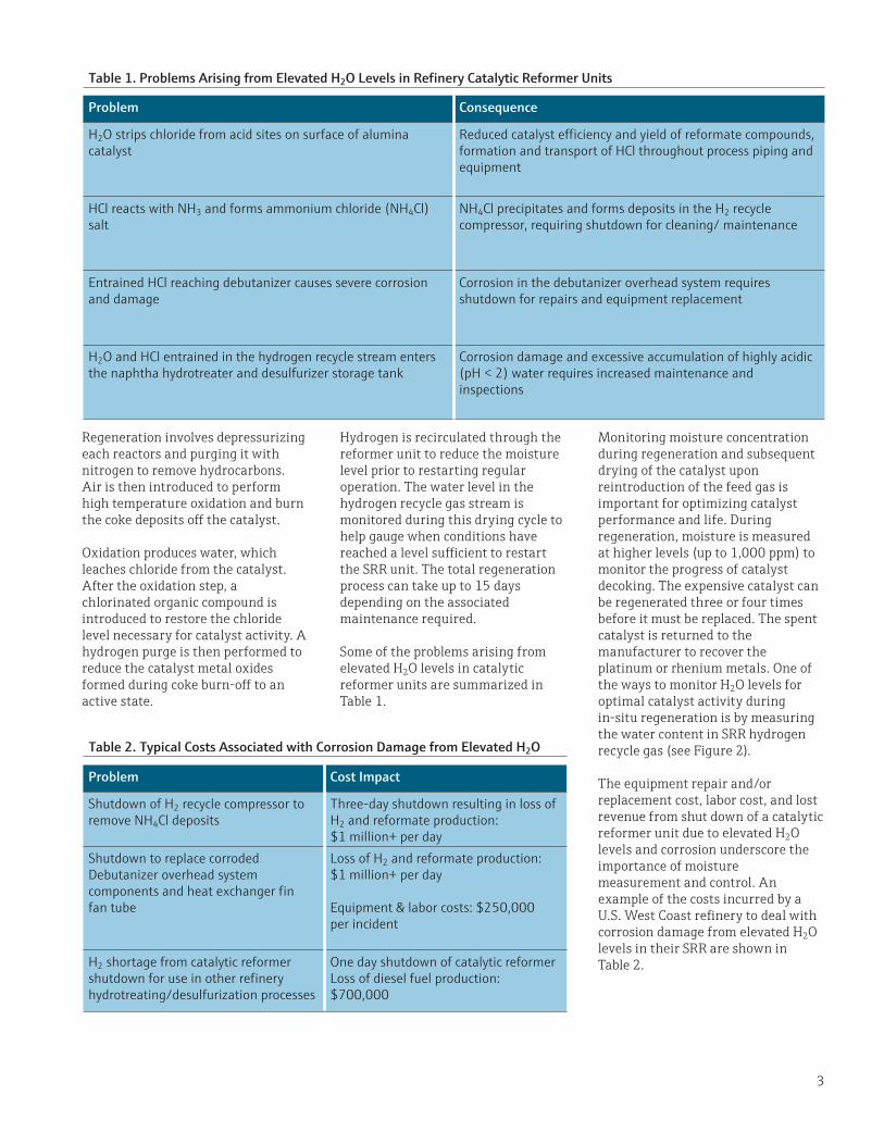
Table 1. Problems Arising from Elevated H2O Levels in Refinery Catalytic Reformer Units
Problem Consequence
H2O strips chloride from acid sites on surface of alumina catalyst
Reduced catalyst efficiency and yield of reformate compounds, formation and transport of HCl throughout process piping and equipment
HCl reacts with NH3 and forms ammonium chloride (NH4Cl) salt
NH4Cl precipitates and forms deposits in the H2 recycle compressor, requiring shutdown for cleaning/ maintenance
Entrained HCl reaching debutanizer causes severe corrosion and damage
Corrosion in the debutanizer overhead system requires shutdown for repairs and equipment replacement
H2O and HCl entrained in the hydrogen recycle stream enters the naphtha hydrotreater and desulfurizer storage tank
Corrosion damage and excessive accumulation of highly acidic (pH < 2) water requires increased maintenance and inspections
Table 2. Typical Costs Associated with Corrosion Damage from Elevated H2O
Problem Cost Impact
Shutdown of H2 recycle compressor to remove NH4Cl deposits
Three-day shutdown resulting in loss of H2 and reformate production: $1 million+ per day
Shutdown to replace corroded Debutanizer overhead system components and heat exchanger fin fan tube
Loss of H2 and reformate production: $1 million+ per day
Equipment & labor costs: $250,000 per incident
H2 shortage from catalytic reformer shutdown for use in other refinery hydrotreating/desulfurization processes
One day shutdown of catalytic reformerLoss of diesel fuel production: $700,000
4
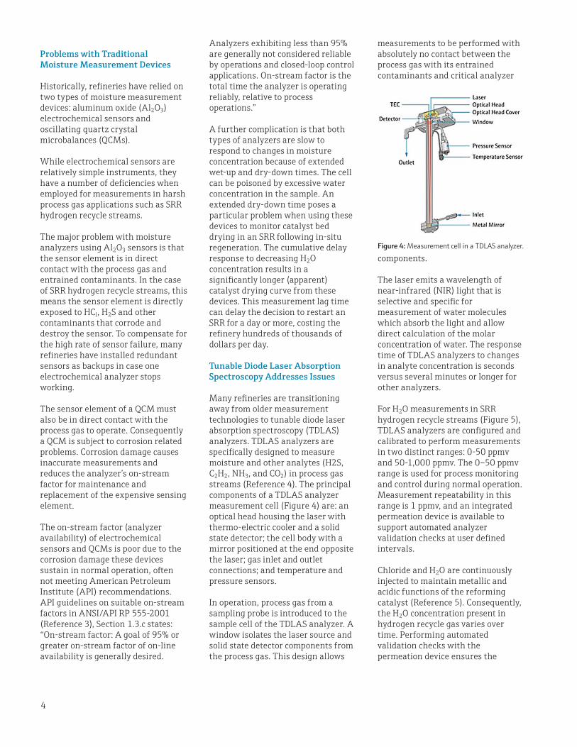
measurements to be performed with absolutely no contact between the process gas with its entrained contaminants and critical analyzer
components.
The laser emits a wavelength of near-infrared (NIR) light that is selective and specific for measurement of water molecules which absorb the light and allow direct calculation of the molar concentration of water. The response time of TDLAS analyzers to changes in analyte concentration is seconds versus several minutes or longer for other analyzers.
For H2O measurements in SRR hydrogen recycle streams (Figure 5), TDLAS analyzers are configured and calibrated to perform measurements in two distinct ranges: 0-50 ppmv and 50-1,000 ppmv. The 0–50 ppmv range is used for process monitoring and control during normal operation. Measurement repeatability in this range is 1 ppmv, and an integrated permeation device is available to support automated analyzer validation checks at user defined intervals.
Chloride and H2O are continuously injected to maintain metallic and acidic functions of the reforming catalyst (Reference 5). Consequently, the H2O concentration present in hydrogen recycle gas varies over time. Performing automated validation checks with the permeation device ensures the
Analyzers exhibiting less than 95% are generally not considered reliable by operations and closed-loop control applications. On-stream factor is the total time the analyzer is operating reliably, relative to process operations.”
A further complication is that both types of analyzers are slow to respond to changes in moisture concentration because of extended wet-up and dry-down times. The cell can be poisoned by excessive water concentration in the sample. An extended dry-down time poses a particular problem when using these devices to monitor catalyst bed drying in an SRR following in-situ regeneration. The cumulative delay response to decreasing H2O concentration results in a significantly longer (apparent) catalyst drying curve from these devices. This measurement lag time can delay the decision to restart an SRR for a day or more, costing the refinery hundreds of thousands of dollars per day.
Tunable Diode Laser Absorption Spectroscopy Addresses Issues
Many refineries are transitioning away from older measurement technologies to tunable diode laser absorption spectroscopy (TDLAS) analyzers. TDLAS analyzers are specifically designed to measure moisture and other analytes (H2S, C2H2, NH3, and CO2) in process gas streams (Reference 4). The principal components of a TDLAS analyzer measurement cell (Figure 4) are: an optical head housing the laser with thermo-electric cooler and a solid state detector; the cell body with a mirror positioned at the end opposite the laser; gas inlet and outlet connections; and temperature and pressure sensors.
In operation, process gas from a sampling probe is introduced to the sample cell of the TDLAS analyzer. A window isolates the laser source and solid state detector components from the process gas. This design allows
Problems with Traditional Moisture Measurement Devices
Historically, refineries have relied on two types of moisture measurement devices: aluminum oxide (Al2O3) electrochemical sensors and oscillating quartz crystal microbalances (QCMs).
While electrochemical sensors are relatively simple instruments, they have a number of deficiencies when employed for measurements in harsh process gas applications such as SRR hydrogen recycle streams.
The major problem with moisture analyzers using Al2O3 sensors is that the sensor element is in direct contact with the process gas and entrained contaminants. In the case of SRR hydrogen recycle streams, this means the sensor element is directly exposed to HCl, H2S and other contaminants that corrode and destroy the sensor. To compensate for the high rate of sensor failure, many refineries have installed redundant sensors as backups in case one electrochemical analyzer stops working.
The sensor element of a QCM must also be in direct contact with the process gas to operate. Consequently a QCM is subject to corrosion related problems. Corrosion damage causes inaccurate measurements and reduces the analyzer’s on-stream factor for maintenance and replacement of the expensive sensing element.
The on-stream factor (analyzer availability) of electrochemical sensors and QCMs is poor due to the corrosion damage these devices sustain in normal operation, often not meeting American Petroleum Institute (API) recommendations. API guidelines on suitable on-stream factors in ANSI/API RP 555-2001 (Reference 3), Section 1.3.c states: “On-stream factor: A goal of 95% or greater on-stream factor of on-line availability is generally desired.
Figure 4: Measurement cell in a TDLAS analyzer.
5
The fast response of TDLAS analyzers to changes in H2O concentration changes can enable a refinery to detect the catalyst dry-down end point and restart an SRR unit a day or more sooner than possible with other moisture measurement devices.
An increasing number of refineries worldwide have recognized the advantages of TDLAS analyzers in this challenging application and adopted the technology to upgrade their SRR process monitoring capability.
The analyzer is programmed to switch into a trending mode when the H2O concentration exceeds 50 ppmv to allow monitoring of higher levels of H2O during in-situ catalyst regeneration and dry down.
TDLAS analyzers are built inside enclosures certified to comply with the hazardous area classifications of refineries around the world.
Summary
Refineries strive to optimize the activity, cycle time between regeneration, and operational life of SRR catalysts. On-line, real-time moisture measurements in the SRR hydrogen recycle gas stream help a refinery assess catalyst condition during normal process operation, in-situ catalyst regeneration and dry down.
The corrosive conditions present in an SRR hydrogen recycle stream reduce the on-stream factor of Al2O3 electrochemical sensors and quartz crystal microbalances. The laser and detector components of a TDLAS analyzer are isolated and protected from direct contact with HCl, providing an on-stream factor exceeding 95% in compliance with ANSI/API RP 555-2001 guidelines.
analyzer is operating properly and H2O measurements are accurate. This allows the control system and plant operators to adjust chloride and H2O levels in the process.
The fast response time of TDLAS analyzers to changes in H2O concentration is advantageous for process monitoring and control during normal operation and for monitoring catalyst dry-down following in-situ regeneration. Organic chloride compounds such as perchloroethylene and water are continuously injected to chlorinate acid sites on the alumina catalyst. As H2O levels increase, chloride is stripped away from the catalyst surface reducing process efficiency. Detecting changes in H2O concentration allows for adjustments of chloride and H2O injection to bring concentrations back into the target operating range.
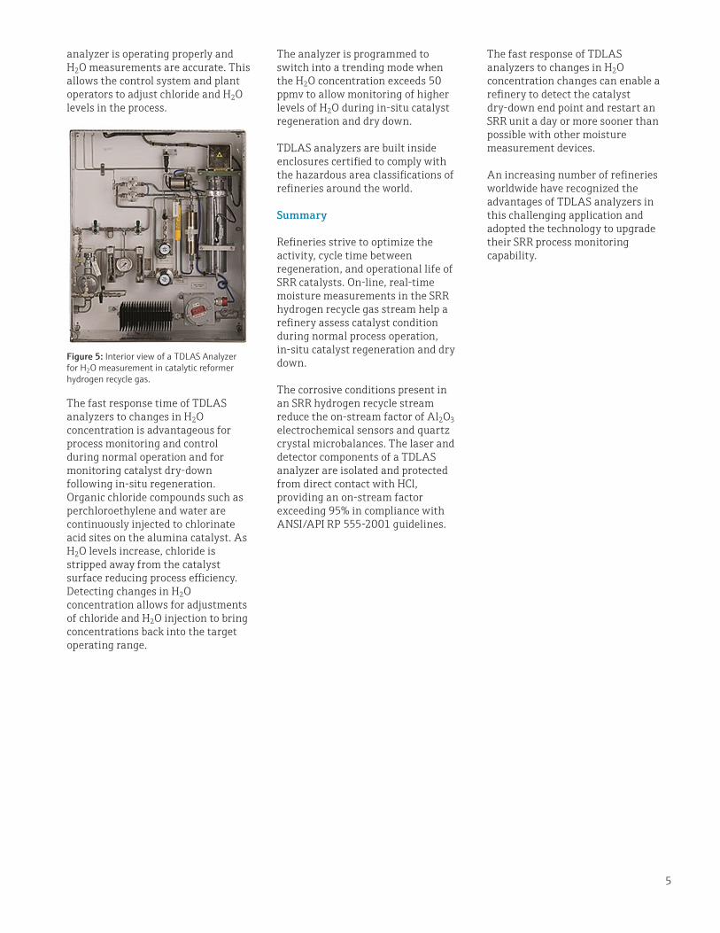
Figure 5: Interior view of a TDLAS Analyzer for H2O measurement in catalytic reformer hydrogen recycle gas.
WP0
1060
C/24
/EN
/01.
17(0
7.17
)©
Endr
ess+
Hau
ser,
Inc.
2017
Endress+Hauser, Inc.2350 Endress PlaceGreenwood, IN 46143Tel: 317-535-7138Sales: 888-ENDRESS (888-363-7377)Fax: [email protected]
About the Author
Gary Engelhart is the Product Line Marketing Manager for SpectraSensors. He is responsible for TDLAS analyzer applications in the hydrocarbon processing industries including natural gas processing, LNG, refining, and petrochemicals. He has 25 years’ experience in analytical instrumentation and chemical process equipment.
References1. Handbook of Petroleum Refining Processes, Chapter 4.1, UOP Platforming Process, Third Edition, McGraw-Hill, 20042. Progress in Catalytic Naphtha Reforming Process: A Review, Rahimpour, M.R., Jafari, M., and Iranshahi, D., Applied Energy 109, 79-93, 2013.3. API Recommended Practice 555, Second Edition, November 20014. U.S. Patents 6,657,198 B1 and 7,679059 B25. Catalytic Reforming Options and Practices, T. Zhou, and F. Baars, www.digitalrefining.com/article/1000479, PTQ Q2 2010-1