Embed Size (px)
Citation preview
Improving Drainage and Drying Features in Certain Conditions: Rain Screen Designs for Absorptive Claddings
December 2008
#9
Improving Drainage and Drying Features in Certain Conditions: Rain Screen Designs for Absorptive Claddings1
December 2008
1. Purpose of this Guide2
Water intrusion and insufficient drainage can pose a potential threat to the durability and usability of residential construction and are an important concern to the building and construction products industries. While approaches to water management may vary among cladding types and climatic regions nationally, the guidelines that follow can be used to help supplement existing manufacturer recommendations and industry standards for management of water in building claddings with the goal of ensuring that levels of moisture in exterior walls do not exceed an acceptable maximum level.
This document presents some guidelines for designing and constructing a building enclosure with a “rain screen” where “absorptive” or “reservoir” type exterior claddings may be used over wood frame wall construction with wood-based sheathing.Specifically, this document describes the use of a “rain screen” design approach to help improve management of moisture in such walls. Open-frame wall construction (without sheathing), or CMU walls with stucco coatings, are not addressed in this document.
An “absorptive” or “reservoir” cladding can be defined as a cladding made of materials that are semi-porous and may transmit or retain some water. Water is absorbed by capillary forces, migrates within the material, and is released by evaporation into the
1 Prepared by the National Association of Home Builders with assistance from Mark F. Williams FAIA Williams Building Diagnostics Inc., Maple Glen, Pennsylvania. Copyright 2008 by the National Association of Home Builders of the United States. All rights reserved. 2 DISCLAIMER
This guide was prepared for the educational and informational use only of the members of the National Association of Home Builders. It is being provided with the understanding that the authors and publisher are not providing legal or other professional advice. The discussions herein are not a substitute for considered professional advice. If specific legal advice or professional assistance is required, the services of a qualified professional should be sought. Reference herein to any specific commercial products, process, or service by trade name, trademark, manufacturer, or otherwise, does not necessarily constitute or imply an endorsement, warranty, guaranty, recommendation, or favored status by the National Association of Home Builders or Williams Building Diagnostics, Inc. The National Association of Home Builders and Williams Building Diagnostics, Inc. expressly disclaim any responsibility for any damages arising from the use, application, or reliance on the recommendations and information contained herein.
1
environment. Some examples of absorptive claddings include portland cement plaster (stucco), manufactured stone veneer,3 and brick and traditional stone masonry veneer.
Exterior cladding instructions and specifications from manufacturers should provide guidance for preventing moisture-related problems from occurring within building enclosures for the range of climates in which the claddings are installed. Constructionprofessionals involved with developing construction practices for “absorptive” or “reservoir” type claddings are increasingly recommending the supplementation of the manufacturer’s existing drainage and drying features by the incorporation of additional positive drainage and drying features, regardless of the cladding manufacturer or particular manufacturer’s guidelines.4 This guide is designed to help builders more effectively use such claddings in a manner that provides a moisture resistant, durable building enclosure. One approach for achieving such an enclosure is through the use of a “rain screen” design approach.
This guide is not meant to replace professional advice and there may be other construction methods or designs that are equally effective at managing moisture. The information contained in this guide is based upon current research results available to the National Association of Home Builders (NAHB). This guide provides a conservative interpretation of current and developing design and construction methods, and is intended to contribute to a better understanding of building science issues that will assist designers and builders to construct absorptive claddings. This guide is not intended to be used as a standard or minimum requirement and the examples cited in this guide are not meant to be considered the only way to achieve a moisture resistant, durable building enclosure.
2. The Need for Better Drainage
“Traditional” absorptive claddings often employ a “concealed barrier” water management approach. In this approach, unwanted water that penetrates behind the cladding is intercepted by a water resistive barrier (WRB), such as felt, building paper and housewraps. Research indicates that traditional WRBs may not necessarily provide sufficient moisture drainage and drying capability to exterior walls in all conditions or, potentially, where not properly installed. Additionally, the WRB itself may deteriorate over time, due to prolonged exposure to moisture, or, rather than properly draining and drying, the unwanted water can migrate through fastener penetrations and cause deterioration of the underlying components.5 The outer surface of the absorptive cladding
3 For purposes of this document manufactured stone veneer means a lightweight, architectural, non-load bearing cementitious material that is adhered to the wall surface to create the appearance of natural stone. 4 Note: Cladding manufacturers should always be consulted before modifying their recommended installation instructions to ensure that warranties are not negatively impacted. 5 Williams, M. F., 2004. “Evaluation of Water Resistive Barrier Performance Using Simple Ponding and Vapor Diffusion Tests,” in: Proceedings, Performance of Exterior Envelopes of Whole Buildings IX, International Conference. (Materials/Barrier/ Practices, Section II-B) Dec. 5-10, 2004, Clearwater, FL. Special Pub. SP-5. Atlanta: American Society of Heating, Refrigerating, and Air-Conditioning Engineers.
2
includes cementitious components such as scratch coats/brown coats, mortar, and, in some applications, precast cement-based facing units. These components are typically adhered with mortar to a scratch coat and metal lath, which is placed over a WRB. The lath is mechanically attached to the underlying structural components. The masonry, mortar and lath are intended to help form a water resistive assembly on the face of the wall, and serve to limit direct moisture exposure to the WRB layer. However, the mortar/scratch coat is capable of absorbing and retaining moisture and is in direct contact with the WRB. Accordingly, the WRB should withstand long-term exposure to moisture, and protect the sheathing from bulk water infiltration. It should also be integrated with window openings and other terminations to prevent the infiltration of water and air.
“Drainage-enhanced” housewraps provide an improved level of drainage, but they can still retain some water, which can migrate through fastener holes to the underlying construction. Drainage and drying performance appears to be improved by using a drainage spacer (furring, drainage mats and the like), to provide a capillary break for ventilation/drying. These overall observations are in agreement with published research (peer reviewed in some instances).6 7 A “rain screen” approach, using drainage spacer materials, offers a supplemental way to provide drainage and drying capabilities for absorptive claddings.8
3. The “Drainage Plane” and the “Rain Screen”
What is meant by the terms “drainage plane” and “rain screen”? The following information is provided to help clarify these terms, beginning with the “drainage plane.” Three factors must be present for water intrusion to occur in a building enclosure: water, an opening, and a force to move the water through the opening. Bulk water (as rain) can accumulate on the exterior surface of a wall, and can migrate through small openings therein when driven by one or more forces: gravity, surface tension, capillarity, air pressure differences, and momentum (kinetic energy). The purpose of a “drainage plane” is to minimize the intrusion of water into the building enclosure.
The drainage plane (called the “moisture barrier” by some) can be defined as a point at which water is diverted and either dried out or drained downward, away from the remainder of the wall assembly. Specifically, it is the vertical (or near-vertical) surface that can accommodate moisture without causing damage to the underlying wall assembly. The location of the drainage plane varies with the type of rainwater control strategy
6 Williams, M. F. 2008. “Evaluating Drainage Characteristics of Water Resistive Barriers as Part of an Overall Durable Wall Approach for the Building Enclosure.” Journal of ASTM International. (On line at www. astm.org) Vol. 5, Issue 7 (July/August 2008) Document I.D. = JAI 101426. 7 Lstiburek, J., 2007. “Water Managed Wall Systems,” in: Bliss, S. (ed.) The JLC Guide to Moisture Control. Williston, VT: The Journal of Light Construction / Hanley Wood LLC. At pages 100, 106. 8 While traditional WRB construction may be perfectly adequate, the use of a “rain screen” design can improve drainage and drying performance in many conditions. It should be noted, however, that even a “rain screen” design should not be considered a “cure-all” for all design conditions, and each builder should consult its own designer.
3
employed in a particular wall design, such as a face-sealed barrier wall, a concealed barrier wall, or a rain screen wall (and its variants), as follows:
a.) Face Sealed Barrier Wall (a.k.a. “Surface Sealed Barrier”). In this approach, all water is intended to be excluded at the outermost face, which serves as the drainage plane. This type of enclosure does not include any provisions to collect and redirect water from behind the cladding to the exterior. When water intrudes behind the cladding, entrapment of such water may occur. Barrier-type EIFS is a common example of face-sealed barrier wall construction.
b.) Concealed Barrier Wall. A “concealed barrier” approach functions to resist rain penetration in two ways: 1) the exterior cladding layer sheds most water at its outer surface, and 2) it anticipates that some water will be driven behind the outer surface and will then be intercepted and managed by the drainage plane, which is sandwiched between the backside of the exterior cladding and the sheathing. Its “drainage” function is performed by the water resistive barrier (WRB), flashings, weep screed accessories, and the like. Bulk water is intended to migrate down the face of the WRB and escape from behind the exterior cladding layer at the weep screeds or flashing or can evaporate. In some instances, water may reach the face of the concealed barrier and, if the cladding is in contact with the concealed barrier, water can become trapped behind the absorptive cladding.
c.) Rain Screen Wall. A “rain screen” approach resists rain penetration in three ways: 1) the exterior cladding layer sheds most water at its outer surface; 2) it anticipates that some water will penetrate behind the outer surface, and intercepts it with a dedicated air space/capillary break; and 3) this space is vented to the outside to not only assist drainage but to encourage drying as well. The air space or capillary break allows more free drainage than the “concealed barrier,” diverting water downward by gravity. To the extent that some water will cross over the air space/capillary break, it is also diverted downward at the drainageplane (water resistive barrier), which is located at the backside of the air space. The air space /capillary break is typically at least 3/8" in width, and can be kept open by spacer materials (furring, drainage mats, profiled boards, and the like) which have been shown to provide superior “drainage efficiency.”9 Finally, venting the air space to the outside not only assists drainage but encourages additional drying as well. This is important, since the “drying rate” can be more significant than “drainage” for long-term performance and durability of exterior building walls. (See the accompanying sample design details in Appendix A.)
9 In November 2006, The International Code Council Evaluation Service issued an “Evaluation Guide (EG-356) for a Moisture Drainage System Used with Exterior Wall Veneers.” This document specifically addressed the evaluation of “vertical and horizontal polystyrene components” as moisture drainage systems behind manufactured stone veneer and stucco, in preparing ICC Evaluation Reports (ER’s) for such materials under the national building codes. Among the required tests was one for “drainage efficiency” (ASTM E-2273), “as modified for this evaluation guideline.” Materials tested under the EG-356 regime were to have a 90 percent drainage efficiency. This Guide is available at: www. icc-es.org.
4
One common type of rain screen wall is the “cavity wall,” exemplified by brick or stone masonry veneer with sheathed wood framing backup, which includes an air space that is a nominal 1” to 2” in width and is vented to the outside. The outer layer of brick or stone is attached to the inner (backup) layer using masonry ties. Here again the drainage plane is located at the backside of the cavity, and its function is performed by the water resistive barrier (WRB), flashings, weeps, and the like.
A “pressure equalized” rain screen (PER) wall uses additional compartmentalization features within the air space to further reduce wind loads and improve performance over an “open” rain screen design. Since the PER approach is not commonly found in residential construction, it is not considered further in this document.
4. Rain Screen Details 10
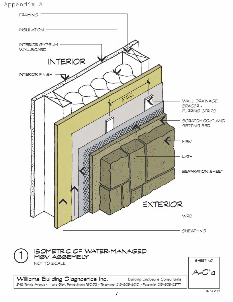
Below are several examples of how drainage and drying can be achieved behind absorptive claddings over wood frame construction, using a variety of readily available materials (See Appendix A for diagrams and Appendix C for information on manufactures of drainage products) in any exterior walls that are fully exposed to the outdoor environment, including gable end walls. In short, the rain screen approach should be considered wherever bulk water can become entrapped behind an exterior wall. This approach may not be needed in walls that are protected by porch roofs, or other significant overhangs, and the like.
Design A-01A shows the cladding installed over galvanized metal lath and a water resistive barrier (separator sheet), with furring strips (e.g., treated wood or plastic to resist moisture related deterioration) as the wall drainage spacer, and a WRB over the sheathing.
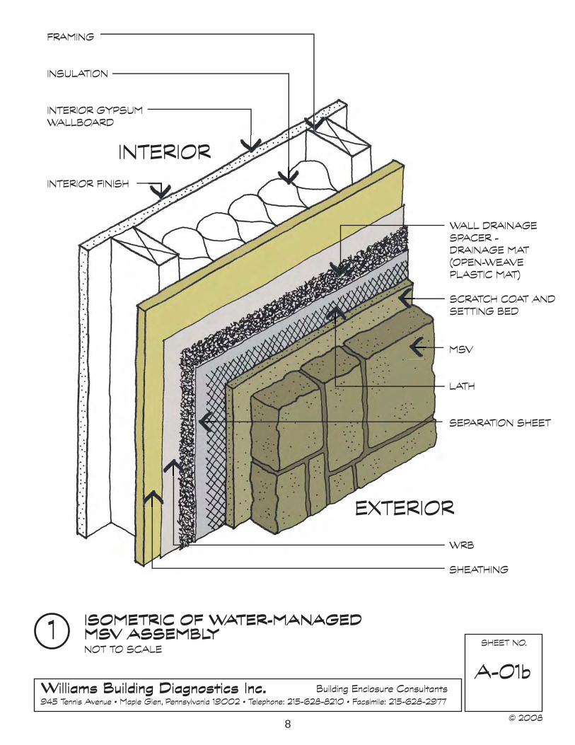
Design A-01B shows the cladding installed over galvanized metal lath and a water resistive barrier (separator sheet), with a drainage mat (open-weave plastic mat) as the wall drainage spacer, and a WRB over the sheathing.
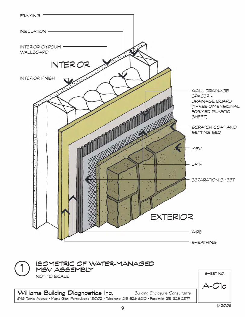
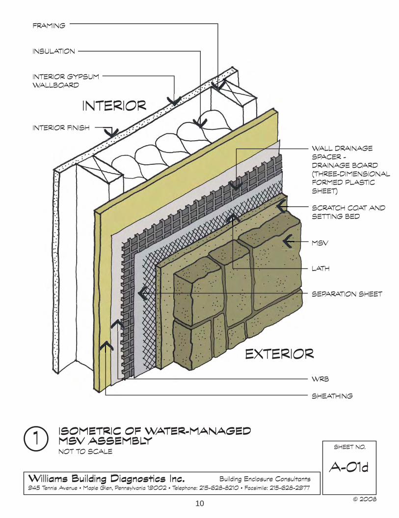
Designs A-01C and A-01D show the cladding installed over galvanized metal lath and a water resistive barrier (separator sheet), with a drainage board (3-dimensional formed plastic sheet) as the wall drainage spacer, and a WRB over the sheathing.
5. Conclusion
In summary, the drainage and drying features of “absorptive” or “reservoir” type claddings can be improved through the incorporation of a “rain screen” design, regardless of the absorptive cladding manufacturer or particular manufacturer’s guidelines. Several regional builders groups and manufacturers now offer recommendations for installing
10 For a detailed discussion of the most critical components of rain screen design and ongoing work in this area see Appendix B.
5
drainage and drying features for these claddings to encourage moisture resistant, durable exterior claddings in construction. These rain screen approaches can be utilized in most areas of the U.S., since it appears that water-related problems in walls can occur in many climate zones and geographic regions.
6
7
Appendix A
8
9
10
Appendix B
Components Discussion
The most critical components of a rain screen design for absorptive claddings are the water resistive barrier (WRB) and the drainage space, which are discussed further below.
Water Resistive Barrier. The 2006 International Residential Code does not address MSV directly, but sets forth minimum performance-based standards for Exterior Coverings. Section R703.1 lists three general criteria for exterior walls. These walls must 1) have a water resistive barrier, 2) be designed and constructed to prevent accumulation of water within the wall assembly, and 3) have a means of draining water that enters the assembly to the exterior. Alternatively, testing is required to demonstrate the viability of other approaches.
Regarding the first criterion, Section R703.2 requires a single layer of No. 15 asphalt felt “or other approved water resistive barrier.”11 This is a general requirement for all types of exterior claddings. As mentioned earlier, research has shown that installing a single WRB layer behind absorptive claddings may not necessarily provide adequate moisture protection in all circumstances, because the WRB itself deteriorates over a few years. In such case, it may also fail to meet the Code’s second criterion (preventing moisture accumulation).
While the Code does not specifically address MSV, it does set forth performance standards for Portland cement based plaster (stucco), an absorptive cladding that is quite similar to MSV. Section R703.6.3 states that a WRB, when applied over wood based sheathing, shall be “vapor permeable, with a performance at least equal to two layers of “Grade D” building paper. This approach calls for two WRB layers and is intended to prevent moisture accumulation of water within the assembly. Therefore, it may be prudent to provide the equivalent to two layers of Grade D paper when using an absorptive cladding (such as stucco or MSV) over wood-based sheathing.
Drainage Space. The Code lists a third criterion (“a means of draining water”). While this is an important provision, the Code does not define what constitutes “drainage.” It should also be noted that the Code does not mention “drying,” although the ability of a wall to “dry out” is just as critical (if not more so) than “draining water” for long-term
11 The 2006 IRC text is as follows: “R703.2 Water-resistive barrier. One layer of No. 15 asphalt felt, free from holes and breaks, complying with ASTM D 226 for Tpe 1 felt or other approved water-resistive barrier shall be applied over studs or sheathing of all exterior walls. Such felt or material shall be applied horizontally, with the upper layer lapped over the lower layer not less than 2 inches (51 mm). Where joints occur, felt shall be lapped not less than 6 inches (152 mm). The felt or other approved material shall be continuous to the top of walls and terminated at penetrations and building appendages in manner to meet the requirements of the exterior wall envelope as described in Section R703.1. Exception: Omission of the water-resistive barrier is permitted in the following situations: 1) In detached accessory buildings. 2) Under exterior wall finish materials as permitted in Table R703.4. 3) Under paperbacked stucco lath when the paper backing is an approved weather-resistive (sic) sheathing paper.”
11
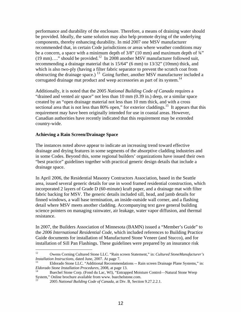
performance and durability of the enclosure. Therefore, a means of draining water should be provided. Ideally, the same solution may also help promote drying of the underlying components, thereby enhancing durability. In mid 2007 one MSV manufacturer recommended that, in certain Code jurisdictions or areas where weather conditions may be a concern, a space with a minimum depth of 3/8” (10 mm) and maximum depth of ¾” (19 mm)….” should be provided.12 In 2008 another MSV manufacturer followed suit, recommending a drainage material that is 15/64” (6 mm) to 13/32” (10mm) thick, and which is also two-ply (having a filter fabric separator to prevent the scratch coat from obstructing the drainage space.) 13 Going further, another MSV manufacturer included a corrugated drainage mat product and weep accessories as part of its system.14
Additionally, it is noted that the 2005 National Building Code of Canada requires a “drained and vented air space” not less than 10 mm (0.39 in.) deep, or a similar space created by an “open drainage material not less than 10 mm thick, and with a cross sectional area that is not less than 80% open,” for exterior claddings.15 It appears that this requirement may have been originally intended for use in coastal areas. However, Canadian authorities have recently indicated that this requirement may be extended country-wide.
Achieving a Rain Screen/Drainage Space
The instances noted above appear to indicate an increasing trend toward effective drainage and drying features in some segments of the absorptive cladding industries and in some Codes. Beyond this, some regional builders’ organizations have issued their own “best practice” guidelines together with practical generic design details that include a drainage space.
In April 2006, the Residential Masonry Contractors Association, based in the Seattle area, issued several generic details for use in wood framed residential construction, which incorporated 2 layers of Grade D (60-minute) kraft paper, and a drainage mat with filter fabric backing for MSV. The generic details included sill, head, and jamb details for finned windows, a wall base termination, an inside-outside wall corner, and a flashing detail where MSV meets another cladding. Accompanying text gave general building science pointers on managing rainwater, air leakage, water vapor diffusion, and thermal resistance.
In 2007, the Builders Association of Minnesota (BAMN) issued a “Member’s Guide” to the 2006 International Residential Code, which included references to Building Practice Guide documents for installation of Manufactured Stone Veneer (and Stucco), and for installation of Sill Pan Flashings. These guidelines were prepared by an insurance risk
12 Owens Corning Cultured Stone LLC. “Rain screen Statement,” in: Cultured StoneManufacturer’s Installation Instructions, dated June, 2007. At page 7. 13 Eldorado Stone LLC. “Additional Recommendations -- Rain screen Drainage Plane Systems,” in: Eldorado Stone Installation Procedures, 2008, at page 13. 14 Buechel Stone Corp. (Fond du Lac, WI), “Entrapped Moisture Control—Natural Stone Weep System,” Online brochure available from www. buechelstone.com. 15 2005 National Building Code of Canada, at Div. B, Section 9.27.2.2.1.
12
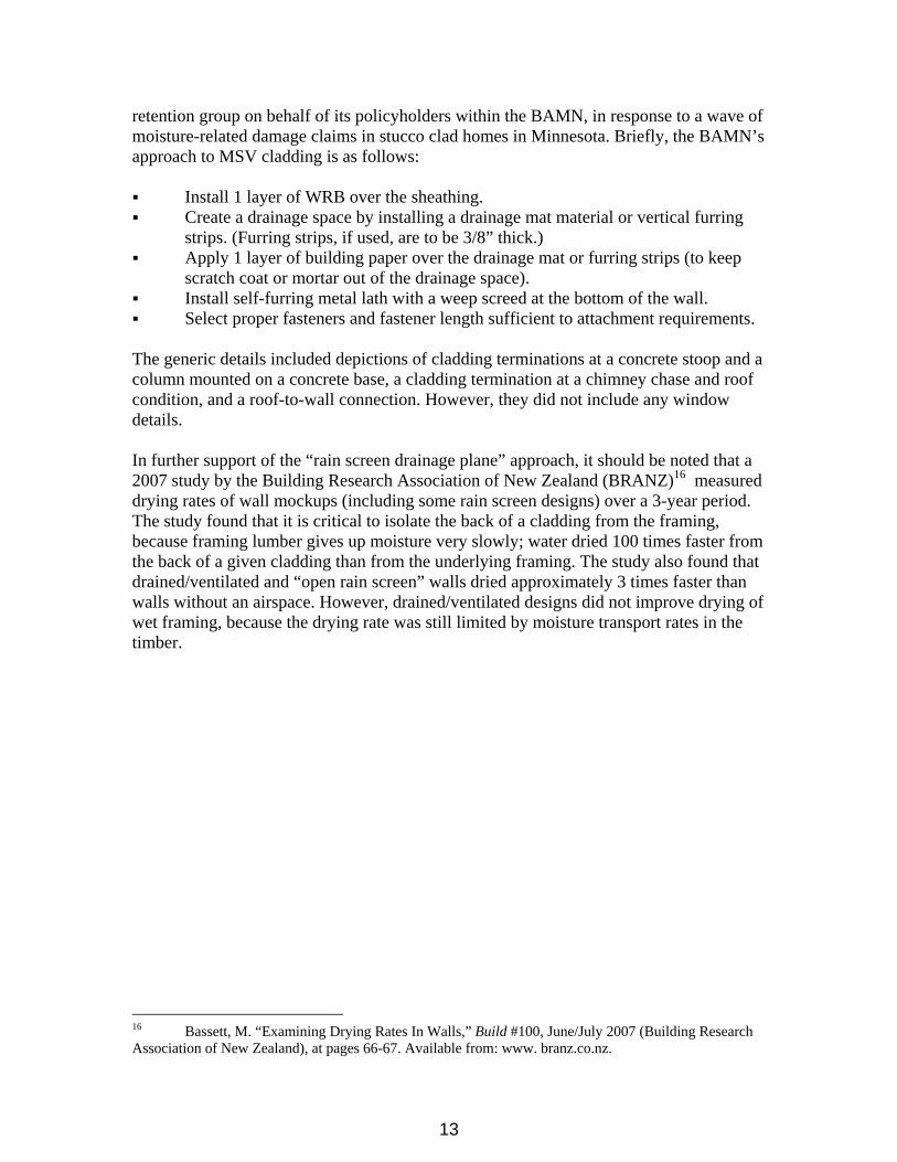
retention group on behalf of its policyholders within the BAMN, in response to a wave of moisture-related damage claims in stucco clad homes in Minnesota. Briefly, the BAMN’s approach to MSV cladding is as follows:
Install 1 layer of WRB over the sheathing. Create a drainage space by installing a drainage mat material or vertical furring strips. (Furring strips, if used, are to be 3/8” thick.) Apply 1 layer of building paper over the drainage mat or furring strips (to keep scratch coat or mortar out of the drainage space). Install self-furring metal lath with a weep screed at the bottom of the wall. Select proper fasteners and fastener length sufficient to attachment requirements.
The generic details included depictions of cladding terminations at a concrete stoop and a column mounted on a concrete base, a cladding termination at a chimney chase and roof condition, and a roof-to-wall connection. However, they did not include any window details.
In further support of the “rain screen drainage plane” approach, it should be noted that a 2007 study by the Building Research Association of New Zealand (BRANZ)16 measured drying rates of wall mockups (including some rain screen designs) over a 3-year period. The study found that it is critical to isolate the back of a cladding from the framing, because framing lumber gives up moisture very slowly; water dried 100 times faster from the back of a given cladding than from the underlying framing. The study also found that drained/ventilated and “open rain screen” walls dried approximately 3 times faster than walls without an airspace. However, drained/ventilated designs did not improve drying of wet framing, because the drying rate was still limited by moisture transport rates in the timber.
16 Bassett, M. “Examining Drying Rates In Walls,” Build #100, June/July 2007 (Building Research Association of New Zealand), at pages 66-67. Available from: www. branz.co.nz.
13
Appendix C
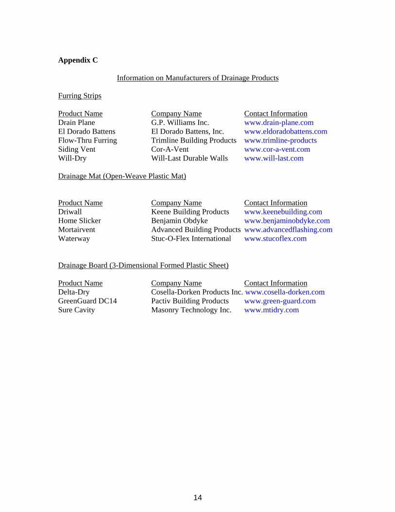
Information on Manufacturers of Drainage Products
Furring Strips
Product Name Company Name Contact InformationDrain Plane G.P. Williams Inc. www.drain-plane.com El Dorado Battens El Dorado Battens, Inc. www.eldoradobattens.comFlow-Thru Furring Trimline Building Products www.trimline-products Siding Vent Cor-A-Vent www.cor-a-vent.comWill-Dry Will-Last Durable Walls www.will-last.com
Drainage Mat (Open-Weave Plastic Mat)
Product Name Company Name Contact InformationDriwall Keene Building Products www.keenebuilding.com Home Slicker Benjamin Obdyke www.benjaminobdyke.com Mortairvent Advanced Building Products www.advancedflashing.com Waterway Stuc-O-Flex International www.stucoflex.com
Drainage Board (3-Dimensional Formed Plastic Sheet)
Product Name Company Name Contact InformationDelta-Dry Cosella-Dorken Products Inc. www.cosella-dorken.comGreenGuard DC14 Pactiv Building Products www.green-guard.comSure Cavity Masonry Technology Inc. www.mtidry.com
14