Embed Size (px)
Citation preview
MAI ET AL.: DETECTION OF DEFORMABLE OBJECTS IN VOL. DATA 1
Improving Detection of Deformable Objects inVolumetric Data
Dominic Mai 1,3
Jasmin Durr 2
Klaus Palme 2,3
Olaf Ronneberger 1,3
1Computer Science DepartmentUniversity of FreiburgGermany
2 Institute of Biology II - BotanyUniversity of FreiburgGermany
3BIOSS Centre for Biological SignallingStudiesUniversity of FreiburgGermany
Abstract
In this paper, we investigate class level object detection of deformable ob-jects. To this end, we aim for cell detection in volumetric images of dense planttissue (Arabidopsis Thaliana), obtained from a confocal laser scanning micro-scope. In 3D volumetric data, the detection model does not have to deal withscale, occlusion and viewpoint dependent changes of the appearance, however,our application needs high recall and precision. We implement Felsenszwalb’sDeformable Part Model for volumetric data. Corresponding locations for parttraining are obtained via elastic registration. We identify limitations of its starshaped deformation model and show that a pairwise connected detection modelcan outperform the star shaped Deformable Part Model in this setting.
1 Introduction
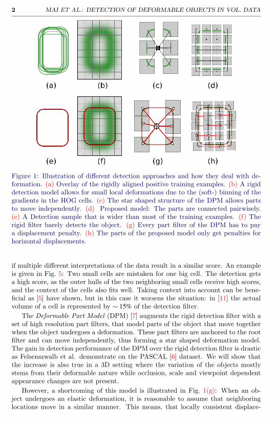
The analysis of biological or medical images is often done by fitting a model to thedata. This model fitting is the basis for a further analysis, e.g. to interpret geneexpression patterns in the correct anatomical context. If the location of the soughtstructures is unknown, the model fitting usually consists of a coarse localization step(detection) followed by a finer grained fitting to the data (alignment), e.g. [3]. Acrucial part in this processing is the discriminative power of the detection model: Ifthe wrong object is detected, the best alignment cannot correct for this error. Mai etal. [11] use a rigid detector based on histograms of oriented gradients (HOG) and anelastic registration to detect and align a certain type of cells in Arabidopsis Thaliana,in order to get a segmentation and reconstruction of the root. This approach, how-ever, fails to produce good results for other layers with less distinctive cell shapes.The reason is the rigid detection model. While it can account for some local defor-mation of the cells, as illustrated in Fig. 1(b), false positive detections are frequent
c© 2014. The copyright of this document resides with its authors.It may be distributed unchanged freely in print or electronic forms.
2 MAI ET AL.: DETECTION OF DEFORMABLE OBJECTS IN VOL. DATA
Figure 1: Illustration of different detection approaches and how they deal with de-formation. (a) Overlay of the rigidly aligned positive training examples. (b) A rigiddetection model allows for small local deformations due to the (soft-) binning of thegradients in the HOG cells. (c) The star shaped structure of the DPM allows partsto move independently. (d) Proposed model: The parts are connected pairwisely.(e) A Detection sample that is wider than most of the training examples. (f) Therigid filter barely detects the object. (g) Every part filter of the DPM has to paya displacement penalty. (h) The parts of the proposed model only get penalties forhorizontal displacements.
if multiple different interpretations of the data result in a similar score. An exampleis given in Fig. 5: Two small cells are mistaken for one big cell. The detection getsa high score, as the outer hulls of the two neighboring small cells receive high scores,and the context of the cells also fits well. Taking context into account can be bene-ficial as [5] have shown, but in this case it worsens the situation: in [11] the actualvolume of a cell is represented by ∼ 15% of the detection filter.
The Deformable Part Model (DPM) [7] augments the rigid detection filter with aset of high resolution part filters, that model parts of the object that move togetherwhen the object undergoes a deformation. These part filters are anchored to the rootfilter and can move independently, thus forming a star shaped deformation model.The gain in detection performance of the DPM over the rigid detection filter is drasticas Felsenszwalb et al. demonstrate on the PASCAL [6] dataset. We will show thatthe increase is also true in a 3D setting where the variation of the objects mostlystems from their deformable nature while occlusion, scale and viewpoint dependentappearance changes are not present.
However, a shortcoming of this model is illustrated in Fig. 1(g): When an ob-ject undergoes an elastic deformation, it is reasonable to assume that neighboringlocations move in a similar manner. This means, that locally consistent displace-
MAI ET AL.: DETECTION OF DEFORMABLE OBJECTS IN VOL. DATA 3
ments should not be penalized, while locally inconsistent displacements should. Thepatches of the DPM can not account for this due to the star shaped structure of thedeformation model.
The poselet detection framework [2] offers pairwise connectivity between poseletactivations, however, their approach is more focused on modeling appearance changesbased on viewpoint and articulation. The poselets are too big for modeling localdeformations and the pairwise connections via keypoint predictions are used for agreedy clustering and rescoring.
The research on deformable image registration has produced powerful deformationmodels for the elastic alignment of data, e.g. [1, 12]. For an overview and a systematicclassification of state of the art methods, see [14]. Many classes of deformations canbe modeled, however, those models are not designed to have the discriminative powerof above mentioned detection approaches. A comparison of alignments from differentobjects based on their registration score is therefore not very meaningful, as we showin the experiments section.
Contribution. We combine the ideas of discriminative detection and elastic reg-istration by using a discriminative similarity measure with a pairwise deformationmodel, see Fig. 1(d,h). To this end, we show that deformable detection approachescan be formulated in a general elastic registration framework. We implement theproposed pairwise model and the DPM with a non-latent part training for 3D vol-umetric data. We show that we can improve precision and recall by rescoring withthe alignment scores of the proposed model. We plan to make our software publiclyavailable1.
2 Modeling Deformations
In this section we introduce the formal framework used for deformable registration.We then show that detection of deformable objects is an instance of deformableregistration by formulating two popular approaches in this framework and therebymotivate our approach.
2.1 Deformable Registration
The goal in non-linear deformable registration is to estimate a transformationθ : R3 → R3 that transforms the volumetric moving image M onto the fixed im-age F such that it is most similar to the fixed image with respect to a given similaritymeasure. We define a volumetric image I as a function:
I :R3→R. (1)
We can denote the transformation of the moving image M with the function compo-sition operator ◦:
M = M ◦θ (2)
1http://lmb.informatik.uni-freiburg.de/people/maid/
4 MAI ET AL.: DETECTION OF DEFORMABLE OBJECTS IN VOL. DATA
Formally, we can now state the goal of the deformable registration as the optimizationof the following energy functional:
E(F,M,θ) = S(F,M ◦θ)+ λR(θ) (3)
S measures the degree of alignment between the fixed image F and the transformedmoving image M ◦ θ . R regularizes the transformation θ . λ controls the strengthof this regularization. S is a mapping from the joint image space to the real values(R3→R,R3→R)→R.
2.2 Discriminative Detection
The goal in object class detection is to locate an object of a certain class in an image.We will first have a look at rigid detection, as illustrated in Fig. 1(b). This approachcan be formalized in the elastic registration framework (Eqn. 3):
Erigid(C,M,r) = C(
f(M ◦θ r
)), (4)
where f crops the image and transforms it into a vectorial feature-space. C is theclassifier that obtains the similarity score of the observed image region and the objectmodel. The transformation θ r is parameterized by r. In rigid 2D detection for naturalimages it usually has three degrees of freedom: two translational (r1,r2) and one forscale (r3). Transformations that result in local optima of E give the object locations.This approach was popularized by Dalal and Triggs [5] who introduced HOG featuresand use a linear support vector machine (SVM) as classifier:
C(
ξ r
)= 〈w,ξ r〉, (5)
with w being the separating hyperplane. For simplicity of notation we defineξ r := f
(M ◦θ r
). They optimize it by performing an exhaustive search over all lo-
cations and scales using a sliding window approach in a Gaussian scale-space. Thereis no penalty on the applied transformation (λ = 0), as all transformations are as-sumed to be equally likely. However, the ability of the model to cope with small localdeformations is encoded in the HOG feature representation (Fig. 1(f)): No penaltyis paid for a gradient that moves within a feature cell. Due to the soft binning, agradient that enters a neighboring cell receives a lower score.
Felsenszwalb et al. [7] augmented the rigid detection model with a star shapeddeformation model that is regularized by a quadratic penalizer. The concept of theirDeformable Part Model is illustrated in Fig. 1(c): The Model consists of a root filterand several part filters, whose locations are “anchored” to the root filter. The rootfilter is a rigid detection filter as introduced by Dalal and Triggs and responsible forthe coarse localization of the object. The part filters are much smaller than the rootfilter, but at twice the resolution. They are responsible for the precise localization ofregions of the object that are assumed to move together when the object undergoesa deformation.
All filters wi are realized as linear SVMs, with w0 being the root filter. Duringtraining, the relative mean locations of the parts w1 . . .wn are learned along with the
MAI ET AL.: DETECTION OF DEFORMABLE OBJECTS IN VOL. DATA 5
costs for a displacement of the part from its most likely location:
EDPM(w0, . . . ,wn,M,r, t1, . . . , tn) = 〈w0,ξ r〉+n∑
i=1
〈wi,ξiti〉−λ
n∑i=1
R(ti)
(6)
The root filter location and scale r are searched exhaustively as in the rigid setting.For each location the optimal relative part-placements ti, i ∈ {1, . . . ,n} are indepen-dent translations that can be found efficiently by using generalized distance trans-forms [8]. Note that the root filter location and the part placements also could havebeen expressed by a parameterized dense transformation θ(r, t1, . . . , tn) in the senseof Eqn. 3.
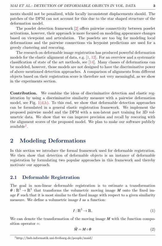
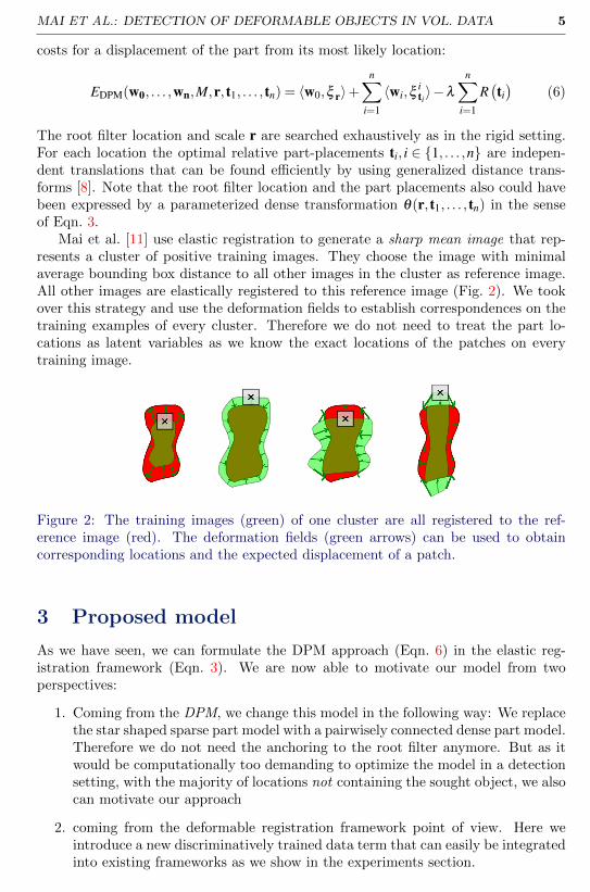
Mai et al. [11] use elastic registration to generate a sharp mean image that rep-resents a cluster of positive training images. They choose the image with minimalaverage bounding box distance to all other images in the cluster as reference image.All other images are elastically registered to this reference image (Fig. 2). We tookover this strategy and use the deformation fields to establish correspondences on thetraining examples of every cluster. Therefore we do not need to treat the part lo-cations as latent variables as we know the exact locations of the patches on everytraining image.
Figure 2: The training images (green) of one cluster are all registered to the ref-erence image (red). The deformation fields (green arrows) can be used to obtaincorresponding locations and the expected displacement of a patch.
3 Proposed model
As we have seen, we can formulate the DPM approach (Eqn. 6) in the elastic reg-istration framework (Eqn. 3). We are now able to motivate our model from twoperspectives:
1. Coming from the DPM, we change this model in the following way: We replacethe star shaped sparse part model with a pairwisely connected dense part model.Therefore we do not need the anchoring to the root filter anymore. But as itwould be computationally too demanding to optimize the model in a detectionsetting, with the majority of locations not containing the sought object, we alsocan motivate our approach
2. coming from the deformable registration framework point of view. Here weintroduce a new discriminatively trained data term that can easily be integratedinto existing frameworks as we show in the experiments section.
6 MAI ET AL.: DETECTION OF DEFORMABLE OBJECTS IN VOL. DATA
We propose a Discriminative Deformable Model (DDM):
Eprop(w1, . . . ,wNp ,M,U) =
Np∑i=1
〈wi,ξ θ(pi)〉︸ ︷︷ ︸
discriminative data term
−λ
∑(i, j)∈E
∥∥∥U(pi)−U(p j)∥∥∥
2∥∥∥pi−p j
∥∥∥2︸ ︷︷ ︸
pairwise deformation model
(7)
For the explanation of the symbols, have a look at Fig. 1(d): We discretely sam-ple Np control points pi at equidistant image locations. Each control point is thecenter of a linear support vector machine wi that encodes the appearance for therespective patch. We will train all the wi jointly. U : R3 → R3 is a displacementfield. The relationship between a transformation and a displacement field is the fol-lowing: θ(p) = U(p) + p. The feature representation of an image patch extracted atthe location p + U(p) is represented by ξ θ(p). The regularizer penalizes inconsistentmovements of neighboring patches: The deviation vector d = U(p1)−U(p2) is 0 whentwo connected control points move with the same displacement. It is normalized by
the initial edge length∥∥∥pi−p j
∥∥∥2. E is the connectivity set, i.e. all the edges (i, j)
between the parts. λ controls the degree of regularization.
3.1 Training
In this section we describe how we train the patch detectors wi and estimate λ whichcontrols the degree of regularization. As the patch detectors are linear support vectormachines, we need to present them with normalized positive and negative trainingexamples. For the normalization, the effect of the transformation θ needs to becanceled out. For instance, to train a rigid detector, the positive examples need tobe position and scale normalized (Fig. 1(a)). As we want to normalize for non lineardeformations, we use the detection and alignment framework from [11] to mine shapenormalized positive and negative training examples.
We describe the processing pipeline for a single detection hypothesis yielded froma single detector. We put the sharp mean image Z on the rotation normalized imageB at the detection location. We compute the alignment Z = Z ◦ θ using the elasticregistration from [12]. Then we compare the corresponding warped segmentationmask SZ with the ground truth segmentation to classify the detection whether it willbe the basis for a positive (+) or a negative (−) training example. Now we shapenormalize the image B at the detection location by aligning it to the sharp meanimage with the inverse transformation: B = B◦θ
−1. We create a set of Np equidistantcontrol points pi, such that the induced patches at the control point locations pi forma partition of the sharp mean image Z. We compute 3D HOG features from the shapenormalized image B and extract the patches ξ pi
for every control point.
We process all detections obtained from the training dataset in the described
manner and end up with a positive training set S+i =
{ξ 1
pi, . . . ,ξ
N+pi
}and a negative
training set S−i ={
ξ 1pi, . . . ,ξ
N−pi
}for each control point pi.
Finally, we jointly train the patch detectors wi using libsvm [4]. To this end weconcatenate the features from all patches. A training vector Ti has the following
MAI ET AL.: DETECTION OF DEFORMABLE OBJECTS IN VOL. DATA 7
structure:
Ti =
[(ξ
ip1
)ᵀ, . . . ,(ξip|P |)
ᵀ], i ∈ [1,N], N = N+ + N− (8)
After training, the joint separating hyperplane has the structure W =
[wᵀ
1 , . . . ,wᵀ|P|
]ᵀ— the single patch detectors wi can thus easily be obtained.
As the codomain of the wp is not normalized, it is crucial to find a good valuefor the strength of the regularization λ . We achieve this by doing an exponentialgrid search with the goal of maximizing the intersection over union of the alignedsegmentation masks with the ground truth segmentations.
3.2 Optimization
The structure of our model Eqn. 7 is identical to the model used in the vibez regis-tration [12]. The only difference is that we replace the normalized cross correlationbased data term with the discriminative patch detectors wi. We formulate it asa discrete labeling problem (Markov Random Field) with unary and binary costs.The sought label is the displacement U(pi) at a control point. This means that wehave to evaluate a discrete set of displacement hypotheses d j ∈ R3 at every con-trol point to obtain the unary costs −〈wi,ξ p+d j
〉. As in the vibez registration, we
search along the axes and diagonals within a certain radius r, therefore we haved j ∈ {r · (e1,e2,e3)ᵀ | r ∈N,ei ∈ {−1,0,1}}. The initial dense displacement field Uis set to zero.
The binary costs are given by the regularizer of the model, as they couple neigh-boring control points: λ
∑(p1,p2)∈E
1‖p1−p2‖ 2
∥∥U(p1)−U(p2)∥∥
2.
We solve it with iterated graph cuts using the very efficient fastPD algorithm [9].The values of U between the control points are obtained through a cubic splineinterpolation. As the performance breaks down for very big search radii r, we needa coarse initialization. Therefore we run the optimization on top of the detectionhypotheses of a rigid detector or a DPM detector.
4 Experiments
For the quantitative evaluation we had two roots (r06, r14 ) with ground truth seg-mentation available. We use one root for training and one for testing and vice versa.Each root contains about ∼ 2500 cells, so the generation of ground truth is cumber-some work. It is obtained by manually verifying a watershed segmentation computedon enhanced data [10]. For the available roots, this bottom up segmentation methodgives good results, but it fails for data of worse quality [11], where the generationof reliable ground truth segmentations is nearly impossible. However, the goal ofthis section is to give a quantitative comparison between the different detection andalignment strategies discussed in this paper.
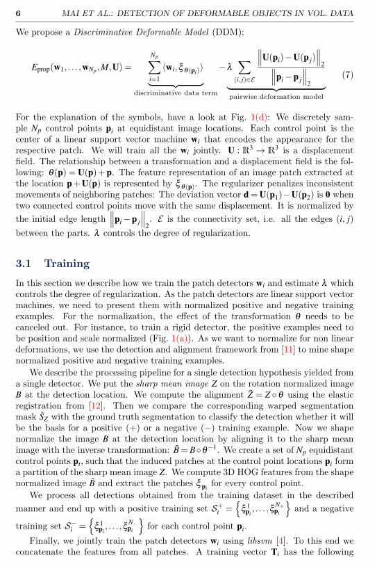
We chose a cell layer (Fig. 3), where the rigid detection followed by alignmentapproach from [11] fails to produce good results (Fig. 4). We follow their trainingprocedure and split the training data into 15 clusters. For each cluster, we train arigid detector and a DPM detector, as well as a sharp mean image for the gradient
8 MAI ET AL.: DETECTION OF DEFORMABLE OBJECTS IN VOL. DATA
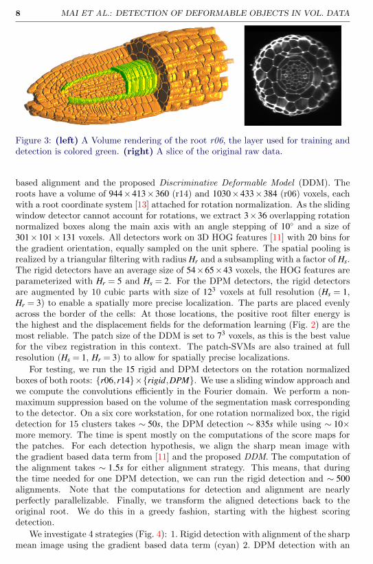
Figure 3: (left) A Volume rendering of the root r06, the layer used for training anddetection is colored green. (right) A slice of the original raw data.
based alignment and the proposed Discriminative Deformable Model (DDM). Theroots have a volume of 944×413×360 (r14) and 1030×433×384 (r06) voxels, eachwith a root coordinate system [13] attached for rotation normalization. As the slidingwindow detector cannot account for rotations, we extract 3×36 overlapping rotationnormalized boxes along the main axis with an angle stepping of 10◦ and a size of301×101×131 voxels. All detectors work on 3D HOG features [11] with 20 bins forthe gradient orientation, equally sampled on the unit sphere. The spatial pooling isrealized by a triangular filtering with radius Hr and a subsampling with a factor of Hs.The rigid detectors have an average size of 54×65×43 voxels, the HOG features areparameterized with Hr = 5 and Hs = 2. For the DPM detectors, the rigid detectorsare augmented by 10 cubic parts with size of 123 voxels at full resolution (Hs = 1,Hr = 3) to enable a spatially more precise localization. The parts are placed evenlyacross the border of the cells: At those locations, the positive root filter energy isthe highest and the displacement fields for the deformation learning (Fig. 2) are themost reliable. The patch size of the DDM is set to 73 voxels, as this is the best valuefor the vibez registration in this context. The patch-SVMs are also trained at fullresolution (Hs = 1, Hr = 3) to allow for spatially precise localizations.
For testing, we run the 15 rigid and DPM detectors on the rotation normalizedboxes of both roots: {r06,r14}×{rigid,DPM}. We use a sliding window approach andwe compute the convolutions efficiently in the Fourier domain. We perform a non-maximum suppression based on the volume of the segmentation mask correspondingto the detector. On a six core workstation, for one rotation normalized box, the rigiddetection for 15 clusters takes ∼ 50s, the DPM detection ∼ 835s while using ∼ 10×more memory. The time is spent mostly on the computations of the score maps forthe patches. For each detection hypothesis, we align the sharp mean image withthe gradient based data term from [11] and the proposed DDM. The computation ofthe alignment takes ∼ 1.5s for either alignment strategy. This means, that duringthe time needed for one DPM detection, we can run the rigid detection and ∼ 500alignments. Note that the computations for detection and alignment are nearlyperfectly parallelizable. Finally, we transform the aligned detections back to theoriginal root. We do this in a greedy fashion, starting with the highest scoringdetection.
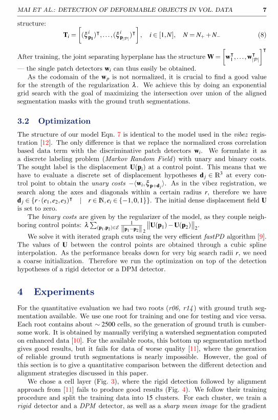
We investigate 4 strategies (Fig. 4): 1. Rigid detection with alignment of the sharpmean image using the gradient based data term (cyan) 2. DPM detection with an
MAI ET AL.: DETECTION OF DEFORMABLE OBJECTS IN VOL. DATA 9
(a) (b)
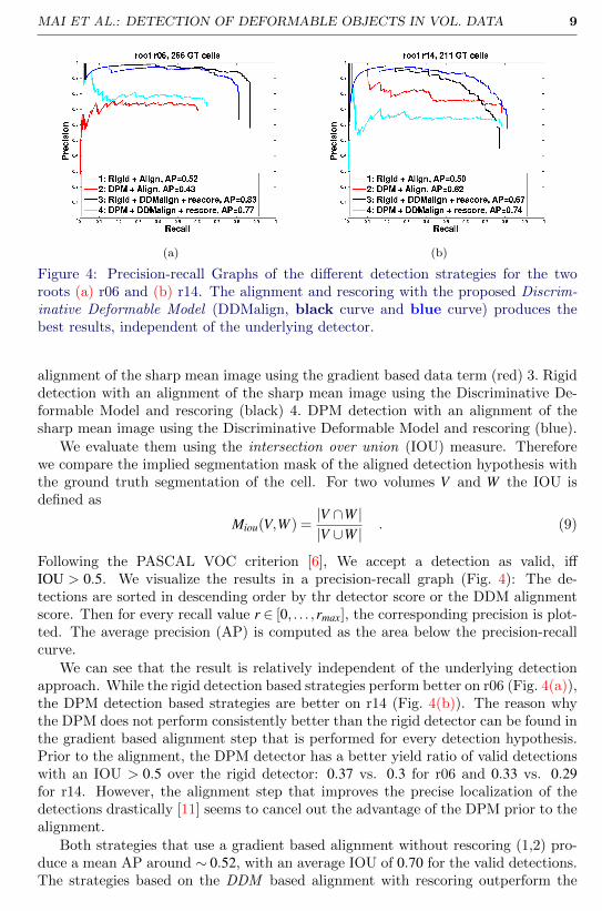
Figure 4: Precision-recall Graphs of the different detection strategies for the tworoots (a) r06 and (b) r14. The alignment and rescoring with the proposed Discrim-inative Deformable Model (DDMalign, black curve and blue curve) produces thebest results, independent of the underlying detector.
alignment of the sharp mean image using the gradient based data term (red) 3. Rigiddetection with an alignment of the sharp mean image using the Discriminative De-formable Model and rescoring (black) 4. DPM detection with an alignment of thesharp mean image using the Discriminative Deformable Model and rescoring (blue).
We evaluate them using the intersection over union (IOU) measure. Thereforewe compare the implied segmentation mask of the aligned detection hypothesis withthe ground truth segmentation of the cell. For two volumes V and W the IOU isdefined as
Miou(V,W ) =|V ∩W ||V ∪W |
. (9)
Following the PASCAL VOC criterion [6], We accept a detection as valid, iffIOU > 0.5. We visualize the results in a precision-recall graph (Fig. 4): The de-tections are sorted in descending order by thr detector score or the DDM alignmentscore. Then for every recall value r ∈ [0, . . . ,rmax], the corresponding precision is plot-ted. The average precision (AP) is computed as the area below the precision-recallcurve.
We can see that the result is relatively independent of the underlying detectionapproach. While the rigid detection based strategies perform better on r06 (Fig. 4(a)),the DPM detection based strategies are better on r14 (Fig. 4(b)). The reason whythe DPM does not perform consistently better than the rigid detector can be found inthe gradient based alignment step that is performed for every detection hypothesis.Prior to the alignment, the DPM detector has a better yield ratio of valid detectionswith an IOU > 0.5 over the rigid detector: 0.37 vs. 0.3 for r06 and 0.33 vs. 0.29for r14. However, the alignment step that improves the precise localization of thedetections drastically [11] seems to cancel out the advantage of the DPM prior to thealignment.
Both strategies that use a gradient based alignment without rescoring (1,2) pro-duce a mean AP around ∼ 0.52, with an average IOU of 0.70 for the valid detections.The strategies based on the DDM based alignment with rescoring outperform the
10 MAI ET AL.: DETECTION OF DEFORMABLE OBJECTS IN VOL. DATA
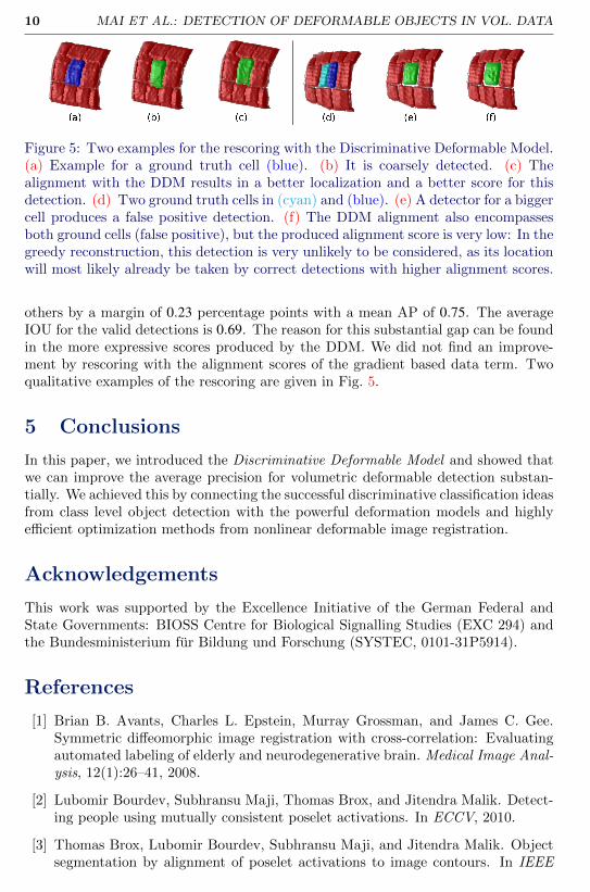
Figure 5: Two examples for the rescoring with the Discriminative Deformable Model.(a) Example for a ground truth cell (blue). (b) It is coarsely detected. (c) Thealignment with the DDM results in a better localization and a better score for thisdetection. (d) Two ground truth cells in (cyan) and (blue). (e) A detector for a biggercell produces a false positive detection. (f) The DDM alignment also encompassesboth ground cells (false positive), but the produced alignment score is very low: In thegreedy reconstruction, this detection is very unlikely to be considered, as its locationwill most likely already be taken by correct detections with higher alignment scores.
others by a margin of 0.23 percentage points with a mean AP of 0.75. The averageIOU for the valid detections is 0.69. The reason for this substantial gap can be foundin the more expressive scores produced by the DDM. We did not find an improve-ment by rescoring with the alignment scores of the gradient based data term. Twoqualitative examples of the rescoring are given in Fig. 5.
5 Conclusions
In this paper, we introduced the Discriminative Deformable Model and showed thatwe can improve the average precision for volumetric deformable detection substan-tially. We achieved this by connecting the successful discriminative classification ideasfrom class level object detection with the powerful deformation models and highlyefficient optimization methods from nonlinear deformable image registration.
Acknowledgements
This work was supported by the Excellence Initiative of the German Federal andState Governments: BIOSS Centre for Biological Signalling Studies (EXC 294) andthe Bundesministerium fur Bildung und Forschung (SYSTEC, 0101-31P5914).
References
[1] Brian B. Avants, Charles L. Epstein, Murray Grossman, and James C. Gee.Symmetric diffeomorphic image registration with cross-correlation: Evaluatingautomated labeling of elderly and neurodegenerative brain. Medical Image Anal-ysis, 12(1):26–41, 2008.
[2] Lubomir Bourdev, Subhransu Maji, Thomas Brox, and Jitendra Malik. Detect-ing people using mutually consistent poselet activations. In ECCV, 2010.
[3] Thomas Brox, Lubomir Bourdev, Subhransu Maji, and Jitendra Malik. Objectsegmentation by alignment of poselet activations to image contours. In IEEE
MAI ET AL.: DETECTION OF DEFORMABLE OBJECTS IN VOL. DATA 11
International Conference on Computer Vision and Pattern Recognition (CVPR),2011.
[4] Chih-Chung Chang and Chih-Jen Lin. LIBSVM: A library for support vectormachines. ACM Transactions on Intelligent Systems and Technology, 2:27:1–27:27, 2011.
[5] Navneet Dalal and Bill Triggs. Histograms of oriented gradients for humandetection. In Cordelia Schmid, Stefano Soatto, and Carlo Tomasi, editors, In-ternational Conference on Computer Vision & Pattern Recognition, 2005.
[6] M. Everingham, L. Van Gool, C. K. I. Williams, J. Winn, and A. Zisserman. Thepascal visual object classes (voc) challenge. International Journal of ComputerVision, 88(2):303–338, June 2010.
[7] P. F. Felzenszwalb, R. B. Girshick, D. McAllester, and D. Ramanan. ObjectDetection with Discriminatively Trained Part-Based Models. Pattern Analysisand Machine Intelligence, IEEE Transactions on, 32(9):1627–1645, September2010. ISSN 0162-8828. doi: 10.1109/TPAMI.2009.167.
[8] Pedro F. Felzenszwalb and Daniel P. Huttenlocher. Distance transforms of sam-pled functions. Theory of Computing, 8(19):415–428, 2012. doi: 10.4086/toc.2012.v008a019. URL http://www.theoryofcomputing.org/articles/
v008a019.
[9] Nikos Komodakis, Georgios Tziritas, and Nikos Paragios. Performance vs com-putational efficiency for optimizing single and dynamic mrfs: Setting the state ofthe art with primal-dual strategies. Computer Vision and Image Understanding,112(1):14–29, 2008.
[10] K. Liu, T. Schmidt, T.Blein, J. Durr, K. Palme, and O. Ronneberger. Joint 3dcell segmentation and classification in the arabidopsis root using energy min-imization and shape priors. In IEEE International Symposium on BiomedicalImaging (ISBI), 2013.
[11] Dominic Mai, Philipp Fischer, Thomas Blein, Jasmin Durr, Klaus Palme,Thomas Brox, and Olaf Ronneberger. Discriminative detection and alignmentin volumetric data. In Joachim Weickert, Matthias Hein, and Bernt Schiele, edi-tors, GCPR, volume 8142 of Lecture Notes in Computer Science, pages 205–214.Springer, 2013. ISBN 978-3-642-40601-0.
[12] O Ronneberger, K Liu, M Rath, D Ruess, T Mueller, H Skibbe, B Drayer,T Schmidt, A Filippi, R Nitschke, T Brox, H Burkhardt, and W Driever. Vibe-z: A framework for 3d virtual colocalization analysis in zebrafish larval brains.Nature Methods, 9(7):735–742, 2012.
[13] T. Schmidt, M. Keuper, T. Pasternak, K. Palme, and O. Ronneberger. Modelingof sparsely sampled tubular surfaces using coupled curves. In Pattern Recognition(Proc. DAGM), volume 7476 of LNCS, pages 83–92. Springer, 2012.

12 MAI ET AL.: DETECTION OF DEFORMABLE OBJECTS IN VOL. DATA
[14] Aristeidis Sotiras, Christos Davatzikos, and Nikos Paragios. Deformable MedicalImage Registration: A Survey. IEEE Transactions on Medical Imaging, 32(7):1153–1190, May 2013. doi: 10.1109/TMI.2013.2265603. URL http://hal.
inria.fr/hal-00858737.