Embed Size (px)
Citation preview
ImprovingcoldFormingprocessusingFEMsimulationandautomaticoptimizationtechniques
Authors: R. Ducloux Transvalor, J. Barlier Transvalor, M. Barbelet Transvalor
Abstract:The Cold Forging technique is a difficult process. It requires a good mastery of the process to give the expected output in term of part quality and shape control. As often, process difficulties have their counterpart in the simulation field.
• Manufacturing tolerances are very high and a predictive simulation tool has to give a result within these tolerances. It requires precision everywhere from material or friction model to meshing adaptation and updating marching scheme without forgetting matrix solving.
• People use complex dies sets and kinematic and of course, all that as to be taken into account in the simulation, increasing the number of coupled deformable bodies and the CPU time associated.
• Elasticity, in real life, may have a large influence through spring back phenomena and has to be carefully managed in simulation to avoid instabilities. In some processes, as incremental forming or thread rolling, the material is continuously moving from contact to free surface and the stresses grow and decrease many times.
• Residual stresses may be important and the remapping associated to the necessary re-meshing phases have to be done without too much diffusion.
In the first part, we will illustrate how current difficult situations can be simulated using Forge Software. The second part will be devoted to an example of cold extrusion process stability improvement using automatic optimization techniques. The third part describes the application of the Forge cold forming capabilities to the automatic optimization of a self aligning nut geometry.
IntroductionCold forming has always been a difficult manufacturing process. It makes it possible to produce near shape parts with high mechanical properties but often requires a complex tooling system as well as a very good process control. Thus, it should be a very good candidate for numerical simulation but we must note that simulation is more common in the field of hot forging than in the cold forging. One of the reasons for this is that cold forging simulation implies some specific difficulties which have been overcome only recently. In the first part, we will describe some of these difficulties and the solutions we have used to address them. In the second stage, we will see how we can go further and take benefit of a reliable and efficient direct simulation to apply automatic optimization techniques to industrial situations.
IColdformingdifficultiesThe difficulties of the process itself are very numerous but we are here to focus on the one which also creates simulation troubles.
I.1ComplexdiekinematicIn case of hot forging, the dies kinematic are usually relatively simple. The dies can be either fixed or attached to a press, the kinematic of the press being usually known in advance. Of course, in the case of brass forging for instance, things may be more complex but it is not the general situation. In case of cold forging, many dies are loaded either through hydraulic devices or through springs and they are also tied together. In Figure 1, which corresponds to the very simple deep drawing of a thick sheet, the pink die moves toward ‐Z direction. The blue one is pushed down by the sheet but his displacement is controlled by a spring which prevents him to go to fast. The yellow one prevents the center of the sheet to go too far in the +Z direction. It is also spring controlled.
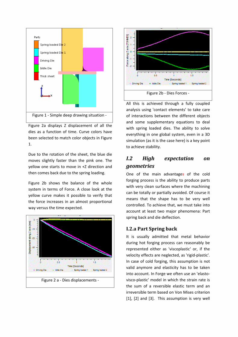
Figure 1 ‐ Simple deep drawing situation ‐
Figure 2a displays Z displacement of all the dies as a function of time. Curve colors have been selected to match color objects in Figure 1.
Due to the rotation of the sheet, the blue die moves slightly faster than the pink one. The yellow one starts to move in +Z direction and then comes back due to the spring loading.
Figure 2b shows the balance of the whole system in terms of Force. A close look at the yellow curve makes it possible to verify that the force increases in an almost proportional way versus the time expected.
Figure 2 a ‐ Dies displacements ‐
Figure 2b ‐ Dies Forces ‐
All this is achieved through a fully coupled analysis using 'contact elements' to take care of interactions between the different objects and some supplementary equations to deal with spring loaded dies. The ability to solve everything in one global system, even in a 3D simulation (as it is the case here) is a key point to achieve stability.
I.2 High expectation ongeometriesOne of the main advantages of the cold forging process is the ability to produce parts with very clean surfaces where the machining can be totally or partially avoided. Of course it means that the shape has to be very well controlled. To achieve that, we must take into account at least two major phenomena: Part spring back and die deflection.
I.2.aPartSpringbackIt is usually admitted that metal behavior during hot forging process can reasonably be represented either as 'viscoplastic' or, if the velocity effects are neglected, as 'rigid‐plastic'. In case of cold forging, this assumption is not valid anymore and elasticity has to be taken into account. In Forge we often use an 'elasto‐visco‐plastic' model in which the strain rate is the sum of a reversible elastic term and an irreversible term based on Von Mises criterion [1], [2] and [3]. This assumption is very well
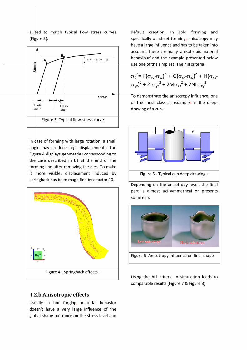
suited to match typical flow stress curves (Figure 3).
AB
Stre
ss
Strain
Plastic strain
Elastic strain
strain hardening
Figure 3: Typical flow stress curve
In case of forming with large rotation, a small angle may produce large displacements. The Figure 4 displays geometries corresponding to the case described in I.1 at the end of the forming and after removing the dies. To make it more visible, displacement induced by springback has been magnified by a factor 10.
Figure 4 ‐ Springback effects ‐
I.2.bAnisotropiceffectsUsually in hot forging, material behavior doesn't have a very large influence of the global shape but more on the stress level and
default creation. In cold forming and specifically on sheet forming, anisotropy may have a large influence and has to be taken into account. There are many 'anisotropic material behaviour' and the example presented below use one of the simplest: The hill criteria:
σ02= F(σyy‐σzz)2 + G(σxx‐σzz)2 + H(σxx‐
σyy)2 + 2Lσyz2 + 2Mσzx
2 + 2NLσxy2
To demonstrate the anisotropy influence, one of the most classical examples is the deep‐drawing of a cup.
Figure 5 ‐ Typical cup deep drawing ‐
Depending on the anisotropy level, the final part is almost axi‐symmetrical or presents some ears
Figure 6 ‐Anisotropy influence on final shape ‐
Using the hill criteria in simulation leads to comparable results (Figure 7 & Figure 8)
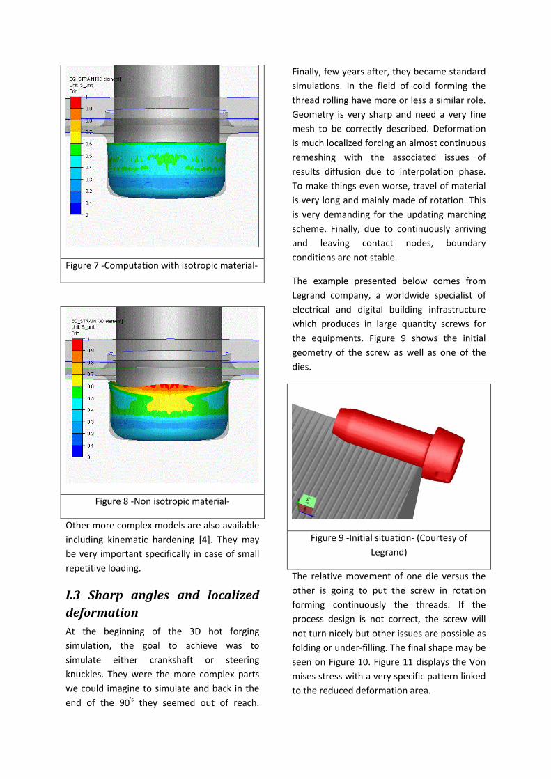
Figure 7 ‐Computation with isotropic material‐
Figure 8 ‐Non isotropic material‐
Other more complex models are also available including kinematic hardening [4]. They may be very important specifically in case of small repetitive loading.
I.3 Sharp angles and localizeddeformationAt the beginning of the 3D hot forging simulation, the goal to achieve was to simulate either crankshaft or steering knuckles. They were the more complex parts we could imagine to simulate and back in the end of the 90's they seemed out of reach.
Finally, few years after, they became standard simulations. In the field of cold forming the thread rolling have more or less a similar role. Geometry is very sharp and need a very fine mesh to be correctly described. Deformation is much localized forcing an almost continuous remeshing with the associated issues of results diffusion due to interpolation phase. To make things even worse, travel of material is very long and mainly made of rotation. This is very demanding for the updating marching scheme. Finally, due to continuously arriving and leaving contact nodes, boundary conditions are not stable.
The example presented below comes from Legrand company, a worldwide specialist of electrical and digital building infrastructure which produces in large quantity screws for the equipments. Figure 9 shows the initial geometry of the screw as well as one of the dies.
Figure 9 ‐Initial situation‐ (Courtesy of Legrand)
The relative movement of one die versus the other is going to put the screw in rotation forming continuously the threads. If the process design is not correct, the screw will not turn nicely but other issues are possible as folding or under‐filling. The final shape may be seen on Figure 10. Figure 11 displays the Von mises stress with a very specific pattern linked to the reduced deformation area.
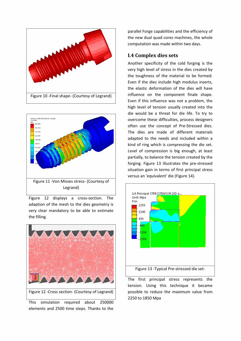
Figure 10 ‐Final shape‐ (Courtesy of Legrand)
Figure 11 ‐Von Misses stress‐ (Courtesy of Legrand)
Figure 12 displays a cross‐section. The adaption of the mesh to the dies geometry is very clear mandatory to be able to estimate the filling.
Figure 12 ‐Cross section‐ (Courtesy of Legrand)
This simulation required about 250000 elements and 2500 time steps. Thanks to the
parallel Forge capabilities and the efficiency of the new dual quad cores machines, the whole computation was made within two days.
I.4ComplexdiessetsAnother specificity of the cold forging is the very high level of stress in the dies created by the toughness of the material to be formed. Even if the dies include high modulus inserts, the elastic deformation of the dies will have influence on the component finale shape. Even if this influence was not a problem, the high level of tension usually created into the die would be a threat for die life. To try to overcome these difficulties, process designers often use the concept of Pre‐Stressed dies. The dies are made of different materials adapted to the needs and included within a kind of ring which is compressing the die set. Level of compression is big enough, at least partially, to balance the tension created by the forging. Figure 13 illustrates the pre‐stressed situation gain in terms of first principal stress versus an 'equivalent' die (Figure 14).
Figure 13 ‐Typical Pre‐stressed die set‐
The first principal stress represents the tension. Using this technique it became possible to reduce the maximum value from 2250 to 1850 Mpa
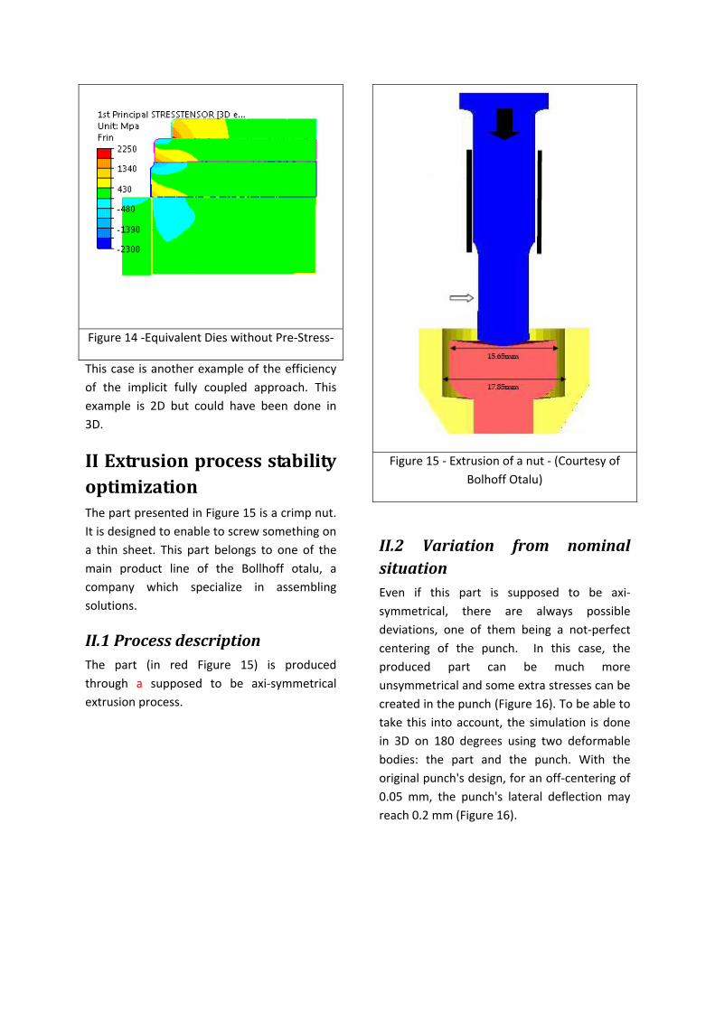
Figure 14 ‐Equivalent Dies without Pre‐Stress‐
This case is another example of the efficiency of the implicit fully coupled approach. This example is 2D but could have been done in 3D.
IIExtrusionprocessstabilityoptimizationThe part presented in Figure 15 is a crimp nut. It is designed to enable to screw something on a thin sheet. This part belongs to one of the main product line of the Bollhoff otalu, a company which specialize in assembling solutions.
II.1ProcessdescriptionThe part (in red Figure 15) is produced through a supposed to be axi‐symmetrical extrusion process.
Figure 15 ‐ Extrusion of a nut ‐ (Courtesy of Bolhoff Otalu)
II.2 Variation from nominalsituationEven if this part is supposed to be axi‐symmetrical, there are always possible deviations, one of them being a not‐perfect centering of the punch. In this case, the produced part can be much more unsymmetrical and some extra stresses can be created in the punch (Figure 16). To be able to take this into account, the simulation is done in 3D on 180 degrees using two deformable bodies: the part and the punch. With the original punch's design, for an off‐centering of 0.05 mm, the punch's lateral deflection may reach 0.2 mm (Figure 16).
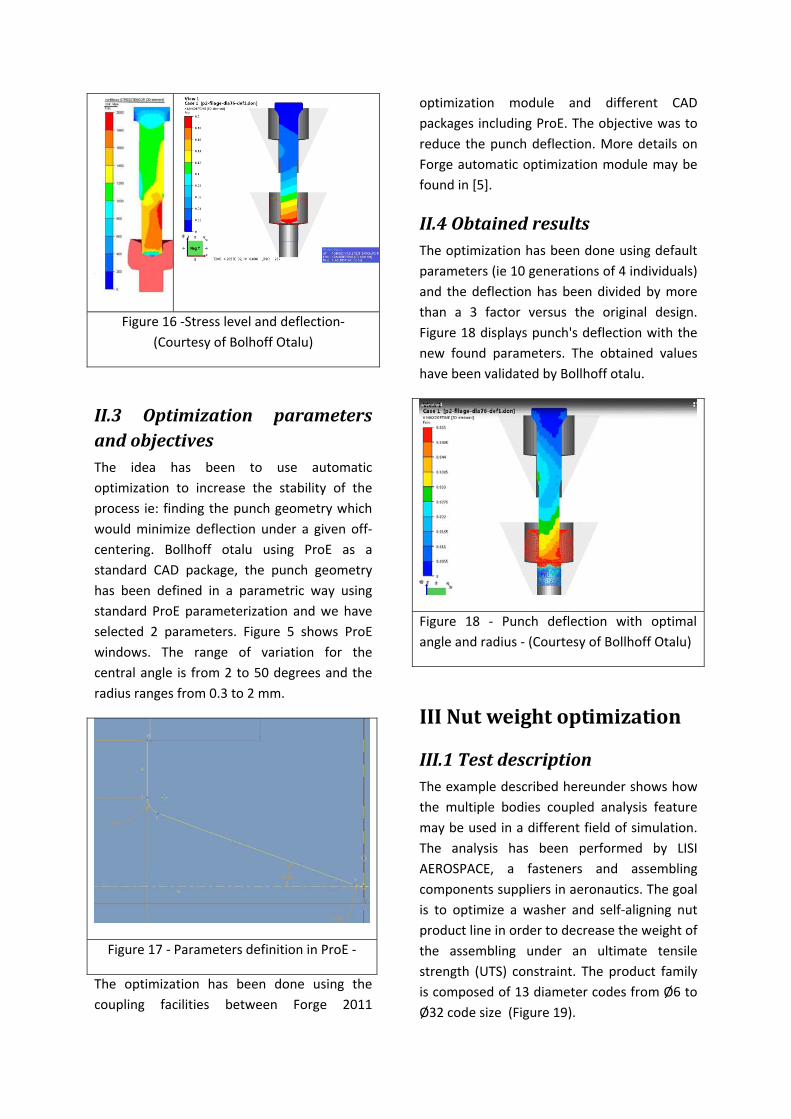
Figure 16 ‐Stress level and deflection‐ (Courtesy of Bolhoff Otalu)
II.3 Optimization parametersandobjectivesThe idea has been to use automatic optimization to increase the stability of the process ie: finding the punch geometry which would minimize deflection under a given off‐centering. Bollhoff otalu using ProE as a standard CAD package, the punch geometry has been defined in a parametric way using standard ProE parameterization and we have selected 2 parameters. Figure 5 shows ProE windows. The range of variation for the central angle is from 2 to 50 degrees and the radius ranges from 0.3 to 2 mm.
Figure 17 ‐ Parameters definition in ProE ‐
The optimization has been done using the coupling facilities between Forge 2011
optimization module and different CAD packages including ProE. The objective was to reduce the punch deflection. More details on Forge automatic optimization module may be found in [5].
II.4ObtainedresultsThe optimization has been done using default parameters (ie 10 generations of 4 individuals) and the deflection has been divided by more than a 3 factor versus the original design. Figure 18 displays punch's deflection with the new found parameters. The obtained values have been validated by Bollhoff otalu.
Figure 18 ‐ Punch deflection with optimal angle and radius ‐ (Courtesy of Bollhoff Otalu)
IIINutweightoptimization
III.1TestdescriptionThe example described hereunder shows how the multiple bodies coupled analysis feature may be used in a different field of simulation. The analysis has been performed by LISI AEROSPACE, a fasteners and assembling components suppliers in aeronautics. The goal is to optimize a washer and self‐aligning nut product line in order to decrease the weight of the assembling under an ultimate tensile strength (UTS) constraint. The product family is composed of 13 diameter codes from Ø6 to Ø32 code size (Figure 19).
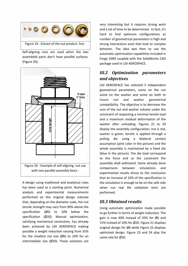
Figure 19 ‐ Extract of the nut product line ‐
Self‐aligning nuts are used when the two assembled parts don't have parallel surfaces. (Figure 20).
Figure 20 ‐ Example of self‐aligning nut use with non parallel assembly faces ‐
A design using traditional and analytical rules has been used as a starting point. Numerical analysis and experimental measurements performed on this original design indicate that, depending on the diameter code, the nut tensile strength may vary from 90% above the specification (Ø6) to 10% below the specification (Ø20). Manual optimization, satisfying mechanical constraints, has already been achieved by LISI AEROSPACE making possible a weight reduction varying from 35% for the smallest nut size (Ø6) to 10% for an intermediate size (Ø20). Those solutions are
very interesting but it requires strong work and a lot of time to be determined. In fact, it's hard to find optimum configurations as number of geometrical parameters is high and strong interactions exist that lead to complex behavior. The idea was then to use the automatic optimization capabilities included in Forge 2009 coupled with the SolidWorks CAD package used in LISI AEROSPACE.
III.2 Optimization parametersandobjectivesLISI AEROSPACE has selected 5 independent geometrical parameters, some on the nut some on the washer and some on both to insure nut and washer geometrical compatibility. The objective is to decrease the sum of the nut and washer volume under the constraint of respecting a minimal tensile load and a maximum residual deformation of the washer after unloading. Figures 21 to 24 display the assembly configuration: nut is red, washer is green, tensile is applied through a pulling die using a bilateral contact assumption (pink color in the picture) and the whole assembly is maintained by a fixed die (blue in the picture). The die load correspond to the force and so the constraint the assembly shall withstand. Some already done comparisons between simulations and experimental results drove to the conclusion that an increase of 10% of the specification in the simulation is enough to be on the safe side when nut real life validation tests are performed.
III.3ObtainedresultsUsing automatic optimization made possible to go further in terms of weight reduction. The gain is now 40% instead of 35% for Ø6 and 15% instead of 10% for Ø20. Figure 21 displays original design for Ø6 while Figure 22 displays optimized design. Figure 23 and 24 play the same role for Ø20.
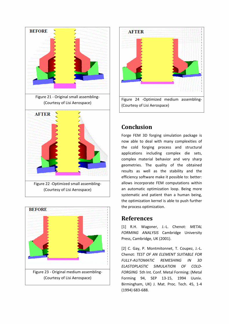
Figure 21 ‐ Original small assembling‐ (Courtesy of Lisi Aerospace)
Figure 22 ‐Optimized small assembling‐ (Courtesy of Lisi Aerospace)
Figure 23 ‐ Original medium assembling‐ (Courtesy of Lisi Aerospace)
Figure 24 ‐Optimized medium assembling‐ (Courtesy of Lisi Aerospace)
ConclusionForge FEM 3D forging simulation package is now able to deal with many complexities of the cold forging process and structural applications including complex die sets, complex material behavior and very sharp geometries. The quality of the obtained results as well as the stability and the efficiency software make it possible to: better: allows incorporate FEM computations within an automatic optimization loop. Being more systematic and patient than a human being, the optimization kernel is able to push further the process optimization.
References[1] R.H. Wagoner, J.‐L. Chenot: METAL FORMING ANALYSIS Cambridge University Press, Cambridge, UK (2001).
[2] C. Gay, P. Montmitonnet, T. Coupez, J.‐L. Chenot: TEST OF AN ELEMENT SUITABLE FOR FULLY‐AUTOMATIC REMESHING IN 3D ELASTOPLASTIC SIMULATION OF COLD‐FORGING 5th Int. Conf. Metal Forming: (Metal Forming 94, SEP 13‐15, 1994 Uuniv. Birmingham, UK) J. Mat. Proc. Tech. 45, 1‐4 (1994) 683‐688.
[3] P.O. De Micheli, K. Mocellin: A new efficient explicit formulation for linear tetrahedral elements non‐sensitive to volumetric locking for infinitesimal elasticity and inelasticity Int. J.Num. Methods Engg 79, 1 (2009) 45‐68
[4] Z.G. Liu, P. Lasne, E. Massony: Formability study of magnesium alloy AZ31B to be published in Numisheet 2011 proceedings
[5] L. Fourment, R. Ducloux, S. Marie, M. Ejday, D. Monnerau, T. Massé, P. Montmitonnet: Mono and multi‐objective optimization techniques applied to a large range of industrial test cases using Metamodel
assisted Evolutionary Algorithms Numiform 2010