Embed Size (px)
Citation preview
IMPROVEMENTS TO THE LHC SCHOTTKY MONITORS
M. Wendt∗, M. Betz, O.R. Jones, T. Lefevre, T. Levens, CERN, Geneva, Switzerland
Abstract
The LHC Schottky monitors have the potential to measure
and monitor some important beam parameters, e.g. tune,
momentum spread, chromaticity and emittance, in a non-
invasive way. We present recent upgrade and improvement
efforts of the transverse LHC Schottky systems operating at
4.81 GHz. This includes optimization of the slotted wave-
guide pickups and a re-design of the RF front-end electronics
to detect the weak, incoherent Schottky signals in presence
of large, coherent beam harmonics.
INTRODUCTION
The theory of bunched beam transverse Schottky signals
reveals the measurement of machine parameters, such as
tune, chromaticity, emittance, etc. based on the observa-
tion of coherent and incoherent motion of the bunched par-
ticles [1]. The associated dipole moment of each particle,
following betatron and synchrotron motion, can be expressed
as Fourier series, showing upper (usb) and lower (lsb) beta-
tron sidebands around each revolution harmonic h, which
further splits into synchrotron satellites.
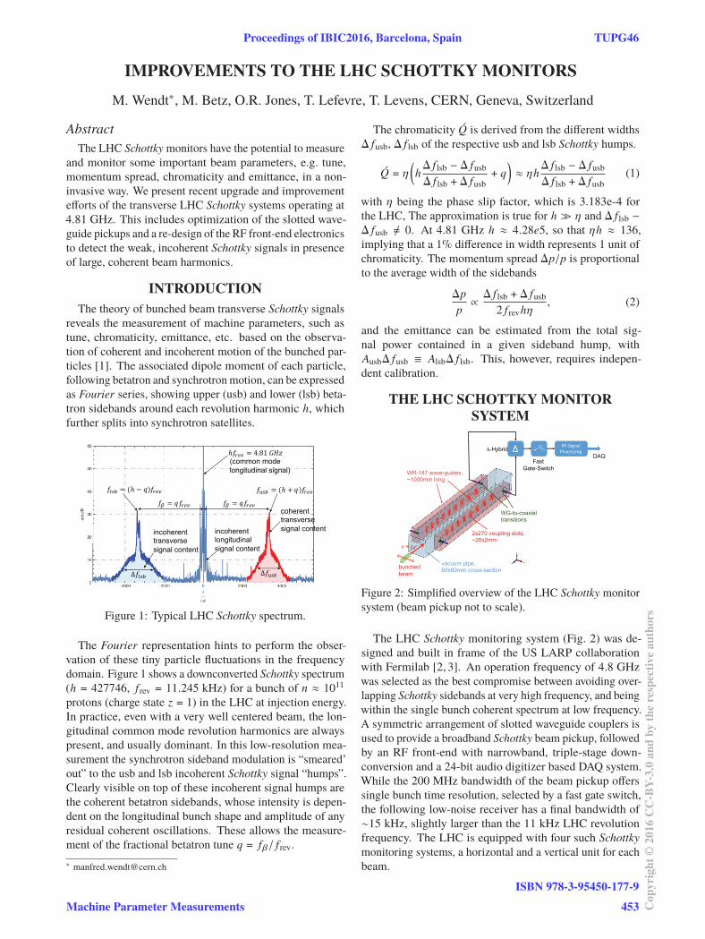
Figure 1: Typical LHC Schottky spectrum.
The Fourier representation hints to perform the obser-
vation of these tiny particle fluctuations in the frequency
domain. Figure 1 shows a downconverted Schottky spectrum
(h = 427746, f rev = 11.245 kHz) for a bunch of n ≈ 1011
protons (charge state z = 1) in the LHC at injection energy.
In practice, even with a very well centered beam, the lon-
gitudinal common mode revolution harmonics are always
present, and usually dominant. In this low-resolution mea-
surement the synchrotron sideband modulation is “smeared’
out” to the usb and lsb incoherent Schottky signal “humps”.
Clearly visible on top of these incoherent signal humps are
the coherent betatron sidebands, whose intensity is depen-
dent on the longitudinal bunch shape and amplitude of any
residual coherent oscillations. These allows the measure-
ment of the fractional betatron tune q = fβ/ f rev.
The chromaticity Q́ is derived from the different widths
Δ fusb, Δ f lsb of the respective usb and lsb Schottky humps.
Q́ = η(h
Δ f lsb − Δ fusb
Δ f lsb + Δ fusb+ q
)≈ ηh
Δ f lsb − Δ fusb
Δ f lsb + Δ fusb(1)
with η being the phase slip factor, which is 3.183e-4 for
the LHC, The approximation is true for h � η and Δ f lsb −
Δ fusb �= 0. At 4.81 GHz h ≈ 4.28e5, so that ηh ≈ 136,
implying that a 1% difference in width represents 1 unit of
chromaticity. The momentum spread Δp/p is proportional
to the average width of the sidebands
Δp
p∝
Δ f lsb + Δ fusb
2 f revhη, (2)
and the emittance can be estimated from the total sig-
nal power contained in a given sideband hump, with
AusbΔ fusb ≡ AlsbΔ f lsb. This, however, requires indepen-
dent calibration.
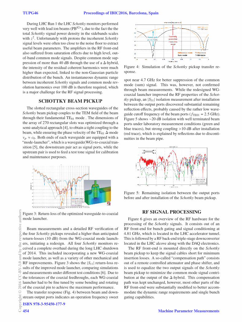
THE LHC SCHOTTKY MONITOR
SYSTEM
Figure 2: Simplified overview of the LHC Schottky monitor
system (beam pickup not to scale).
The LHC Schottky monitoring system (Fig. 2) was de-
signed and built in frame of the US LARP collaboration
with Fermilab [2, 3]. An operation frequency of 4.8 GHz
was selected as the best compromise between avoiding over-
lapping Schottky sidebands at very high frequency, and being
within the single bunch coherent spectrum at low frequency.
A symmetric arrangement of slotted waveguide couplers is
used to provide a broadband Schottky beam pickup, followed
by an RF front-end with narrowband, triple-stage down-
conversion and a 24-bit audio digitizer based DAQ system.
While the 200 MHz bandwidth of the beam pickup offers
single bunch time resolution, selected by a fast gate switch,
the following low-noise receiver has a final bandwidth of
∼15 kHz, slightly larger than the 11 kHz LHC revolution
frequency. The LHC is equipped with four such Schottky
monitoring systems, a horizontal and a vertical unit for each
beam.
Proceedings of IBIC2016, Barcelona, Spain TUPG46
Machine Parameter Measurements
ISBN 978-3-95450-177-9
453 Cop
yrig
ht©
2016
CC
-BY-
3.0
and
byth
ere
spec
tive
auth
ors
During LHC Run 1 the LHC Schottky monitors performed
very well with lead ion beams (PB82+), due to the fact the the
total Schottky signal power density in the sidebands scales
with z2. Unfortunately with protons the incoherent Schottky
signal levels were often too close to the noise floor to extract
useful beam parameters. The amplifiers in the RF front-end
also suffered from saturation effects due to high level, out-
of-band common mode signals. Despite common mode sup-
pression of more than 40 dB through the use of a Δ-hybrid,
the intensity of the residual coherent harmonics were much
higher than expected, linked to the non-Gaussian particle
distribution of the bunch. An instantaneous dynamic range
between incoherent Schottky signals and common mode rev-
olution harmonics over 100 dB is therefore required, which
is a major challenge for the RF signal processing.
SCHOTTKY BEAM PICKUP
The slotted rectangular cross-section waveguides of the
Schottky beam pickup couples to the TEM field of the beam
through their fundamental TE01 mode . The dimensions of
the array of 270 rectangular slots was optimized through a
semi-analytical approach [4], to obtain a tight coupling to the
beam, while ensuring the phase velocity of the TE01 Δ-mode
vp ≈ c0. Both ends of each waveguide are equipped with a
“mode-launcher”, which is a waveguide(WG)-to-coaxial tran-
sition [5], the downstream pair act as signal ports, while the
upstream pair is used to feed a test tone signal for calibration
and maintenance purposes.
Figure 3: Return-loss of the optimized waveguide-to-coaxial
mode launcher.
Beam measurements and a detailed RF verification of
the four Schottky pickups revealed a higher than anticipated
return-losses (10 dB) from the WG-coaxial mode launch-
ers, initiating a redesign. All four Schottky monitors re-
ceived a complete overhaul during the long LHC shutdown
of 2014. This included incorporating a new WG-coaxial
mode launcher, as well as a variety of other mechanical and
RF improvements. Figure 3 shows the |S11 | return-loss re-
sults of the improved mode launcher, comparing simulations
and measurements under different test conditions [6]. Due to
the tolerances of the coaxial feedhroughs, each WG-coaxial
launcher had to be fine tuned by some bending and rotating
of the coaxial pin to achieve the maximum performance.
The transfer response (Fig. 4) between beam and down-
stream output ports indicates an operation frequency sweet
Figure 4: Simulation of the Schottky pickup transfer re-
sponse.
spot near 4.7 GHz for better suppression of the common
mode (sum) signal. This was, however, not confirmed
through beam measurements. While the redesigned WG-
coaxial launcher improved the RF properties of the Schot-
tky pickup, an |S31 | isolation measurement after installation
between the output ports discovered substantial remaining
reflection effects, probably caused by the rather low wave-
guide cutoff frequency of the beam ports ( fTE01 = 2.5 GHz).
Figure 5 shows ∼20 dB isolation with well terminated beam
ports under laboratory measurement conditions (green and
blue traces), but strong coupling >10 dB after installation
(red trace), which is explained by reflections due to disconti-
nuities in the beam pipe.
Figure 5: Remaining isolation between the output ports
before and after installation of the Schottky beam pickup.
RF SIGNAL PROCESSING
Figure 6 gives an overview of the RF hardware for the
processing of the Schottky signals. It consists out of an
RF front-end for bunch gating and signal conditioning at
4.81 GHz, which is located in the LHC accelerator tunnel.
This is followed by a RF back-end triple-stage downconverter
located in the LHC alcove along with the DAQ electronics.
The RF front-end is mounted directly on the Schottky
beam pickup to keep the signal cables short for minimum
insertion losses. A so-called “compensation path” consists
out of a remote controlled attenuator and phase shifter, and
is used to equalize the two output signals of the Schottky
beam pickup to minimize the common mode signal contri-
bution at the output of the Δ-hybrid. This compensation
path was kept unchanged, however, most other parts of the
RF front-end were substantially modified to better accom-
modate the dynamic range requirements and single bunch
gating capabilities.
TUPG46 Proceedings of IBIC2016, Barcelona, Spain
ISBN 978-3-95450-177-9
454Cop
yrig
ht©
2016
CC
-BY-
3.0
and
byth
ere
spec
tive
auth
ors
Machine Parameter Measurements
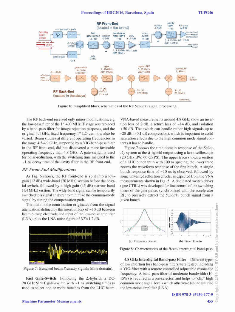
Figure 6: Simplified block schematics of the RF Schottky signal processing.
The RF back-end received only minor modifications, e.g.
the low-pass filter of the 1st 400 MHz IF stage was replaced
by a band-pass filter for image rejection purposes, and the
original 4.4 GHz fixed frequency 1st LO can now also be
varied. Beam studies at different operating frequencies in
the range 4.5-4.9 GHz, supported by a YIG band-pass filter
in the RF front-end, did not discovered a more favorable
operating frequency than 4.8 GHz. A gate-switch is used
for noise-reduction, with the switching time matched to the
∼1 μs decay time of the cavity filter in the RF front-end.
RF Front-End Modifications
As Fig. 6 shows, the RF front-end is split into a low-
gain (12 dB) wide-band (70 MHz) section before the coax-
ial switch, followed by a high-gain (45 dB) narrow-band
(1.4 MHz) section. The wide-band signal can be temporarily
switched to a signal analyzer to minimize the common-mode
signal by tuning the compensation path.
The main noise contribution originates from the signal
attenuation, defined by the insertion loss of ∼10 dB between
beam pickup electrode and input of the low-noise amplifier
(LNA), plus the LNA noise figure of NF≈1.2 dB.
Figure 7: Bunched beam Schottky signals (time domain).
Fast Gate-Switch Following the Δ-hybrid, a DC-
28 GHz SPDT gate-switch with ∼1 ns switching times is
used to select one or more bunches from the LHC beam.
VNA-based measurements around 4.8 GHz show an inser-
tion loss of 2 dB, a return loss of ∼14 dB, and isolation
>50 dB. The switch can handle rather high signals up to
+20 dBm (0.1 dB compression), which is important to avoid
saturation effects due to the high common mode signal con-
tents it has to handle.
Figure 7 shows the time domain response of the Schot-
tky system at the Δ-hybrid output using a fast oscilloscope
(20 GHz BW, 60 GSPS). The upper trace shows a section
of a LHC bunch train with 100 ns spacing, the lower trace
zooms the waveform response of the first bunch. A single
bunch response time of ∼10 ns is observed, followed by
some unwanted reflection effects, as expected from the VNA
measurements shown in Fig. 5. A dedicated switch driver
(gate CTRL) was developed for fine control of the switching
times of the gate pulse, synchronized with the accelerator
RF, to precisely extract the Schottky bunch signal from a
given bunch.
(a) Frequency domain (b) Time Domain
Figure 8: Characteristics of the Bessel interdigital band-pass.
4.8 GHz Interdigital Band-pass Filter Different types
of low insertion loss band-pass filters were tested, including
a YIG-filter with a remote controlled adjustable resonance
frequency. A band-pass filter of moderate bandwidth (10-
15%) is required as a pre-selector, and helps to “clip” high
common mode signal levels which otherwise tend to saturate
the low-noise amplifier (LNA).
Proceedings of IBIC2016, Barcelona, Spain TUPG46
Machine Parameter Measurements
ISBN 978-3-95450-177-9
455 Cop
yrig
ht©
2016
CC
-BY-
3.0
and
byth
ere
spec
tive
auth
ors
A self-built 2-stage Bessel band-pass filter, based on in-
terdigital airline resonators [7] was found to be a good com-
promise in terms of insertion loss, selectivity, and impulse
response. Figure 8 (a) compares the measured and simu-
lated |S21( f )| transfer function, while Fig. 8 (b) shows the
corresponding measured time-domain response s21(t). With
a total decay time of 5τ ≈ 25 ns, this design gives some
flexibility to locate this filter either before or after the fast
gate-switch.
4.8 GHz Cavity Band-pass Filter After gating, there
is no need for a ns-scale time resolution, hence narrow-
band filtering was applied to minimize integrated spectral
power. A modified pill-box cavity was used as a single stage
bandpass filter with a bandwidth of < 0.03 %.
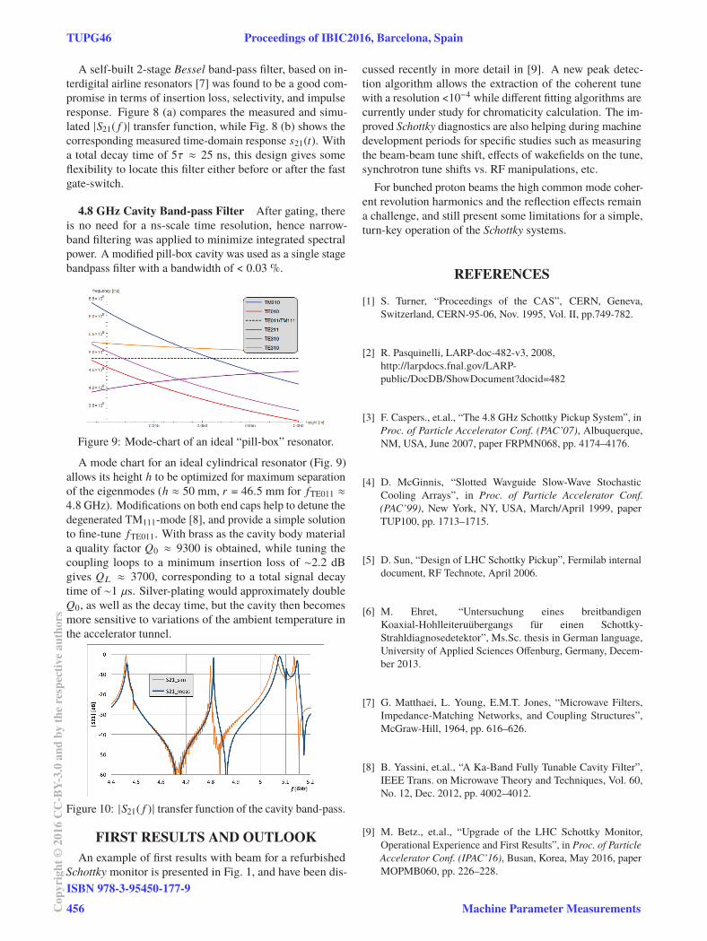
Figure 9: Mode-chart of an ideal “pill-box” resonator.
A mode chart for an ideal cylindrical resonator (Fig. 9)
allows its height h to be optimized for maximum separation
of the eigenmodes (h ≈ 50 mm, r = 46.5 mm for fTE011 ≈
4.8 GHz). Modifications on both end caps help to detune the
degenerated TM111-mode [8], and provide a simple solution
to fine-tune fTE011. With brass as the cavity body material
a quality factor Q0 ≈ 9300 is obtained, while tuning the
coupling loops to a minimum insertion loss of ∼2.2 dB
gives QL ≈ 3700, corresponding to a total signal decay
time of ∼1 μs. Silver-plating would approximately double
Q0, as well as the decay time, but the cavity then becomes
more sensitive to variations of the ambient temperature in
the accelerator tunnel.
Figure 10: |S21( f )| transfer function of the cavity band-pass.
FIRST RESULTS AND OUTLOOK
An example of first results with beam for a refurbished
Schottky monitor is presented in Fig. 1, and have been dis-
cussed recently in more detail in [9]. A new peak detec-
tion algorithm allows the extraction of the coherent tune
with a resolution <10−4 while different fitting algorithms are
currently under study for chromaticity calculation. The im-
proved Schottky diagnostics are also helping during machine
development periods for specific studies such as measuring
the beam-beam tune shift, effects of wakefields on the tune,
synchrotron tune shifts vs. RF manipulations, etc.
For bunched proton beams the high common mode coher-
ent revolution harmonics and the reflection effects remain
a challenge, and still present some limitations for a simple,
turn-key operation of the Schottky systems.
REFERENCES
[1] S. Turner, “Proceedings of the CAS”, CERN, Geneva,
Switzerland, CERN-95-06, Nov. 1995, Vol. II, pp.749-782.
[2] R. Pasquinelli, LARP-doc-482-v3, 2008,
http://larpdocs.fnal.gov/LARP-
public/DocDB/ShowDocument?docid=482
[3] F. Caspers., et.al., “The 4.8 GHz Schottky Pickup System”, in
Proc. of Particle Accelerator Conf. (PAC’07), Albuquerque,
NM, USA, June 2007, paper FRPMN068, pp. 4174–4176.
[4] D. McGinnis, “Slotted Wavguide Slow-Wave Stochastic
Cooling Arrays”, in Proc. of Particle Accelerator Conf.
(PAC’99), New York, NY, USA, March/April 1999, paper
TUP100, pp. 1713–1715.
[5] D. Sun, “Design of LHC Schottky Pickup”, Fermilab internal
document, RF Technote, April 2006.
[6] M. Ehret, “Untersuchung eines breitbandigen
Koaxial-Hohlleiteruübergangs für einen Schottky-
Strahldiagnosedetektor”, Ms.Sc. thesis in German language,
University of Applied Sciences Offenburg, Germany, Decem-
ber 2013.
[7] G. Matthaei, L. Young, E.M.T. Jones, “Microwave Filters,
Impedance-Matching Networks, and Coupling Structures”,
McGraw-Hill, 1964, pp. 616–626.
[8] B. Yassini, et.al., “A Ka-Band Fully Tunable Cavity Filter”,
IEEE Trans. on Microwave Theory and Techniques, Vol. 60,
No. 12, Dec. 2012, pp. 4002–4012.
[9] M. Betz., et.al., “Upgrade of the LHC Schottky Monitor,
Operational Experience and First Results”, in Proc. of Particle
Accelerator Conf. (IPAC’16), Busan, Korea, May 2016, paper
MOPMB060, pp. 226–228.
TUPG46 Proceedings of IBIC2016, Barcelona, Spain
ISBN 978-3-95450-177-9
456Cop
yrig
ht©
2016
CC
-BY-
3.0
and
byth
ere
spec
tive
auth
ors
Machine Parameter Measurements