Embed Size (px)
Citation preview
Improvement of the Polaris FST Switchback:
Staying Flexible for a Greener Tomorrow
Derek M. Frie, Robert M.A. Haack, Clayton M. Hendricks, Alexander M. Hetteen, Daniel D. Rahman, Andrew B. Wichlacz, Dr. Jason R. Blough
Michigan Technological University
Copyright © 2009 SAE International
ABSTRACT
From 2001 to 2006, the Michigan Technological University Clean Snowmobile Team successfully implemented high-performance four-cycle internal combustion engines into an existing snowmobile chassis. The team’s complications in past years did not rise from using a four-stroke engine in a snowmobile. Problems arose from the simple fact that all previous engines were originally motorcycle engines which did not have dimensions or configurations consistent with that of a snowmobile engine. This led to difficulties in packaging, drive train modifications, and additional weight. In 2007, the team decided to take a different approach in building a snowmobile for the competition. Instead of spending significant effort on engineering the cohesion between engine and chassis, the team decided to start with a stock snowmobile engine and chassis. Our OEM snowmobile choice for 2007 and 2008 was the 2006 Polaris FST Classic. Polaris released an improved chassis in 2008 in the form of the FST Switchback. The team decided to utilize this chassis due to chassis advancements and packaging advantages over the 2006 Polaris FST Classic. The use of a stock engine and chassis combination allowed for a greater focus to be placed on the implementation and calibration of a flex fuel system. This configuration along with the use of team-designed exhaust and intake systems has made significant reductions in emissions and noise possible. The net result is a snowmobile that is not only environmentally friendly, but also a pleasure to ride.
INTRODUCTION
Due to rising environmental concerns regarding the use of snowmobiles in Yellowstone National Park, the Clean Snowmobile Challenge was introduced in the winter of 2000 in Jackson Hole, Wyoming. This event was sponsored by the Society of Automotive Engineers (SAE), and consisted of universities from across the United States and Canada, all of which arrived with snowmobiles that they had designed and built. The snowmobiles were evaluated in several static and dynamic events, including acceleration, handling, and hill climb events. In 2003, the competition moved to the Upper
Peninsula of Michigan and was hosted by the Keweenaw Research Center (KRC) just north of Michigan Technological University’s (MTU’s) campus. For 2009, the competition remains at the KRC and runs from March 16th to the 21st, and will feature snowmobiles propelled by internal combustion engines, gas-electric hybrids and zero-emissions electric motors.
Michigan Tech’s team is composed of 37 members from various educational disciplines including Mechanical Engineering, Mechanical Engineering Technology, Civil Engineering, and Business. The team is divided into five sub-teams: engine, chassis, drive train, modeling and data acquisition, and business. The first four of these teams are focused primarily on the design and fabrication of the snowmobile. The business team, however, is dedicated to public and sponsor relations as well as team dynamics.
For 2009, the team focused on improving the overall performance as well as reducing the weight of the snowmobile. The goals were to improve horsepower by 20% and reduce weight by 7% compared to the 2008 MTU entry. Refer to Table 1.0 for a comprehensive analysis of the 2008 MTU competition results. Based on these results, the team formulated a list of goals for 2009 which can be seen in Table 2.0.
Table 1.0: This table displays the 2008 MTU Clean Snowmobile competition results.
Event Score Place
(Out of 12)Design Paper 62.7/100 4 Static Display 50/50 MSRP 16.9/50 11 Subjective Handling 24.21/50 6 Fuel Economy 0/200 6 Oral Presentation 39.8/100 4 Noise 178.3/300 5
Acceleration 83.3/100 3 Emissions 281/300 2 Cold Start 0/50 Objective Handling 33.7/75 8 Penalties/Bonuses -40 Weight 6/100 10 Overall 736/1475 4
Table 2.0: This table compares the MTU CSC goals from 2008 to 2009.
PERFORMANCE BY INNOVATION
The 2009 MTU Clean Snowmobile is not only clean and quiet, but also a lighter and more powerful machine than the 2008 entry. This makes the ride more enjoyable and closely replicates stock four-stroke snowmobiles. The increased fuel economy, reliability, and lower maintenance than two-stroke snowmobiles has significantly increased the popularity of four-stroke snowmobiles.
The 2009 MTU entry appears to closely resemble a stock Polaris snowmobile. Through careful planning the ergonomics of the snowmobile remained similar to that of the OEM model. However, new technologies such as engine modifications, exhaust and intake systems design, tunnel design, suspension modifications, and engine calibration were implemented into the 2009 entry.
Table 3.0 shows a list of components and equipment specifications used to meet the 2009 goals of the MTU Clean Snowmobile team. Key vehicle components include chassis, engine, fuel, intake, exhaust, drive train, track, and suspension systems.
Table 3.0: This table specifies various snowmobile components found on the 2009 MTU Clean Snowmobile.
Component Description Chassis 2008 Polaris FST Switchback Engine 750 cc Weber Parallel Twin Four-Stroke
Fuel System AEM Fuel Management System, Mallory 4060FI Competition Fuel Pump
Intake System
Intercooler: MTU Clean Snowmobile Designed and Fabricated Air to Air
Intake Plenum: MTU Clean Snowmobile Designed and Fabricated
Exhaust System
Turbo: IHI RHB-51 Exhaust Header: MTU Clean Snowmobile Designed and Fabricated 321 Stainless Steel 2-1 System Catalyst: V-Converter 3-way Catalyst Muffler: MTU Clean Snowmobile Designed Expansion Chamber Muffler
Drive Train Primary Drive: Polaris OEM P-85 Secondary Drive: OEM Team Rapid Reaction Roller Secondary
Suspension
Front Suspension: MTU Designed and Fabricated Aluminum A-arms Rear Suspension: MTU Clean Snowmobile Modified Ski-Doo SC-5
Track 120"x1.352"x15" Camoplast Cobra
ENGINE
The Weber 750 cc engine was a prime choice for the 2009 competition snowmobile since it was the original engine in the Polaris FST and the team has extensive experience with it from past years. Through countless hours of testing and tuning, it has been proven to be a very tolerant and reliable engine which makes it an ideal candidate for flex fuel implementation. Head Rotation The Weber 750 cc multi-purpose engine has a symmetrical cylinder head design that allows the engine to run properly while the head is rotated 180°. This switches the location of the intake and exhaust ports. The rotation is made possible due to the design of the Weber engine using a central timing chain located between the power take off (PTO) and magneto (MAG) cylinders. In order to reverse the head, a different camshaft and coolant rail is also required. In the stock Polaris configuration, the intake ports face the gas tank while the exhaust is routed forward under the hood. The configuration used in the MTU 2009 entry is rotated 180° from this stock orientation. This allows more room for intake packaging as well as the entire length of the tunnel for the exhaust system.
2008 Goals 2009 Goals Increase engine power output from the 2007 design to better replicate the stock FST
Increase horsepower from the 2008 design by 20%
Pass 2012 EPA emissions regulations while using E-85, as well as surpassing the 2007 entry’s emissions
Pass 2012 EPA emissions regulations while using flex fuel, as well as surpassing all other 2009 entry’s emissions
Achieve a sound pressure level lower than 74 dBA per SAE J192 specification
Achieve a sound pressure level lower than 73 dBA per SAE J192 specification
Reduce overall vehicle weight as well as maintain relatively stock ergonomics
Reduce overall vehicle weight by 7% while maintaining stock ergonomics and appearance
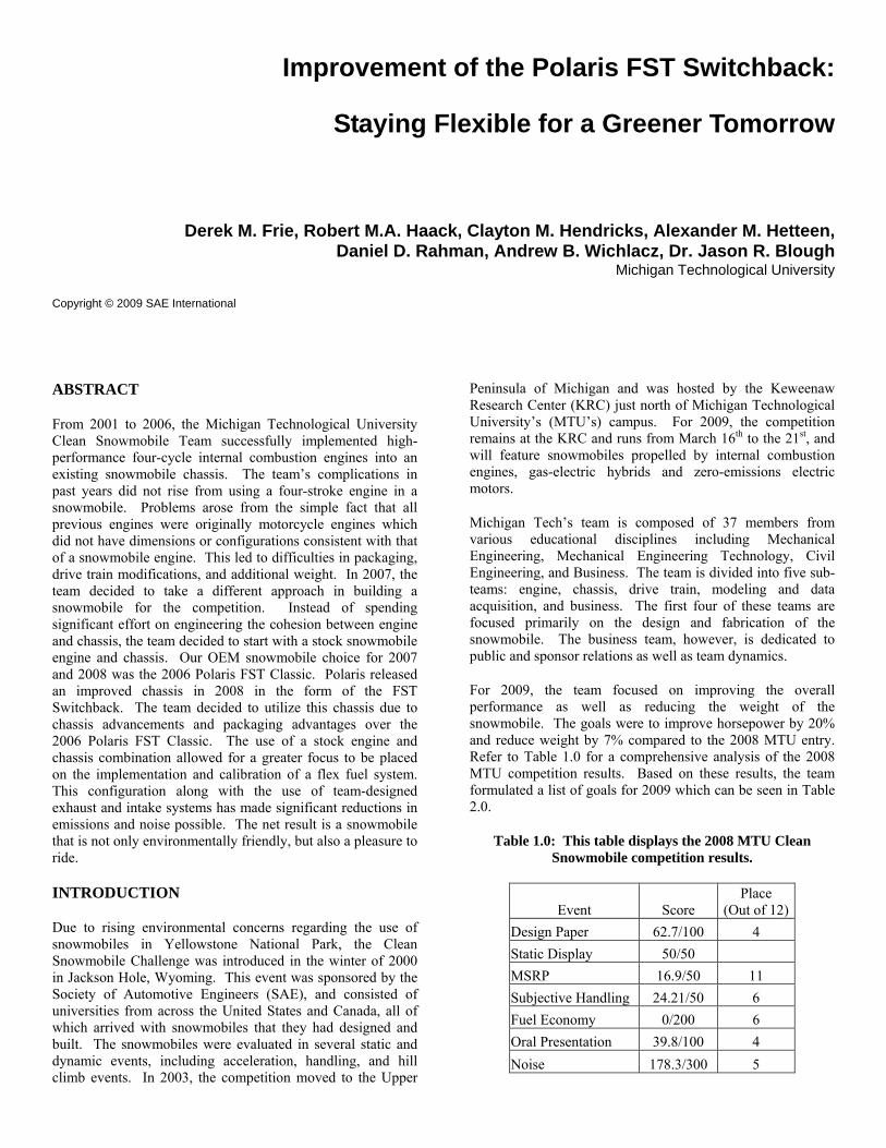
Intake Due to the implementation of the head rotation, a new intake system had to be designed and fabricated to fit under the hood. The first consideration was the design of the intake plenum. Through modeling and data analysis a few key design constraints were established. The first constraint was the position of the inlet pipe on the plenum. Through research and analysis, it was found that a center inlet on the plenum would result in a more balanced flow of air into each cylinder resulting in a greater efficiency. This can be seen in the following figures. Figure 1.0 shows the air flow of a side inlet intake plenum running at low engine speed. Figure 1.1 shows the same side inlet intake plenum running at high engine speed. [1] The red lines indicate a starvation of air to the cylinder while the blue lines indicate excessive air flow to the cylinder.
Figure 1.0: This figure displays the air flow of a side inlet intake plenum operating at low engine speeds.
Figure 1.1: This figure displays the air flow of a side inlet intake plenum operating at high engine speeds.
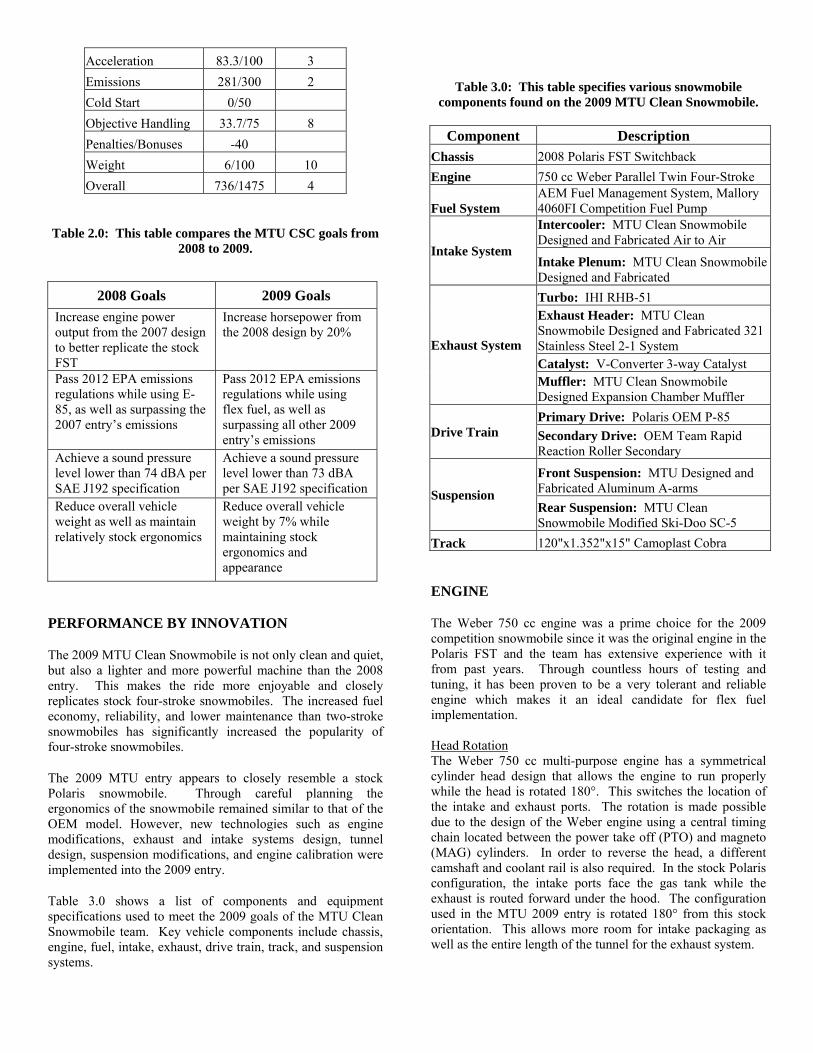
Figure 1.2 shows a center inlet intake plenum. [1] This allows the air to be more evenly distributed into each cylinder causing all the cylinders to get the same amount of air and run at peak efficiency and power. Although these models represent a six-cylinder engine, the same trend can be applied to the Weber 750 cc two-cylinder engine even though the effects are not as drastic.
Figure 1.2: This figure displays the air flow of a center inlet intake plenum.
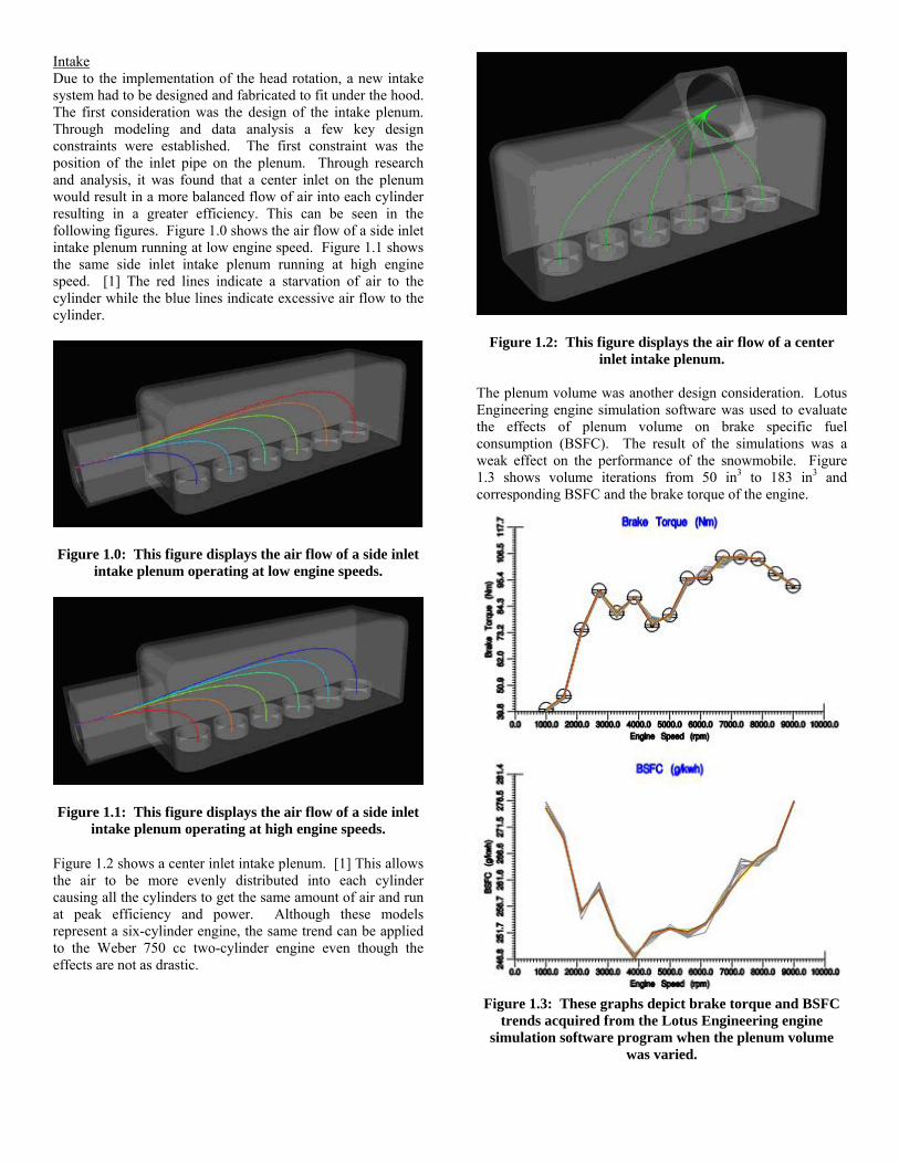
The plenum volume was another design consideration. Lotus Engineering engine simulation software was used to evaluate the effects of plenum volume on brake specific fuel consumption (BSFC). The result of the simulations was a weak effect on the performance of the snowmobile. Figure 1.3 shows volume iterations from 50 in3 to 183 in3 and corresponding BSFC and the brake torque of the engine.
Figure 1.3: These graphs depict brake torque and BSFC
trends acquired from the Lotus Engineering engine simulation software program when the plenum volume
was varied.

From these models it can be seen that there is little effect to the BSFC or brake torque when the plenum volume is increased. This data was used to justify reducing the plenum volume from 141.52 in3 in 2008 to 125.7 in3 in the 2009 design. The decreased size was necessary for improved packaging. Another area that was improved upon over the 2008 design was the entrance to the throttle bodies. Bell-mouth entrances were utilized to reduce the flow losses when air enters the throttle bodies from the plenum. As can be seen in the graph of Figure 1.4, eliminating the reentrant entrance and implementing the bell-mouth entrance, the flow loss coefficient can be reduced from approximately 0.78 to 0.04.
Figure 1.4: These graphs compare flow loss coefficients
for various entrance types. Through simulations conducted in a senior design project by two MTU Clean Snowmobile members, it was determined that the runner length had the most affect on the efficiency of the intake system. This affect can be seen in the graphs of brake torque and BSFC of the engine shown in Figure 1.5. From the trends seen in these graphs, lengthening the runners increased performance over a wide rpm range. The runners in the new design were lengthened to 4.5” from the previous year’s length of 3.75”. This length was chosen to properly fit the plenum under the hood as well as maximize efficiency.
Figure 1.5: These graphs depict brake torque and BSFC
trends acquired from the Lotus Engineering engine simulation software program when the runner length was
varied.
Turbocharger The stock turbocharger from the Polaris FST could not be used because it has a cast turbo header. A turbocharger from IHI was selected which allowed flexible positioning. The turbo chosen was an IHI RHB51 which is similar in size, shape and performance to the stock turbocharger. The header was fabricated using 321 stainless steel for long term durability against dynamic and thermal loading. The down pipe and O2 sensor housing were manufactured with 304 stainless steel for corrosion resistance. Intercooler The intercooler’s main function is to decrease the temperature of the intake air. As air temperature decreases, it becomes denser. This trend can be seen in Figure 2.0. This increase in density means that there is a higher mass of air per unit volume. With the increase in the amount of air drawn into the engine, the volumetric efficiency of the engine will increase which can be shown with Equation 1.
,
av
a i d
mnVρ
=⋅
(1)
nv= Volumetric Efficiency ma=Mass of Air ρa,i=Density of Air Vd=Displaced Volume
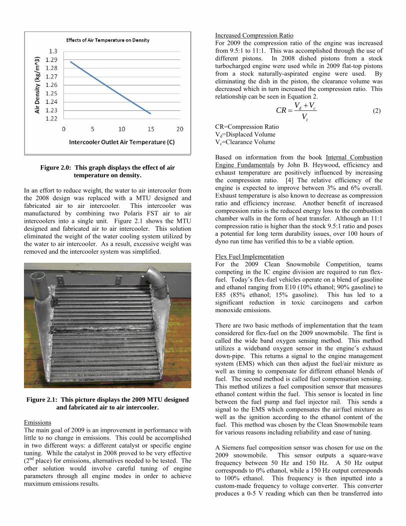
Figure 2.0: This graph displays the effect of air temperature on density.
In an effort to reduce weight, the water to air intercooler from the 2008 design was replaced with a MTU designed and fabricated air to air intercooler. This intercooler was manufactured by combining two Polaris FST air to air intercoolers into a single unit. Figure 2.1 shows the MTU designed and fabricated air to air intercooler. This solution eliminated the weight of the water cooling system utilized by the water to air intercooler. As a result, excessive weight was removed and the intercooler system was simplified.
Figure 2.1: This picture displays the 2009 MTU designed
and fabricated air to air intercooler. Emissions The main goal of 2009 is an improvement in performance with little to no change in emissions. This could be accomplished in two different ways: a different catalyst or specific engine tuning. While the catalyst in 2008 proved to be very effective (2nd place) for emissions, alternatives needed to be tested. The other solution would involve careful tuning of engine parameters through all engine modes in order to achieve maximum emissions results.
Increased Compression Ratio For 2009 the compression ratio of the engine was increased from 9.5:1 to 11:1. This was accomplished through the use of different pistons. In 2008 dished pistons from a stock turbocharged engine were used while in 2009 flat-top pistons from a stock naturally-aspirated engine were used. By eliminating the dish in the piston, the clearance volume was decreased which in turn increased the compression ratio. This relationship can be seen in Equation 2.
d c
c
V VCRV+
= (2)
CR=Compression Ratio Vd=Displaced Volume Vc=Clearance Volume Based on information from the book Internal Combustion Engine Fundamentals by John B. Heywood, efficiency and exhaust temperature are positively influenced by increasing the compression ratio. [4] The relative efficiency of the engine is expected to improve between 3% and 6% overall. Exhaust temperature is also known to decrease as compression ratio and efficiency increase. Another benefit of increased compression ratio is the reduced energy loss to the combustion chamber walls in the form of heat transfer. Although an 11:1 compression ratio is higher than the stock 9.5:1 ratio and poses a potential for long term durability issues, over 100 hours of dyno run time has verified this to be a viable option. Flex Fuel Implementation For the 2009 Clean Snowmobile Competition, teams competing in the IC engine division are required to run flex-fuel. Today’s flex-fuel vehicles operate on a blend of gasoline and ethanol ranging from E10 (10% ethanol; 90% gasoline) to E85 (85% ethanol; 15% gasoline). This has led to a significant reduction in toxic carcinogens and carbon monoxide emissions. There are two basic methods of implementation that the team considered for flex-fuel on the 2009 snowmobile. The first is called the wide band oxygen sensing method. This method utilizes a wideband oxygen sensor in the engine’s exhaust down-pipe. This returns a signal to the engine management system (EMS) which can then adjust the fuel/air mixture as well as timing to compensate for different ethanol blends of fuel. The second method is called fuel compensation sensing. This method utilizes a fuel composition sensor that measures ethanol content within the fuel. This sensor is located in line between the fuel pump and fuel injector rail. This sends a signal to the EMS which compensates the air/fuel mixture as well as the ignition according to the ethanol content of the fuel. This method was chosen by the Clean Snowmobile team for various reasons including reliability and ease of tuning. A Siemens fuel composition sensor was chosen for use on the 2009 snowmobile. This sensor outputs a square-wave frequency between 50 Hz and 150 Hz. A 50 Hz output corresponds to 0% ethanol, while a 150 Hz output corresponds to 100% ethanol. This frequency is then inputted into a custom-made frequency to voltage converter. This converter produces a 0-5 V reading which can then be transferred into
the EMS. The AEM EMS used on the 2009 snowmobile does not have a provision for flex-fuel. Therefore, the voltage is inputted into a generic AEM input. This configuration allows the EMS to add/subtract fuel from the current fuel map based on a 0-5 V input. The EMS, however, is not able to adjust the ignition map. The Weber 750 cc engine is very tolerant throughout a wide range of ignition advance without detonation or knock. Based on this observation, the ignition advance map will be tuned so that it is tolerant of any ethanol blend. A knock sensor is being utilized to detect knock or detonation which will then compensate the ignition. For the 2008 competition, the snowmobile was tuned on E85. A modified version of this map was used as the reference point for flex-fuel compensation. From this base map, the fuel trim system compensates based on the 0-5 V input. Table 4.0 shows the control algorithm for the system. If the fuel’s ethanol content falls outside or between values listed in the table, the processor in the AEM EMS will automatically interpolate and extrapolate based on a system of averages. This control algorithm is based upon stoichiometric air/fuel ratios for the various ethanol blends. This ratio is important because it provides proper, detonation-free combustion.
Table 4.0: This table displays the AEM EMS fuel trim table used for flex fuel implementation.
Input (V) Ethanol
Content (%) Adjustment (%)0 0.00 -30.00
0.3125 6.25 -27.340.625 12.50 -25.70
0.9375 18.75 -24.221.25 25.00 -22.27
1.5625 31.25 -20.701.875 37.50 -18.75
2.1875 43.75 -16.402.5 50.00 -14.45
2.8125 56.25 -12.103.125 62.50 -9.75
3.4375 68.75 -7.453.75 75.00 -4.70
4.0625 81.25 -1.554.375 87.50 1.15
4.6875 93.75 4.705 100.00 8.20
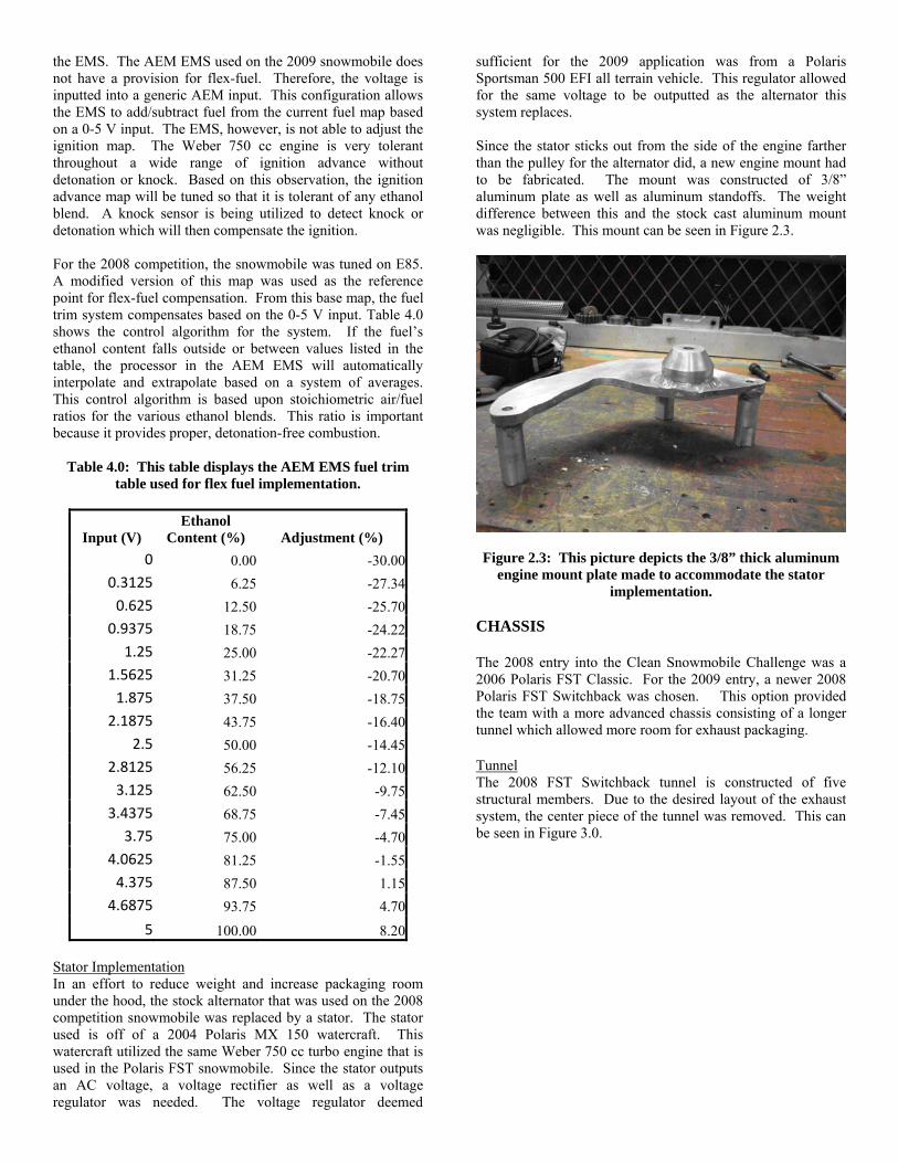
Stator Implementation In an effort to reduce weight and increase packaging room under the hood, the stock alternator that was used on the 2008 competition snowmobile was replaced by a stator. The stator used is off of a 2004 Polaris MX 150 watercraft. This watercraft utilized the same Weber 750 cc turbo engine that is used in the Polaris FST snowmobile. Since the stator outputs an AC voltage, a voltage rectifier as well as a voltage regulator was needed. The voltage regulator deemed
sufficient for the 2009 application was from a Polaris Sportsman 500 EFI all terrain vehicle. This regulator allowed for the same voltage to be outputted as the alternator this system replaces. Since the stator sticks out from the side of the engine farther than the pulley for the alternator did, a new engine mount had to be fabricated. The mount was constructed of 3/8” aluminum plate as well as aluminum standoffs. The weight difference between this and the stock cast aluminum mount was negligible. This mount can be seen in Figure 2.3.
Figure 2.3: This picture depicts the 3/8” thick aluminum engine mount plate made to accommodate the stator
implementation.
CHASSIS The 2008 entry into the Clean Snowmobile Challenge was a 2006 Polaris FST Classic. For the 2009 entry, a newer 2008 Polaris FST Switchback was chosen. This option provided the team with a more advanced chassis consisting of a longer tunnel which allowed more room for exhaust packaging. Tunnel The 2008 FST Switchback tunnel is constructed of five structural members. Due to the desired layout of the exhaust system, the center piece of the tunnel was removed. This can be seen in Figure 3.0.
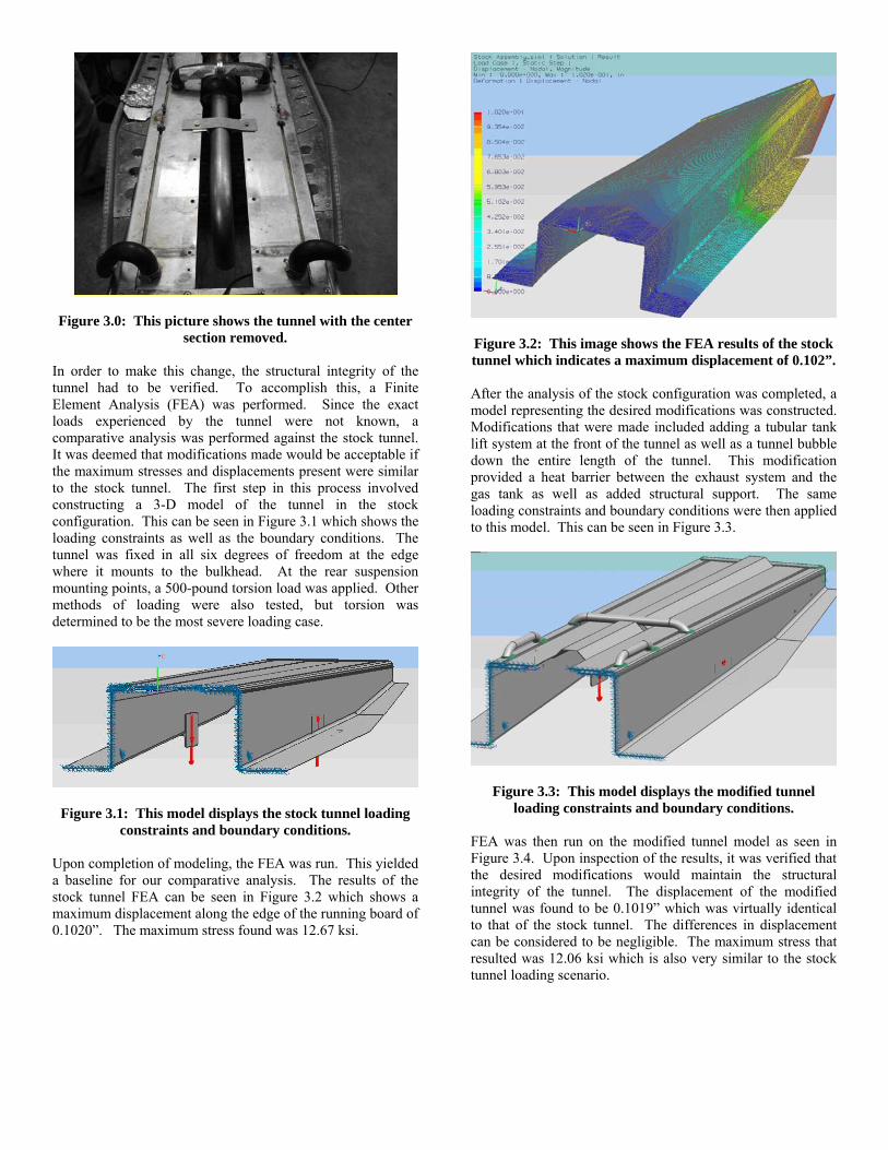
Figure 3.0: This picture shows the tunnel with the center
section removed. In order to make this change, the structural integrity of the tunnel had to be verified. To accomplish this, a Finite Element Analysis (FEA) was performed. Since the exact loads experienced by the tunnel were not known, a comparative analysis was performed against the stock tunnel. It was deemed that modifications made would be acceptable if the maximum stresses and displacements present were similar to the stock tunnel. The first step in this process involved constructing a 3-D model of the tunnel in the stock configuration. This can be seen in Figure 3.1 which shows the loading constraints as well as the boundary conditions. The tunnel was fixed in all six degrees of freedom at the edge where it mounts to the bulkhead. At the rear suspension mounting points, a 500-pound torsion load was applied. Other methods of loading were also tested, but torsion was determined to be the most severe loading case.
Figure 3.1: This model displays the stock tunnel loading constraints and boundary conditions.
Upon completion of modeling, the FEA was run. This yielded a baseline for our comparative analysis. The results of the stock tunnel FEA can be seen in Figure 3.2 which shows a maximum displacement along the edge of the running board of 0.1020”. The maximum stress found was 12.67 ksi.
Figure 3.2: This image shows the FEA results of the stock tunnel which indicates a maximum displacement of 0.102”. After the analysis of the stock configuration was completed, a model representing the desired modifications was constructed. Modifications that were made included adding a tubular tank lift system at the front of the tunnel as well as a tunnel bubble down the entire length of the tunnel. This modification provided a heat barrier between the exhaust system and the gas tank as well as added structural support. The same loading constraints and boundary conditions were then applied to this model. This can be seen in Figure 3.3.
Figure 3.3: This model displays the modified tunnel loading constraints and boundary conditions.
FEA was then run on the modified tunnel model as seen in Figure 3.4. Upon inspection of the results, it was verified that the desired modifications would maintain the structural integrity of the tunnel. The displacement of the modified tunnel was found to be 0.1019” which was virtually identical to that of the stock tunnel. The differences in displacement can be considered to be negligible. The maximum stress that resulted was 12.06 ksi which is also very similar to the stock tunnel loading scenario.

Figure 3.4: This image shows the FEA results of the modified tunnel which indicates a maximum displacement
of 0.1019”. Rear Suspension In 2008 an Arctic Cat Firecat rear suspension was utilized due to the narrow nature of the skid. Being 1.5” narrower than a stock Polaris skid allowed for the use of rubber isolation mounts which decreased vibrations transferred from the suspension to the chassis. While this selection worked relatively well in the past for the team, it was not the lightest or best handling suspension on the market. In total, the four isolation mounts added up to four pounds. To meet the 2009 goal to reduce the weight of the snowmobile by 7%, a lighter option had to be explored. The 2009 Ski-Doo SC-5 suspension was found to be the best option. In order to implement this suspension, the front and rear torque arms had to be narrowed since the Ski-Doo tunnel is 1” wider than the Polaris tunnel. The rear torque arm was simply modified by machining 1/2” off each side. The front torque arm had to have 5/8” machined off each side to allow for a 1/8” structural plate to be welded on each side. This was necessary in order to maintain structural integrity of the torque arm since part of the tubing was removed during machining. This can be seen in Figure 4.0.
Figure 4.0: This picture displays the modifications made
to the front torque arm of the SC-5 rear suspension. While the 128” Firecat skid weighs 55 pounds, the 120” SC-5 suspension weighs only 45 pounds. This weight savings was
critical in making sure the snowmobile was much lighter and more competitive. Front A-Arms The stock Polaris front suspension consists of two unequal length, non-parallel A-arms with a coil-over shock mounted to the lower control arm on each side. This can be seen in a 3-D model in Figure 5.0. In a further effort to reduce the overall weight of the 2008 competition snowmobile the front suspension was redesigned using aluminum instead of steel. Although the FEA of the 2008 A-arms verified the design would not fail, field testing proved otherwise. On snow testing revealed a higher than expected load on the lower A-arms at the sway bar mount. This load was sufficient enough to surpass the yield point of the aluminum and resulted in failure. Though the lower A-arms failed, the upper A-arm design was proven through validation testing.
Figure 5.0: This image displays a 3-D cad model of the Polaris FST front suspension.
For 2009 the upper A-arm design has been left unchanged, while the lower A-arms have undergone slight modifications. In order to increase the rigidity of the lower A-arms, the material thicknesses used has been increased and an additional cross support has been added. FEA was used in order to verify design changes before rebuilding the a-arms. Material thicknesses were increased in increments based on what was commercially available until deflection in the modified arm was less than 70% from the 2008 design under similar loading conditions. The results of a front impact on the lower a-arm can be seen in Figure 5.1.
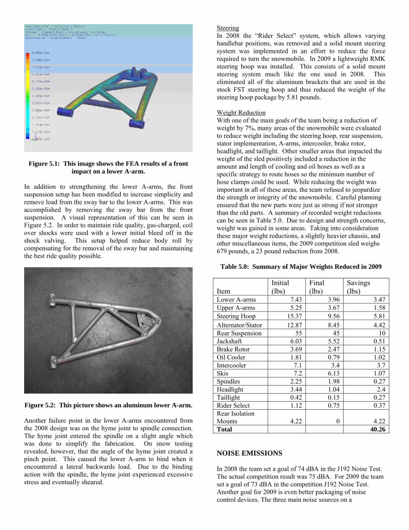
Figure 5.1: This image shows the FEA results of a front impact on a lower A-arm.
In addition to strengthening the lower A-arms, the front suspension setup has been modified to increase simplicity and remove load from the sway bar to the lower A-arms. This was accomplished by removing the sway bar from the front suspension. A visual representation of this can be seen in Figure 5.2. In order to maintain ride quality, gas-charged, coil over shocks were used with a lower initial bleed off in the shock valving. This setup helped reduce body roll by compensating for the removal of the sway bar and maintaining the best ride quality possible.
Figure 5.2: This picture shows an aluminum lower A-arm. Another failure point in the lower A-arms encountered from the 2008 design was on the hyme joint to spindle connection. The hyme joint entered the spindle on a slight angle which was done to simplify the fabrication. On snow testing revealed, however, that the angle of the hyme joint created a pinch point. This caused the lower A-arm to bind when it encountered a lateral backwards load. Due to the binding action with the spindle, the hyme joint experienced excessive stress and eventually sheared.
Steering In 2008 the “Rider Select” system, which allows varying handlebar positions, was removed and a solid mount steering system was implemented in an effort to reduce the force required to turn the snowmobile. In 2009 a lightweight RMK steering hoop was installed. This consists of a solid mount steering system much like the one used in 2008. This eliminated all of the aluminum brackets that are used in the stock FST steering hoop and thus reduced the weight of the steering hoop package by 5.81 pounds. Weight Reduction With one of the main goals of the team being a reduction of weight by 7%, many areas of the snowmobile were evaluated to reduce weight including the steering hoop, rear suspension, stator implementation, A-arms, intercooler, brake rotor, headlight, and taillight. Other smaller areas that impacted the weight of the sled positively included a reduction in the amount and length of cooling and oil hoses as well as a specific strategy to route hoses so the minimum number of hose clamps could be used. While reducing the weight was important in all of these areas, the team refused to jeopardize the strength or integrity of the snowmobile. Careful planning ensured that the new parts were just as strong if not stronger than the old parts. A summary of recorded weight reductions can be seen in Table 5.0. Due to design and strength concerns, weight was gained in some areas. Taking into consideration these major weight reductions, a slightly heavier chassis, and other miscellaneous items, the 2009 competition sled weighs 679 pounds, a 23 pound reduction from 2008.
Table 5.0: Summary of Major Weights Reduced in 2009
Item Initial (lbs)
Final (lbs)
Savings (lbs)
Lower A-arms 7.43 3.96 3.47 Upper A-arms 5.25 3.67 1.58 Steering Hoop 15.37 9.56 5.81 Alternator/Stator 12.87 8.45 4.42 Rear Suspension 55 45 10 Jackshaft 6.03 5.52 0.51 Brake Rotor 3.69 2.47 1.15 Oil Cooler 1.81 0.79 1.02 Intercooler 7.1 3.4 3.7 Skis 7.2 6.13 1.07 Spindles 2.25 1.98 0.27 Headlight 3.44 1.04 2.4 Taillight 0.42 0.15 0.27 Rider Select 1.12 0.75 0.37 Rear Isolation Mounts 4.22 0 4.22 Total 40.26
NOISE EMISSIONS In 2008 the team set a goal of 74 dBA in the J192 Noise Test. The actual competition result was 75 dBA. For 2009 the team set a goal of 73 dBA in the competition J192 Noise Test. Another goal for 2009 is even better packaging of noise control devices. The three main noise sources on a

snowmobile are the engine exhaust, engine intake, and the track and rear suspension. By analyzing each source and treating each component separately in a coherent noise reduction strategy, the team felt that the highest level of success would be achieved. Noise dampening material was added to the 2008 air box to help reduce the intake noise emissions. Soundown acoustical absorption and barrier material was added under the hood to help reduce the noise produced by the engine and valve train systems. Exhaust Noise Reduction Due to the layout of the rear exit exhaust system, the muffler is located behind the seat on the rear of the snowmobile. Since packaging is a concern, the team chose to use an expansion chamber style muffler consisting of dual baffles. This style muffler consists of three varying size chambers to target low frequencies produced by the engine. The chambers measure 10”, 4”, and 6” in length respectively. Due to the importance of the relationship between the inlet tube diameter and the muffler volume, an 8” diameter muffler was used since the overall length was constrained by the length of the chassis. The separate chambers can be seen in Figure 6.0 which shows the muffler after final assembly.
Figure 6.0: This picture shows the MTU designed and fabricated muffler after final assembly.
Before construction of the muffler took place, Catia V5 was used to construct a 3-D model of the muffler so that boundary element analysis could be conducted using LMS Virtual Lab. This ensured that our design would be effective in eliminating target frequencies. A list of target frequencies was generated based on testing and experience for a two-cylinder four- stroke engine. Figure 6.1 shows the 3-D model that was used in the initial analysis. This design did not include an extended inlet or outlet.
Figure 6.1: This 3-D model displays the muffler without extended inlet or outlet tubes.
Using Matlab simulations based on acoustic impedance modeling, a transmission loss curve was generated for the model. This can be seen in Figure 6.2. The dips in the transmission loss curve were identified as frequencies which were targeted for improvement with the extended inlet and outlet design.
Figure 6.2: This graph is a software generated
transmission loss curve of the muffler without extended inlet or outlet tubes.
After the initial analysis was completed, the results were entered into a Matlab program to calculate the proper lengths for the extended inlet and outlet tubes for optimum noise cancellation. The inlet tube was found to be 4.4” while the outlet tube was 2” in length. Perforated tubing with solid end caps were used for the extended inlet and outlet tubes to increase sound wave dispersion. An example of this can be seen in Figure 6.3.

Figure 6.3: This picture shows the end chamber of the muffler which contains perforated tubing with an end cap.
A 3-D model was then generated to accurately reflect these findings. This can be seen in Figure 6.4.
Figure 6.4: This 3-D model displays the muffler with extended inlet and outlet tubes.
Upon finalizing the 2nd generation design, a new muffler was constructed. This muffler was again bench tested to estimate its transmission loss characteristics. These results are shown in Figure 6.5. It can clearly be seen that the addition of the extended inlet and outlet improved the performance at frequencies where there were dips in the original design. The higher frequency dips were eliminated by the Silco Soft packing used in the muffler.
Figure 6.5: This graph is a software generated transmission loss curve of the completed MTU muffler
which uses data obtained by physical testing.
DRIVE TRAIN Many of the drive train components in the 2008 snowmobile were replaced from stock in an effort to reduce weight and increase efficiency. This effort was built upon in 2009 with the goals of reducing more weight and still increasing efficiency over 2008. In 2008, the driveshaft, jackshaft, chain case, and brake rotor were the main points of focus. The stock jackshaft was replaced with a shorter 2008 Polaris Dragon IQ jackshaft to fit the replacement chain case. The new chain case installed was also a 2008 Dragon IQ component. It eliminated the reverse mechanism and complicated chain case cover, which lead to more packaging options for the air intake system. In 2009, the brake rotor and driveshaft were the main focus areas while all other changes from 2008 remained intact. The team investigated many options for reducing the rotational inertia within the drive train. In 2008, the stock brake rotor was modified to reduce the weight as well as improve cooling. This rotor was slotted reducing the surface area by 14.9%. Taking into consideration rule 4.4.3 which states that the surface area of a brake rotor can be reduced by a maximum of 15%, the team needed to come up with a new strategy for reducing the weight of the brake rotor. [3] In 2009 Polaris used a lightweight brake rotor on the Polaris Dragon IQ. This rotor was 9.92 ounces lighter than the already modified rotor from 2008. This was accomplished by installing a WAVE style rotor which is known to be an industry leading lightweight rotor. Taking this into consideration, it was decided to use this particular rotor and can be seen in Figure 7.0.
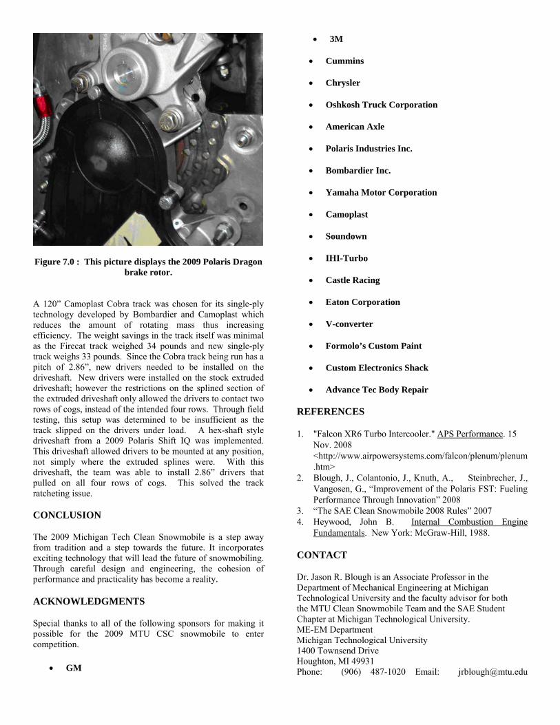
Figure 7.0 : This picture displays the 2009 Polaris Dragon brake rotor.
A 120” Camoplast Cobra track was chosen for its single-ply technology developed by Bombardier and Camoplast which reduces the amount of rotating mass thus increasing efficiency. The weight savings in the track itself was minimal as the Firecat track weighed 34 pounds and new single-ply track weighs 33 pounds. Since the Cobra track being run has a pitch of 2.86”, new drivers needed to be installed on the driveshaft. New drivers were installed on the stock extruded driveshaft; however the restrictions on the splined section of the extruded driveshaft only allowed the drivers to contact two rows of cogs, instead of the intended four rows. Through field testing, this setup was determined to be insufficient as the track slipped on the drivers under load. A hex-shaft style driveshaft from a 2009 Polaris Shift IQ was implemented. This driveshaft allowed drivers to be mounted at any position, not simply where the extruded splines were. With this driveshaft, the team was able to install 2.86” drivers that pulled on all four rows of cogs. This solved the track ratcheting issue. CONCLUSION
The 2009 Michigan Tech Clean Snowmobile is a step away from tradition and a step towards the future. It incorporates exciting technology that will lead the future of snowmobiling. Through careful design and engineering, the cohesion of performance and practicality has become a reality.
ACKNOWLEDGMENTS
Special thanks to all of the following sponsors for making it possible for the 2009 MTU CSC snowmobile to enter competition.
• GM
• 3M
• Cummins
• Chrysler
• Oshkosh Truck Corporation
• American Axle
• Polaris Industries Inc.
• Bombardier Inc.
• Yamaha Motor Corporation
• Camoplast
• Soundown
• IHI-Turbo
• Castle Racing
• Eaton Corporation
• V-converter
• Formolo’s Custom Paint
• Custom Electronics Shack
• Advance Tec Body Repair
REFERENCES
1. "Falcon XR6 Turbo Intercooler." APS Performance. 15 Nov. 2008 <http://www.airpowersystems.com/falcon/plenum/plenum.htm>
2. Blough, J., Colantonio, J., Knuth, A., Steinbrecher, J., Vangosen, G., “Improvement of the Polaris FST: Fueling Performance Through Innovation” 2008
3. “The SAE Clean Snowmobile 2008 Rules” 2007 4. Heywood, John B. Internal Combustion Engine
Fundamentals. New York: McGraw-Hill, 1988. CONTACT
Dr. Jason R. Blough is an Associate Professor in the Department of Mechanical Engineering at Michigan Technological University and the faculty advisor for both the MTU Clean Snowmobile Team and the SAE Student Chapter at Michigan Technological University. ME-EM Department Michigan Technological University 1400 Townsend Drive Houghton, MI 49931 Phone: (906) 487-1020 Email: [email protected]