Embed Size (px)
Citation preview
ORIGINAL PAPER
Improvement of the first coulomb efficiency and rateperformance of Li1.5Ni0.25Mn0.75O2.5 with spinelLiNi0.5Mn1.5O4 doping
Yunjian Liu & Jun Lv & Guangyan Zhu & Yanyong Gao &
Sanbin Liu & Xiaohua Chen
Received: 20 December 2012 /Revised: 10 January 2013 /Accepted: 20 January 2013# Springer-Verlag Berlin Heidelberg 2013
Abstract Li1.1Ni0.25Mn0.75O2.3 and Li1.5Ni0.25Mn0.75O2.5
have been synthesized by co-precipitation method. The effectof the LiNi0.5Mn1.5O4 spinel structure on physical and electro-chemical properties is discussed through the characterizationsof X-ray diffraction (XRD), scanning electron microscopy,high-resolution transmission electron microscopy, cyclic vol-tammetry (CV), electrochemical impedance spectroscopy(EIS), and electrochemical performance tests. TheLiNi0.5Mn1.5O4 spinel structure is detected in the XRD pattern,TEM image, first discharge, and CV curves of theLi1.1Ni0.25Mn0.75O2.3 electrode. The rate, cyclic performance,and first coulomb efficiency of Li1.1Ni0.25Mn0.75O2.35 arehigher than those of Li1.5Ni0.25Mn0.75O2.5. The first coulombefficiencies of Li1.1Ni0.25Mn0.75O2.3 and Li1.5Ni0.25Mn0.75O2.5
are 86.2 and 74.7 %, and the capacity retentions are 98.7 and94.1 % after 50 cycles, respectively. EIS results indicate thatthe charge-transfer reaction resistance of Li1.1Ni0.25Mn0.75O2.3
is lower than that of Li1.5Ni0.25Mn0.75O2.5, which is responsi-ble for the better rate capacity of Li1.1Ni0.25Mn0.75O2.3.
Keywords Layered manganese-enriched electrode .
LiNi0.5Mn1.5O4. Doping . Electrochemical performance .
Electrochemical impedance spectroscopy
Introduction
Recently, lithium- and manganese-enriched oxides have re-ceived much attention [1–5]. These materials have an
overall lithium-to-transition metal stoichiometry greaterthan 1.0 and have greater than half of the relative transitionmetal composition, which is manganese. These materials arecomposites of layered LiMO2 (R3m) and Li2MnO3 (C2/m)structures [4, 5]. The Li2MnO3 component that suppliessurplus lithium to the layered structure plays a critical rolein stabilizing the electrode structure at low lithium loadings[4]; on lithium extraction, lithium ions in the transition metallayers diffuse into the lithium-depleted layers to providesufficient binding energy to maintain the integrity of theclose-packed oxygen array [6, 7].
During the initial charge, electrochemical extraction oflithium from xLi2MnO3•(1−x)LiMO2 electrodes occurs intwo steps [8]. When taken to completion above 4.6 V vs.Li0, the ideal reactions can be represented as follows:
LiMO2 ! MnO2 þ Liþ þ e�; ð1Þ
Li2MnO3 ! MnO2 þ 2Liþ þ 1
2O2 þ 2e�: ð2Þ
An investigation of the solid solution system has shownthat the irreversible capacity values of these materials can beas large as 40–100 mAhg−1 on charging to 4.8 V, dependingon the composition [6]. In addition, its poor rate perfor-mance should be improved to satisfy the desire for plug-inhybrid vehicle (PHEV) applications as well as for portableelectronic equipment and power tools. Surface coatings suchas Li–Ni–PO4 [9], carbon [10], Al2O3, CeO2, ZrO2, ZnO,AlPO4, or AlF3 [11–13] have been reported to improve thefirst coulomb efficiency and rate capability of lithium-andmanganese-enriched oxides. However, the improvement isdissatisfactory for PHEVapplications as well as for portableelectronic equipment and power tools. Furthermore, thesurface coating is a complicated technology and is notsuitable for practical production. Thus, it is necessary andimportant to find another method to improve the first
Y. Liu (*) : J. Lv :Y. GaoSchool of Material Science and Technology, Jiangsu University,Zhenjiang, Chinae-mail: [email protected]
Y. Liu :G. Zhu : S. Liu :X. ChenPostdoctoral Workstation of Chery Automobile Co., Ltd, Wuhu,Anhui, China
IonicsDOI 10.1007/s11581-013-0859-4
coulomb efficiency and rate performance of lithium- andmanganese-enriched oxides.
The spinel LiNi0.5Mn1.5O4 is another promising cathodematerial for PHEV applications because of its excellent rateperformance [14, 15]; hollow structures of LiNi0.5Mn1.5O4
have been shown to exhibit a good rate property [15]. Therate performance of spinel structure is excellent, which isexpected to improve the rate performance of lithium- andmanganese-enriched oxide materials. Amine et al. [16] andThackeray et al. [17] have reported that it is also possible tohave a spinel phase (Fd3m) embedded within the lithium- andmanganese-enriched oxide materials. However, compositelayered and spinel materials have been synthesized by solid-state reaction using LiOH•H2O and Mn(OH)2 or Ni(NO3)2•6H2O,Mn(NO3)2•4H2O, and LiNO3 in the mentionedpaper, and the discharge capacities of Li1+xNi0.5Mn1.5O2.25+x/2
(x=0.25, x=0.375) are low. Furthermore, the improvement ofthe first coulomb efficiency and rate performance has not beenreported in the papers of Thackeray and Amine.
In this paper, the Li1.1Ni0.25Mn0.75O2.3 (calculated as 0.6Li1.5Ni0.25Mn0.75O2.5•0.2 LiNi0.5Mn1.5O4), which containsthe LiNi0.5Mn1.5O4 phase, has been synthesized by co-precipitation method. The effects of the LiNi0.5Mn1.5O4 struc-ture on the structure, image, initial discharge capacity, inter-facial impedance, electrochemical performance, especiallyrate performance, and first coulomb efficiency have beenstudied to be compared with those of Li1.5Ni0.25Mn0.75O2.5.
Experimental
The layered Li1.1Ni0.25Mn0.75O2.3 and Li1.5Ni0.25Mn0.75O2.5
oxide solid solutions were all synthesized by co-precipitationmethod as described here. Required amounts of transitionmetal acetates were dissolved in distilled water and then addeddrop by drop into a 0.1-M NaOH solution to form the co-precipitated hydroxides of Mn and Ni, which were then driedovernight at 100 °C in an air oven, mixed with a requiredamount of lithium carbonate, heated in air at 500 °C for 4 hand 900 °C for 12 h, and then quenched in liquid nitrogen.
The crystal structure of the as-prepared powders was char-acterized by X-ray diffraction (XRD; Rigaku D/max-γB) withmonochromated CuKα radiation (45 kV, 50 mA) between 10°and 80° with a step size of 0.02°. The particle size andmorphology of the samples were examined by scanning elec-tron microscopy (SEM; FEI, Quanta200F) and transmissionelectron microscopy (TEM; Hitachi, 7650).
Electrochemical measurements were carried out usingR2025 coin-type cells. The positive electrodes were pre-pared by coating a mixture containing 80 % active materials,10 % acetylene black, 10 % poly(vinylidene fluoride) binderon circular Al current collector foils, followed by drying at120 °C for 1 h. Electrochemical cells were assembled with
the positive electrodes as prepared, with metallic lithium foilas counter electrode, Celgard 2400 as separator, and 1 MLiPF6 dissolved in ethyl carbonate and dimethyl carbonate(1:1 in volume) as electrolyte in an argon-filled glove box.First charge–discharge experiments were performed with0.1 C between 2.0 and 4.8 V on battery testers (LandCT2001A). The cyclic performances of synthesized sampleswere tested with 0.2 C.
The cyclic voltammetry (CV) and electrochemical im-pedance spectroscopy (EIS) of the cell were measuredusing CHI660A (Chenghua Instrument Co. Ltd, Shanghai)with three electrodes. The amplitude of the AC signal was5 mV over the frequency between 100 kHz and 0.01 Hz.The sweep rate of CV was 0.1 mVs−1 over a potential of2.0–5.0 V.
Results and discussion
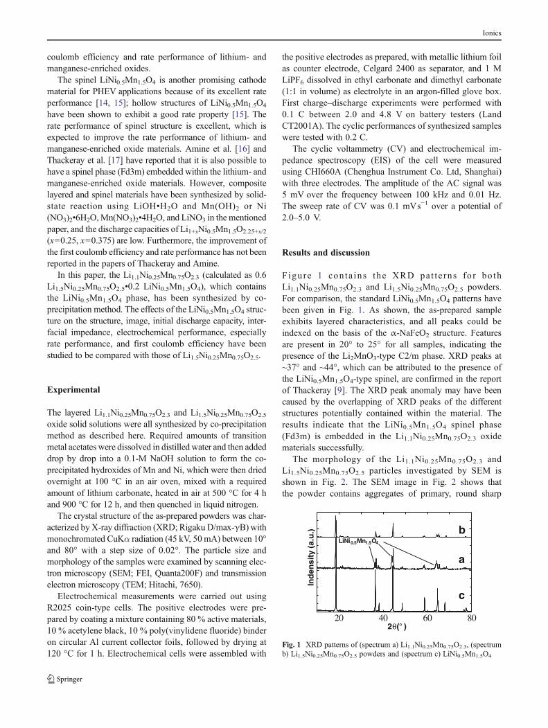
Figu re 1 con ta ins the XRD pa t t e rns fo r bo thLi1.1Ni0.25Mn0.75O2.3 and Li1.5Ni0.25Mn0.75O2.5 powders.For comparison, the standard LiNi0.5Mn1.5O4 patterns havebeen given in Fig. 1. As shown, the as-prepared sampleexhibits layered characteristics, and all peaks could beindexed on the basis of the α-NaFeO2 structure. Featuresare present in 20° to 25° for all samples, indicating thepresence of the Li2MnO3-type C2/m phase. XRD peaks at~37° and ~44°, which can be attributed to the presence ofthe LiNi0.5Mn1.5O4-type spinel, are confirmed in the reportof Thackeray [9]. The XRD peak anomaly may have beencaused by the overlapping of XRD peaks of the differentstructures potentially contained within the material. Theresults indicate that the LiNi0.5Mn1.5O4 spinel phase(Fd3m) is embedded in the Li1.1Ni0.25Mn0.75O2.3 oxidematerials successfully.
The morphology of the Li1.1Ni0.25Mn0.75O2.3 andLi1.5Ni0.25Mn0.75O2.5 particles investigated by SEM isshown in Fig. 2. The SEM image in Fig. 2 shows thatthe powder contains aggregates of primary, round sharp
20 40 60 80
a
b
2θ(° )
Ind
ensi
ty (
a.u
.)
LiNi0.5Mn1.5O4
c
Fig. 1 XRD patterns of (spectrum a) Li1.1Ni0.25Mn0.75O2.3, (spectrumb) Li1.5Ni0.25Mn0.75O2.5 powders and (spectrum c) LiNi0.5Mn1.5O4
Ionics
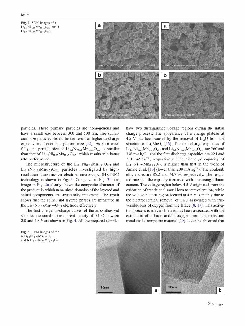
particles. These primary particles are homogenous andhave a small size between 300 and 500 nm. The submi-cron size particles should be the result of higher dischargecapacity and better rate performance [18]. As seen care-fully, the particle size of Li1.1Ni0.25Mn0.75O2.3 is smallerthan that of Li1.5Ni0.25Mn0.75O2.5, which results in a betterrate performance.
The microstructure of the Li1.1Ni0.25Mn0.75O2.3 andLi1.5Ni0.25Mn0.75O2.5 particles investigated by high-resolution transmission electron microscopy (HRTEM)technology is shown in Fig. 3. Compared to Fig. 3b, theimage in Fig. 3a clearly shows the composite character ofthe product in which nano-sized domains of the layered andspinel components are structurally integrated. The resultshows that the spinel and layered phases are integrated inthe Li1.1Ni0.25Mn0.75O2.3 electrode effectively.
The first charge–discharge curves of the as-synthesizedsamples measured at the current density of 0.1 C between2.0 and 4.8 V are shown in Fig. 4. All the prepared samples
have two distinguished voltage regions during the initialcharge process. The appearance of a charge plateau at4.5 V has been caused by the removal of Li2O from thestructure of Li2MnO3 [16]. The first charge capacities ofLi1.1Ni0.25Mn0.75O2.3 and Li1.5Ni0.25Mn0.75O2.5 are 260 and336 mAhg−1, and the first discharge capacities are 224 and251 mAhg−1, respectively. The discharge capacity ofLi1.1Ni0.25Mn0.75O2.3 is higher than that in the work ofAmine et al. [16] (lower than 200 mAhg−1). The coulombefficiencies are 86.2 and 74.7 %, respectively. The resultsindicate that the capacity increased with increasing lithiumcontent. The voltage region below 4.5 Voriginated from theoxidation of transitional metal ions to tetravalent ion, whilethe voltage plateau region located at 4.5 V is mainly due tothe electrochemical removal of Li2O associated with irre-versible loss of oxygen from the lattice [8, 17]. This activa-tion process is irreversible and has been associated with theextraction of lithium and/or oxygen from the transitionmetal oxide composite material [19]. It can be observed that
a a
b b
Fig. 2 SEM images of aLi1.1Ni0.25Mn0.75O2.3 and bLi1.5Ni0.25Mn0.75O2.5
a b10nm 10nm
Fig. 3 TEM images of thea Li1.1Ni0.25Mn0.75O2.3
and b Li1.5Ni0.25Mn0.75O2.5
Ionics

the voltage curve of each sample varies with compositionchange, in particular, with the Li2MnO3 value. As theamount of Li2MnO3 increases, the charge voltage curvefor the voltage region (below 4.5 V) starts to shift to ahigher voltage while the voltage plateau (at 4.5 V) becomeslonger. In addition, the total initial charge and dischargecapacities increase as the amount of Li2MnO3 increases.Besides, the coulomb efficiency increased with decreasinglithium content. To our knowledge, the irreversible capac-ity loss is due to the extraction of lithium as “Li2O” oncharging from the Li2MnO3. The content of Li2MnO3 inthe Li1.1Ni0.25Mn0.75O2.3 is lower than that in theLi1.5Ni0.25Mn0.75O2.5, which will result in lower irreversiblecapacity loss and higher coulomb efficiency. To our knowl-edge, the discharge capacity under 3 V of LiNi0.5Mn1.5O4
should be another reason for higher first coulomb efficiencyof Li1.1Ni0.25Mn0.75O2.3.
As shown in Fig. 4, there two other plateaus at about 4.7and 2.8 V in the discharge curves of Li1.1Ni0.25Mn0.75O2.3.To our knowledge, the 4.7 V plateau originates from theNi2+/Ni4+ redox couple and the ordering of lithium at 8asites with 50 % filling in the LiNi0.5Mn1.5O4 phase [20]. Thereaction plateau at 2.8 V is associated with the reversible, first-order spinel Li[Ni0.5Mn1.5]O4 to rock salt Li2[Ni0.5Mn1.5]O4
transformation during which lithium ions are displaced fromthe tetrahedral to the octahedral site with concomitant reduc-tion of the tetravalent manganese ions to an average oxidationstate of 3.33 [21].
Figure 5 shows the CV of Li1.1Ni0.25Mn0.75O2.3 andLi1.5Ni0.25Mn0.75O2.5 cathode electrodes measured with thepotential between 2.0 and 5.0 V at a sweep rate of 0.1 mVs−1 at room temperature. As seen in Fig. 5, the redox peaksat about 3.3 and 3.9 V, which correspond to the lithiuminsertion/extraction reaction from the octahedral site [22],are detected in the curves of Li1.1Ni0.25Mn0.75O2.3 andLi1.5Ni0.25Mn0.75O2.5 cathode electrodes. However, two
other redox peaks at about 3.0 and 4.7 Vare found in the curveof the Li1.1Ni0.25Mn0.75O2.3 electrode. The redox peaks atabout 3.0 V is associated with the reversible, first-order spinelLiNi0.5Mn1.5O4 to rock salt Li2Ni0.5Mn1.5O4 transformationduring which lithium ions are displaced from the tetrahedralto the octahedral site with concomitant reduction of the tetra-valent manganese ions to an average oxidation state of 3.33[21]. The peaks at about 4.7 V correspond to the Ni2+/Ni4+
redox couple in the LiNi0.5Mn1.5O4 phase [23]. The resultsconfirm the existence of the LiNi0.5Mn1.5O4 phase inLi1.1Ni0.25Mn0.75O2.3 and are in agreement with the dischargecurve of Li1.1Ni0.25Mn0.75O2.3.
Discharge capacity (0.2 C) versus cycle number plotsfor the 50 cycles of the various lithium cells whencycled between 4.8 and 2 V are shown in Fig. 6. After50 cycles, the capacities of Li1.1Ni0.25Mn0.75O2.3 andLi1.5Ni0.25Mn0.75O2.5 are 208 and 210 mAhg−1, respec-tively, which are 98.7 and 94.1 % of their initial dis-charge capacities of 0.2 C. The results show that thecycling performance of Li1.1Ni0.25Mn0.75O2.3 is betterthan that of Li1.5Ni0.25Mn0.75O2.5, which indicates thatthe LiNi0.5Mn1.5O4 spinel phase is good to the cyclicperformance of lithium- and manganese-enriched oxides.
0 50 100 150 200 250 300 350 400
2.0
2.5
3.0
3.5
4.0
4.5
5.0V
olat
ge (
V)
Capacity (mAh/g)
x=0.1 x=0.5
Fig. 4 First charge and discharge curves Li1+xNi0.25Mn0.75Mn2.25+x/2
2 3 4 5
-0.0001
0
0.0001
0.0002
x=0.1
x=0.5
Cur
rent
(A
)
Voltage (V)
Fig. 5 Cyclic voltammetry curves of Li1+xNi0.25Mn0.75O2.25+x/2 cath-ode electrodes
0 10 20 30 40 50180
200
220
240
x=0.1 x=0.5
Cap
acity
(m
Ah/
g)
Cycle Numbers
Fig. 6 Cyclic performance of Li1+xNi0.25Mn0.75O2.25+x/2
Ionics
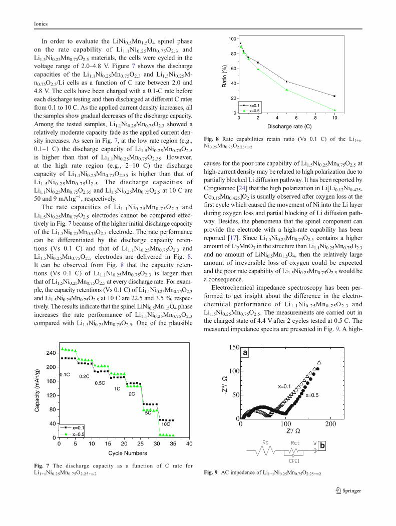
In order to evaluate the LiNi0.5Mn1.5O4 spinel phaseon the rate capability of Li1.1Ni0.25Mn0.75O2.3 andLi1.5Ni0.25Mn0.75O2.5 materials, the cells were cycled in thevoltage range of 2.0–4.8 V. Figure 7 shows the dischargecapacities of the Li1.1Ni0.25Mn0.75O2.3 and Li1.5Ni0.25M-n0.75O2.5/Li cells as a function of C rate between 2.0 and4.8 V. The cells have been charged with a 0.1-C rate beforeeach discharge testing and then discharged at different C ratesfrom 0.1 to 10 C. As the applied current density increases, allthe samples show gradual decreases of the discharge capacity.Among the tested samples, Li1.1Ni0.25Mn0.75O2.3 showed arelatively moderate capacity fade as the applied current den-sity increases. As seen in Fig. 7, at the low rate region (e.g.,0.1–1 C) the discharge capacity of Li1.5Ni0.25Mn0.75O2.5
is higher than that of Li1.1Ni0.25Mn0.75O2.35. However,at the high rate region (e.g., 2–10 C) the dischargecapacity of Li1.1Ni0.25Mn0.75O2.35 is higher than that ofLi1.5Ni0.25Mn0.75O2.5. The discharge capacities ofLi1.1Ni0.25Mn0.75O2.35 and Li1.5Ni0.25Mn0.75O2.5 at 10 C are50 and 9 mAhg−1, respectively.
The rate capacities of Li1.1Ni0.25Mn0.75O2.3 andLi1.5Ni0.25Mn0.75O2.5 electrodes cannot be compared effec-tively in Fig. 7 because of the higher initial discharge capacityof the Li1.5Ni0.25Mn0.75O2.5 electrode. The rate performancecan be differentiated by the discharge capacity reten-tions (Vs 0.1 C) and that of Li1.1Ni0.25Mn0.75O2.3 andLi1.5Ni0.25Mn0.75O2.5 electrodes are delivered in Fig. 8.It can be observed from Fig. 8 that the capacity reten-tions (Vs 0.1 C) of Li1.1Ni0.25Mn0.75O2.3 is larger thanthat of Li1.5Ni0.25Mn0.75O2.5 at every discharge rate. For exam-ple, the capacity retentions (Vs 0.1 C) of Li1.1Ni0.25Mn0.75O2.3
and Li1.5Ni0.25Mn0.75O2.5 at 10 C are 22.5 and 3.5 %, respec-tively. The results indicate that the spinel LiNi0.5Mn1.5O4 phaseincreases the rate performance of Li1.1Ni0.25Mn0.75O2.3
compared with Li1.5Ni0.25Mn0.75O2.5. One of the plausible
causes for the poor rate capability of Li1.5Ni0.25Mn0.75O2.5 athigh-current density may be related to high polarization due topartially blocked Li diffusion pathway. It has been reported byCroguennec [24] that the high polarization in Li[Li0.12Ni0.425-Co0.15Mn0.425]O2 is usually observed after oxygen loss at thefirst cycle which caused the movement of Ni into the Li layerduring oxygen loss and partial blocking of Li diffusion path-way. Besides, the phenomena that the spinel component canprovide the electrode with a high-rate capability has beenreported [17]. Since Li1.5Ni0.25Mn0.75O2.5 contains a higheramount of Li2MnO3 in the structure than Li1.1Ni0.25Mn0.75O2.3
and no amount of LiNi0.5Mn1.5O4, then the relatively largeamount of irreversible loss of oxygen could be expectedand the poor rate capability of Li1.5Ni0.25Mn0.75O2.5 would bea consequence.
Electrochemical impedance spectroscopy has been per-formed to get insight about the difference in the electro-chemical performance of Li1.1Ni0.25Mn0.75O2.3 andLi1.5Ni0.25Mn0.75O2.5. The measurements are carried out inthe charged state of 4.4 V after 2 cycles tested at 0.5 C. Themeasured impedance spectra are presented in Fig. 9. A high-
0 5 10 15 20 25 30 35 400
40
80
120
160
200
240
Cap
acity
(m
Ah/
g)
Cycle Numbers
x=0.1 x=0.5
0.1C 0.2C0.5C
1C2C
5C
10C
Fig. 7 The discharge capacity as a function of C rate forLi1+xNi0.25Mn0.75O2.25+x/2
0 2 4 6 8 100
20
40
60
80
100
Rat
io (
%)
Discharge rate (C)
x=0.1 x=0.5
Fig. 8 Rate capabilities retain ratio (Vs 0.1 C) of the Li1+x-Ni0.25Mn0.75O2.25+x/2
0 100 2000
50
100
150
Z'/
-Z''/ x=0.1
x=0.5
b
a
Fig. 9 AC impedence of Li1+xNi0.25Mn0.75O2.25+x/2
Ionics
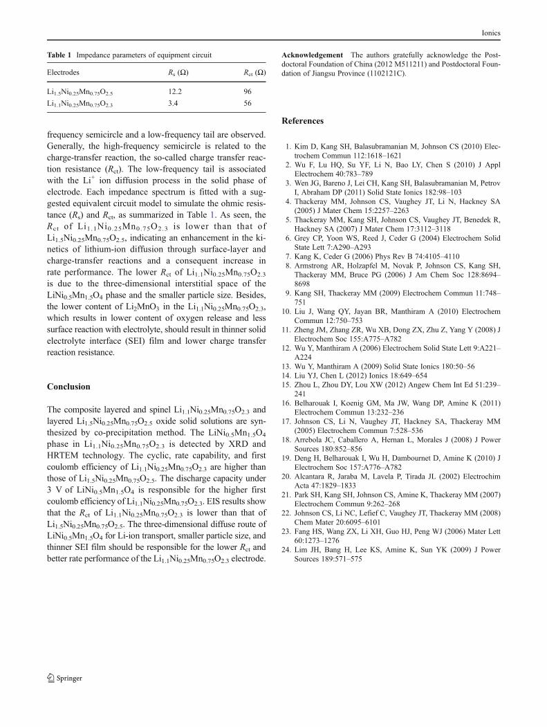
frequency semicircle and a low-frequency tail are observed.Generally, the high-frequency semicircle is related to thecharge-transfer reaction, the so-called charge transfer reac-tion resistance (Rct). The low-frequency tail is associatedwith the Li+ ion diffusion process in the solid phase ofelectrode. Each impedance spectrum is fitted with a sug-gested equivalent circuit model to simulate the ohmic resis-tance (Rs) and Rct, as summarized in Table 1. As seen, theRct of Li1.1Ni0.25Mn0.75O2.3 is lower than that ofLi1.5Ni0.25Mn0.75O2.5, indicating an enhancement in the ki-netics of lithium-ion diffusion through surface-layer andcharge-transfer reactions and a consequent increase inrate performance. The lower Rct of Li1.1Ni0.25Mn0.75O2.3
is due to the three-dimensional interstitial space of theLiNi0.5Mn1.5O4 phase and the smaller particle size. Besides,the lower content of Li2MnO3 in the Li1.1Ni0.25Mn0.75O2.3,which results in lower content of oxygen release and lesssurface reaction with electrolyte, should result in thinner solidelectrolyte interface (SEI) film and lower charge transferreaction resistance.
Conclusion
The composite layered and spinel Li1.1Ni0.25Mn0.75O2.3 andlayered Li1.5Ni0.25Mn0.75O2.5 oxide solid solutions are syn-thesized by co-precipitation method. The LiNi0.5Mn1.5O4
phase in Li1.1Ni0.25Mn0.75O2.3 is detected by XRD andHRTEM technology. The cyclic, rate capability, and firstcoulomb efficiency of Li1.1Ni0.25Mn0.75O2.3 are higher thanthose of Li1.5Ni0.25Mn0.75O2.5. The discharge capacity under3 V of LiNi0.5Mn1.5O4 is responsible for the higher firstcoulomb efficiency of Li1.1Ni0.25Mn0.75O2.3. EIS results showthat the Rct of Li1.1Ni0.25Mn0.75O2.3 is lower than that ofLi1.5Ni0.25Mn0.75O2.5. The three-dimensional diffuse route ofLiNi0.5Mn1.5O4 for Li-ion transport, smaller particle size, andthinner SEI film should be responsible for the lower Rct andbetter rate performance of the Li1.1Ni0.25Mn0.75O2.3 electrode.
Acknowledgement The authors gratefully acknowledge the Post-doctoral Foundation of China (2012 M511211) and Postdoctoral Foun-dation of Jiangsu Province (1102121C).
References
1. Kim D, Kang SH, Balasubramanian M, Johnson CS (2010) Elec-trochem Commun 112:1618–1621
2. Wu F, Lu HQ, Su YF, Li N, Bao LY, Chen S (2010) J ApplElectrochem 40:783–789
3. Wen JG, Bareno J, Lei CH, Kang SH, Balasubramanian M, PetrovI, Abraham DP (2011) Solid State Ionics 182:98–103
4. Thackeray MM, Johnson CS, Vaughey JT, Li N, Hackney SA(2005) J Mater Chem 15:2257–2263
5. Thackeray MM, Kang SH, Johnson CS, Vaughey JT, Benedek R,Hackney SA (2007) J Mater Chem 17:3112–3118
6. Grey CP, Yoon WS, Reed J, Ceder G (2004) Electrochem SolidState Lett 7:A290–A293
7. Kang K, Ceder G (2006) Phys Rev B 74:4105–41108. Armstrong AR, Holzapfel M, Novak P, Johnson CS, Kang SH,
Thackeray MM, Bruce PG (2006) J Am Chem Soc 128:8694–8698
9. Kang SH, Thackeray MM (2009) Electrochem Commun 11:748–751
10. Liu J, Wang QY, Jayan BR, Manthiram A (2010) ElectrochemCommun 12:750–753
11. Zheng JM, Zhang ZR, Wu XB, Dong ZX, Zhu Z, Yang Y (2008) JElectrochem Soc 155:A775–A782
12. Wu Y, Manthiram A (2006) Electrochem Solid State Lett 9:A221–A224
13. Wu Y, Manthiram A (2009) Solid State Ionics 180:50–5614. Liu YJ, Chen L (2012) Ionics 18:649–65415. Zhou L, Zhou DY, Lou XW (2012) Angew Chem Int Ed 51:239–
24116. Belharouak I, Koenig GM, Ma JW, Wang DP, Amine K (2011)
Electrochem Commun 13:232–23617. Johnson CS, Li N, Vaughey JT, Hackney SA, Thackeray MM
(2005) Electrochem Commun 7:528–53618. Arrebola JC, Caballero A, Hernan L, Morales J (2008) J Power
Sources 180:852–85619. Deng H, Belharouak I, Wu H, Dambournet D, Amine K (2010) J
Electrochem Soc 157:A776–A78220. Alcantara R, Jaraba M, Lavela P, Tirada JL (2002) Electrochim
Acta 47:1829–183321. Park SH, Kang SH, Johnson CS, Amine K, Thackeray MM (2007)
Electrochem Commun 9:262–26822. Johnson CS, Li NC, Lefief C, Vaughey JT, Thackeray MM (2008)
Chem Mater 20:6095–610123. Fang HS, Wang ZX, Li XH, Guo HJ, Peng WJ (2006) Mater Lett
60:1273–127624. Lim JH, Bang H, Lee KS, Amine K, Sun YK (2009) J Power
Sources 189:571–575
Table 1 Impedance parameters of equipment circuit
Electrodes Rs (Ω) Rct (Ω)
Li1.5Ni0.25Mn0.75O2.5 12.2 96
Li1.1Ni0.25Mn0.75O2.3 3.4 56
Ionics