Embed Size (px)
Citation preview

5
Improvement of the Corrosion Resistance of Carbon Steel by Plasma Deposited Thin Films
Rita C.C. Rangel, Tagliani C. Pompeu, José Luiz S. Barros Jr., César A. Antonio, Nazir M. Santos, Bianca O. Pelici,
Célia M.A. Freire, Nilson C. Cruz and Elidiane C. Rangel Paulista State University,
University of Campinas, Brazil
1. Introduction
It is estimated that nearly 3% of the global domestic gross product, corresponding to 2.8
trillion US dollars, is wasted every year with problems related to corrosion (Koch et al.,
2002). Oil and gas companies, for instance, spend up to US$ 80 billion only with the
corrosion of devices in marine environments (Muntasser et al., 2002). About 90% of the
corrosion costs are associated with iron-based materials. Since carbon steels, which account
for about 85% of the annual worldwide steel production, represent the largest class of iron-
alloys in use, the corrosion of such materials is of paramount importance. Notwithstanding
many years of intensive research and development, there is not available an ideal protection
method. A convenient method to protect metals is by the use of physical barriers against
species such as water, oxygen and hydrogen. In this context, organic coatings have been
considered as the most effective protective barriers. In particular, epoxy-based resins are
widely applied to protect carbon steel due to easiness of processing and excellent
mechanical and chemical resistances (Shin et al., 2010). However, in extended exposures to
environment such rigid coatings can fail and once a defect occurs, the corrosive species can
reach the metal surface resulting in localized corrosion. Owing to that, frequently the
protection with epoxy demands pretreatments or the incorporation of corrosion inhibitors
(Radhakrishnan et al., 2009), which may incur in prohibitive extra costs.
A potentially useful method to produce organic coatings with adjustable composition and
thickness, on virtually any kind of substrate is the technique known as Plasma Enhanced
Chemical Vapor Deposition (PECVD) (Biederman et al., 1992, Yasuda, 1985). Since the
characteristics of the films grown by PECVD are strongly influenced by the deposition
conditions, it is possible to tailor the properties of the coatings to best fulfill the
requirements of a given application. In this work it is discussed the effectiveness of plasma
deposited films on the improvement of carbon steel corrosion resistance. The discussions are
based on results obtained from a-C:H:Si films deposited onto SAE 1012 samples by glow

Recent Researches in Corrosion Evaluation and Protection
92
discharge radiofrequency plasmas generated in atmospheres of oxygen and
hexamethyldisiloxane (HMDSO) vapor. With varying the plasma excitation power, the
corrosion resistance, determined by electrochemical impedance spectroscopy, increased up
to 5 orders of magnitude if compared to the pristine material. Interpretations are provided
based on the film thickness, density and roughness.
2. Experimental details
The depositions of the films were performed using the system illustrated in Fig.1. It consists of a cylindrical glass chamber of 7 liters in volume, with two parallel stainless steel electrodes. The lower electrode was used as sample holder while a metallic mesh was used as the upper electrode to facilitate the gas feeding to the inter-electrode region.
Prior to the depositions the samples were cleaned in ultrasonic baths using detergent solution, distillated water and isopropyl alcohol and then the substrates were dried with a hot air gun. Subsequently, they were sputter-cleaned during 600 s. To carry out this process, the chamber was evacuated down to 1 Pa and hydrogen and argon were admitted in the reactor in equal proportion. The total pressure of the gases was 1 Pa and the plasmas were generated by application of radiofrequency power, RF, (13.56 MHz, 150 W) to the sample holder while the upper electrode was grounded. After the plasma cleaning, the depositions were performed during 3600 s in atmosphere of HMDSO and O2, in equal proportions, by RF application to the sample holder. The total pressure was kept at 20 Pa and the RF power was varied from 50 to 250 W. Figure 2 shows a picture taken from the system during the deposition process.
Fig. 1. Experimental apparatus employed in film deposition.

Improvement of the Corrosion Resistance of Carbon Steel by Plasma Deposited Thin Films
93
Fig. 2. Picture of the system during the deposition process.
The molecular structure of the films deposited onto polished stainless steel was analyzed by infrared reflectance-absorbance spectroscopy in a JASCO FTIR 410 spectrometer. Spectra were collected with 124 measurements with a resolution of 4 cm-1. The morphology of the carbon steel surface was analyzed by scanning electron microscopy in a Zeiss, EVO MA-15 system. The acceleration voltage was -20 kV and the micrographs were acquired with the secondary electrons detector. The effect of the film deposition on the topography of the carbon steel was investigated by atomic force microscopy in contact mode in a Hysitron Triboindenter. The setpoint was 4.0 N and RMS roughness was evaluated from the complete image area (50 X 50 m2). Surface wettability was assessed from contact angle, , measurements using an automated goniometer Ramé-Hart 100. Three drops of deionized water were deposited on different positions of carbon steel plates coated with the plasma deposited film. The results correspond to the average of ten measurements performed with each drop. Film thickness was measured with a profilometer (Veeco, Dektak 150) from a step made onto a glass slide during the deposition, using Kapton adhesive tape as a mask. The deposition rate was calculated by dividing the thickness by deposition time. This instrument also enabled the evaluation of surface roughness of the plasma coated carbon steel plates. All the experiments related to perfilometry were conducted in, at least, three different positions of each sample. Electrochemical impedance spectroscopy (EIS) experiments were performed using a lock-in amplifier (EG&G Instrument, 5210) coupled to a Potentiostat–Galvanostat System (EG&G PAR, 273A), connected to a three-electrode electrochemical cell. Either pristine carbon steel or carbon steel coated with the films was used as the working electrode. A platinum foil was used as counter-electrode and a saturated calomel electrode was used as reference electrode. EIS measurements were obtained at open-circuit potential with the samples in a 0.05 M- NaCl solution with frequency ranging from 105 to 10-2 Hz, with amplitude of 10 mV. The immersion time ranged from 0 to 10800 s. The oxidation resistance of the surfaces was also evaluated from the etching rate, in oxygen or sulfur hexafluoride plasmas. In both cases, samples prepared
Recent Researches in Corrosion Evaluation and Protection
94
onto glass plates were exposed for 1800 s to plasmas generated with excitation power of 50 W and at 1.3 Pa. For each sample, the thickness of the plasma generated step was probed in three different positions. To avoid interferences, for all the investigations conducted here, one exclusive sample was prepared for each different test.
Deviations in the results may occur mainly due to the lack of chemical and physical homogeneity of the employed carbon steel. Such variations are observed to strongly affect the surface properties of a solid providing heterogeneous data. Furthermore, the dependence of the plasma treatment results on the geometrical factors, specifically in this case, the sample radial distance from the center of the electrode, is another relevant aspect that may generate deviations. However, to avoid this problem the samples prepared for each analysis were always placed exactly at the same position with respect to the center of the electrode. Moreover, as all the technical recommendations were strictly observed during the plasma treatments, the results that will be presented here are reproducible, according to previous observations.
3. Results and discussions
The thickness, h, and the deposition rate, R, of the films are presented in Fig.3 as a function of the plasma excitation power, P. There is progressive rise in h with increasing P up to 200 W and a sudden fall afterwards, associated to film delamination. Since the deposition time was maintained constant (3.600 s) in all the experiments, R follows the same trend, reaching its maximum value (~ 300 nm/min) at 200 W. In order to understand such results some plasma phenomena should be considered. First of all, the effect of the excitation power on the mean electron energy and density. The density of electrons with energies high enough to activate plasma species rises with P (Choudhury et al., 2010) if other plasma parameters are kept unchanged. As electrons are the energy carriers in such environments, the probability of bond fragmentation, excitation and ionization through inelastic collisions grows. Plasma activity increases intensifying all the processes taking place as deposition, ablation and ion bombardment.
Ion bombardment during the deposition has important implications for the final properties of the system. As in this work substrates were placed at the driven electrode, under the action of the self bias polarization, positive ions are accelerated through the sheath and implanted in the exposed surfaces. It is well known that self bias voltage scales with the excitation power (Choudhury, et al., 2011) if the gas pressure is kept constant. Thus, the increment in P leads to an increment in the ion accelerating potential which has two effects: it increases the flux of low energy carbon ions towards the substrate surface, affecting the deposition velocity (Morosoff, 1990), and also provides more energy to the newly formed layer what is decisive for the final material properties. Therefore, the slope in the curves of Fig.3 can be attributed to changes in the deposition kinetics due to variations in the intensity of the ion bombardment and in the density/energy of the electrons in the plasma and it is expect that such alterations would change not only deposition rate but also the film characteristics.
The infrared spectra of the films are shown in Fig.4. The wavenumber of the absorptions and their respective assignments are listed in Table 1. The main vibrational modes of the monomer molecule (HMDSO) are identified revealing the incorporation of the organosilicon fragments in the film structure.

Improvement of the Corrosion Resistance of Carbon Steel by Plasma Deposited Thin Films
95
50 100 150 200 250
0
2000
4000
6000
8000
10000
12000
14000
100
200
300
400
500
600
700
Depo
sitio
n R
ate
(nm
/min
)
Th
ickn
ess (
nm
)
Power (W)
Thickness
Deposition Rate
Fig. 3. Thickness and deposition rate of the films as a function of the plasma excitation power.
In the spectrum of the film deposited with the lowest power, 50 W, there are contributions related to C-H stretching (2839, 2902 and 2961 cm-1) and bending (1257, 1354, 1411 and 1440 cm-1) modes. The presence of adsorbed water and carbonyl groups is suggested by the contributions around 1600 and 1727 cm-1, respectively. The retention of silicon in the film is
evidenced by absorptions centered at 1020 ( Si-O) and 1130 ( Si-O) cm-1. In the low wavenumber region, other contributions also ascribed to silicon-containing groups, appear around 700 ( Si-Hn), 755 ( C-H in Si(CH3)3), 782 ( Si-C), 806 ( Si-O, Si-C and CH3), 836 ( Si-C) and 851 ( CH3 Si(CH3)3) cm-1.
4000 3000 2000 1000
597
690
782
836
956
1020
1130
1257
1354
1411
1727
1942
2163
2902
2961
250 W
200 W
150 W
50 W
Tra
nsm
itta
nce
(%
)
Wavenumber (cm-1)
100 W
3588
2221
1600
Fig. 4. Infrared spectra of films deposited in plasmas of different powers.

Recent Researches in Corrosion Evaluation and Protection
96
All the above mentioned absorptions are evident in the spectra, but modifications are detected with increasing P. In the spectrum of the sample prepared with 100 W, there is emergence of bands laying around 3588 and 956 cm-1, respectively related to the stretching and bending modes of O-H vibrations in silanol groups. Once O-H is not originally present in the structure of the organic molecule, the observation of this group indicates multiple step reactions in the plasma phase. In the spectra of the films prepared with 150 and 200 W, these vibrations are no longer detected, but they retain large bands centered at 3370 (150 W) and 3636 cm-1 (200 W). While the first is characteristic of intermolecular hydrogen bonded O-H, the second is ascribed to O-H in primary alcohols (R-CH2-OH) (Scheinmann, 1970), reveling alteration in the hydroxyl form of incorporation. The depletion of silanol groups can also be associated to an increment in the crosslinking degree (Fracassi et al., 2003).
Wavenumber (cm-1) Assignments Groups
690, 700 Si-Hn (Guruvenket et al., 2010)
755 782
C-H3 Si-C Si-(CH3)3 Si-(CH3)2
(Rao et al., 2010) (Guruvenket et al., 2010)
806 Si-O
Si-C, CH3 Si-O-Si
Si(CH3)x
(Choudhury et al., 2010) (Gengenbach et al., 1999,
Scheinmann, 1970)
836 851
Si-C C-H3
Si-(CH3)x
Si-(CH3)3
(Rao et al. 2010) (Gengenbach et al., 1999)
956 O-H Si-OH ((Ricci et al, 2011,
Choudhury et al., 2010)
1020, 1130 Si-O Si-O-Si (Gengenbach et al., 1999,
Fracassi et al., 2003)
1257 C-H3 Si-(CH3)x (Gengenbach et al., 1999, Choudhury et al., 2010)
1354 C-H2 Si-CH2-Si (Ul et al., 2000)
1411, 1440 C-H Si-(CH3)x (Rao et al., 2010, Ul et al.,
2000)
1600 O-H Free Water (Rao et al., 2010)
1727 C=O CH2O (Ricci et al., 2011)
2163, 2221 Si-H (Ul et al, 2000)
2902 C-H CH2 (Gengenbach et al., 1999)
2961, 2839 C-H CH3 and CH2 (Gengenbach et al., 1999,
Scheinmann, 1970)
3588 O-H Si-OH (Ricci et al., 2011,
Choudhury et al., 2010)
Table 1. Assignments of the bands in the infrared spectra of the films and their related groups. Symbols and represent stretch and deformation vibrations, respectively.
Still in the spectrum of the film deposited with 100 W, there appears bands at 2163 and 2221 cm-1, ascribed to Si-H stretching in good agreement with the presence of the band related to Si-H bending mode (~ 700 cm-1). The intensity of all Si-H contributions increases with P, indicating progressive growth of the dissociation and recombination processes in the plasma phase. Figure 5 presents the trends in the relative density of Si-H bonds as a function of P,

Improvement of the Corrosion Resistance of Carbon Steel by Plasma Deposited Thin Films
97
evaluated from the model proposed by (Lanford and Rand, 1978). In fact the Si-H proportion tends to increase with P, but the growing rate was observed to be higher for the films deposited with 150 and 250 W.
The absorption related to Si-O vibrations, at 1020 cm-1, shifts to lower wavenumbers with
increasing P indicating film densification what is also consistent with higher proportions of
Si-H groups (Rao et al., 2010) in the structure. This effect is clearly evidenced in Fig.6 which
highlights the bands in the low wavenumber region. On the other hand, the intensification
of this contribution (up to 200 W) reflects the increment of Si-O-Si fraction and therefore, of
the crosslinking degree (Gengenbach et al., 1999). Thus, both changes observed in the band
around 1020 cm-1 are consistent with a silicon enrichment with increasing P. The noticeable
widening and loss of resolution of all the bands arising in the low wave number region (<
1000 cm-1) suggest changes (disorder) in the neighborhood of the chemical bond due to a
higher diversification of fragments incorporated in the structure.
50 100 150 200 25010
-5
10-4
10-3
10-2
10-1
100
101
Si-
H R
ela
tive D
ensity
Power (W)
Fig. 5. Relative density of Si-H bands in the film as a function of the plasma excitation power.
An evolution is also observed in the bands related to C-H deformation in CH3 (1411 cm-1) and CH2 (1354 cm-1) groups. Whereas the first keeps roughly unchanged, the second increases with P. The growth of the bands related to CH2 species is an evidence that fragmentation of Si(CH3)3 groups is an important route of the polymerization process, differently of the results found in the work of Gengenbach (Gengenbach et al., 1999). Indeed, such a mechanism represents one of the major fragmentation process in HMDSO plasma processes. The overall intensity of the band around 1260 cm-1 (CH3 in Si(CH3)x) is also changed in the spectra of Fig.6: it is observed to decrease with P despite the increment of the film thickness. This result indicates continuous depletion of Si(CH3)x groups, probably by methyl or hydrogen abstraction, generating dangling bonds were Si-H groups can be formed. According to Rao (Rao, 2010), the reduction in the intensity of this band is associated to the increase in the structure crosslinking.

Recent Researches in Corrosion Evaluation and Protection
98
Even though thickness results indicated complete film detachmentfrom the sample
prepared at 250 W, infrared spectrum detected the presence of the layer. After careful visual
inspections it was observed that film detached of some substrates and was preserved in
others. The aging time upon atmospheric conditions also influenced the adhesion of this
sample to the substrates.
Figure 7 shows the contact angle, , of the films as a function of the plasma excitation power.
All the surfaces are hydrophobic presenting contact angles higher than 90. The film which
presented the lowest value was the prepared with 100 W. It is interesting to point out that
this was the only sample in which silanol groups were detected in the infrared spectra (956
and 3588 cm-1). The presence of such species is normally associated to points where
hydrolization can occur upon exposition to atmosphere or to water solutions, providing an
early deterioration of the barrier properties. For P > 100 W, there is no significant variation
of which keeps around 104.
1500 1000 500
250 W
200 W
150 W
50 W
Wavenumber (cm-1)
100 W
Fig. 6. Infrared spectra of the films prepared in plasmas of different power in the low wavenumber region.

Improvement of the Corrosion Resistance of Carbon Steel by Plasma Deposited Thin Films
99
50 100 150 200 25090
95
100
105
110
Co
nta
ct A
ng
le (°
)
Power (W)
Fig. 7. Contact angle of the films as a function of the plasma excitation power.
It is interesting to observe the extreme difference in the water wettability as one consider silicon oxide and plasma deposited HMDSO films. In the first, the high concentration of polar Si-O groups attains high surface energy to the material, stimulating the incorporation of O-H atmospheric groups. These groups favor the connection of atmospheric water molecules through hydrogen bonds, affecting the way water spreads onto the surface. Even though films prepared from HMDSO plasmas normally present high proportions of Si-O groups, they are shielded by the non polar methyl groups, reducing the electrostatic force over water molecules. Therefore, as high the proportion of trimethylsylil in the surface, higher the contact angle, what is in good accordance with the results of Fig.7: the film prepared with the lowest power associated the highest Si(CH3)x proportion to the highest value.
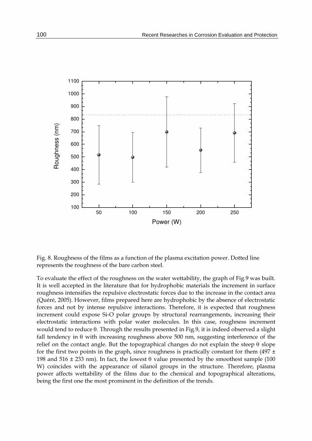
Another important aspect as one considers water wettability is surface topography. Changes in roughness alter the contact area of the droplet varying the intensity of the electrostatic forces. Figure 8 shows the roughness of the as-received (dotted line) and plasma deposited carbon steel as a function of P. In a general way, film deposition reduces the substrate roughness for any deposition condition employed here. Furthermore, the roughness upshifts just for the samples prepared at 150 and 250 W of power.
Recent Researches in Corrosion Evaluation and Protection
100
50 100 150 200 250100
200
300
400
500
600
700
800
900
1000
1100
Ro
ug
hn
ess (
nm
)
Power (W)
Fig. 8. Roughness of the films as a function of the plasma excitation power. Dotted line represents the roughness of the bare carbon steel.
To evaluate the effect of the roughness on the water wettability, the graph of Fig.9 was built. It is well accepted in the literature that for hydrophobic materials the increment in surface roughness intensifies the repulsive electrostatic forces due to the increase in the contact area (Quéré, 2005). However, films prepared here are hydrophobic by the absence of electrostatic forces and not by intense repulsive interactions. Therefore, it is expected that roughness increment could expose Si-O polar groups by structural rearrangements, increasing their electrostatic interactions with polar water molecules. In this case, roughness increment
would tend to reduce . Through the results presented in Fig.9, it is indeed observed a slight fall tendency in with increasing roughness above 500 nm, suggesting interference of the relief on the contact angle. But the topographical changes do not explain the steep slope for the first two points in the graph, since roughness is practically constant for them (497 ± 198 and 516 ± 233 nm). In fact, the lowest value presented by the smoothest sample (100 W) coincides with the appearance of silanol groups in the structure. Therefore, plasma power affects wettability of the films due to the chemical and topographical alterations, being the first one the most prominent in the definition of the trends.

Improvement of the Corrosion Resistance of Carbon Steel by Plasma Deposited Thin Films
101
500 550 600 650 70090
92
94
96
98
100
102
104
106C
on
tact A
ng
le ()
Roughness (nm)
50 W
100 W
150 W
200 W 250 W
Fig. 9. Contact angle as a function of the roughness of the films.
The corrosion of Si-containing films upon fluorine- and oxygen–rich environments is a matter of interest in microelectronic (Chen et al., 2011, Stillahn et al., 2011) and aerospace (Huang et al., 2011) applications, respectively. To evaluate the chemical response of the films to such media, samples were exposed to reactive plasmas generated from SF6 or O2. The etching rates derived from these experiments are presented in Fig. 10 as a function of the film deposition power. The removal of the layer material in SF6 plasmas is slower for the films prepared with 50 and 100 W and rises around 30% with increasing P to 150 and 200 W. Since the layers prepared with the highest power levels presented progressive loss of C-H groups and then silicon enrichment, structures with elevated proportions of Si-H and Si-O groups were formed. The affinity towards fluorine grows, consistently with the etching rate elevation. This interpretation is supported by the fact that etching rates similar to the reported to silicon wafers in SF6 plasmas (~ 90 nm/min) (Tian et al., 2000) were attained to the high power prepared samples. As materials with elevated etching rate and selectivity are desired for designing high aspect ratio microelectrical-mechanical systems, the films prepared with the highest power levels are potential candidates for this area.
It is interesting to note, however, that when the samples were exposed to oxygen plasmas, no material removal was detected by perfilometry indicating the formation of a structure highly resistant to oxygen attack, as required in several aerospace applications. Even though C is present in huge proportions, it is protected from oxygen attack by formation of a Si-O2 barrier on the film surface upon oxygen plasma (Bruce et al., 2010). From the moment this protection is created, further material removal is hampered, explaining the undetectable etching rates developed in the films studied here.

Recent Researches in Corrosion Evaluation and Protection
102
50 100 150 200
0
20
40
60
80
100E
tch
ing
Ra
te (n
m/m
in)
Power (W)
SF6 Plasma
O2 plasma
Fig. 10. Etching rate of the films in reactive SF6 and O2 plasmas as a function of the film deposition power.
The resistance of the carbon steel to corrosion in saline solution was evaluated by electrochemical impedance spectroscopy. The results of the phase angle are presented in
Fig.11 as a function of frequency, , for the bare and film-containing carbon steel. Measurements were performed varying the immersion time, t, from 0 to 180 minutes.
Considering the immersion time t = 0 min, the phase angle of the non-treated substrate increases with frequency reaching a maximum around 101 Hz and falling afterwards. This one concavity shape reflects the changes in the phase angle provoked by substrate-electrolyte interactions. After film deposition, the low frequency maximum is still detected but a more intense component arises in the high frequency region, affecting the overall shape of the curves. The second maximum is caused by electrolyte- film interactions and the presence of the two components suggests simultaneous reactions on the film and substrate surfaces. The enhancement in the high frequency component, accompanied by the diminution in the low frequency one, reveal a better performance of the system under the corrosive medium. For the sample prepared with 250 W no improvement was detected with respect to the bare steel since the film partially detached of the substrate. Comparing the phase angles at 105 Hz in the different graphs, it is noticed an evolution with increasing P: for the bare substrate it is lower than 10 and increases continuously, reaching 86 for the sample prepared in plasma of 200 W. Layers with phase angles close to 90 present a capacitive-like behavior, and act as good corrosion barriers. For the sample prepared with 150 W, the phase angle at 105 Hz is high but not stable with increasing t: a continuous fall is observed, reaching the same plateau detected for the bare substrate. Indeed, the shape of

Improvement of the Corrosion Resistance of Carbon Steel by Plasma Deposited Thin Films
103
10-1
100
101
102
103
104
105
0
10
20
30
40
50
60
70
80
90
Ph
ase
Ang
le ()
Frequency (Hz)
0 min
20 min
40 min
90 min
180 min
10-1
100
101
102
103
104
105
0
10
20
30
40
50
60
70
80
90
Ph
ase A
ngle
()
Frequency (Hz)
0 min
20 min
40 min
90 min
180 min
Steel P = 50 W
10-1
100
101
102
103
104
105
0
10
20
30
40
50
60
70
80
90
Ph
ase
An
gle
()
Frequency (Hz)
0 min
20 min
40 min
90 min
180 min
10-1
100
101
102
103
104
105
0
10
20
30
40
50
60
70
80
90
Pha
se
An
gle
()
Frequency (Hz)
0 min
20 min
40 min
90 min
180 min
P = 100 W P = 150 W
10-1
100
101
102
103
104
105
0
10
20
30
40
50
60
70
80
90
Pha
se
Ang
le ()
Frequency (Hz)
0 min
20 min
40 min
90 min
180 min
10-1
100
101
102
103
104
105
0
10
20
30
40
50
60
70
80
90
Pha
se A
ngle
()
Frequency (Hz)
0 min
20 min
40 min
90 min
180 min
P = 200 W P = 250 W
Fig. 11. Phase angle as a function of the frequency taken at different immersion times for the samples prepared on carbon steel in plasmas of different powers. Phase angle for the bare steel substrate is also presented.

Recent Researches in Corrosion Evaluation and Protection
104
this curve evolutes to that of the bare substrate if the test is conducted for 180 minutes. Although the film deposited with 100 W presented good results for zero immersion time, they were not preserved with increasing t. The treatments which presented the most stable results were those performed with 50 and 200 W, being the last one, the most effective for the corrosion protection of the carbon steel.
Figure 12 shows the impedance modulus as a function of frequency for the bare- and film-
containing carbon steel. In a general way, Z decreases with increasing , achieving the lowest impedance at the high frequency extreme. Independently of the deposition condition employed, film application upshifts the impedance curves, especially in the low frequency region. Considering the different immersion times, the samples exposed to 50 and 200 W plasmas presented high stability even after the longest test. On the other hand, a downshift is observed on the curves of the samples prepared in plasmas of 100, 150 and 250 W, indicating a deterioration of the protective properties upon the corrosion experiments. The lack of a specific trend with t in the curves of the sample deposited at 250 W may be a consequence of the non uniformity of the remaining layer left onto the substrate.
Using the method proposed in (Mansfeld, 1981), the total resistance Rt, was derived from the impedance modulus curves at the lowest frequency extreme (10-1 Hz) and the results are presented in Fig.13 as a function of the immersion time. Comparing the first point of each curve (t = 0 min) it is readily observed that the film deposited at 250 W provided no further resistance to the carbon steel. On the other hand, the film prepared with P = 150 W enhanced Rt by 2 orders of magnitude. Still better results were encountered for the samples exposed to plasmas of 50, 100 and 200 W. In these cases, Rt reached 1.5 X 10⁶, 2.5 X 10⁷ and
3.1 X 10⁶ , respectively, values substantially higher than the obtained for the bare substrate
(5.3 X 10² ). Nevertheless, these high impedance values decreased with increasing immersion time to 20 minutes, and kept practically unchanged afterwards. This constancy at elevated values is an important issue as one considers the preservation of the barrier properties under aggressive environments. Under the most aggressive condition employed
here (180 min), Rt was also observed to vary with P: it increases from 1.5 X 10⁵ to 5.4 X 10⁵ as P is changed from 50 to 200 W, that is an almost fourfold increase for this P range.
In order to interpret the results of Fig.13 it should be taken into account the effect of the film thickness on the corrosion protection, as depicted in Fig.14. The growth in Rt scales well with film thickness, except for the sample prepared in 150 W plasmas. In this case, another factor, besides thickness, seems to have a greater importance for the film performance.
Composition is also a relevant factor for corrosion resistance. In plasma deposited HMDSO films (Ul et al., 2002), the density is observed to increase with the proportion of Si-H bonds due to Si enrichment. From the results presented in Fig. 5, the Si-H proportion augments in the film with increasing P. According to this analysis, the densest layers were prepared in 150 and 250 W plasmas while the lightest ones were obtained in 50 and 100 W plasmas. Interestingly, in these extremes Si-H contents are separated by four orders of magnitude.
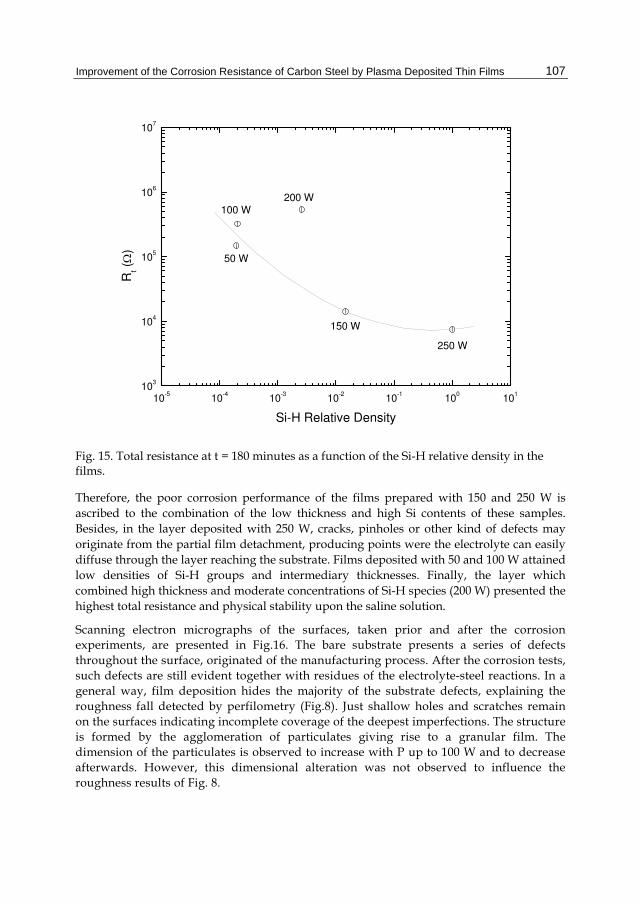
To determine the effect of the silicon content on Rt, the graph of Fig. 15 was built. Indeed, Rt tends to decrease with increasing Si-H density, except for the sample prepared at 200 W which associated intermediary Si proportions to high thickness values, factor that was determinant for the results found here.

Improvement of the Corrosion Resistance of Carbon Steel by Plasma Deposited Thin Films
105
10-1
100
101
102
103
104
105
101
102
103
104
105
106
107
108
|Z| ()
Frequency (Hz)
0 min
20 min
40 min
90 min
180 min
10-1
100
101
102
103
104
105
101
102
103
104
105
106
107
108
|Z| ( )
Frequency (Hz)
0 min
20 min
40 min
90 min
180 min
Steel P = 50 W
10-1
100
101
102
103
104
105
101
102
103
104
105
106
107
108
|Z| ()
Frequency (Hz)
0 min
20 min
40 min
90 min
180 min
10-1
100
101
102
103
104
105
101
102
103
104
105
106
107
108
|Z| (o
hm
)
Frequency (Hz)
0 min
20 min
40 min
90 min
180 min
P = 100 W P = 150 W
10-1
100
101
102
103
104
105
101
102
103
104
105
106
107
108
|Z| ()
Frequency (Hz)
0 min
20 min
40 min
90 min
180 min
10-1
100
101
102
103
104
105
101
102
103
104
105
106
107
108
Z (
)
Frequency (Hz)
0 min
20 min
40 min
90 min
180 min
P = 200 W P = 250 W
Fig. 12. Impedance modulus as a function of frequency taken at different immersion times for the samples prepared on carbon steel in plasmas excited with different powers. Impedance modulus for the bare steel substrate is also presented.

Recent Researches in Corrosion Evaluation and Protection
106
-20 0 20 40 60 80 100 120 140 160 180 20010
2
103
104
105
106
107
108
Rt ()
Immersion Time (min)
Steel P = 50 W P = 100 W P = 150 W P = 200 W P = 250 W
Fig. 13. Total resistance as a function of the immersion time for the samples exposed to plasmas of different powers and for the bare substrate.
0 2000 4000 6000 8000 1000010
3
104
105
106
107
250 W
200 W
100 W
50 W
Rt ()
Thickness (nm)
150 W
Fig. 14. Total resistance at t = 180 minutes as a function of the film thickness.
Improvement of the Corrosion Resistance of Carbon Steel by Plasma Deposited Thin Films
107
10-5
10-4
10-3
10-2
10-1
100
101
103
104
105
106
107
250 W
200 W100 W
50 W
Rt ()
Si-H Relative Density
150 W
Fig. 15. Total resistance at t = 180 minutes as a function of the Si-H relative density in the films.
Therefore, the poor corrosion performance of the films prepared with 150 and 250 W is
ascribed to the combination of the low thickness and high Si contents of these samples.
Besides, in the layer deposited with 250 W, cracks, pinholes or other kind of defects may
originate from the partial film detachment, producing points were the electrolyte can easily
diffuse through the layer reaching the substrate. Films deposited with 50 and 100 W attained
low densities of Si-H groups and intermediary thicknesses. Finally, the layer which
combined high thickness and moderate concentrations of Si-H species (200 W) presented the
highest total resistance and physical stability upon the saline solution.
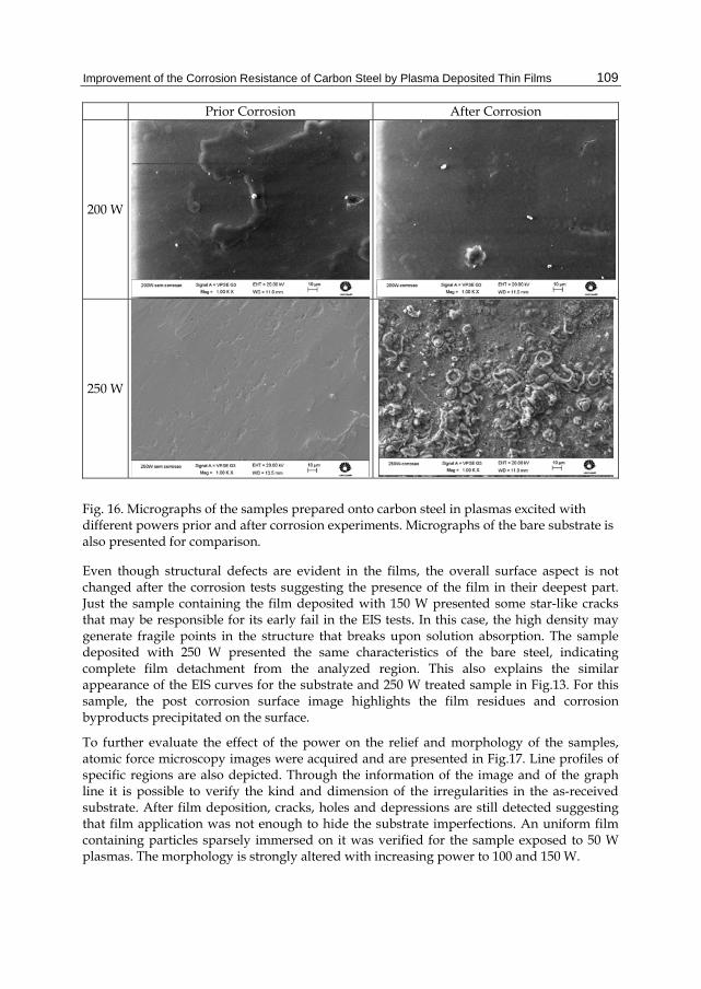
Scanning electron micrographs of the surfaces, taken prior and after the corrosion experiments, are presented in Fig.16. The bare substrate presents a series of defects throughout the surface, originated of the manufacturing process. After the corrosion tests, such defects are still evident together with residues of the electrolyte-steel reactions. In a general way, film deposition hides the majority of the substrate defects, explaining the roughness fall detected by perfilometry (Fig.8). Just shallow holes and scratches remain on the surfaces indicating incomplete coverage of the deepest imperfections. The structure is formed by the agglomeration of particulates giving rise to a granular film. The dimension of the particulates is observed to increase with P up to 100 W and to decrease afterwards. However, this dimensional alteration was not observed to influence the roughness results of Fig. 8.

Recent Researches in Corrosion Evaluation and Protection
108
Prior Corrosion After Corrosion
Steel
50 W
100 W
150 W
Improvement of the Corrosion Resistance of Carbon Steel by Plasma Deposited Thin Films
109
Prior Corrosion After Corrosion
200 W
250 W
Fig. 16. Micrographs of the samples prepared onto carbon steel in plasmas excited with different powers prior and after corrosion experiments. Micrographs of the bare substrate is also presented for comparison.
Even though structural defects are evident in the films, the overall surface aspect is not changed after the corrosion tests suggesting the presence of the film in their deepest part. Just the sample containing the film deposited with 150 W presented some star-like cracks that may be responsible for its early fail in the EIS tests. In this case, the high density may generate fragile points in the structure that breaks upon solution absorption. The sample deposited with 250 W presented the same characteristics of the bare steel, indicating complete film detachment from the analyzed region. This also explains the similar appearance of the EIS curves for the substrate and 250 W treated sample in Fig.13. For this sample, the post corrosion surface image highlights the film residues and corrosion byproducts precipitated on the surface.
To further evaluate the effect of the power on the relief and morphology of the samples, atomic force microscopy images were acquired and are presented in Fig.17. Line profiles of specific regions are also depicted. Through the information of the image and of the graph line it is possible to verify the kind and dimension of the irregularities in the as-received substrate. After film deposition, cracks, holes and depressions are still detected suggesting that film application was not enough to hide the substrate imperfections. An uniform film containing particles sparsely immersed on it was verified for the sample exposed to 50 W plasmas. The morphology is strongly altered with increasing power to 100 and 150 W.

Recent Researches in Corrosion Evaluation and Protection
110
(a) (b)
Steel
50 W
100 W
150 W

Improvement of the Corrosion Resistance of Carbon Steel by Plasma Deposited Thin Films
111
(a) (b)
200 W
250 W
Fig. 17. (a) Surface topographical images of the carbon steel exposed to plasmas of different powers. The image of the non coated substrate is also presented. (b) Surface profiles taken in specific points of each sample, indicated by the blue line in the respective image.
Particles of different sizes are arranged in a string-like granular structure. As power is
enhanced to 200 W, the regularity of this pattern is lost and the compact organization of the
particles suggests that there are connections amongst them. In this case, the stripes are
detected only in the depressions and the defect evident in the image is a result of the
incomplete covering of the substrate imperfections. Certainly, film is present in its bottom
part, preventing early corrosion fail in this sample. The lack of organization may be a
consequence of the higher fragmentation degree induced in the plasma phase with
increasing P. Finally, the results obtained in the sample exposed to 250 W plasmas confirm
that film was completely detached from the surface, remaining just small fragments
connected to it.
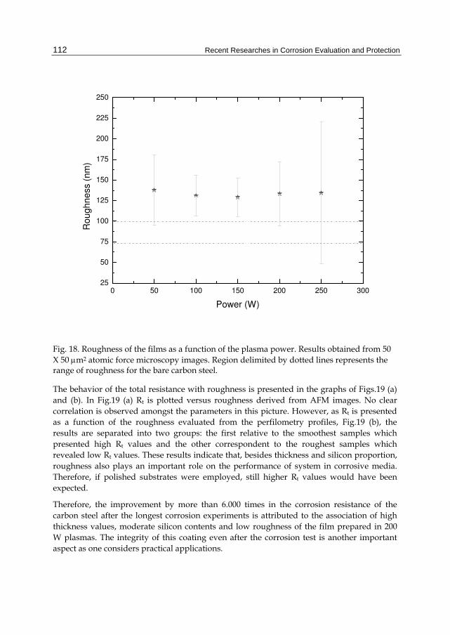
Roughness was also evaluated from the 50 X 50 m2 atomic force microscopy images and
the results are plotted as a function of the plasma excitation power in Fig.18. The interval
delineated by the dotted lines in the graph represents the range of roughness values for the
bare substrate. Film deposition tended to increase the roughness of the carbon steel for any
plasma excitation condition. Considering the scan length adopted in this case, the effect of
the substrate imperfections on the RMS roughness is reduced as compared to the obtained
in the results of Fig.8, determined by perfilometry. Even thought surface morphology is
strongly affected by changing the plasma excitation power it has no evident influence on
roughness which keeps roughly constant around 133 nm.
Recent Researches in Corrosion Evaluation and Protection
112
0 50 100 150 200 250 30025
50
75
100
125
150
175
200
225
250
R
ou
gh
ne
ss (
nm
)
Power (W)
Fig. 18. Roughness of the films as a function of the plasma power. Results obtained from 50
X 50 m2 atomic force microscopy images. Region delimited by dotted lines represents the range of roughness for the bare carbon steel.
The behavior of the total resistance with roughness is presented in the graphs of Figs.19 (a)
and (b). In Fig.19 (a) Rt is plotted versus roughness derived from AFM images. No clear
correlation is observed amongst the parameters in this picture. However, as Rt is presented
as a function of the roughness evaluated from the perfilometry profiles, Fig.19 (b), the
results are separated into two groups: the first relative to the smoothest samples which
presented high Rt values and the other correspondent to the roughest samples which
revealed low Rt values. These results indicate that, besides thickness and silicon proportion,
roughness also plays an important role on the performance of system in corrosive media.
Therefore, if polished substrates were employed, still higher Rt values would have been
expected.
Therefore, the improvement by more than 6.000 times in the corrosion resistance of the
carbon steel after the longest corrosion experiments is attributed to the association of high
thickness values, moderate silicon contents and low roughness of the film prepared in 200
W plasmas. The integrity of this coating even after the corrosion test is another important
aspect as one considers practical applications.

Improvement of the Corrosion Resistance of Carbon Steel by Plasma Deposited Thin Films
113
128 130 132 134 136 13810
3
104
105
106
250 W
200 W
100 W
50 W
Rt ()
Roughness (nm)
150 W
(a)
450 500 550 600 650 700 75010
3
104
105
106
107
250 W
200 W
100 W
50 W
Rt ()
Roughness (nm)
150 W
(b)
Fig. 19. Total resistance at t = 180 minutes as a function of roughness determined from AFM images (a) and from perfilometry profiles (b).

Recent Researches in Corrosion Evaluation and Protection
114
4. Conclusions
Molecular structure, chemical composition, morphology and topography of plasma
deposited HMDSO films were strongly dependent on the plasma excitation power. The
films are water repellent and present good adhesion to different substrates. Physical
stability was a problem just for the layer prepared with the highest power in which
thickness exceeded 10 m, but the reduction in the deposition time would easily solve this
drawback. All the other samples showed integrity even after aging in atmosphere
conditions. The different reactivities of the hybrid organic-inorganic structure towards
fluorine suggest it is a potential material for designing microelectromechanical devices.
Moreover, films are transparent to visible light and highly resistant to oxygen attack,
convenient properties as one considers the protection of a series of outdoor and space
devices. In saline solutions, the most aggressive medium for steels, film deposition was
observed to increase the corrosion resistance of the samples by more than 47.000 times.
Differently of the results found in a previous work, the protection lasted until the end of the
test, revealing an intact surface after the corrosion experiment. The optimum plasma
treatment condition was considered to be the conducted with 200 W of power, since it
provided the highest corrosion resistance for longer times. No intermediary oxide layer was
grown in the metal surface and then all the improvements are ascribed to the HMDSO
derived film. This opens the possibility of further improving the corrosion resistance of the
carbon steel by creation of a dense oxide layer onto the metallic substrate prior to film
deposition. New studies will be developed to evaluate this possibility. It should be finally
mentioned that the films produced here are not exclusive to carbon steel protection since
they adhere well to different substrates.
5. Acknowledgment
The authors would like to thank Brazilian agencies FAPESP and CNPq for financial support.
6. References
Biederman, H. e Osada, Y. 1992. Plasma Polymerization Processes. New York : Elsevier, 1992. Bruce, R.L.; Lin, T.; Phaneuf, R.J.; Oehrleinb, G.S.; Bell, W.; Long, B.; Willson, C.G. 2010.
Molecular structure effects on dry etching behavior of Si-containing resists in oxygen plasma. J. Vac. Sci. Technol. B. Jul 2010, Vol. 28, 4, pp. 751-757.
Chen, Q.; Zhang, D.; Tan, Z.; Wang, Z.; Liu, L.; Lu, J.Q. 2011. Thick benzocyclobutene etching using high density SF6/O2 plasmas. J. Vac. Sci. Technol. B. Jan 2011, Vol. 29, 1, pp. 011019-1 - 011019-6.
Choudhury, A.J.; Barve, S.A.; Chutia, J.; Pal, A.R.; Kishore, R.; Jagannath; Pande, M.; Patil, D.S. 2011. RF-PACVD of water repellent and protective HMDSO coatings on bell metal surfaces: Correlation between discharge parameters and film properties. Appl. Surf. Sci. Aug 2011, Vol. 257, pp. 8469-8477.
Choudhury, A.J.; Chutia, J.; Kakati, H.; Barve, S.A.; Pal, A.R.; Sarma, N.S.; Chowdhury, D.; Patil, D.S. Studies of radiofrequency plasma deposition of hexamethyldisiloxane films and their thermal stability and corrosion resistance behavior. Vacuum. Jun 2010, Vol. 84, 11.

Improvement of the Corrosion Resistance of Carbon Steel by Plasma Deposited Thin Films
115
Fracassi, F.; d'Agostino, R.; Palumbo, F.; Angelini, E.; Grassini, S.; Rosalbino, F. 2003. Application of plasma deposited organosilicon thin films for the corrosion protection of metals. Surf. Coat. Technol. Sep 2003, Vols. 174-175, pp. 107-111.
Gengenbach, T.R. e Griesser, H.J. 1999. Polymer. Post-deposition ageing reactions differ markedly between plasma polymers deposited from siloxane and silazane monomers. Aug 1999, Vol. 40, 18, pp. 5079-5094.
Guruvenket, S.; Azzi, M.; Li, D.; Szpunar, J.A.; Martinu, L.; Klemberg-Sapieha, J.E. 2010. Structural, mechanical, tribological, and corrosion properties of a-SiC:H coatings prepared by PECVD. Surf. Coat. Technol. Aug 2010, Vol. 204, 21-22, pp. 3358-3365.
Huang, Y.; Tian, X.; Lv, S.; Yang, S.; Fu, R.K.Y.; Chu, P.K.; Leng, J.; Li, Y. 2011. An undercutting model of atomic oxygen for multilayer silica/alumina films fabricated by plasma immersion implantation and deposition on polyimide. Appl. Surf. Sci. Aug 2011, Vol. 57, 21, pp. 9158-9163.
Koch, G.H.; Brongers, M.P.H.; Thompson, N.G.; Virmani, Y. P.; Payer, J.H. 2002. Corrosion costs and preventive strategies in the United States. Nace International. 2002. available at http://events.nace.org/publicaffairs/images_cocorr/ccsupp.pdf.
Lanford, W.A.; Rand, M.J. 1978. The hydrogen content of plasma‐deposited silicon nitride. J. App. Phys. Apr 1978, Vol. 49, 4, pp. 2473-2477.
Mansfeld, F. 1981. Recording and analysis of AC impedance data for corrosion studies: I. Background and methods of analysis. Corrosion. May 1981, Vol. 37, 5, pp. 301-307.
Morosoff, N. 1990. Plasma Deposition, Treatment and Etching of Polymers. [ed.] R. d'Agostino. New York : Academic Press, 1990.
Muntasser; Z.M.; Al-Darbi, M.M.; Islami, M.R., 2002. Corrosion. 2002. Quéré, D. 2005. Non-sticking drops. Rep. Prog. Phys. 68, Nov 2005, pp. 2495-2532. Radhakrishnan, S.; Sonawane, N.; Siju, C.R. 2009. Epoxy powder coatings containing
polyaniline for enhanced corrosion protection. Progress in Organic Coatings. Mar 2009, Vol. 64, 4, pp. 383-386.
Rao, A.P.; Rao, A.V. 2010. Modifying the surface energy and hydrophobicity of the low-density silica aerogels through the use of combinations of surface-modification agents. Journal of Materials Science. Jan 2010, Vol. 41, 1, pp. 51-63.
Ricci, M.; Dorier, J.; Hollestein, C.; Fayet, P. 2011. Influence of Argon and Nitrogen Admixture in HMDSO/O2 Plasmas onto Powder Formation. Plasma Process. Polym. Feb 2011, Vol. 8, 2, pp. 108-117.
Scheinmann, F. 1970. An introduction to spectroscopic methods for the identification of organic compounds. Oxford : Pergamon Press, 1970. Vol. 1.
Shin, A.S.; Shon, M.Y. 2010. Effects of coating thickness and surface treatment on the corrosion protection of diglycidyl ether bisphenol-A based epoxy coated carbon steel. Journal of Industrial and Engineering Chemistry. 16, Nov 2010, Vol. 6, pp. 884-890.
Stillahn, J.M., zhang, J., Fisherb, E.R. 2011. Surface interactions of SO2 and passivation chemistry during etching of Si and SiO2 in SF6/O2 plasmas. J. Vac. Sci. Technol. B. Jan 2011, Vol. 29, 1, pp. 011014-1 - 011014-10.
Tian, W.-C., Weigold, J.W., Pang, S.W. 2000. Comparison of Cl2 and F-based dry etching for high aspect ratio Si microstructures etched with an inductively coupled plasma source. J. Vac. Sci. Technol. B. Jul 2000, Vol. 18, 4, pp. 1890-1896.

Recent Researches in Corrosion Evaluation and Protection
116
Ul, C.V.; Roux, F.; Laporte, C.B.; Pastol, J.L.; Chausse, A. 2002. Hexamethyldisiloxane (HMDSO)-plasma-polymerised coatings as primer for iron corrosion protection: influence of RF bias. J. Mater. Chem. Jun 2002, Vol. 12, 8, pp. 2318-2324.
Ul, C.V.; Laporte, C.B.; Benissad, N.; Chausse, A.; Leprince, P.; Messina, R. 2000. Plasma-polymerized coatings using HMDSO precursor for iron protection. Progress in Organic Coatings. Feb 2000, Vol. 38, 1, pp. 9-15.
Yasuda, H. 1985. Plasma Polymerization. New York : Academic Press, 1985.

Recent Researches in Corrosion Evaluation and ProtectionEdited by Prof. Reza Shoja Razavi
ISBN 978-953-307-920-2Hard cover, 152 pagesPublisher InTechPublished online 25, January, 2012Published in print edition January, 2012
InTech EuropeUniversity Campus STeP Ri Slavka Krautzeka 83/A 51000 Rijeka, Croatia Phone: +385 (51) 770 447 Fax: +385 (51) 686 166www.intechopen.com
InTech ChinaUnit 405, Office Block, Hotel Equatorial Shanghai No.65, Yan An Road (West), Shanghai, 200040, China
Phone: +86-21-62489820 Fax: +86-21-62489821
The purpose of this book is to present and discuss the recent methods in corrosion evaluation and protection.The book contains six chapters. The aim of Chapter 1 is to demonstrate that Electrochemical ImpedanceSpectroscopy can be a very useful tool to provide a complete evaluation of the corrosion protection propertiesof electro-coatings. Chapter 2 presents results of studies of materials degradation from experimentalelectrochemical tests and theoretical calculations. Chapter 3 deals with the presentation of the corrosion andcorrosion prevention of the aluminum alloys by organic coatings and inhibitors. Chapter 4 addresses the newmethod of pigment preparation that can improve protection efficiency. The effectiveness of plasma depositedfilms on the improvement of carbon steel corrosion resistance is discussed in Chapter 5. Chapter 6 deals withthe conjugation of carbon nanotubes with organic-inorganic hybrid to prepare hybrid coatings that combinehigh anti-corrosion efficiency with elevated mechanical resistance.
How to referenceIn order to correctly reference this scholarly work, feel free to copy and paste the following:
Rita C.C. Rangel, Tagliani C. Pompeu, José Luiz S. Barros Jr., César A. Antonio,Nazir M. Santos, Bianca O.Pelici, Célia M.A. Freire, Nilson C. Cruz and Elidiane C. Range (2012). Improvement of the CorrosionResistance of Carbon Steel by Plasma Deposited Thin Films, Recent Researches in Corrosion Evaluation andProtection, Prof. Reza Shoja Razavi (Ed.), ISBN: 978-953-307-920-2, InTech, Available from:http://www.intechopen.com/books/recent-researches-in-corrosion-evaluation-and-protection/improvement-of-the-corrosion-resistance-of-carbon-steel-by-plasma-deposited-thin-films