Embed Size (px)
Citation preview
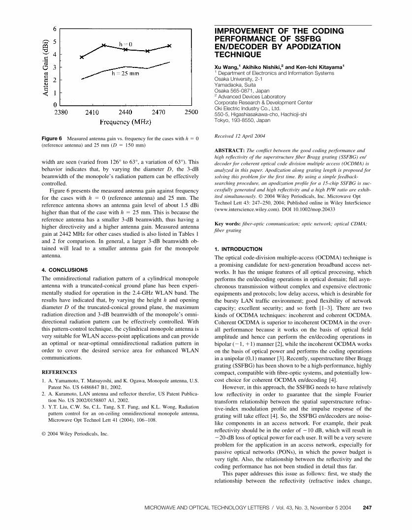
width are seen (varied from 126° to 63°, a variation of 63°). Thisbehavior indicates that, by varying the diameter D, the 3-dBbeamwidth of the monopole’s radiation pattern can be effectivelycontrolled.
Figure 6 presents the measured antenna gain against frequencyfor the cases with h � 0 (reference antenna) and 25 mm. Thereference antenna shows an antenna gain level of about 1.5 dBihigher than that of the case with h � 25 mm. This is because thereference antenna has a smaller 3-dB beamwidth, thus having ahigher directiveity and a higher antenna gain. Measured antennagain at 2442 MHz for other cases studied is also listed in Tables 1and 2 for comparison. In general, a larger 3-dB beamwidth ob-tained will lead to a smaller antenna gain for the monopoleantenna.
4. CONCLUSIONS
The omnidirectional radiation pattern of a cylindrical monopoleantenna with a truncated-conical ground plane has been experi-mentally studied for operation in the 2.4-GHz WLAN band. Theresults have indicated that, by varying the height h and openingdiameter D of the truncated-conical ground plane, the maximumradiation direction and 3-dB beamwidth of the monopole’s omni-directional radiation pattern can be effectively controlled. Withthis pattern-control technique, the cylindrical monopole antenna isvery suitable for WLAN access-point applications and can providean optimal or near-optimal omnidirectional radiation pattern inorder to cover the desired service area for enhanced WLANcommunications.
REFERENCES
1. A. Yamamoto, T. Matsuyoshi, and K. Ogawa, Monopole antenna, U.S.Patent No. US 6486847 B1, 2002.
2. A. Kuramoto, LAN antenna and reflector therefor, US Patent Publica-tion No. US 2002/0158807 A1, 2002.
3. Y.T. Liu, C.W. Su, C.L. Tang, S.T. Fang, and K.L. Wong, Radiationpattern control for an on-ceiling omnidirectional monopole antenna,Microwave Opt Technol Lett 41 (2004), 106–108.
© 2004 Wiley Periodicals, Inc.
IMPROVEMENT OF THE CODINGPERFORMANCE OF SSFBGEN/DECODER BY APODIZATIONTECHNIQUE
Xu Wang,1 Akihiko Nishiki,2 and Ken-Ichi Kitayama1
1 Department of Electronics and Information SystemsOsaka University, 2-1Yamadaoka, SuitaOsaka 565-0871, Japan2 Advanced Devices LaboratoryCorporate Research & Development CenterOki Electric Industry Co., Ltd.550-5, Higashiasakawa-cho, Hachioji-shiTokyo, 193-8550, Japan
Received 12 April 2004
ABSTRACT: The conflict between the good coding performance andhigh reflectivity of the superstructure fiber Bragg grating (SSFBG) en/decoder for coherent optical code division multiple access (OCDMA) isanalyzed in this paper. Apodization along grating length is proposed forsolving this problem for the first time. By using a simple feedback-searching procedure, an apodization profile for a 15-chip SSFBG is suc-cessfully generated and high reflectivity and a high P/W ratio are exhib-ited simultaneously. © 2004 Wiley Periodicals, Inc. Microwave OptTechnol Lett 43: 247–250, 2004; Published online in Wiley InterScience(www.interscience.wiley.com). DOI 10.1002/mop.20433
Key words: fiber-optic communication; optic network; optical CDMA;fiber grating
1. INTRODUCTION
The optical code-division multiple-access (OCDMA) technique isa promising candidate for next-generation broadband access net-works. It has the unique features of all optical processing, whichperforms the en/decoding operations in optical domain; full asyn-chronous transmission without complex and expensive electronicequipments and protocols; low delay access, which is desirable forthe bursty LAN traffic environment; good flexibility of networkcapacity; excellent security; and so forth [1–3]. There are twokinds of OCDMA techniques: incoherent and coherent OCDMA.Coherent OCDMA is superior to incoherent OCDMA in the over-all performance because it works on the basis of optical fieldamplitude and hence can perform the en/decoding operations inbipolar (�1, �1) manner [2], while the incoherent OCDMA workson the basis of optical power and performs the coding operationsin a unipolar (0,1) manner [3]. Recently, superstructure fiber Bragggrating (SSFBG) has been shown to be a high-performance, highlycompact, compatible with fibre-optic systems, and potentially low-cost choice for coherent OCDMA en/decoding [4].
However, in this approach, the SSFBG needs to have relativelylow reflectivity in order to guarantee that the simple Fouriertransform relationship between the spatial superstructure refrac-tive-index modulation profile and the impulse response of thegrating will take effect [4]. So, the SSFBG en/decoders are noise-like components in an access network. For example, their peakreflectivity should be in the order of �10 dB, which will result in�20-dB loss of optical power for each user. It will be a very severeproblem for the application in an access network, especially forpassive optical networks (PONs), in which the power budget isvery tight. Also, the relationship between the reflectivity and thecoding performance has not been studied in detail thus far.
This paper addresses this issue as follows: first, we study therelationship between the reflectivity (refractive index change,
Figure 6 Measured antenna gain vs. frequency for the cases with h � 0(reference antenna) and 25 mm (D � 150 mm)
MICROWAVE AND OPTICAL TECHNOLOGY LETTERS / Vol. 43, No. 3, November 5 2004 247
�neff) and the coding performance of the SSFBG; then we proposea method to improve the performance of the SSFBG en/decoder byapodization.
2. CONFLICT BETWEEN THE CODING PERFORMANCE ANDHIGH REFLECTIVITY OF SSFBG
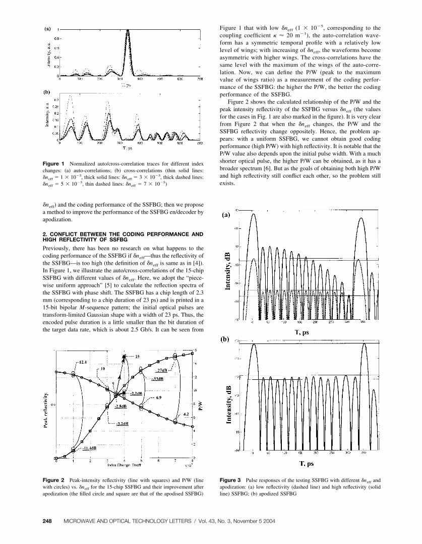
Previously, there has been no research on what happens to thecoding performance of the SSFBG if �neff—thus the reflectivity ofthe SSFBG—is too high (the definition of �neff is same as in [4]).In Figure 1, we illustrate the auto/cross-correlations of the 15-chipSSFBG with different values of �neff. Here, we adopt the “piece-wise uniform approach” [5] to calculate the reflection spectra ofthe SSFBG with phase shift. The SSFBG has a chip length of 2.3mm (corresponding to a chip duration of 23 ps) and is printed in a15-bit bipolar M-sequence pattern; the initial optical pulses aretransform-limited Gaussian shape with a width of 23 ps. Thus, theencoded pulse duration is a little smaller than the bit duration ofthe target data rate, which is about 2.5 Gb/s. It can be seen from
Figure 1 that with low �neff (1 � 10�5, corresponding to thecoupling coefficient � � 20 m�1), the auto-correlation wave-form has a symmetric temporal profile with a relatively lowlevel of wings; with increasing of �neff, the waveforms becomeasymmetric with higher wings. The cross-correlations have thesame level with the maximum of the wings of the auto-corre-lation. Now, we can define the P/W (peak to the maximumvalue of wings ratio) as a measurement of the coding perfor-mance of the SSFBG: the higher the P/W, the better the codingperformance of the SSFBG.
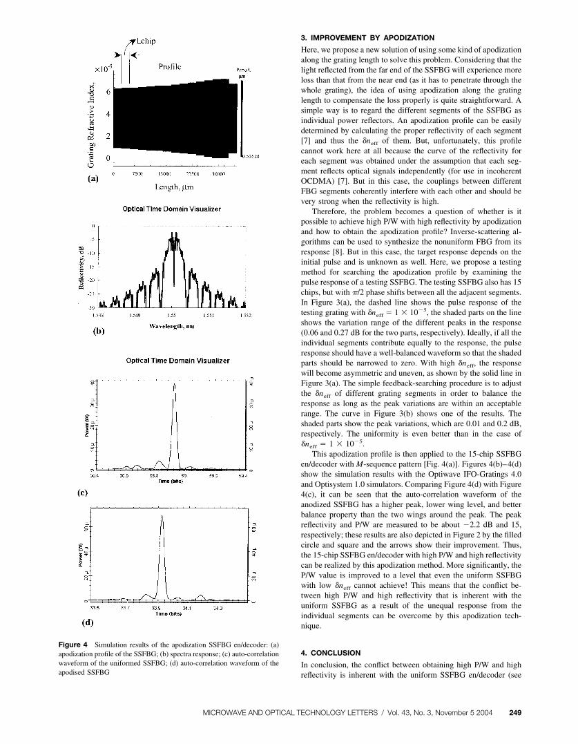
Figure 2 shows the calculated relationship of the P/W and thepeak intensity reflectivity of the SSFBG versus �neff (the valuesfor the cases in Fig. 1 are also marked in the figure). It is very clearfrom Figure 2 that when the �neff changes, the P/W and theSSFBG reflectivity change oppositely. Hence, the problem ap-pears: with a uniform SSFBG, we cannot obtain good codingperformance (high P/W) with high reflectivity. It is notable that theP/W value also depends upon the initial pulse width. With a muchshorter optical pulse, the higher P/W can be obtained, as it has abroader spectrum [6]. But as the goals of obtaining both high P/Wand high reflectivity still conflict each other, so the problem stillexists.
Figure 1 Normalized auto/cross-correlation traces for different indexchanges: (a) auto-correlations; (b) cross-correlations (thin solid lines:�neff � 1 � 10�5, thick solid lines: �neff � 3 � 10�5, thick dashed lines:�neff � 5 � 10�5, thin dashed lines: �neff � 7 � 10�5)
Figure 2 Peak-intensity reflectivity (line with squares) and P/W (linewith circles) vs. �neff for the 15-chip SSFBG and their improvement afterapodization (the filled circle and square are that of the apodised SSFBG)
Figure 3 Pulse responses of the testing SSFBG with different �neff andapodization: (a) low reflectivity (dashed line) and high reflectivity (solidline) SSFBG; (b) apodized SSFBG
248 MICROWAVE AND OPTICAL TECHNOLOGY LETTERS / Vol. 43, No. 3, November 5 2004
3. IMPROVEMENT BY APODIZATION
Here, we propose a new solution of using some kind of apodizationalong the grating length to solve this problem. Considering that thelight reflected from the far end of the SSFBG will experience moreloss than that from the near end (as it has to penetrate through thewhole grating), the idea of using apodization along the gratinglength to compensate the loss properly is quite straightforward. Asimple way is to regard the different segments of the SSFBG asindividual power reflectors. An apodization profile can be easilydetermined by calculating the proper reflectivity of each segment[7] and thus the �neff of them. But, unfortunately, this profilecannot work here at all because the curve of the reflectivity foreach segment was obtained under the assumption that each seg-ment reflects optical signals independently (for use in incoherentOCDMA) [7]. But in this case, the couplings between differentFBG segments coherently interfere with each other and should bevery strong when the reflectivity is high.
Therefore, the problem becomes a question of whether is itpossible to achieve high P/W with high reflectivity by apodizationand how to obtain the apodization profile? Inverse-scattering al-gorithms can be used to synthesize the nonuniform FBG from itsresponse [8]. But in this case, the target response depends on theinitial pulse and is unknown as well. Here, we propose a testingmethod for searching the apodization profile by examining thepulse response of a testing SSFBG. The testing SSFBG also has 15chips, but with �/2 phase shifts between all the adjacent segments.In Figure 3(a), the dashed line shows the pulse response of thetesting grating with �neff � 1 � 10�5, the shaded parts on the lineshows the variation range of the different peaks in the response(0.06 and 0.27 dB for the two parts, respectively). Ideally, if all theindividual segments contribute equally to the response, the pulseresponse should have a well-balanced waveform so that the shadedparts should be narrowed to zero. With high �neff, the responsewill become asymmetric and uneven, as shown by the solid line inFigure 3(a). The simple feedback-searching procedure is to adjustthe �neff of different grating segments in order to balance theresponse as long as the peak variations are within an acceptablerange. The curve in Figure 3(b) shows one of the results. Theshaded parts show the peak variations, which are 0.01 and 0.2 dB,respectively. The uniformity is even better than in the case of�neff � 1 � 10�5.
This apodization profile is then applied to the 15-chip SSFBGen/decoder with M-sequence pattern [Fig. 4(a)]. Figures 4(b)–4(d)show the simulation results with the Optiwave IFO-Gratings 4.0and Optisystem 1.0 simulators. Comparing Figure 4(d) with Figure4(c), it can be seen that the auto-correlation waveform of theanodized SSFBG has a higher peak, lower wing level, and betterbalance property than the two wings around the peak. The peakreflectivity and P/W are measured to be about �2.2 dB and 15,respectively; these results are also depicted in Figure 2 by the filledcircle and square and the arrows show their improvement. Thus,the 15-chip SSFBG en/decoder with high P/W and high reflectivitycan be realized by this apodization method. More significantly, theP/W value is improved to a level that even the uniform SSFBGwith low �neff cannot achieve! This means that the conflict be-tween high P/W and high reflectivity that is inherent with theuniform SSFBG as a result of the unequal response from theindividual segments can be overcome by this apodization tech-nique.
4. CONCLUSION
In conclusion, the conflict between obtaining high P/W and highreflectivity is inherent with the uniform SSFBG en/decoder (see
Figure 4 Simulation results of the apodization SSFBG en/decoder: (a)apodization profile of the SSFBG; (b) spectra response; (c) auto-correlationwaveform of the uniformed SSFBG; (d) auto-correlation waveform of theapodised SSFBG
MICROWAVE AND OPTICAL TECHNOLOGY LETTERS / Vol. 43, No. 3, November 5 2004 249
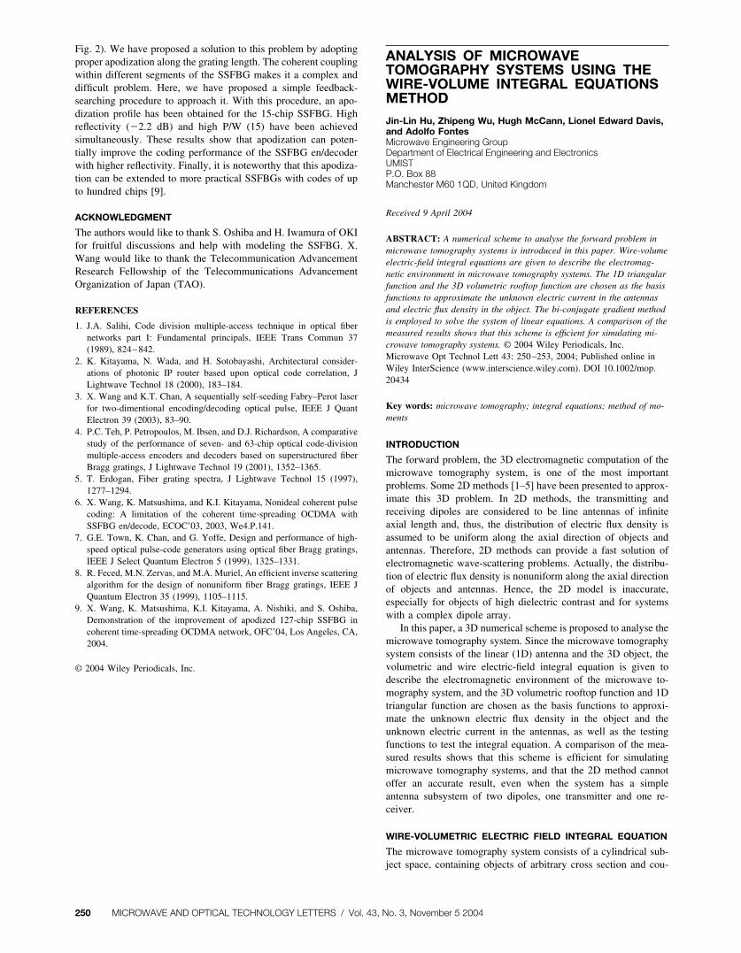
Fig. 2). We have proposed a solution to this problem by adoptingproper apodization along the grating length. The coherent couplingwithin different segments of the SSFBG makes it a complex anddifficult problem. Here, we have proposed a simple feedback-searching procedure to approach it. With this procedure, an apo-dization profile has been obtained for the 15-chip SSFBG. Highreflectivity (�2.2 dB) and high P/W (15) have been achievedsimultaneously. These results show that apodization can poten-tially improve the coding performance of the SSFBG en/decoderwith higher reflectivity. Finally, it is noteworthy that this apodiza-tion can be extended to more practical SSFBGs with codes of upto hundred chips [9].
ACKNOWLEDGMENT
The authors would like to thank S. Oshiba and H. Iwamura of OKIfor fruitful discussions and help with modeling the SSFBG. X.Wang would like to thank the Telecommunication AdvancementResearch Fellowship of the Telecommunications AdvancementOrganization of Japan (TAO).
REFERENCES
1. J.A. Salihi, Code division multiple-access technique in optical fibernetworks part I: Fundamental principals, IEEE Trans Commun 37(1989), 824–842.
2. K. Kitayama, N. Wada, and H. Sotobayashi, Architectural consider-ations of photonic IP router based upon optical code correlation, JLightwave Technol 18 (2000), 183–184.
3. X. Wang and K.T. Chan, A sequentially self-seeding Fabry–Perot laserfor two-dimentional encoding/decoding optical pulse, IEEE J QuantElectron 39 (2003), 83–90.
4. P.C. Teh, P. Petropoulos, M. Ibsen, and D.J. Richardson, A comparativestudy of the performance of seven- and 63-chip optical code-divisionmultiple-access encoders and decoders based on superstructured fiberBragg gratings, J Lightwave Technol 19 (2001), 1352–1365.
5. T. Erdogan, Fiber grating spectra, J Lightwave Technol 15 (1997),1277–1294.
6. X. Wang, K. Matsushima, and K.I. Kitayama, Nonideal coherent pulsecoding: A limitation of the coherent time-spreading OCDMA withSSFBG en/decode, ECOC’03, 2003, We4.P.141.
7. G.E. Town, K. Chan, and G. Yoffe, Design and performance of high-speed optical pulse-code generators using optical fiber Bragg gratings,IEEE J Select Quantum Electron 5 (1999), 1325–1331.
8. R. Feced, M.N. Zervas, and M.A. Muriel, An efficient inverse scatteringalgorithm for the design of nonuniform fiber Bragg gratings, IEEE JQuantum Electron 35 (1999), 1105–1115.
9. X. Wang, K. Matsushima, K.I. Kitayama, A. Nishiki, and S. Oshiba,Demonstration of the improvement of apodized 127-chip SSFBG incoherent time-spreading OCDMA network, OFC’04, Los Angeles, CA,2004.
© 2004 Wiley Periodicals, Inc.
ANALYSIS OF MICROWAVETOMOGRAPHY SYSTEMS USING THEWIRE-VOLUME INTEGRAL EQUATIONSMETHOD
Jin-Lin Hu, Zhipeng Wu, Hugh McCann, Lionel Edward Davis,and Adolfo FontesMicrowave Engineering GroupDepartment of Electrical Engineering and ElectronicsUMISTP.O. Box 88Manchester M60 1QD, United Kingdom
Received 9 April 2004
ABSTRACT: A numerical scheme to analyse the forward problem inmicrowave tomography systems is introduced in this paper. Wire-volumeelectric-field integral equations are given to describe the electromag-netic environment in microwave tomography systems. The 1D triangularfunction and the 3D volumetric rooftop function are chosen as the basisfunctions to approximate the unknown electric current in the antennasand electric flux density in the object. The bi-conjugate gradient methodis employed to solve the system of linear equations. A comparison of themeasured results shows that this scheme is efficient for simulating mi-crowave tomography systems. © 2004 Wiley Periodicals, Inc.Microwave Opt Technol Lett 43: 250–253, 2004; Published online inWiley InterScience (www.interscience.wiley.com). DOI 10.1002/mop.20434
Key words: microwave tomography; integral equations; method of mo-ments
INTRODUCTION
The forward problem, the 3D electromagnetic computation of themicrowave tomography system, is one of the most importantproblems. Some 2D methods [1–5] have been presented to approx-imate this 3D problem. In 2D methods, the transmitting andreceiving dipoles are considered to be line antennas of infiniteaxial length and, thus, the distribution of electric flux density isassumed to be uniform along the axial direction of objects andantennas. Therefore, 2D methods can provide a fast solution ofelectromagnetic wave-scattering problems. Actually, the distribu-tion of electric flux density is nonuniform along the axial directionof objects and antennas. Hence, the 2D model is inaccurate,especially for objects of high dielectric contrast and for systemswith a complex dipole array.
In this paper, a 3D numerical scheme is proposed to analyse themicrowave tomography system. Since the microwave tomographysystem consists of the linear (1D) antenna and the 3D object, thevolumetric and wire electric-field integral equation is given todescribe the electromagnetic environment of the microwave to-mography system, and the 3D volumetric rooftop function and 1Dtriangular function are chosen as the basis functions to approxi-mate the unknown electric flux density in the object and theunknown electric current in the antennas, as well as the testingfunctions to test the integral equation. A comparison of the mea-sured results shows that this scheme is efficient for simulatingmicrowave tomography systems, and that the 2D method cannotoffer an accurate result, even when the system has a simpleantenna subsystem of two dipoles, one transmitter and one re-ceiver.
WIRE-VOLUMETRIC ELECTRIC FIELD INTEGRAL EQUATION
The microwave tomography system consists of a cylindrical sub-ject space, containing objects of arbitrary cross section and cou-
250 MICROWAVE AND OPTICAL TECHNOLOGY LETTERS / Vol. 43, No. 3, November 5 2004