Embed Size (px)
Citation preview
IIUUSSTT IInntteerrnnaattiioonnaall JJoouurrnnaall ooff EEnnggiinneeeerriinngg SScciieennccee,, VVooll.. 1199,, NNoo..55--11,, 22000088,, PPaaggee 112277--113366
IIMMPPRROOVVEEMMEENNTT OOFF SSIIMMPPLLEE AANNDD RREEGGEENNEERRAATTIIVVEE GGAASS TTUURRBBIINNEE UUSSIINNGG SSIIMMPPLLEE AANNDD EEJJEECCTTOORR--AABBSSOORRPPTTIIOONN
RREEFFRRIIGGEERRAATTIIOONN
L. Garooci Farshi, S. M. Seyed Mahmoudi & A. H. Mosafa
Abstract: The exhaust gases of gas turbine power plant carry a significant amount of thermal energy that is usually expelled to the atmosphere; this causes a reduction in net work and efficiency of gas turbine.� On the other hand, the generated power and efficiency of gas turbine plants depend largely on the temperature of the inlet air, So that they both increase as the inlet air temperature decreases. The mentioned two problems can be solved by installing an absorption refrigeration cycle (ARC) at gas turbine inlet, working with thermal energy of exhaust gases. In this research, effect of inlet air cooling on gas turbine performance is studied. The work shows that, the net work and the efficiency will increase by 6-10% and 1-5% respectively for every 10°C decrease of inlet temperature. Since, coefficient of performance (COP) of ARC is low, with high pressure ratios in simple gas turbine (SGT) and with low pressure ratios in regenerative gas turbine (RGT), thermal energy of exhaust gases can not supply all the needed thermal energy for refrigeration cycle. The results show that, when an ejector is included in refrigeration cycle, the need for external energy source required for refrigeration cycle is reduced.
Keywords: Gas Turbine, Inlet Air Cooling, Absorption Refrigeration, Ejector, Regenerative Gas Turbine
1. Introduction1
Gas turbines are known to have a number of attractive features, principally: low capital cost, compact size, short delivery, high flexibility, fast starting and loading, lower manpower operating needs, not needing to water sources and better environmental performance, compared with other electricity producing devices specially the steam turbine. However, it suffers from relatively lower efficiency and strong influence of climate conditions specially temperature on its behavior. Also thermal energy of exhaust gases is delivered to and wasted in the environment. This low grade thermal energy can be put to beneficial use in a heat exchanger of RGT and/or generator of absorption refrigeration cycle to increase the power and efficiency of gas turbine plants.
Paper first received May. 10, 2007 and in revised form Nov. 02, 2009. L. Garooci Farshi, is PhD student of Mechanical Engineering, Tabriz University. [email protected] S.M. Seyed Mahmoudi is Assistant Prof. of Mechanical Engineering Department, Tabriz University. [email protected] A.H. Mosafa is PhD student of Mechanical Engineering, Tabriz University. [email protected]
In recent years, several researches have been carried out to enhance performance of gas turbine plants by using an ARC for inlet air cooling. J. Sigler et al [1] used an ammonia-water absorption machine for inlet cooling in a combined cycle and found out that implementation of inlet cooling using absorption chilling is an attractive option for plant power augmentation from an engineering and economic point of view. E. Kakaras et al [2] present the possibilities and advantages from the integrated of an absorption air-cooling system with gas turbine to reduce the intake-air temperature. They concluded that at any location, the net output power can increase by at least 10%. A.M. Bassily [3] introduced an absorption inlet-cooling system to the intercooled, reheat, recuperated gas-turbine cycle and showed that applying absorption inlet-cooling could increase the efficiency of the cycle by up to 6.6%. This increase was 3.9%when evaporative inlet cooling was utilized. J. Wang and J.S. Chiou [4] considered an existing Frame 7B simple cycle gas turbine as the basic system and converted it into the modified system with either the inlet air cooling or/and steam injection features. They showed that, under the condition of local summer
id22848281 pdfMachine by Broadgun Software - a great PDF writer! - a great PDF creator! - http://www.pdfmachine.com http://www.broadgun.com
Dow
nloa
ded
from
ijie
pr.iu
st.a
c.ir
at 1
7:42
IRD
T o
n F
riday
Jun
e 22
nd 2
018

128 IImmpprroovveemmeenntt ooff ssiimmppllee aanndd rreeggeenneerraattiivvee ggaass ttuurrbbiinnee uussiinngg ssiimmppllee aanndd eejjeeccttoorr��
weather, the benefits obtained from the system implementing both steam injection and inlet air cooling features are more than a 70% boost in power and 20.4% improvement in heat rate. M. Ameri and S.H. Hejazi [5] presented an overview of an intake air-cooling system that uses an absorption chiller and an air cooler in the Chabahar power plant. They obtained that, by using this technique the output power will increase by 11.3%. In another work E. Kakaras et al [6] presented a computer simulation of the integration of an innovative absorption chiller technology for reducing the intake-air temperature in simple gas turbine and a combined cycle plants. The air cooling system demonstrated a higher gain in power output and efficiency than evaporative cooling for a simple gas turbine, independent of ambient air temperature. The results for the combined cycle test case also demonstrated that the absorption chiller can considerably increase the power output, although there is an efficiency reduction.
B. Dawoud et al [7] evaluated the effect of several inlet air cooling techniques on gas-turbine power plants in two locations; namely, Marmul and Fahud, in Oman using typical meteorological year data. The LiBr�H2O cooling offers 40% and 55% more output energy than fogging cooling at Fahud and Marmul, respectively. All of these works show an increase of power and efficiency of gas turbine by reducing inlet air temperature. These articles have investigated the effect of inlet air cooling, however, in addition to this, we have studied the amount of thermal energy of exhaust gases and their ability to satisfy the required thermal energy of refrigeration cycle in different conditions of both cycles. For this study we have modeled gas turbine, ejector and absorption refrigeration cycle, and compared the experimental results of simple gas turbine [8] with our results at the same condition to verify the model; see table 1.
Tab. 1. The results of verifying the SGT model
WH W501D5 ABB GT10 GE MS9331 GE LM2500 Gas Turbine
14.2 14 15 18.9 Pressure Ratio 1180 1218 1353 1258 Turbine Inlet Temperature [C] 535 555 610 532 experimental
537.5 561.6 623.6 527.6 our model Turbine Outlet Temperature [C]
32.8 33.3 35 34.6 experimental 34.6 34.3 34.5 36.8 our model
Efficiency[%]
295 315 380 315 experimental 315.2 327.5 374.2 340.7 our model
Specific Net Work[kJ/kg]
The study shows that, with some pressure ratio (rc) of gas turbine, because of low COP of ARC, energy of exhaust gases can not provide all needed energy of refrigeration system to have a low and constant inlet temperature. Using ejector in absorption refrigeration system brings about the advantages of absorption and ejector refrigeration systems and provides high COP. So that, the range of rc with which the thermal energy of exhaust gas of both SGT and RGT is enough for refrigeration cycle, is extended. A number of models have been suggested to study the effect of utilizing ejector in absorption refrigeration cycle to increase the COP. D. W. Sun Et al [9] combined an ejector cycle and LiBr absorption refrigeration cycle to bring together the advantages of the two conventional cycles. The novel cycle was particularly suitable for being powered by waste thermal energy. S. Wu and I. W. Eames [10] suggested another combination of ejector and absorption refrigeration cycle. It was complicated than the Sun�s cycle, but the effect
of using ejector was approximatly the same. N. H. Aly et al [11] described a computer simulation model for steam jet ejector. They used a method similar to that used in reference [9]. Alexis and Rogdakis [12] described two simple methods. In the first, an ejector
draws vapour from an evaporator and discharges it to a condenser, in the second, an ejector draws vapour from an evaporator and discharges it to an absorber. The first model gave higher COP than the second one. Sözen
and Özalp [13] and Sözen and Yücesu [14] studied an ejector absorption refrigeration cycle in which the ejector was located at the absorber inlet. A. Levy et al [15] studied the performance of an advanced triple-pressure level (TPL) single-stage absorption cycle with refrigerant R125 and various organic absorbents. In the developed TPL cycle, a jet ejector of a special design is used at the absorber inlet. We have used LiBr absorption refrigeration cycle with an ejector at condenser inlet because of , simplicity, 3higher COP and having an environment friendly working fluid. The system was similar to that used by Wen Sun [9].
2. Assumptions
Following typical operating parameters are considered for gas turbine in this work [3], [4]:
1. polytropic efficiency of compressor (∞,c) and turbine (∞,t) are 0.9 and 0.85 respectively. 2. Methane (CH4) with low heat value of 50010 kJ/kg is used as fuel and its pressure and temperature are the same as that of combustion chamber inlet.
Dow
nloa
ded
from
ijie
pr.iu
st.a
c.ir
at 1
7:42
IRD
T o
n F
riday
Jun
e 22
nd 2
018

L. Garooci Farshi, S. M. Seyed Mahmoudi & A. H. Mosafa 112299
3. Combustion efficiency (cc) is 0.98 and its pressure drop is 5% of combustion chamber inlet pressure. 4. Pressure drop of both compressor inlet and turbine outlet is 1kPa. 5. Heat exchanger efficiency in RGT (HE) is 0.85. 6. Mechanical efficiency (m) is 0.98. 7. ISO standard conditions for inlet air is T = 15C, P = 100kPa and ö = 60%. 8. Minimum Stack temperature is 100C. 9. Minimum inlet temperature to prevent icing at the compressor inlet is 12C.
Following parameters were chose for the studying of ejector absorption refrigeration cycle[9], [10]: 10. Condenser temperature (Tcond) = 45C, absorber temperature (Tabs) = 45C, evaporator temperature (Teva) = 8C, generator temperature (Tgen) = 95C, heat exchanger efficiency in refrigeration cycle (ex) = 90%, generator pressure (Pgen) = 10KPa, ejector area ratio (Ar) = 10, nozzle efficiency (n) and diffuser efficiency (d) are 90%. A parametric study was carried out changing one parameter at a time and keeping the others fixed. For ARC the assumptions are similar to these values, except that
condcond gen sat TP P P (condsat TP is saturated
pressure at Tcond ) and Ar , n and d are omitted.
3. Studied Cycle and Used Equations for
Simulation Fig. 1 shows RGT with Ejector- Absorption
Refrigeration Cycle (EARC). When we study the effect of inlet air cooling in SGT, heat exchanger will be omitted; and when we want to use ARC, we omit the ejector and line 13 of steam. An ejector integrated in this way into the ARC increase the refrigerant flow rate from the evaporator and therefore raises the cooling capacity of the machine. Thermodynamic analysis of each component is given briefly below: 3-1. Compressor
From following equation, for given inlet conditions, rc, and compressor polytropic efficiency, T2gen can be estimated:
gt
gt
gt
gt
P
P c
T
T
aP dPP
R
T
dTC
2
1
2
1 , (1)
Assuming an adiabatic flow, compressor specific work (for 1 kg of inlet air) can be calculated from: (Ma is molecular mass of inlet air)
a
T
T
aP
c M
dTC
w
gt
gt
2
1 (2)
Fig. 1. RGT with EARC
3-2. Combustion Chamber
Combustion reaction for a fuel with chemical formula of CnHm with considering humidity of the air can be written as:
22
22
222
)4)(1()4(76.3
276.4)4(
)76.476.3()4(
OmnNmn
OHmmnnCO
OHNOmnHC mn
(3)
We assume that, the combustion process is complete and nitrogen dose not participate in reaction. Excess Air Coefficient () can be calculated from The first law of thermodynamics for an adiabatic combustion process for any given turbine inlet temperature (TIT); and then the fuel-air ratio (f) can be calculated from Eq.(4) by considering a value for cc. ( is Molar humidity ratio)
ccaMmn
mnf
)1(76.4)4/(
12
(4)
3-3. Heat Exchanger
In the heat exchanger the exhaust gas from the turbine is used to heat air before it enters the combustion chamber, and therefore the fuel consumption is reduced in the combustion chamber. The energy balance for this process is:
gt
gte
gtc
gt
T
T pg
T
T pa dtCfdtC4
2
)1(
(5)
For calculating Tcgt and Tegt we use heat exchanger effectiveness equation in addition to Eq. (5):
gt
gt
cgt
gt
T
T pa
T
T pa
HE
dtC
dtC
4
2
2
(6)
Dow
nloa
ded
from
ijie
pr.iu
st.a
c.ir
at 1
7:42
IRD
T o
n F
riday
Jun
e 22
nd 2
018
130 IImmpprroovveemmeenntt ooff ssiimmppllee aanndd rreeggeenneerraattiivvee ggaass ttuurrbbiinnee uussiinngg ssiimmppllee aanndd eejjeeccttoorr��
3-4. Turbine Turbine outlet temperature for a given TIT, rc, and
∞,t can be estimated from:
gt
gt
gt
gt
P
P t
T
T
gP dPP
R
T
dTC
3
4
3
4 , (7)
In this equation gPC , will be calculated from Eq. (8):
3
4
3
4 ,1
P
P t
T
T
gP dPP
R
T
dTC
(8)
Assuming no heat transfer from the turbine, turbine specific work can also be evaluated from:
g
T
T
gP
t M
dTC
fw
gt
gt
3
4)1(
(9)
Analyzing the performance of modern gas turbine engines without prediction of the cooling air flow, leads to inaccurate results as this flow is a large fraction of the inlet air flow in these machines. As cooling flows are complex functions of turbine operating and design parameters accurate modeling of cooling air flow is a complex task [16-20]. For a general thermodynamic analysis of gas turbine with blade cooling, it is better to use a much simpler computing procedure which requires little input data and gives reasonably accurate results. Therefore for estimation of cooling air we chose the model developed by Sarabchi [21]. 3-5. Inlet Air Cooling of Compressor
The first thermodynamic law is used for calculating cooling load of refrigeration cycle: In this equation subscripts da, v and L express dry air, water vapor and liquid water respectively.
gtLgtambambvambambda
gtvgtgtdaeva
hhh
hhQ
1,1,,
1,11,
)()(
)(
(10)
Humidity ratio (Ȧ) for given relative humidity (ij) can be estimated from:
P
Psat
622.0 (11)
3-6. EARC
The operation of the EARC is characterized by the generator, condenser, absorber and evaporator temperatures and the refrigerant entrainment ratio. The concentration of LiBr in weak and strong solutions at the absorber and generator is specified by their
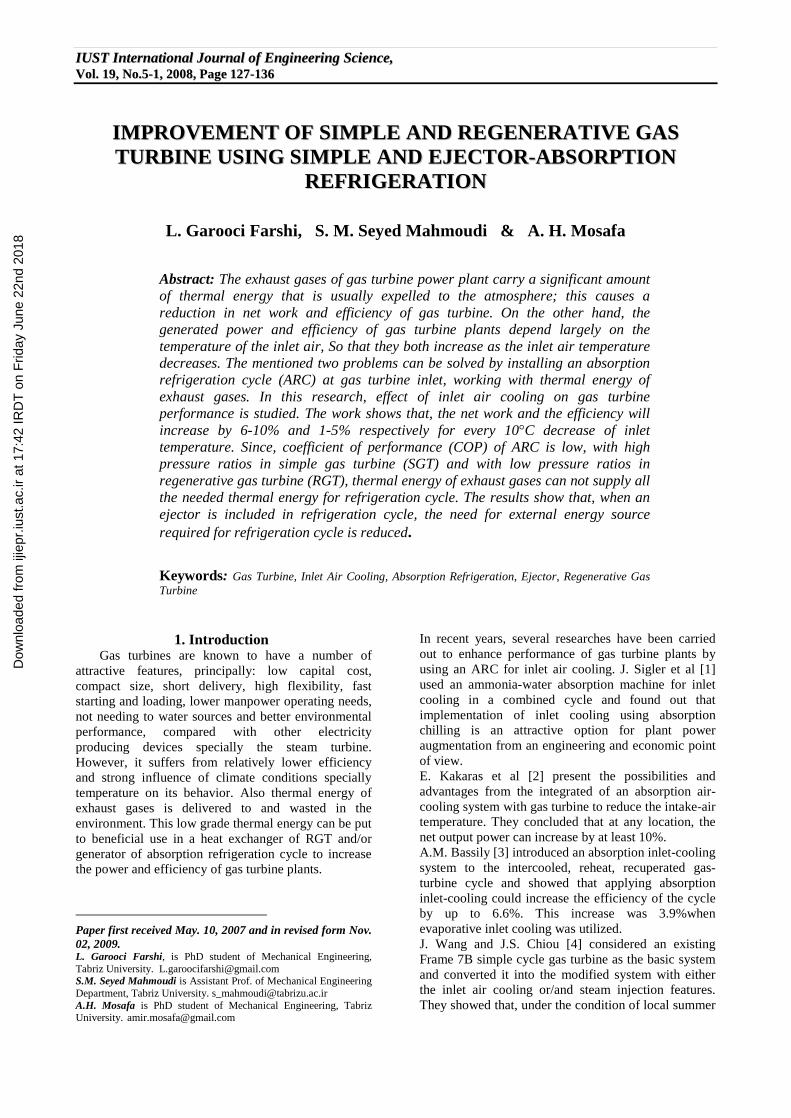
respective pressures and temperatures. Therefore the cycle can be analyzed as it is presented in ref.[9]. 4. Effect of Inlet Air Cooling on SGT and RGT
Power and Efficiency Specific work of SGT and RGT as a function of compressor inlet temperature (T0) with different rc and turbine inlet temperature (TIT) is shown in Fig. 2 and Fig. 3 respectively.
Fig. 2. Effect of compressor inlet air temperature on SGT specific work in different rc and TIT (ö0=60%)
Fig. 3. Effect of compressor inlet air temperature on
RGT specific work in different rc and TIT (ö0=60%)
These schemes show that, as T0 increases, specific work decreases. This variation is linear. The slop of this line increases with a rise in rc and decreases slightly with rise in TIT. Fig. 2 and Fig. 3 show a comparison of specific work of SGT and RGT. In both figures, specific work increases with rc to the maximum specific work that occurs in optimum rc and then decreases. For each TIT the optimum rc is given in Table. 2 that shows the maximum specific work and optimum rc increases as TIT rises and this is expected from ideal cycle equations [22].
Dow
nloa
ded
from
ijie
pr.iu
st.a
c.ir
at 1
7:42
IRD
T o
n F
riday
Jun
e 22
nd 2
018

L. Garooci Farshi, S. M. Seyed Mahmoudi & A. H. Mosafa 113311
Tab. 2. The effect of TIT on gas turbine maximum specific work obtained with an optimum amount of
rc (ö0=60%, T0=15C) Max wnet [kJ/kg] rc TIT [C]
289.5 13.08 1100 339.2 17.5 1250 394.8 20.1 1400
Efficiency of SGT and RGT as a function of T0 with different rc and TITs is shown in Fig. 4 and Fig. 5 respectively. From these schemes, it is clear that efficiency of SGT and RGT decreases with an increase in inlet temperature and the amount of decrease increases with an increase of rc. Efficiency of SGT increases with rc to the maximum amount that occurs in optimum rc and then decreases. For each TIT, the optimum rc is given in Table. 3. The efficiency of RGT decreases with an increase of rc , because, when rc increases, temperature of gases in outlet of turbine decrease and temperature of air in outlet of compressor increases, so, the recovered thermal energy in heat exchanger falls until zero corresponding to the rc that at this point efficiency of SGT and RGT equals. These pressure ratios are presented in Table. 4 for each TIT. For higher values of rc the heat exchanger would cool the air leaving the compressor and so reduce the efficiency.
Fig. 4. Effect of compressor inlet air temperature on
SGT efficiency in different rc and TIT (ö0=60%)
Fig. 5. Effect of compressor inlet air temperature on
RGT efficiency in different rc and TIT (ö0=60%)
Tab. 3. Effect of TIT on SGT maximum efficiency and its rc (ö0=60%, T0=15C)
Max Cycle [%] rc TIT [C] 39.42 35.98 1100 40.94 47.6 1250 42.57 62.6 1400
Tab. 4. Maximum rc for RGT with different TITs.
1400 1250 1100 TIT [C] 29 24 19 rc
5. Density Change of Inlet Air
It is mentioned that the adverse effect of high inlet air temperature on the power output and efficiency of a gas turbine is twofold: 1. A higher intake air temperature results in an increase of the specific compressor work, and therefore, in a reduction of power output and efficiency 2. Each gas turbine has a constant volumetric flow rate of air; so, as the air temperature increases, the air density and, consequently, its mass flow rate decreases. The reduced air mass flow rate directly causes the gas turbine to produce less output power. The first case is studied in previous sections. In this section we study the second case. Fig. 6 shows the air density variation with temperature. It shows that, output power will increase by a percentage of about 3.4 for every 10 C of inlet air temperature decrease.�
Fig. 6. Effect of temperature on density of air [23]
6. Cooling Capacities Obtainable From the SGT and RGT Exhaust Gases in ARC and
EARC In previous sections, it was shown that a decrease
of compressor inlet air temperature causes an increase of efficiency and specific work of gas turbine. In this section we will consider, the required cooling capacity (Qeva) to have a specified temperature and humidity in compressor inlet air, the required thermal energy in generator (Qgan) to achieve the cooling capacity and the thermal energy available in exhaust gases (Qgen,available) of SGT and RGT. In Fig. 7, Qeva is shown as a function of ambient temperature (Tamb) at the compressor inlet conditions.
Dow
nloa
ded
from
ijie
pr.iu
st.a
c.ir
at 1
7:42
IRD
T o
n F
riday
Jun
e 22
nd 2
018

132 IImmpprroovveemmeenntt ooff ssiimmppllee aanndd rreeggeenneerraattiivvee ggaass ttuurrbbiinnee uussiinngg ssiimmppllee aanndd eejjeeccttoorr��
Fig. 7. Required cooling capacity for inlet air cooling as a function of ambient temperature
(T0=12C, amb=60%, 0=60%)
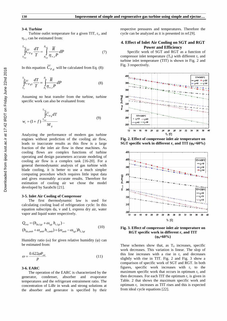
It indicates that, an increase of Tamb causes an increase of Qeva to achieve compressor inlet condition (T0=12°C, 0= 60%). To achieve the cooling capacity, Qgan of ARC and EARC is calculated as a function of Tamb and it is shown in Figs. 8-9 respectively. It is clear that when Tamb increases Qgan increases too. Also, Fig. 9 shows increase of Qgan with increase of Pgan and with decrease of Ar. Figs. 10-13 show the variation of Qgan with refrigeration system parameters for ARC and Figs. 14-17 show these variations for EARC. In general, Qgan of EARC is lower than that of ARC because of ejector presence that increases COP of refrigeration cycle. In both ARC and EARC, Qgan increases with increase of absorber, condenser, generator temperatures and decrease of evaporator temperature. Also, in EARC, Qgan increases when Pgan increases and/or Ar decreases, but we will focus on the same parameters of EARC and ARC (absorber, condenser, generator and evaporator temperatures).
Fig. 8. ARC required energy as a function of
ambient temperature for providing specified inlet cooling (T0=12C, amb=60%, 0=60%)
Fig 9: EARC required energy as a function of ambient temperature, Pgan and Ar for providing specified inlet
cooling (T0=12C, amb=60%, 0=60%)
Fig 10: ARC required energy as a function of Tabs�for
providing specified inlet cooling (Tamb=25C, T0=12C, amb=60%, 0=60%)
Fig 11: ARC required energy as a function of Tcond�for
providing specified inlet cooling (Tamb=25C, T0=12C, amb=60%, 0=60%)
Fig. 12. ARC required energy as a function of Teva�
for providing specified inlet cooling (Tamb=25C, T0=12C, amb=60%, 0=60%)
Fig. 13. ARC required energy as a function of Tgen�
for providing specified inlet cooling (Tamb=25C, T0=12C, amb=60%, 0=60%)
Dow
nloa
ded
from
ijie
pr.iu
st.a
c.ir
at 1
7:42
IRD
T o
n F
riday
Jun
e 22
nd 2
018
L. Garooci Farshi, S. M. Seyed Mahmoudi & A. H. Mosafa 113333
Fig. 14. EARC required energy as a function of Tabs,
Pgan and Ar for providing specified inlet cooling (Tamb=25C, T0=12C, amb=60%, 0=60%)
Fig. 15. EARC required energy as a function of Tcond�, Pgan and Ar for providing specified inlet
cooling (Tamb=25C, T0=12C, amb=60%, 0=60%)
Fig. 16. EARC required energy as a function of Teva,�
Pgan and Ar for providing specified inlet cooling (Tamb=25C, T0=12C, amb=60%, 0=60%)
Fig. 17. EARC required energy as a function of Tgen �
Pgan and Ar for providing specified inlet cooling (Tamb=25C, T0=12C, amb=60%, 0=60%)
Dow
nloa
ded
from
ijie
pr.iu
st.a
c.ir
at 1
7:42
IRD
T o
n F
riday
Jun
e 22
nd 2
018
134 IImmpprroovveemmeenntt ooff ssiimmppllee aanndd rreeggeenneerraattiivvee ggaass ttuurrbbiinnee uussiinngg ssiimmppllee aanndd eejjeeccttoorr��
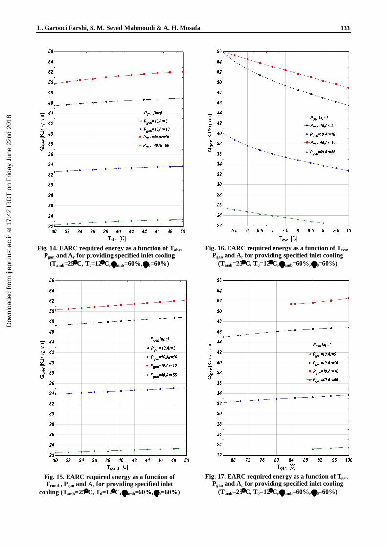
In order to study the amount of required energy that can be provided from exhaust gases, available energy in exhaust gases of SGT and RGT is presented in Fig. 18 and Fig. 19 with different TITs.
Fig. 18. Thermal energy of SGT exhaust gases as a
function of rc and TIT (T0=12C, 0=60%)
The effective factors in the amount of Qgen,available are rc and TIT. From the Figures it is clear that, for SGT, Qgen,available decreases with increase of rc as the turbine outlet temperature falls. But in RGT the trend is inverse because of decreased recovered thermal energy in heat exchanger. In both SGT and RGT Qgen,available increases with an increase of TIT.
Fig. 19. Thermal energy of RGT exhaust gases as a
function of rc and TIT (T0=12C, 0=60%)
Now, we characterize the conditions with which Qgan can be supplied from Qgen,available. The tables 5-7 are obtained from a comparison of Figs. 8-17 with Figs. 18-19. Table 5 shows the Variation of rc with ambient temperature with which Qgan equals to Qgen,available for all studied cycles. This table indicates that, for SGT, in all rc lower than that mentioned in the table, Qgan can be provided from Qgen,available completely, but for RGT with rc higher than mentioned in table, up to the value given in Table. 4 for each TIT, Qgan can be supplied from Qgen,available. The same discussion can be made for Tables 6 and 7, which show the effect of TIT and different parameters of refrigeration cycle on the rc with which Qgan equals to Qgen,available.
Tab. 5. Variation of Qgen�and Qgen,available� equivalence rc with ambient temperature (TIT=1250C)
EARC ARC
rc (RGT)
rc (SGT)
Qgen=Qgen,available
[kJ/kg air] rc
(RGT) rc
(SGT) Qgen=Qgen,available
[kJ/kg air] Tamb[C]
13 38.9 34.81 15.14 34.52 56.81 25 17.5 30.8 78.42 23.85 23.98 128 35 21.2 26.4 108.6 31.9 19 177.2 40
Tab. 6. Variation of Qgen�and Qgen,available� equivalence rc with TIT(Tamb=25C)
EARC ARC
rc (RGT)
rc (SGT)
Qgen=Qgen,available
[kJ/kg air] rc
(RGT) rc
(SGT) Qgen=Qgen,available
[kJ/kg air] TIT[C]
15.18 24.7 34.81 17.35 21.9 56.81 1100 13 38.9 34.81 15.4 34.52 56.81 1250
10.35 37.5 34.81 12.29 56.91 56.81 1400
Dow
nloa
ded
from
ijie
pr.iu
st.a
c.ir
at 1
7:42
IRD
T o
n F
riday
Jun
e 22
nd 2
018

L. Garooci Farshi, S. M. Seyed Mahmoudi & A. H. Mosafa 113355
Tab. 7. Variation of Qgen�and Qgen,available� equivalence rc with parameters of refrigeration cycle(Tamb=25C, T0=12C, amb=60%, 0=60%, TIT=1250C)
EARC ARC
rc��
(RGT)��
rc��
(SGT)��
Qgen=Qgen,available
[kJ/kg air]��
rc��
(RGT)��
rc��
(SGT)��
Qgen=Qgen,available
[kJ/kg air]��Tgen[C]
12.75��39.35 32.74��14.73 35.27��52.86��75��12.85��39.3��33.15��14.85��35.04��54.04��85��
13��38.9��34.81��15.14��34.54��56.81��95������Teva[C]
13.5��37.7��40.2��15.42 34��59.61��5��13��38.9��34.81��15.14��34.52��56.81��8��
12.08��39.35��32.72��15.04��34.7��55.98��10������Tabs[C]
12.85��39.3 33.07��14.85��35��54.2��30��13��38.9��34.81��15.4��34.52��56.84��45��
14.15��36.4��46.92��15.8��33.35��63.34��50������Tcond[C]
12.9��39.1��33.9��14.94��34.85��54.96��30��13��38.9��34.81��15.4��34.52��56.81��45��
13.05��38.85��35.13��15.9��33.2��64.15��50��
It is shown that, by using ejector in refrigeration cycle, the range of rc that, the thermal energy of exhaust gases is enough for refrigeration cycle is extended in both SGT and RGT.
7. Conclusions
In this research firstly the effect of inlet air cooling on performance of gas turbine is studied. In both SGT and RGT cycles a reduction of inlet temperature showed an increase of power and efficiency especially with high rc . The maximum power and efficiency of SGT and the rc corresponding to these maximum amounts increased with a decrease of inlet temperature. These values are presented in Tables 8 and 9. These tables show that, the maximum specific work and efficiency of SGT increases 1.9% and 1.6% respectively with every 5°C decrease of inlet air temperature. It is clear that, the maximum specific work of RGT behaves like SGT and their amounts are the same approximately. Also, it is shown that for SGT, with low rc exhaust gases have enough thermal energy to supply required energy of ARC, but in RGT, with low rc exhaust gases do not carry enough energy to provide all required energy of ARC. In SGT with high rc exhaust gases do not provide the needed energy for ARC.
Tab. 8. Effect of compressor inlet air temperature
on SGT maximum specific work and its rc (TIT=1250C)
Max Wnet
[kJ/kg air] rc T0[C]
343 16.4 12 339.2 16.11 15 333 15.65 20
312.2 14.12 40
Tab. 9. Effect of compressor inlet air temperature on SGT maximum efficiency and its rc
(TIT=1250C) Max cycle
[%] rc T0[C]
41.32 49.05 12 40.94 47.6 15 40.32 45.34 20 37.86 38.02 40
Utilization of ejector decreases required energy of refrigeration system, so that, the range of rc with which, the thermal energy of exhaust gases is enough for refrigeration cycle is extended for both SGT and RGT cycles. Finally, the effect of refrigeration cycle parameters on the range of rc with which Qgan can be provided from Qgen,available completely is studied. It was shown that, Qgan decreases with a decrease of absorber, condenser, generator temperatures and an increase of evaporator temperature in both ARC and EARC and Qgan decreases with a decrease of Pgan. Therefore with these variations the mentioned range of rc will be extended.
References
[1] Sigler, J., Erickson, D., Blanco, H.P., Gas Turbine Inlet Cooling Using Absorption Refrigeration: a Comparison Based on a Combined Cycle Process, ASME TURBO EXPO, GT-0408, 2001.
[2] Kakaras, E., Doukelis, A., Scharfe, J., Application of Gas
Turbine Plants with Cooled Compressor Intake Air, ASME TURBO EXPO, GT-0110, 2001.
[3] Bassily, A.M., Performance Improvements of the Intercooled Reheat Recuperated Gas-Turbine Cycle Using Absorption Inlet-Cooling and Evaporative After-Cooling, Applied Energy, 77, 2004, pp. 249-272.
Dow
nloa
ded
from
ijie
pr.iu
st.a
c.ir
at 1
7:42
IRD
T o
n F
riday
Jun
e 22
nd 2
018

136 IImmpprroovveemmeenntt ooff ssiimmppllee aanndd rreeggeenneerraattiivvee ggaass ttuurrbbiinnee uussiinngg ssiimmppllee aanndd eejjeeccttoorr��
[4] Wang, F.J., Chiou, J.S., Integration of Steam Injection and Inlet air Cooling for a Gas Turbine Generation System, Energy Convesion and Management, 45, 2004, pp. 15-26.
[5] Ameri, M., Hejazi, S.H., The Study of Capacity
Enhancement of the Chabahar Gas Turbine Installation Using an Absorption Chiller, Applied Thermal Engineering, 24, 2004, pp. 59-68.
[6] Kakaras, E., Doukelis, A., Karellas, S., Compressor
Intake-Air Cooling in Gas Turbine Plants, Journal of Energy, 29, 2004, pp. 2347-2358.
[7] Dawoud, B., Zurigat, Y.H., Bortmany, J., Thermodynamic
Assessment of Power Requirement and Impact of Different gas Turbine Inlet Air Cooling Techniques at Two Different Location in Oman, Applied Thermal Engineering, 25, 2005, pp. 1579-1598.
[8] Sarabchi, K., Performance Evaluation of Reheat Gas
Turbine Cycle, Journal Power & Energy 218, 2004. [9] Sun, D.W., Eames, I.W., Aphornratana, S., Evaluation of
a Novel Combined Ejector- Absorption Refrigeration Cycle- i: Copmputer Simulation, Int J Refrigeration., 19 1996, pp. 172-180.
[10] Wu, S., Eames, I.W., A Novel Absorption- Recompression
Refrigeration Cycle. Applied Thermal Eng., 18, 1998, pp. 1149-1157.
[11] Aly, N.H., Karameldin, A., Shamloul, M.M., Modelling
and Simulation of Jet Ejectors, Journal of Desalination, 123, 1999, pp. 1-8.
[12] Alexis, G.K., Rogdakis, E.D., Performance Characteristics
of Two Combined Ejector-Absorption Cycle, Applied Thermal Eng, 22, 2002, pp. 97-106.
[13] Sözen, A., Özalp, M., Performance Improvement of
Absorption Refrigeration System Using Triple- Pressure- Level, Applied Thermal Engineering 23, 2003, pp. 1577-1593.
[14] Sözen, A., Yücesu, H.S., Performance Improvement of
Absorption Heat Transformer, Renewable Energy, 32, 2007, pp. 267�284.
[15] Levy, A., Jelinek, M., Borde, I., Ziegler, F.,
Performance of an Advanced Absorption Cycle with R125 and Different Absorbents, Energy, 29, 2004, pp. 2501�2515.
[16] De Paepe, M., Dick, E., Cycle Improvement to Steam
Injected Gas Turbine, Journal of Energy Res., 2000, pp. 1081-1107.
[17] Von Karman Institute For Fluid Dynamics, Film
Cooling And Turbine Blade Heat Transfer, Lecture series, 1-2, 1982.
[18] El-Masri, M.A., On� Thermodynamics of Gas-Turbine Cycle: Part 2- a Model for Expansion in Cooled Turbine, Journal of Engineering for Gas Turine and Power, 108, 1986, pp. 151-159.
[19] Erbes, M.R., Gay, R.R., Cohn, A., A Simulation Code for Analysis of Gas Turbine Power Plants, ASME paper 89-GT-39, 1989.
[20] Stecco, S.S., Facchini, B., A Computer Model for
Cooled Expansion in Gas Turbine. In proceedings of 3rd ASME Cogen Turbo Conference, France, 1989.
[21] Sarabchi, K., A Simple Approach to Gas Turbines
Modeling. In proceeding of Al Azhar Engineering 6th International Conference, Cairo, Egypt, 2000.
[22] Cohen, H., Rogers, G., Saravanamuto, H., Gas Turbine
Theory, 3rd ed., Longman, Scientific and Technical, Singapore, 1987.
[23] Kays, W.M., Crawford, M., Convective Heat and Mass
Transfer, 3rd ed., Mc Graw-Hill, 1995.
Dow
nloa
ded
from
ijie
pr.iu
st.a
c.ir
at 1
7:42
IRD
T o
n F
riday
Jun
e 22
nd 2
018
![REGENERATIVE BRAKING SYSTEM IN ELECTRIC VEHICLES · REGENERATIVE BRAKING SYSTEM IN ELECTRIC VEHICLES ... REGENERATIVE BRAKING SYSTEM ... Regenerative action during braking[9]](https://img.pdfslide.us/doc/110x75/5adccef67f8b9a1a088c7cf0/regenerative-braking-system-in-electric-vehicles-braking-system-in-electric-vehicles.jpg)