Embed Size (px)
Citation preview
SEGi Review ISSN 1985-5672
Vol. 4, No. 1, July 2011, 44-55 Corresponding author. E-mail: [email protected]
44
IMPROVEMENT OF A SOLAR HEATING PANEL’S THERMAL EFFICIENCY:
PARABOLIC TROUGH EFFECT COUPLED WITH A POROUS PACKED BED
Weng-Kheen Yeong1, Yin-Ling Lai
1, *Ji-Jinn Foo
1, 2
1School of Engineering, SEGi University College, Kota Damansara, Malaysia;
2Department of Mechanical Engineering, Sheffield University, United Kingdom.
ABSTRACT
The effects of hydrostatic, hydrodynamic, porosity and pressure drop on the heat
transfer characteristics of a solar heating panel incorporating a parabolic
trough collector (PTC) and porous packed bed are investigated experimentally.
The results show that a solar collector installed with only a PTC is able to
improve the thermal absorption of the working fluid. Through the addition of a
porous media into parts of the receiver tubes, the thermal efficiency of the
collector can be further enhanced. The heat transfer performance increases with
the decrease in porosity and mass flow rate. It is also found that a porous
medium is able to increase the rate of heat transfer during the transient
hydrostatic experiment, whereas the rate of heat transfer remains constant in the
hydrodynamic study where non-local-thermal-equilibrium (NLTE) becomes
dominant. Lastly, it is critical to form a non-sintered porous packed bed using
particles with uniform diameters to avoid extra internal pressure losses.
1.0 Introduction Solar power is a versatile form of renewable energy that can be utilized in many
applications from water distillation and power plants to food factories (Price et. al., 2002;
Odeh and Morrison, 2006; Dev and Tiwari, 2009). Malaysia is an equatorial country; it
receives approximately six hours of daily solar radiation intensity between 410 and
830W/m2 (Dev and Tiwari, 2009; Othman et. al., 1996). Such useful natural energy can
generally be used in two different applications: (i) Direct utilization to increase the
working fluid temperature for further usage, for instance: in a Rankine steam cycle; and (ii)
Electricity generation through photovoltaic cells (Kalogirou, 2004).
In 2009, Dev and Tiwari reported that the solar radiation intensity varies between 170W/m2
(7 AM, morning), 820W/m2 (12 PM, afternoon), and 180W/m
2 (17 PM, evening). Thus, the
performance of a solar heating panel strongly depends on the solar radiation received
throughout a day. This energy can be maximized and reutilized by using a solar light
tracking concentrator and a focal receiver. Past findings proved that with the aid of PTC
the thermal efficiency of a solar heating panel can be further enhanced (EI Fadar et. al.,
2009). The heat can be generated at a temperature between 50oC and 400
oC, even with a
light structure and using low cost technology. To construct a PTC, it is required to bend a
reflective material into a parabolic shape; more importantly, the parabolic sheet has to be
coupled with black metal tube enclosed within a vacuum glass tube to avoid heat losses.
The last step is to adjust the receiver into the focal line (Kalogirou, 2004).
A porous medium is a material consisting of a solid matrix with many interconnected voids.
A metallic porous medium with a larger surface area-to-volume ratio or a smaller porosity

45
if filled with working fluid can further increase the heat transfer performance of a
thermofluid system. It is important to note that the balance between heat transfer
enhancement and the fluid pumping power is critical (Shuja et. al., 2009). In the numerical
investigation by Mohamad (2002), it was reported that the Nusselt number of a heating
porous channel is approximately 50% higher than the heat sink channel without using
porous media. Such result is mainly due to the thermal dispersion effect between the solid
particles and the working fluid which interact under a NLTE condition (Hsieh and Lu,
2000).
In 2009, Sopian et. al. conducted an experimental study on a double pass air solar collector
with and without a porous medium in the second channel. Their group reported that solar
collector heat transfer performance increases with the addition of a porous medium in the
second channel. Kumar and Reddy (2009) performed a numerical analysis of a solar PTC
with a porous disc receiver using Therminol VP1 as the working fluid. They found that by
comparing with a tubular receiver without a porous disc the Nusselt number increases
64.3% for the receiver with the addition of a porous disc at a pressure drop of 457Pa. A
curved channel solar collector was built to investigate the heat transfer enhancement
(Rababi and Mismar, 2003). When coarse aluminum chips of porosity 0.1453 were filled
into the system for extra thermal storage capability, it was found that the instantaneous
thermal efficiency was higher for a channel filled with a porous medium. The measured
outlet temperature was 73.3oC for collector without a porous medium at 70l/h of flow rate
and 60.2oC for collector with a porous medium at 50l/h.
The main objective of this study is to develop a solar heating panel by incorporating a PTC
with the addition of a porous medium in order to enhance the thermal absorption of the
working fluid hydrostatically (without fluid motion, natural convection) and
hydrodynamically (with fluid motion, forced convection). An experimental study is
performed to measure the inlet and outlet water temperature and pressure drop of the solar
heating panel. More importantly, three different arrangements of the solar collector’s
thermal absorption performance are investigated. The effects of non-sintered packed bed
porosity as well as the corresponding hydraulic power are observed. Lastly, the overall
system efficiency is also discussed.
2.0 Experimental Setup and Methods
Figure 1(a) shows the schematic experimental setup. The solar heating panel is constructed
using plywood as the shell with six tube passes. The diameter of the steel metal tube is
12.5mm with a total tube length of about 4640mm. All the pipes are painted in black. The
solar collector is covered with a glass to avoid further heat losses due to the greenhouse
effect. During the experiment, the amount of water flowing out is collected within a
constant period of time in order to measure the mass flow rate. A K-type thermocouple
thermometer (HANNA Instruments, USA) is used to measure the inlet and outlet water
temperature. Furthermore, by measuring the static head of water at the inlet and outlet of
the solar collector, the pressure at both locations can then be determined using the general
hydrostatic equation,
ghP ρ= (1)
46
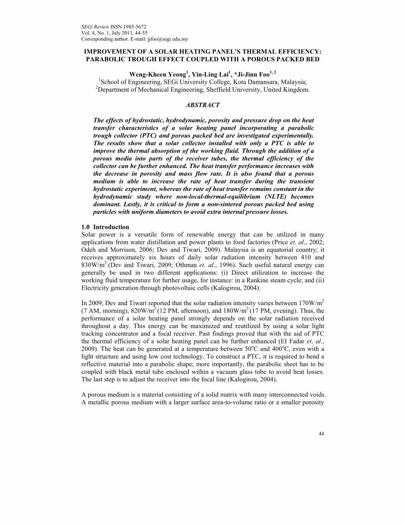
where P is the hydrostatic pressure, h is the measured static head of water, ρ denotes
water density, and g is the gravitational acceleration. All the experiments are carried out
on a sunny day between 11.30AM to 1.00PM.
(a) (b) (c)
Figure 1(a): Schematic Drawing of the Current Solar Heat Panel; (b) Solar Heating
Panel with a PTC installed; and (c) Mild Steel Particles used in the Study
Three different experimental setups are studied in this investigation: (i) A control solar
heating panel without the addition of a PTC and a porous medium; (ii) solar collector with
a PTC installed beneath every pipeline where the aluminum foil is folded onto all the
parabolic surfaces as well as the whole surrounding walls [except the cover glass, see
Figure 1(b)]; and (iii) solar heating panel with the addition of a PTC and a porous medium
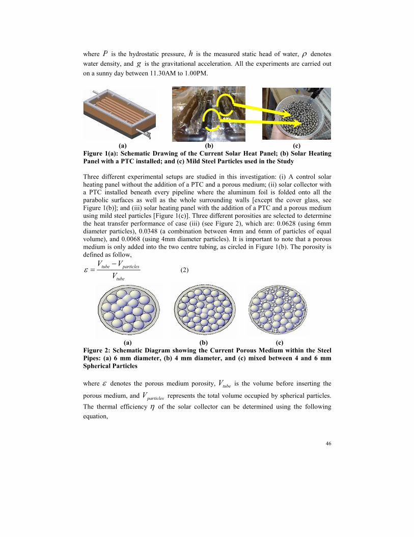
using mild steel particles [Figure 1(c)]. Three different porosities are selected to determine
the heat transfer performance of case (iii) (see Figure 2), which are: 0.0628 (using 6mm
diameter particles), 0.0348 (a combination between 4mm and 6mm of particles of equal
volume), and 0.0068 (using 4mm diameter particles). It is important to note that a porous
medium is only added into the two centre tubing, as circled in Figure 1(b). The porosity is
defined as follow,
tube
particlestube
V
VV −=ε (2)
(a) (b) (c) Figure 2: Schematic Diagram showing the Current Porous Medium within the Steel
Pipes: (a) 6 mm diameter, (b) 4 mm diameter, and (c) mixed between 4 and 6 mm
Spherical Particles
where ε denotes the porous medium porosity, tubeV is the volume before inserting the
porous medium, and particlesV represents the total volume occupied by spherical particles.
The thermal efficiency η of the solar collector can be determined using the following
equation,

47
IA
TTcm inoutp
⋅
−=
)(&η (3)
where m& is the mass flow rate, pc is the specific heat capacity of the working fluid, inT
and outT are the inlet and outlet water temperature, respectively, A is the projected area
of the solar heating panel, and I is the solar radiation intensity of about 820 (W/m2) at
12.00PM. The hydraulic power hP needed to overcome the pressure difference across the
solar heating panel is given defined as follow,
PQPh ∆= (4)
where Q is the volumetric flow rate, and P∆ is the pressure drop across the system.
Thus, by taking into account the heat transfer performance and power consumption, the
overall system efficiency can be determined using the following equation (Rababi and
Mismar, 2003),
IAP
TTcm
h
inoutp
overall⋅+
−=
)(&η (5)
The Reynolds number Re can be expressed as,
Re =µπD
m&4 (6)
where D is the pipe diameter and µ is the viscosity of water. The Reynolds numbers
chosen in the present investigation are 126 and 146, which correspond to the mass flow
rate of 1.38gs-1 and 1.60gs
-1. Lower flow velocities within the laminar flow regime are
preferred in order to ensure a better thermal absorption as the working fluid flow passes
through the system. It is important to note that all the experiments are repeated three times,
with a maximum standard deviation of not more than 0.7oC.
3.0 Results and Discussion The present study aims to improve the solar collector thermal absorption performance by
incorporating a PTC with a porous medium. Five different set of experiments are carried
out, namely: (i) conventional solar heating panel (the control experiment), (ii) solar
collector with a PTC added, and (iii) solar collector coupling between a PTC and a porous
medium with three different porosities ε. In Figure 3, the measured water temperature
distributions under hydrostatic condition are shown. Temperatures are measured at every
10 minutes intervals after direct exposure under the sun (from 11.30AM to 1.00pm).
Clearly the water temperature increases with time of exposure. The water temperature of
the control experiment increases 8.7oC in the first 10 minutes and to 22.8
oC after 60
minutes, the measured temperature distribution is found to slowly reach a plateau of 52oC.
For solar collector with only a PTC installed, it is observed that there is a 14.3oC increase
in temperature at the first time step, and the temperature is still increasing after one hour of

48
observation (to 69oC). Since the whole chamber within the solar collector are fully covered
by reflective aluminum foils, most of the solar energy within the chamber are trapped and
being reflected back to the system. Secondly, the parabolic reflective surfaces are able to
redirect the solar intensity to every steel pipe. Thus, more energy can be absorbed by the
working fluid.
0
10
20
30
40
50
60
70
80
0 10 20 30 40 50 60
Time, t (min)
Measure
d T
em
pera
ture
Dis
trib
ution, T (oC)
Control Experiment
Parabolic Trough
Parabolic Trough + 6 mm Particles
Parabolic Trough + 4 mm Particles
Parabolic Trough + 4/6 mm Particles
Figure 3: Measured Outlet Water Temperature Distributions for Different
Arrangements of Solar Heating Panels performing hydrostatically
Starting from the third experiment, a porous medium is added into the receiver pipes. It is
important to note that only two selected sections of approximately 1.22m in length are fully
occupied by spherical metal particles [see Figure 1(b)]. It is found that the heat transfer
performance increases with the decrease of porosity. Results show that solar collector of
0068.0=ε can greatly enhance the thermal absorption of the system. The outlet water
temperate increases by 40.5% compared with the control experiment, and is 6.5% higher
for the solar collector with only using a PTC, after one hour of direct exposure beneath the
sun.
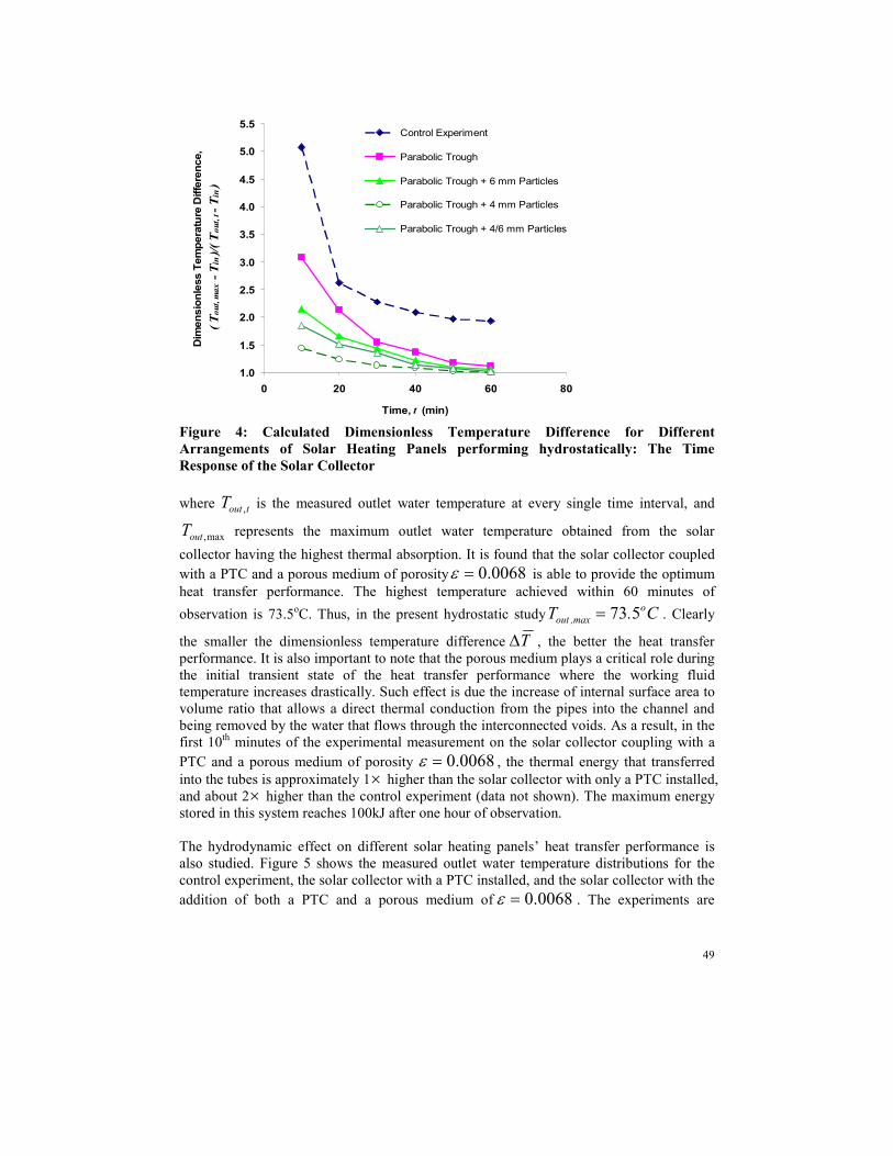
The transient responses of the above hydrostatic solar heating panels heat transfer
performance are shown in Figure 4. The temperature difference is non-dimensionalized as
follows,
intout
inout
TT
TTT
−
−=∆
,
max, (7)
49
1.0
1.5
2.0
2.5
3.0
3.5
4.0
4.5
5.0
5.5
0 20 40 60 80
Time, t (min)
Dim
ensio
nle
ss T
em
pera
ture
Diffe
rence,
( Tout, m
ax - T
in )/( T
out, t - T
in )
Control Experiment
Parabolic Trough
Parabolic Trough + 6 mm Particles
Parabolic Trough + 4 mm Particles
Parabolic Trough + 4/6 mm Particles
Figure 4: Calculated Dimensionless Temperature Difference for Different
Arrangements of Solar Heating Panels performing hydrostatically: The Time
Response of the Solar Collector
where toutT , is the measured outlet water temperature at every single time interval, and
max,outT represents the maximum outlet water temperature obtained from the solar
collector having the highest thermal absorption. It is found that the solar collector coupled
with a PTC and a porous medium of porosity 0068.0=ε is able to provide the optimum
heat transfer performance. The highest temperature achieved within 60 minutes of
observation is 73.5oC. Thus, in the present hydrostatic study C.T o
max,out 573= . Clearly
the smaller the dimensionless temperature difference T∆ , the better the heat transfer
performance. It is also important to note that the porous medium plays a critical role during
the initial transient state of the heat transfer performance where the working fluid
temperature increases drastically. Such effect is due the increase of internal surface area to
volume ratio that allows a direct thermal conduction from the pipes into the channel and
being removed by the water that flows through the interconnected voids. As a result, in the
first 10th minutes of the experimental measurement on the solar collector coupling with a
PTC and a porous medium of porosity 0068.0=ε , the thermal energy that transferred
into the tubes is approximately 1× higher than the solar collector with only a PTC installed,
and about 2× higher than the control experiment (data not shown). The maximum energy
stored in this system reaches 100kJ after one hour of observation.
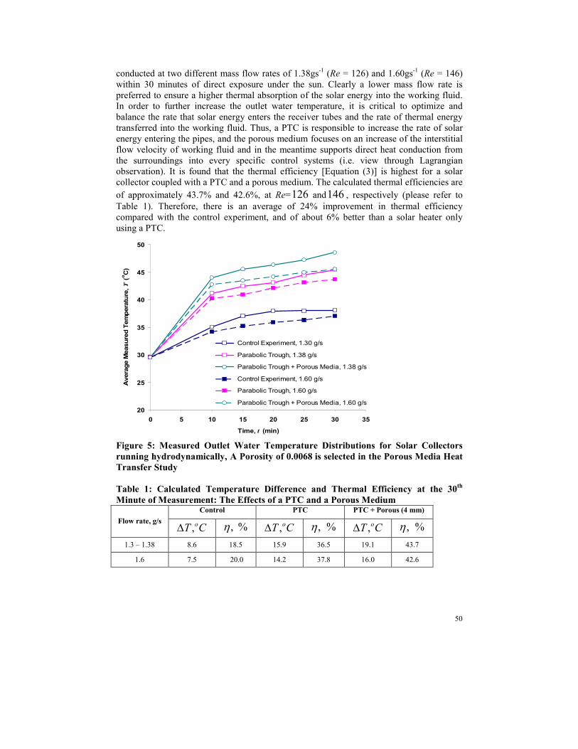
The hydrodynamic effect on different solar heating panels’ heat transfer performance is
also studied. Figure 5 shows the measured outlet water temperature distributions for the
control experiment, the solar collector with a PTC installed, and the solar collector with the
addition of both a PTC and a porous medium of 0068.0=ε . The experiments are
50
conducted at two different mass flow rates of 1.38gs-1 (Re = 126) and 1.60gs
-1 (Re = 146)
within 30 minutes of direct exposure under the sun. Clearly a lower mass flow rate is
preferred to ensure a higher thermal absorption of the solar energy into the working fluid.
In order to further increase the outlet water temperature, it is critical to optimize and
balance the rate that solar energy enters the receiver tubes and the rate of thermal energy
transferred into the working fluid. Thus, a PTC is responsible to increase the rate of solar
energy entering the pipes, and the porous medium focuses on an increase of the interstitial
flow velocity of working fluid and in the meantime supports direct heat conduction from
the surroundings into every specific control systems (i.e. view through Lagrangian
observation). It is found that the thermal efficiency [Equation (3)] is highest for a solar
collector coupled with a PTC and a porous medium. The calculated thermal efficiencies are
of approximately 43.7% and 42.6%, at Re=126 and146 , respectively (please refer to
Table 1). Therefore, there is an average of 24% improvement in thermal efficiency
compared with the control experiment, and of about 6% better than a solar heater only
using a PTC.
20
25
30
35
40
45
50
0 5 10 15 20 25 30 35
Time, t (min)
Avera
ge M
easure
d T
em
pera
ture
, T
(oC
)
Control Experiment, 1.30 g/s
Parabolic Trough, 1.38 g/s
Parabolic Trough + Porous Media, 1.38 g/s
Control Experiment, 1.60 g/s
Parabolic Trough, 1.60 g/s
Parabolic Trough + Porous Media, 1.60 g/s
Figure 5: Measured Outlet Water Temperature Distributions for Solar Collectors
running hydrodynamically, A Porosity of 0.0068 is selected in the Porous Media Heat
Transfer Study
Table 1: Calculated Temperature Difference and Thermal Efficiency at the 30th
Minute of Measurement: The Effects of a PTC and a Porous Medium Control PTC PTC + Porous (4 mm)
Flow rate, g/s CT o,∆ %,η CT o,∆ %,η CT o,∆ %,η
1.3 – 1.38 8.6 18.5 15.9 36.5 19.1 43.7
1.6 7.5 20.0 14.2 37.8 16.0 42.6

51
Table 2: Calculated Temperature Difference and Thermal Efficiency at the 30th
Minute of Measurement: Porosity Effect Control 6 mm Particles 4 mm Particles Mixed 4/6 mm
Flow rate,
g/s CT o,∆ %,η CT o,∆ %,η CT o,∆ %,η CT o,∆
%,η
1.3 – 1.38 8.6 18.5 17.4 39.8 19.1 43.7 18.0 41.3
1.6 7.5 20.0 14.6 38.8 16.0 42.6 15.0 39.9
Figure 6 shows the porosity effect on solar heating panels. The measured outlet water
temperature increases with the decrease of mass flow rate and porosity. In the present study
the Lagrangian energy absorption is rather more important than the observation through an
Eulerian method. Thus, water that runs slower in the system will then have sufficient time
to receive more external solar energy. In all cases, the thermal efficiency for a solar
collector incorporating with a PTC and a porous medium performs better than a solar
collector with only a PTC (thermal efficiency of average 37.2%), which are of average:
39.3% for 0.0628=ε , 40.6% for 0.0348=ε , and 43.2% for 0.0068=ε (see Table
1 and Table 2).
20
25
30
35
40
45
50
0 5 10 15 20 25 30 35
Time, t (min)
Avera
ge M
easure
d T
em
pera
ture
, T
(oC
)
6 mm, 1.38 g/s
4 mm, 1.38 g/s
Mixed 4/6mm, 1.38 g/s
Control experiment, 1.30 g/s
6 mm, 1.60 g/s
4 mm, 1.60 g/s
Mixed 4/6 mm, 1.60 g/s
Control experiment, 1.60 g/s
Figure 6: Measured Outlet Water Temperature Distributions at Different Porosities
and Mass Flow Rates
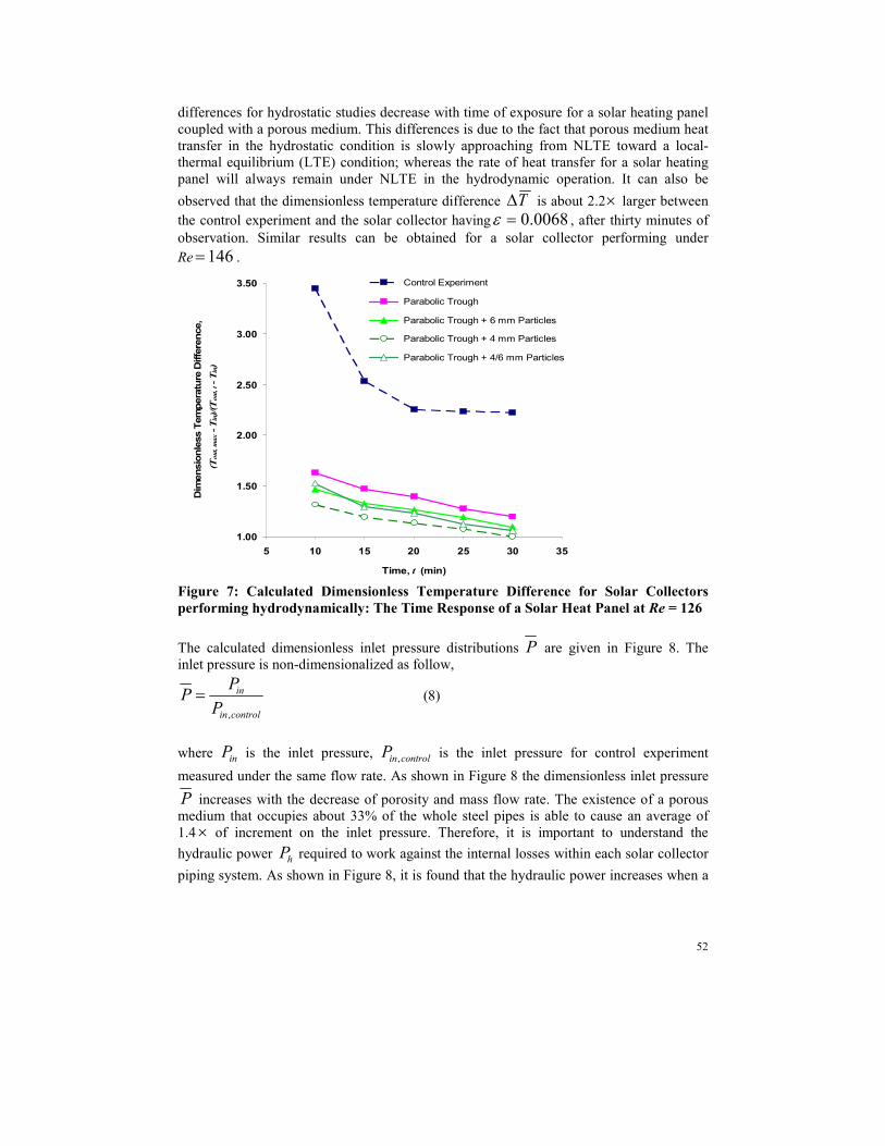
The transient responses of the corresponding hydrodynamic experiments at Re =126 are
shown in Figure 7. It is clear that the smaller the porosity the faster the thermal absorption
to the working fluid. Moreover, it is important to note that the rate of change of the
dimensionless temperature difference T∆ almost remains constant for either using a PTC
alone or coupled with a PTC and a porous medium. These results are different if compared
with the hydrostatic study. The rates of change of the dimensionless temperature
52
differences for hydrostatic studies decrease with time of exposure for a solar heating panel
coupled with a porous medium. This differences is due to the fact that porous medium heat
transfer in the hydrostatic condition is slowly approaching from NLTE toward a local-
thermal equilibrium (LTE) condition; whereas the rate of heat transfer for a solar heating
panel will always remain under NLTE in the hydrodynamic operation. It can also be
observed that the dimensionless temperature difference T∆ is about 2.2× larger between
the control experiment and the solar collector having 0.0068=ε , after thirty minutes of
observation. Similar results can be obtained for a solar collector performing under
Re 146= .
1.00
1.50
2.00
2.50
3.00
3.50
5 10 15 20 25 30 35
Time, t (min)
Dim
ensio
nle
ss T
em
pera
ture
Diffe
rence,
(Tout, m
ax - T
in)/(T
out, t - T
in)
Control Experiment
Parabolic Trough
Parabolic Trough + 6 mm Particles
Parabolic Trough + 4 mm Particles
Parabolic Trough + 4/6 mm Particles
Figure 7: Calculated Dimensionless Temperature Difference for Solar Collectors
performing hydrodynamically: The Time Response of a Solar Heat Panel at Re = 126
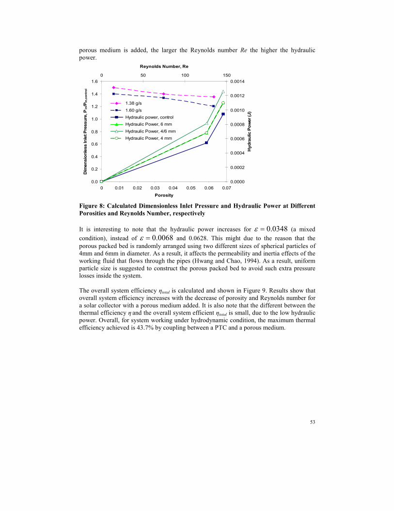
The calculated dimensionless inlet pressure distributions P are given in Figure 8. The
inlet pressure is non-dimensionalized as follow,
controlin
in
P
PP
,
= (8)
where inP is the inlet pressure, controlinP , is the inlet pressure for control experiment
measured under the same flow rate. As shown in Figure 8 the dimensionless inlet pressure
P increases with the decrease of porosity and mass flow rate. The existence of a porous
medium that occupies about 33% of the whole steel pipes is able to cause an average of
1.4 × of increment on the inlet pressure. Therefore, it is important to understand the
hydraulic power hP required to work against the internal losses within each solar collector
piping system. As shown in Figure 8, it is found that the hydraulic power increases when a
53
porous medium is added, the larger the Reynolds number Re the higher the hydraulic
power.
0.0
0.2
0.4
0.6
0.8
1.0
1.2
1.4
1.6
0 0.01 0.02 0.03 0.04 0.05 0.06 0.07
Porosity
Dim
ensio
nle
ss Inle
t Pre
ssure
, P
in/P
in,c
ontr
ol
0.0000
0.0002
0.0004
0.0006
0.0008
0.0010
0.0012
0.0014
0 50 100 150
Reynolds Number, Re
Hydra
ulic P
ow
er (J
)
1.38 g/s
1.60 g/s
Hydraulic power, control
Hydraulic Power, 6 mm
Hydraulic Power, 4/6 mm
Hydraulic Power, 4 mm
Figure 8: Calculated Dimensionless Inlet Pressure and Hydraulic Power at Different
Porosities and Reynolds Number, respectively
It is interesting to note that the hydraulic power increases for 0.0348=ε (a mixed
condition), instead of 0.0068=ε and 0.0628. This might due to the reason that the
porous packed bed is randomly arranged using two different sizes of spherical particles of
4mm and 6mm in diameter. As a result, it affects the permeability and inertia effects of the
working fluid that flows through the pipes (Hwang and Chao, 1994). As a result, uniform
particle size is suggested to construct the porous packed bed to avoid such extra pressure
losses inside the system.
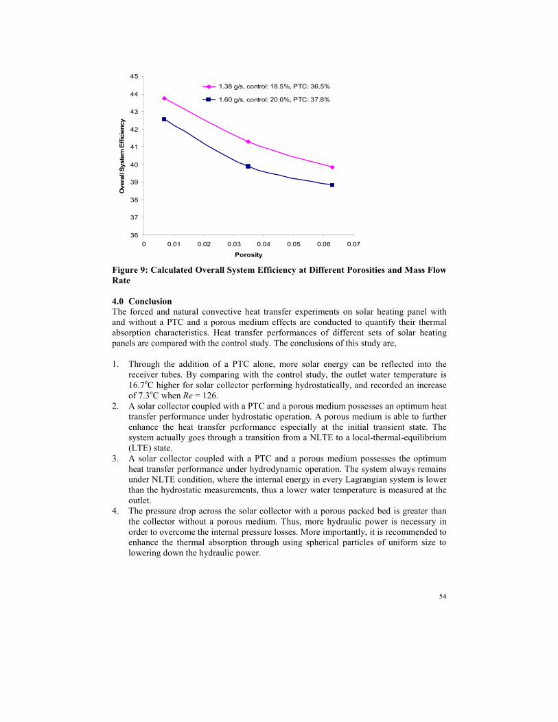
The overall system efficiency ηtotal is calculated and shown in Figure 9. Results show that
overall system efficiency increases with the decrease of porosity and Reynolds number for
a solar collector with a porous medium added. It is also note that the different between the
thermal efficiency η and the overall system efficient ηtotal is small, due to the low hydraulic
power. Overall, for system working under hydrodynamic condition, the maximum thermal
efficiency achieved is 43.7% by coupling between a PTC and a porous medium.
54
36
37
38
39
40
41
42
43
44
45
0 0.01 0.02 0.03 0.04 0.05 0.06 0.07
Porosity
Overa
ll S
yste
m E
ffic
iency
1.38 g/s, control: 18.5%, PTC: 36.5%
1.60 g/s, control: 20.0%, PTC: 37.8%
Figure 9: Calculated Overall System Efficiency at Different Porosities and Mass Flow
Rate
4.0 Conclusion The forced and natural convective heat transfer experiments on solar heating panel with
and without a PTC and a porous medium effects are conducted to quantify their thermal
absorption characteristics. Heat transfer performances of different sets of solar heating
panels are compared with the control study. The conclusions of this study are,
1. Through the addition of a PTC alone, more solar energy can be reflected into the
receiver tubes. By comparing with the control study, the outlet water temperature is
16.7oC higher for solar collector performing hydrostatically, and recorded an increase
of 7.3oC when Re = 126.
2. A solar collector coupled with a PTC and a porous medium possesses an optimum heat
transfer performance under hydrostatic operation. A porous medium is able to further
enhance the heat transfer performance especially at the initial transient state. The
system actually goes through a transition from a NLTE to a local-thermal-equilibrium
(LTE) state.
3. A solar collector coupled with a PTC and a porous medium possesses the optimum
heat transfer performance under hydrodynamic operation. The system always remains
under NLTE condition, where the internal energy in every Lagrangian system is lower
than the hydrostatic measurements, thus a lower water temperature is measured at the
outlet.
4. The pressure drop across the solar collector with a porous packed bed is greater than
the collector without a porous medium. Thus, more hydraulic power is necessary in
order to overcome the internal pressure losses. More importantly, it is recommended to
enhance the thermal absorption through using spherical particles of uniform size to
lowering down the hydraulic power.
55
5. The overall heat transfer performance increases with the decrease in porosity and mass
flow rate, the result reflects itself in the thermal efficiency of the system. The
maximum thermal efficiency of the system reaches 43.7% under hydrodynamic
performance by incorporating a PTC with a porous medium.
5.0 Acknowledgement
The authors would like to thank SEGi University College for financial support of the
current final year research project (SCM-002139).
REFERENCES
A. A. Mohamad, International Journal of Thermal Sciences, 42, 385-395 (2002).
A. EI Fadar, A. Mimet and M. Perez-Garcia, Renewable Energy, 34, 2271-2279 (2009).
G.J. Hwang and C.H. Chao, ASME Journal of Heat Transfer, 116, 456-464 (1994).
H. Price, E. Lüpfert, D. Kearney, E. Zarza, G. Cohen and R. Gee, Journal of Solar Energy
Engineering, 124, 109-125 (2002).
K. R. Kumar and K.S. Reddy, Applied Energy, 86, 1804-1812 (2009).
K. Sopian, M.A. Alghoul, E.M. Alfegi, M.Y. Sulaiman and E.A. Musa, Renewable Energy,
34, 640-645 (2009).
M. Y. H. Othman, B. Yatim and M.H. Ruslan, World Renewable Energy Congress -
Renewable Energy, Energy Efficiency and the Environment, 9, 622-625 (1996).
N. J. Rababi and S.A. Mismar, Solar Energy, 75, 261-268 (2003).
R. Dev and G.N. Tiwari, Desalination, 245, 246-265 (2009).
S. A. Kalogirou, Progress in Energy and Combustion Science, 30, 231-295 (2004).
S. D. Odeh and G.L. Morrison, International Journal of Energy Research, 30, 259-271
(2006).
S. Z. Shuja, B.S. Yibas and M. Kassas, International Journal of Thermal Sciences, 48,
1564-1573 (2009).
W. H. Hsieh and S.F. Lu, International Journal of Heat and Mass Transfer, 43, 3001-3011
(2000).