Embed Size (px)
Citation preview

American Journal of Engineering Research (AJER) 2019
American Journal of Engineering Research (AJER)
e-ISSN: 2320-0847 p-ISSN : 2320-0936
Volume-8, Issue-4, pp-16-27
www.ajer.org Research Paper Open Access
w w w . a j e r . o r g w w w . a j e r . o r g
Page 16
Improvement of 33kv Overcurrent Protection Scheme for
Effurun Transmission Substation at PTI Road, Delta State,
Nigeria
Amakiri O. Friday1, Engr. Prof D.C. Idoniboyeobu2, Engr. Prof C.O. Ahiakwo3,
Engr. Dr S.L. Braide4. 1, 2, 3 & 4 Department of Electrical Engineering, Rivers State University, Port-Harcourt Nigeria
Corresponding Author: Amakiri O. F,
ABSTACT: The research work is initiated to investigate Effurun 3x 60MVA, 132/33kV transmission substation
network, because this network faced fire outbreak, power outage several times, and abnormal tripping of feeder
during last couple of years. Using ETAP software as analytical tool, the network was drawn. The data for each
component in the network was collected from a site visit. The simulator was ruined and different fault scenarios
were created to analyse the existing overcurrent protection schemes and different miss-coordination or
operations results were obtained as a response of protection system to the abnormal conditions. After
studying this network, it was noticed that one of the main reasons for fire outbreak, outage of power and
abnormal tripping of protection devices is the relay setting miss-coordination caused by the use of only definite
minimum time (DMT) and grading by time overcurrent protection scheme. Inverse definite minimum time(IDMT)
relay and grading by both Time current overcurrent protection scheme was chosen, and this scheme is modelled
which starts first by coordinating three phase overcurrent elements, for different paths from furthest
downstream up to the upstream. Next the instantaneous element as a backup protection as applied
successfully. The new relay setting coordination has been applied to all relays in the Effurun substation as a
result from this study. The sequence of operation is well improved and total outage of power, abnormal
tripping of feeders is significantly reduced.
Keywords– definite minimum time (DMT), inverse definite minimum time (IDMT), grading by time, grading by both
time and current, sequence of operation.
----------------------------------------------------------------------------------------------------------------------------- ----------
Date of Submission: 25-03-2019 Date of acceptance: 07-04-2019
----------------------------------------------------------------------------------------------------------------------------- ----------
I. INTRODUCTION
In Nigeria, power systems are made of three divisions that are called a generation, transmission and
distribution and is very complex in nature. Its operations and cost of maintaining is quite high. Hence, there is a
requirement of adequate protection scheme against any fault for strong and reliable operation of power system.
Therefore transmission and distribution feeders should be protected by comprehensive protection scheme [6].
Overcurrent protection schemes for power system has been developed to minimize damage and make sure supply
is safe, continuous and economical. This is achieved by using overcurrent relays. An overcurrent relay is a device
that make measurement or receives signals that causes it to operate and effect the operations of other equipment’s.
It responds to abnormal conditions in faulty section of the network with minimum interruption of supply [1].
Overcurrent relay coordination plays a vital role with overcurrent protection scheme. It is an integral part of the
overall system of overcurrent protection and is absolutely necessary to isolate only the faulty circuit, prevent
tripping of healthy circuit [3]. The overcurrent protection scheme designed for the network should be fast and
selective. For a good protection scheme, a reliable backup should exist in case the primary protective system fails.
[2]. Overcurrent protection scheme designed for the network should be fast and selective. For a good protection
scheme, a reliable backup should exist in case the primary protective system fails. This backup protection should

American Journal of Engineering Research (AJER) 2019
w w w . a j e r . o r g w w w . a j e r . o r g
Page 17
act as a backup either in the same station or in the neighboring lines with a time delay according to the selective
requirement [5]. There should be a backup protection for which proper overcurrent relay setting and coordination
is necessary. To coordinate the overcurrent protection, the backup relay must have enough time delay for the
primary relay (and its breaker) to clear the fault (4).
II. PROBLEMS STATEMENT
There are numerous causes of fire outbreak and electrocution in our electricity transmission and
distribution network in Nigeria, due to faults on our power station feeder’s line, which resulted in shutting down
of socio-economic activities of our society. Therefore a great deal of study and development of devices and design
of overcurrent protection schemes have resulted in continual improvement in the prevention of damage to power
equipment, transmission and distribution lines and to guarantee safety of life and property. Similarly, problems of
inadequate selection of overcurrent protection schemes in our power stations led to system collapse, eventually
the entire system. Without question, the associated problems which has led to:
i. Outage of power supply.
ii. Regular abnormal tripping of the protective devices.
iii. Permanent shorting down of power equipment due to fire outbreak.
iv. Short down of power lines.
III. MATERIALS AND METHODOLOGY
3.1 Materials: A site visit was conducted with Effurun 3x60MVA, 132/33kV Transmission Station P.T.I road
Effurun Delta State. In order to collect the necessary data of the existing network, collect the uploading setting of
the protection system and investigate the defects of the existing setting.
The following data was collected,
i. A one-line diagram of Effurun 3x60MVA, 132/33kV Transmission Substation P.T.I road Effurun Delta State,
Nigeria. Were all the types and rating of the protection devices and their associated current transformers are
shown.
ii. The impedance of all Transmission lines and Transformers.
iii. Load details (MVAR and MW) of the existing network.
iv. Length and type of Transmission lines from Effurun to other station.
The data collected is shown in appendix A and B respectively.
3.2 Methodology:The paper is to investigate Effurun 3x 60MVA, 132/33kV transmission substation network
by using ETAP 16.0.0 software as analytical tools , in other to eliminate problems associated to fire
outbreak, electrocution, regular abnormal tripping of protection devices etc. The simulator was ruined with the
aid of the existing model (DMT) for different scenarios and was discover that one of the main reason for fire
outbreak, abnormal tripping of protection devices and outage of power for Effurun Transmission Substation is the
relay setting miss-coordination caused by the use of only definite minimum time (DMT) with grading by time
overcurrent protection scheme. Base on this Inverse definite Minimum Time(IDMT) relay with grading by both
Time current overcurrent protection scheme was chosen, and this scheme is modelled which starts first by
coordinating the three phase overcurrent elements, for different paths from furthest downstream up to the
upstream. Next the instantaneous element as a backup protection was applied successfully. The new relay
setting coordination to applied to all relays in the Effurun substation as a result from this study.
Figure 1 shows Single line Diagram of Effurun Transmission Substation network,
The station consists of three (3) transformers which have capacity of 60MVA each and has seven (7) feeders,
33kV to Refinery I, 33kV to Refinery ii, 33kV to Warri, 33kV to Sapele, 33KV to P.T.I, 33kV to Effurun, 33kV
to Enerhen. With the purpose of this paper, we are concentrating on the three (3) feeder, Refinery 1 33kV feeder,
Refinery 11 33kV feeder and Enerhen 33kV feeder.

American Journal of Engineering Research (AJER) 2019
w w w . a j e r . o r g w w w . a j e r . o r g
Page 18
Figure 3.1 shows Single line Diagram of Effurun Transmission Substation network
3.3 Simulation Scenarios of the Existing Network of Effurun 3 X 60MVA, 132/33kv Substation Setting.
The existing scheme and setting of this substation all outgoing 33kV lines relay setting was DMT (time grading)
with a time delay of 0.05sec and 0.1 sec with lead to the trip of the outgoing 33kV lines for any fault that occurs
at the substation feeder. Hence the protection is miss-coordinated.
Figure 3.2 Three phase fault on Refinery 1 33kv feeder

American Journal of Engineering Research (AJER) 2019
w w w . a j e r . o r g w w w . a j e r . o r g
Page 19
Figure 3.3 three phase fault for Refinery 11 33kV feeder
Figure 3.4 Three phase fault for Effurun 33kV feeder
3.4 New improved Overcurrent Setting of Effurun Transmission Substation
The coordination started from downstream at 33kV feeders to the upstream at 132kV incomer line, this
coordination carryout by both current and time grading and IDMT relay to ensure adequate fault isolation. The
coordination is shown in the next figures.
3.5 Standard Equation for overcurrent relay
Step 1, read within the existing data excessive and low voltages of the line, short circuit current primary
and secondary current of high voltage current transformer (HV, CT), a primary and secondary current of low
voltage current transformer (LV CT), time graded margin and time setting multiplier (TMS)
Step 2, calculate the relay current of relay 1 (IR1) using equ (3.1)
IR1 =
Fault current
CT ratio
(3.1)

American Journal of Engineering Research (AJER) 2019
w w w . a j e r . o r g w w w . a j e r . o r g
Page 20
Steps 3, Calculate the pickup values of relay 1(PU1) using equation (3.2)
PUI =CS−RCS
100 (3.2)
CS = current setting
RCS =rated current of secondary CT
Steps 4, Calculate the plug setting multiplier (PSM) using equation (3.3)
PSM = IR1
PU1 (3.3)
Steps 5, Determine relay type (t) and calculate the time of operation using the following equation (3.4)
SIR=0.14
PSM0.02 −1 (3.4)
SIR = Standard inverse relay
Steps 6, Calculate the actual operating time (T1) of the relay using equation (3.7)
T1 = t x TMS (3.6)
Steps 7, Calculate fault current (IFR2) in relay 2 using equation (3.8)
TFR2 =Fault current LV
HV (3.7)
Steps 8, Calculate fault current (IR2) in relay 2 using equation (3.9)
IR2 = IFR2
Relay2 CT ratio (3.8)
Steps 9, Calculate pickup current of relay 2 (PU2) using equation (3.10)
PU2 = CS − RCS
100 (3.9)
Steps 10, Calculate the plug setting multiplier of relay 2 (PSM2) using equation (3.11)
PSM = IR2
PU2 (3.10)
Steps 11, Determine the time of operation using step 4
Steps 12, Calculate the actual operating time of relay 2 (T2) using equation (3.12)
T2 = t x TMS + T2 (3.11)
3.6 Simulation Scenarios (New Setting)
Now when applying the new setting mentioned in above section in ETAP to simulate the sequence of
operations for the same type of faults as mention in the existing case, the results showed that all the problems
associated with the existing setting has been resolved and the network is well coordinated.
Figure 3.5 Three phase fault on Refinery 1 33kV feeder (New case)

American Journal of Engineering Research (AJER) 2019
w w w . a j e r . o r g w w w . a j e r . o r g
Page 21
Figure 3.6 Three phase fault was simulated at Refinery 11 33kV feeder (New case)
Figure 3.7 Three phase fault was simulated at Effurun 33kV feeder (New case)
IV. RESULT AND DISSCUSSION 4.1 Result Summary and Discussion of the existing case for Refinery 1 33kV feeder
The sequence of operation (tripping) that occurred due to the insertion of fault on Refinery 1 33kV feeder

American Journal of Engineering Research (AJER) 2019
w w w . a j e r . o r g w w w . a j e r . o r g
Page 22
(Figure 2) are summarized in Table 4.1.
Table 4.1 Sequence of operation for Refinery 1 33kV feeder
From table 4.1, it’s clear that the feeder relay (relay 11) tripped before the faulted relay 13 and relays
at the primary side of the transformers (relays 3) tripped at 250milliseconds , which means that for a single three
phase fault at the downstream feeder will trip other downstream feeders.
The correct sequence of operation is that the feeder relay(relay 13) must first trip, followed by the
secondary side of the transformer relay (relay 6) which is delayed by at least 150 millisecond after which the
primary side of the transformer 132kV incomers (relay 3) will also be delayed by at least 150 millisecond before
it trips.
4.2 Result Summary and Discussion of the existing case for Refinery 11 33kV feeder
The sequence of operation (tripping) that occurred due to the insertion of fault on Refinery 11 33kV feeder
(Figure 3.3) are summarized in Tables 4.2.
Table 4.2 Sequence of operation for Refinery 11 33kV feeder
From table 4.2, it’s clear that the feeder relay (relay 11) tripped before the faulted relay (relay 12) and
relays (relays 13) tripped at the same time , which means that the whole T23 incomer line is out for a single three
phase fault at the downstream feeder.
The correct sequence of operation is that the feeder relay(relay 12) must first trip followed by the
secondary side of the transformer relay (relay 6) delayed by at least 150 millisecond then the primary side of the
transformer 132kV incomers (relay 3) also delayed by at least 150 millisecond.
4.3 Result Summary and Discussion of the existing case for Effurun 33kV Feeder
The sequence of operation (tripping) that occurred due to the insertion of fault on Effurun 33kV Feeder
(Figure 3.4) are summarized in Table 4.3.

American Journal of Engineering Research (AJER) 2019
w w w . a j e r . o r g w w w . a j e r . o r g
Page 23
Table 4.3 Sequence of operation for Effurun 33kV feeder
From table 4.3, it’s clear that the faulted feeder relay (relay 11) tripped before the adjacent relay (relay
12) and relays (relays 13) tripped at the same time , which means that for a single three phase fault at the
downstream feeder will not affect the upstream T23 incomer line.
Another point on this analysis is that the feeder relay (relay 11 & 13) time overcurrent (TOC) is blocked
by instantaneous overcurrent for its operation. Therefore the protection scheme is miss-coordinated.
The correct sequence of operation is that the feeder relay(relay 11) must first trip, followed by the secondary side
of the transformer relay (relay 6) delayed by at least 150 millisecond then the primary side of the transformer
132kV incomers (relay 3) also delayed by at least 150 millisecond.
4.4 Result Summary and Discussion of the new case for Refinery 1 33kV feeder
The results obtained from the new relay coordination setting is shown in append C (Table C.2) The tripping that
occurred due to the insertion of fault on Refinery 1 33kV feeder are (figure 3.5) summarized in Table 4.4.
Table 4.4 Sequence of operation for a three phase fault on Refinery 1 33kV feeder (New case)
From table 4.4. It is clear that the feeder relay (relay 13) was tripped first at 0ms by instantaneous element
followed by the incomer secondary relay (relay 6) delayed after 215 millisecond then the primary side of the
transformer relay (relay 3) tripped after 382millisecond. Now this is the correct sequence of operation, also the
grading margin between relays is maintained above 150 millisecond. Hence, miss-coordination will not occur as
demonstrated in figure (3.5)
From above sequence of operation, the discrimination was conducted correctly which was not achieved at the
existing setting as shown in figure (2).

American Journal of Engineering Research (AJER) 2019
w w w . a j e r . o r g w w w . a j e r . o r g
Page 24
4.5 Result Summary and Discussion of the new case for Refinery 11 33kV feeder
The results obtained from the new relay coordination setting is shown in append C (Table C.2) The
tripping that occurred due to the insertion of fault on Refinery 11 33kV feeder (figure3. 6) are summarized in
Table 4.5.
Table 4.5Sequence of operation for a three phase fault on Refinery 11 33kV feeder (New case)
From table 4.5 It is clear that the faulted feeder relay (relay 12) was tripped first at 100ms by
instantaneous element followed by the incomer secondary relay (relay 6) delayed after 250 millisecond then the
primary side of the transformer relay (relay 3) tripped. Now this is the correct sequence of operation, also the
grading margin between relays is maintained above 150 millisecond. Hence, miss-coordination will not occur as
demonstrated in figure (3.6).
From above sequence of operation, the discrimination was conducted correctly which was not achieved at the
existing setting as shown in figure (3.3).
4.6 Result Summary and Discussion of the new case for Effurun 33kV feeder
The results obtained from the existing relay coordination setting is shown in appendices C (Table C.2).
The tripping that occurred due to the insertion of fault on Effurun 33kV feeder (figure 3.7) are summarized in
Tables 4.6
Table 4.6 Sequence of operation for a three phase fault on Effurun 33kV feeder (New case)
Comparing table 4.6 with that of chapter three (figure 3.4), it’s clear that the correct sequence of operation
is now achieved. Also the grading margin between relays is maintained above 150 millisecond.

American Journal of Engineering Research (AJER) 2019
w w w . a j e r . o r g w w w . a j e r . o r g
Page 25
From the above sequence of operation analysis, shows the benefits of using instantaneous current at the beginning
of the faulted feeder line to isolate the faults on the line as quickly as possible. In this case, the instantaneous
element enable relay 12 to trip the line at 0 milliseconds.
V. CONCLUSION 5.1 Conclusion
The overcurrent protection settings coordination has been achieved successfully, and the sequence
of tripping starts at far downstream of the three (3) 33kV feeder relay with IDMT, then followed by the upstream
of 33kV incomer relay and 132kV primary transformer relay. Furthermore, the pickup settings for overcurrent
element were coordinated as main protection and instantaneous element was performed successfully as a back-up
protection.
REFERENCES [1]. Chebbi S, & Meddeb A. (2015). Protection plan medium voltage distribution network in Tunisia. International scholarly and scientific
Research & Innovation. 9(2), 1307- 6892. [2]. Jayaprakash J, .Mercy P.A, Jothi L, & Juanola P. (2016). Planning and Coordination of Relay in Distribution system using E-TAP
.Pakistan Journal of Biotechnology. 13(special issue on Innovation in information embedded and communication system), 252-256
92016. [3]. Linus O.I, Awosope C.D.A, & Ademola A. (2013). A review of PHCN Protection Schemes, International journals of Engineering
Research & Technology (IJERT), 5(8), 2278-8181.
[4]. Mazen A.S, Ahamed A.R.K, & Mohamed H. (2015). Improvement of protection coordination for a distribution system connected to a micro grid using unidirectional fault current limiter. Ain shames Engineering Journal, 5(2) 1-10, http; // doi; 10./016/jasej.
[5]. Usman I.A, (2015). A design of protection schemes for AC Transmission lines considering a case study; International Journal of
Electrical and Electronics Engineers, 7(2), 2286-6197. [6]. Stanley .H, H, & Arun G.P (2008). Power system relaying, 3rd Edition, England John Wiley & son limited and research study press
limited.
Tables
Table A.1 Transformer Technical Data
Sta
tion
Tra
nsf
orm
er
Sta
tion
MV
A
Pri
mar
y
Vo
lt
(KV
)
Sec
ond
ary
Vo
lt
(KV
)
Vec
tor
Gro
up
Copp
er L
oss
KV
Iro
n L
oss
KV
Lea
kag
e
imped
ance
Xp
/s%
X/R
R
atio
Ear
th
Gro
un
din
g
HV
sid
e Z
p
Ear
th
Gro
un
din
g
LV
sid
e Z
s
T21
Transformer
60 132 33 YNd11 48.315 9.804 7.7 15.906 Reactor -
T22
Transforme
r
60 132 33 YNd11 X X X X Reactor -
T23
Transforme
r
60 132 33 YNd11 48.315 9.804 7.7 15.906 Reactor -
Source: Benin Electricity Distribution Company (BEDC), Effurun 3 x 132/33kV Substation.
American Journal of Engineering Research (AJER) 2019
w w w . a j e r . o r g w w w . a j e r . o r g
Page 26
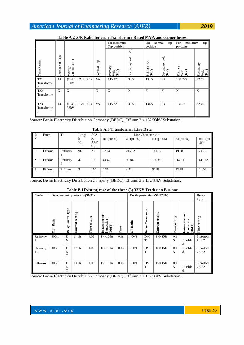
Table A.2 X/R Ratio for each Transformer Rated MVA and copper losses T
ran
sfo
rmer
Nu
mber
of
Tap
s
Vo
ltag
e
Co
mb
inat
ion
No
rmal
Tap
For maximum
Tap position
For normal tap
position
For minimum tap
position
Pri
mar
y
Vo
lt
(KV
)
Sec
ond
ary
vo
lt (
KV
)
Pri
mar
y v
olt
(KV
)
Sec
ond
ary
volt
(KV
)
Pri
mar
y
Vo
lt
(KV
)
Sec
ond
ary
Vo
lt
(KV
)
T21
Transformer
14 (134.5 ±2 ± 7.5)
33kV
9A 145.225 36.55 134.5 33 130.775 32.45
T22
Transforme
r
X X X X X X X X X
T23
Transforme
r
14 (134.5 ± 2± 7.5)
33kV
9A 145.225 33.55 134.5 33 130.77 32.45
Source: Benin Electricity Distribution Company (BEDC), Effurun 3 x 132/33kV Substation.
Table A.3 Transformer Line Data
S/N
From To Length
Km
ACSR/
AAC
Sqm
Line Characteristic
R1 (pu: %) XI (pu :%) Ro (pu :%) BI (pu :%) Bo (pu :%)
1 Effurun Refinery
1
96 250 67.64 216.82 181.37 49.28 29.76
2 Effurun Refinery
2
42 150 49.42 98.84 110.89 662.16 441.12
3 Effurun Effurun 2 150 2.35 4.71 52.80 32.48 21.01
Source: Benin Electricity Distribution Company (BEDC), Effurun 3 x 132/33kV Substation.
Table B.1Existing case of the three (3) 33KV Feeder on Bus bar
Feeder Overcurrent protection(50/51) Earth protection (50N/51N) Relay
Type
CT
R
ati
o
Dela
y C
urve
typ
e
Cu
rren
t se
ttin
g
Tim
e s
ett
ing
Inst
an
tan
eou
s
Pro
tecti
on
(DM
T)
Tim
e
CT
Ra
tio
Dela
y C
urve t
yp
e
Cu
rren
t se
ttin
g
Tim
e s
ett
ing
Inst
an
tan
eou
s
Pro
tecti
on
(DM
T)
Tim
e s
ett
ing
Refinery
1
400/1 DM
T
1>1In 0.05 1>>10 In 0.1s 400/1 DMT
1>0.15Ie 0.15
Disable
d
Siprotech 7SJ62
Refinery
11
800/1 DM
T
1>1In 0.05 1>>10 In 0.1s 800/1 DMT
1>0.15Ie 0.15
Disabled
Siprotech 7SJ62
Effurun 800/1 D
NT
1>1In 0.05 1>>10 In 0.1s 800/1 DM
T
1>0.15Ie 0.1
5
Disabled
Siprotech
7SJ62
Source: Benin Electricity Distribution Company (BEDC), Effurun 3 x 132/33kV Substation.

American Journal of Engineering Research (AJER) 2019
w w w . a j e r . o r g w w w . a j e r . o r g
Page 27
Table B.2Existing Setting of 33KV Transformer Incomer Line
Feeder Overcurrent protection(50/51) Earth protection (50N/51N)
CT
Ra
tio
Dela
y C
urve
typ
e
Cu
rren
t
Sett
ing
Tim
e s
ett
ing
Inst
an
tan
eou
s
Pro
tecti
on
(DM
T)
Tim
e
CT
Ra
tio
Dela
y C
urve t
yp
e
Cu
rren
t se
ttin
g
Tim
e s
ett
ing
Inst
an
tan
eou
s
Pro
tecti
on
(DM
T)
Tim
e s
ett
ing
Rela
y
Ty
pe
T21 Transfor
mer
1200/1 DMT
1>1In 0.25s 10
0.1s
600/1
DM
T
1>0.2Ie
0.05 Disabled
Siprotech 7SJ62
T22
Transfor
mer
X X X X
10
0.1s X X X X Siprotec
h 7SJ62
T23
Transformer
1200/1 DM
T
1>1In 0.25s
10
0.1s 300/
1
D
MT
1>0.
2Ie
0.05
Source: Benin Electricity Distribution Company (BEDC), Effurun 3 x 132/33kV Substation.
Table C.3Existing Setting of 132KV Transformer Feeders
Feeder Overcurrent protection(50/51) Earth protection (50N/51N) Relay
Type
CT
Ra
tio
Dela
y C
urve T
yp
e
Cu
rren
t S
ett
ing
s
Tim
e s
ett
ing
Inst
an
tan
eou
s
Pro
tecti
on
ID
MT
Tim
e
CT
Ra
tio
Dela
y C
urve t
yp
e
Cu
rren
t se
ttin
g
Tim
e s
ett
ing
Inst
an
tan
eou
s
Pro
tecti
on
ID
MT
Tim
e s
ett
ing
T21
Transformer
300/
1
DM
T
1>1 In 0.25s 10
0.2s
300/1 D
MT
1>0.2I
e
0.05 Disabled
Siprotec
h 7SJ62
T22
Transformer
X X X X X
X X X X X Siprotec
h 7SJ62
T23
Transfor
mer
300/
1
DM
T
1>1 In 0.25s 10 0.22 300/1 D
M
T
1>0.2I
e
0.05 Siprotec
h 7SJ62
Source: Benin Electricity Distribution Company (BEDC), Effurun 3 x 132/33kV Substation
Table C.1 New Relay Setting on the three (3) 33kV Feeder Lines
Feeder Overcurrent protection(50/51) Earth protection (50N/51N) Relay
Type
CT
R
ati
o
Dela
y C
urve
typ
e
Cu
rren
t se
ttin
g
Tim
e s
ett
ing
Inst
an
tan
eou
s
Pro
tecti
on
ID
MT
Tim
e
CT
Ra
tio
Dela
y C
urve t
yp
e
Cu
rren
t se
ttin
g
Tim
e s
ett
ing
Inst
an
tan
eou
s
Pro
tecti
on
ID
MT
Tim
e s
ett
ing
Refinery
1
400/
1
ID
M
T
1>
1In
0.2 1>>10In 0s 400/1 ID
M
T
1>0.15I
e
0.15 Disabled Siprot
ech
7SJ801
Refinery
11
800/
1
ID
MT
1>
1In
0.05 1>>5In 0s 800/1 ID
MT
1>0.15I
e
0.15 Disabled Siprot
ech 7SJ62
Effurun
800/
1
1D
NT
1> 1 0.25 1>>8In 0s 800/1 ID
MT
1>0.15I
e
0.15 Disabled Siprot
ech 7SJ62

American Journal of Engineering Research (AJER) 2019
w w w . a j e r . o r g w w w . a j e r . o r g
Page 28
Table C.2 New Relay Setting on the 33kV Transformer Secondary
Feeder Overcurrent protection(50/51) Earth protection (50N/51N) Relay
Type
CT
Ra
tio
Dela
y C
urve T
yp
e
Cu
rren
t S
ett
ing
s
Tim
e s
ett
ing
Inst
an
tan
eou
s
Pro
tecti
on
ID
MT
Tim
e
CT
Ra
tio
Dela
y C
urve t
yp
e
Cu
rren
t se
ttin
g
Tim
e s
ett
ing
Inst
an
tan
eou
s
Pro
tecti
on
ID
MT
Tim
e s
ett
ing
T21 Transfor
mer
Secondary
1200/1 IDMT 1>1.2In
0.05s 8
0.1s
600/1 IDM
T
1>0.2
Ie
0.05 Disabled
Siprotech
7SJ62
T22
Transformer
X X X X X
X X X X X Siprot
ech 7SJ62
T23
Transformer
1200/1 IDMT 1>1.2
In
0.25s 10 0.2 600/1 ID
M
T
1>
0.2
Ie
0.05 Siprot
ech
7SJ62
Amakiri O. F," Improvement of 33kV Overcurrent Protection Scheme for Effurun Transmission
Substation at PTI Road, Delta State, Nigeria" American Journal of Engineering Research (AJER),
vol.8, no.04, 2019, pp.16-27