Embed Size (px)
Citation preview
Burns Cooley Dennis, Inc.Geotechnical, Pavements and Materials Consultants
Burns Cooley Dennis, Inc.Geotechnical, Pavements and Materials Consultants
IMPROVED POROUS FRICTION COURSES (PFC) ONASPHALT AIRFIELD PAVEMENTS
Volume II: Summary of Research
for
AAPTP PROJECT 04-06
Submitted to
Airfield Asphalt Pavement Technology Program
By
Burns Cooley Dennis, Inc.551 Sunnybrook Road
Ridgeland, Mississippi 39157
ACKNOWLEDGMENT OF SPONSORSHIP
This report has been prepared for Auburn University under the Airport Asphalt Pavement TechnologyProgram (AAPTP). Funding is provided by the Federal aviation Administration (FAA) underCooperative Agreement Number 04-G-038. Dr. David Brill is the Technical manager of the FAA AirportTechnology R&D branch and the Technical manager of the Cooperative Agreement. Mr. Monte Symonsserved as the Project Director for this project. The AAPTP and the FAA thank the Project TechnicalPanel that willingly gave of their expertise and time for the development of this report. They wereresponsible for the oversight and the technical direction. The names of those individuals on the ProjectTechnical Panel follow:
1. Ryan King2. Gary G. Harvey3. John Cook
DISCLAIMERThe contents of this report reflect the views of the authors, who are responsible for the facts and theaccuracy of the data presented within. The contents do not necessarily reflect the official views andpolices of the Federal Aviation Administration. The report does not constitute a standard, specification orregulation.
July 2007
ii
IMPROVED POROUS FRICTION COURSES (PFC) ON ASPHALTAIRFIELD PAVEMENTS
Draft Final Report
for
AAPTP Project 04-06
Submitted to
Airfield Asphalt Pavement Technology Program
By
L. Allen Cooley, Jr., Ph.D.Senior Materials/Pavements Engineer
Burns Cooley Dennis, Inc.551 Sunnybrook Road
Ridgeland, Mississippi 39157
R. C. AhlrichPrincipal
Burns Cooley Dennis, Inc.551 Sunnybrook Road
Ridgeland, Mississippi 39157
Donald E. WatsonResearch Engineer
National Center for Asphalt Technology277 Technology ParkwayAuburn, Alabama 36830
P. S. Kandhal, P.E.Associate Director Emeritus
National Center for Asphalt Technology277 Technology ParkwayAuburn, Alabama 36830
July 2007
iii
Table of ContentsList of Figures ................................................................................................................................ ivList of Tables .................................................................................................................................. vINTRODUCTION .......................................................................................................................... 1
Objectives ................................................................................................................................. 1Report Purpose and Organization ............................................................................................. 2
ADVANTAGES AND DISADVANTAGES OF PFCS ON AIRFIELD PAVEMENTS ............. 2MIX DESIGN FOR PFC USED ON AIRFIELD PAVEMENTS.................................................. 3PRODUCTION AND CONSTRUCTION OF PFC MIXES FOR AIRFIELD PAVEMENTS .. 11MAINTENANCE OF PFC AIRFIELD PAVEMENTS............................................................... 17CONCLUSIONS AND RECOMMENDATIONS ....................................................................... 20
Conclusions............................................................................................................................. 20Recommendations................................................................................................................... 21
Potential Improvements .................................................................................................... 22Recommendations and Future Research........................................................................... 23
REFERENCES ............................................................................................................................. 23
iv
List of Figures
Figure 1: Effect Of Fiber on Draindown Potential (10).................................................................. 7Figure 2: Effect of Asphalt Binder Type on Cantabro Abrasion Loss (10).................................... 7Figure 3: Recommended Gradation Band for ¾ in. Maximum Aggregate Size PFC .................... 9Figure 4: Recommended Gradation Band for ½ in. Maximum Aggregate Size PFC .................... 9Figure 5: Vertical Asphalt Binder Storage Tanks (Courtesy Heatec, Inc.) .................................. 13Figure 6: Fiber Pugmill-Type Dispersion System ....................................................................... 14Figure 7: Fiber Injection Point in a Drier-Drum Plant.................................................................. 14

v
List of Tables
Table 1: Coarse Aggregate Quality Requirements for PFC............................................................ 5Table 2: Fine Aggregate Quality Requirements for PFC................................................................ 5Table 3: Recommended PFC Gradation Bands ........................................................................... 10
1
Summary of Research
INTRODUCTION
The term porous friction course (PFC) in the US is used to describe an HMA having anopen aggregate grading that is used as a wearing course. Porous friction courses have been usedwithin the US since the 1930’s. When placed as a wearing surface, these mixes have proven aneffective method for improving the frictional characteristics of pavements, especially in wetweather. Porous friction courses improve wet weather skid resistance because of the openaggregate grading. This open gradation results in a significant amount of macrotexture at thepavement surface. Additionally, the open gradation with minimal fines results in water beingable to infiltrate into the PFC layer and flow laterally through the PFC layer to the pavementedge. Without the water on the pavement surface, hydroplaning potential is greatly reduced.
Even though PFCs have been around many, many years, the performance of these mixtypes has been mixed. There have been reports of rapid and catastrophic occurrences of ravelingwithin PFC layers. Any raveling that occurs will result in potential foreign object damage(FOD). Also, there have been reports of PFC wearing surfaces tearing at locations where highspeed turns or locked wheel turns take place.
Because of the safety benefits associated with PFCs, the highway industry has conducteda significant amount of research on these mixes over the last 10 to 15 years. In comparison tothe highway industry, little work on the use of PFCs for airfield pavements has been conductedin the last 10 to 15 years. Therefore, there is a need to evaluate the current state of practice onthe use of PFCs. Information obtained should be used to provide guidance for the use of PFCson airfields and to identify potential improvements for using PFC wearing layers.
Objectives
The objective of this study was to develop technical guidance and direction to improvethe performance of PFC mixtures on airfield pavements. This guidance was to consider but notbe limited to the following:
1) Performance history of PFC on airfield pavements;2) PFC mix design requirements and qualities and characteristics of
component materials;3) Construction requirements and limitations;4) Effect of temperatures and other climatic conditions, especially durability under
freeze-thaw conditions, on construction and performance of PFC;5) Existing surface preparation requirements;6) Skid resistance characteristics of PFC;7) Service life and maintenance of PFC;8) Airfield pavement maintenance, including removal of aircraft tire rubber from the
pavement surface;9) Performance of PFC considering airfield classifications and type of
aircraft using the facility; and
2
10) Compare and contrast design and performance of PFC use on highways andairfields.
Report Purpose and Organization
The Final Report for AAPTP 04-06 is divided into two volumes. Volume I of the FinalReport provides documentation of all research results. Detailed discussions are provided on theadvantages/disadvantages of using PFCs on airfield pavements, design of PFC mixes for airfieldapplications, production and construction of PFC mixes and maintenance of PFC pavementlayers. Also, included within this Volume I of the Final Report are conclusions andrecommendations for the use of PFC mixes on airfield pavements. For each of the conclusionsand recommendations detailed, discussions are provided for justification. Because the end userfor the research results will be practicing engineers, Volume II was developed to provide aconcise summary of the best practices developed during the conduct of this research study.
This volume of the Final Report is divided into five primary sections. The first sectionsummarizes the advantages and disadvantages of using PFCs for airfield pavements. The secondsection provides a summary of the mix design procedure recommended as part of the study.Also included are discussions on the desirable properties of PFC mixes and how they are relatedto mix design. These desirable properties were used to develop the recommended mix designmethod. The third and fourth sections discuss current practices for production/construction ofPFC mixes. Finally, the conclusions and recommendations from this research project areprovided.
ADVANTAGES AND DISADVANTAGES OF PFCS ON AIRFIELD PAVEMENTS
The advantages and disadvantages of using PFCs are both primarily related to theopenness of these mixes. The open nature of PFCs allows water to infiltrate into the layer. Sincethe water infiltrates into the layer, water films will not develop on the pavement surface. Waterfilms on the pavement surface increase the potential for hydroplaning. Hydroplaning can makeaircraft lose directional control and the ability to brake.
Because of the open gradation inherent in PFCs, these mix types yield a significantamount of surface texture on the pavement surface in the wave length and amplitude range ofmacrotexture. High levels of macrotexture combined with the selection of polish resistantaggregates (to provide microtexture) result in improved frictional properties compared to typicaldense-graded HMA layers, especially in wet weather.
A benefit that is not specifically related to the ability of PFCs to remove water from thepavement surface is the improved smoothness compared to typical HMA mixes. The improvedsmoothness is likely related to the constructability of PFC mixes. The goal of PFC compactionis simply to seat the aggregates, not densify the mix to an impermeable compaction level. At thetypical high speeds encountered on airfield runways, the improved smoothness will reduce thepotential for aircraft structural damage and component fatigue; reduce the potential for aircraftprematurely becoming airborne; improve the contact between tires and the pavement surface;minimize aircraft vibrations; and provide a more comfortable ride for passengers(2).
3
The primary disadvantages of using PFC layers are winter maintenance, potential rapidraveling of the layer, and moisture damage in underlying layers. Because of the open nature ofPFCs, these layers have different thermal properties than typical dense-graded HMA layers.Porous friction course layers will generally reach a freezing temperature prior to dense-gradedmixes and stay at a freezing temperature longer. For this reason, PFC layers generally require adifferent winter maintenance regime than other pavement surface types.
The primary distress that has been associated with the use of PFCs is raveling. Withinthe highway industry the occurrence and severity of raveling caused a moratorium by someagencies on the use of PFCs within the 1980’s. During the interviews with various airfieldpavement engineers, raveling was also identified as a problem with some PFC layers. Ravelingof any kind increases the potential for FOD.
Another potential problem identified in several of the airfield pavement engineerinterviews was stripping in underlying layers. Stripping in underlying layers has also been notedin highway uses. It is unlikely that changes can be made to the design and construction of PFCmixes to minimize the potential for stripping in underlying layers; however, modifications canlikely be made to the design and construction of underlying layers to minimize the potential forstripping.
During the life of PFC layers, dirt, debris, winter maintenance products and othermaterials can enter the void structure. These contaminants will lead to clogging of the layer andresults in the layer not being able to remove water from the pavement surface. It should bestated; however, the clogged PFCs still maintain their frictional properties because of the highamount of macrotexture. Another potential problem with debris within the voids of the PFClayers is that the debris can retain moisture after the rain event leading to an increased potentialfor moisture damage.
MIX DESIGN FOR PFC USED ON AIRFIELD PAVEMENTS
In order to make recommendations for improving the design of PFC mixes for airfields,some discussion is needed to describe the desirable properties for PFC pavement layers.According to AC 150/5320-12C, Measurement, Construction, and Maintenance of Skid-Resistant Airport Pavement Surfaces, PFC pavements are one method for improving runwaypavement skid resistance and mitigating hydroplaning. Therefore, the desirable properties of aPFC for airfield applications are a wearing layer that provides high frictional resistance andminimizes the potential for hydroplaning, without increasing the potential for FOD. Since somelarger aircraft will operate on the PFC, the mixture should also have sufficient shear strength toresist any permanent deformation or gouging (due to locked-wheel turning or braking traffic).One of the perceived disadvantages of PFCs is the occurrence of raveling; therefore, PFCs,should also be durable with minimal potential for raveling.
Improved frictional properties can be achieved by focusing on two characteristics of PFCmixtures. First, an open-grading is needed within the aggregate gradation so that the PFC willhave a significant amount of macrotexture. Macrotexture is directly related to the shape, size,angularity, density, distribution and arrangement of aggregates within the pavement surface (1).
4
The second characteristic is proper selection of aggregates. Aggregates with a significantamount of microtexture that are not susceptible to polishing should be selected.
Hydroplaning occurs when a layer of water builds up between a tire and the pavementsurface breaking the contact between the tire and pavement surface (2) and can be combated inone of two ways. The first method is to remove water from the pavement surface such that thereis no layer of water that can break the contact between the tire and pavement surface. This canbe easily accomplished using PFCs as these mixes are generally designed to have a highpercentage of air voids. The high percentage of air voids within a PFC layer increases thepotential for these air voids to become interconnected. Interconnected air voids providepathways for water to infiltrate into the PFC layer. Water that infiltrates into a PFC is notavailable for creating a water layer to allow a break in contact between tires and the pavementsurface. However, the water that infiltrates into the OGFC layer must be transported to thepavement edge and discharged from the layer. The second method of mitigating hydroplaning isto provide a significant amount of macrotexture within the pavement surface (5). Significantmacrotexture provides channels at the pavement surface for water pooled on the surface to bedisplaced due to the pressure created by aircraft tires passing over the pavement surface.
Another characteristic that is important to PFC layers is that the mixture should haveenough shear strength to resist the actions of turning or braking aircraft. As larger aircraft turn orbrake, very large shear stresses are developed between the tire and pavement surface. If theshear stresses created are larger than the shear strength, particles will become dislodged creatingFOD. Therefore, high shear strengths are needed for PFC mixtures.
The final characteristic that is important for PFC is durability. Many of interviewsconducted with the airfield pavement engineers cited raveling as a problem with PFCs.Therefore, any potential improvements should attempt to make PFCs more durable.
The potential areas for improvements in mix design and divided by the four steps indesigning PFCs: materials selection, selection of design gradation; selection of optimum asphaltbinder content and evaluation of moisture susceptibility. The following paragraphs describepotential improvements for the design of porous friction courses.
Materials needing selection include coarse aggregates, fine aggregates, mineral fillers,asphalt binders and additives. Porous friction courses can be considered a specialty type HMAbecause they contain an open aggregate grading having a large percentage of coarse aggregateand a low percentage of fine aggregate and minimal mineral filler. Therefore, the performanceof PFCs is directly related to the characteristics of the aggregates, especially coarse aggregates.Because of the open aggregate grading, the coarse aggregates tend to be in contact with eachother within the layer. This contact of the aggregates is generally termed stone-on-stone contact.
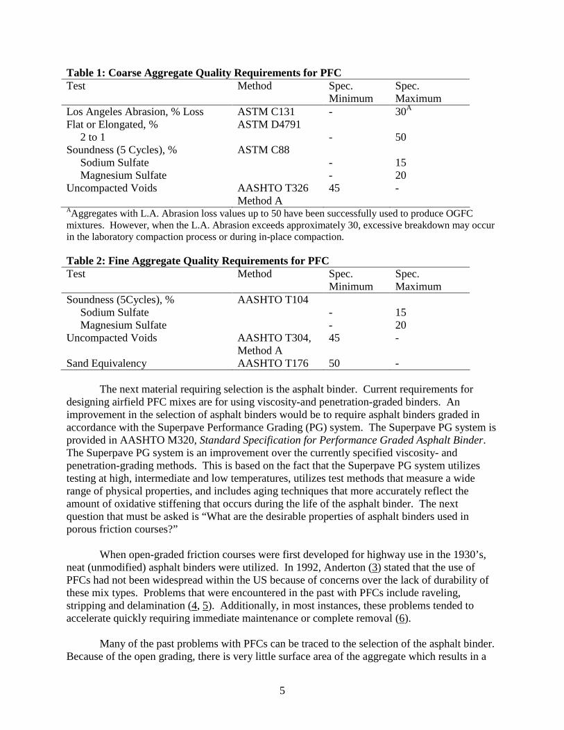
There are five primary aggregate characteristics that are important to the performance ofany HMA, including PFCs: angularity, shape, toughness, abrasion resistance, soundness andcleanliness. Tables 1 and 2 summarize the recommended aggregate characteristics for PFCsused on airfields.
5
Table 1: Coarse Aggregate Quality Requirements for PFCTest Method Spec.
MinimumSpec.Maximum
Los Angeles Abrasion, % Loss ASTM C131 - 30A
Flat or Elongated, % ASTM D47912 to 1 - 50
Soundness (5 Cycles), % ASTM C88Sodium Sulfate - 15Magnesium Sulfate - 20
Uncompacted Voids AASHTO T326 45 -Method A
AAggregates with L.A. Abrasion loss values up to 50 have been successfully used to produce OGFCmixtures. However, when the L.A. Abrasion exceeds approximately 30, excessive breakdown may occurin the laboratory compaction process or during in-place compaction.
Table 2: Fine Aggregate Quality Requirements for PFCTest Method Spec.
MinimumSpec.Maximum
Soundness (5Cycles), % AASHTO T104Sodium Sulfate - 15Magnesium Sulfate - 20
Uncompacted Voids AASHTO T304,Method A
45 -
Sand Equivalency AASHTO T176 50 -
The next material requiring selection is the asphalt binder. Current requirements fordesigning airfield PFC mixes are for using viscosity-and penetration-graded binders. Animprovement in the selection of asphalt binders would be to require asphalt binders graded inaccordance with the Superpave Performance Grading (PG) system. The Superpave PG system isprovided in AASHTO M320, Standard Specification for Performance Graded Asphalt Binder.The Superpave PG system is an improvement over the currently specified viscosity- andpenetration-grading methods. This is based on the fact that the Superpave PG system utilizestesting at high, intermediate and low temperatures, utilizes test methods that measure a widerange of physical properties, and includes aging techniques that more accurately reflect theamount of oxidative stiffening that occurs during the life of the asphalt binder. The nextquestion that must be asked is “What are the desirable properties of asphalt binders used inporous friction courses?”
When open-graded friction courses were first developed for highway use in the 1930’s,neat (unmodified) asphalt binders were utilized. In 1992, Anderton (3) stated that the use ofPFCs had not been widespread within the US because of concerns over the lack of durability ofthese mix types. Problems that were encountered in the past with PFCs include raveling,stripping and delamination (4, 5). Additionally, in most instances, these problems tended toaccelerate quickly requiring immediate maintenance or complete removal (6).
Many of the past problems with PFCs can be traced to the selection of the asphalt binder.Because of the open grading, there is very little surface area of the aggregate which results in a
6
relatively thick asphalt binder film coating the aggregates. At typical production/constructiontemperatures, the heavy film of asphalt binder had a propensity to drain from the aggregateskeleton, generally termed as draindown (6). Because of the draindown issues, a typical remedywas to reduce mixing and compaction temperatures (4). This reduction in temperature increasedthe viscosity of the asphalt binder which assisted in preventing the binder from draining from theaggregates. However, the reduction in temperature also led to the durability problems listedabove. First, because the production temperature of the PFC was reduced, all of the internalmoisture within the aggregates was not removed during production. Moisture remaining withinthe aggregates after production led to stripping of the asphalt binder film from the aggregateswhich resulted in the increased occurrence of raveling (7). Additionally, the reducedtemperatures prevented the new PFC from properly bonding with the tack coat placed on theunderlying layer. This lack of an adequate bond led to delamination problems (4).
Though the problems described above are not directly related to the fundamentalproperties of the asphalt binder, they were related to the viscous component of the asphalt binder.In a 1998 survey of state highway agencies, Kandhal and Mallick (5) stated that many of thehighway agencies which had experienced good performance with PFCs were utilizing modifiedasphalt binders and relatively high asphalt binder contents (by using fibers and/or relatively opengradations). Based upon the discussions provided on the past problems with PFCs, the use ofmodified asphalt binders makes sense. First, the increased viscosity of the asphalt binder helpsto hold the asphalt binder on the coarse aggregate structure reducing the potential for draindown.When combined with the proper use of fibers, modified asphalt binders have basically eliminateddraindown potential. Without the potential for draindown, production temperatures do not haveto be lowered.
The benefits of modified asphalt binders are not limited to helping prevent draindown. Aseries of reports and papers from the National Center for Asphalt Technology (NCAT) (8,9,10)have shown that the use of modified asphalt binders that provide high stiffness at typical in-service pavement temperature helps provide increased durability. Anderton (3) has also showedthat the addition of reclaimed rubber particles to the asphalt binder (i.e., increased viscosity)improved the performance of PFCs.
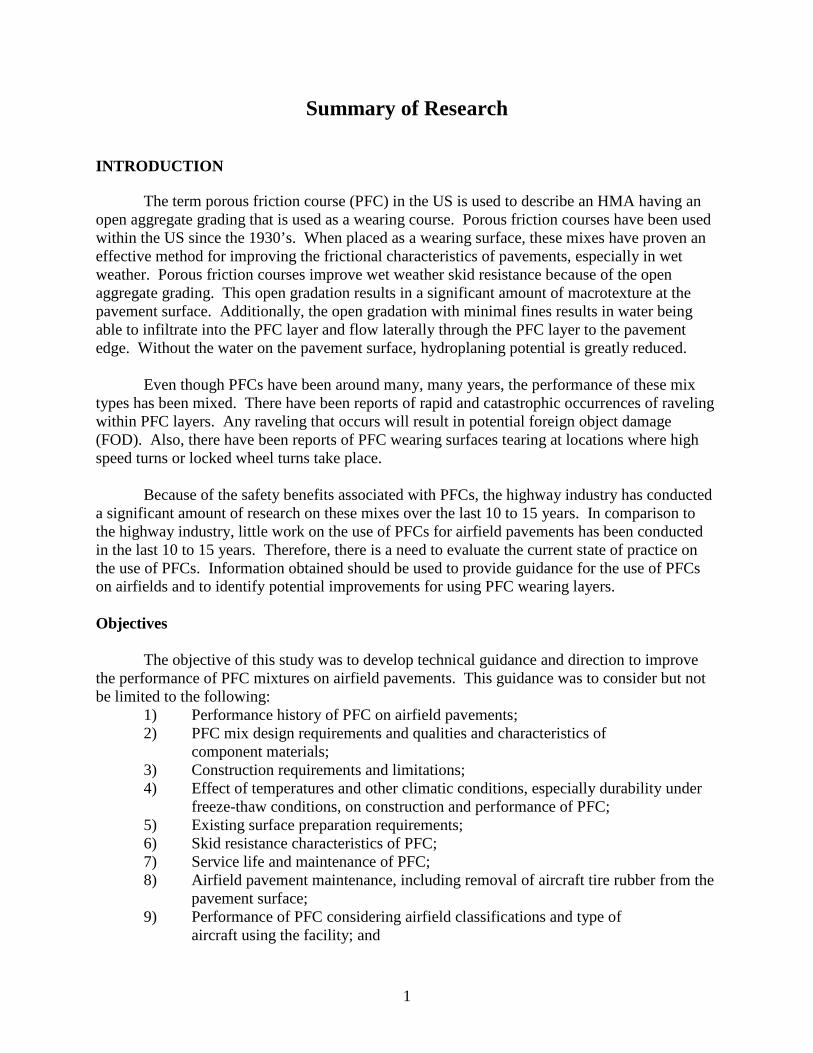
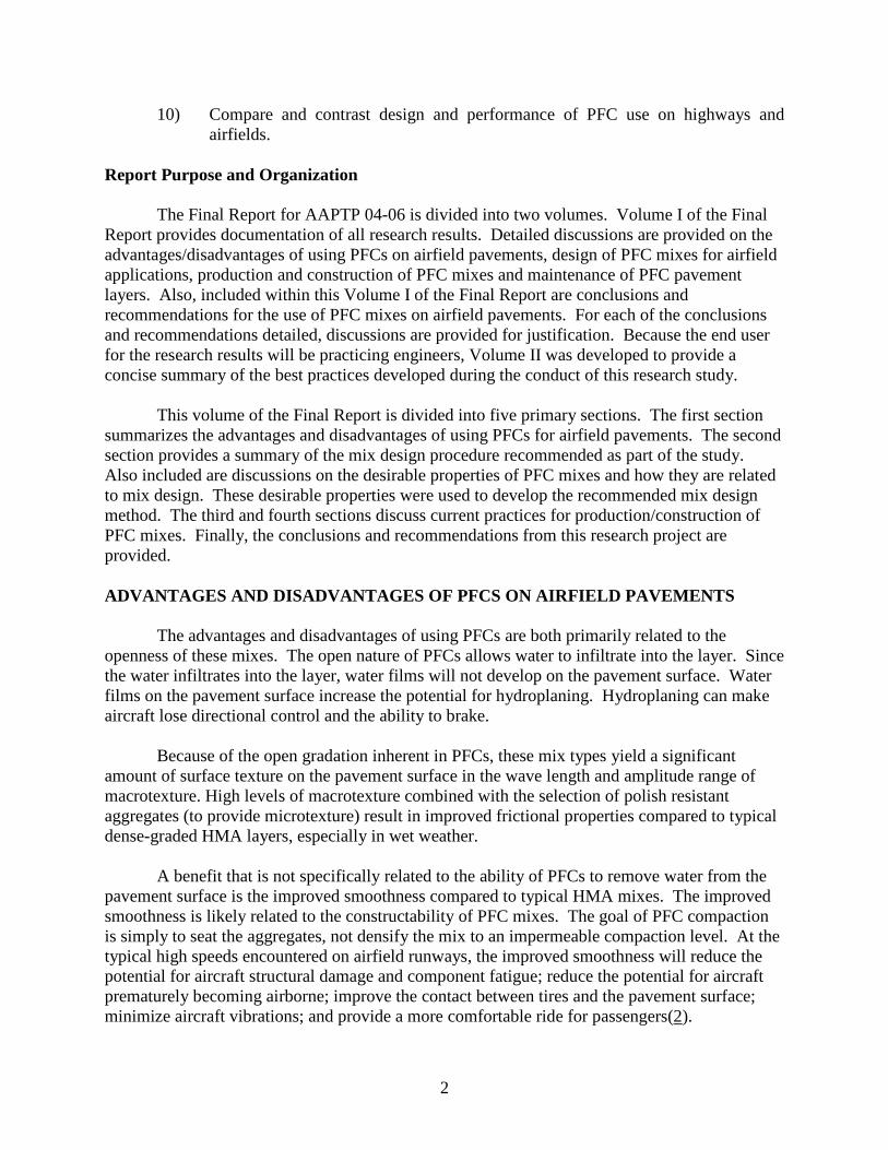
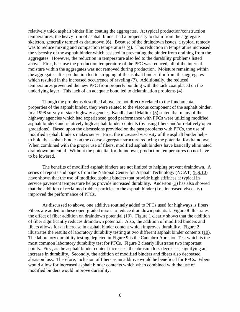
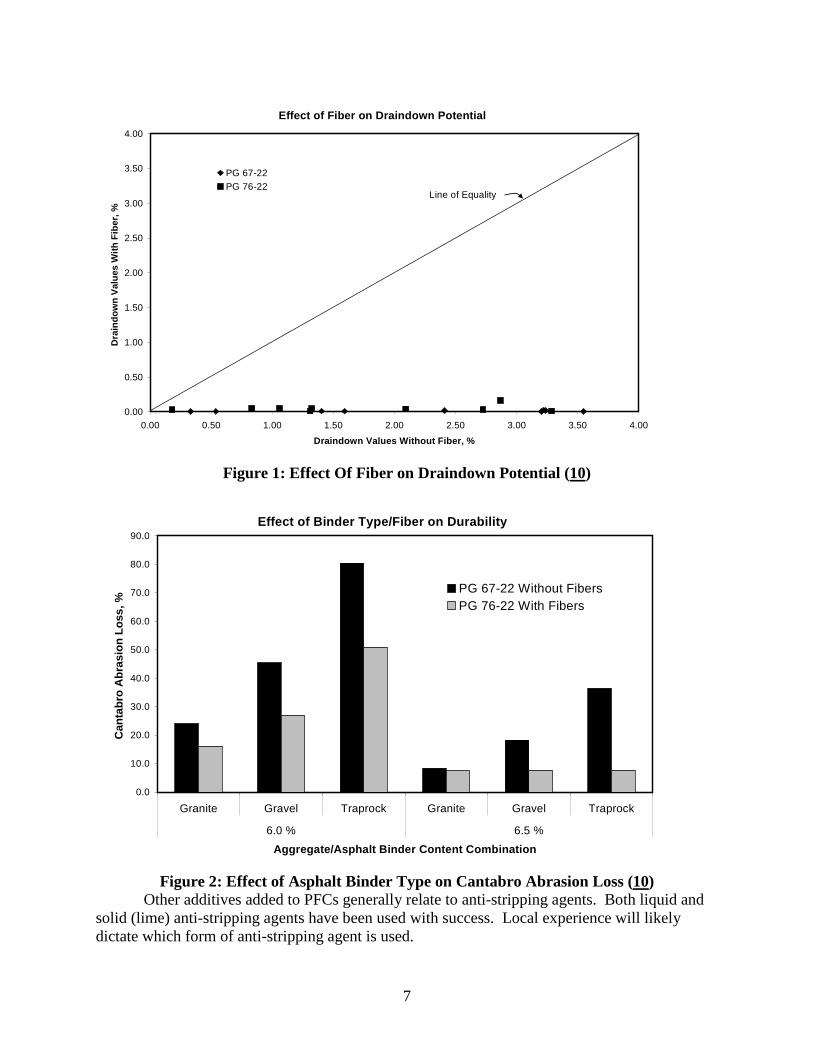
As discussed to above, one additive routinely added to PFCs used for highways is fibers.Fibers are added to these open-graded mixes to reduce draindown potential. Figure 8 illustratesthe effect of fiber addition on draindown potential (10). Figure 1 clearly shows that the additionof fiber significantly reduces draindown potential. Also, the addition of modified binders andfibers allows for an increase in asphalt binder content which improves durability. Figure 2illustrates the results of laboratory durability testing at two different asphalt binder contents (10).The laboratory durability testing depicted in Figure 9 is the Cantabro Abrasion Test which is themost common laboratory durability test for PFCs. Figure 2 clearly illustrates two importantpoints. First, as the asphalt binder content increases, the abrasion loss decreases, signifying anincrease in durability. Secondly, the addition of modified binders and fibers also decreasedabrasion loss. Therefore, inclusion of fibers as an additive would be beneficial for PFCs. Fiberswould allow for increased asphalt binder contents which when combined with the use ofmodified binders would improve durability.
7
Effect of Fiber on Draindown Potential
0.00
0.50
1.00
1.50
2.00
2.50
3.00
3.50
4.00
0.00 0.50 1.00 1.50 2.00 2.50 3.00 3.50 4.00
Draindown Values Without Fiber, %
Dra
ind
ow
nV
alu
es
Wit
hF
iber,
%
PG 67-22
PG 76-22Line of Equality
Figure 1: Effect Of Fiber on Draindown Potential (10)
Effect of Binder Type/Fiber on Durability
0.0
10.0
20.0
30.0
40.0
50.0
60.0
70.0
80.0
90.0
Granite Gravel Traprock Granite Gravel Traprock
6.0 % 6.5 %
Aggregate/Asphalt Binder Content Combination
Can
tab
roA
bra
sio
nL
oss
,%
PG 67-22 Without Fibers
PG 76-22 With Fibers
Figure 2: Effect of Asphalt Binder Type on Cantabro Abrasion Loss (10)Other additives added to PFCs generally relate to anti-stripping agents. Both liquid and
solid (lime) anti-stripping agents have been used with success. Local experience will likelydictate which form of anti-stripping agent is used.
8
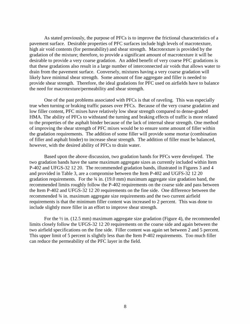
As stated previously, the purpose of PFCs is to improve the frictional characteristics of apavement surface. Desirable properties of PFC surfaces include high levels of macrotexture,high air void contents (for permeability) and shear strength. Macrotexture is provided by thegradation of the mixture; therefore, to provide a significant amount of macrotexture it will bedesirable to provide a very coarse gradation. An added benefit of very coarse PFC gradations isthat these gradations also result in a large number of interconnected air voids that allows water todrain from the pavement surface. Conversely, mixtures having a very coarse gradation willlikely have minimal shear strength. Some amount of fine aggregate and filler is needed toprovide shear strength. Therefore, the ideal gradations for PFC used on airfields have to balancethe need for macrotexture/permeability and shear strength.
One of the past problems associated with PFCs is that of raveling. This was especiallytrue when turning or braking traffic passes over PFCs. Because of the very coarse gradation andlow filler content, PFC mixes have relatively low shear strength compared to dense-gradedHMA. The ability of PFCs to withstand the turning and braking effects of traffic is more relatedto the properties of the asphalt binder because of the lack of internal shear strength. One methodof improving the shear strength of PFC mixes would be to ensure some amount of filler withinthe gradation requirements. The addition of some filler will provide some mortar (combinationof filler and asphalt binder) to increase shear strength. The addition of filler must be balanced,however, with the desired ability of PFCs to drain water.
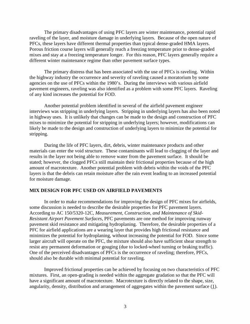
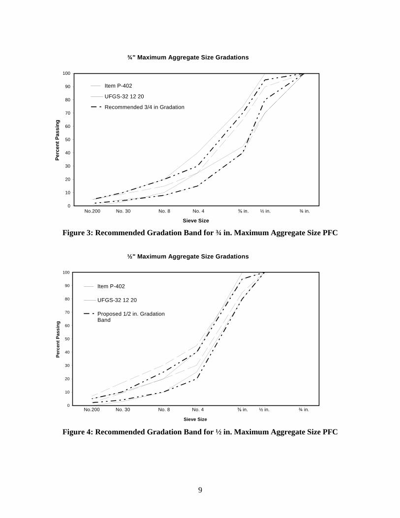
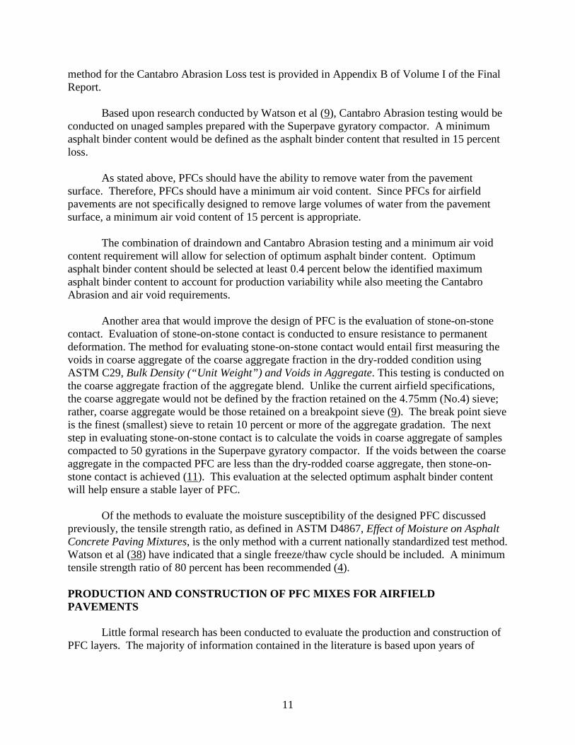
Based upon the above discussion, two gradation bands for PFCs were developed. Thetwo gradation bands have the same maximum aggregate sizes as currently included within ItemP-402 and UFGS-32 12 20. The recommended gradation bands, illustrated in Figures 3 and 4and provided in Table 3, are a compromise between the Item P-402 and UGFS-32 12 20gradation requirements. For the ¾ in. (19.0 mm) maximum aggregate size gradation band, therecommended limits roughly follow the P-402 requirements on the coarse side and pass betweenthe Item P-402 and UFGS-32 12 20 requirements on the fine side. One difference between therecommended ¾ in. maximum aggregate size requirements and the two current airfieldrequirements is that the minimum filler content was increased to 2 percent. This was done toinclude slightly more filler in an effort to improve shear strength.
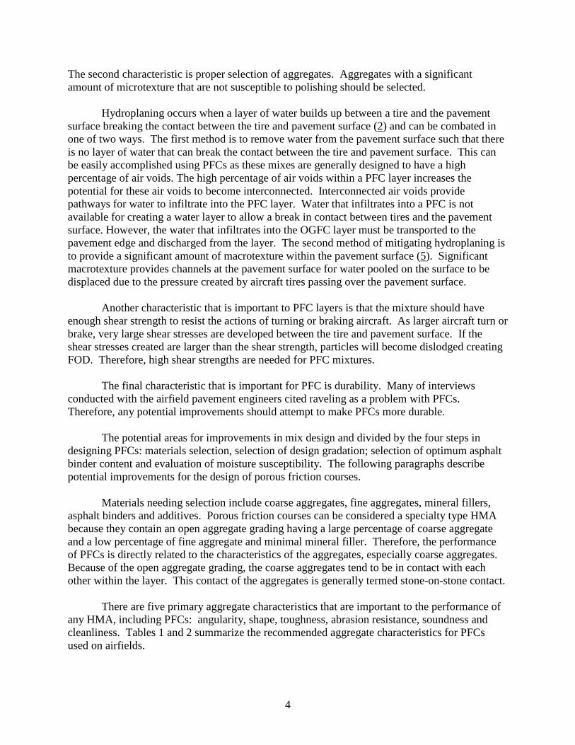
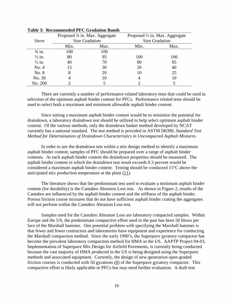
For the ½ in. (12.5 mm) maximum aggregate size gradation (Figure 4), the recommendedlimits closely follow the UFGS-32 12 20 requirements on the coarse side and again between thetwo airfield specifications on the fine side. Filler content was again set between 2 and 5 percent.This upper limit of 5 percent is slightly less than the Item P-402 requirements. Too much fillercan reduce the permeability of the PFC layer in the field.
9
¾" Maximum Aggregate Size Gradations
0
10
20
30
40
50
60
70
80
90
100
Sieve Size
Pe
rcen
tP
ass
ing
Item P-402
UFGS-32 12 20
Recommended 3/4 in GradationBand
¾ in.½ in.⅜ in.No. 4No. 8No. 30No.200
Figure 3: Recommended Gradation Band for ¾ in. Maximum Aggregate Size PFC
½" Maximum Aggregate Size Gradations
0
10
20
30
40
50
60
70
80
90
100
Sieve Size
Perc
en
tP
ass
ing
Item P-402
UFGS-32 12 20
Proposed 1/2 in. GradationBand
¾ in.½ in.⅜ in.No. 4No. 8No. 30No.200
Figure 4: Recommended Gradation Band for ½ in. Maximum Aggregate Size PFC
10
Table 3: Recommended PFC Gradation Bands
SieveProposed ¾ in. Max. Aggregate
Size GradationProposed ½ in. Max. Aggregate
Size GradationMin. Max. Min. Max.
¾ in. 100 100½ in. 80 95 100 100⅜ in. 40 70 80 95No. 4 15 30 20 40No. 8 8 20 10 25No. 30 4 10 4 10No. 200 2 5 2 5
There are currently a number of performance related laboratory tests that could be used inselection of the optimum asphalt binder content for PFCs. Performance related tests should beused to select both a maximum and minimum allowable asphalt binder content.
Since setting a maximum asphalt binder content would be to minimize the potential fordraindown, a laboratory draindown test should be utilized to help select optimum asphalt bindercontent. Of the various methods, only the draindown basket method developed by NCATcurrently has a national standard. The test method is provided in ASTM D6390, Standard TestMethod for Determination of Draindown Characteristics in Uncompacted Asphalt Mixtures.
In order to use the draindown test within a mix design method to identify a maximumasphalt binder content, samples of PFC should be prepared over a range of asphalt bindercontents. At each asphalt binder content the draindown properties should be measured. Theasphalt binder content in which the draindown test result exceeds 0.3 percent would beconsidered a maximum asphalt binder content. Testing should be conducted 15°C above theanticipated mix production temperature at the plant (11).
The literature shows that the predominant test used to evaluate a minimum asphalt bindercontent (for durability) is the Cantabro Abrasion Loss test. As shown in Figure 2, results of theCantabro are influenced by the asphalt binder content and the stiffness of the asphalt binder.Porous friction course mixtures that do not have sufficient asphalt binder coating the aggregateswill not perform within the Cantabro Abrasion Loss test.
Samples used for the Cantabro Abrasion Loss are laboratory compacted samples. WithinEurope and the US, the predominant compactive effort used in the past has been 50 blows perface of the Marshall hammer. One potential problem with specifying the Marshall hammer isthat fewer and fewer contractors and laboratories have equipment and experience for conductingthe Marshall compaction method. Since the early 1990’s, the Superpave gyratory compactor hasbecome the prevalent laboratory compaction method for HMA in the US. AAPTP Project 04-03,Implementation of Superpave Mix Design for Airfield Pavements, is currently being conductedbecause the vast majority of HMA produced in the US is being designed using the Superpavemethods and associated equipment. Currently, the design of new-generation open-gradedfriction courses is conducted with 50 gyrations (8) of the Superpave gyratory compactor. Thiscompactive effort is likely applicable to PFCs but may need further evaluation. A draft test
11
method for the Cantabro Abrasion Loss test is provided in Appendix B of Volume I of the FinalReport.
Based upon research conducted by Watson et al (9), Cantabro Abrasion testing would beconducted on unaged samples prepared with the Superpave gyratory compactor. A minimumasphalt binder content would be defined as the asphalt binder content that resulted in 15 percentloss.
As stated above, PFCs should have the ability to remove water from the pavementsurface. Therefore, PFCs should have a minimum air void content. Since PFCs for airfieldpavements are not specifically designed to remove large volumes of water from the pavementsurface, a minimum air void content of 15 percent is appropriate.
The combination of draindown and Cantabro Abrasion testing and a minimum air voidcontent requirement will allow for selection of optimum asphalt binder content. Optimumasphalt binder content should be selected at least 0.4 percent below the identified maximumasphalt binder content to account for production variability while also meeting the CantabroAbrasion and air void requirements.
Another area that would improve the design of PFC is the evaluation of stone-on-stonecontact. Evaluation of stone-on-stone contact is conducted to ensure resistance to permanentdeformation. The method for evaluating stone-on-stone contact would entail first measuring thevoids in coarse aggregate of the coarse aggregate fraction in the dry-rodded condition usingASTM C29, Bulk Density (“Unit Weight”) and Voids in Aggregate. This testing is conducted onthe coarse aggregate fraction of the aggregate blend. Unlike the current airfield specifications,the coarse aggregate would not be defined by the fraction retained on the 4.75mm (No.4) sieve;rather, coarse aggregate would be those retained on a breakpoint sieve (9). The break point sieveis the finest (smallest) sieve to retain 10 percent or more of the aggregate gradation. The nextstep in evaluating stone-on-stone contact is to calculate the voids in coarse aggregate of samplescompacted to 50 gyrations in the Superpave gyratory compactor. If the voids between the coarseaggregate in the compacted PFC are less than the dry-rodded coarse aggregate, then stone-on-stone contact is achieved (11). This evaluation at the selected optimum asphalt binder contentwill help ensure a stable layer of PFC.
Of the methods to evaluate the moisture susceptibility of the designed PFC discussedpreviously, the tensile strength ratio, as defined in ASTM D4867, Effect of Moisture on AsphaltConcrete Paving Mixtures, is the only method with a current nationally standardized test method.Watson et al (38) have indicated that a single freeze/thaw cycle should be included. A minimumtensile strength ratio of 80 percent has been recommended (4).
PRODUCTION AND CONSTRUCTION OF PFC MIXES FOR AIRFIELDPAVEMENTS
Little formal research has been conducted to evaluate the production and construction ofPFC layers. The majority of information contained in the literature is based upon years of
12
experience. Therefore, this chapter contains guidance for producing and constructing PFC layersin the form of a best practices document.
Similar to any HMA mixture, construction of PFC pavement layers includes four primaryphases: production, transportation, placement and compaction. Another very important aspect ofconstruction is quality control/quality assurance (QC/QA). Many of the best practices forconstructing PFC pavement layers can be taken from the construction of SMA (4). Both mixtypes utilize a large fraction of coarse aggregates and generally require the use of stabilizingadditives. Therefore, in addition to the literature, reports and interviews dealing with PFCs,guidelines developed for constructing SMA (11) were also consulted to develop guidelines onthe construction of PFCs. Another valuable reference utilized during the development ofguidelines was the “Hot-Mix Asphalt Paving Handbook (2000)” (1).
As with the construction of any HMA pavement layer, quality begins with properaggregate stockpile management. Stockpiles should be built on sloped, clean, stable surfaceswith the different stockpiles kept separated (12). Low moisture contents and low moisturecontent variability will allow for easier control of mixing temperature (7).
A PFC mixture must contain a high percentage of coarse aggregate in order to providethe desired high air void contents and, thus, benefits related to permeability. Since the coarseaggregate gradation can have a tremendous effect on the quality of the PFC mixture produced,consideration should be given to feeding the coarse aggregate stockpile through more than onecold feed bin to provide better control over the production process. Using more than one coldfeed bin for the coarse aggregate will minimize variability in the coarse aggregate gradation (12).
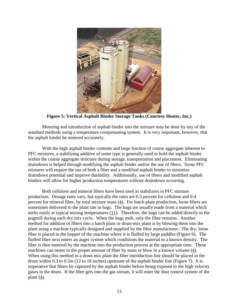
Porous friction course mixtures may require that some type of modifier be used in orderto enhance binder properties. These products may require special blending through a shear millor extra agitation and time for dispersion. The blending needed is usually done at an asphaltrefinery or terminal. Since the modifier particles may have a different specific gravity than thebinder they are used in, there is some concern that the modifier particles may separate out over aperiod of time. This concern has led some agencies to require additional tests, such as aseparation test. Contractors are also required to provide asphalt storage containers that willprovide continuous agitation of the binder in order to avoid any separation of binder andmodifier. Vertical storage tanks (Figure 12) are often used in place of conventional horizontaltanks because the efficiency of agitation and product circulation may be improved.
13
Figure 5: Vertical Asphalt Binder Storage Tanks (Courtesy Heatec, Inc.)
Metering and introduction of asphalt binder into the mixture may be done by any of thestandard methods using a temperature compensating system. It is very important, however, thatthe asphalt binder be metered accurately.
With the high asphalt binder contents and large fraction of coarse aggregate inherent toPFC mixtures, a stabilizing additive of some type is generally used to hold the asphalt binderwithin the coarse aggregate structure during storage, transportation and placement. Eliminatingdraindown is helped through modifying the asphalt binder and/or the use of fibers. Some PFCmixtures will require the use of both a fiber and a modified asphalt binder to minimizedraindown potential and improve durability. Additionally, use of fibers and modified asphaltbinders will allow for higher production temperatures without draindown occurring.
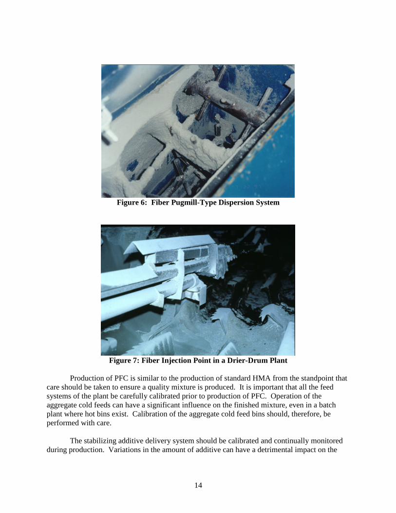
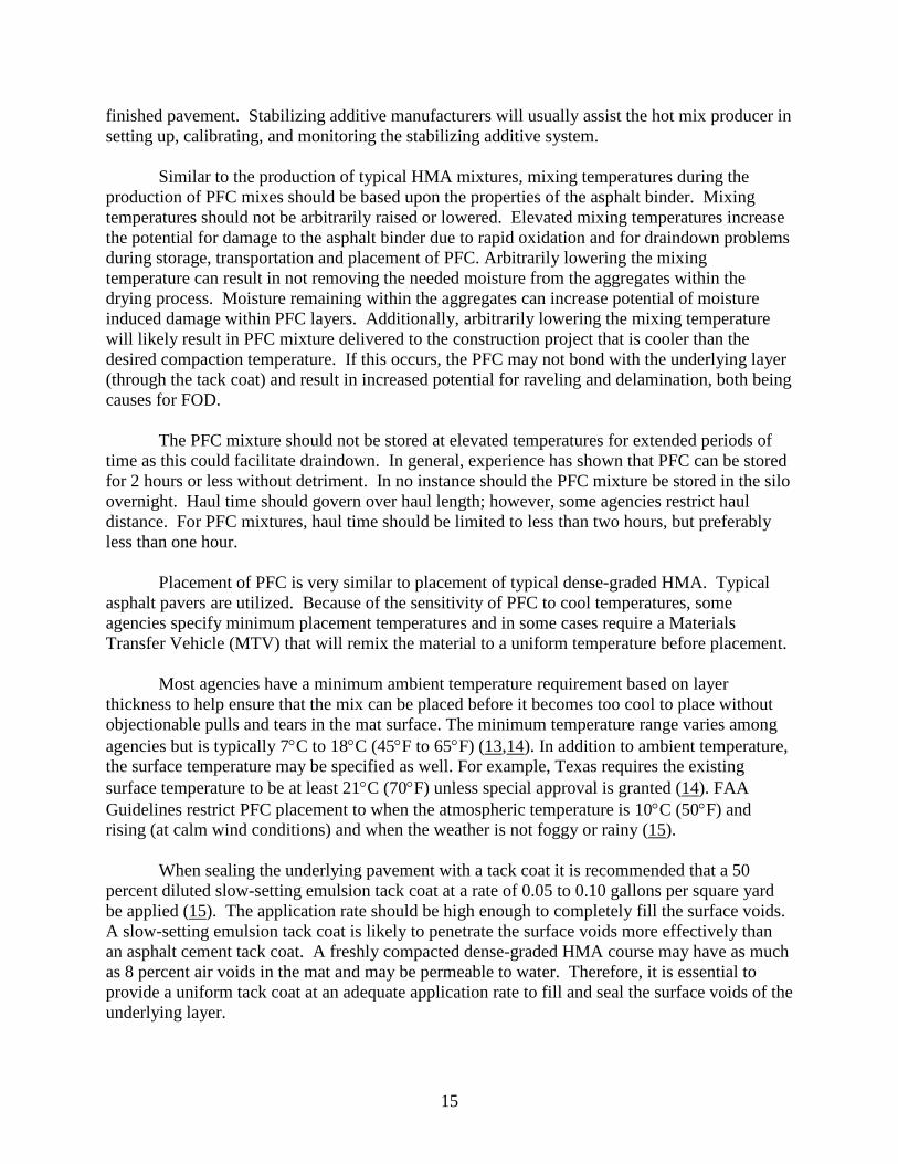
Both cellulose and mineral fibers have been used as stabilizers in PFC mixtureproduction. Dosage rates vary, but typically the rates are 0.3 percent for cellulose and 0.4percent for mineral fiber, by total mixture mass (4). For batch plant production, loose fibers aresometimes delivered to the plant site in bags. The bags are usually made from a material whichmelts easily at typical mixing temperatures (11). Therefore, the bags can be added directly to thepugmill during each dry mix cycle. When the bags melt, only the fiber remains. Anothermethod for addition of fibers into a batch plant or drum-mix plant is by blowing them into theplant using a machine typically designed and supplied by the fiber manufacturer. The dry, loosefiber is placed in the hopper of the machine where it is fluffed by large paddles (Figure 6). Thefluffed fiber next enters an auger system which conditions the material to a known density. Thefiber is then metered by the machine into the production process at the appropriate time. Thesemachines can meter in the proper amount of fiber by mass or blow in a known volume (4).When using this method in a drum mix plant the fiber introduction line should be placed in thedrum within 0.3 to 0.5m (12 to 18 inches) upstream of the asphalt binder line (Figure 7). It isimperative that fibers be captured by the asphalt binder before being exposed to the high velocitygases in the drum. If the fiber gets into the gas stream, it will enter the dust control system of theplant (4).
14
Figure 6: Fiber Pugmill-Type Dispersion System
Figure 7: Fiber Injection Point in a Drier-Drum Plant
Production of PFC is similar to the production of standard HMA from the standpoint thatcare should be taken to ensure a quality mixture is produced. It is important that all the feedsystems of the plant be carefully calibrated prior to production of PFC. Operation of theaggregate cold feeds can have a significant influence on the finished mixture, even in a batchplant where hot bins exist. Calibration of the aggregate cold feed bins should, therefore, beperformed with care.
The stabilizing additive delivery system should be calibrated and continually monitoredduring production. Variations in the amount of additive can have a detrimental impact on the
15
finished pavement. Stabilizing additive manufacturers will usually assist the hot mix producer insetting up, calibrating, and monitoring the stabilizing additive system.
Similar to the production of typical HMA mixtures, mixing temperatures during theproduction of PFC mixes should be based upon the properties of the asphalt binder. Mixingtemperatures should not be arbitrarily raised or lowered. Elevated mixing temperatures increasethe potential for damage to the asphalt binder due to rapid oxidation and for draindown problemsduring storage, transportation and placement of PFC. Arbitrarily lowering the mixingtemperature can result in not removing the needed moisture from the aggregates within thedrying process. Moisture remaining within the aggregates can increase potential of moistureinduced damage within PFC layers. Additionally, arbitrarily lowering the mixing temperaturewill likely result in PFC mixture delivered to the construction project that is cooler than thedesired compaction temperature. If this occurs, the PFC may not bond with the underlying layer(through the tack coat) and result in increased potential for raveling and delamination, both beingcauses for FOD.
The PFC mixture should not be stored at elevated temperatures for extended periods oftime as this could facilitate draindown. In general, experience has shown that PFC can be storedfor 2 hours or less without detriment. In no instance should the PFC mixture be stored in the siloovernight. Haul time should govern over haul length; however, some agencies restrict hauldistance. For PFC mixtures, haul time should be limited to less than two hours, but preferablyless than one hour.
Placement of PFC is very similar to placement of typical dense-graded HMA. Typicalasphalt pavers are utilized. Because of the sensitivity of PFC to cool temperatures, someagencies specify minimum placement temperatures and in some cases require a MaterialsTransfer Vehicle (MTV) that will remix the material to a uniform temperature before placement.
Most agencies have a minimum ambient temperature requirement based on layerthickness to help ensure that the mix can be placed before it becomes too cool to place withoutobjectionable pulls and tears in the mat surface. The minimum temperature range varies amongagencies but is typically 7C to 18C (45F to 65F) (13,14). In addition to ambient temperature,the surface temperature may be specified as well. For example, Texas requires the existingsurface temperature to be at least 21C (70F) unless special approval is granted (14). FAAGuidelines restrict PFC placement to when the atmospheric temperature is 10C (50F) andrising (at calm wind conditions) and when the weather is not foggy or rainy (15).
When sealing the underlying pavement with a tack coat it is recommended that a 50percent diluted slow-setting emulsion tack coat at a rate of 0.05 to 0.10 gallons per square yardbe applied (15). The application rate should be high enough to completely fill the surface voids.A slow-setting emulsion tack coat is likely to penetrate the surface voids more effectively thanan asphalt cement tack coat. A freshly compacted dense-graded HMA course may have as muchas 8 percent air voids in the mat and may be permeable to water. Therefore, it is essential toprovide a uniform tack coat at an adequate application rate to fill and seal the surface voids of theunderlying layer.
16
PFC mixtures are placed using conventional asphalt pavers. However, a hot screed isvery important to prevent pulling of the mat. A propane torch or some other means to heat thepaver screed before each startup is important.
Transverse joints at the beginning and end of a project may need a transition area for thelayer to taper from minimum thickness to the specified plan thickness. To avoid a rough bump atthese transverse joints, it may be necessary to mill a short taper that will provide the proper depthfor which to begin the layer. When constructing the transverse joint, spacers are to be addedunder the screed to provide for the necessary uncompacted depth.
Longitudinal joints should be constructed by overlapping the previous lane placed byabout 12.5 mm (1/2 inch). This small amount of overlap will eliminate the need for raking thejoint but will provide enough mixture to minimize raveling or joint separation as one mightencounter with dense-graded mixtures. Care should be taken to see that the vertical face of thelongitudinal joint is not tacked because that would result in impeded flow of water across thepavement from adjoining sections or lanes.
Conventional steel wheel rollers are used to compact the PFC. No pneumatic tire rollingis required. It is critical to keep the roller within 15 m (50 ft) of the paver to compact while it isstill hot and workable. The breakdown roller usually completes one to two complete coverage ofthe mat in static mode to compact a thin lift (20 mm or ¾ in) PFC.
No minimum density is recommended for PFC. Two or three rollers are typically used inconventional HMA construction. This number normally serves well for PFC also. Steel wheeledrollers weighing 9 Mg (10 tons) should be used when compacting the PFC mixture (16). Rollerspeed should not exceed 5 km/hr (3 miles/hr) and the drive roll should be kept nearest the paver.Two to four passes of the breakdown rollers should be sufficient. If it becomes necessary for therollers to sit idle they should be taken off the mat if possible. Idle rollers sitting on the mat cancause unnecessary roughness in the finished surface. Vibratory rollers should not be used onPFC mainlines. The breakdown roller may have to be operated in a vibratory mode at transversejoints and occasionally longitudinal joints to help knock down a high joint. Generally, use ofvibratory compaction should be discouraged. The vibration of the roller may break aggregateand/or force the mortar to the surface of the mat. Pneumatic-tired rollers are not recommendedfor use on PFC. The rubber tires tend to pick up the mortar causing surface deficiencies.
Porous friction course mixture furnished by the contractor should conform to the job-mixformula requirements, within allowable deviations from the targets. Testing included within aquality control/quality assurance program should include gradations, asphalt binder content anddraindown. Gradations and asphalt binder content testing is conducted to provide an indicationthat the mixture is produced according to the job mix formula, while draindown testing isconducted to ensure that the stabilizing additives are being properly added.
After completion of construction, smoothness testing should be conducted. Smoothnesstesting should be conducted to ensure that construction practices occurred that would notadversely affect operational control of aircraft.
17
MAINTENANCE OF PFC AIRFIELD PAVEMENTS
The FAA has AC 150/5380-6A dated July 14, 2003, Guidelines and Procedures forMaintenance of Airport Pavements, which recommends actions to undertake during preventiveand remedial maintenance of rigid and flexible airfield pavements. However, the open nature ofPFC compared to conventional dense-graded asphalt pavements, requires specific general andwinter maintenance.
A substantial amount of research (4, 17) has been conducted and published in the US andEurope concerning general and winter maintenance of PFC highway pavement layers. Thisresearch is applicable to PFC airfield pavements as well. However, airfield pavements havespecial requirements because of wider runway pavements which must be effective in removingwater over longer distances; keeping the pavement surface completely free from FOD; rubberbuildup which will also diminish the ability of the PFC in removing water from the surface; andthe need for prompt and effective control of snow and ice in view of airfield safety. Therefore,general and winter maintenance of PFC pavements specific to airfield pavements is discussedhere.
General maintenance consists of cleaning clogged PFC; removal of rubber buildup;preventive surface maintenance; corrective surface maintenance; and rehabilitation. Porousfriction course may gradually be choked and partially lose its permeability (4). Therefore,frequent cleaning may be necessary. A high pressure cleaner, has been found to be most effectivebased on permeability tests after cleaning in Switzerland (18). A piece of equipment wasrecently reported on at the meeting of the International Conference on Asphalt Pavements held inCopenhagen, Denmark (19). A high-pressure water blast (860 kPa or 125 psi) followed by avacuum to remove the solids and water is used in Denmark. Experienced contractors withspecialized equipment do such work.
Rubber buildup is a problem on all types of airfield pavements including PFC. Whenaircrafts land considerable heat is generated due to friction between tires and pavement, whichcauses deposition of tire rubber in a thin layer on the airfield pavement. With repeated landingsof aircrafts more and more rubber fills the macrotexture of the pavement surface and thepavement continues to lose its wet weather skid resistance. As tire rubber builds up it can alsoaffect the ability of PFC to drain water. If sufficient rubber exists on a PFC surface, water maypool on the rubber leading to an increased potential of hydroplaning. The use of continuousfriction measuring equipment (CFME) should assist in deciding when maintenance related torubber buildup is required.
Unified Facilities Guide Specifications UFGS S-32 01 11.52 dated April 2006 pertains torunway rubber removal requirements. These specifications list the rubber removal equipments asfollows:
A. Mechanical Rubber Removal EquipmentMechanical rubber removal equipment includes water blasting, shot blasting, sandblasting,
and other non-chemical systems. The specifications state that the equipment to be used onasphalt concrete should be controlled to remove rubber accumulations and minimize disturbance
18
to asphalt mixtures. The specifications also state, “Extremely good control shall be exercised forporous friction courses.” Water blasting uses water only, shot blasting involves propellingabrasive particles at high velocities on the rubber. Sandblasting produces a pressurized stream ofsand and air to remove rubber from the pavement surface without filling voids with debris inasphalt pavements. However, intuitively it may be difficult to shot blast or sandblast PFCmixtures without filling some voids with sand. It is also quite possible that shot blasting andsandblasting may be too harsh for PFC, but this needs to be investigated in controlled field trials.
B. Chemical Rubber Removal EquipmentChemicals that are environmentally safe and effective in cleaning rubber deposits have been
developed. The chemicals are sprayed on the surface, scrubbed, brushed, and worked into rubberfor about four hours or more. The chemicals break down the rubber into a soft, jelly-likematerial, which is then flushed off by water blasting. It is not known whether chemical methodhas been tried in the case of rubber buildup on PFC. It is unclear whether the chemicals willharm the asphalt-rubber binder contained within some PFCs.
It is expected that the asphalt binder in the PFC pavement will get oxidized and becomebrittle after many years’ service. This may precipitate surface raveling, which is a potentialsource for FOD. Many highway agencies have used fog seals to perform preventive maintenanceof PFC pavements. Fog seals provide a thin film of neat asphalt binder at the surface and,therefore, are believed to extend the life of PFC pavements (20).
Occasionally, the PFC airfield pavement will require repair of delaminated areas and/orpotholes. Milling and inlay using PFC mix has been recommended by the Oregon Department ofTransportation to repair PFC when the quantities of material are enough to justify this activity. Ifonly a small quantity is needed, a dense-graded conventional asphalt mix is suggested for suchpatch repairs (20). When the patched area is small and the flow of water around the patch can beensured, use of dense-graded asphalt mix can be considered. Rotation of the patch to 45 degreeto provide a diamond shape is recommended because it will facilitate the flow of water along thedense mix patch and will also diminish wheel impact on the patch joint (20). When patch repairsare made with PFC material, only a light tack coat (preferably emulsion) should be applied to thevertical faces of the existing pavement. Heavy tack coat will impede the flow of water throughthe patch.
The PFC airfield pavement can also develop transverse and longitudinal cracks while inservice. There is no problem in sealing the transverse cracks because the crack sealer will notimpede the flow of water within the PFC, which takes place in a transverse direction. Suchcracks can be sealed in accordance with procedures and crack sealing materials (such asrubberized asphalt binder) given in FAA AC 150/5380-6A. Sealing longitudinal cracks in PFC isproblematic because the crack sealer would impede the transverse flow of water within the PFC.One potential solution, although expensive, is to mill off the PFC in a narrow strip right over thelongitudinal crack and place an inlay with PFC material. If the longitudinal crack is also presentin the underlying course, it must be sealed properly. Again, only a light tack coat should beapplied to the vertical faces of the existing pavement.
19
If the PFC has lost its functionality in terms of permeability only and has not lost itsintegrity, it can be allowed to remain service because it will behave essentially like a dense-graded asphalt course with low permeability (6). However, if PFC must be rehabilitated becauseit has developed raveling, delamination, or potholes it is recommended to mill it off and replacewith new PFC. Direct placement of new dense-graded asphalt course over existing PFC is notrecommended because water/moisture accumulation in the existing PFC layer is likely to inducestripping in the overlying dense asphalt course (and possibly delamination) and thus shorten itslife.
Winter maintenance (snow and ice removal) has often been cited and assumed to be aserious problem with PFC. However, there has been little difficulty in this regard in Europe.Porous friction course has different thermal and icing properties than conventional dense-gradedasphalt pavement, and needs its own winter maintenance regimen. Porous friction course, being amix with high air voids, has a different thermal conductivity (40 to 70 percent less than denseasphalt pavement) and, therefore, acts like an insulating layer. Porous friction course may have atemperature of 2° C lower than dense asphalt pavement. Frost and ice will accumulate earlier,more quickly, and more frequently on PFC compared to other surfaces. These conditions mayalso persist for longer periods. Therefore, larger amounts and more frequent applications ofdeicer agents are required; which increase maintenance costs for PFC.
It is important to give special and repeated training to drivers of snowplows andspreaders. The FHWA recommends developing snow and ice control for PFC using chemicaldeicers and plowing and avoiding the use of abrasive materials such as sand to improve tractionbecause such materials are likely to choke the PFC (7). “Preventive salting” of the PFC at theright time is important as practiced in Britain (21). They also resort to prompt plowing of snowusing plows fitted with rubber edges on the blade to prevent surface damage to PFC. Salting isonly successful on a dry pavement when temperatures are lower than –10°C. A combination of70 percent dry salt and 30 percent salt-water solution (20 percent calcium chloride) applied at therate of 10-20 grams per sq. meter has been determined to be effective in Austria (22). It has beenfound in Holland that the use of brine is extremely effective and reduces the salt consumption toonly 15 percent of normal. Brine cannot be used effectively on dense surfaces because it wouldrun off quickly (22). According to experience in Netherlands (23) about 25 percent more salt isrequired for PFC. The timing of application is very important. Up to 50 percent increase in saltuse has been reported in Italy for PFC compared to dense asphalt pavements. An interestingobservation from Italy is that the amount of salt diminishes as the maximum aggregate size of thePFC decreases (24). By reducing the maximum aggregate size from 20 mm to 16 mm, roadconditions improve 15 percent during the winter months and the amount of salt is reducedsignificantly.
Black ice can also form on the PFC if water is allowed to accumulate. Pre-wetted saltsseem to work quite well on black ice according to experience in Denmark and the Netherlands(15). Calcium chloride and pre-wetted salt are used there to ensure even distribution of the saltand to prevent formation of black ice.
It is evident from the preceding discussion that a lot of experience has been gained in theUS and Europe in snow and ice control on PFC highway pavements, which can also be applied
20
to PFC airfield pavements. It is also evident that the experiences presented above do not allagree of Volume I of the Final Report.
CONCLUSIONS AND RECOMMENDATIONS
This section provides conclusions and recommendations derived from the workconducted during this project. Specific conclusions presented herein are based upon theinterviews of airfield pavement engineers, literature reviews and experiences of the researchteam. Recommendations are divided into two different categories: potential improvements andadditional research needed. Recommendations categorized as potential improvements are thosethat the research indicates would improve the current state of practice for airfield PFC. Some ofthe recommendations that are categorized as potential improvements to the current state ofpractice may require additional work in order to become implementable; therefore, somerecommendations are listed under the category of additional research needed.
Based upon the research conducted during this project, a draft Engineering Brief whichprovides a revised Item P-402 specification was developed. This draft Engineering Brief isprovided in Appendix C.
Conclusions
Porous friction courses are a specialty type hot mix asphalt that are designed to have anopen aggregate grading and used as a wearing surface on airfield runways. The followingconclusions are provided based upon the research conducted during this project.
Porous friction courses are an effective method for improving the frictional properties ofairfield pavements, especially during wet weather. The improved wet weather frictionalcharacteristics are derived from the open aggregate grading. The open aggregate gradingallows water to infiltrate into the PFC layer and also results in a significant amount ofmacrotexture.
Porous friction courses used as a wearing surface significantly reduce the potential forhydroplaning on airfield runways. This reduce in hydroplaning potential is also related tothe open aggregate grading.
Porous friction courses produce lower frictional speed gradients than dense-graded HMAwearing layers. Therefore, PFCs maintain their improved frictional properties at higherspeeds.
Porous friction courses provide higher values of macrotexture than typical dense-gradedHMA wearing layers.
Immediately after construction, the frictional properties of PFC wearing layers are lowerwhen braking with locked wheels. This is because of the relatively thick film of asphaltbinder that coats the aggregate with a PFC layer. When the wheel locks, the thin film ofasphalt binder will melt creating a slippery surface. This is only true when wheels lockduring breaking. Frictional properties will improve after the as asphalt is worn off byaircraft operations.
21
Porous friction courses result in smoother wearing surfaces compared to typical typeddense-graded HMA surfaces. Smooth wearing layers improve aircraft operationalcontrol.
Porous friction courses have different thermal properties than typical dense-graded HMA.The temperature of PFC wearing layers will drop below freezing sooner than dense-graded layers and stay below freezing for a longer time. Therefore, winter maintenancepractices will generally be different for PFC layers compared to dense-graded layers.
Snow plows can damage PFC wearing layers. Use of rubber tipped snow plow bladescan reduce the potential for damage to PFC layers.
Porous friction courses will generally not last as long as dense-graded HMA layers.Porous friction courses will generally last for 8 to12 years while dense-graded layers willlast for 10 to 15 years.
Rapid deterioration of PFC layers due to raveling have been reported. Also, there arereports of delamination problems with PFCs. Raveling and delamination increase FOD.
Research conducted on OGFCs for highways shows improved durability when modifiedasphalt binders are used in the mixture.
Proper addition of stabilizing additives in PFCs will significantly reduce the potential fordraindown. Stabilizing additives include asphalt binder modifiers and/or fibers.
Use of performance graded asphalt binders is an improvement over the viscosity orpenetration graded asphalt binders.
Use of modified asphalt binders and fibers improves the durability of PFC mixes asmeasured by the Cantabro Abrasion Loss test.
Use of stabilizing additives allows higher production temperatures. Both cellulose and mineral fibers have been successfully incorporated into PFC mixes. Vertical faces of longitudinal joints should not be tacked. Tacking of these vertical faces
will impede the flow of water through the PFC layer. Compaction of PFC layers should be accomplished using 9 Mg (10 ton) steel wheel
rollers. Compaction should be conducted to seat the aggregates and not to a specificdensity.
Pneumatic-tired rollers should not be used to compact PFC mixes. Porous friction courses can be clogged over time due to dust and debris infiltrating the
void structure or rubber build-up. The experiences of agencies for winter maintenance are mixed. Some agencies report an
increase in the usage of deicing salts while some agencies report less need for deicingsalts when combined with the use of brine.
Recommendations
As stated above, recommendations are divided into three categories: implementable,potential improvements, and additional research needed. Following are recommendations basedupon the research conducted in this report.
22
Potential Improvements
The design of PFC mixes used for airfield pavement should include four primary steps.First, suitable materials should be selected to comprise the PFC mix. Next, the selectedaggregates should be used to blend trial gradations. Included within this second step isalso evaluation of the trial gradations in order to select the design gradation. The thirdstep in the mix design procedure is to select the design optimum asphalt binder contentfor the selected gradation. The final step would be to evaluate the designed mixture.
The Los Angeles Abrasion and Impact test should be used to evaluate coarse aggregatetoughness. A maximum percent loss of 30 percent should be specified. However, ifexperience suggests that coarse aggregate yielding higher loss vales will performsatisfactorily they should be allowed. In no circumstance should aggregate having morethan 50 percent loss be allowed.
The flat or elongated test should be used to specify coarse aggregate particle shapeutilizing a critical ratio of 2:1. A maximum of 50 percent flat or elongated particlesshould be specified.
Both sodium and magnesium sulfate soundness should be allowed to evaluate thesoundness of aggregates. Maximum loss values should be 15 and 20 percent,respectively.
Coarse aggregate angularity should be specified using the uncompacted voids in coarseaggregate test. A minimum percent voids of 45 percent should be specified.
Fine aggregate angularity should be specified using the uncompacted voids in fineaggregate test. A minimum percent voids of 45 percent should be specified.
The cleanliness of fine aggregates should be specified using the sand equivalency test. Aminimum clay content of 50 percent should be specified.
Modified asphalt binders should be used within PFC mixtures to improve durability. Stone-on-stone contact should be specified when designing PFC mixes for airfield
pavement layers. Ensuring stone-on-stone contact will result in a stable layer of PFC. A minimum asphalt binder content should be specified to yield a durable PFC. The
minimum asphalt binder content should be based upon the combined bulk specific gravityof the aggregates.
Draindown testing should be utilized during mix design. The draindown basket methodshould be utilized for this testing. A maximum percent draindown of 0.3 percent, by totalmix mass, should be specified. Testing of the mixture should be conducted 15°C higherthan the anticipated production temperature.
Mixing and compacting temperature should be based upon the properties of the asphaltbinder.
The Cantabro Abrasion test should be utilized within the design of PFC mixes. TheCantabro Abrasion test is a performance related test used to evaluate the durability ofPFC mixes.
Silo storage time should be limited to two hours. Haul time should be limited to two hours.
23
Recommendations and Future Research
The proposed draft mix design for PFC mixes should be laboratory and field validated. Research should be conducted to evaluate methods of cleaning PFC layers. Clogged
from debris. Clogged PFC layers lose the ability to remove water from the pavementsurface.
Research should be conducted on the best method(s) for removing rubber buildup onairfield runways.
Research should be conducted to evaluate the effect of chemical rubber removal on PFCsthat utilize rubber modified asphalt binder.
Research should be conducted to evaluate winter maintenance activities for PFC layers. Research should be conducted to evaluate the best method(s) for rehabilitation of PFC
layers.
REFERENCES
1. Titus-Glover, L. and S.D. Tayabji. “Assessment of LTPP Friction Data.” ReportFHWA-RD-99-037. Federal Highway Administration, March 1999.
2. Johnson, E. A. and T. D. White. “Porous Friction Course Solves Airport HydroplaningProblem.” Civil Engineering. American Society of Civil Engineers. Volume 46, No. 4.pp 90-92. April 1976.
3. Anderton, G.L. “Evaluation of Asphalt Rubber Binders in Porous Friction Courses.”Technical Report CPAR-GL-92-1. US Army Corps of Engineer. Waterways ExperimentStation. May 1992.
4. Kandhal, P.S. “Design, Construction, and Maintenance of Open-Graded Asphalt FrictionCourses.” National Asphalt Pavement Association. Information Series 115. Lanham,Maryland. 2002.
5. Kandhal, P.S. and R. B. Mallick. “Open-Graded Friction Course: State of the Practice.”Transportation Research Circular E-C005. Transportation Research Board. NationalResearch Council. Washington, D.C. 1998.
6. Huber, G. NCHRP Synthesis 284. “Performance Survey on Open-Graded Friction CourseMixes.” Transportation Research Board. National Research Council. Washington, D.C.2000.
7. Technical Advisory T 5040.31, US Department of Transportation, Federal HighwayAdministration. Washington, D.C. December 26, 1990.
8. Mallick, R.B., P.S. Kandhal, L.A. Cooley, Jr., and D. E. Watson. “Design, Constructionand Performance of New-Generation Open-Graded Friction Course.” Journal of theAssociation of Asphalt Paving Technologists. Volume 69. pp 391-423. 2000.
9. Watson, D.E., K. A. Moore, K. Williams, and L. A. Cooley, Jr. “Refinement of NewGeneration Open-Graded Friction Course Mix Design.” Journal of the TransportationResearch Record. No. 1832. Transportation Research Board. National Research Council.pp 78-85. 2003.
24
10. Watson, D.E., L. A. Cooley, Jr., K. A. Moore and K. Williams. “Laboratory PerformanceTesting of OGFC Mixtures.” Journal of the Transportation Research Record. No. 1891.Transportation Research Board. National Research Council. pp 40-42. 2004.
11. Brown, E.R. and L. A. Cooley, Jr., “Designing Stone Matrix Asphalt Mixtures for Rut-Resistance Pavements.” National Cooperative Highway Research Program Report 425.Transportation Research Board. National Research Council. Washington, D.C. 1999.
12. “Hot-Mix Asphalt Paving Handbook.” AC 150/5370-14A. Appendix 1. FederalAviation Administration. US Army Corps of Engineers. 2000.
13. Standard Specifications, Section 337, Florida Department of Transportation, Tallahassee,FL, 2004, from website: http://www.dot.state.fl.us/specificationsoffice/2004BK/toc.htm.
14. Standard Specifications, Section 342, Texas Department of Transportation, 2004, fromwebsite: http://www.dot.state.tx.us/business/specifications.htm.
15. P-402: Porous Friction Course, FAA Advisory Circular 150/5370-10, U.S. Department ofTransportation, Federal Aviation Administration, Landover, MD, 2005.
16. J. Nicholls, Review of UK Porous Asphalt Trials, TRL Report 264, Transport ResearchLaboratory, London, United Kingdom, 1997.
17. Alvarez, A. E., A. E. Martin, C. K. Estakhri, J. W. Button, C. J. Glover, and S. H. Jung.Synthesis of Current Practice on the Design, Construction, and Maintenance of PorousFriction Courses. Texas Department of Transportation Report No. FHWA/TX-06/0-5262-1, May 2006.
18. Hiersche, E. U. and H. J. Freund. Technology and In-Situ Trial of a Noise AbsorbingPavement Structure. Proc. 7th International Conference on Asphalt Pavements, Universityof Nottingham, U. K., August 1992.
19. Abe, T. and Y. Kishi. Development of a Low Noise Pavement Function RecoveryMachine. Proc. 9th International Conference on Asphalt Pavements, Copenhagen,Denmark, 2002.
20. Rogge, D. Development of Maintenance Practices for Oregon F-Mix. OregonDepartment of Transportation Report no. FHWA/OR-RD-02-09, 2002
21. The Highway Agency, The Department of Environment for Northern Ireland. DesignManual for Roads and Bridges. Vol. 7: Pavement Design and Maintenance BituminousSurfacing Materials and Techniques, 1990.
22. Fabb, T. R. J. “The Case for the Use of Porous Asphalt in the U. K.” The Asphalt YearBook, The Institute of Asphalt Technology, U.K. 1993.
23. Weyringer, H. W. In the Bleak mid-Winter. World Highways, January/February 1993.
24. Westerop, A. J. M. “Porous Asphalt in the Netherlands.” The Asphalt Year Book, TheInstitute of Asphalt Technology, U.K. 1993.
25. Litzka, J. “Austrian Experiences with Winter Maintenance on Porous Asphalt”. Proc. 9th
International Conference on Asphalt Pavements, Copenhagen, Denmark, 2002.