Embed Size (px)
Citation preview

International Electrical Engineering Journal (IEEJ) Vol. 5 (2014) No.10, pp. 1559-1566 ISSN 2078-2365 http://www.ieejournal.com/
1559
Pavani and Devi Improved Performance of Chaotic Model of AC Electric Arc Furnace Using Unified Power Quality Conditioner
Abstract—For improvement of power quality (PQ) problems in a three-phase distribution system, two topologies are proposed. Electric arc furnaces (EAFs) are a main cause of voltage flicker due to the interaction of the high demand currents of the loads with the supply system impedance. In order to adequately understand and analyze the effects on the power system from these loads, obtaining an accurate representation of the characteristics of the loads is crucial. In this paper, a mixed chaotic EAF model to represent the low frequency and high frequency variations of the arc current respectively and a chain-shaped chaotic EAF model to characterize the current variation have been proposed by using UPQC model. The concept of chaotic parameters, such as chaotic resistance, inductance or admittance has been also proposed for the characterization of arc furnace operation and the highly nonlinear physical processes. Then, a dynamic model based on static model created previous is built to simulate AC electric arc furnace dynamic characteristics and for these concerns utilize a back-back compensation scheme is preferred to maintain power quality standards. The dynamic analysis of this proposed system is evaluated with the help of Matlab/Simulink environment and results are conferred.
Index Terms— AC electric arc furnace model, Dynamic Voltage Restorer, Distributed compensator, power quality, Unified Power Quality Conditioner
I. INTRODUCTION Power quality determines the fitness of electrical power to consumer devices. Synchronization of the voltage frequency and phase allows electrical systems to function in their intended manner without significant loss of performance or life. The term is used to describe electric power that drives an electrical load and the load's ability to function properly. Without the proper power, an electrical device (or load) may malfunction, fail prematurely or not operate at all. There are many ways in which electric power can be of poor quality and many more causes of such poor quality power. The term power quality has become one of the most prolific buzzwords in the power industry since the late 1980s. Electric Arc Furnace (EAF) is a widely used device in metallurgical and processing industries. It is a
nonlinear time varying load, which can cause many problems to the power system quality such as unbalance, harmonic inter harmonic and voltage flicker. Thus study of electric arc furnaces has potential benefits for both customers and utilities. An accurate modeling of an EAF will help in dealing with the problems caused by its operation. Minimization of the undesirable impact of EAFs can improve electric efficiency and reduce power fluctuations in the system.
The description of an arc furnace load depends on the following parameters: arc voltage, arc current and arc length (which is determined by the position of the electrodes). Based on the study of above essential parameters, many models are set up for the purpose of harmonic and flicker analysis. In general, they may be classified as follows, a) Time domain analysis method (Characteristic Method, Time Domain Equivalent Nonlinear Circuit Method), and b) Frequency Domain analysis method (Harmonic Voltage Source Model, Harmonic domain Solution of nonlinear differential equation). Each method has its own advantages and disadvantages. Comparison and commendation of different arc furnace models were presented in [1]. Most of the existing models make some kinds of approximation on the characteristic of arc. There have been two general approaches to the problem of arc furnace modeling: stochastic and chaotic. In most of the previous studies, stochastic ideas are used to capture the periodic, nonlinear, and time-varying behavior of arc furnaces [2]–[4]. In [2], the arc furnace load is modeled as a voltage source. The model is based on representation of the V-I characteristics using sinusoidal variations of arc resistance and band limited white noise. Here empirical formulas related to the arcing process are used. The proposed model can be connected to the power system as a controlled voltage source directly, which is useful for harmonics and voltage flicker studies
II. EAF EQUIVALENT SYSTEM The main discussion in this paper relates to AC electric arc furnaces, although a similar modeling approach is possible
Improved Performance of Chaotic Model of AC Electric Arc Furnace Using
Unified Power Quality Conditioner
A Sai Pavani, A.Rama Devi [email protected]
International Electrical Engineering Journal (IEEJ) Vol. 5 (2014) No.10, pp. 1559-1566 ISSN 2078-2365 http://www.ieejournal.com/
1560
Pavani and Devi Improved Performance of Chaotic Model of AC Electric Arc Furnace Using Unified Power Quality Conditioner
for dc furnaces. Electric arc furnace operation may be classified into several stages, depending on the melting status and the time lapse from the initial energization of the unit. During the melting period, sets of steel nearly create a short circuit on the secondary side of the furnace transformer, and it creates large fluctuations of current at low power factors. These current fluctuations cause variations in reactive power, which cause a momentary voltage drop or flicker, both at the supply bus and at nearby buses in the interconnected system. The arc currents are more uniform during the refining period, and result in less impact on the power quality of the system. A typical and detailed arc furnace structure is shown in Fig. 1. It includes a system equivalent at substation bus S, substation transformer Ts, cable run to furnace D1, power factor correction equipment C, arc furnace transformer Ta, flexible cables D2, bus conductors B, graphite electrodes G and the melting vessel M.
Fig. 1 Structure of a Typical Arc Furnace
In order to analyze the arc process and the interaction between the arc furnace and power system, a mathematical simplification of the given system is performed. The simplification in Fig. 2 is reasonable because the mechanical process is much slower than the electrical dynamics.
Fig. 2 Circuit Representation of the Arc Furnace
In Fig. 2, R1and L1represent the resistance and the reactance of power system at substation level, the substation transformer winding and the cable run to the furnace transformer, and R2and L2 represents the resistance and the reactance of the flexible cables, the bus conductors and the graphite electrodes. The dynamic variation of arc resistance and inductance is represented by Rf and Lf, and both nonlinear variables are time varying and bounded.
III. THE STATIC ARC FURNACE MODEL Typical V− I characteristic of arc furnace load am shown in Fig.3. Where, V is the arc voltage, i is the arc current, Vig and Vex are the ignition voltage and extinction voltage of the arc in the first quadrant respectively, iig and iex are the currents correspond to Vig and vex respectively, r1and r2are the slopes of segments BA and AC(DB) respectively. The piece-wise linear approximation of the V−I characteristic curve is defined in terms of equation (1).
(1) Where,
(2)
Fig.3. Actual and piece-wise linear approximation of v-i characteristic
curve of arc furnace load
(3) In Fig.3, the active power P consumed by an arc furnace is equal to the area under the piece wise linear v-I characteristic curve, which is defined as equation (4).
(4)
(5) The static arc furnace model may be obtained from a combination of equation (1) and (5).

International Electrical Engineering Journal (IEEJ) Vol. 5 (2014) No.10, pp. 1559-1566 ISSN 2078-2365 http://www.ieejournal.com/
1561
Pavani and Devi Improved Performance of Chaotic Model of AC Electric Arc Furnace Using Unified Power Quality Conditioner
IV. THE DYNAMIC ARC FURNACE MODEL We use the chaotic signal to modulate the static arc voltage to describe the dynamic behavior of arc furnace; the chaotic signal is generated via asymmetric nonlinear Chua’s circuit. Chua’s circuit is a simple and typical third-order autonomous circuit for generating bifurcations and chaos. The double-scroll strange attractor is observed in Chua’s circuit, which has been proved mathematically by Shil’nikov theorem. Varying the value of linear resistor R in the circuit, rich variety dynamical behaviors may be observed, such as DC equilibrium point, Hopf bifurcation, period-doubling bifurcation, single-scroll strange attractor, periodic windows, and double-scroll strange attractor. Note that the circuit is able to generate chaotic signal at any frequency by scaling the values of the energy-storage elements. Therefore using the chaotic phenomenon in Chua’s circuit to simulate the actual chaotic system is a practical feasible modeling method. For accurately describing the asymmetric double-scroll strange attractor, an asymmetric nonlinear Chua’s circuit is proposed.
Fig.4. Asymmetric nonlinear Chua’s circuit: (a) the diagram of asymmetric
nonlinear Chua’s circuit and (b) the i v− characteristic of Nr. A. Asymmetric Nonlinear Chua’s Circuit An asymmetric nonlinear Chua’s circuit is shown in Fig.4 (a). It consists of a linear inductor L, two linear capacitors C1 and C2, a linear resistor R, and a voltage–controlled asymmetric nonlinear resistive element Nr. vC1, vC2are the voltages across capacitors C1and C2respectively, iL is the current through inductor L, and iris the current through asymmetric nonlinear resistive element Nr. The v−i characteristic of Nr is shown in Fig.4 (b).
Choosing VC1, VC2and iL as state variables, with Kichh off voltage law and current law, the state equations of the proposed Chua’s circuit are obtained.
(6) Where, G=1/R
(7) In contrast with the general Chua’s circuit, note that Gb≠Gc in asymmetric nonlinear Chua’s circuit. B. The Dynamic Model of Arc Furnace Here, we use the chaotic signal to modulate the static arc voltage to describe the dynamic behavior of arc furnace.
(8) Where Vd is the dynamic arc voltage, Vs is the static arc voltage, Vchaotic is the chaotic signal.
V. SEVERAL COMPENSATION SCHEMES
Power quality is an issue that is becoming increasingly important to electricity consumers at all levels of usage. Sensitive power electronic equipment and non-linear loads are widely used in industrial, commercial and domestic applications leading to distortion in voltage and current waveforms. Both electric utilities and end users of electric power are becoming increasingly concerned about the quality of electric power.
A. Dynamic Voltage Restorer Switching off a large inductive load or Energizing a large capacitor bank is a typical system event that causes swells. Then, a simple control based on dqo method is used to compensate voltage sags/swell. At the end, MATLAB/SIMULINK model based simulated results were presented to validate the effectiveness of the proposed DVR. Voltage sag is the most sever power quality problem faced by industrial customers. Voltage sag is common reasons for malfunctioning in production plants. Voltage sag is a short term reduction in voltage magnitude. According to IEEE standard 1159 voltage sag is “a decrease in RMS voltage

International Electrical Engineering Journal (IEEJ) Vol. 5 (2014) No.10, pp. 1559-1566 ISSN 2078-2365 http://www.ieejournal.com/
1562
Pavani and Devi Improved Performance of Chaotic Model of AC Electric Arc Furnace Using Unified Power Quality Conditioner
between 10 to 90 % at a power frequency for durations from 0.5 cycles to 1 minute”.
Fig.5. Basic Components of a DVR
During voltage sag, the DVR injects a voltage to restore the load supply voltages. The DVR needs a source for this energy. Two types of system are considered; one using stored energy to supply the delivered power as shown in Fig.5, and the other having no internal energy storage. There are a number of voltage sag/swell mitigating methods available but the use of custom power service is considered to the most efficient method. This paper introduce basic concept of DVR (Dynamic Voltage Restore). DVR inject an appropriate voltage magnitude with an appropriate phase angle dynamically. Dynamic compensating signals are determine based on the difference between desired and actual values. Main components of DVR are voltage source converter, injecting transformer, passive filter, and energy storage device. The performance of DVR depends on the efficiency control technique of switching of voltage source inverter (VSI).
B. DSTATCOM
The STATCOM used in distribution systems is called DSTATCOM (Distribution-STATCOM) and its configuration is the same, but with small modifications. It can exchange both active and reactive power with the distribution system by varying the amplitude and phase angle of the converter voltage with respect to the line terminal voltage. The D-STATCOM employs an inverter to convert the DC link voltage Vdc on the capacitor to a voltage source of adjustable magnitude and phase. Therefore the D-STATCOM can be treated as a voltage-controlled source. The D-STATCOM can also be seen as a current-controlled source. The DSTATCOM is based on the instantaneous real-power
theory; it provides good compensation characteristics in steady state as well as transient states [3]. The instantaneous real-power theory generates the reference currents required to compensate the distorted line current harmonics and reactive power. It also tries to maintain the dc-bus voltage across the capacitor constant. Another important characteristic of this real-power theory is the simplicity of the calculations, which involves only algebraic calculation.
A D-STATCOM (Distribution Static Compensator), which is schematically depicted in Fig-6, consists of a two-level Voltage Source Converter (VSC), a dc energy storage device, a coupling transformer connected in shunt to the distribution network through a coupling transformer. The VSC converts the dc voltage across the storage device into a set of three-phase ac output voltages. These voltages are in phase and coupled with the ac system through the reactance of the coupling transformer. Suitable adjustment of the phase and magnitude of the D-STATCOM output voltages allows effective control of active and reactive power exchanges between the DSTATCOM and the ac system. Such configuration allows the device to absorb or generate controllable active and reactive power.
Fig.6 Schematic Diagram of a DSTATCOM
The VSC connected in shunt with the ac system provides
a multifunctional topology which can be used for up to three quite distinct purposes: 1. Voltage regulation and compensation of reactive power; 2. Correction of power factor 3. Elimination of current harmonics. C .UPQC
Improvement of Power Semiconductor Technology since 1970, made it possible using these devices in electric utility applications. One of the recent developed of these applications is unified power quality conditioner (UPQC). According to the basic idea of UPQC, it consists of back-to-back connection of two three-phase active filters (AFs) with a common dc link. The point of common coupling (PCC) could be highly distorted, also the switching ON/OFF of high rated load connected to PCC may result into voltage sags or swells on the PCC has been discussed.

International Electrical Engineering Journal (IEEJ) Vol. 5 (2014) No.10, pp. 1559-1566 ISSN 2078-2365 http://www.ieejournal.com/
1563
Pavani and Devi Improved Performance of Chaotic Model of AC Electric Arc Furnace Using Unified Power Quality Conditioner
Fig.7 Power circuit configuration of UPQC
Fig.7 shows the general power circuit configuration of UPQC. This system consists of a PAF and a SAF. The control circuit of UPQC generates the reference compensating currents and voltages of PAF and SAF in instantaneous and simultaneous manner, respectively.
The series active filter connected in series through an injection transformer is commonly termed as series filters (SAF). It acts as a controlled voltage generator. It has capability of voltage imbalance compensation, voltage regulation and harmonic compensation at the utility-consumer point of common coupling (PCC). In addition to this, it provides harmonic isolation between a sub-transmission system and a distribution system. The second unit connected in parallel with load, is termed as Shunt Active Filter (PAF). It acts as a controlled current generator. The shunt active filter absorbs current harmonics, compensate for reactive power and negative sequence current injected by the load. In addition, it controls dc link current to a desired value. In power line conditioner one more element is a dc link inductor, which acts as energy storage device. A small amount of dc power supply is required to operate active power filter for harmonic compensation. The dc link inductor functions as dc power supply sources and hence does not demand any external power source. However, in order to maintain constant dc current in the energy storage element, a small fundamental current is drawn to compensate active filter losses.
VI. MATLAB/SIMULINK MODELING & RESULTS
Here simulation is carried out in several cases, in that 1). Proposed Chaotic Model of Arc Furnace controlled by DSTATCOM 2). Proposed Chaotic Model of Arc Furnace controlled by DVR 3). Proposed Chaotic Model of Arc Furnace controlled by UPQC
Case 1: Proposed Chaotic Model of Arc Furnace controlled by DSTATCOM
Fig.8 Matlab/Simulink Model of Proposed Chaotic Model of Arc Furnace
using Matlab/Simulink tool.
Fig.9 Electric Arc Furnace of Voltage waveform in static model
Fig.10 Electric Arc Furnace of Current waveform in static model
Fig.9 Electric Arc Furnace of Voltage waveform in Dynamic model
International Electrical Engineering Journal (IEEJ) Vol. 5 (2014) No.10, pp. 1559-1566 ISSN 2078-2365 http://www.ieejournal.com/
1564
Pavani and Devi Improved Performance of Chaotic Model of AC Electric Arc Furnace Using Unified Power Quality Conditioner
Fig.10 Electric Arc Furnace of Current waveform in Dynamic model
Fig.11 FFT Analysis of Electric Arc Furnace of Current waveform in static
model Fig.11 shows the FFT Analysis of Electric Arc Furnace of Current waveform in static model, attain 21.16%.
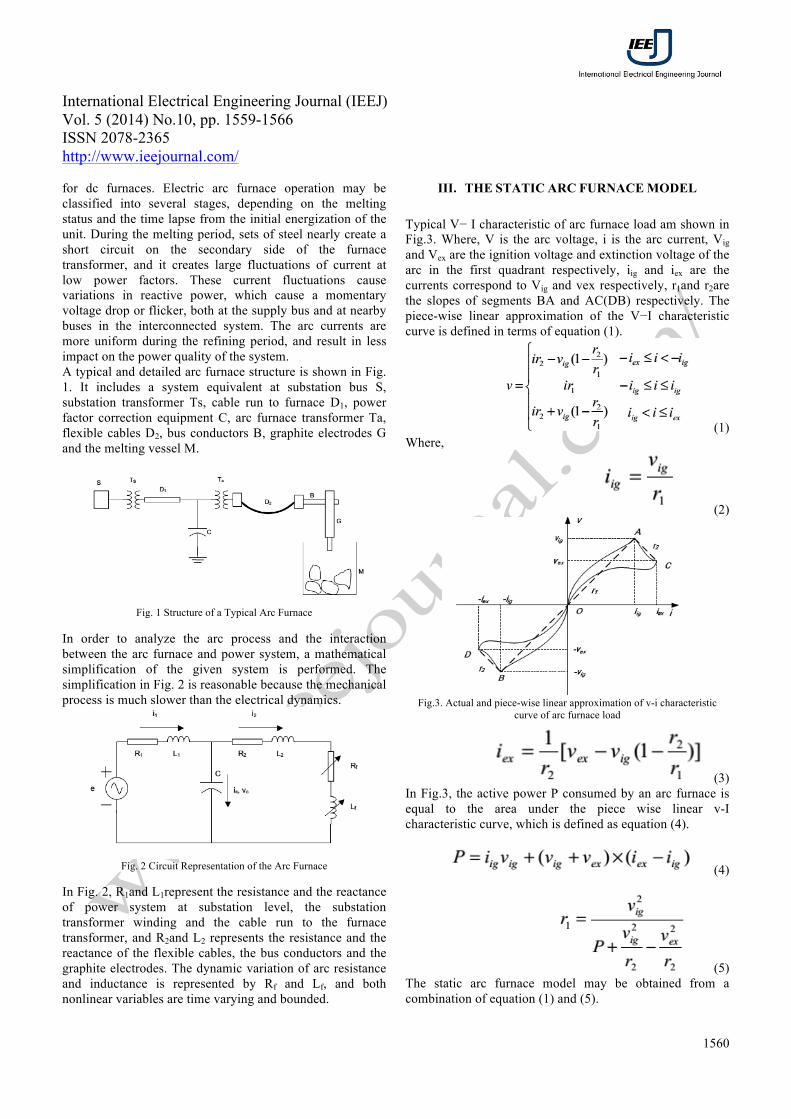
Fig.12 FFT Analysis of Electric Arc Furnace of Current waveform in
dynamic model Fig.12 shows the FFT Analysis of Electric Arc Furnace of Current waveform in dynamic model, attain 37.30%.
Fig.13 Matlab/Simulink Model of Proposed Chaotic Model of Arc Furnace
with DSTATCOM using Matlab/Simulink tool.
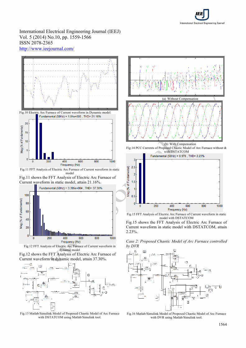
(a) Without Compensation
(b) With Compensation
Fig.14 PCC Currents of Proposed Chaotic Model of Arc Furnace without & with DSTATCOM
Fig.15 FFT Analysis of Electric Arc Furnace of Current waveform in static
model with DSTATCOM Fig.15 shows the FFT Analysis of Electric Arc Furnace of Current waveform in static model with DSTATCOM, attain 2.23%. Case 2: Proposed Chaotic Model of Arc Furnace controlled by DVR
Fig.16 Matlab/Simulink Model of Proposed Chaotic Model of Arc Furnace
with DVR using Matlab/Simulink tool.

International Electrical Engineering Journal (IEEJ) Vol. 5 (2014) No.10, pp. 1559-1566 ISSN 2078-2365 http://www.ieejournal.com/
1565
Pavani and Devi Improved Performance of Chaotic Model of AC Electric Arc Furnace Using Unified Power Quality Conditioner
(a) Without DVR
0 0.01 0.02 0.03 0.04 0.05 0.06 0.07 0.08 0.09 0.1-500
-400
-300
-200
-100
0
100
200
300
400
500
Time (secs)
Volta
ge (v
olts)
DVR output Voltage
(b) With DVR
Fig.17 PCC Voltages of Proposed Chaotic Model of Arc Furnace without & with DVR
Case 3: Proposed Chaotic Model of Arc Furnace controlled by UPQC
Fig.18 Matlab/Simulink Model of Proposed Chaotic Model of Arc Furnace
with UPQC using Matlab/Simulink tool.
0 0.02 0.04 0.06 0.08 0.1 0.12 0.14 0.16 0.18 0.2-1
-0.5
0
0.5
1x 10
5
time(sec)
volta
ge(V
)
0 0.02 0.04 0.06 0.08 0.1 0.12 0.14 0.16 0.18 0.2-100
-50
0
50
100
time(sec)
curr
ent(
ampe
res)
Fig.19 Source Voltage & Current of Proposed Chaotic Model of Arc
Furnace with UPQC
0 0.02 0.04 0.06 0.08 0.1 0.12 0.14 0.16 0.18 0.2-400
-200
0
200
400
time(sec)
voltage(V)
0 0.05 0.1 0.15 0.2 0.25 0.3 0.35 0.4 0.45 0.5-400
-200
0
200
400
time(sec)
current(Amperes)
Fig.20 Load Voltage & Current of Proposed Chaotic Model of Arc Furnace
with UPQC
Fig.21 Shunt Compensation Voltage & Current of Proposed Chaotic Model
of Arc Furnace with UPQC
Fig.22 Series Compensation Voltage & Current of Proposed Chaotic Model
of Arc Furnace with UPQC VII. CONCLUSION
UPQC topology has been proposed in this paper which has the capability to compensate voltage sags, voltage swells and current harmonics at the load. A chaotic arc furnace model for power quality studies is presented by using back-back connection of DVR & DSTATCOM to regulate the power quality concerns, which is not only useful for harmonic study, but also useful for flicker study. Where the dynamic arc furnace model is obtained using the chaotic signal to modulate the static arc voltage, the chaotic signal is generated via the asymmetric nonlinear Chua’s circuit.
REFERENCES [1] G. Manchur, and C. C. Erven, “Development of a model for predicting flicker from electric arc furnaces,” IEEE Trans. on Power Delivery, vol.7, pp.416-426, Jan. 1992. [2] C. B. Rafel, and G. Tomas, “Identification and modeling of a three phase arc furnace for voltage disturbance simulation,” IEEE Trans. on Power Delivery, vol.12, pp.1812-1817, Oct. 1997. [3] G. C. Montanari, M. Loggini, and A. Cavallini, “Arc-furnace model for the study of flicker compensation in electrical networks,” IEEE Trans. on Power Delivery, vol.9, pp.2026-2033, Oct. 1994. [4] S. Varadan, E. B. Makram, and A. A. Girgis, “A new time domain voltage source model for an arc furnace using EMTP,” IEEE Trans. on Power Delivery, vol.11, pp.1685-1691, July 1996. [5] J. Wang, M. Lin, and X. Y. Chen, “Modeling and simulation of AC arc furnace for dynamic power quality Studies,” Transactions of China Electro technical Society, vol.18, pp.53-58, Jun. 2003 (in Chinese).

International Electrical Engineering Journal (IEEJ) Vol. 5 (2014) No.10, pp. 1559-1566 ISSN 2078-2365 http://www.ieejournal.com/
1566
Pavani and Devi Improved Performance of Chaotic Model of AC Electric Arc Furnace Using Unified Power Quality Conditioner
[6] J. G. Mayordomo, L. F. Beites, and R. Asensi, “A new frequency domain arc furnace model for iterative harmonic analysis,” IEEE Trans. on power delivery, vol.12, pp.1771-1778, Oct. 1997. [7] B. R. Qi, and X. N. Xiao, “Modeling and simulation of an arc furnace for voltage fluctuation investigation,” Transactions of China Electro technical Society, vol.15, pp.31-35, Jun. 2000 (in Chinese). [8] P. A. M. Anxo, and M. P. Donsion, “An improved time domain arc furnace model for harmonic analysis,” IEEE Trans. on Power Delivery, vol.19, pp.367-373, Jan. 2004. [9] X. H. Liu, G. Zhao, and J. J. Yu, “Simulations on the impaction in power supply network caused by the nonlinear characteristic of electric arc furnace System,” Proceedings of the CSEE, vol.24, pp.30-34, Jun. 2004 (in Chinese). [10] X. D. Lu, and X. H. Liu, “Simulations on the impact of electrode regulator on the voltage fluctuation,” Proceedings of the CSEE, vol.26, pp.95-100, Apr. 2006 (in Chinese).