Embed Size (px)
Citation preview
14 IEEE TRANSACTIONS ON ROBOTICS, VOL. 30, NO. 1, FEBRUARY 2014
Improved Kinematic Models for Two-Link HelicalMicro/Nanoswimmers
Ahmet Fatih Tabak, Member, IEEE, and Serhat Yesilyurt, Senior Member, IEEE
Abstract—Accurate prediction of the 3-D trajectories of mi-cro/nanoswimmers is a key element to achieve high precision mo-tion control in therapeutic applications. Rigid-body kinematics ofsuch robotic systems is dominated by viscous forces. The inducedflow field around a two-link swimmer is investigated with a vali-dated computational fluid dynamics model. Force-free-swimmingconstraints are employed in order to simulate motion of bacteria-like swimmers in viscous medium. The fluid resistance exerted onthe body of the swimmer is quantified by an improved resistancematrix, which is embedded in a validated resistive force theorymodel, based on a complex-impedance approach. Parametric stud-ies confirmed that the hydrodynamic interaction between body andtail are of great importance in predicting the trajectories for suchsystems.
Index Terms—Biological cells, biomechatronics, fluidic mi-crosystems, hydrodynamics, numerical models, robot kinematics,velocity measurement.
I. INTRODUCTION
SWIMMING micro- and nanorobots in the literature arepresented as the candidates of minimal-invasive surgery
tools to handle high precision therapeutic operations such asretina repair [1], [2]. Based on observations on bacteria andspermatozoa, and via some macro and microscale experiments,propulsion mechanisms of natural microswimmers are estab-lished as viable actuation means for motile autonomous swim-ming microrobots [3]–[10]. Propulsion mechanisms of bacteriaand spermatozoa are based on wave propagation carried out byslender tail structures that are actuated by nanoscale motors [11].The motivation of this study is to identify the role of hydrody-namic interactions (HI) between body and tail on the effectivedrag force and rigid-body kinematics of bacteria species, and topresent modeling tools that improve the predictability of swim-ming trajectories of bacteria, which are to be incorporated incybernetic micro/nanorobotic systems as the means of propul-
Manuscript received March 24, 2013; revised August 5, 2013; acceptedSeptember 1, 2013. Date of publication September 30, 2013; date of currentversion February 3, 2014. This paper was recommended for publication byAssociate Editor A. Ferreira and Editor B. J. Nelson upon evaluation of thereviewers’ comments.
A. F. Tabak was with the Department of Mechatronics Engineering, Faculty ofEngineering and Natural Sciences, Sabanci University, 34956 Istanbul, Turkey.He is now with the Department of Mechatronics Engineering, Faculty of En-gineering and Design, Istanbul Commerce University, 34840 Istanbul, Turkey(e-mail: [email protected]).
S. Yesilyurt is with the Department of Mechatronics Engineering, Faculty ofEngineering and Natural Sciences, Sabanci University, 34956 Istanbul, Turkey(e-mail: [email protected]).
Color versions of one or more of the figures in this paper are available onlineat http://ieeexplore.ieee.org.
Digital Object Identifier 10.1109/TRO.2013.2281551
sion and navigation solving key problems such as energy supplyto artificial bioinspired swimmers. In that regard, E. Coli speciesare considered ideal examples of nanoscale devices [12].
A. Literature Review
Experimental work is carried out to manufacture rotary mo-tors in microdimensions [13]; however, the size and complexityof the bacterial motor [14] are the bottlenecks in construction ofa working replica, which compel researchers to execute artificialmeans of actuation [4], [8], [9] in order to achieve untetheredbioinspired microswimming.
In order to mimic natural swimmers, different actuation mech-anisms are employed: generating planar waves driven by exter-nal magnetic fields on an artificial magnetic tail attached to a redblood cell [4], employing dedicated dc motors to rotate helicaltails in order to control the motion of the bioinspired robot [8],or rotating the magnetic body of single-link helical swimmerswith magnetic fields driven by Helmholtz coils in order to gen-erate screw-like motion in viscous fluids [9], [10]. However, theenergy efficiency of such artificial systems is actually lower thanthat of the bacterial motor [15].
As another strategy, some bacteria species are consideredthe controllable means of actuation or propulsion for a vari-ety of microsystems provided that given proper conditions andincentives they already possess the capability of maneuveringthemselves [16]. One likely use for cybernetic microsystems iscarrying out therapeutic operations in living tissue; by means ofeither controlling a single bacterium as a nanorobot or using thebacterium cell as an integral part in microfluidic microsystemsfor transport and actuation purposes [17], [18].
The possibility of moving objects via natural swimmers thatemploy a bacterial motor is experimentally studied with groupsof S. Marcescens specimens attached to a cargo [19]. The au-thors investigated the propulsive forces, towing velocity andadherence durability in time. Martel [20] studied controlling theswimming direction of a magnetotactic bacteria (MTB) species,i.e., M. Gryphiswaldense, by inducing external magnetic fields,which in turn incorporates bacterial swimming with computercontrol. It is observed that the selected specimens follow the in-duced magnetic field lines. Martel et al. [21] manipulated singlebeads of 3 μm as cargo by controlling the velocity of individualMTBs. They further reported that reaching velocities faster than100 μm/s in magnitude is achievable [21]. Furthermore, build-ing blocks 80 μm in length, are piled over as in a 2-D pyramidby MTBs to demonstrate microassembly with bacteria [22].
Moreover, Uenoyama and Mitada [23] demonstrated that itis possible to neutralize a living natural microswimmer, e.g.,M. Mobile, to eliminate toxic side effects, while keeping the
1552-3098 © 2013 IEEE. Personal use is permitted, but republication/redistribution requires IEEE permission.See http://www.ieee.org/publications standards/publications/rights/index.html for more information.
TABAK AND YESILYURT: IMPROVED KINEMATIC MODELS FOR TWO-LINK HELICAL MICRO/NANOSWIMMERS 15
cell wall and bacterial motor intact. They confirmed that, with aseries of chemicals introduced in the environment, the bacterialmotor can be reactivated. Experimental studies are reported ontriggering and controlling the rotation rate of the flagella by in-troducing ions and chemicals to directly intervene the operationof the bacterial motor of certain species [24], [25]. An additionalreported method of bacterial maneuvering is an application ofsmall electric currents to change the speed and direction of wavepropagation [26]. The ability to control the swimming velocityand direction of natural micro/nanoswimmers indicates the needfor reliable real-time analytical models.
Comprehensive mathematical models on the propulsion ofmicroorganisms have been around for over 60 years. Han-cock [27], using the slender body theory (SBT), formulated theresistive force theory (RFT) for particles undergoing quasi-staticrigid-body motions in low Reynolds number viscous flows. Inthe RFT method, fluid force vector acting on a moving objectis linearly proportional to the rigid-body velocity vector rela-tive to the stationary fluid. However, the RFT model leads toomission of body–tail interactions: resistive force coefficientsare based on local translations of slender tails [28], [29] andrigid-body motions of isolated bodies with well-known geome-tries [30], [31].
Keller and Rubinow [32] presented a total six degrees-of-freedom (dof) analytical model for natural microswimmers andpointed out that the local fluid resistance on a moving and de-forming object of arbitrary shape is effected by the entire in-duced flow field. De la Torre and Bloomfield [33] modeled arepresentative microswimmer as a series of spherical bodiesand studied the local effects of body–tail interactions on therotating tail by HI tensors. The authors concluded that the localhydrodynamic forces acting on the tail differ dramatically nearthe joint between body and tail due to the cross interactions.Johnson [34] discussed that the SBT method analysis of heli-cal swimmers presents nonzero lateral forces based on the HIsbetween swimmer’s body and tail. Watari and Larson [35] dis-cussed that the instantaneous flow field induced around a naturalswimmer demonstrates transient behavior and the time averageof the flow-field strength is smaller than its instantaneous mag-nitude. The authors added that the hydrodynamic force on theswimmer’s body is also influenced by induced flow fields. Theaforementioned conclusions point out that the stationary fluidassumption is not accurate in the calculation of the drag forceon the body.
Phan-Thien et al. [36] used the boundary-element method(BEM) to solve Stokes equation and studied the effects of thegeometry of the helical tail and the geometry of a spheroid bodyon the forward velocity and hydrodynamic efficiency of themicroswimmers. The authors discussed that the interaction be-tween the two links decreases forward swimming velocity andthe hydrodynamic efficiency of the swimmer. Ramia et al. [37]carried out BEM analysis to obtain the motion of spheres witha single rotating helical tail that is swimming in unbounded andbounded fluids. They studied the effect of HI on the overallpropulsive and resistive behavior of the helical tail separatelyin detail. In both studies, the main focus was on the forces thatare acting on the helical tail, swimming velocities, and hydro-
dynamic efficiency. It was concluded that the overall forwarddrag resistance of the swimmer increases with HIs.
Hydrodynamic models are of great importance because theyare also used in the determination of geometric properties andswimming trajectories for bacteria and spermatozoa species.The RFT approach is employed to determine the high-orderplane-wave form and to predict the motion of spermatozoacells in full motion based on observations [38]. Planar waveactuation is more advantageous to investigate by a high-speed-and-resolution camera since the resultant motion is typicallyconfined to the plane in which wave propagation takes place.However, tracking or observation of a bacterial cell in the thirddimension proposes a more challenging task due the dimen-sions, thus observations on cells presented in the literature aremostly limited to constrained plane motions [39], [40], althoughthere exists recent 3-D-tracking examples for protists [41], [42].Furthermore, 3-D trajectory construction studies are carried outwith solutions of stochastic differential equations based on theobservations on 2-D motion [43].
In addition to trajectory construction studies, the RFT is for-merly employed in order to predict the propulsive forces gener-ated by a number of artificial helical swimmers in nanometer-,micrometer-, millimeter-, and centimeter-scale subject to var-ious swimming conditions [44]–[49]. In a recent study, Ma-honey et al. [47] utilized an RFT-based hydrodynamic modelin order to predict necessary hydrodynamic forces in real-timeand effectively control the velocity of a magnetically actuatedmillimeter-length helical swimmer with gravity compensationin an open-loop control scheme.
Furthermore, previous studies confirm that, as long as theinertial forces are significantly dominated by the viscous forceswithin the fluid, i.e., Re < 0.1, the RFT approach is capable ofpredicting the time-averaged spatial velocities of an untetheredswimmer, with an acceptable error, regardless of its actual size[48]–[50]. However, it is verified by Higdon [51] that powerconsumption of a microswimmer is miscalculated by the RFTmethod.
B. Main Contributions
Numerical studies conclude that the HI between the bodyand helical tail is significant; but, a comprehensive analysisto quantify the drag force on the body in the presence of anactuated tail is not presented in the literature to the best of ourknowledge. Furthermore, the lateral oscillations of the bacteriaare not considered kinematically in analytical models so far.Given the complicated shape of the body–tail assembly andthe HIs between them, conventional diagonal resistance matrixapproach for isolated axisymmetric rigid particles in viscousflows is insufficient to account for the lateral oscillations ofbacteria.
In this study, a computational fluid dynamics (CFD) model,which is validated with vertical in-channel swimming experi-ments on centimeter-scale bacteria-like robots, is employed toexamine the 4-dof motion of a biomimetic swimmer comprisedof a rotating rigid helical tail and a spherical body, which areheld together with a revolute joint. Experiments are designed
16 IEEE TRANSACTIONS ON ROBOTICS, VOL. 30, NO. 1, FEBRUARY 2014
to eliminate all known physical phenomena, e.g., forces suchas Brownian noise, which is of importance in nanoscale [12],gravitational pull, and lubricated friction, but far-field HIs thatare acting on the wet surfaces.
Initially, using the CFD model, we studied swimming veloc-ities with induced flow fields and obtained the hydrodynamicforces that are acting on the swimmer surface. Subsequently,we employed complex-impedance analysis in the RFT modelto introduce HI coefficients, which are embedded in the resis-tance matrix, to compensate for the flow-field interactions andpredict the instantaneous fluid resistance accurately for viscousswimming conditions regardless of the dimensions of bacteriaor bacteria-like robots. It is verified that modified resistancematrix predicts time-dependent fluid forces with superior pre-cision. Moreover, the effect of the body and tail geometry isstudied concluding that the HI is vastly dominated by the latterdetermining the swimming trajectory.
II. METHODOLOGY
A. Resistive Force Theory Model
The RFT approach is well documented in [11], [27]–[29],and [32]: in the Reynolds number or creeping flow regime, thefluid resistance Fj , i.e., the drag force, which is acting on themoving particle along an arbitrary axis is linearly proportionalto the velocity Vj of that particle. This is a valid approach topredicting the drag force per unit length on a deformed slenderbody submerged in a highly viscous fluid with Re < 0.1 [28],[29]. Furthermore, the total fluid drag on a submerged particlefreely moving in a viscous flow should add up to zero [52].Using these two linear relationships, one can write down theequation of motion for a two-link helical swimmer as follows:
Fb + Ft = 0 (1)
F{b,t} = −B{b,t}V{b,t} (2)
where B denotes the fluid resistance matrix for each link, namelybody and tail denoted by the subscripts “b” and “t,” respectively.
Tail resistance Bt is obtained integrating the local force co-efficients, which are projected onto the lab coordinates withthe local frame rotations, over the actual chord length � in thefollowing fashion:
Bt =∫
�
[RCRT −RCRT S
SRCRT −SRCRT S
]d� (3)
where R is the rotation matrix between local Frenet–Serretframes and swimmer frame [53] [see Fig. 1(a)], S is the skew-symmetric matrix corresponding to the cross product with thetime-dependent position vector P, C signifies the local fluid re-sistance matrix of the tail, and the superscript “T ” denotes thematrix transpose.
The position vector on a rotating left-handed helical tail withwavelength λ, angular rotation ω, and local amplitude B(x) foran arbitrary x-position can be specified by
P = [x B(x) cos(ωt − kx) B(x) sin(ωt − kx) ]T . (4)
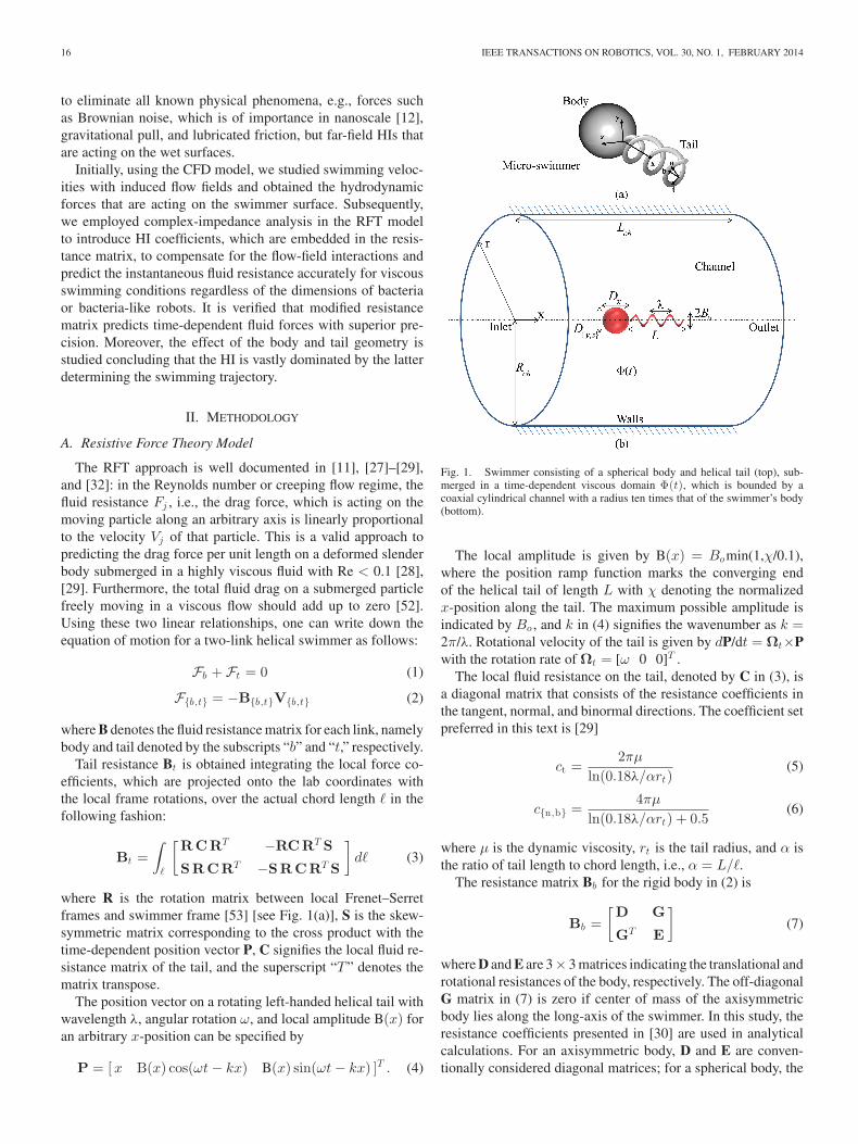
Fig. 1. Swimmer consisting of a spherical body and helical tail (top), sub-merged in a time-dependent viscous domain Φ(t), which is bounded by acoaxial cylindrical channel with a radius ten times that of the swimmer’s body(bottom).
The local amplitude is given by B(x) = Bomin(1,χ/0.1),where the position ramp function marks the converging endof the helical tail of length L with χ denoting the normalizedx-position along the tail. The maximum possible amplitude isindicated by Bo , and k in (4) signifies the wavenumber as k =2π/λ. Rotational velocity of the tail is given by dP/dt = Ωt×Pwith the rotation rate of Ωt = [ω 0 0]T .
The local fluid resistance on the tail, denoted by C in (3), isa diagonal matrix that consists of the resistance coefficients inthe tangent, normal, and binormal directions. The coefficient setpreferred in this text is [29]
ct =2πμ
ln(0.18λ/αrt)(5)
c{n,b} =4πμ
ln(0.18λ/αrt) + 0.5(6)
where μ is the dynamic viscosity, rt is the tail radius, and α isthe ratio of tail length to chord length, i.e., α = L/�.
The resistance matrix Bb for the rigid body in (2) is
Bb =[D G
GT E
](7)
where D and E are 3× 3 matrices indicating the translational androtational resistances of the body, respectively. The off-diagonalG matrix in (7) is zero if center of mass of the axisymmetricbody lies along the long-axis of the swimmer. In this study, theresistance coefficients presented in [30] are used in analyticalcalculations. For an axisymmetric body, D and E are conven-tionally considered diagonal matrices; for a spherical body, the
TABAK AND YESILYURT: IMPROVED KINEMATIC MODELS FOR TWO-LINK HELICAL MICRO/NANOSWIMMERS 17
diagonals of D are equal to 3πμDx and the diagonals of E areequal to πμD3
x [30].Rearranging the equation of motion, assuming that there are
no other external stimuli on the system, one finds the velocityvector of the swimmer, which is denoted by the subscript “s” inthe left-hand side, in the form[
V
Ω
]s
= −BTs Bt
[0
Ω
]t
(8)
where Bs is the effective fluid resistance matrix of the entireswimmer [48], [49]. Furthermore, one may impose “0” on allelements of any row and column in BT
s to eliminate translationalor rotational motion along a desired axis.
B. Computational Fluid Dynamics Model
Fig. 1(b) demonstrates the microswimmer in the time-dependent fluidic domain Φ(t) bounded by the cylindrical chan-nel. Consider a spherical body with a helical tail. One end ofthe helical tail is converging to its long axis, where the revolutejoint is placed. This geometric design is a valid representationfor some bacteria species [50]. The spherical body and a helicaltail are apart from each other with the tail radius in order toeliminate discontinuity under angular velocity boundary condi-tions. It is considered that both body and helical tail are neutrallybuoyant with the surrounding medium, which is bounded by acylindrical channel. The channel diameter is ten times that ofthe sphere diameter to eliminate the wall effects [54], and theswimmer is placed coaxially, as shown in Fig. 1(b).
Time-dependent incompressible Navier–Stokes equationsgovern the induced flow field in Φ(t) and are subject to conti-nuity as follows:
ρ
(∂U∂t
+ (U − xmesh) · ∇U)
= −∇p + μ∇2U (9)
∇ · U = 0. (10)
Here, U and xmesh are respective fluid and mesh velocityvectors computed in Φ(t), ρ is the fluid density, and p denotesthe hydrostatic pressure. Mesh of the swimmer is handled witharbitrary-Lagrangian-Eulerian (ALE) deformation in order toincorporate motion of swimmer boundaries with respect to sta-tionary channel walls [55].
Zero-velocity and zero-pressure initial conditions are set for(9) and (10) initially, whereas no-slip boundary condition isimposed on stationary channel walls at all times. Normal stressvectors are set to zero at channel’s inlet and outlet to achieveopen-flow boundary condition [56].
Position vector on the rotating left-handed helical tail is sig-nified with a modified local amplitude function as B(x) =Bomin(1, χ/0.1)min(1, f /4t), where f denotes the actuationfrequency of the tail. The local amplitude increases with a timeramp to ensure smooth transition of the fully developed rotatinghelical profile for the surrounding mesh.
Resultant body rotation rate vector, due to conservation ofangular momentum, is given as Ωb = [Ωx 0 0]T , and thecorresponding fluid and mesh velocity boundary conditions onthe surfaces of body, i.e., Ψb , and on the surfaces of tail, i.e.,
Ψt , are given respectively by
U = V + Ωb × xs
u = V
}⇐ xs ∈ Ψb (11)
U = u =dPdt
+ V ⇐ xs ∈ Ψt (12)
where xs signifies the position vector of an arbitrary point onthe surface of the swimmer with respect to its center of mass.
Resultant swimming velocity vectors are computed withforce-free-swimming constraints: in creeping flows, the fluidresistance on the entire surface of a self propelling swimmeradds up to zero [52]. Thus, the total instantaneous fluid forceis set to zero in order to obtain rigid-body velocities satisfyingzero-net-force and zero-net-torque constraints. The respectiveconstraint equations for the hydrodynamic force and hydrody-namic torque that are on the entire surface of the swimmer arespecified as follows:
∫Ψ b +Ψ t
[−pI + τ ]n dA = 0 (13)
∫Ψ b +Ψ t
xs × [−pI + τ ]n dA = 0. (14)
Here, A denotes the surface area in contact with the viscousfluid, local surface normal vector is signified by n, and τ standsfor the viscous stress tensor. Initial conditions are V = 0 andΩb = 0; the constraint equations are solved at each time incre-ment based on the fluid resistance corresponding to the resultantrigid-body velocities of the preceding time-step combined withthe tail rotation already in progress.
The last two rows of the constraints (13) and (14) are ex-cluded in the CFD model and the lateral rigid-body rotations,i.e., yaw and pitch, are eliminated. Omission of lateral rotationsof the swimmer frame in the channel frame greatly simplifies themesh deformation in Φ(t) eliminating numerical convergenceissues and rotation matrix calculations between the two frames.Furthermore, Hyon et al. [57] studied wiggling trajectories ofbacteria and concluded that lateral rotations of the swimmer areobserved clearly when the tail is not collinear with the symme-try axis. Otherwise, relatively straight trajectories are observedowing to much faster rate of rotation of the tail compared withthe body [57].
C. Experiments
In this study, a set of in-channel experiments, which are re-ported in detail elsewhere [49], are used to validate the CFDmodel. A centimeter-scale biomimetic robot comprising of acylindrical body and a rigid helical tail, which is actuated by adedicated dc-motor, is used in experiments [see Fig. 2(a)]. Oneend of the rigid tail is deformed with a hyperbolic-tangent pro-file and attached to the rotor of the dc motor, which constitutesthe revolute joint allowing body and tail to rotate in oppositedirections in order to mimic swimming of a bacterium with asingle helical tail [50].
18 IEEE TRANSACTIONS ON ROBOTICS, VOL. 30, NO. 1, FEBRUARY 2014
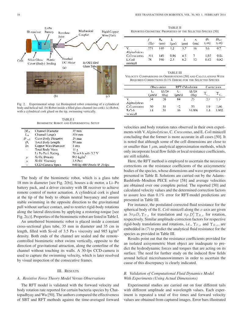
Fig. 2. Experimental setup. (a) Bioinspired robot consisting of a cylindricalbody and helical tail. (b) Robot inside a filled glass channel (no cork). (c) Robot,with a cylindrical cork glued on the tip, swimming vertically.
TABLE IBIOMIMETIC ROBOT AND EXPERIMENTAL SETUP
The body of the biomimetic robot, which is a glass tube18 mm in diameter [see Fig. 2(b)], houses a dc motor, a Li–Pobattery pack, and a driver circuitry with IR receiver to achieveremote control of motor actuation. A cylindrical cork is gluedat the tip of the body to obtain neutral buoyancy and ensurestable swimming in the opposite direction to the gravitationalpull without surface contact, and to restrict rigid-body rotationsalong the lateral directions by applying a restoring-torque [seeFig. 2(c)]. Properties of the biomimetic robot are listed in Table I.
An untethered biomimetic robot is placed inside a constantcross-sectional glass tube, 35 mm in diameter and 35 cm inlength, filled with Si-oil of 3.5 Pa·s viscosity and 985 kg/m3
density. Both ends of the channel are sealed and the remote-controlled biomimetic robot swims vertically, opposite to thedirection of gravitational attraction, along the centerline of thechannel without touching its walls. A 30-fps CCD-camera isused to capture the swimming velocity, which is later resolvedby visual inspection of the consecutive frames.
III. RESULTS
A. Resistive Force Theory Model Versus Observations
The RFT model is validated with the forward velocity andbody rotation rate reported for certain bacteria species by Chat-topadhyay and Wu [50]. The authors compared the effectivenessof SBT and RFT methods against the time-averaged forward
TABLE IIREPORTED GEOMETRIC PROPERTIES OF THE SELECTED SPECIES [50]
TABLE IIIVELOCITY COMPARISONS ON OBSERVATIONS [50] AND CALCULATIONS WITH
REQUIRED CORRECTIONS (0.1% ERROR) FOR THE SELECTED SPECIES
velocities and body rotation rates observed in their own experi-ments with V. Alginolyticus, C. Crescentus, and E. Coli minicellconcluding that the former is more accurate in all cases [50]. Itis noted that although some of the cell dimensions are close toor smaller than 1 μm, analytical approximation methods, whichonly incorporate local flow fields or local resistance coefficients,are still reliable.
Here, the RFT method is employed to ascertain the necessarycorrections on the resistance coefficients of the axisymmetricbodies of the species, whose dimensions and wave properties arepresented in Table II. Solutions are carried out by the Adams–Bashforth–Moulton PECE solver [58] and average velocitiesare obtained over one complete period. The reported [50] andcalculated velocity values and the determined correction factorsto assure less than 0.1% error for RFT-model predictions arepresented in Table III.
For instance, the postulated corrected fluid resistance for thespherical body of the E. Coli minicell along the x-axis are givenas 3πμDxΥT ,x for translation and πμD3
x ΥR,x for rotation,respectively. Similar amplitude-correction factors for respectiverigid-body translations and rotations, i.e., ΥT ,x and ΥR,x , areembedded in (7) to predict the analytical fluid resistance for thespecies as provided in Table III.
Results point out that the resistance coefficients provided foran isolated axisymmetric blunt object are inadequate to pre-dict the hydrodynamic forces and torques that are acting on itssurface. The need for further study on the induced flow fieldsaround helical micro/nanoswimmers in order to ascertain thecause of this discrepancy is clearly indicated.
B. Validation of Computational Fluid Dynamics ModelWith Experiments (Using Actual Dimensions)
Experimental studies are carried out on four different tailswith different amplitude and wavelength values. Each exper-iment is repeated a total of five times and forward velocityvalues are obtained from captured images. Error bars illustrated
TABAK AND YESILYURT: IMPROVED KINEMATIC MODELS FOR TWO-LINK HELICAL MICRO/NANOSWIMMERS 19
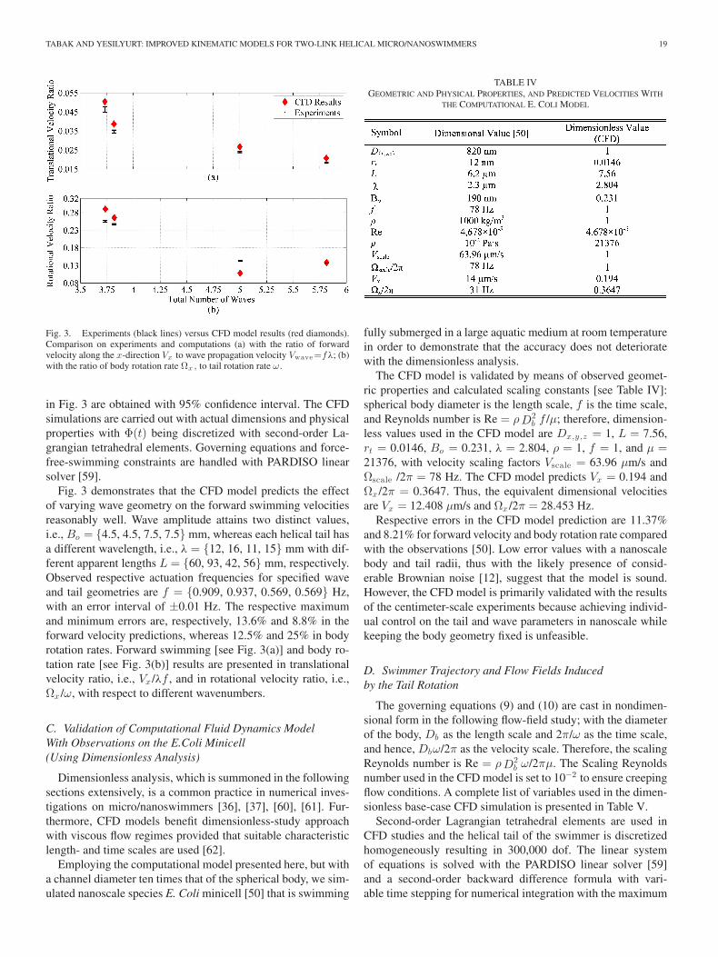
Fig. 3. Experiments (black lines) versus CFD model results (red diamonds).Comparison on experiments and computations (a) with the ratio of forwardvelocity along the x-direction Vx to wave propagation velocity Vwave=fλ; (b)with the ratio of body rotation rate Ωx , to tail rotation rate ω.
in Fig. 3 are obtained with 95% confidence interval. The CFDsimulations are carried out with actual dimensions and physicalproperties with Φ(t) being discretized with second-order La-grangian tetrahedral elements. Governing equations and force-free-swimming constraints are handled with PARDISO linearsolver [59].
Fig. 3 demonstrates that the CFD model predicts the effectof varying wave geometry on the forward swimming velocitiesreasonably well. Wave amplitude attains two distinct values,i.e., Bo = {4.5, 4.5, 7.5, 7.5} mm, whereas each helical tail hasa different wavelength, i.e., λ = {12, 16, 11, 15} mm with dif-ferent apparent lengths L = {60, 93, 42, 56} mm, respectively.Observed respective actuation frequencies for specified waveand tail geometries are f = {0.909, 0.937, 0.569, 0.569} Hz,with an error interval of ±0.01 Hz. The respective maximumand minimum errors are, respectively, 13.6% and 8.8% in theforward velocity predictions, whereas 12.5% and 25% in bodyrotation rates. Forward swimming [see Fig. 3(a)] and body ro-tation rate [see Fig. 3(b)] results are presented in translationalvelocity ratio, i.e., Vx /λf , and in rotational velocity ratio, i.e.,Ωx /ω, with respect to different wavenumbers.
C. Validation of Computational Fluid Dynamics ModelWith Observations on the E.Coli Minicell(Using Dimensionless Analysis)
Dimensionless analysis, which is summoned in the followingsections extensively, is a common practice in numerical inves-tigations on micro/nanoswimmers [36], [37], [60], [61]. Fur-thermore, CFD models benefit dimensionless-study approachwith viscous flow regimes provided that suitable characteristiclength- and time scales are used [62].
Employing the computational model presented here, but witha channel diameter ten times that of the spherical body, we sim-ulated nanoscale species E. Coli minicell [50] that is swimming
TABLE IVGEOMETRIC AND PHYSICAL PROPERTIES, AND PREDICTED VELOCITIES WITH
THE COMPUTATIONAL E. COLI MODEL
fully submerged in a large aquatic medium at room temperaturein order to demonstrate that the accuracy does not deterioratewith the dimensionless analysis.
The CFD model is validated by means of observed geomet-ric properties and calculated scaling constants [see Table IV]:spherical body diameter is the length scale, f is the time scale,and Reynolds number is Re = ρD2
b f /μ; therefore, dimension-less values used in the CFD model are Dx,y ,z = 1, L = 7.56,rt = 0.0146, Bo = 0.231, λ = 2.804, ρ = 1, f = 1, and μ =21376, with velocity scaling factors Vscale = 63.96 μm/s andΩscale /2π = 78 Hz. The CFD model predicts Vx = 0.194 andΩx /2π = 0.3647. Thus, the equivalent dimensional velocitiesare Vx = 12.408 μm/s and Ωx /2π = 28.453 Hz.
Respective errors in the CFD model prediction are 11.37%and 8.21% for forward velocity and body rotation rate comparedwith the observations [50]. Low error values with a nanoscalebody and tail radii, thus with the likely presence of consid-erable Brownian noise [12], suggest that the model is sound.However, the CFD model is primarily validated with the resultsof the centimeter-scale experiments because achieving individ-ual control on the tail and wave parameters in nanoscale whilekeeping the body geometry fixed is unfeasible.
D. Swimmer Trajectory and Flow Fields Inducedby the Tail Rotation
The governing equations (9) and (10) are cast in nondimen-sional form in the following flow-field study; with the diameterof the body, Db as the length scale and 2π/ω as the time scale,and hence, Dbω/2π as the velocity scale. Therefore, the scalingReynolds number is Re = ρD2
b ω/2πμ. The Scaling Reynoldsnumber used in the CFD model is set to 10−2 to ensure creepingflow conditions. A complete list of variables used in the dimen-sionless base-case CFD simulation is presented in Table V.
Second-order Lagrangian tetrahedral elements are used inCFD studies and the helical tail of the swimmer is discretizedhomogeneously resulting in 300,000 dof. The linear systemof equations is solved with the PARDISO linear solver [59]and a second-order backward difference formula with vari-able time stepping for numerical integration with the maximum
20 IEEE TRANSACTIONS ON ROBOTICS, VOL. 30, NO. 1, FEBRUARY 2014
TABLE VPARAMETERS FOR THE BASE-CASE CFD SIMULATION
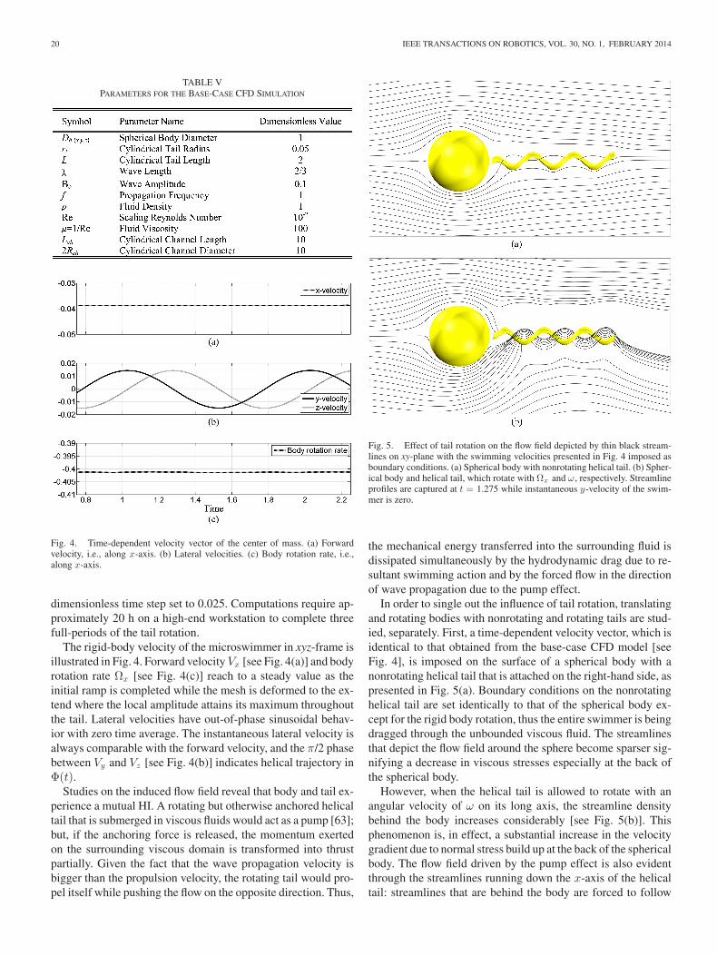
Fig. 4. Time-dependent velocity vector of the center of mass. (a) Forwardvelocity, i.e., along x-axis. (b) Lateral velocities. (c) Body rotation rate, i.e.,along x-axis.
dimensionless time step set to 0.025. Computations require ap-proximately 20 h on a high-end workstation to complete threefull-periods of the tail rotation.
The rigid-body velocity of the microswimmer in xyz-frame isillustrated in Fig. 4. Forward velocity Vx [see Fig. 4(a)] and bodyrotation rate Ωx [see Fig. 4(c)] reach to a steady value as theinitial ramp is completed while the mesh is deformed to the ex-tend where the local amplitude attains its maximum throughoutthe tail. Lateral velocities have out-of-phase sinusoidal behav-ior with zero time average. The instantaneous lateral velocity isalways comparable with the forward velocity, and the π/2 phasebetween Vy and Vz [see Fig. 4(b)] indicates helical trajectory inΦ(t).
Studies on the induced flow field reveal that body and tail ex-perience a mutual HI. A rotating but otherwise anchored helicaltail that is submerged in viscous fluids would act as a pump [63];but, if the anchoring force is released, the momentum exertedon the surrounding viscous domain is transformed into thrustpartially. Given the fact that the wave propagation velocity isbigger than the propulsion velocity, the rotating tail would pro-pel itself while pushing the flow on the opposite direction. Thus,
Fig. 5. Effect of tail rotation on the flow field depicted by thin black stream-lines on xy-plane with the swimming velocities presented in Fig. 4 imposed asboundary conditions. (a) Spherical body with nonrotating helical tail. (b) Spher-ical body and helical tail, which rotate with Ωx and ω, respectively. Streamlineprofiles are captured at t = 1.275 while instantaneous y-velocity of the swim-mer is zero.
the mechanical energy transferred into the surrounding fluid isdissipated simultaneously by the hydrodynamic drag due to re-sultant swimming action and by the forced flow in the directionof wave propagation due to the pump effect.
In order to single out the influence of tail rotation, translatingand rotating bodies with nonrotating and rotating tails are stud-ied, separately. First, a time-dependent velocity vector, which isidentical to that obtained from the base-case CFD model [seeFig. 4], is imposed on the surface of a spherical body with anonrotating helical tail that is attached on the right-hand side, aspresented in Fig. 5(a). Boundary conditions on the nonrotatinghelical tail are set identically to that of the spherical body ex-cept for the rigid body rotation, thus the entire swimmer is beingdragged through the unbounded viscous fluid. The streamlinesthat depict the flow field around the sphere become sparser sig-nifying a decrease in viscous stresses especially at the back ofthe spherical body.
However, when the helical tail is allowed to rotate with anangular velocity of ω on its long axis, the streamline densitybehind the body increases considerably [see Fig. 5(b)]. Thisphenomenon is, in effect, a substantial increase in the velocitygradient due to normal stress build up at the back of the sphericalbody. The flow field driven by the pump effect is also evidentthrough the streamlines running down the x-axis of the helicaltail: streamlines that are behind the body are forced to follow
TABAK AND YESILYURT: IMPROVED KINEMATIC MODELS FOR TWO-LINK HELICAL MICRO/NANOSWIMMERS 21
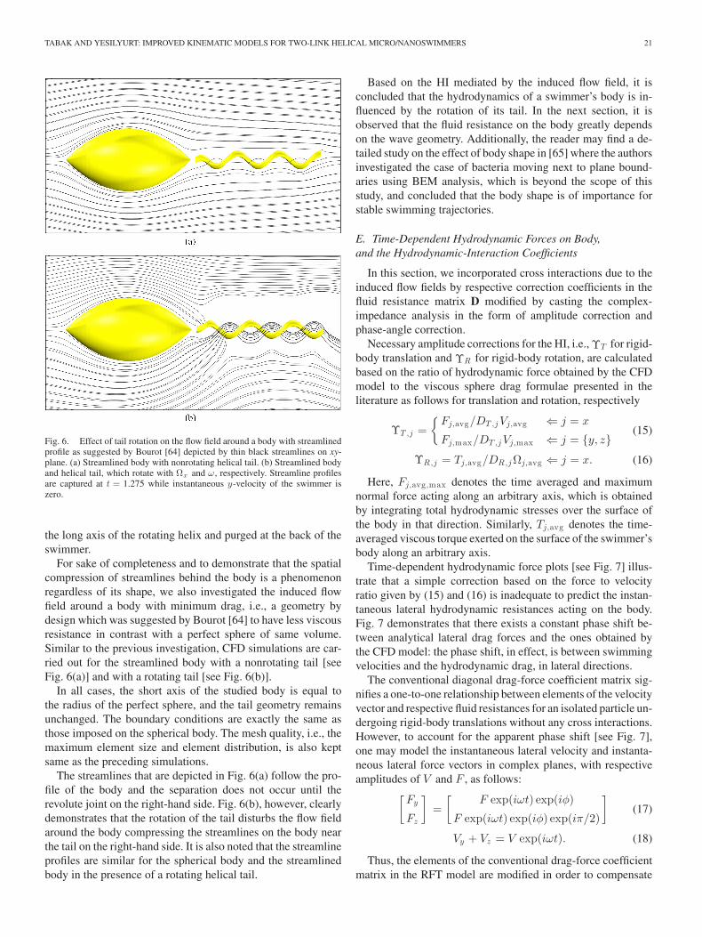
Fig. 6. Effect of tail rotation on the flow field around a body with streamlinedprofile as suggested by Bourot [64] depicted by thin black streamlines on xy-plane. (a) Streamlined body with nonrotating helical tail. (b) Streamlined bodyand helical tail, which rotate with Ωx and ω, respectively. Streamline profilesare captured at t = 1.275 while instantaneous y-velocity of the swimmer iszero.
the long axis of the rotating helix and purged at the back of theswimmer.
For sake of completeness and to demonstrate that the spatialcompression of streamlines behind the body is a phenomenonregardless of its shape, we also investigated the induced flowfield around a body with minimum drag, i.e., a geometry bydesign which was suggested by Bourot [64] to have less viscousresistance in contrast with a perfect sphere of same volume.Similar to the previous investigation, CFD simulations are car-ried out for the streamlined body with a nonrotating tail [seeFig. 6(a)] and with a rotating tail [see Fig. 6(b)].
In all cases, the short axis of the studied body is equal tothe radius of the perfect sphere, and the tail geometry remainsunchanged. The boundary conditions are exactly the same asthose imposed on the spherical body. The mesh quality, i.e., themaximum element size and element distribution, is also keptsame as the preceding simulations.
The streamlines that are depicted in Fig. 6(a) follow the pro-file of the body and the separation does not occur until therevolute joint on the right-hand side. Fig. 6(b), however, clearlydemonstrates that the rotation of the tail disturbs the flow fieldaround the body compressing the streamlines on the body nearthe tail on the right-hand side. It is also noted that the streamlineprofiles are similar for the spherical body and the streamlinedbody in the presence of a rotating helical tail.
Based on the HI mediated by the induced flow field, it isconcluded that the hydrodynamics of a swimmer’s body is in-fluenced by the rotation of its tail. In the next section, it isobserved that the fluid resistance on the body greatly dependson the wave geometry. Additionally, the reader may find a de-tailed study on the effect of body shape in [65] where the authorsinvestigated the case of bacteria moving next to plane bound-aries using BEM analysis, which is beyond the scope of thisstudy, and concluded that the body shape is of importance forstable swimming trajectories.
E. Time-Dependent Hydrodynamic Forces on Body,and the Hydrodynamic-Interaction Coefficients
In this section, we incorporated cross interactions due to theinduced flow fields by respective correction coefficients in thefluid resistance matrix D modified by casting the complex-impedance analysis in the form of amplitude correction andphase-angle correction.
Necessary amplitude corrections for the HI, i.e., ΥT for rigid-body translation and ΥR for rigid-body rotation, are calculatedbased on the ratio of hydrodynamic force obtained by the CFDmodel to the viscous sphere drag formulae presented in theliterature as follows for translation and rotation, respectively
ΥT ,j ={
Fj,avg/DT ,jVj,avg ⇐ j = x
Fj,max/DT ,jVj,max ⇐ j = {y, z}(15)
ΥR,j = Tj,avg/DR,jΩj,avg ⇐ j = x. (16)
Here, Fj,avg ,max denotes the time averaged and maximumnormal force acting along an arbitrary axis, which is obtainedby integrating total hydrodynamic stresses over the surface ofthe body in that direction. Similarly, Tj,avg denotes the time-averaged viscous torque exerted on the surface of the swimmer’sbody along an arbitrary axis.
Time-dependent hydrodynamic force plots [see Fig. 7] illus-trate that a simple correction based on the force to velocityratio given by (15) and (16) is inadequate to predict the instan-taneous lateral hydrodynamic resistances acting on the body.Fig. 7 demonstrates that there exists a constant phase shift be-tween analytical lateral drag forces and the ones obtained bythe CFD model: the phase shift, in effect, is between swimmingvelocities and the hydrodynamic drag, in lateral directions.
The conventional diagonal drag-force coefficient matrix sig-nifies a one-to-one relationship between elements of the velocityvector and respective fluid resistances for an isolated particle un-dergoing rigid-body translations without any cross interactions.However, to account for the apparent phase shift [see Fig. 7],one may model the instantaneous lateral velocity and instanta-neous lateral force vectors in complex planes, with respectiveamplitudes of V and F , as follows:
[Fy
Fz
]=
[F exp(iωt) exp(iφ)
F exp(iωt) exp(iφ) exp(iπ/2)
](17)
Vy + Vz = V exp(iωt). (18)
Thus, the elements of the conventional drag-force coefficientmatrix in the RFT model are modified in order to compensate
22 IEEE TRANSACTIONS ON ROBOTICS, VOL. 30, NO. 1, FEBRUARY 2014
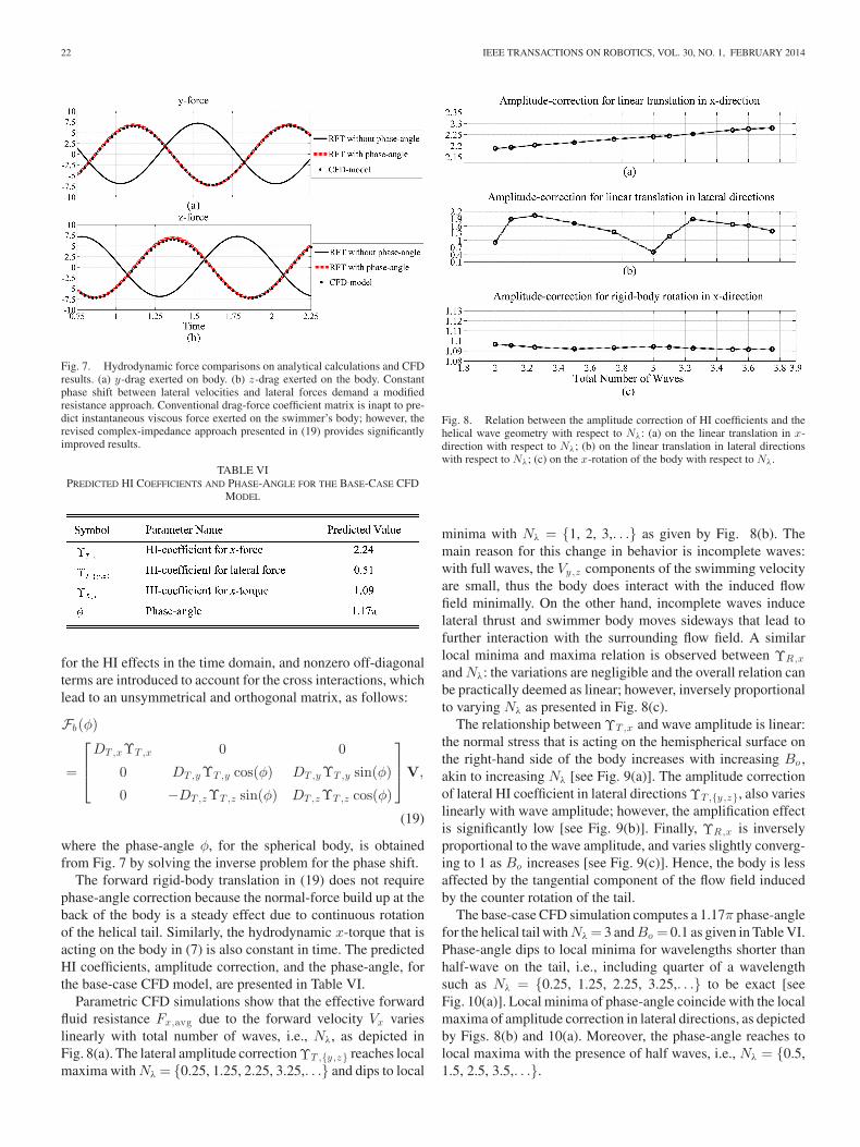
Fig. 7. Hydrodynamic force comparisons on analytical calculations and CFDresults. (a) y-drag exerted on body. (b) z-drag exerted on the body. Constantphase shift between lateral velocities and lateral forces demand a modifiedresistance approach. Conventional drag-force coefficient matrix is inapt to pre-dict instantaneous viscous force exerted on the swimmer’s body; however, therevised complex-impedance approach presented in (19) provides significantlyimproved results.
TABLE VIPREDICTED HI COEFFICIENTS AND PHASE-ANGLE FOR THE BASE-CASE CFD
MODEL
for the HI effects in the time domain, and nonzero off-diagonalterms are introduced to account for the cross interactions, whichlead to an unsymmetrical and orthogonal matrix, as follows:
Fb(φ)
=
⎡⎢⎣
DT ,xΥT ,x 0 0
0 DT ,yΥT ,y cos(φ) DT ,yΥT ,y sin(φ)
0 −DT ,zΥT ,z sin(φ) DT ,zΥT ,z cos(φ)
⎤⎥⎦V,
(19)
where the phase-angle φ, for the spherical body, is obtainedfrom Fig. 7 by solving the inverse problem for the phase shift.
The forward rigid-body translation in (19) does not requirephase-angle correction because the normal-force build up at theback of the body is a steady effect due to continuous rotationof the helical tail. Similarly, the hydrodynamic x-torque that isacting on the body in (7) is also constant in time. The predictedHI coefficients, amplitude correction, and the phase-angle, forthe base-case CFD model, are presented in Table VI.
Parametric CFD simulations show that the effective forwardfluid resistance Fx,avg due to the forward velocity Vx varieslinearly with total number of waves, i.e., Nλ, as depicted inFig. 8(a). The lateral amplitude correction ΥT ,{y ,z} reaches localmaxima with Nλ = {0.25, 1.25, 2.25, 3.25,. . .} and dips to local
Fig. 8. Relation between the amplitude correction of HI coefficients and thehelical wave geometry with respect to Nλ: (a) on the linear translation in x-direction with respect to Nλ; (b) on the linear translation in lateral directionswith respect to Nλ; (c) on the x-rotation of the body with respect to Nλ.
minima with Nλ = {1, 2, 3,. . .} as given by Fig. 8(b). Themain reason for this change in behavior is incomplete waves:with full waves, the Vy,z components of the swimming velocityare small, thus the body does interact with the induced flowfield minimally. On the other hand, incomplete waves inducelateral thrust and swimmer body moves sideways that lead tofurther interaction with the surrounding flow field. A similarlocal minima and maxima relation is observed between ΥR,x
and Nλ: the variations are negligible and the overall relation canbe practically deemed as linear; however, inversely proportionalto varying Nλ as presented in Fig. 8(c).
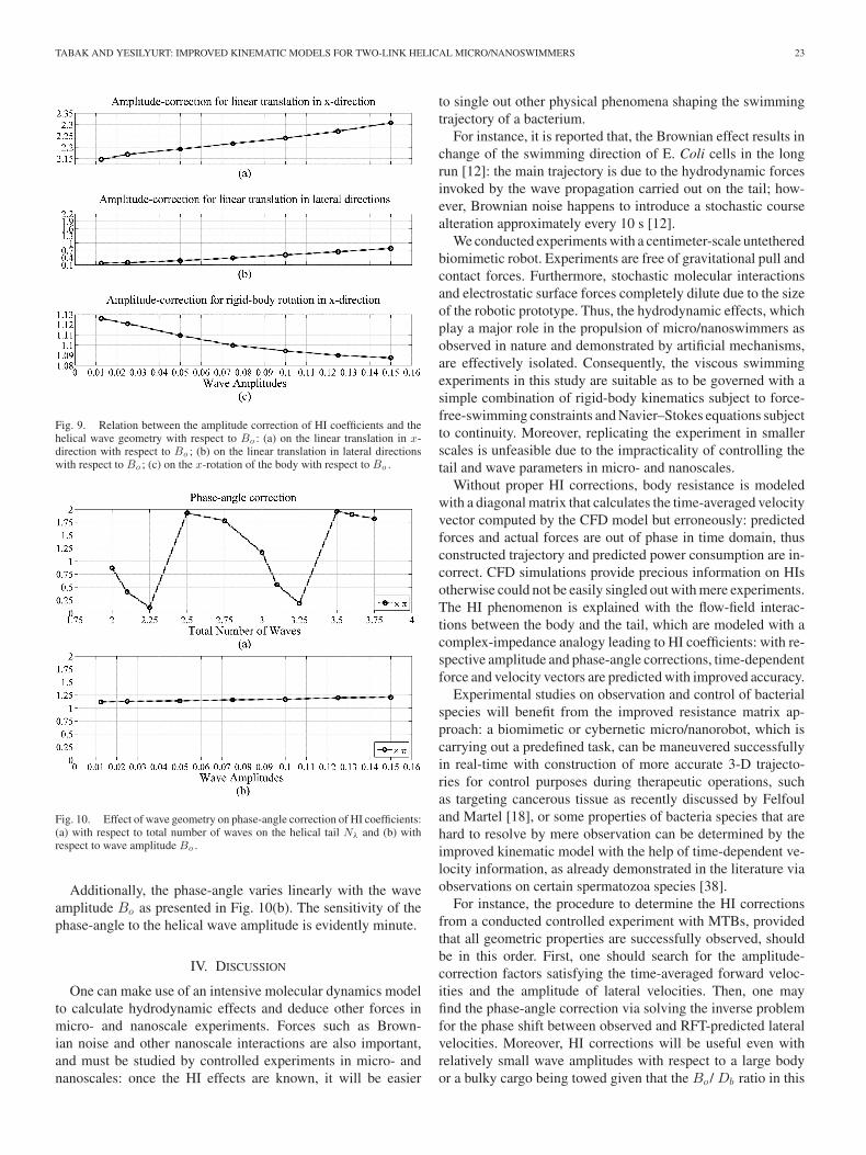
The relationship between ΥT ,x and wave amplitude is linear:the normal stress that is acting on the hemispherical surface onthe right-hand side of the body increases with increasing Bo ,akin to increasing Nλ [see Fig. 9(a)]. The amplitude correctionof lateral HI coefficient in lateral directions ΥT ,{y ,z}, also varieslinearly with wave amplitude; however, the amplification effectis significantly low [see Fig. 9(b)]. Finally, ΥR,x is inverselyproportional to the wave amplitude, and varies slightly converg-ing to 1 as Bo increases [see Fig. 9(c)]. Hence, the body is lessaffected by the tangential component of the flow field inducedby the counter rotation of the tail.
The base-case CFD simulation computes a 1.17π phase-anglefor the helical tail with Nλ = 3 and Bo = 0.1 as given in Table VI.Phase-angle dips to local minima for wavelengths shorter thanhalf-wave on the tail, i.e., including quarter of a wavelengthsuch as Nλ = {0.25, 1.25, 2.25, 3.25,. . .} to be exact [seeFig. 10(a)]. Local minima of phase-angle coincide with the localmaxima of amplitude correction in lateral directions, as depictedby Figs. 8(b) and 10(a). Moreover, the phase-angle reaches tolocal maxima with the presence of half waves, i.e., Nλ = {0.5,1.5, 2.5, 3.5,. . .}.
TABAK AND YESILYURT: IMPROVED KINEMATIC MODELS FOR TWO-LINK HELICAL MICRO/NANOSWIMMERS 23
Fig. 9. Relation between the amplitude correction of HI coefficients and thehelical wave geometry with respect to Bo : (a) on the linear translation in x-direction with respect to Bo ; (b) on the linear translation in lateral directionswith respect to Bo ; (c) on the x-rotation of the body with respect to Bo .
Fig. 10. Effect of wave geometry on phase-angle correction of HI coefficients:(a) with respect to total number of waves on the helical tail Nλ and (b) withrespect to wave amplitude Bo .
Additionally, the phase-angle varies linearly with the waveamplitude Bo as presented in Fig. 10(b). The sensitivity of thephase-angle to the helical wave amplitude is evidently minute.
IV. DISCUSSION
One can make use of an intensive molecular dynamics modelto calculate hydrodynamic effects and deduce other forces inmicro- and nanoscale experiments. Forces such as Brown-ian noise and other nanoscale interactions are also important,and must be studied by controlled experiments in micro- andnanoscales: once the HI effects are known, it will be easier
to single out other physical phenomena shaping the swimmingtrajectory of a bacterium.
For instance, it is reported that, the Brownian effect results inchange of the swimming direction of E. Coli cells in the longrun [12]: the main trajectory is due to the hydrodynamic forcesinvoked by the wave propagation carried out on the tail; how-ever, Brownian noise happens to introduce a stochastic coursealteration approximately every 10 s [12].
We conducted experiments with a centimeter-scale untetheredbiomimetic robot. Experiments are free of gravitational pull andcontact forces. Furthermore, stochastic molecular interactionsand electrostatic surface forces completely dilute due to the sizeof the robotic prototype. Thus, the hydrodynamic effects, whichplay a major role in the propulsion of micro/nanoswimmers asobserved in nature and demonstrated by artificial mechanisms,are effectively isolated. Consequently, the viscous swimmingexperiments in this study are suitable as to be governed with asimple combination of rigid-body kinematics subject to force-free-swimming constraints and Navier–Stokes equations subjectto continuity. Moreover, replicating the experiment in smallerscales is unfeasible due to the impracticality of controlling thetail and wave parameters in micro- and nanoscales.
Without proper HI corrections, body resistance is modeledwith a diagonal matrix that calculates the time-averaged velocityvector computed by the CFD model but erroneously: predictedforces and actual forces are out of phase in time domain, thusconstructed trajectory and predicted power consumption are in-correct. CFD simulations provide precious information on HIsotherwise could not be easily singled out with mere experiments.The HI phenomenon is explained with the flow-field interac-tions between the body and the tail, which are modeled with acomplex-impedance analogy leading to HI coefficients: with re-spective amplitude and phase-angle corrections, time-dependentforce and velocity vectors are predicted with improved accuracy.
Experimental studies on observation and control of bacterialspecies will benefit from the improved resistance matrix ap-proach: a biomimetic or cybernetic micro/nanorobot, which iscarrying out a predefined task, can be maneuvered successfullyin real-time with construction of more accurate 3-D trajecto-ries for control purposes during therapeutic operations, suchas targeting cancerous tissue as recently discussed by Felfouland Martel [18], or some properties of bacteria species that arehard to resolve by mere observation can be determined by theimproved kinematic model with the help of time-dependent ve-locity information, as already demonstrated in the literature viaobservations on certain spermatozoa species [38].
For instance, the procedure to determine the HI correctionsfrom a conducted controlled experiment with MTBs, providedthat all geometric properties are successfully observed, shouldbe in this order. First, one should search for the amplitude-correction factors satisfying the time-averaged forward veloc-ities and the amplitude of lateral velocities. Then, one mayfind the phase-angle correction via solving the inverse problemfor the phase shift between observed and RFT-predicted lateralvelocities. Moreover, HI corrections will be useful even withrelatively small wave amplitudes with respect to a large bodyor a bulky cargo being towed given that the Bo / Db ratio in this
24 IEEE TRANSACTIONS ON ROBOTICS, VOL. 30, NO. 1, FEBRUARY 2014
study varies between 0.01 and 0.15. It is also noted that, for two-link helical swimmers, phase-angle and amplitude correctionsare not a function of one another.
V. CONCLUSION
Biomimetic micro/nanorobots and single-celled organismsare of great importance for future in vivo and in vitro applicationsin biomedicine such as minimal invasive surgery. Hence, im-proved hydrodynamic models based on well-known resistancecoefficients will be extremely useful for accurate trajectory gen-eration and control of natural micro/nanoswimmers. Hence, wefocused on improving an otherwise well-known deterministictool.
We conducted dimensionless time-dependent CFD simula-tions in order to study the flow fields induced by a helical swim-mer in viscous domains. We qualitatively studied the effect ofthe body geometry on the induced flow field: tail rotation am-plifies the hydrodynamic stress increasing the spatial streamlinedensity at the back of the spherical body. After examining theflow fields and swimmer trajectory in detail, we quantified theHI between the swimmer’s body and a rotating helical tail byintroducing two HI coefficients, i.e., amplitude and phase-anglecorrections, based on complex-impedance analysis carried outon the time-dependent hydrodynamic force vector. The modifiedresistance matrix and the improved RFT model are demonstratedto be indispensable in micro/nanorobotic applications with theability to predict time dependent force vectors accurately.
Furthermore, we quantitatively studied the relationship be-tween HI coefficients, and the wave geometry. It is demonstratedthat the phase-angle of the lateral HI has a nonlinear relationshipwith total number of waves and mildly sensitive to the wave am-plitude: the nonlinear sensitivity to wavenumber indicates theneed for further study within a wider design space with higherresolution.
REFERENCES
[1] S. Martel, O. Felfoul, J.-B. Mathieu, A. Chanu, S. Tamaz, M. Mohammadi,M. Mankiewicz, and S. N. Tabatabaei, “MRI-based medical nanoroboticplatform for the control of magnetic nanoparticles and flagellated bacteriafor target interventions in human capillaries,” Int. J. Robot Res., vol. 28,no. 9, pp. 1169–1182, Sep. 2009.
[2] B. J. Nelson, I. K. Kaliakatsos, and J. J. Abbott, “Microrobots for mini-mally invasive medicine,” Annu. Rev. Biomed. Eng., vol. 12, pp. 55–85,Aug. 2010.
[3] T. Honda, K. I. Arat, and K. Ishiyama, “Micro swimming mechanismspropelled by external magnetic fields,” IEEE Trans. Magn., vol. 32, no. 5,pp. 5085–5087, Sep. 1996.
[4] R. Dreyfus, J. Baudry, M. L. Roper, M. Fermigier, H. A. Stone, andJ. Bibette, “Microscopic artificial swimmers,” Nature, vol. 437, pp. 862–865, Oct. 2005.
[5] T. S. Yu, E. Lauga, and A. E. Hosoi, “Experimental investigations of elastictail propulsion at low Reynolds number,” Phys. Fluids, vol. 18, no. 9,pp. 091701-1–091701-4, Sep. 2006.
[6] G. Kosa, M. Shoham, and M. Zaaroor, “Propulsion method for swimmingmicrorobots,” IEEE Trans. Robot., vol. 23, no. 1, pp. 137–150, Feb. 2007.
[7] L. Zhang, J. J. Abbott, L. Dong, B. E. Kratochvil, D. Bell, and B. J. Nelson,“Artificial bacterial flagella: Fabrication and magnetic control,” Appl.Phys. Lett., vol. 94, no. 6, pp. 064107-1–064107-3, Feb. 2009.
[8] B. Chen, S. Jiang, Y. Liu, Y. Yang, and S. Chen, “Research on the kinematicproperties of a sperm-like swimming micro robot,” J. Bionic Eng., vol. 7,pp. S123–S129, Sep. 2010.
[9] L. Arcese, M. Fruchard, and A. Ferreira, “Endovascular magneticallyguided robots: Navigation modeling and optimization,” IEEE Trans.Biomed. Eng., vol. 59, no. 4, pp. 977–987, Apr. 2012.
[10] J. J. Abbott, K. E. Peyer, M. C. Lagomarsino, L. Zhang, L. Dong,I. K. Kaliakatsos, and B. J. Nelson, “How should microrobots swim?,”The Int. J. Robot Res., vol. 28, no. 11–12, pp. 1434–1447, Nov./Dec.2009.
[11] C. Brennen and H. Winet, “Fluid mechanics of propulsion by cilia andflagella,” Annu. Rev. Fluid Mech., vol. 9, pp. 339–398, Jan. 1977.
[12] H. C. Berg, “Navigation on a micron scale,” in Controlled NanoscaleMotion (Lecture Notes in Physics), vol. 711, H. Linke and A. Mansson,Eds. Berlin, Germany: Springer-Verlag, 2007, pp. 1–13.
[13] R. T. Tjeung, M. S. Hughes, L. Y. Yeo, and J. R. Friend, “Surface acousticwave micromotor with arbitrary axis rotational capability,” Appl. Phys.Lett., vol. 99, no. 21, pp. 214101-1–214101-3, Nov. 2011.
[14] H. C. Berg, “The rotary motor of bacterial flagella,” Annu. Rev. Biochem.,vol. 72, pp. 19–54, Jul. 2003.
[15] T. Fukuda, F. Arai, and M. Nakajima, Micro-Nanorobotic ManipulationSystems and Their Applications. New York, NY, USA: Springer-Verlag,2013, pp. 137–139.
[16] X. Xiong, M. E. Lidstrom, and B. A. Parviz, “Microorganisms forMEMS,” J. Microelectromech. S., vol. 16, no. 2, pp. 429–444, Apr. 2007.
[17] S. Martel, “Bacterial microsystems and microrobots,” Biomed. Microde-vices, vol. 14, no. 6, pp. 1033–1045, Dec. 2012.
[18] O. Felfoul and S. Martel. (Jul. 2013). Assessment of navigationcontrol strategy for magnetotactic bacteria in microchannel: Towardtargeting solid tumors. Biomed. Microdevices. [Online]. Available:http://link.springer.com/content/pdf/10.1007/s10544-013-9794-4.pdf
[19] B. Behkam and M. Sitti, “Characterization of bacterial actuation of micro-objects,” presented at the IEEE Int. Conf. Robotics and Automation, Kobe,Japan, May 12–17, 2009.
[20] S. Martel, “Controlled bacterial micro-actuation,” presented at the Int.Conf. Microtechnologies in Medicine and Biology, Okinawa, Japan, May9–12, 2006.
[21] S. Martel, C. C. Tremblay, S. Ngakeng, and G. Langlois, “Control manip-ulation and actuation of micro-objects with magnetotactic bacteria,” Appl.Phys. Lett., vol. 89, no. 23, pp. 233904-1–233904-3, Dec. 2006.
[22] S. Martel and M. Mohammadi, “A robotic micro-assembly process in-spired by the construction of the ancient pyramids and relying on severalthousand flagellated bacteria acting as micro-workers,” presented at theIEEE/RSJ Int. Conf. Intelligent Robots and Systems, St. Louis, MO, USA,Oct. 11–15, 2009.
[23] A. Uenoyama and M. Miyata, “Gliding ghosts of mycoplasma mobile,”Proc. Natl. Acad. Sci. USA, vol. 102, no. 36, pp. 12754–12758, Sep. 2005.
[24] B. Behkam and M. Sitti, “Bacterial flagella-based propulsion and on/offmotion control of microscale objects,” Appl. Phys. Lett., vol. 90, no. 2,pp. 023902-1–023902-3, Jan. 2007.
[25] K. Nogawa, M. Kojima, M. Nakajima, S. Kojima, M. Homma, andT. Fukuda, “Rotational speed control of Na+ -driven flagellar motor bynano/micro dual pipettes,” IEEE Trans. Nanobiosci., vol. 8, no. 4, pp. 341–348, Dec. 2009.
[26] M. A. Sleigh, The Biology of Cilia and Flagella. New York, NY, USA:Macmillan, 1962, pp. 89–94.
[27] G. J. Hancock, “The self-propulsion of microscopic organisms throughliquids,” Proc. Roy. Soc. Lond. A Math., vol. 217, no. 1128, pp. 96–121,Mar. 1953.
[28] J. Gray and G. J. Hancock, “The propulsion of sea-urchin spermatozoa,”J. Exp. Biol., vol. 32, pp. 802–814, Dec. 1955.
[29] J. Lighthill, “Flagellar hydrodynamics: The John von Neumann lecture,”SIAM Rev., vol. 18, no. 2, pp. 161–230, Apr. 1976.
[30] H. C. Berg, Random Walks in Biology. New Expanded, Ed. Princeton,NJ, USA: Princeton Univ. Press, 1993, pp. 56–57, 83–84.
[31] F. Perrin, “Mouvement brownien d’un ellipsoıde (i). dispersiondielectrique pour des molecules ellipsoıdales,” J. Phys. Radium, vol. 5,pp. 497–511, Oct. 1934.
[32] J. B. Keller and S. I. Rubinow, “Swimming of flagellated microorgan-isms,” Biophys. J., vol. 16, no. 2, pp. 151–170, Feb. 1976.
[33] J. G. de la Torre and V. A. Bloomfield, “Hydrodynamic theory of swim-ming of flagellated microorganisms,” Biophys. J., vol. 20, no. 1, pp. 49–67,Oct. 1977.
[34] R. E. Johnson, “An improved slender-body theory for Stokes flow,” J.Fluid Mech., vol. 99, no. 2, pp. 411–431, Jul. 1980.
[35] N. Watari and R. G. Larson, “The hydrodynamics of a run-and-thumblebacterium propelled by polymophic helical flagella,” Biophys. J., vol. 98,no. 1, pp. 12–17, Jan. 2010.
TABAK AND YESILYURT: IMPROVED KINEMATIC MODELS FOR TWO-LINK HELICAL MICRO/NANOSWIMMERS 25
[36] N. Phan-Thien, T. Tran-Cong, and M. Ramia, “A boundary-element anal-ysis of flagellar propulsion,” J. Fluid Mech., vol. 184, pp. 533–549, Nov.1987.
[37] M. Ramia, D. L. Tullock, and N. Phan-Thien, “Role of hydrodynamicinteraction in the locomotion of microorganisms,” Biophys. J., vol. 65,no. 2, pp. 755–778, Aug. 1993.
[38] B. M. Friedrich, I. H. Riedel-Kruse, J. Howard, and F. Julicher, “High-precision tracking of sperm swimming fine structure provides strong testof resistive force theory,” J. Exp. Biol., vol. 213, no. 8, pp. 1226–1234,Apr. 2010.
[39] V. B. Shenoy, D. T. Tambe, A. Prasad, and J. A. Theriot, “A kinematicdescription of the trajectories of listeria monocytogenes propelled by actincomet tails,” Proc. Natl. Acad. Sci. USA, vol. 104, no. 20, pp. 8229–8234,May 2007.
[40] Y. Pan, W. Lin, J. Li, W. Wu, L. Tian, C. Deng, Q. Liu, R. Zhu,M. Winklhofer, and N. Petersen, “Reduced efficiency of magnetotaxisin magnetotactic coccoid bacteria in higher than geomagnetic fields,”Biophys. J., vol. 97, no. 4, pp. 986–991, Aug. 2009.
[41] T. Hasegawa, N. Ogawa, H. Oku, and M. Ishikawa, “A new frameworkfor microrobotic control of motile cells based on high-speed tracking andfocusing,” presented at the IEEE Int. Conf. Robotics and Automation,Pasadena, CA, USA, May 19–23, 2008.
[42] K. Drescher, K. C. Leptos, and R. E. Goldstein, “How to track protistsin three dimensions,” Rev. Sci. Instrum., vol. 80, no. 1, pp. 014301-1–014301-7, Jan. 2009.
[43] E. Gurarie, D. Grunbaum, and M. T. Nishizaki, “Estimating 3D move-ments from 2D observations using a continuous model of helical swim-ming,” Bull. Math. Biol., vol. 73, no. 6, pp. 1358–1377, Jun. 2011.
[44] E. Lauga, W. R. DiLuzio, G. M. Whitesides, and H. A. Stone, “Swimmingin circles: Motion on bacteria near solid boundaries,” Biophys. J., vol. 90,pp. 400–412, Jan. 2006.
[45] A. Ghosh and P. Fischer, “Controlled propulsion of artificial magneticnanostructured propellers,” Nano Lett., vol. 9, no. 6, pp. 2243–2245, May2009.
[46] L. Zhang, J. J. Abbott, L. Dong, K. E. Peyer, B. E. Kratochvil, H. Zhang,C. Bergeles, and B. J. Nelson, “Characterizing the swimming propertiesof artificial bacterial flagella,” Nano. Lett., vol. 9, no. 10, pp. 3663–3667,Sep. 2009.
[47] A. W. Mahoney, J. C. Sarrazin, E. Bamberg, and J. J. Abbott, “Velocitycontrol with gravity compensation for magnetic helical microswimmers,”Adv. Robot., vol. 25, no. 8, pp. 1007–1028, Jan. 2011.
[48] A. F. Tabak, F. Z. Temel, and S. Yesilyurt, “Comparison on experimentaland numerical results for helical swimmers inside channels,” presented atthe IEEE/RSJ Int. Conf. Intelligent Robots and Systems, San Francisco,CA, USA, Sep. 25–30, 2011.
[49] A. F. Tabak and S. Yesilyurt, “In-channel experiments on vertical swim-ming with bacteria-like robots,” presented at the IEEE/RSJ Int. Conf.Intelligent Robots and Systems, Tokyo, Japan, Nov. 3–7, 2013.
[50] S. Chattopadhyay and X.-L. Wu, “The effect of long-range hydrodynamicinteraction on the swimming of a single bacterium,” Biophys. J., vol. 96,no. 5, pp. 2023–2028, Mar. 2009.
[51] J. J. L. Higdon, “The hydrodynamics of flagellar propulsion: Helicalwaves,” J. Fluid Mech., vol. 94, no. 2, pp. 331–351, Sep. 1979.
[52] G. I. Taylor, “Analysis of the swimming of microscopic organisms,” Proc.Roy. Soc. Lond. A Math., vol. 209, no. 1099, pp. 447–461, Nov. 1951.
[53] A. J. Hanson and H. Ma, “Quaternion frame approach to streamline visu-alization,” IEEE Trans. Vis. Comput. Graphics, vol. 1, no. 2, pp. 164–174,Jun. 1995.
[54] R. G. M. van der Sman, “Effects of confinement on hydrodynamic interac-tion between a suspended sphere and stationary objects,” Comput. Fluids,vol. 58, pp. 63–69, Apr. 2012.
[55] F. Duarte, R. Gormaz, and S. Natesan, S., “Arbitrary Lagrangian-Eulerianmethod for Navier-Stokes equations with moving boundaries,” Comput.Method. Appl. M. Eng., vol. 193, no. 45, pp. 4819–4836, Nov. 2004.
[56] Comsol Multiphysics Modeling Guide, COMSOL AB, Stockholm, Swe-den, 2012.
[57] Y. Hyon, Marcos, T. R. Powers, R. Stocker, and H. C. Fu, “The wigglingtrajectories of bacteria,” J. Fluid Mech., vol. 705, pp. 58–76, Aug. 2012.
[58] L. F. Shampine and M. W. Reichelt, “The Matlab ODE suite,” SIAM J.Sci. Comput., vol. 18, no. 1, pp. 1–22, Jan. 1997.
[59] O. Schenk and K. Gartner, “Solving unsymmetric sparse systems of lin-ear equations with pardiso,” Future Gener. Comput. Syt., vol. 20, no. 3,pp. 475–487, Apr. 2004.
[60] F.-H. Qin, W.-X. Huang, and H. J. Sung, “Simulation of small swim-mer motions driven by tail/flagellum beating,” Comput. Fluids, vol. 55,pp. 109–117, Feb. 2011.
[61] R. Maniyeri, Y. K. Suh, S. Kang, and M. J. Kim, “Numerical study on thepropulsion of a bacterial flagellum in a viscous fluid using an immersedboundary method,” Comput. Fluids, vol. 62, pp. 13–24, Jun. 2012.
[62] A. F. Tabak and S. Yesilyurt, “Simulation-based analysis of flow due totraveling-plane-wave deformations on elastic thin-film actuators in mi-cropumps,” Microfluid. Nanofluid., vol. 4, no. 6, pp. 489–500, Jun. 2008.
[63] O. Raz and J. E. Avron, “Swimming, pumping and gliding at low Reynoldsnumbers,” New J. Phys., vol. 9, pp. 437–445, Dec. 2007.
[64] J.-M. Bourot, “On the numerical computation of the optimum profile inStokes flow,” J. Fluid Mech., vol. 65, no. 3, pp. 513–515, Sep. 1974.
[65] H. Shum, E. A. Gaffney, and D. J. Smith, “Modeling bacterial behaviorclose to a no-slip plane boundary: The influence of bacterial geometry,”Proc. Roy. Soc. Lond. A Math., vol. 466, no. 2118, pp. 1725–1748, Jan.2010.
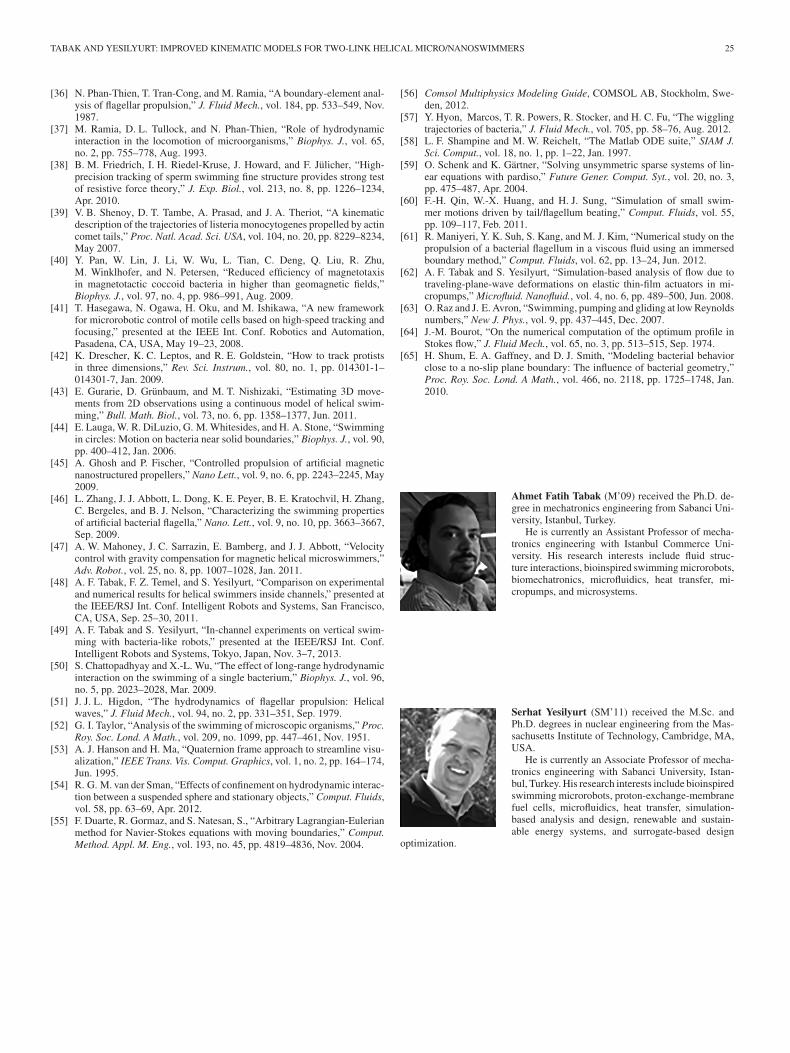
Ahmet Fatih Tabak (M’09) received the Ph.D. de-gree in mechatronics engineering from Sabanci Uni-versity, Istanbul, Turkey.
He is currently an Assistant Professor of mecha-tronics engineering with Istanbul Commerce Uni-versity. His research interests include fluid struc-ture interactions, bioinspired swimming microrobots,biomechatronics, microfluidics, heat transfer, mi-cropumps, and microsystems.
Serhat Yesilyurt (SM’11) received the M.Sc. andPh.D. degrees in nuclear engineering from the Mas-sachusetts Institute of Technology, Cambridge, MA,USA.
He is currently an Associate Professor of mecha-tronics engineering with Sabanci University, Istan-bul, Turkey. His research interests include bioinspiredswimming microrobots, proton-exchange-membranefuel cells, microfluidics, heat transfer, simulation-based analysis and design, renewable and sustain-able energy systems, and surrogate-based design
optimization.