Embed Size (px)
Citation preview

Improved Islanding Detection Scheme for
Multiple Inverter Based DG Systems
Veenaj K V, P.G. Scholar , & Manju Padma,
Assistant Professor ,
Department of Electrical & Electronics Engineering ,
Thejus Engineering College, Thrissur, Kerala
Abstract— Islanding operation is most important function of
DG connected grid system. So we already develop the islanding
techniques, which is based on lot of parameters, in this paper
discussed an improved method compared with old techniques.
Here a harmonic current disturbance is imposed to grid at one of
the harmonic frequency, which is associated with grid voltage.
Disturbance imposed by changing the parallel impedance of
inverter. Our islanding detection signal is the output current of
grid connected inverter at a specific harmonic frequency. In this
method does not affect the overall power quality of system,
because our harmonic resonance is imposed over a short time
interval. We used multiple DG systems, there is no interference
between the parallel DG’s is observed. The performance of
proposed method analised using time-domain simulation carried
out in Matlab software.
I. INTRODUCTION
For improving the power distribution reliability and capability
, we considering distributed Energy Resources (DER)
including distributed Generation (DG) and Distributed
Storage (DS) are, as renewable energy resources. The most
important features of DG system is their capability for
working in both islanded and grid-connected mode. An
important technical issue with DG systems is unintentional
islanding operation, so special consideration should be made
regarding the safe operation of DG’s during connecting and
disconnecting to or from the grid [2]. They have lot of
methods to overcomes this issues presently, but some have
less efficient, more maintenance issues, security problems and
also cost problems.
The island can occur when a part of grid is electrically
isolated from the power system but the part with island is
energized by distributed generators. This condition though
helps with continuity of supply to local loads, we can operate
the loads without any delays which leads to reducing the lost
occurred in our field. The above condition can create some
problems like power quality problems (voltage and frequency
instability), equipment damages and safety hazards[1]. And it
constitutes a great risk for maintenance of power system parts
the importance of human and equipment protection,
unintentional islanding for DG operation is not tolerated. For
these reasons the detection of unintentional islanding is an
important concern for DG system in micro grid, operation is
required as rapidly as possible to allow the timely
disconnection of the DG units [1,2] Islanding is one of the
most technical concerns associated with the proliferation of
distributed generation connected to utility networks.
They have large number of classification on islanding
depending on many factors. Mainly the classification into
Remote and local techniques. Remote techniques such as
Supervisory Control and Data Acquisition (SCADA), Trip
(disconnect) Signal and Power Line Carrier Communication
(PLCC) systems. They offer high performance and
applicability on multi-source topologies. The main drawbacks
of those centralized methods are expensive to implant [5].
Local techniques again classified into passive and active
methods which are implemented on the DG side. Passive
methods have a large Non Detection Zone (NDZ), this is the
main disadvantage of this method, hence are not useful for
high DG penetration. A solution for the NDZ reduction is the
utilization of active anti-islanding methods. This method is
based on injecting a disturbance to grid and then measuring
the grid response [1]. Active methods deals with two cases,
in first case each DG imposes a small disturbance on grid
variable like voltage or frequency which used to detect the
operational mode. Second group is based on harmonic
injection to grid then to measure grid impedance.
A single-line diagram of the basic system configuration is
shown in Fig.1; we assume that the DG system consists of a
dc source, an inverter, a filter, a transformer, and a controller.
The inverting DG structure connected in parallel to the grid
and feeding RLC load at the same time, we can assume that
there is large numbers of DG structures are connected parallel
for improving power delivering to the grid or load system.
The key role in operation play with the help of controller,
which helps managing, and protecting the DG system. In
normal model, the controller uses unintentional islanding
technique which means that once the islanding occurs the DG
disconnects itself from the rest of the system to prevent itself
and the load. With the help of circuit breaker the DG system
will be disconnect from grid system (islanding). After
interrupting of CB there will be variations in system voltage,
frequency, active and reactive power and THD. In normal
cases the voltage and frequency changes can be detected by
over/under voltage and over/under frequency relays[3].
International Journal of Engineering Research & Technology (IJERT)
ISSN: 2278-0181http://www.ijert.org
IJERTV6IS040199(This work is licensed under a Creative Commons Attribution 4.0 International License.)
Published by :
www.ijert.org
Vol. 6 Issue 04, April-2017
155

Fig.1 A single-line diagram of the basic system configuration
In normal condition there is no errors occurred in the
system, the power produced from DG is delivered to the grid.
In normal condition the DG generated power is very less
compared with the large load, so the remaining power is
consumed the load from grid. Difficulties appear when a load
demand and DG generation are close. Now a day’s the
development of DG recourses improved and also their
efficiency also improved. Then frequency or voltage changes
can be insufficient to enable detection by inverter. This leads
to develop some islanding techniques which can detect these
cases when the powers of DG and load are closely matched
[3].
In this paper deals with above problem (the generation
power from DG and consumption power of load closely
matched). Our islanding detection method is a new one which
is cope with the active method. One of the attractive active
methods is frequency shift method, We introduce a small
perturbation in form of phase shift. When the DG is grid
connected, the frequency will be stabilized. When the system
is islanded, the perturbation will result in significant change in
frequency. The drawback of this method is that the islanding
can go undetected if the slope of the phase of the load is
higher than that of the SMS(Slip-Mode Frequency Shift) line,
as there can be stable operating points within the unstable
zone[5].
II. DESCRIPTION OF THE PROPOSED METHOD
The concept of the proposed islanding detection method
shown in fig.2, a single phase grid connected inverter with an
LCL filter. Our present strategy can be used for single phase
also three-phase grid-connected inverters interfacing any type
of energy resources like renewable or storage system to the
grid or load. The idea of the method can also be customized
for any type of inverter output filter by considering its control
loop. In the fig.2 shows a single phase inverter with LCL
filter and RLC load, the grid is modeled as a voltage source
which is in series with its Thevenin impedance. The real and
reactive power of the RLC load is considered to be equal to
the output real and reactive power of the inverter; this is the
main principle behind the islanding detection [10,11]. The
RLC load is modeled with the resonance frequency of 50Hz
and the quality factor of 2.5[9].
Fig. 2 Grid connected inverter with local RLC load
In our proposed system the dc source considered as
renewable energy source system, we assume they delivered a
constant output power to inverter section. Islanding of the grid
connected generators (photovoltaic system) can occur when
the part of utility system having such generators is
disconnected from the main grid and independent generators
keep to energize the isolated part. The system consists DG
sourse, an inverter, a local load (parallel RLC), a switch
(breaker, fuse) and the grid. The distribution generation is
considered to be in unity power factor operation. Consider the
worst case for islanding detection when the active power of
load matches to output power of distribution generation. For
simulations the worst case is used as test conditions according
to UL1741, IEEE 929 and IEEE 1547 [12,13]:
1. The power generated by DG should match the RLC load
power, ∆P = 0 and ∆Q = 0.
2. Resonant frequency of the RLC load is the same as grid
line frequency ( f = 50Hz).
3. The quality factor Qf of RLC load is set to be 2.5. The
quality factor is defined as that the reactive power stored in L
or C is Qf times the active power consumed in R.
Under these conditions, when the grid is disconnected, the
distributed generation and RLC load will resonate at nominal
voltage and frequency to form an island, unless there is a
mechanism to drive voltage at PCC or frequency out of their
nominal range [6].
The overall structure of the control system of grid
connected inverter is shown fig . we can see that plant model
consists single phase inverter with LCL filter and grid. The
control system consists of an inner current control loop and an
outer dc-bus voltage control loop. The dc-bus voltage control
loop is composed of a PI controller which regulates the dc
link voltage by providing the reference signal for the current
control loop (Iref); however, as shown in Fig. 2, Iref can be
externally adjusted for dispatch able resources. The current
control loop which is composed of a proportional resonant
(PR) controller can effectively track the reference signal
which is provided by the current reference generator block in
Fig. 2. The frequency and the phase of the reference current
(Iref) are determined by utilizing the Phase Locked Loop
(PLL) block[1]. The current controller with its harmonic
compensators is expressed as:
Gc(𝑠) = 𝐾𝑝𝑐 +𝐾𝑖𝑐𝑠
𝑠2 + 2𝜔𝑐𝑠 + 𝜔𝑓2
+ ∑ (ℎ=3,5,7,9
Kihs
s2 + 2hωcs + (hωf)2
)
International Journal of Engineering Research & Technology (IJERT)
ISSN: 2278-0181http://www.ijert.org
IJERTV6IS040199(This work is licensed under a Creative Commons Attribution 4.0 International License.)
Published by :
www.ijert.org
Vol. 6 Issue 04, April-2017
156
As the interface between the distributed power generation
system and power grid, grid-connected inverter plays an
important role in injecting high-quality power into the grid. In
our system an LCL filter is placed between the inverter and
the grid to attenuate the switching frequency harmonics
produced by the grid-connected inverter. Compared with
other filter, LCL filter has better attenuation of the switching
frequency harmonics, which usually yields lower volume and
costs, so we adopt LCL filter. The resonance of the LCL filter
requires proper damping methods to avoid the possible
instability of the system [7]. So we provide an active damping
method which is based on the capacitor current feedback is
utilized to prevent resonance conditions. The active damping
gain helps to provide a suitable damping ratio in the
resonance frequency of the LCL filter. Figure shows the
proposed islanding detection block is added to the active
damping loop which is presented as “intentional resonance
creation” block[1].
The output current of current controlled inverter IDG, can
be written as,
IDG(𝑠) = 𝐻(𝑠)𝐼𝑟𝑒𝑓(𝑠) −𝑉𝑝𝑐𝑐(𝑠)
𝑧𝑝(𝑠)
The reference current and point of common coupling (PCC),
are considered for determining output current of inverter. H(s)
referred to as closed loop transfer function . We know that
there is harmonics occurs in grid system, so these harmonics
of Vpcc cause current harmonic according to the magnitude of
Zp(s) at any harmonic frequency, the equivalent parallel
impedance of inverter takes a very low value at a given
harmonic frequency , the THD (total harmonic distortion) of
the output current increases.
Fg.3 (a) closed loop model of grid connected inverter, (b) equivalent circuit
of system
The main principle behind of our proposed islanding
detection method is, there is an active damping loop which is
created by capacitor current feedback gain can affect the
transfer function of the grid connected inverter. The feedback
implementation can control output harmonic currents[1].
Fig.4 proposed system configuration
In our proposed method, we intentionally create a
harmonic resonance on the output current
of inverter at a
specified frequency namely fres which is associated with one
of the odd harmonic if the
grid voltage. Our harmonic
frequency is a selectable value, the resonance creation can be
done by an appropriate feedback implementation in control
system of each grid connected inverter.
In normal condition of grid , they have some harmonics are
present. We considered these harmonics for our concern, we
consider the case of grid disconnection, the source of
harmonics of grid voltage is not present anymore. So, output
current of the inverter at does not change. In grid-connected
mode during which the grid voltage is contains odd
harmonics. The root mean square (RMS) of the output current
of the inverter is changed in both mode of operation,
so that
these is taken as the islanding detection signal.
For islanding method purpose the harmonic resonance is
imposed over a short time interval while the inverter current
at fres is measured at the same time interval. The harmonic
resonance is imposed over a short time interval, so THD of
the inverter current is not significantly affected. Our method
is different from previous methods which are based on the
measurement of the voltage THD. Voltage THD measurement
method depends on parameters like grid impedance and
harmonics of the grid voltage, while due to the adaptive
tuning ability of feedback parameters (used in our system),
the performance of the proposed method is not markedly
affected by these issues (grid impedance and harmonics of the
grid voltage). We can be concluded that, though,
harmonic
content of DGs’ currents affected due to the grid parameters;
the adaptive tuning of feedback parameters can compensate
this effect.
Our harmonic resonance current is created by
changing the equivalent parallel impedance of the inverter.
The parallel impedance adjusted by use of a feedback from
the capacitor current of the inverter’s output filter at fres . The
important feature is that, resonance frequency should be far
from both the fundamental frequency of the system and the
resonance frequency of the admittance seen from the grid. For
this the inverse of a second-order notch filter which is tuned
at fres is used.
Fig.5 equivalent parallel admittance of inverter with and without notch filter-based feedback
The block diagram consists of plant model and all control
loops of system. We derive all algebraic equation in s domain
by all linear differential equation of plants and controllers.
Arbitrary transfer function can be formed with the help of
International Journal of Engineering Research & Technology (IJERT)
ISSN: 2278-0181http://www.ijert.org
IJERTV6IS040199(This work is licensed under a Creative Commons Attribution 4.0 International License.)
Published by :
www.ijert.org
Vol. 6 Issue 04, April-2017
157

mason’s gain formula [1,8]. Bode diagram of the equivalent
parallel admittance of the inverter with and without notch
filter (resonance creation loop) is shown in fig. we can seen
that notch filter leads to a considerable decrease in the
magnitude of the parallel equivalent impedance at fres. The
decrease of parallel impedance results in remarkable increase
in the harmonic component of output current of inverter, this
is our islanding detection signal. We already say that
harmonic resonance is imposed over a short time interval for
fulfill the power quality. For this, the feedback coefficient is
periodically changed. In an complete cycle there are two
regions, one is islanded other is non-islanded. The islanding
condition is checked by imposing the harmonic resonance on
the inverter current .if the period of feedback coefficient
deceases, get fast islanding detection. This damage the power
quality of system, for obtain better power quality during
harmonic resonance imposing , the quality factor of notch
filter is tuned to preserve an acceptable THD of current.
In our basic system only consider the RMS current of
inverter at a specific harmonic frequency (NFc). When the
grid voltage harmonic current order might be equal to non
linear load, in these case islanding detection procedure
malfunctioning. To overcome these problem, we measuring
the THD of inverter terminal voltage. If there is any
frequency variation in the system, so we adopt a frequency
checking unit also. The overall islanding detection procedure
is shown below flowchart.
Fig 6.Flowchart of modified proposed islanding detection method
From the flowchart, when there is no NFC is detected, the
grid connected inverter is in the islanding condition. When
NFC is detected, the follows two situations;
1. If the system have no local nonlinear load, THDV
will be lower than pre-defined threshold (inverter is
still grid connected mode)
2. If the system consists nonlinear load, the load current
have same harmonic current component. In this case,
THDv is smaller than pre-defined threshold (non-
islanding reported).
III. PERFORMANCE OF THE PROPOSED METHOD
FOR MULTIPLE DG SYSTEMS
Fig.7 shows the equivalent circuit of the system with
n-parallel inverters. This inverters output is commonly
connected in point of common coupling. At this point
our load is located and also the grid section is connected.
There is a circuit breaker is placed among the point of
common coupling and the grid section. Which determine
the system is islanded or not. We believe that the total
real and reactive power of RLC load and parallel inverter
are same. And also the parallel impedance of the grid
connected inverter is capacitive at frequencies lower than
the resonance frequency of the filter, so that a resonance
among these inverters and the inductive impedance of
the grid (Zgrid) is likely at a certain frequency that
increases the injected current to the grid at this frequency
[1]. The interaction between the inverter and the main
grid can be explained by a transfer function given [22];
𝐻𝑠𝑒𝑟𝑖𝑒𝑠−𝑅𝑒𝑠𝑜𝑛𝑎𝑛𝑐𝑒(𝑠) = −𝐼𝐷𝐺𝑖
𝑉𝑡ℎ
|𝐼𝑟𝑒𝑓𝑖=0 , 𝑖 = 1,2, … . 𝑁
Fig.7 equivalent circuit of the system with n-parallel inverters.
IV. SIMULATION RESULTS
In this section we validate the effectiveness of our proposed
islanding detection method, a multiple inverter based DG
system with three DGs has been simulated in simulink
software. The dc-link voltage of each inverter can be
considered to be constant, in both inverters dc-link value
should be same. This is help to simulation scenarios. We can
replace this dc-link value to a renewable energy resources like
solar energy, wind, tidal, etc. for this replacement we also
consider it’s control strategies. The power ratings of all
inverter should be equal in this case. The parameters of our
proposed method should be given in below tables. The THD
value of grid voltage is 5% the amplitude of inverter injected
to grid is approximately 10A.
International Journal of Engineering Research & Technology (IJERT)
ISSN: 2278-0181http://www.ijert.org
IJERTV6IS040199(This work is licensed under a Creative Commons Attribution 4.0 International License.)
Published by :
www.ijert.org
Vol. 6 Issue 04, April-2017
158
Parameters Symbols Values
Inverter side inductor L1,r1 10mH,1Ω
Filter capacitor Cf, rc 50μF,50mΩ
Line side inductor L2,r2 2mH,1Ω
Grid impedance Lgrid, Rgrid .02mH,.05Ω
Grid voltage Vgrid 230V
DC link voltage Vdc 415V
Parallel RLC load R,L,C 10Ω ,20H,1 μF
Table:1. Parameters of the circuit of the inverter
Parameters Symbols Values
PR current controller Kpc 20
Kic 4000
ωc 3rad/s
Active damping gain KAD 2
Notch filter coefficients KNF 6
a 12000
b 33.3
Table:2. Filter specification for islanding detection
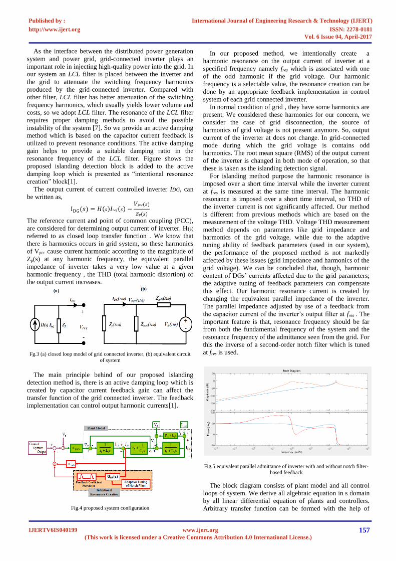
The performance of the proposed system for the islanding
detection technique is validated by MATLAB Simulink
software. Figure 8 shows the simulated diagram of the
system.
Fig 8. Simulated diagram
Simulation section A and B are done for non-linear loads
with considering normal and grid disturbance condition. In
both cases DG provide a constant supply. In grid disturbing
case consists RMS current different based and also THDv
considering cases are discussing. In all condition our RLC
load condition satisfying some standard test (consumption and
generation balance of real and reactive power). Resonant
frequency of RLC load is 50Hz, and the quality factor of 2.5.
Our islanding detection do with the help of a inverse
second order notch filter. This filter is designed by
multiplying inverse transfer function of two notch filter,
which is expressed as:
Goutput−INF(𝑠)
= 𝐾𝑜𝑢𝑡𝑝𝑢𝑡−𝐼𝑁𝐹(s2 + a1s + w2
s2 + b1 + w2)(
s2 + a2s + w2
s2 + b2s + w2)
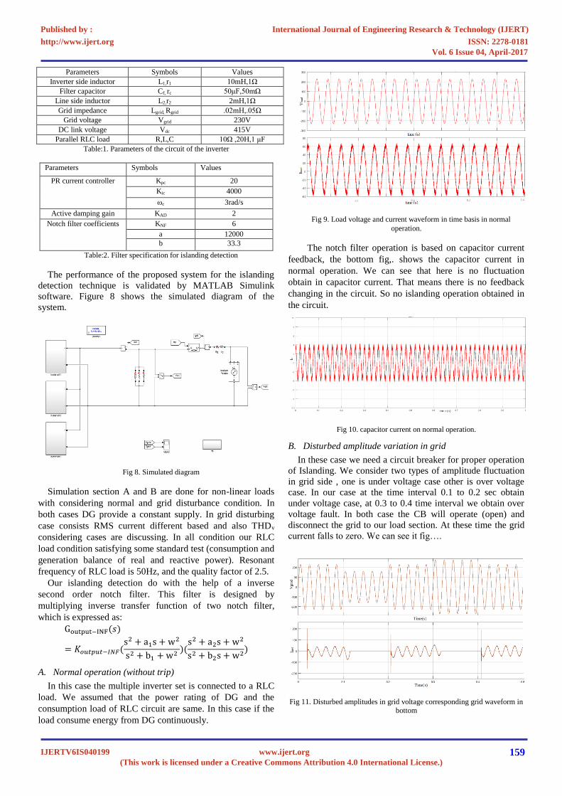
A. Normal operation (without trip)
In this case the multiple inverter set is connected to a RLC
load. We assumed that the power rating of DG and the
consumption load of RLC circuit are same. In this case if the
load consume energy from DG continuously.
Fig 9. Load voltage and current waveform in time basis in normal
operation.
The notch filter operation is based on capacitor current
feedback, the bottom fig,. shows the capacitor current in
normal operation. We can see that here is no fluctuation
obtain in capacitor current. That means there is no feedback
changing in the circuit. So no islanding operation obtained in
the circuit.
Fig 10. capacitor current on normal operation.
B. Disturbed amplitude variation in grid
In these case we need a circuit breaker for proper operation
of Islanding. We consider two types of amplitude fluctuation
in grid side , one is under voltage case other is over voltage
case. In our case at the time interval 0.1 to 0.2 sec obtain
under voltage case, at 0.3 to 0.4 time interval we obtain over
voltage fault. In both case the CB will operate (open) and
disconnect the grid to our load section. At these time the grid
current falls to zero. We can see it fig….
Fig 11. Disturbed amplitudes in grid voltage corresponding grid waveform in
bottom
International Journal of Engineering Research & Technology (IJERT)
ISSN: 2278-0181http://www.ijert.org
IJERTV6IS040199(This work is licensed under a Creative Commons Attribution 4.0 International License.)
Published by :
www.ijert.org
Vol. 6 Issue 04, April-2017
159

At the above condition, the DG will delivered power to
load section for proper operation. These conversion operation
obtain within a short time intervals. We can see the load
current and voltage waveform on both situation. We assumed
that the power delivered from DG and power consumption of
load should be equal. The power values in both islanded and
non-islanded condition are same. The region of islanded (time
interval 0.1-0.2sec and 0.3-0.4sec) section the current value is
obtain from DG, that is the maximum power rating of the DG.
In Fig.13 shows the capacitor current variations in operation.
There is a change of capacitor current in the time of islanding
condition. In our system islanding is based on the capacitor
current feedback, if the grid variation occurred in the system
the capacitor current waveform also change. Based on these
the islanding occurred.
Fig 12. Voltage and current waveform across load in the time of
corresponding amplitude variation
Fig 13. capacitor current waveform during faulty condition
C. THD variation
If the order of the harmonic currents associated with the
nonlinear load be equal to grid voltage which result
malfunctioning of our islanding detection. For prevent these
case we adopt measurement of THD of inverter terminal
voltage. We set a harmonic order of range 8%, if the THD
value greater than our range, then grid connection should
reconnect. This condition is set in bottom figure. The time
interval of 0.1 to 0.3sec the grid voltage occurs large
harmonics. At this time the circuit breaker will open, grid
isolated from load section, the current value on grid down to
zero range.
Fig 14. grid voltage and current on both operation
Fig.15 shows corresponding load voltage and load current.
At the time of islanding the power delivered to the load is
done with DG system. We assumed that the power generation
from DG system and the power consumption of load is same
(Islanding std.).the load continuously operate without any
power deviation. This is the main advantage of our proposed
system. The switching time from normal operation (grid tied)
to islanded taking minute seconds, so there is no power
fluctuation in the load circuit.
Fig 15. voltage and current waveform across load during both operation
The islanding operation is based on capacitor current
feedback. So the variation of capacitor current is properly
detected and corresponding signal is produced with the help
of notch filter. Bottom fig shows the variation of capacitor
current in both mode of operation.
Fig 16. capacitor current waveform on both operation
International Journal of Engineering Research & Technology (IJERT)
ISSN: 2278-0181http://www.ijert.org
IJERTV6IS040199(This work is licensed under a Creative Commons Attribution 4.0 International License.)
Published by :
www.ijert.org
Vol. 6 Issue 04, April-2017
160

V. CONCLUSION
In prior islanding detection method is based on voltage and
frequency measurement units. In case of any generation and
consumption imbalance in the islanded system, the voltage
and frequency protection unit will detect the islanding
condition. For this we need lot of protection devices in each
multiple inverter systems, the advantage of the proposed
method is more pronounced for the situation where there is a
power generation and consumption balance in the islanded
mode. In our system loads are not damaged since the voltage
and frequency of the islanded system will remain in a required
range.
Our proposed islanding detection method suitable for using
in both single and multiple DG systems have been proposed.
The islanding detection system can creating a controlled
harmonic resonance at the output current of the inverter at a
specific harmonic frequency. This resonance current is
periodically imposed to the grid by changing the equivalent
parallel impedance of the inverters. The output current of the
grid-connected inverters at this specific harmonic frequency is
used as our islanding detection signal. The the overall power
quality is not significantly affected because of harmonic
resonance is imposed over a short time interval. In our
proposed method there is no interference among the parallel
DGs was observed which makes it well suited for the
application in systems involving a large number of parallel
inverter-based DGs.
The proposed islanding detection scheme is characterized
by some features for efficient choice for multiple-DG
systems:
There is no interference among parallel DGs is
observed and the islanding detection system shows a
good performance in multiple-DG systems
DGs located within any place of the proposed
islanding detection system can properly work in the
presence of other DGs equipped with any type of
islanding detection scheme.
REFERENCES
[1] Mohsen Hamzeh, Nasim Rashidirad, Keyhan Sheshyekani, Ebrahim
Afjei, “A new islanding detection scheme for multiple inverter based DG systems”, IEEE Trans. On Energy conversion, 2016.
[2] Alben CardenaS, Kodjo Agbossou, Mamadou Lamine DOUMBIA,
“Islanding Detection Method for Multi-Inverter Distributed Generation”, J. Electromagnetic Analysis & Applications, 2009, 3: 170-
180, August 23rd, 2009.
[3] Maher, G. M. Abdolrasol and Saad Mekhilef, “Three phase grid connected anti-islanding controller based on distributed generation
Interconnection“, IEEE international conference on power and energy,
2010. [4] Fernando Briz, David Diaz-Reigosa, Cristian Blanco, Juan M. Guerrero,
“Coordinated Operation of Parallel-Connected Inverters for Active
Islanding Detection Using High Frequency Signal Injection”, IEEE Transactions on Industry Applications, 2013.
[5] L. A. C. Lopes, Y. Zhang, “Islanding Detection Assessment of Multi-
Inverter Systems with Active Frequency Drifting Methods”, IEEE Trans. Power Delivery, vol. 23, no. 1, pp. 480-486, Jan. 2008.
[6] Tomas Skocil, Oriol Gomis-Bellmunt, Daniel Montesano’s-Miracle,
“Passive and Active Methods of Islanding for PV systems”, Departament of Enginyeria Electrica, 2001.
[7] Chenlei Bao, Xinbo Ruan, Xuehua Wang, Weiwei Li, Donghua Pan,
And Kailei Weng “Step-By-Step Controller Design For Lcl-Type Grid-Connected Inverter With Capacitor–Current-Feedback Active-
Damping”, IEEE Transactions On Power Electronics, Vol. 29, No. 3,
March 2014 [8] F. Briz, D. Diaz-Reigosa, C. Blanco, J. Guerrero, “Coordinated
operation of paralleled-connected inverters for active islanding
detection using high frequency signal injection”, IEEE Trans. Ind. Appl., vol. 50, no. 5, pp. 3476-3484, Sep.-Oct. 2014.
[9] L. A. C. Lopes, Y. Zhang, “Islanding Detection Assessment of Multi-
Inverter Systems with Active Frequency Drifting Methods”, IEEE Trans. Power Delivery, vol. 23, no. 1, pp. 480-486, Jan. 2008.
[10] Test procedure of islanding prevention measures for utility-
interconnected photovoltaic inverters, IEC international standard 62116, draft version, Aug. 2006.
[11] Inverters, Converters, and controllers for use in Independent Power
Systems, UL standard 1741, 2001. [12] IEC-International Electrotechnical Commission, Photovoltaic (PV)
systems - characteristics of the utility interface (second edition),
International standard (CEI IEC 61727), pp. 1–24, 2004. www.iec.ch
[13] IEEE Recommended Practice and Requirements for Harmonic Control
in Electric Power Systems," in IEEE Std 519-2014 (Revision of IEEE
Std 519-1992), vol., no., pp.1-29, Jun. 2014.
International Journal of Engineering Research & Technology (IJERT)
ISSN: 2278-0181http://www.ijert.org
IJERTV6IS040199(This work is licensed under a Creative Commons Attribution 4.0 International License.)
Published by :
www.ijert.org
Vol. 6 Issue 04, April-2017
161