Embed Size (px)
Citation preview
Information and Communication Technology
64 July 2017 – EngineerIT
Technical
Improved FTTH installations by reducing fibre sizeby Ian Davis, Corning Optical Communications
One of the most interesting innovations in optical fibre design in recent years has been to reduce the outer coating diameter from the established value of ~250 µm down to ~200 µm. The resulting drop in the fibre cross-sectional area of ~30% can be exploited by optical cable manufacturers to develop compact micro cables with much high fibre density than previously considered possible.
This downsizing enables more efficient use of the access infrastructure and has been made possible by combining the advances made in both the glass and coating components of optical fibre.
Space restrictions demand more attention
to component size
Many network operators planning the roll-out of advanced FTTH services have wrestled with infrastructure issues to ensure that cost-effective installation can be achieved. Utilising the available space efficiently is of uppermost importance. This means making the best use of existing ducts that are already crowded with cables and installing new conduits that support dense fibre deployment to provide the data carrying capacity needed for an expanding subscriber base. Microtrenching technologies, alongside microducts and small diameter micro cables are some of the technologies that can enable delivery of these efficiencies.
In new deployments, microtrenching claims to reduce civil costs by 80% [1]. Instead of digging a traditional trench, a narrow slit is sawn into the surface of the road and populated with microducts of narrow cross-
section. Microducts sub-divide the internal duct space into smaller compartments into which micro cables may be installed. With several ducts available, these may be shared between collaborating operators (also sharing the installation costs) or spare ducts may be leased to competitors. Alternatively, empty ducts may be held until a higher fibre presence is necessary to support expansion of the subscriber base, a “fill-as-you-grow” approach to network upgrade. Of course, smaller microducts require smaller cables to be installed within, with sufficient duct-space available inside to allow fast blowing of the cables over long distances. This is where the new breed of micro cables comes into play. The cable industry has managed to deliver some decent reductions in cable size using standard G.652 fibre of ~250 µm while still meeting industry-required cable performance in developing the first wave of micro cables for telecoms operators. However, a new generation of single-mode optical fibres with a smaller coating diameter has recently been introduced, making it possible to reduce micro cable size even further.
200 µm diameter optical fibre
ITU-T Recommendations G.652 and G.657 describe the geometrical, mechanical and transmission attributes of standard single-
mode and bend-resistant optical fibres respectively. Although optical fibres have evolved greatly since the first commercially viable product was introduced by Corning in the early 1980s, their geometrical dimensions have always remained the same; a 9 µm core and 125 µm cladding traps the light using the principle of internal reflection while a 250 µm diameter coating protects the glass from mechanical damage. The coating also protects the light-carrying capability of the glass by shielding it from external stresses that otherwise could cause small deviations in the axis of the core leading to loss of optical power through the mechanism known as microbending.
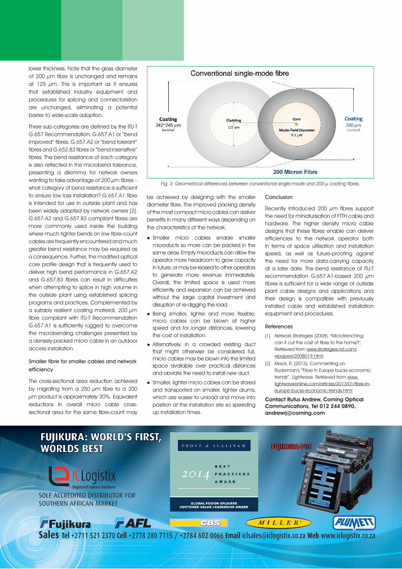
To enable tighter packing of fibre in the cable, the coating diameter of the new generation of single-mode fibres has been reduced from 250 µm to 200 µm, while still retaining the same 125 µm cladding diameter of conventional single-mode fibres (see Fig. 3). Reduced cushioning of external stresses by the thinner coating could lead to more microbend losses in a 200 µm fibre, so a G.657 compliant glass design is employed as this tends to deliver both superior macrobend performance and enhanced microbend resistance to the product. Further, the use of superior coating technology provides excellent resistance to microbend inducing external stresses even when applied at the
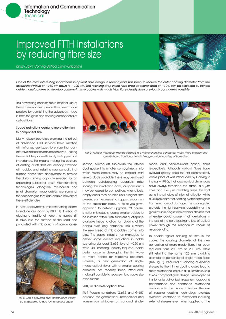
Fig. 1: With a crowded duct infrastructure it may be challenging to add further optical cable.
Fig. 2: A linear microduct may be installed in a microtrench that can be cut much more cheaply and quickly than a traditional trench. (Image on right courtesy of Dura-Line).
EngineerIT – July 2017 65
Sales Tel +2711 521 2370 Cell +2778 280 7115 / +2784 602 0066 Email [email protected] Web www.iclogistix.co.za
SOLE ACCREDITED DISTRIBUTOR FOR SOUTHERN AFRICAN MARKET
QuarterPage IC Logistix July 2017 BOGOF.qxp_Layout 1 2017/06/20 5:43 PM Page 1
Fig. 3: Geometrical differences between conventional single-mode and 200 µ coating fibres.
lower thickness. Note that the glass diameter of 200 µm fibre is unchanged and remains at 125 µm. This is important as it ensures that established industry equipment and procedures for splicing and connectoristion are unchanged, eliminating a potential barrier to wide-scale adoption.
Three sub-categories are defined by the ITU-T G.657 Recommendation; G.657.A1 or “bend improved” fibres, G.657.A2 or “bend tolerant” fibres and G.652.B3 fibres or “bend insensitive” fibres. The bend resistance of each category is also reflected in the microbend tolerance, presenting a dilemma for network owners wanting to take advantage of 200 µm fibres – what category of bend resistance is sufficient to ensure low loss installation? G.657.A1 fibre is intended for use in outside plant and has been widely adopted by network owners [2]. G.657.A2 and G.657.B3 compliant fibres are more commonly used inside the building where much tighter bends on low fibre-count cables are frequently encountered and much greater bend resistance may be required as a consequence. Further, the modified optical core profile design that is frequently used to deliver high bend performance in G.657.A2 and G.657.B3 fibres can result in difficulties when attempting to splice in high volume in the outside plant using established splicing programs and practices. Complemented by a suitably resilient coating material, 200 µm fibre compliant with ITU-T Recommendation G.657.A1 is sufficiently rugged to overcome the microbending challenges presented by a densely-packed micro cable in an outdoor access installation.
Smaller fibre for smaller cables and network
efficiency
The cross-sectional area reduction achieved by migrating from a 250 µm fibre to a 200 µm product is approximately 30%. Equivalent reductions in overall micro cable cross-sectional area for the same fibre-count may
be achieved by designing with the smaller diameter fibre. The improved packing density of the most compact micro cables can deliver benefits in many different ways depending on the characteristics of the network.
lSmaller micro cables enable smaller microducts so more can be packed in the same array. Empty microducts can allow the operator more headroom to grow capacity in future, or may be leased to other operators to generate more revenue immediately. Overall, the limited space is used more efficiently and expansion can be achieved without the large capital investment and disruption of re-digging the road.
lBeing smaller, lighter and more flexible, micro cables can be blown at higher speed and for longer distances, lowering the cost of installation.
lAlternatively, in a crowded existing duct that might otherwise be considered full, micro cables may be blown into the limited space available over practical distances and obviate the need to install new duct.
lSmaller, lighter micro cables can be stored and transported on smaller, lighter drums, which are easier to unload and move into position at the installation site so speeding up installation times.
Conclusion
Recently introduced 200 µm fibres support the need for miniaturisation of FTTH cable and hardware. The higher density micro cable designs that these fibres enable can deliver efficiencies to the network operator both in terms of space utilisation and installation speed, as well as future-proofing against the need for more data-carrying capacity at a later date. The bend resistance of ITU-T recommendation G.657.A1-based 200 µm fibres is sufficient for a wide range of outside plant cable designs and applications and their design is compatible with previously installed cable and established installation equipment and procedures.
References
[1] Network Strategies (2008). "Microtrenching: can it cut the cost of fibre to the home?", Retrieved from www.strategies.nzl.com/wpapers/2008019.html
[2] Mack, R. (2013). Commenting on Ruderman’s “Fibre in Europe bucks economic trends”, Lightwave. Retrieved from www.lightwaveonline.com/articles/2013/01/fibre-in-europe-bucks-economic-trends.html
Contact Rufus Andrew, Corning Optical Communications, Tel 012 244 0890, [email protected]


![Index [] · NEXT GENERATION NETWORK FTTx (FTTH - Fibre to the ... begins at the engineering project planning and design ... of fibre optic networks (FTTN and FTTH),](https://img.pdfslide.us/doc/110x75/5ad676357f8b9a5c638e5def/index-generation-network-fttx-ftth-fibre-to-the-begins-at-the-engineering.jpg)