Embed Size (px)
Citation preview
8/14/2019 Improved Capacitive-Sensing Technology Expands the Realm of Potential Applications
http://slidepdf.com/reader/full/improved-capacitive-sensing-technology-expands-the-realm-of-potential-applications 1/7
Improved Capacitive-sensing Technology Expands the Realm of Potential Applications Page 1 of 7
Improved Capacitive-Sensing Technology Expands the Realm of PotentialApplicationsBy (Ryan Seguine, Product Engineer, Cypress Semiconductor Corp.)
Executive Summary
With all the excitement about capacitive sensing in the portable media player, laptop PC and mobile handset markets, it iseasy to forget that such interface technologies have been actively designed into White Goods applications for years.Significant improvements in sensing algorithms and control circuitry have expanded the suite of applications in which thetechnology can be implemented. Designers are seeing the value of capacitive sensing as a mechanical button and membraneswitch replacement as well as discovering new, exciting applications such as touchscreens and proximity sensors.
Sensing Capacitance
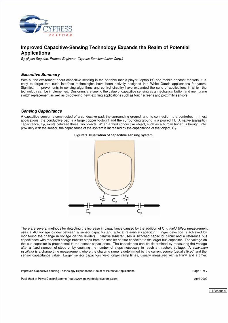
A capacitive sensor is constructed of a conductive pad, the surrounding ground, and its connection to a controller. In mostapplications, the conductive pad is a large copper footprint and the surrounding ground is a poured fill. A native (parasitic)capacitance, CP, exists between these two objects. When a third conductive object, such as a human finger, is brought intoproximity with the sensor, the capacitance of the system is increased by the capacitance of that object, CF.
Figure 1. Illustration of capacitive sensing system.
There are several methods for detecting the increase in capacitance caused by the addition of C F. Field Effect measurementuses a AC voltage divider between a sensor capacitor and a local reference capacitor. Finger detection is achieved bymonitoring the change in voltage on this divider). Charge transfer uses a switched capacitor circuit and a reference buscapacitance with repeated charge transfer steps from the smaller sensor capacitor to the larger bus capacitor. The voltage onthe bus capacitor is proportional to the sensor capacitance. The capacitance can be determined by measuring the voltageafter a fixed number of steps or by counting the number of steps necessary to reach a threshold voltage. A relaxation oscillator is a charge time measurement where the charging ramp is determined by the current source (usually fixed) and thesensor capacitance value. Larger sensor capacitors yield longer ramp times, usually measured with a PWM and a timer.
Published in PowerDesignSystems (http://www.powerdesignsystems.com) April 2007
[+]
8/14/2019 Improved Capacitive-Sensing Technology Expands the Realm of Potential Applications
http://slidepdf.com/reader/full/improved-capacitive-sensing-technology-expands-the-realm-of-potential-applications 2/7
Improved Capacitive-sensing Technology Expands the Realm of Potential Applications Page 2 of 7
Successive Approximation is a capacitance charging time measurement where start voltage is determined by successiveapproximation.
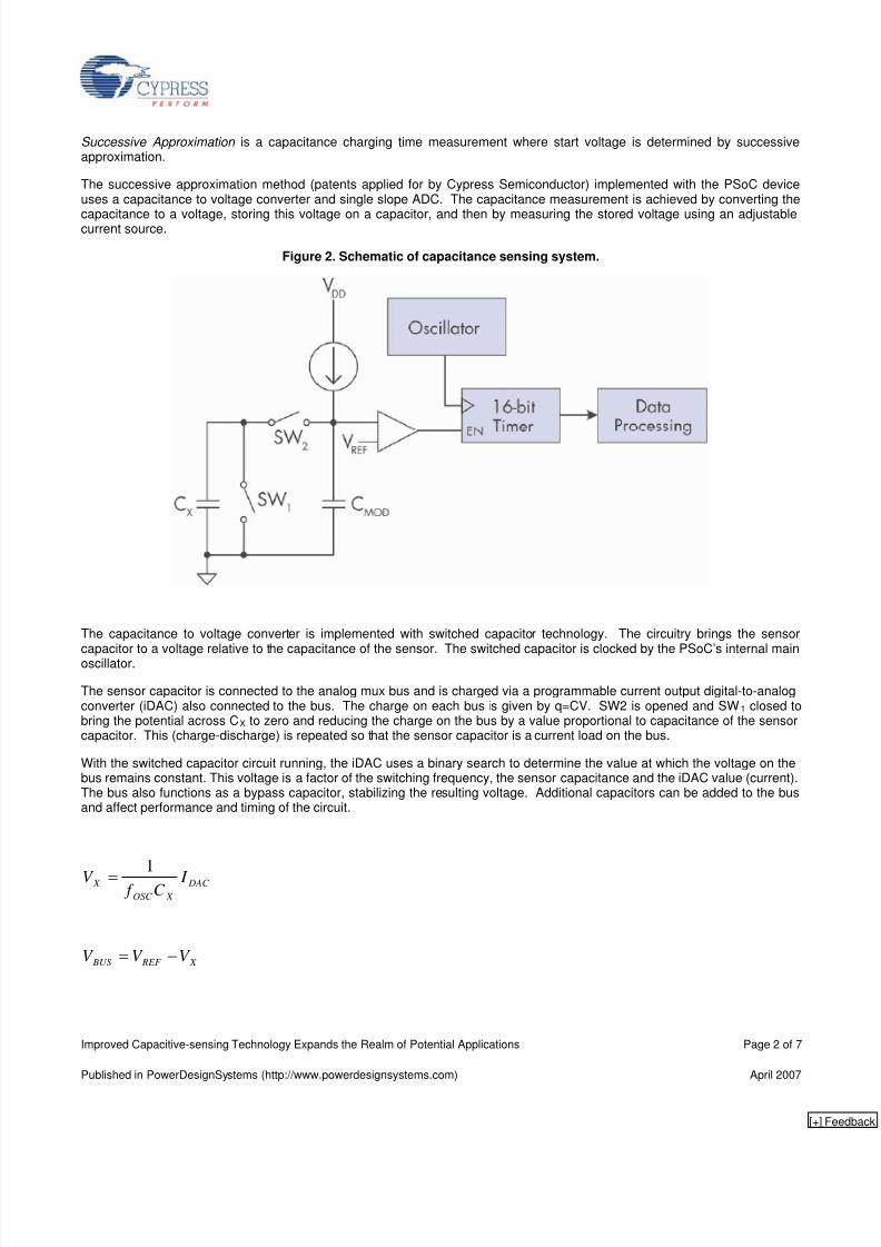
The successive approximation method (patents applied for by Cypress Semiconductor) implemented with the PSoC deviceuses a capacitance to voltage converter and single slope ADC. The capacitance measurement is achieved by converting the
capacitance to a voltage, storing this voltage on a capacitor, and then by measuring the stored voltage using an adjustablecurrent source.
Figure 2. Schematic of capacitance sensing system.
The capacitance to voltage converter is implemented with switched capacitor technology. The circuitry brings the sensor
capacitor to a voltage relative to the capacitance of the sensor. The switched capacitor is clocked by the PSoC’s internal mainoscillator.
The sensor capacitor is connected to the analog mux bus and is charged via a programmable current output digital-to-analogconverter (iDAC) also connected to the bus. The charge on each bus is given by q=CV. SW2 is opened and SW1 closed tobring the potential across CX to zero and reducing the charge on the bus by a value proportional to capacitance of the sensorcapacitor. This (charge-discharge) is repeated so that the sensor capacitor is a current load on the bus.
With the switched capacitor circuit running, the iDAC uses a binary search to determine the value at which the voltage on thebus remains constant. This voltage is a factor of the switching frequency, the sensor capacitance and the iDAC value (current).The bus also functions as a bypass capacitor, stabilizing the resulting voltage. Additional capacitors can be added to the busand affect performance and timing of the circuit.
DAC
X OSC
X I C f
V 1
=
X REF BUS V V V −=
Published in PowerDesignSystems (http://www.powerdesignsystems.com) April 2007
[+]
8/14/2019 Improved Capacitive-Sensing Technology Expands the Realm of Potential Applications
http://slidepdf.com/reader/full/improved-capacitive-sensing-technology-expands-the-realm-of-potential-applications 3/7
Improved Capacitive-sensing Technology Expands the Realm of Potential Applications Page 3 of 7
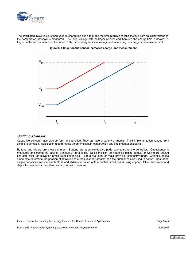
The calculated iDAC value is then used to charge the bus again and the time required to take the bus from an initial voltage tothe comparator threshold is measured. The initial voltage with no finger present and therefore the charge time is known. Afinger on the sensor increases the value of CX, decreasing the initial voltage and increasing the charge time measurement.
Figure 3. A finger on the sensor increases charge time measurement.
Building a Sensor
Capacitive sensors have diverse form and function. They can use a variety of media. Their implementation ranges fromsimple to complex. Application requirements determine sensor construction and implementation details.
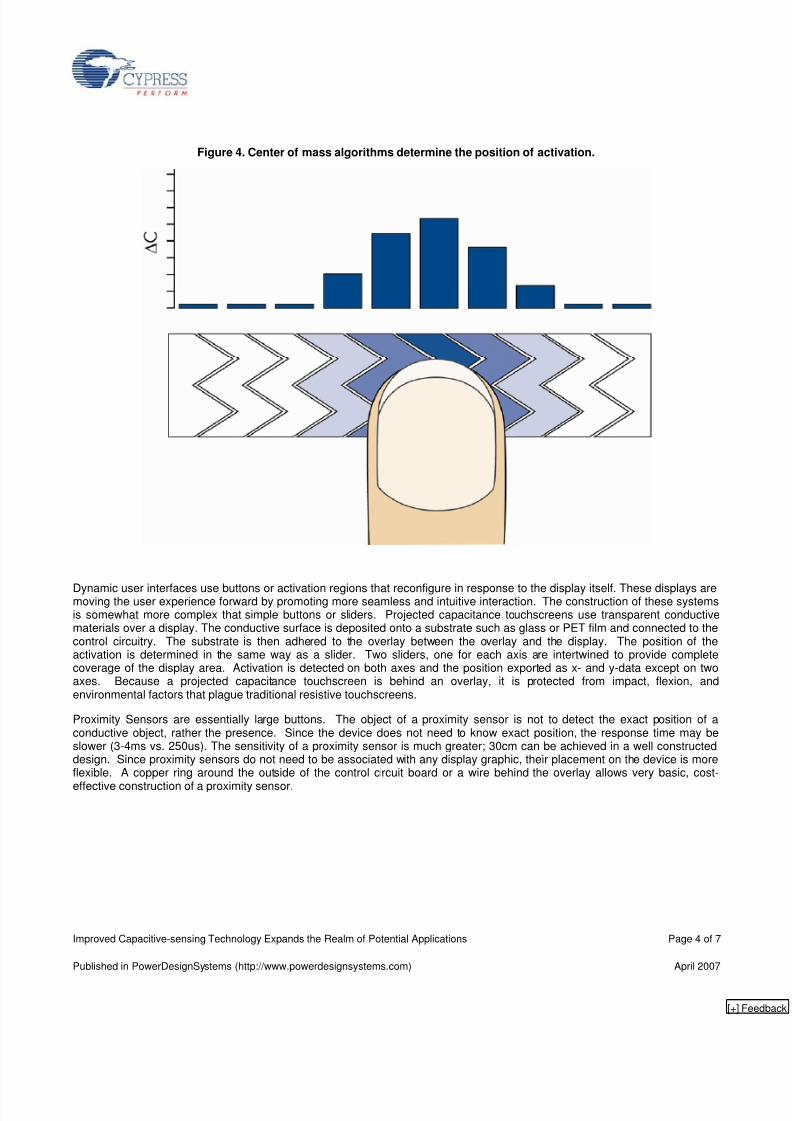
Buttons and sliders are most common. Buttons are large conductive pads connected to the controller. Capacitance ismeasured and compared against a series of thresholds. Decisions can be made as digital outputs or with more analogcharacteristics for activation pressure or finger size. Sliders are linear or radial arrays of conductive pads. Center of massalgorithms determine the position of activation to a resolution far greater than the number of pins used to sense. Most oftensimple capacitive sensors like buttons and sliders deposited onto a printed circuit board using copper. Other substrates anddeposition media such as silver ink can be used, however.
Published in PowerDesignSystems (http://www.powerdesignsystems.com) April 2007
[+]
8/14/2019 Improved Capacitive-Sensing Technology Expands the Realm of Potential Applications
http://slidepdf.com/reader/full/improved-capacitive-sensing-technology-expands-the-realm-of-potential-applications 4/7
Improved Capacitive-sensing Technology Expands the Realm of Potential Applications Page 4 of 7
Figure 4. Center of mass algorithms determine the position of activation.
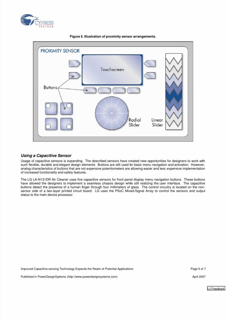
Dynamic user interfaces use buttons or activation regions that reconfigure in response to the display itself. These displays aremoving the user experience forward by promoting more seamless and intuitive interaction. The construction of these systemsis somewhat more complex that simple buttons or sliders. Projected capacitance touchscreens use transparent conductivematerials over a display. The conductive surface is deposited onto a substrate such as glass or PET film and connected to thecontrol circuitry. The substrate is then adhered to the overlay between the overlay and the display. The position of theactivation is determined in the same way as a slider. Two sliders, one for each axis are intertwined to provide completecoverage of the display area. Activation is detected on both axes and the position exported as x- and y-data except on twoaxes. Because a projected capacitance touchscreen is behind an overlay, it is protected from impact, flexion, andenvironmental factors that plague traditional resistive touchscreens.
Proximity Sensors are essentially large buttons. The object of a proximity sensor is not to detect the exact position of aconductive object, rather the presence. Since the device does not need to know exact position, the response time may beslower (3-4ms vs. 250us). The sensitivity of a proximity sensor is much greater; 30cm can be achieved in a well constructeddesign. Since proximity sensors do not need to be associated with any display graphic, their placement on the device is moreflexible. A copper ring around the outside of the control circuit board or a wire behind the overlay allows very basic, cost-
effective construction of a proximity sensor.
Published in PowerDesignSystems (http://www.powerdesignsystems.com) April 2007
[+]
8/14/2019 Improved Capacitive-Sensing Technology Expands the Realm of Potential Applications
http://slidepdf.com/reader/full/improved-capacitive-sensing-technology-expands-the-realm-of-potential-applications 5/7
Improved Capacitive-sensing Technology Expands the Realm of Potential Applications Page 5 of 7
Figure 5. Illustration of proximity sensor arrangements.
Using a Capacitive Sensor
Usage of capacitive sensors is expanding. The described sensors have created new opportunities for designers to work withsuch flexible, durable and elegant design elements. Buttons are still used for basic menu navigation and activation. However,
analog characteristics of buttons that are not expensive potentiometers are allowing easier and less expensive implementationof increased functionality and safety features.
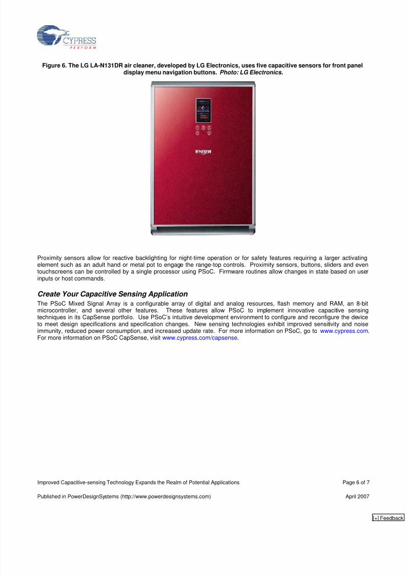
The LG LA-N131DR Air Cleaner uses five capacitive sensors for front panel display menu navigation buttons. These buttonshave allowed the designers to implement a seamless chassis design while still realizing the user interface. The capacitivebuttons detect the presence of a human finger through four millimeters of glass. The control circuitry is located on the non-sensor side of a two-layer printed circuit board. LG uses the PSoC Mixed-Signal Array to control the sensors and outputstatus to the main device processor.
Published in PowerDesignSystems (http://www.powerdesignsystems.com) April 2007
[+]
8/14/2019 Improved Capacitive-Sensing Technology Expands the Realm of Potential Applications
http://slidepdf.com/reader/full/improved-capacitive-sensing-technology-expands-the-realm-of-potential-applications 6/7
Improved Capacitive-sensing Technology Expands the Realm of Potential Applications Page 6 of 7
Figure 6. The LG LA-N131DR air cleaner, developed by LG Electronics, uses five capacitive sensors for front paneldisplay menu navigation buttons. Photo: LG Electronics.
Proximity sensors allow for reactive backlighting for night-time operation or for safety features requiring a larger activatingelement such as an adult hand or metal pot to engage the range-top controls. Proximity sensors, buttons, sliders and eventouchscreens can be controlled by a single processor using PSoC. Firmware routines allow changes in state based on userinputs or host commands.
Create Your Capacitive Sensing Application
The PSoC Mixed Signal Array is a configurable array of digital and analog resources, flash memory and RAM, an 8-bitmicrocontroller, and several other features. These features allow PSoC to implement innovative capacitive sensingtechniques in its CapSense portfolio. Use PSoC’s intuitive development environment to configure and reconfigure the deviceto meet design specifications and specification changes. New sensing technologies exhibit improved sensitivity and noiseimmunity, reduced power consumption, and increased update rate. For more information on PSoC, go to www.cypress.com.For more information on PSoC CapSense, visit www.cypress.com/capsense.
Published in PowerDesignSystems (http://www.powerdesignsystems.com) April 2007
[+]
8/14/2019 Improved Capacitive-Sensing Technology Expands the Realm of Potential Applications
http://slidepdf.com/reader/full/improved-capacitive-sensing-technology-expands-the-realm-of-potential-applications 7/7
Improved Capacitive-sensing Technology Expands the Realm of Potential Applications Page 7 of 7
References
Cypress Semiconductor198 Champion Court
San Jose, CA 95134-1709
Phone: 408-943-2600Fax: 408-943-4730
http://www.cypress.com
© Cypress Semiconductor Corporation, 2007. The information contained herein is subject to change without notice. Cypress Semiconductor Corporation assumes no responsibility for theuse of any circuitry other than circuitry embodied in a Cypress product. Nor does it convey or imply any license under patent or other rights. Cypress products are not warranted nor intendedto be used for medical, life support, life saving, critical control or safety applications, unless pursuant to an express written agreement with Cypress. Furthermore, Cypress does not authorizeits products for use as critical components in life-support systems where a malfunction or failure may reasonably be expected to result in significant injury to the user. The inclusion ofCypress products in life-support systems application implies that the manufacturer assumes all risk of such use and in doing so indemnifies Cypress against all charges.
PSoC Designer™, Programmable System-on-Chip™, and PSoC Express™ are trademarks and PSoC® is a registered trademark of Cypress Semiconductor Corp. All other trademarks orregistered trademarks referenced herein are property of the respective corporations.
This Source Code (software and/or firmware) is owned by Cypress Semiconductor Corporation (Cypress) and is protected by and subject to worldwide patent protection (United States andforeign), United States copyright laws and international treaty provisions. Cypress hereby grants to licensee a personal, non-exclusive, non-transferable license to copy, use, modify, createderivative works of, and compile the Cypress Source Code and derivative works for the sole purpose of creating custom software and or firmware in support of licensee product to be usedonly in conjunction with a Cypress integrated circuit as specified in the applicable agreement. Any reproduction, modification, translation, compilation, or representation of this Source Codeexcept as specified above is prohibited without the express written permission of Cypress.
Disclaimer: CYPRESS MAKES NO WARRANTY OF ANY KIND, EXPRESS OR IMPLIED, WITH REGARD TO THIS MATERIAL, INCLUDING, BUT NOT LIMITED TO, THE IMPLIEDWARRANTIES OF MERCHANTABILITY AND FITNESS FOR A PARTICULAR PURPOSE. Cypress reserves the right to make changes without further notice to the materials describedherein. Cypress does not assume any liability arising out of the application or use of any product or circuit described herein. Cypress does not authorize its products for use as criticalcomponents in life-support systems where a malfunction or failure may reasonably be expected to result in significant injury to the user. The inclusion of Cypress’ product in a life-supportsystems application implies that the manufacturer assumes all risk of such use and in doing so indemnifies Cypress against all charges.
Use may be limited by and subject to the applicable Cypress software license agreement.
Published in PowerDesignSystems (http://www.powerdesignsystems.com) April 2007