Embed Size (px)
Citation preview
Impression Rail™ Express
Installation Guide
Aluminum Posts ............................4
Level Panels ...................................8
Stair Panels .................................. 11
TimberTech.com
Open Mid-Rail
Page 2
Installing Impression Rail™ Express
Open Mid-Rail Aluminum Railing System
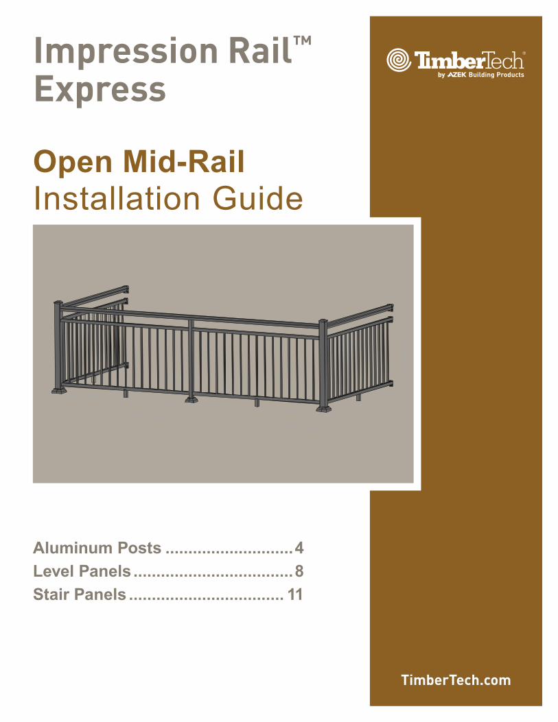
Standard Open Mid-Rail System Each Panel Requires:
• 36" X 6' Panel Kit
• One additional Bottom Snap
• One unpunched H-Channel
• Rail Attach Kit (one kit for two panels)
• 6 Deck Rail Clips per bay
Continuous Top Rail Open Mid-Rail System Each Panel Requires:
• 36" X 6' or 8' Continuous Top Rail Panel Kits
• One additional Bottom Snap
• One unpunched H-Channel
• Rail Attach Kit (one kit for two panels)
• Continuous Top Rail (span up to 18')
• 5 Deck Rail Clips per bay
• One Crossover Bracket
Important Note:
Prior to construction, check with your local regulatory agency for special code requirements in your area.Common railing height is 36" or 42". Post spans will vary depending on job site conditions. Never span more than 8' on-center between railing posts. Spans longer than 12' in length will require reduced post spans. When you cut a kit to create two panels, for instance, cutting 8' to two 4', you will need an additional hardware kit. Read instructions completely to get an understanding of how the product goes together and how each piece affects the other.
Important Information
• Please read all instructions completely before starting any part of the installation. Always make sure to visit www.TimberTech.com to
ensure you are viewing the most current installation instructions, care and cleaning, technical information and more.
• Impression Rail Express should be installed using the same good building principles used to install wood, composite, or metal railing and
in accordance with the local building codes and the installation guidelines included below.
• The AZEK Co. LLC accepts no liability or responsibility for the improper installation of this product.
• Impression Rail Express may not be suitable for every application and it is the sole responsibility of the installer to be sure that Impression
Rail is fit for the intended use. Since all installations are unique, it is also the installer’s responsibility to determine specific requirements in regards to each rail application.
• The AZEK Co. LLC recommends that all applications be reviewed by a licensed architect, engineer or local building official before installation. If you have any questions or need further assistance, please call AZEK Customer Service at 877-ASK-AZEK (877-275-2935),
or visit our website at www.TimberTech.com.
• Impression Rail Express is tested as a whole system and should be used that way. It is not intended to be used in conjunction with other
railing systems or fasteners.
• The following Installation Guidelines are applicable for installation of Impression Rail Express only.
• IMPORTANT: Make sure the DRIVE TOOL/DRILL is configured or set to use the SCREW setting when driving and/or tightening all FASTENERS.
• SAFETY: Always wear goggles when handling, cutting, drilling and fastening materials.
• Failure to install this product in accordance with applicable building codes and Impression Rail Express’s written Rail Install Guide may lead to personal injury, affect rail system performance and void the product warranty.
• The buildup or generation of static electricity is a naturally occurring phenomenon in many plastic based products such as carpeting,
upholstery, and clothing, and can occur on alternative decking under certain environmental conditions. This static electricity can discharge
once contact is made with hardware, railing, or other conductors of electricity.
Page 3
Installing Impression Rail™ Express
Open Mid-Rail Aluminum Railing System
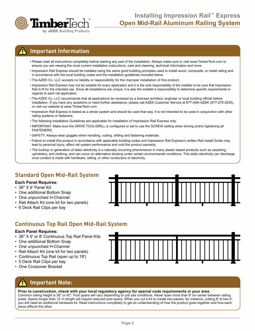
36" X 6' STAIRPANEL KIT
STAIR PANEL ATTACHKIT REQUIRED WHENSTAIR PANEL IS CUT& USED AS 2-PIECES
ENSUREPROPER
BLOCKING 3" X 42" POST/BASE KITON DECK SURFACE
PANEL ATTACH KITREQUIRED WHEN DECKPANELS ARE CUT & USED AS 2-PIECES
GATE KIT
STRAIGHT WALLMOUNT KIT
ENSUREPROPERBLOCKING
(4) 3/8” X 6” GRK RSS STRUCTURAL SCREWS
(SOLD SEPARATELY)
36" X 6'PANEL KIT
*CAUTION*45 CORNERSPOST MUSTBISECT CORNER& USE 22.5 KIT
22.5 PANEL ATTACH KIT(USE FOR 45 CORNERS)
42" POST/BASE KITON ALL STAIR TREADS
2" X 42" CENTER POST
2" X 42" CENTER POST
CONTINUOUS TOP RAIL
DET. PLAN VIEW
REF 45 CORNER
**CONCRETE APPLICATIONS**WHEN POSTS ARE SECURED TO CONCRETESUBSTRATES USE CONCRETE ANCHORS(SOLD SEPARATELY)
NOTE: IF INSTALLING POST LIGHTING, WIRING MUST BE
INSTALLED PRIOR TO SECURING POSTS TO DECK/STAIR
SURFACE AND INSTALLING TOP RAIL SNAPS.
It is the responsibility of the installer to meet all local code
requirements and obtain all required building permits.
The installer should determine and implement appropriate
installation techniques for each installation situation.
AZEK Co. LLC or its reseller shall not be held responsible
for improper or unsafe installations.
Suggested Tools:
• Appropriate fasteners
for mounting posts to
deck
• Miter saw with carbide-
tipped non-ferrous
blade
• Cordless drill
• Tape measure
• Level
• Power cords, drop
sheets and safety
glasses
• 3/16" Drill bit
• 6" #2 Square drive bit
• Installation jig (optional)
Important Note:
42" posts and 36" high railing panels (34" actual size)
are required to build 42" high Open Mid-Rail System
on a level surface. 48" posts are required for stair
applications.
Important Note:
Actual Level Panel Lengths Are As Follows:
• 6' Panels = 69.43"
• 8' Panels = 91.31"
• 3" posts are required to reach 6' & 8' lengths
Page 4
Installing Impression Rail™ Express
Aluminum Posts
Dia. #4
2
Cap
Square Post
Post Base Plate Vinyl Cover
*Do not install until railing assembly is completed.
Deck Edge
Joist
Stringer2x6 Blocking
2x6 Cross
Block
Shims
below
base
2x6 Blocking
4X 3/8"x6" construction lag
screws (sold separately)
*Verify local code
requirements for post
attachment hardware.
Dia. #3B(SIDE VIEW)
Dia. #3A(TOP VIEW)
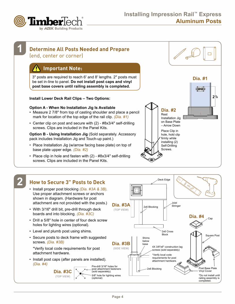
How to Secure 3" Posts to Deck• Install proper post blocking (Dia. #3A & 3B).
Use proper attachment screws or anchors
shown in diagram. (Hardware for post
attachment are not provided with the posts.)
• With 3/16″ drill bit, pre-drill through deck boards and into blocking. (Dia. #3C)
• Drill a 5/8" hole in center of four deck screw
holes for lighting wires (optional).
• Level and plumb post using shims.
• Secure posts to deck frame with suggested
screws. (Dia. #3B)
*Verify local code requirements for post
attachment hardware.
• Install post caps (after panels are installed).
(Dia. #4)Pre-drill 3/16" holes for post attachment fasteners (sold separately).
5/8" hole for lighting wires (optional)
Dia. #3C(TOP VIEW)
Determine All Posts Needed and Prepare (end, center or corner)
Important Note:
3" posts are required to reach 6' and 8' lengths. 2" posts must
be set in-line to panel. Do not install post caps and vinyl
post base covers until railing assembly is completed.
Install Lower Deck Rail Clips – Two Options:
Option A - When No Installation Jig Is Available
• Measure 2 7/8" from top of casting shoulder and place a pencil
mark for location of the top edge of the rail clip. (Dia. #1)
• Center clip on post and secure with (2) - #8x3/4" self-drilling
screws. Clips are included in the Panel Kits.
Option B - Using Installation Jig (Sold separately. Accessory
pack includes Installation Jig and Touch-up paint.)
• Place Installation Jig (w/arrow facing base plate) on top of
base plate upper edge. (Dia. #2)
• Place clip in hole and fasten with (2) - #8x3/4" self-drilling
screws. Clips are included in the Panel Kits.
1
Dia. #1
Rest
Installation Jig
on Base Plate
– Arrow Down
Place Clip in
hole, hold clip
firmly while installing (2)
Self-Drilling
Screws.
Dia. #2
Page 5
Installing Impression Rail™ Express
Aluminum Posts
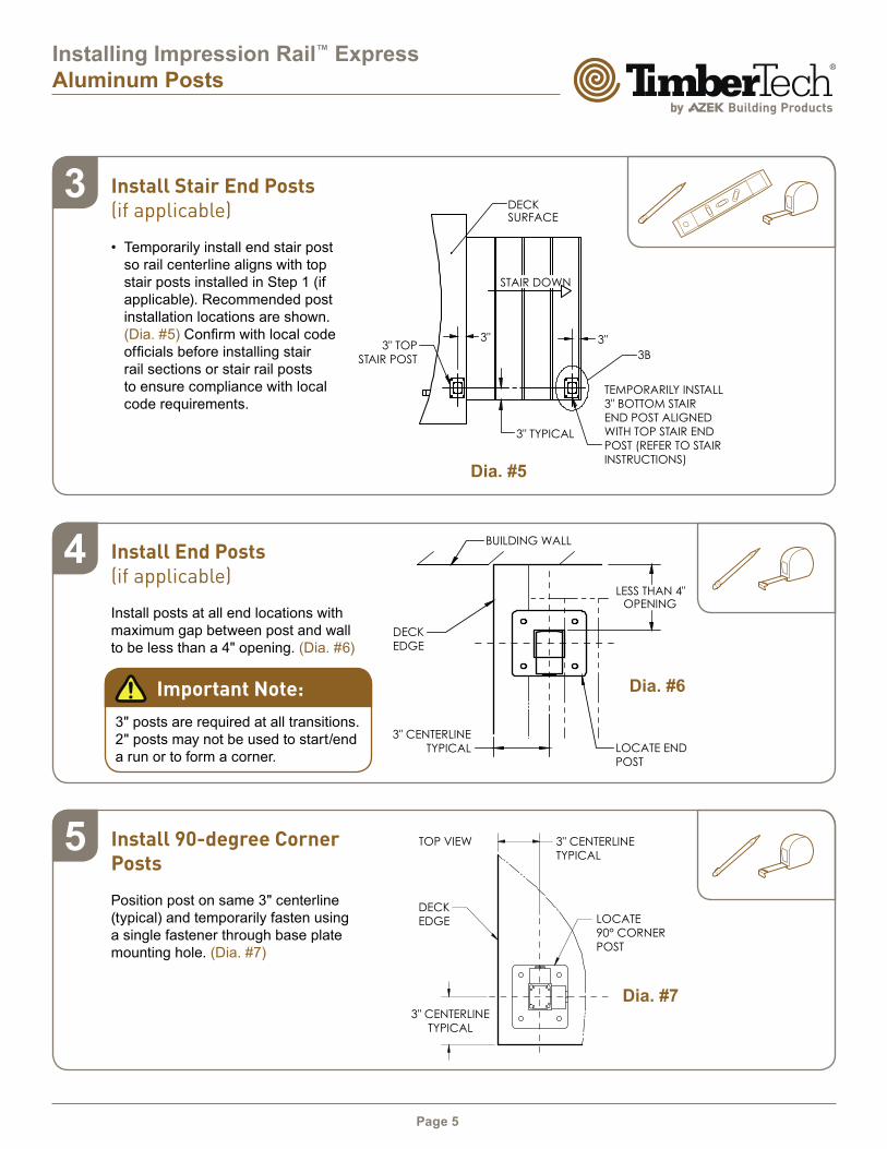
Install Stair End Posts (if applicable)
• Temporarily install end stair post
so rail centerline aligns with top
stair posts installed in Step 1 (if
applicable). Recommended post
installation locations are shown.
(Dia. #5) Confirm with local code officials before installing stair rail sections or stair rail posts
to ensure compliance with local
code requirements.
Install End Posts (if applicable)
Install posts at all end locations with
maximum gap between post and wall
to be less than a 4" opening. (Dia. #6)
Install 90-degree Corner Posts
Position post on same 3" centerline
(typical) and temporarily fasten using
a single fastener through base plate
mounting hole. (Dia. #7)
3
4
5
Dia. #6
Dia. #7
Important Note:
3" posts are required at all transitions.
2" posts may not be used to start/end
a run or to form a corner.
Dia. #5
3"3"
3" TYPICAL
3B
DECKSURFACE
STAIR DOWN
3" TOP
STAIR POST
TEMPORARILY INSTALL
3" BOTTOM STAIR
END POST ALIGNED
WITH TOP STAIR END
POST (REFER TO STAIR
INSTRUCTIONS)
OPENINGLESS THAN 4"
3" CENTERLINE
TYPICAL
DECK
EDGE
BUILDING WALL
LOCATE END
POST
TOP VIEW 3" CENTERLINE
TYPICAL
LOCATE
90° CORNER
POST
3" CENTERLINE
TYPICAL
DECK
EDGE
Page 6
Installing Impression Rail™ Express
Aluminum Posts
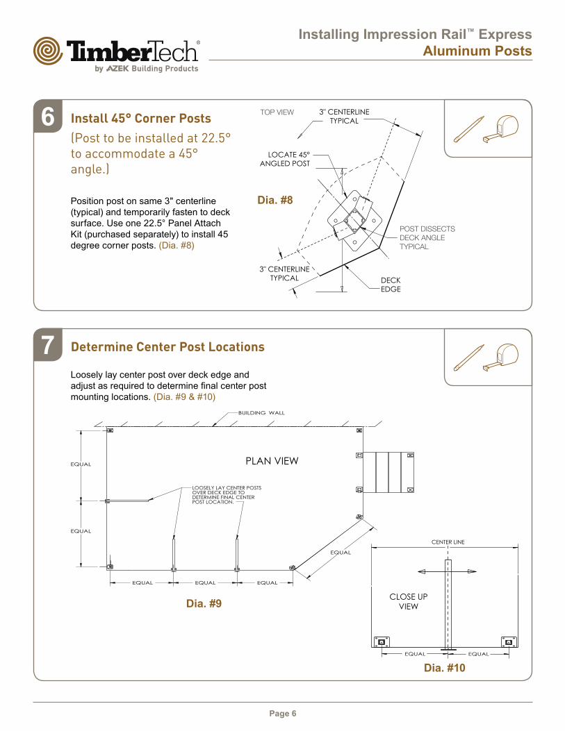
Determine Center Post Locations
Loosely lay center post over deck edge and
adjust as required to determine final center post mounting locations. (Dia. #9 & #10)
7
Dia. #9
Dia. #10
PLAN VIEW
CLOSE UP
VIEW
CENTER LINE
Install 45° Corner Posts
(Post to be installed at 22.5° to accommodate a 45° angle.)
Position post on same 3" centerline
(typical) and temporarily fasten to deck
surface. Use one 22.5° Panel Attach
Kit (purchased separately) to install 45
degree corner posts. (Dia. #8)
6
Dia. #8
TOP VIEW
POST DISSECTS
DECK ANGLE
TYPICAL
DECK
EDGE
3" CENTERLINE
TYPICAL
3" CENTERLINE
TYPICAL
LOCATE 45°
ANGLED POST

Page 7
Installing Impression Rail™ Express
Aluminum Posts
STAIR CROSSOVER
BRACKET
POST BASE PLATE
VINYL COVER
POST
EXTRUSION
CLIP
Dia. #12B
Dia. #12D
Install Crossover Brackets on 2" Posts
• With 6" #2 square drive bit, fasten straight crossover bracket (included) into post with
(2) - #8x1.5" Self-Drilling Screws. (Dia. #12A & #12B)
NOTE: Self-Drilling Screws must be installed in screw chases in-line with panels.
• With 6" #2 square drive bit, fasten H-channel to straight and stair crossover brackets
with (4) - #8x3/4" Self-Drilling Screws. (Dia. #12C & #12D) Repeat for lower clips.
• Install base plate vinyl cover only after railing assembly is completed. (Dia. #4)
8
9
Dia. #11
3" CENTERLINE TYPICAL DECK EDGE
Secure 2" Posts to Deck (center only)
• For continuous top rail systems, install 2" posts centered between
3" end and corner posts.
NOTE: 2" Posts must be installed with center screw chases
in-line with panel (Dia. #11).
• Follow instructions in step 2 (Dia. #3A to Dia. #4).
Important Note:
3" posts are required at all transitions. 2" posts may not be used
to start/end a run or to form a corner.
STRAIGHT CROSSOVER
BRACKET
POST BASE PLATE VINYL COVER
*DO NOT INSTALL UNTIL RAILING
ASSEMBLY IS COMPLETED.
POST
EXTRUSION
CLIP
Dia. #12A
Dia. #12C
LEVEL PANELS
STAIR PANELS
Page 8
Installing Impression Rail™ Express
Open Mid-Rail Level Panels
Dia. #1
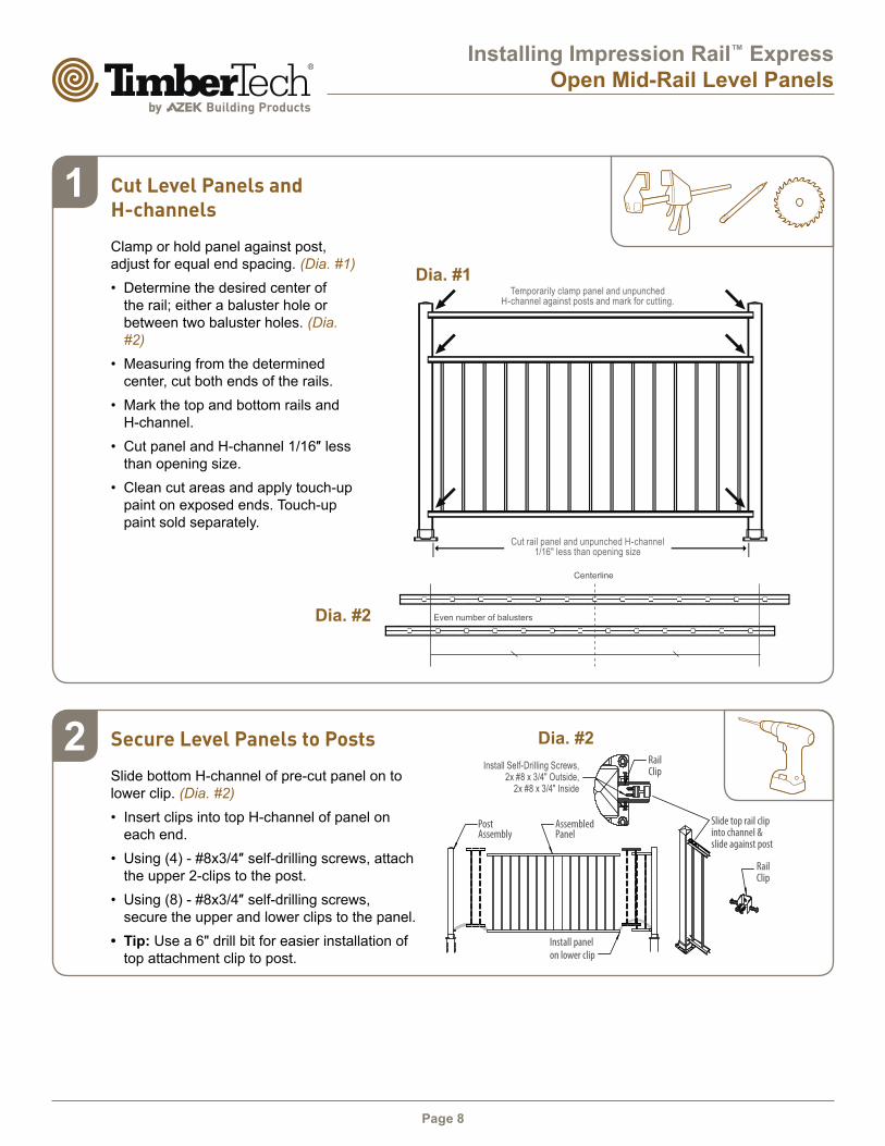
Dia. #2Secure Level Panels to Posts
Slide bottom H-channel of pre-cut panel on to
lower clip. (Dia. #2)
• Insert clips into top H-channel of panel on
each end.
• Using (4) - #8x3/4″ self-drilling screws, attach the upper 2-clips to the post.
• Using (8) - #8x3/4″ self-drilling screws, secure the upper and lower clips to the panel.
• Tip: Use a 6" drill bit for easier installation of
top attachment clip to post.
Cut Level Panels and H-channels
Clamp or hold panel against post,
adjust for equal end spacing. (Dia. #1)
• Determine the desired center of
the rail; either a baluster hole or
between two baluster holes. (Dia.
#2)
• Measuring from the determined
center, cut both ends of the rails.
• Mark the top and bottom rails and
H-channel.
• Cut panel and H-channel 1/16″ less than opening size.
• Clean cut areas and apply touch-up
paint on exposed ends. Touch-up
paint sold separately.
2
1
Cut rail panel and unpunched H-channel 1/16" less than opening size
Temporarily clamp panel and unpunched H-channel against posts and mark for cutting.
Dia. #2
Centerline
Even number of balusters
Install Self-Drilling Screws,2x #8 x 3/4" Outside,
2x #8 x 3/4" Inside
Page 9
Installing Impression Rail™ Express
Open Mid-Rail Level Panels
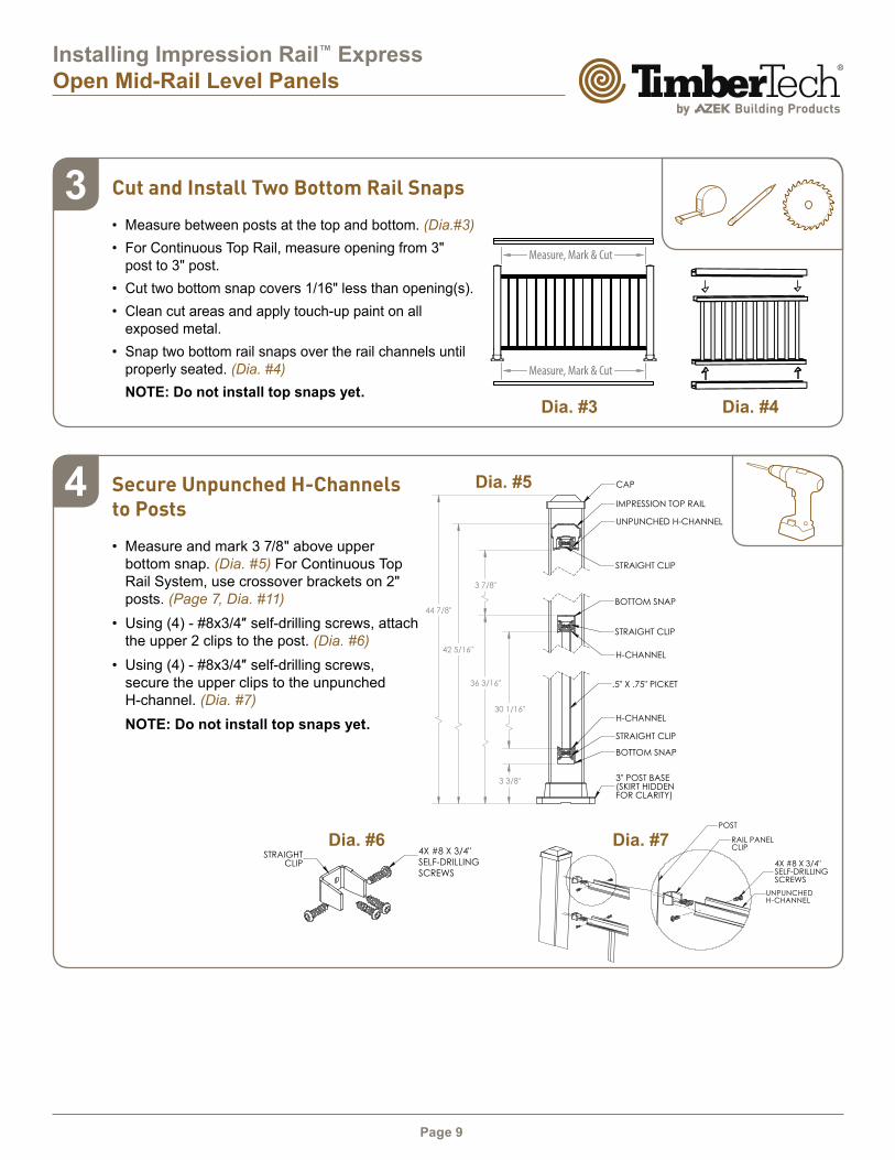
Secure Unpunched H-Channels to Posts
• Measure and mark 3 7/8" above upper
bottom snap. (Dia. #5) For Continuous Top
Rail System, use crossover brackets on 2"
posts. (Page 7, Dia. #11)
• Using (4) - #8x3/4″ self-drilling screws, attach the upper 2 clips to the post. (Dia. #6)
• Using (4) - #8x3/4″ self-drilling screws, secure the upper clips to the unpunched
H-channel. (Dia. #7)
NOTE: Do not install top snaps yet.
Cut and Install Two Bottom Rail Snaps
• Measure between posts at the top and bottom. (Dia.#3)
• For Continuous Top Rail, measure opening from 3"
post to 3" post.
• Cut two bottom snap covers 1/16" less than opening(s).
• Clean cut areas and apply touch-up paint on all
exposed metal.
• Snap two bottom rail snaps over the rail channels until
properly seated. (Dia. #4)
NOTE: Do not install top snaps yet.
4
3
Dia. #3 Dia. #4
3" POST DETAIL
3" X 3"POST CAP
MOUNTINGSTRUCTURE
4X BASEMOUNTINGSCREWS
3" POSTBASE
RAIL PANEL CLIP DETAIL
RAIL PANEL
BOTTOM RAIL WALL MOUNT
2X WALL MOUNTING
SCREWS
IMPRESSION WALL MOUNT
WALL MOUNT DETAIL
2X WALL MOUNTINGSCREWS
MOUNTINGSTRUCTURE
BOTTOM RAIL WALL MOUNT
2X WALL MOUNTING
SCREWS
POST
H-CHANNEL
RAIL PANELCLIP
4X #8 X 3/4"TEK SCREWS
2" POST DETAIL
CROSSOVERBRACKET
4X BASEMOUNTINGSCREWS
MOUNTINGSTRUCTURE
2" POST
2" POSTBASE
2" BASESKIRT
SHEET 2 OF 2PROPRIETARY AND CONFIDENTIAL
THE INFORMATION CONTAINED IN THIS DRAWING IS THE SOLE PROPERTY OF UltraLox. ANY REPRODUCTION IN PART OR AS A WHOLE WITHOUT THE WRITTEN PERMISSION OF UltraLox IS NOT PERMITTED.
UNPUNCHED H-CHANNEL
4X #8 X 3/4"SELF-DRILLING SCREWS
77.43 OUTSIDE OF SKIRTS
75.44 OUTSIDE OF POSTS 75.70 OUTSIDE OF CAPS
69.44 INSIDE OF POSTS
3.88 TYP
A
ASUPPORT LEG
SKIRT
3" END POSTS
30.06
3.36
44.78
36.20
3.88
42.33
SECTION A-A
CAP
IMPRESSION TOP RAIL
H-CHANNEL
STRAIGHT CLIP
BOTTOM SNAP
H-CHANNEL
STRAIGHT CLIP
3" POST BASE(SKIRT HIDDEN FOR CLARITY)
UNPUNCHED H-CHANNEL
STRAIGHT CLIP
BOTTOM SNAP
.5" X .75" PICKET
6X CLIP DETAIL
4X #8 X 3/4"TEK SCREWSTRAIGHT
CLIP
NOTES:1. ALL RAIL MUST BE ASSEMBLED AND FASTENED IN ACCORDANCE WITH ULTRALOX'S INSTALLATION INSTRUCTIONS.2. AVAILABLE COLORS ARE BLACK - WHITE - BRONZE.
REVISIONS - BALLOONS DENOTE CHANGES
REV. DESCRIPTION DATE APPROVED
A 7/31/2018 ZAG
A A
B B
4
4
3
3
2
2
1
1
SHOP DRAWING,IMPRESSION TOP RAIL,
3" END POSTS, 36" PICKETS, OPEN MIDRAIL,
6' SECTION
ADO NOT SCALE DRAWING SHEET 1 OF 1
7/31/18ZAG
UNLESS OTHERWISE SPECIFIED:
SCALE: 1:10 WEIGHT:
REVDWG. NO.
BSIZE
TITLE:
NAME DATE
MFG APPR.
ENG APPR.
CHECKED
DRAWN
FINISH
MATERIAL
INTERPRET GEOMETRICTOLERANCING PER: ASME Y14.5-2009
DIMENSIONS ARE IN INCHESTOLERANCES:SURFACE FINISH: 125 RMSANGULAR: .5 DEGLINEAR: .X .02 .XX .010 .XXX .005
PROPRIETARY AND CONFIDENTIALTHE INFORMATION CONTAINED IN THISDRAWING IS THE SOLE PROPERTY OFUltraLox. ANY REPRODUCTION IN PARTOR AS A WHOLE WITHOUT THE WRITTENPERMISSION OF UltraLox.
THIRD ANGLEPROJECTION:
A
Dia. #5
44 7/8"
42 5/16"
36 3/16"
30 1/16"
3 3/8"
3 7/8"
Dia. #7
77.43 OUTSIDE OF SKIRTS
75.44 OUTSIDE OF POSTS 75.70 OUTSIDE OF CAPS
69.44 INSIDE OF POSTS
3.88 TYP
A
ASUPPORT LEG
SKIRT
3" END POSTS
30.06
3.36
44.78
36.20
3.88
42.33
SECTION A-A
CAP
IMPRESSION TOP RAIL
H-CHANNEL
STRAIGHT CLIP
BOTTOM SNAP
H-CHANNEL
STRAIGHT CLIP
3" POST BASE(SKIRT HIDDEN FOR CLARITY)
UNPUNCHED H-CHANNEL
STRAIGHT CLIP
BOTTOM SNAP
.5" X .75" PICKET
6X CLIP DETAIL
4X #8 X 3/4"TEK SCREWSTRAIGHT
CLIP
NOTES:1. ALL RAIL MUST BE ASSEMBLED AND FASTENED IN ACCORDANCE WITH ULTRALOX'S INSTALLATION INSTRUCTIONS.2. AVAILABLE COLORS ARE BLACK - WHITE - BRONZE.
REVISIONS - BALLOONS DENOTE CHANGES
REV. DESCRIPTION DATE APPROVED
A 7/31/2018 ZAG
A A
B B
4
4
3
3
2
2
1
1
SHOP DRAWING,IMPRESSION TOP RAIL,
3" END POSTS, 36" PICKETS, OPEN MIDRAIL,
6' SECTION
ADO NOT SCALE DRAWING SHEET 1 OF 1
7/31/18ZAG
UNLESS OTHERWISE SPECIFIED:
SCALE: 1:10 WEIGHT:
REVDWG. NO.
BSIZE
TITLE:
NAME DATE
MFG APPR.
ENG APPR.
CHECKED
DRAWN
FINISH
MATERIAL
INTERPRET GEOMETRICTOLERANCING PER: ASME Y14.5-2009
DIMENSIONS ARE IN INCHESTOLERANCES:SURFACE FINISH: 125 RMSANGULAR: .5 DEGLINEAR: .X .02 .XX .010 .XXX .005
PROPRIETARY AND CONFIDENTIALTHE INFORMATION CONTAINED IN THISDRAWING IS THE SOLE PROPERTY OFUltraLox. ANY REPRODUCTION IN PARTOR AS A WHOLE WITHOUT THE WRITTENPERMISSION OF UltraLox.
THIRD ANGLEPROJECTION:
A
Dia. #64X #8 X 3/4"
SELF-DRILLING
SCREWS
Page 10
Installing Impression Rail™ Express
Open Mid-Rail Level Panels
Dia. #8
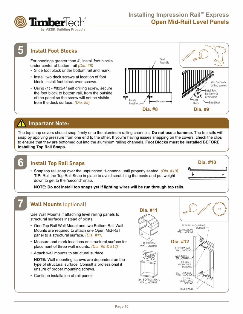
Install Foot Blocks
For openings greater than 4', install foot blocks
under center of bottom rail (Dia. #8)
• Slide foot block under bottom rail and mark.
• Install two deck screws at location of foot
block, install foot block over screws.
• Using (1) - #8x3/4” self drilling screw, secure
the foot block to bottom rail, from the outside
of the panel so the screw will not be visible
from the deck surface. (Dia. #9)
5
Dia. #9
#8 x 3/4" self-drilling screws
Locate
Foot Block
Foot
Block
Install Foot
Block over 2x
deck screws
Important Note:
The top snap covers should snap firmly onto the aluminum railing channels. Do not use a hammer. The top rails will
snap by applying pressure from one end to the other. If you’re having issues snapping on the covers, check the clips to ensure that they are bottomed out into the aluminum railing channels. Foot Blocks must be installed BEFORE
installing Top Rail Snaps.
Dia. #10Install Top Rail Snaps
• Snap top rail snap over the unpunched H-channel until properly seated. (Dia. #10)
TIP: Roll the Top Rail Snap in place to avoid scratching the posts and put weight
down to get to the “second” snap.
NOTE: Do not install top snaps yet if lighting wires will be run through top rails.
6
3" POST DETAIL
3" X 3"POST CAP
MOUNTINGSTRUCTURE
4X BASEMOUNTINGSCREWS
3" POSTBASE
RAIL PANEL CLIP DETAIL
RAIL PANEL
BOTTOM RAIL WALL MOUNT
2X WALL MOUNTING
SCREWS
IMPRESSION WALL MOUNT
WALL MOUNT DETAIL
2X WALL MOUNTINGSCREWS
MOUNTINGSTRUCTURE
BOTTOM RAIL WALL MOUNT
2X WALL MOUNTING
SCREWS
POST
H-CHANNEL
RAIL PANELCLIP
4X #8 X 3/4"TEK SCREWS
2" POST DETAIL
CROSSOVERBRACKET
4X BASEMOUNTINGSCREWS
MOUNTINGSTRUCTURE
2" POST
2" POSTBASE
2" BASESKIRT
SHEET 2 OF 2PROPRIETARY AND CONFIDENTIAL
THE INFORMATION CONTAINED IN THIS DRAWING IS THE SOLE PROPERTY OF UltraLox. ANY REPRODUCTION IN PART OR AS A WHOLE WITHOUT THE WRITTEN PERMISSION OF UltraLox IS NOT PERMITTED.
Wall Mounts (optional)
Use Wall Mounts if attaching level railing panels to
structural surfaces instead of posts.
• One Top Rail Wall Mount and two Bottom Rail Wall
Mounts are required to attach one Open Mid-Rail
panel to a structural surface. (Dia. #11)
• Measure and mark locations on structural surface for
placement of three wall mounts. (Dia. #5 & #12)
• Attach wall mounts to structural surface.
NOTE: Wall mounting screws are dependent on the
type of structural surface. Consult a professional if
unsure of proper mounting screws.
• Continue installation of rail panels
7
Dia. #12
ISOMETRIC VIEW
BOTTOM RAILWALL MOUNT
(PART NUMBER VARIESBY COLOR)
IMPRESSIONWALL MOUNT
(PART NUMBER VARIESBY COLOR)
2.25
2.50
IMPRESSIONTOP RAIL
(PART NUMBER VARIESBY LENGTH AND COLOR)
SHEET 1 OF 2
PICKET RAIL WITH OPEN MID-RAIL,3" POSTS, 2" CENTER POST, WALL MOUNTED
PROPRIETARY AND CONFIDENTIALTHE INFORMATION CONTAINED IN THIS DRAWING IS THE SOLE PROPERTY OF UltraLox.
ANY REPRODUCTION IN PART OR AS A WHOLE WITHOUT THE WRITTEN PERMISSION OF UltraLox IS NOT PERMITTED.
PART REFERENCE
(1X) TOP RAIL WALL MOUNT
(2X) BOTTOM RAIL WALL MOUNT
Dia. #11
Page 11
Installing Impression Rail™ Express
Open Mid-Rail Stair Panels
UPPER BOTTOM SNAP
LOWER
BOTTOM SNAP
STAIR
PANEL
STAIR PANEL
ATACH CLIPS
UNPUNCHED H-CHANNEL
AND TOP SNAP
3” POST KIT
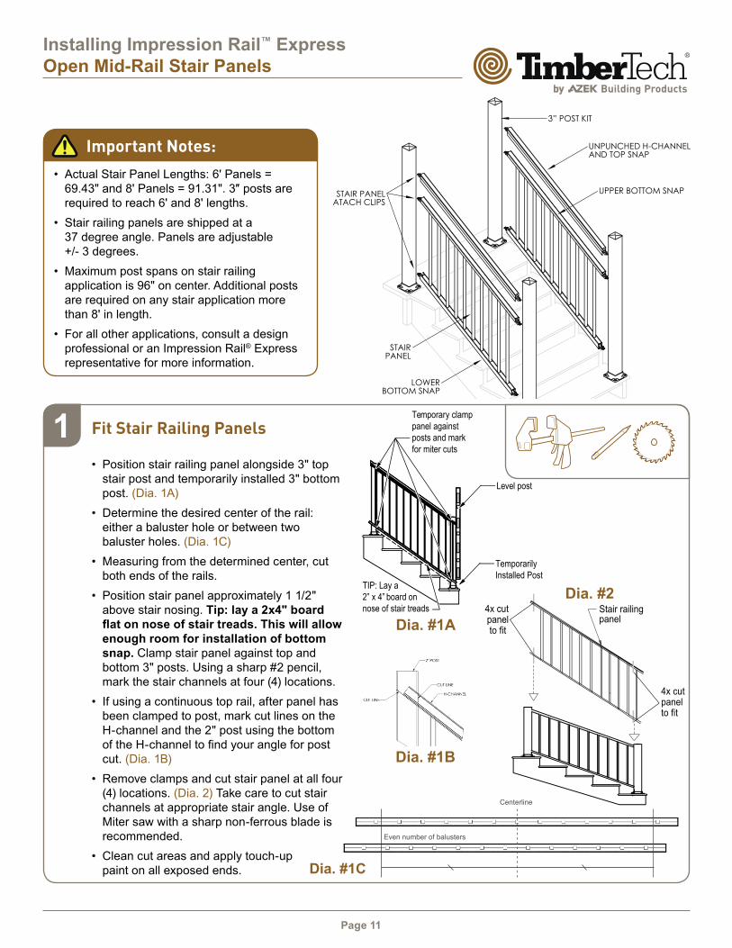
Important Notes:
• Actual Stair Panel Lengths: 6' Panels =
69.43" and 8' Panels = 91.31". 3″ posts are required to reach 6' and 8' lengths.
• Stair railing panels are shipped at a
37 degree angle. Panels are adjustable
+/- 3 degrees.
• Maximum post spans on stair railing
application is 96" on center. Additional posts
are required on any stair application more
than 8' in length.
• For all other applications, consult a design
professional or an Impression Rail® Express
representative for more information.
Dia. #1A
Dia. #2
1 Fit Stair Railing Panels
• Position stair railing panel alongside 3" top
stair post and temporarily installed 3" bottom
post. (Dia. 1A)
• Determine the desired center of the rail:
either a baluster hole or between two
baluster holes. (Dia. 1C)
• Measuring from the determined center, cut
both ends of the rails.
• Position stair panel approximately 1 1/2"
above stair nosing. Tip: lay a 2x4" board
flat on nose of stair treads. This will allow enough room for installation of bottom
snap. Clamp stair panel against top and
bottom 3" posts. Using a sharp #2 pencil,
mark the stair channels at four (4) locations.
• If using a continuous top rail, after panel has
been clamped to post, mark cut lines on the
H-channel and the 2" post using the bottom
of the H-channel to find your angle for post cut. (Dia. 1B)
• Remove clamps and cut stair panel at all four
(4) locations. (Dia. 2) Take care to cut stair
channels at appropriate stair angle. Use of
Miter saw with a sharp non-ferrous blade is
recommended.
• Clean cut areas and apply touch-up
paint on all exposed ends.
4x cut panelto fit
4x cutpanelto fit
Stair railing panel
Temporary clamp
panel against
posts and mark
for miter cuts
TIP: Lay a
2” x 4” board on
nose of stair treads
Level post
Temporarily
Installed Post
Dia. #1C
Centerline
Even number of balusters
Dia. #1B
Page 12
Installing Impression Rail™ Express
Open Mid-Rail Stair Panels
Dia. #4
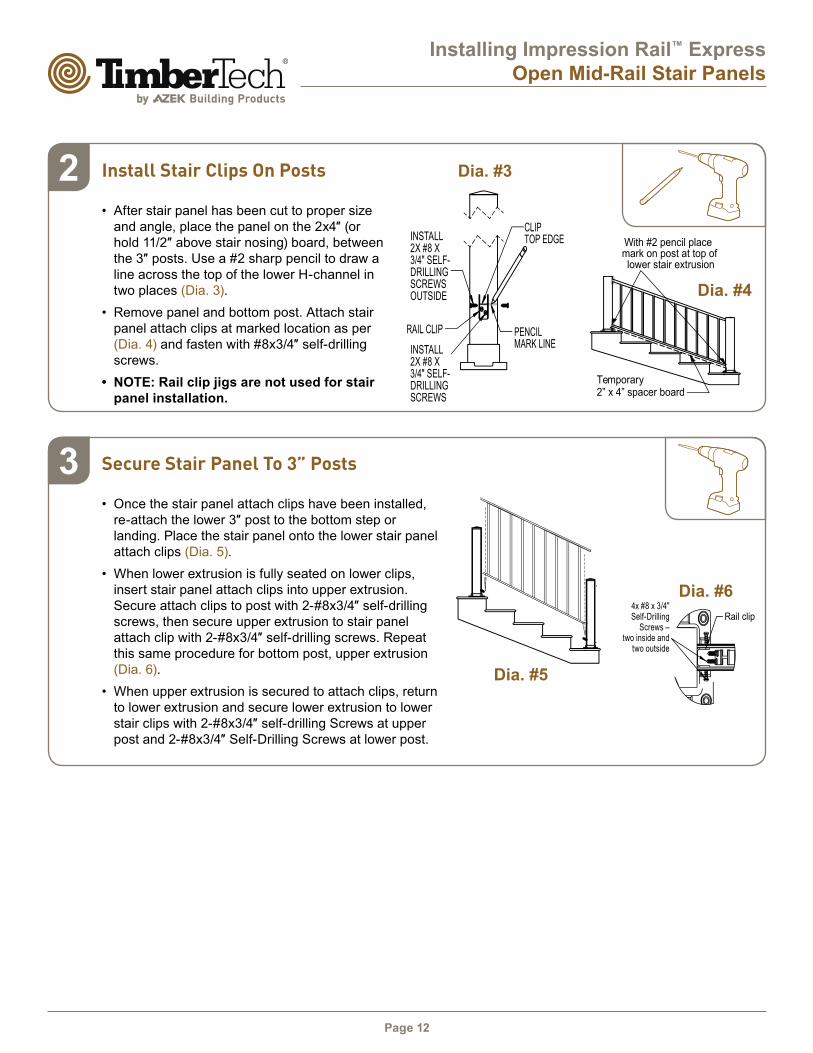
Dia. #32 Install Stair Clips On Posts
• After stair panel has been cut to proper size
and angle, place the panel on the 2x4″ (or hold 11/2″ above stair nosing) board, between the 3″ posts. Use a #2 sharp pencil to draw a line across the top of the lower H-channel in
two places (Dia. 3).
• Remove panel and bottom post. Attach stair
panel attach clips at marked location as per
(Dia. 4) and fasten with #8x3/4″ self-drilling screws.
• NOTE: Rail clip jigs are not used for stair
panel installation.
Temporary 2” x 4” spacer board
With #2 pencil place mark on post at top of lower stair extrusion
RAIL CLIP PENCILMARK LINE
CLIPTOP EDGEINSTALL
2X #8 X 3/4" SELF-DRILLING SCREWS OUTSIDE
INSTALL 2X #8 X 3/4" SELF-DRILLING SCREWS
Dia. #5
Dia. #6
3 Secure Stair Panel To 3” Posts
• Once the stair panel attach clips have been installed,
re-attach the lower 3″ post to the bottom step or landing. Place the stair panel onto the lower stair panel
attach clips (Dia. 5).
• When lower extrusion is fully seated on lower clips,
insert stair panel attach clips into upper extrusion.
Secure attach clips to post with 2-#8x3/4″ self-drilling screws, then secure upper extrusion to stair panel
attach clip with 2-#8x3/4″ self-drilling screws. Repeat this same procedure for bottom post, upper extrusion
(Dia. 6).
• When upper extrusion is secured to attach clips, return
to lower extrusion and secure lower extrusion to lower
stair clips with 2-#8x3/4″ self-drilling Screws at upper post and 2-#8x3/4″ Self-Drilling Screws at lower post.
Rail clip4x #8 x 3/4" Self-Drilling
Screws – two inside and
two outside
Page 13
Installing Impression Rail™ Express
Open Mid-Rail Stair Panels
Dia. #7
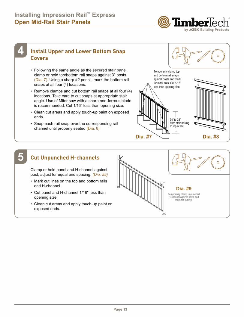
4 Install Upper and Lower Bottom Snap Covers
• Following the same angle as the secured stair panel,
clamp or hold top/bottom rail snaps against 3" posts
(Dia. 7). Using a sharp #2 pencil, mark the bottom rail
snaps at all four (4) locations.
• Remove clamps and cut bottom rail snaps at all four (4)
locations. Take care to cut snaps at appropriate stair
angle. Use of Miter saw with a sharp non-ferrous blade
is recommended. Cut 1/16" less than opening size.
• Clean cut areas and apply touch-up paint on exposed
ends.
• Snap each rail snap over the corresponding rail
channel until properly seated (Dia. 8).
34” to 38”from stair nosingto top of rail
Temporarily clamp top
and bottom rail snaps
against posts and mark
for miter cuts. Cut 1/16”
less than opening size.
Dia. #8
5 Cut Unpunched H-channels
Clamp or hold panel and H-channel against
post, adjust for equal end spacing. (Dia. #9)
• Mark cut lines on the top and bottom rails
and H-channel.
• Cut panel and H-channel 1/16″ less than opening size.
• Clean cut areas and apply touch-up paint on
exposed ends.
Dia. #9Temporarily clamp unpunched H-channel against posts and
mark for cutting.
Page 14
Installing Impression Rail™ Express
Open Mid-Rail Stair Panels
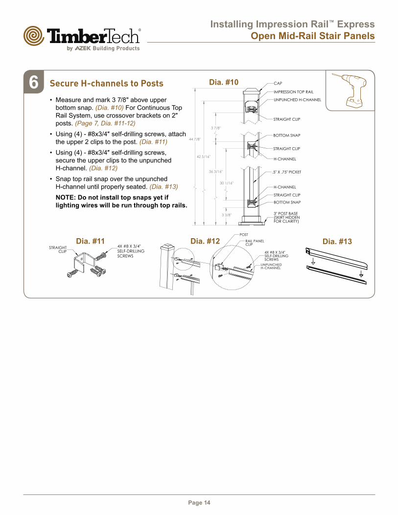
Dia. #13
Secure H-channels to Posts
• Measure and mark 3 7/8" above upper
bottom snap. (Dia. #10) For Continuous Top
Rail System, use crossover brackets on 2"
posts. (Page 7, Dia. #11-12)
• Using (4) - #8x3/4″ self-drilling screws, attach the upper 2 clips to the post. (Dia. #11)
• Using (4) - #8x3/4″ self-drilling screws, secure the upper clips to the unpunched
H-channel. (Dia. #12)
• Snap top rail snap over the unpunched
H-channel until properly seated. (Dia. #13)
NOTE: Do not install top snaps yet if
lighting wires will be run through top rails.
6
77.43 OUTSIDE OF SKIRTS
75.44 OUTSIDE OF POSTS 75.70 OUTSIDE OF CAPS
69.44 INSIDE OF POSTS
3.88 TYP
A
ASUPPORT LEG
SKIRT
3" END POSTS
30.06
3.36
44.78
36.20
3.88
42.33
SECTION A-A
CAP
IMPRESSION TOP RAIL
H-CHANNEL
STRAIGHT CLIP
BOTTOM SNAP
H-CHANNEL
STRAIGHT CLIP
3" POST BASE(SKIRT HIDDEN FOR CLARITY)
UNPUNCHED H-CHANNEL
STRAIGHT CLIP
BOTTOM SNAP
.5" X .75" PICKET
6X CLIP DETAIL
4X #8 X 3/4"TEK SCREWSTRAIGHT
CLIP
NOTES:1. ALL RAIL MUST BE ASSEMBLED AND FASTENED IN ACCORDANCE WITH ULTRALOX'S INSTALLATION INSTRUCTIONS.2. AVAILABLE COLORS ARE BLACK - WHITE - BRONZE.
REVISIONS - BALLOONS DENOTE CHANGES
REV. DESCRIPTION DATE APPROVED
A 7/31/2018 ZAG
A A
B B
4
4
3
3
2
2
1
1
SHOP DRAWING,IMPRESSION TOP RAIL,
3" END POSTS, 36" PICKETS, OPEN MIDRAIL,
6' SECTION
ADO NOT SCALE DRAWING SHEET 1 OF 1
7/31/18ZAG
UNLESS OTHERWISE SPECIFIED:
SCALE: 1:10 WEIGHT:
REVDWG. NO.
BSIZE
TITLE:
NAME DATE
MFG APPR.
ENG APPR.
CHECKED
DRAWN
FINISH
MATERIAL
INTERPRET GEOMETRICTOLERANCING PER: ASME Y14.5-2009
DIMENSIONS ARE IN INCHESTOLERANCES:SURFACE FINISH: 125 RMSANGULAR: .5 DEGLINEAR: .X .02 .XX .010 .XXX .005
PROPRIETARY AND CONFIDENTIALTHE INFORMATION CONTAINED IN THISDRAWING IS THE SOLE PROPERTY OFUltraLox. ANY REPRODUCTION IN PARTOR AS A WHOLE WITHOUT THE WRITTENPERMISSION OF UltraLox.
THIRD ANGLEPROJECTION:
A
Dia. #114X #8 X 3/4"
SELF-DRILLING
SCREWS
3" POST DETAIL
3" X 3"POST CAP
MOUNTINGSTRUCTURE
4X BASEMOUNTINGSCREWS
3" POSTBASE
RAIL PANEL CLIP DETAIL
RAIL PANEL
BOTTOM RAIL WALL MOUNT
2X WALL MOUNTING
SCREWS
IMPRESSION WALL MOUNT
WALL MOUNT DETAIL
2X WALL MOUNTINGSCREWS
MOUNTINGSTRUCTURE
BOTTOM RAIL WALL MOUNT
2X WALL MOUNTING
SCREWS
POST
H-CHANNEL
RAIL PANELCLIP
4X #8 X 3/4"TEK SCREWS
2" POST DETAIL
CROSSOVERBRACKET
4X BASEMOUNTINGSCREWS
MOUNTINGSTRUCTURE
2" POST
2" POSTBASE
2" BASESKIRT
SHEET 2 OF 2PROPRIETARY AND CONFIDENTIAL
THE INFORMATION CONTAINED IN THIS DRAWING IS THE SOLE PROPERTY OF UltraLox. ANY REPRODUCTION IN PART OR AS A WHOLE WITHOUT THE WRITTEN PERMISSION OF UltraLox IS NOT PERMITTED.
Dia. #12
UNPUNCHEDH-CHANNEL
4X #8 X 3/4"SELF-DRILLING SCREWS
77.43 OUTSIDE OF SKIRTS
75.44 OUTSIDE OF POSTS 75.70 OUTSIDE OF CAPS
69.44 INSIDE OF POSTS
3.88 TYP
A
ASUPPORT LEG
SKIRT
3" END POSTS
30.06
3.36
44.78
36.20
3.88
42.33
SECTION A-A
CAP
IMPRESSION TOP RAIL
H-CHANNEL
STRAIGHT CLIP
BOTTOM SNAP
H-CHANNEL
STRAIGHT CLIP
3" POST BASE(SKIRT HIDDEN FOR CLARITY)
UNPUNCHED H-CHANNEL
STRAIGHT CLIP
BOTTOM SNAP
.5" X .75" PICKET
6X CLIP DETAIL
4X #8 X 3/4"TEK SCREWSTRAIGHT
CLIP
NOTES:1. ALL RAIL MUST BE ASSEMBLED AND FASTENED IN ACCORDANCE WITH ULTRALOX'S INSTALLATION INSTRUCTIONS.2. AVAILABLE COLORS ARE BLACK - WHITE - BRONZE.
REVISIONS - BALLOONS DENOTE CHANGES
REV. DESCRIPTION DATE APPROVED
A 7/31/2018 ZAG
A A
B B
4
4
3
3
2
2
1
1
SHOP DRAWING,IMPRESSION TOP RAIL,
3" END POSTS, 36" PICKETS, OPEN MIDRAIL,
6' SECTION
ADO NOT SCALE DRAWING SHEET 1 OF 1
7/31/18ZAG
UNLESS OTHERWISE SPECIFIED:
SCALE: 1:10 WEIGHT:
REVDWG. NO.
BSIZE
TITLE:
NAME DATE
MFG APPR.
ENG APPR.
CHECKED
DRAWN
FINISH
MATERIAL
INTERPRET GEOMETRICTOLERANCING PER: ASME Y14.5-2009
DIMENSIONS ARE IN INCHESTOLERANCES:SURFACE FINISH: 125 RMSANGULAR: .5 DEGLINEAR: .X .02 .XX .010 .XXX .005
PROPRIETARY AND CONFIDENTIALTHE INFORMATION CONTAINED IN THISDRAWING IS THE SOLE PROPERTY OFUltraLox. ANY REPRODUCTION IN PARTOR AS A WHOLE WITHOUT THE WRITTENPERMISSION OF UltraLox.
THIRD ANGLEPROJECTION:
A
Dia. #10
44 7/8"
42 5/16"
36 3/16"
30 1/16"
3 3/8"
3 7/8"
Page 15
Installing Impression Rail™ Express
Open Mid-Rail Aluminum Railing System
Important Note:
The diagrams and instructions in this brochure are for illustration purposes only and are not meant to replace a licensed
professional. Any construction or use of the product must be in accordance with all local zoning and/or building codes. The
consumer assumes all risks and liability associated with the construction or use of this product. The consumer or contractor
should take all necessary steps to ensure the safety of everyone involved in the project, including, but not limited to, wearing the
appropriate safety equipment. Except as contained in the written limited warranty, AZEK does not provide any other warranty,
either express or implied, and shall not be liable for any damages, including consequential damages.
Plan Drawings / Notes

TimberTech.com
AZEK Building Products
1330 W Fulton Market, Suite #350
Chicago, IL 60607©2019 AZEK Building Products. All Rights Reserved.