Embed Size (px)
Citation preview
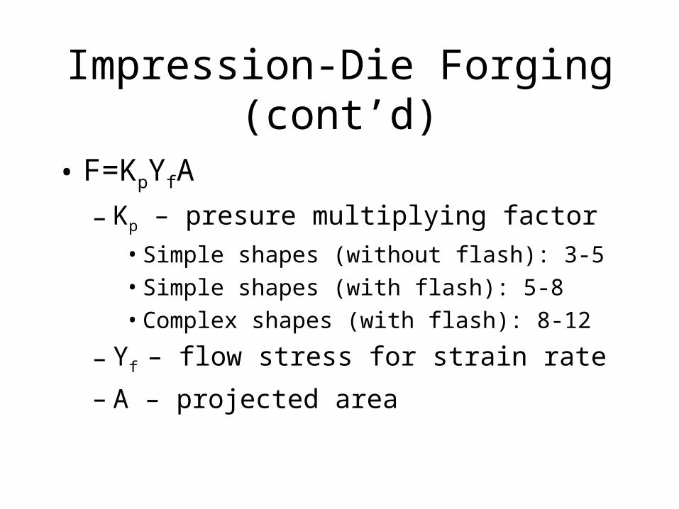
Impression-Die Forging (cont’d)
• F=KpYfA
– Kp – presure multiplying factor• Simple shapes (without flash): 3-5
• Simple shapes (with flash): 5-8
• Complex shapes (with flash): 8-12
– Yf – flow stress for strain rate
– A – projected area
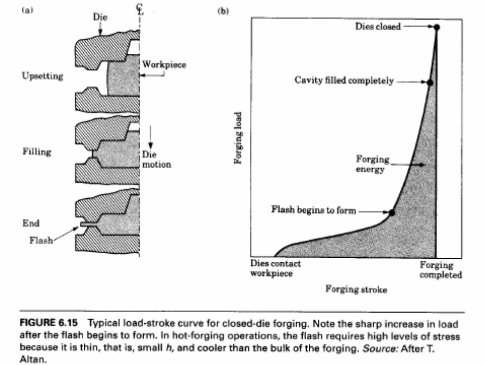
• Force increases gradually at first
• Force increases rapidly when flash forms
• Final steep force is applied to achieve complete filling

• http://www.mscsoftware.com.au/products/software/msc/superforge/
Closed Die Forging
• Forging created without flash
• Proper volume of die is required
• Precise control of parameters
• Near net shape forging
• Very precise machines
• Special die designs
• Aluminum, magnesium, etc.
Isothermal Forging
• (Hot die forging)
• Die heated to temperature of forging
• Good dimensional accuracy
• Die is made of nickel alloy
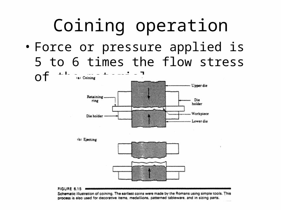
Coining operation• Force or pressure applied is 5 to 6 times the
flow stress of the material
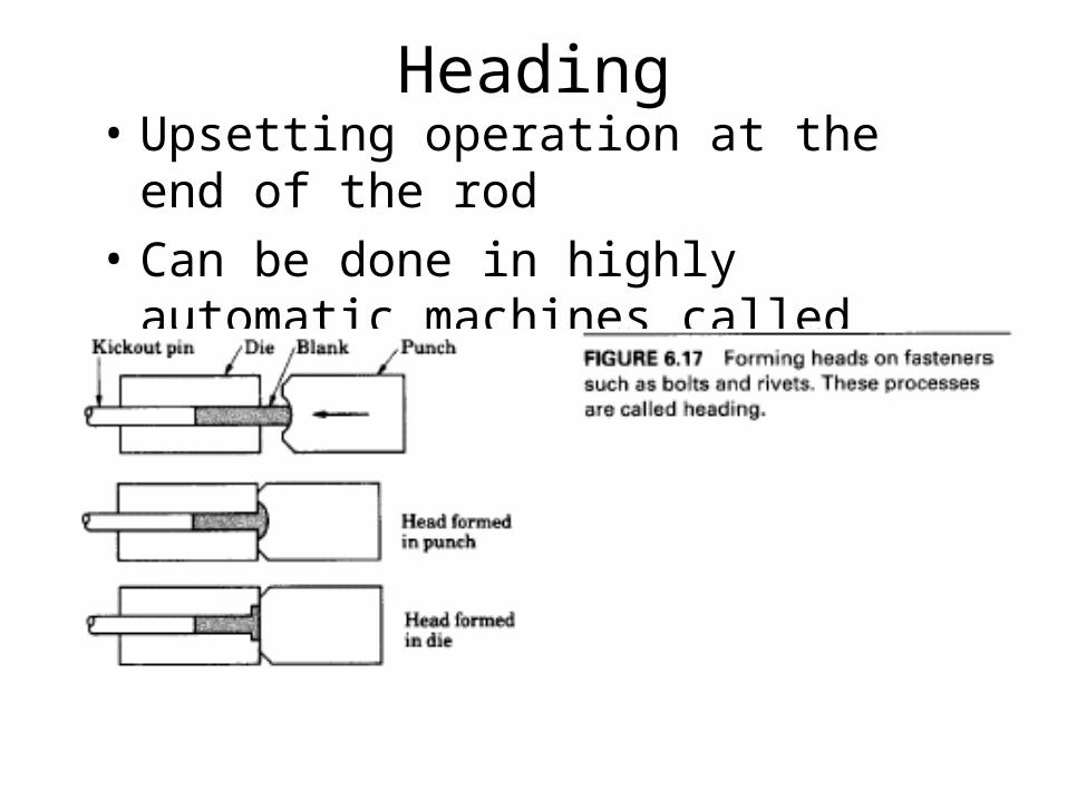
Heading• Upsetting operation at the end of the rod
• Can be done in highly automatic machines called Headers.
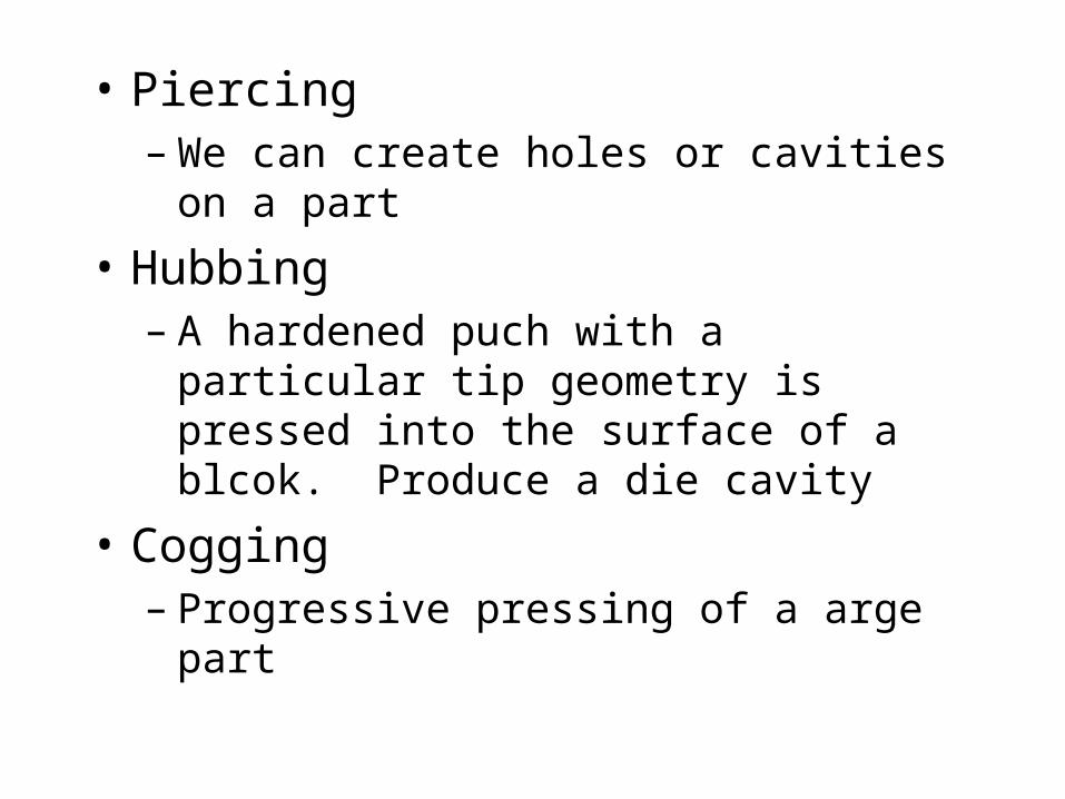
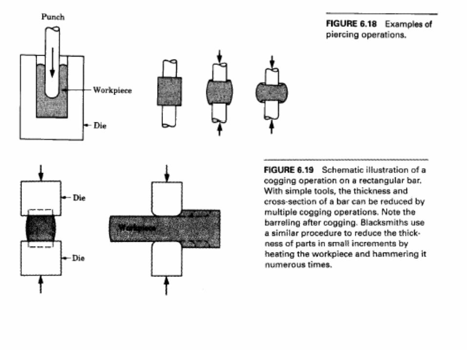
• Piercing– We can create holes or cavities on a part
• Hubbing– A hardened puch with a particular tip geometry
is pressed into the surface of a blcok. Produce a die cavity
• Cogging– Progressive pressing of a arge part

Die Allowances
• Shrinkage allowances
• Machining allowances
• Work holding allowance
• Material Used– Tool Steel, Die steel– High carbon alloy steel (Cr, Ni, vanadium)– Hardness: Rc=45-60
• Material should have strength, toughness, at high temp.
• Hardenability, mechanical and thermal shock resistance, wear resistance
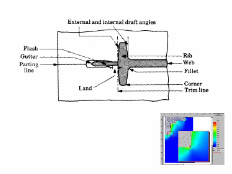
• Dies are the most critical part of the forging operation– Proper fillet radius should be provided– Draft angle for all vertical faces for ease of
removal – Flash should be allowed to form – Flash = 3% of max. thickness
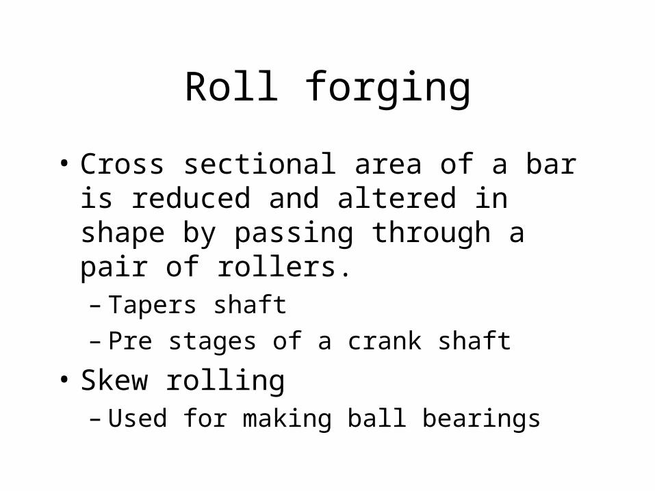
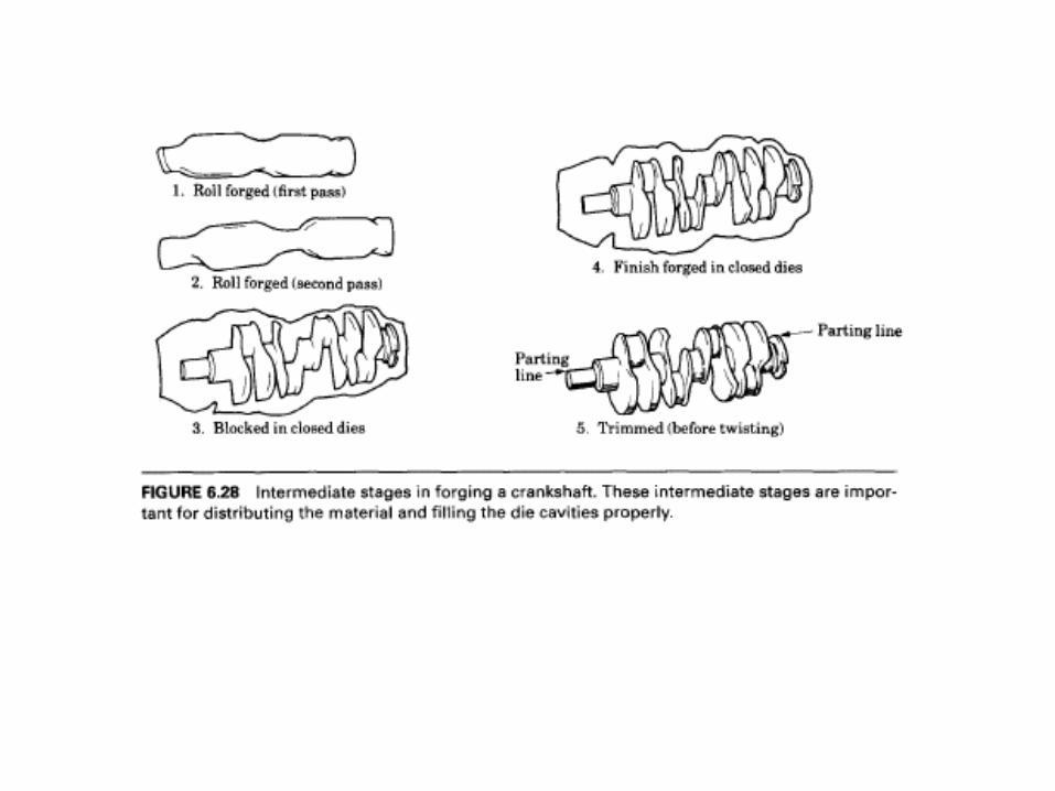
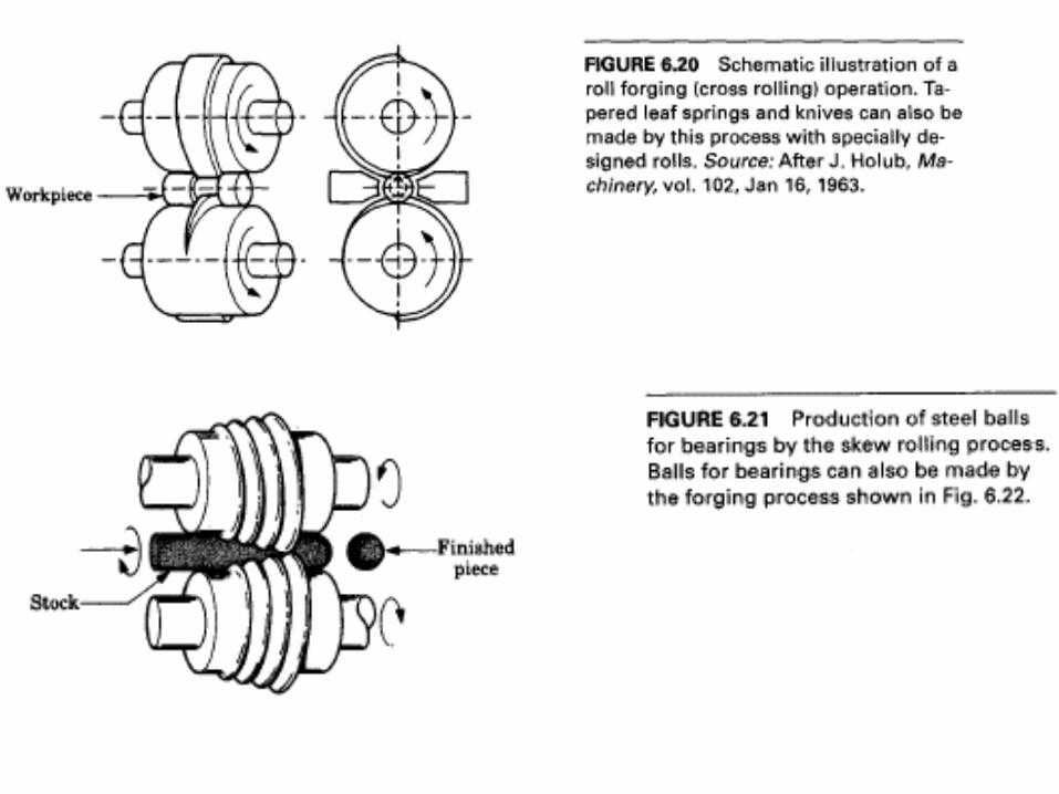
Roll forging
• Cross sectional area of a bar is reduced and altered in shape by passing through a pair of rollers.– Tapers shaft– Pre stages of a crank shaft
• Skew rolling– Used for making ball bearings
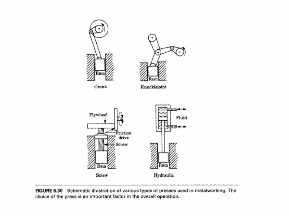
Type of Forging Process
• Hydraulic press:– Constant low speed– Ram speed can be varied– Large amount of energy can be applied (75,000
tons)
• Mechanical Press– Usually uses crank or eccentric– Force depends on the stroke position– Proper setting of the position is important– 12,000 tons
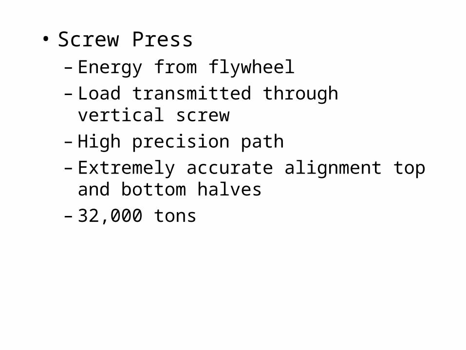
• Screw Press– Energy from flywheel– Load transmitted through vertical screw– High precision path– Extremely accurate alignment top and bottom
halves– 32,000 tons
• Hammers– Potential energy of the ram– Speed can be high– Sometimes steam or air is used to aid the die– Multiple blows may be needed
• Selection of Press depends on– Precision– Strain rate sensitivity– Amount of deformation– Size of forging– Production rate
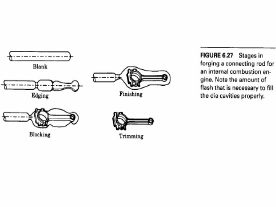
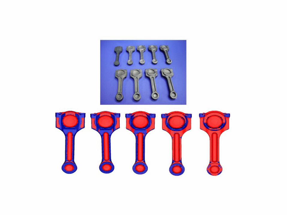
• Metal flows in the direction of least resistance
• Distribute material so that it can properly fill die cavity
• Several “Intermediate stage” Dies are used for obtaining final forging– E.G. connecting rod, crankshaft
Defects in Forging
• Fatigue resistance is reduced
• Corrosion, stress raisers
• In complete metal for machining
• Mismatch of halves of the pierce
• Poor strength in the direction of principle stresses
Anisotropic Behavior
• Not always considered as a defect
• Metal flows in different directions
• Thus we obtain different strength at different points of a forging
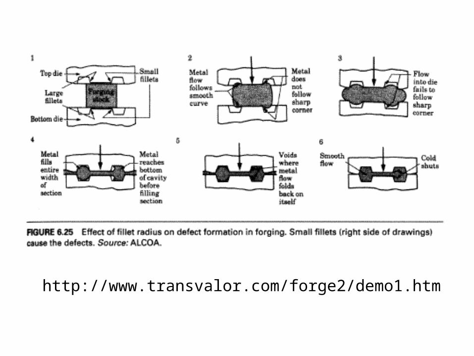
Effect of corner radii
• Metal flows better as a larger radius than in a smaller radius
• For smaller radius, the metal can fold over itself to cause “cold shuts”
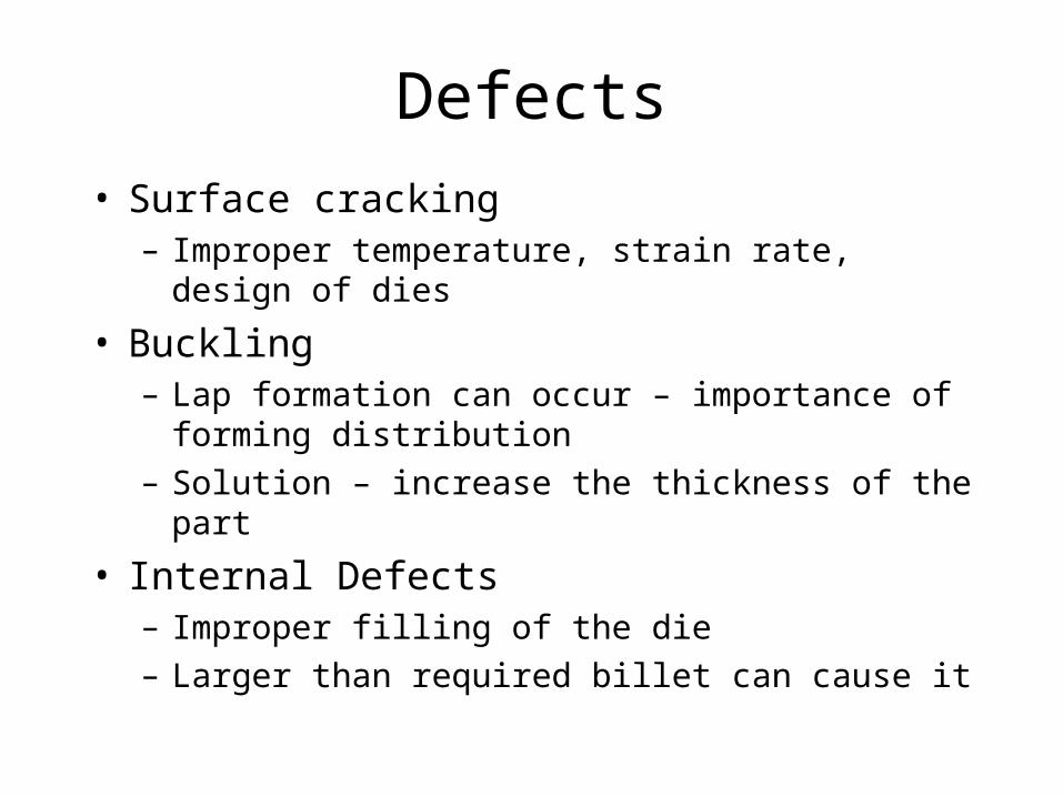
Defects
• Surface cracking– Improper temperature, strain rate, design of dies
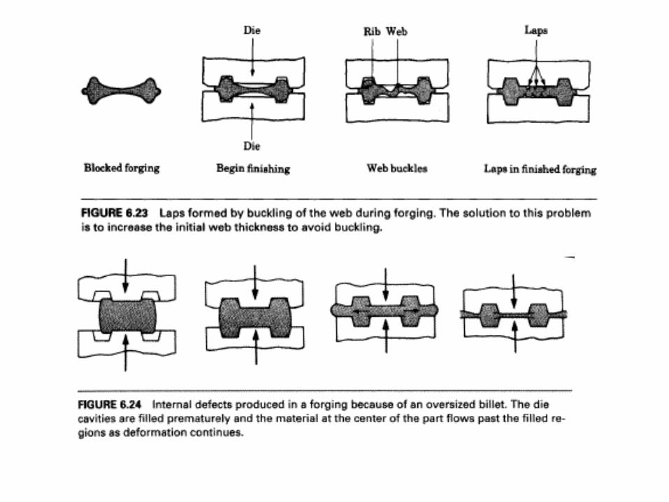
• Buckling– Lap formation can occur – importance of forming
distribution
– Solution – increase the thickness of the part
• Internal Defects– Improper filling of the die
– Larger than required billet can cause it
http://www.transvalor.com/forge2/demo1.htm
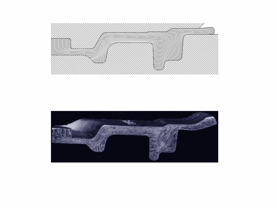
Grain Flow Pattern
• Grains flow is exposed: end grains
• Can be avoided by intermediate steps in forging and proper orientation of workpieces– Stress raiser– Corrosion, etc.
Summary• True Strain/True Stress, Strain rate, strain rate sensitivity• Forging – Forces involved in rectangular and cylindrical
work pieces• Different types of forging – open, closed, impression etc
– Multi stage forging
• Cogging, coining etc• Roll forging• Types of presses• Defects


![Presure-Volume-Temperature Properties of H2O-CO2 Fluids (Geophysics) [Short Article] - T. Bowers (1995) WW](https://img.pdfslide.us/doc/110x75/55cf922c550346f57b944a85/presure-volume-temperature-properties-of-h2o-co2-fluids-geophysics-short.jpg)