Embed Size (px)
Citation preview

1
Importer User’s Guide
Software Rev. 3.0.5 June 5, 2008
Copyright © Harris Corporation. All rights reserved. The contents of this publication may not be reproduced in any media without the express written permission of Harris Corporation.
The iBiquity Digital logo, “iBiquity Digital”, "iBiquity", the HD Radio logo and the HD logo are registered trademarks of iBiquity Digital Corporation.
Harris Corporation Broadcast Communications Division 4393 Digital Way Mason, OH 45040 Service: (217) 222-8200

2
TABLE OF CONTENTS 1 AAS Overview ......................................................................................................................... 3
1.1 Importer Component Overview ..................................................................................... 4 2 Basic Operating Procedures ..................................................................................................... 5
2.1 Importer Control Panel ................................................................................................... 5 2.2 Capture Client ................................................................................................................ 8
2.2.1 Operation ................................................................................................................... 8 2.2.2 Configuration ............................................................................................................. 9 2.2.3 PAD Data ................................................................................................................. 10
2.3 Streaming Client .......................................................................................................... 12 2.3.1 Operating Procedures ............................................................................................... 12 2.3.2 Configuration ........................................................................................................... 13 2.3.3 Playlist setup ............................................................................................................ 13 2.3.4 Setting up PSD data associated with audio .............................................................. 15 2.3.5 Running the Streaming Client ................................................................................. 15
2.4 Data Client ................................................................................................................... 16 2.4.1 Operation ................................................................................................................. 16 2.4.2 Configuration ........................................................................................................... 17 2.4.3 Generic Data Format................................................................................................ 18
2.5 WebAdmin ................................................................................................................... 19 2.5.1 Operation ................................................................................................................. 19
2.6 Guidelines for Changing Configurations ..................................................................... 30 3 Advanced Operations ............................................................................................................. 31
3.1 Starting and Running the Importer Components Individually ..................................... 31 3.1.1 Administrator ........................................................................................................... 31 3.1.2 Logistics Processor .................................................................................................. 33 3.1.3 Connection Manager ................................................................................................ 34
3.2 Importer Configuration ................................................................................................ 36 3.2.1 Logging Configuration ............................................................................................ 36 3.2.2 Configuration from the Control Panel ..................................................................... 37
3.3 Database Management ................................................................................................. 39 3.3.1 Backup the Database: .............................................................................................. 40 3.3.2 Restore the Database: .............................................................................................. 41 3.3.3 Save the Database .................................................................................................... 42 3.3.4 Merge the Database ................................................................................................. 43
3
1 AAS Overview
With the advent of HD Radio, broadcast stations can now transmit their programs as a high quality digital signal. In addition to the Main Program Service (MPS) and Station Information Service (SIS), the HD Radio system also provides the capacity to transmit other digital services referred to as Advanced Application Services (AAS). Examples of AAS include multicast programming, electronic program guides, navigation maps, traffic information, multimedia programming and other content.
To meet the demands for AAS, the AAS framework has been created. The AAS framework provides a common infrastructure to support the radio station in managing its services and bandwidth.
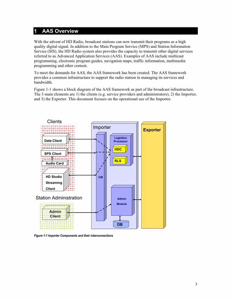
Figure 1-1 shows a block diagram of the AAS framework as part of the broadcast infrastructure. The 3 main elements are 1) the clients (e.g. service providers and administrators), 2) the Importer, and 3) the Exporter. This document focuses on the operational use of the Importer.
CM
Logistics Processor
Admin
Module
ExporterImporterClients
SPS Client
Audio Card
Data Client
HD Studio
Streaming
Client
Admin Client
DB
Station Administration
HDC
RLS
Figure 1-1 Importer Components and their interconnections
4
1.1 Importer Component Overview
The following paragraphs provide a brief description of the various Importer Components.
• Importer Database: The persistent data for the functioning of the Importer is stored in the Importer database. All the Administrative functionality is handled by interaction with this database. Importer components like the Connection Manager and the Logistics Processor write data about their functioning into the Importer Database.
• Administration (Admin Module): Administration is basically an offline activity to enable broadcast stations to configure the Importer according to their requirements. The Admin Module also communicates with the Exciter or Exporter to configure these sub-systems into the appropriate operational modes based on the desired service mode and bandwidth allocations. Finally, the Admin Module handles all the registration of service providers, services, and Importer configurations.
• Logistics Processor: The Logistics Processor is responsible for the data reception from the service providers in accordance with the specific protocol chosen for that particular service. For example, if the service is a multicast audio service, the Logistics Processor is responsible for the HDC encoding of the audio program. For data services, including PSD, the Logistics Processor is responsible for encoding the data using the Radio Link Subsystem (RLS). In addition to encoding data using the proper transmission protocol, the Logistics Processor is also responsible for managing the bandwidth and QoS for each service as defined in the configurations between the service provider and the broadcast station. It communicates with the Connection Manager as well as an Exciter or Exporter. It also communicates with the Importer Database in order to retrieve configuration information and save its performance data.
• Connection Manager (CM): The Connection Manager is responsible for managing the connections from the various services. It authenticates service providers and delivers the specific information regarding the configurations and services for each service provider. It provides the mechanism for service providers to deliver data services to the Importer. It allows multiple service providers to connect to the Importer and multiple services to be delivered by each service provider. The Connection Manager connects to the Importer Database for authentication information as well as to the Logistics Processor for bandwidth and QoS information.
• Logging Service: Although not shown in Figure 1-1, the Importer incorporates a logging package that allows the various components to write messages to a file. These messages can be informational (i.e. documenting certain events) or can indicate errors or warnings. This file can be very useful for failure analysis in case the Importer should cease to function properly. This logging package is implemented as a Windows “Service” and hence will start automatically on system start-up.
• Control Panel: Although not shown in Figure 1-1, the Importer software includes a module that can be used to control, configure, and monitor the main Importer components.

5
2 Basic Operating Procedures
2.1 Importer Control Panel
While each of the Importer components can be started individually, the recommended method to start, configure, and monitor the Importer is through the Control Panel. The Control Panel allows the hiding of the various Importer component windows, reducing the amount of clutter on the desktop. The Control Panel can also be used to set the Importer configuration information, eliminating the need to directly edit the XML configuration files. Finally, the Control Panel can be used to view and manipulate the log files created by the Importer components.
The Control Panel can be started by:
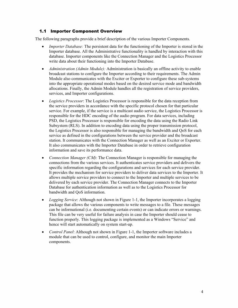
Double-clicking desktop icon: or The executable file found at: C:\Program\Files\iBiquity\Digital\Importer\Servers\ControlPanel.exe or From the start menu select: Start Menu -> iBiquity Digital -> Importer -> ControlPanel Once the application is started a Window similar to Figure 2-1 will be displayed.
6
Figure 2-1 - Control Panel Main Window.
To start the Importer press the start Importer Icon or Importer->Start. To stop the Importer press the Stop Icon or Importer->Stop.
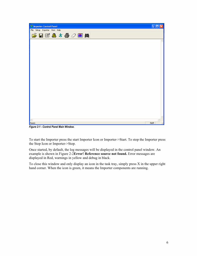
Once started, by default, the log messages will be displayed in the control panel window. An example is shown in Figure 2-2Error! Reference source not found. Error messages are displayed in Red, warnings in yellow and debug in black.
To close this window and only display an icon in the task tray, simply press X in the upper right hand corner. When the icon is green, it means the Importer components are running.
7
Figure 2-2 - Control Panel with Log messages displayed.
To erase the contents of this window press the Eraser icon.
To save the contents of the window to a file press the file save icon.
To view a previously stored log file, press the file open icon. Note: This can only be done when the Importer is not running.
To enable or disable log messages, use the display icon.
To search for specific strings within a log file use the spyglass icon.
2.1.1 Importer & Log Service Setup
See Section 3.2.2 for explanation of the Control Panel configuration and Log Service configuration.
8
2.2 Capture Client
The Capture Client captures audio from the audio card and feeds it to the Importer.
In addition, this client accepts PSD messages in ID3 or HDP format at the specified port ( by default 10100 for SPS1 and 10011 for SPS2) and uses the Importer API to send this data along with the SPS audio samples.
2.2.1 Operation
To start the Capture Client, double click the on the default desktop.
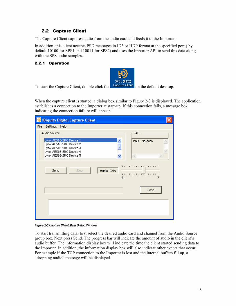
When the capture client is started, a dialog box similar to Figure 2-3 is displayed. The application establishes a connection to the Importer at start-up. If this connection fails, a message box indicating the connection failure will appear.
Figure 2-3 Capture Client Main Dialog Window
To start transmitting data, first select the desired audio card and channel from the Audio Source group box. Next press Send. The progress bar will indicate the amount of audio in the client’s audio buffer. The information display box will indicate the time the client started sending data to the Importer. In addition, the information display box will also indicate other events that occur. For example if the TCP connection to the Importer is lost and the internal buffers fill up, a “dropping audio” message will be displayed.
9
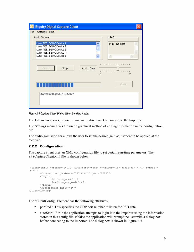
Figure 2-4 Capture Client Dialog When Sending Audio.
The File menu allows the user to manually disconnect or connect to the Importer.
The Settings menu gives the user a graphical method of editing information in the configuration file.
The audio gain slide bar allows the user to set the desired gain adjustment to be applied at the receiver.
2.2.2 Configuration
The capture client uses an XML configuration file to set certain run-time parameters. The SPSCaptureClient.xml file is shown below:
<ClientConfig portPAD="10010" autoStart="true" extraBuf="15" audioGain = “1” format = “HDP”> <Connection ipAddress="127.0.0.1" port="1010"/> <Login> <uid>sps_one</uid> <pwd>sps_one_pwd</pwd> </Login> <AudioSource index="4"/> </ClientConfig>
The “ClientConfig” Element has the following attributes:
portPAD: This specifies the UDP port number to listen for PSD data.
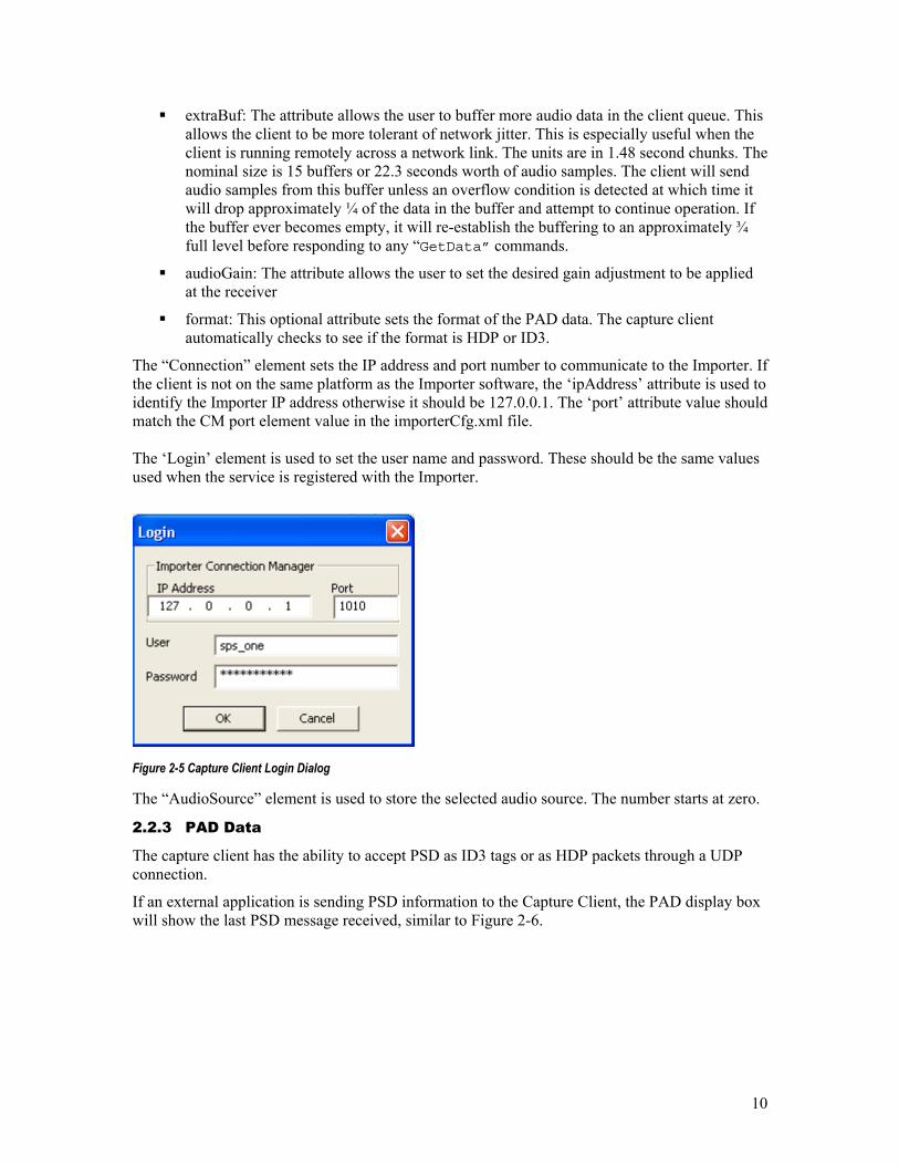
autoStart: If true the application attempts to login into the Importer using the information stored in this config file. If false the application will prompt the user with a dialog box before connecting to the Importer. The dialog box is shown in Figure 2-5.
10
extraBuf: The attribute allows the user to buffer more audio data in the client queue. This allows the client to be more tolerant of network jitter. This is especially useful when the client is running remotely across a network link. The units are in 1.48 second chunks. The nominal size is 15 buffers or 22.3 seconds worth of audio samples. The client will send audio samples from this buffer unless an overflow condition is detected at which time it will drop approximately ¼ of the data in the buffer and attempt to continue operation. If the buffer ever becomes empty, it will re-establish the buffering to an approximately ¾ full level before responding to any “GetData” commands.
audioGain: The attribute allows the user to set the desired gain adjustment to be applied at the receiver
format: This optional attribute sets the format of the PAD data. The capture client automatically checks to see if the format is HDP or ID3.
The “Connection” element sets the IP address and port number to communicate to the Importer. If the client is not on the same platform as the Importer software, the ‘ipAddress’ attribute is used to identify the Importer IP address otherwise it should be 127.0.0.1. The ‘port’ attribute value should match the CM port element value in the importerCfg.xml file. The ‘Login’ element is used to set the user name and password. These should be the same values used when the service is registered with the Importer.
Figure 2-5 Capture Client Login Dialog
The “AudioSource” element is used to store the selected audio source. The number starts at zero.
2.2.3 PAD Data
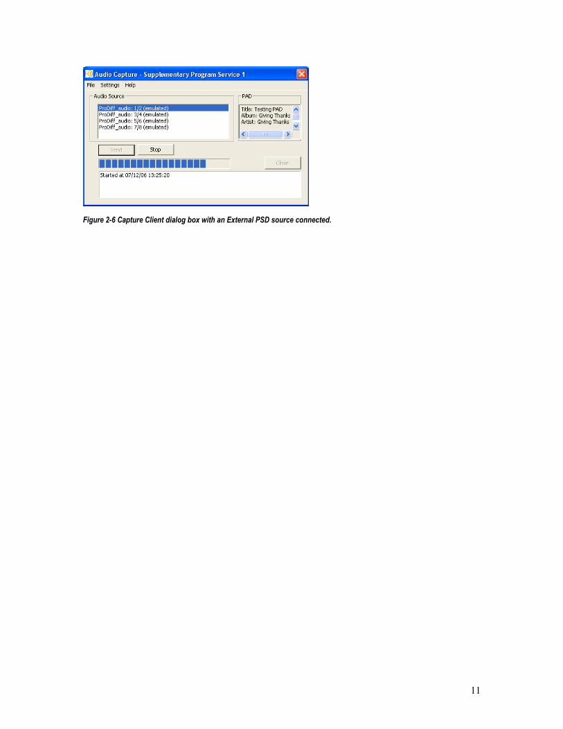
The capture client has the ability to accept PSD as ID3 tags or as HDP packets through a UDP connection.
If an external application is sending PSD information to the Capture Client, the PAD display box will show the last PSD message received, similar to Figure 2-6.
11
Figure 2-6 Capture Client dialog box with an External PSD source connected.
12
2.3 Streaming Client
The SPS Streaming Client is an application that is intended to facilitate the testing of SPS and Data applications without having a complete studio automation system. The Streaming Client can be used to create play lists with PSD. The SPS Streaming Client is used as SPS audio sources. It connects directly to an Importer, eliminating the need for an audio card dedicated to the SPS service. This manual describes how to install and use the SPS Streaming Client.
2.3.1 Operating Procedures
To start the SPS Streaming Client use one of the following methods; which may or may not be available depending on how the client was installed
Double click the Icon on the default desktop
From the Start menu select Start->Programs->iBiquity Digital->Importer->ImporterTools->StreamingClient
Double-clicking the executable file found at C:\Program Files\iBiquity Digital\Importer\Clients\SPSStreamingClient.exe
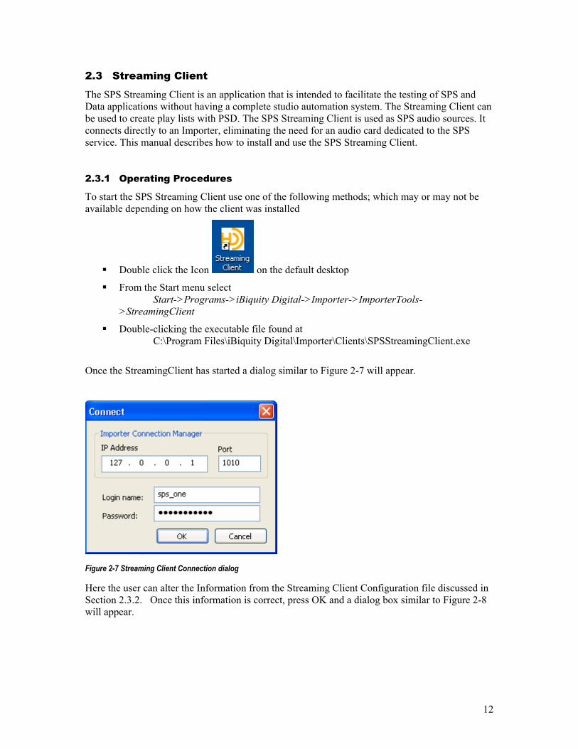
Once the StreamingClient has started a dialog similar to Figure 2-7 will appear.
Figure 2-7 Streaming Client Connection dialog
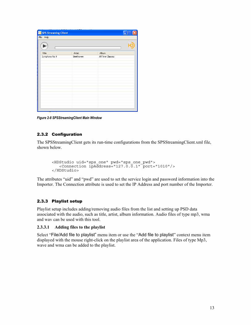
Here the user can alter the Information from the Streaming Client Configuration file discussed in Section 2.3.2. Once this information is correct, press OK and a dialog box similar to Figure 2-8 will appear.
13
Figure 2-8 SPSStreamingClient Main Window
2.3.2 Configuration
The SPSStreamingClient gets its run-time configurations from the SPSStreamingClient.xml file, shown below.
<HDStudio uid="sps_one" pwd="sps_one_pwd"> <Connection ipAddress="127.0.0.1" port="1010"/> </HDStudio>
The attributes “uid” and “pwd” are used to set the service login and password information into the Importer. The Connection attribute is used to set the IP Address and port number of the Importer.
2.3.3 Playlist setup
Playlist setup includes adding/removing audio files from the list and setting up PSD data associated with the audio, such as title, artist, album information. Audio files of type mp3, wma and wav can be used with this tool.
2.3.3.1 Adding files to the playlist
Select “File/Add file to playlist” menu item or use the “Add file to playlist” context menu item displayed with the mouse right-click on the playlist area of the application. Files of type Mp3, wave and wma can be added to the playlist.

14
Figure 2-9 Adding Files to the Playlist
A Windows “Open” file dialog will be displayed. Navigate to the audio source folder containing your audio file, select the audio file and click Open. The file should appear in the playlist area of the application.
2.3.3.2 Removing files from the playlist
Select the item to be removed in the playlist area of the application. Select “File/Delete file from playlist” menu item or use the “Delete file from playlist” context menu item displayed with the mouse right-click on the selected item.
Figure 2-10 Removing Files From the Playlist
The item should disappear from the playlist displayed by the application.
15
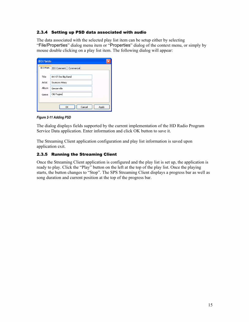
2.3.4 Setting up PSD data associated with audio
The data associated with the selected play list item can be setup either by selecting “File/Properties” dialog menu item or “Properties” dialog of the context menu, or simply by mouse double clicking on a play list item. The following dialog will appear:
Figure 2-11 Adding PSD
The dialog displays fields supported by the current implementation of the HD Radio Program Service Data application. Enter information and click OK button to save it. The Streaming Client application configuration and play list information is saved upon application exit.
2.3.5 Running the Streaming Client
Once the Streaming Client application is configured and the play list is set up, the application is ready to play. Click the “Play” button on the left at the top of the play list. Once the playing starts, the button changes to “Stop”. The SPS Streaming Client displays a progress bar as well as song duration and current position at the top of the progress bar.
16
2.4 Data Client
The Data Client application is a generic implementation of the Importer Services API for discrete object data applications. It can be used to transmit any type of discrete data packets as long as the data is formatted in the generic data client format, described in Section 2.4.3. The tool allows quick prototyping of data applications by relieving the developers from having to write their own data clients. It also provides data application developers with an example implementation of the Importer API. The client can be used for both packet-based or streaming data applications.
2.4.1 Operation
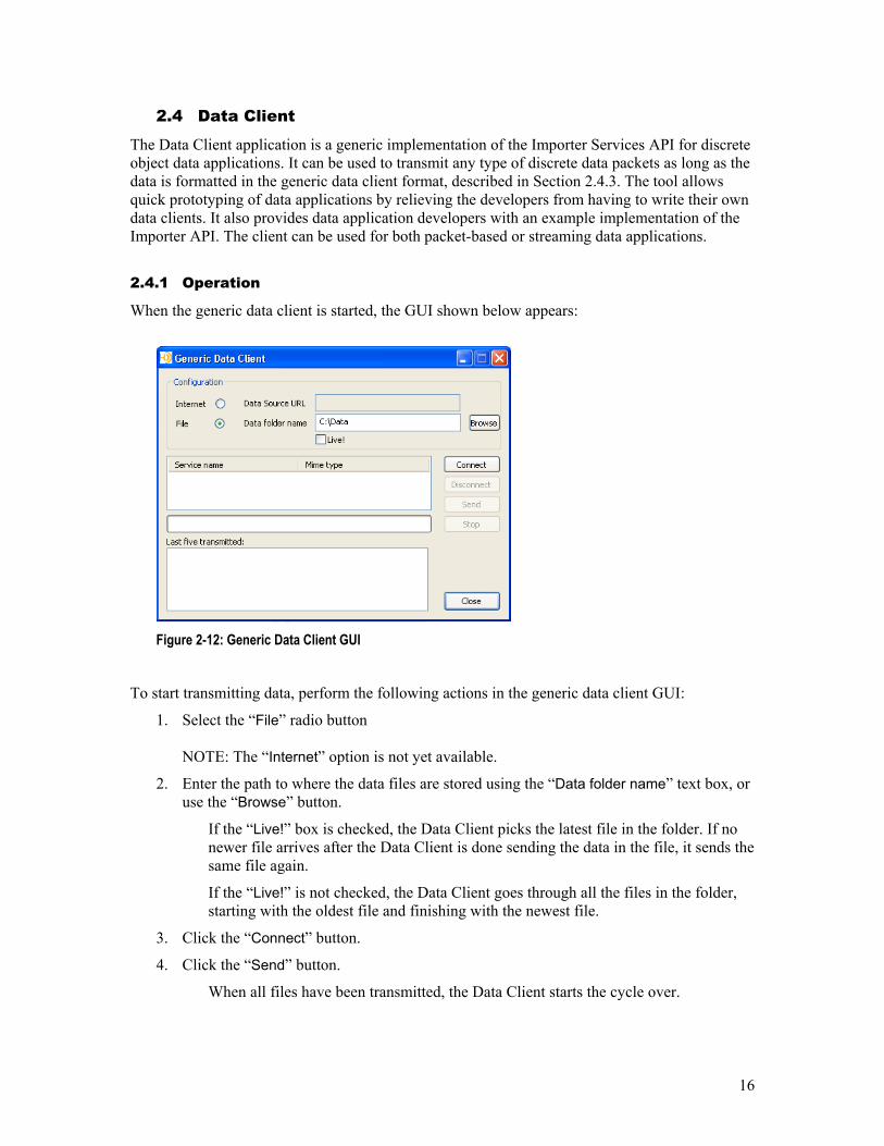
When the generic data client is started, the GUI shown below appears:
Figure 2-12: Generic Data Client GUI
To start transmitting data, perform the following actions in the generic data client GUI:
1. Select the “File” radio button NOTE: The “Internet” option is not yet available.
2. Enter the path to where the data files are stored using the “Data folder name” text box, or use the “Browse” button.
If the “Live!” box is checked, the Data Client picks the latest file in the folder. If no newer file arrives after the Data Client is done sending the data in the file, it sends the same file again.
If the “Live!” is not checked, the Data Client goes through all the files in the folder, starting with the oldest file and finishing with the newest file.
3. Click the “Connect” button.
4. Click the “Send” button.
When all files have been transmitted, the Data Client starts the cycle over.
17
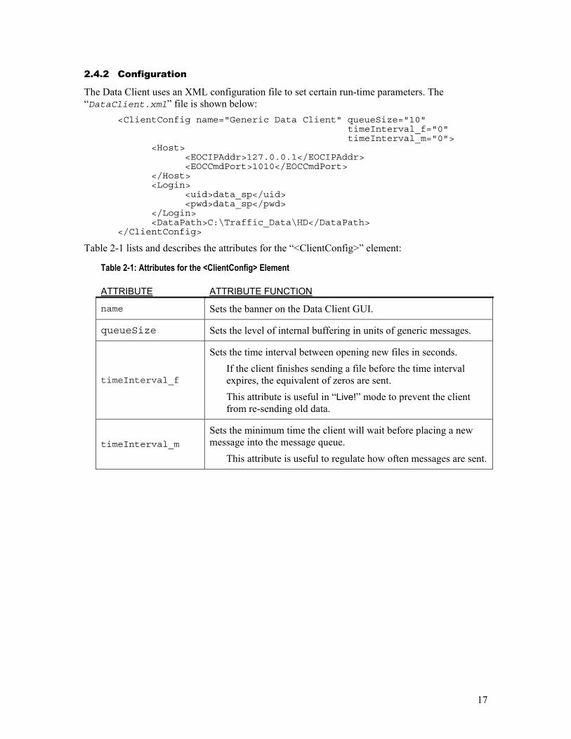
2.4.2 Configuration
The Data Client uses an XML configuration file to set certain run-time parameters. The “DataClient.xml” file is shown below:
<ClientConfig name="Generic Data Client" queueSize="10" timeInterval_f="0" timeInterval_m="0">
<Host> <EOCIPAddr>127.0.0.1</EOCIPAddr> <EOCCmdPort>1010</EOCCmdPort>
</Host> <Login>
<uid>data_sp</uid> <pwd>data_sp</pwd>
</Login> <DataPath>C:\Traffic_Data\HD</DataPath>
</ClientConfig>
Table 2-1 lists and describes the attributes for the “<ClientConfig>” element:
Table 2-1: Attributes for the <ClientConfig> Element
ATTRIBUTE ATTRIBUTE FUNCTION
name Sets the banner on the Data Client GUI.
queueSize Sets the level of internal buffering in units of generic messages.
timeInterval_f
Sets the time interval between opening new files in seconds. If the client finishes sending a file before the time interval expires, the equivalent of zeros are sent. This attribute is useful in “Live!” mode to prevent the client from re-sending old data.
timeInterval_m
Sets the minimum time the client will wait before placing a new message into the message queue.
This attribute is useful to regulate how often messages are sent.

18
The “<Host>” element sets the IP address and port number to communicate to the Importer.
If the client is not on the same platform as the Importer software, the “<EOCIPAddr>” element is used to identify the Importer IP address. Otherwise it should be 127.0.0.1.
The “<EOCCmdPort>” element value should match the CM port element value in the “importerCfg.xml” file.
The “<Login>” element is used to set the user name and password.
These should be the same values used when the service is registered with the Importer. The “<DataPath>” element is used to set/store the default path to the generic data files.
2.4.3 Generic Data Format
A generic data file consists of a series of generic messages. A generic message consists of a message header and a message body. The message header is four bytes long and has the following structure:
First 2 bytes – sync byte sequence: 1st byte = 0xFA, 2nd byte = 0xFB
Next 2 bytes – data length in bytes (should not be more that 8192 bytes) in little-endian format.
The message body starts at the fifth byte and contains actual data to be transmitted.
When the client reads the data, it performs synchronization by reading the message header and verifying that the message body is either:
Followed by the next message header with its own sync byte sequence,
or
Confirmed that it is the last message in a file which is verified by the “end of file” check.
19
2.5 WebAdmin
Advanced Services such as secondary audio programs and data services that are sent through the Importer are provided by service providers. In order for service providers to connect to the Importer and send their services, service providers must be registered with the Importer. A service provider then defines its service(s) and creates Importer configurations to allow that service to be broadcast.
All of these administrative actions (i.e. service provider registration, service definition, and Importer configuration management) are managed using the Administration portion of the Importer.
2.5.1 Operation
To start the WebAdmin application, double click the WebAdmin icon: on the default desktop
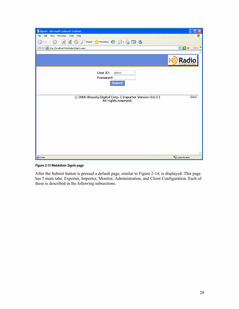
When the WebAdmin application is started the Sign In page will be similar to the one shown in Figure 2-13.
The default User ID is “admin”, and the default Password is also “admin”.
20
Figure 2-13 WebAdmin SignIn page
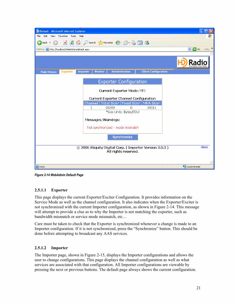
After the Submit button is pressed a default page, similar to Figure 2-14, is displayed. This page has 5 main tabs: Exporter, Importer, Monitor, Administration, and Client Configuration. Each of these is described in the following subsections.
21
Figure 2-14 WebAdmin Default Page
2.5.1.1 Exporter
This page displays the current Exporter/Exciter Configuration. It provides information on the Service Mode as well as the channel configuration. It also indicates when the Exporter/Exciter is not synchronized with the current Importer configuration, as shown in Figure 2-14. This message will attempt to provide a clue as to why the Importer is not matching the exporter, such as bandwidth mismatch or service mode mismatch, etc…
Care must be taken to check that the Exporter is synchronized whenever a change is made to an Importer configuration. If it is not synchronized, press the “Synchronize” button. This should be done before attempting to broadcast any AAS services.
2.5.1.2 Importer
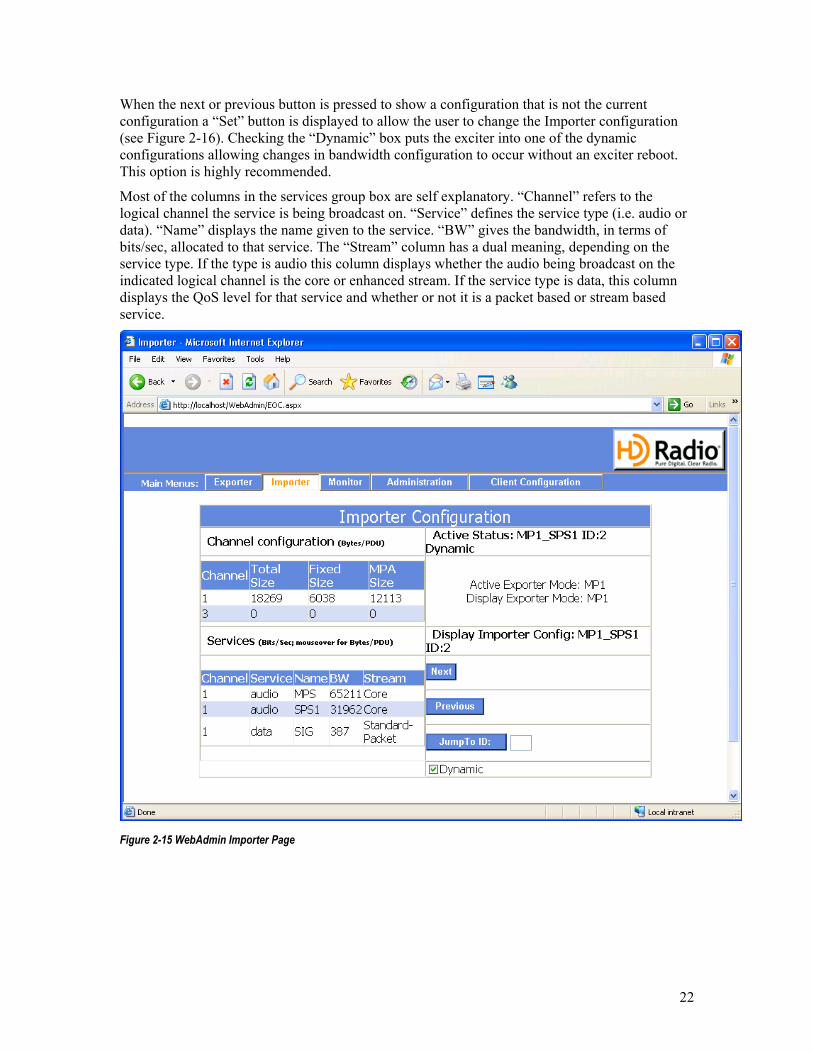
The Importer page, shown in Figure 2-15, displays the Importer configurations and allows the user to change configurations. This page displays the channel configuration as well as what services are associated with that configuration. All Importer configurations are viewable by pressing the next or previous buttons. The default page always shows the current configuration.
22
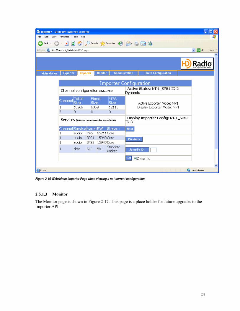
When the next or previous button is pressed to show a configuration that is not the current configuration a “Set” button is displayed to allow the user to change the Importer configuration (see Figure 2-16). Checking the “Dynamic” box puts the exciter into one of the dynamic configurations allowing changes in bandwidth configuration to occur without an exciter reboot. This option is highly recommended.
Most of the columns in the services group box are self explanatory. “Channel” refers to the logical channel the service is being broadcast on. “Service” defines the service type (i.e. audio or data). “Name” displays the name given to the service. “BW” gives the bandwidth, in terms of bits/sec, allocated to that service. The “Stream” column has a dual meaning, depending on the service type. If the type is audio this column displays whether the audio being broadcast on the indicated logical channel is the core or enhanced stream. If the service type is data, this column displays the QoS level for that service and whether or not it is a packet based or stream based service.
Figure 2-15 WebAdmin Importer Page
23
Figure 2-16 WebAdmin Importer Page when viewing a not-current configuration
2.5.1.3 Monitor
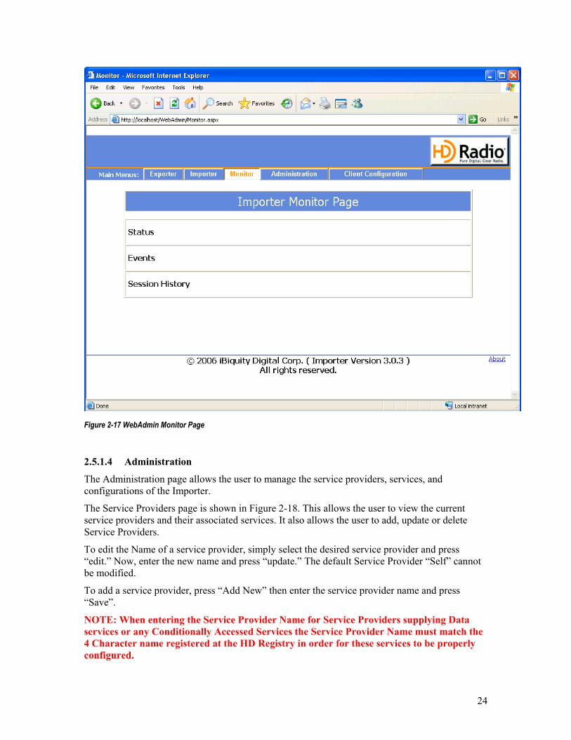
The Monitor page is shown in Figure 2-17. This page is a place holder for future upgrades to the Importer API.
24
Figure 2-17 WebAdmin Monitor Page
2.5.1.4 Administration
The Administration page allows the user to manage the service providers, services, and configurations of the Importer.
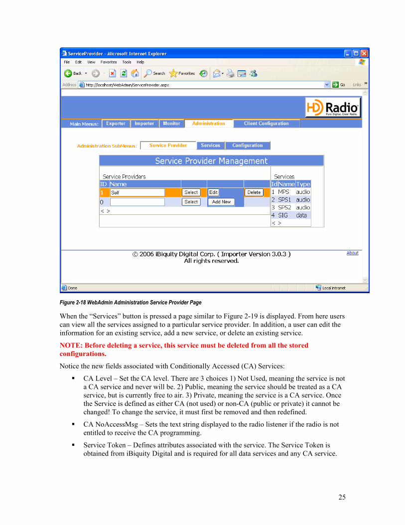
The Service Providers page is shown in Figure 2-18. This allows the user to view the current service providers and their associated services. It also allows the user to add, update or delete Service Providers.
To edit the Name of a service provider, simply select the desired service provider and press “edit.” Now, enter the new name and press “update.” The default Service Provider “Self” cannot be modified.
To add a service provider, press “Add New” then enter the service provider name and press “Save”.
NOTE: When entering the Service Provider Name for Service Providers supplying Data services or any Conditionally Accessed Services the Service Provider Name must match the 4 Character name registered at the HD Registry in order for these services to be properly configured.
25
Figure 2-18 WebAdmin Administration Service Provider Page
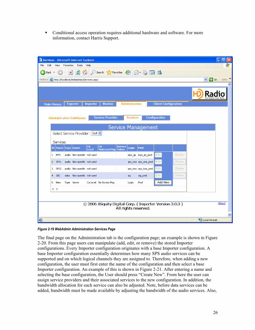
When the “Services” button is pressed a page similar to Figure 2-19 is displayed. From here users can view all the services assigned to a particular service provider. In addition, a user can edit the information for an existing service, add a new service, or delete an existing service.
NOTE: Before deleting a service, this service must be deleted from all the stored configurations.
Notice the new fields associated with Conditionally Accessed (CA) Services:
CA Level – Set the CA level. There are 3 choices 1) Not Used, meaning the service is not a CA service and never will be. 2) Public, meaning the service should be treated as a CA service, but is currently free to air. 3) Private, meaning the service is a CA service. Once the Service is defined as either CA (not used) or non-CA (public or private) it cannot be changed! To change the service, it must first be removed and then redefined.
CA NoAccessMsg – Sets the text string displayed to the radio listener if the radio is not entitled to receive the CA programming.
Service Token – Defines attributes associated with the service. The Service Token is obtained from iBiquity Digital and is required for all data services and any CA service.
26
Conditional access operation requires additional hardware and software. For more information, contact Harris Support.
Figure 2-19 WebAdmin Administration Services Page
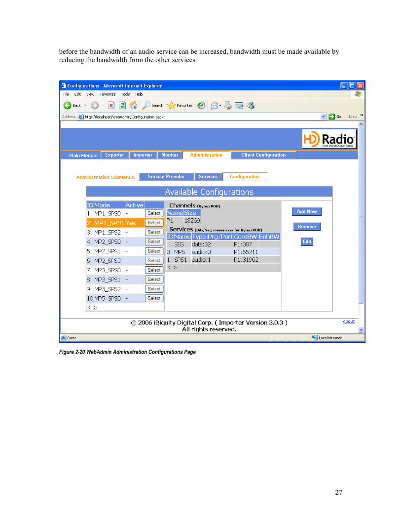
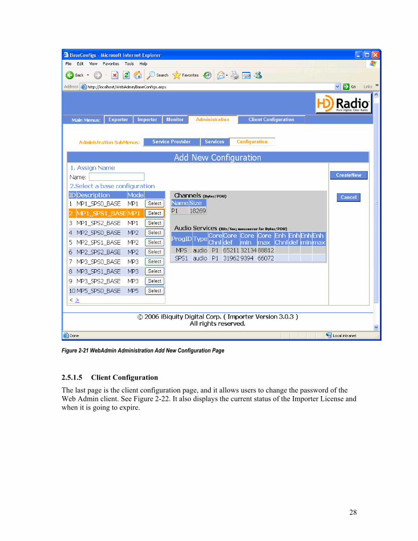
The final page on the Administration tab is the configuration page; an example is shown in Figure 2-20. From this page users can manipulate (add, edit, or remove) the stored Importer configurations. Every Importer configuration originates with a base Importer configuration. A base Importer configuration essentially determines how many SPS audio services can be supported and on which logical channels they are assigned to. Therefore, when adding a new configuration, the user must first enter the name of the configuration and then select a base Importer configuration. An example of this is shown in Figure 2-21. After entering a name and selecting the base configuration, the User should press “Create New”. From here the user can assign service providers and their associated services to the new configuration. In addition, the bandwidth allocation for each service can also be adjusted. Note, before data services can be added, bandwidth must be made available by adjusting the bandwidth of the audio services. Also,
27
before the bandwidth of an audio service can be increased, bandwidth must be made available by reducing the bandwidth from the other services.
Figure 2-20 WebAdmin Administration Configurations Page
28
Figure 2-21 WebAdmin Administration Add New Configuration Page
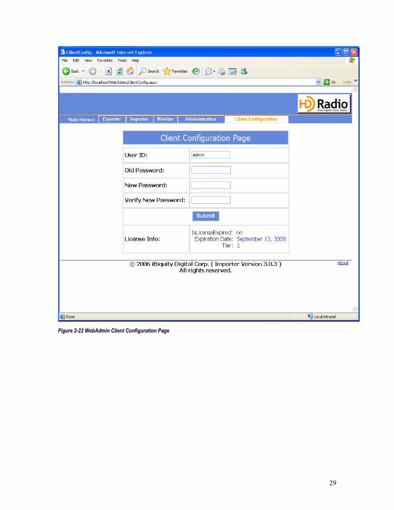
2.5.1.5 Client Configuration
The last page is the client configuration page, and it allows users to change the password of the Web Admin client. See Figure 2-22. It also displays the current status of the Importer License and when it is going to expire.
29
Figure 2-22 WebAdmin Client Configuration Page
30
2.6 Guidelines for Changing Configurations
The Importer allows Administrators the ability to dynamically change configurations either through the WebAdmin (Section 2.5) or the Administrator component (Section 3.1.1), which may or may not have different services associated with the new configuration. The dynamic nature of changing configurations is not totally seamless.
This section provides a few rules and guidelines when switching configurations:
1. When switching between any configurations that are not dynamic, all services or clients must be disconnected and reconnected.
2. When switching between hybrid and all-digital dynamic configurations, all services or clients must be disconnected and reconnected.
3. If a service or client is changing logical channels when configurations are being switched, these services or clients must be disconnected and reconnected.
4. If a data service or client’s bandwidth is being reduced, be aware that significant latencies can occur as the Importer works to transmit all previously requested data packets at the reduced bandwidth
5. Depending on the type of bandwidth change being requested by an SPS service, outages will occur in the SPS service. These outages may last for up to a minute.
31
3 Advanced Operations
3.1 Starting and Running the Importer Components Individually
In some instances, it may be desirable to start the individual Importer applications manually for advanced configuration and troubleshooting. The various Importer components must be started in the correct order and then the desired service provider clients can be connected. The correct starting order is:
1) Administrator 2) Logistics Processor 3) Connection Manager
The stopping order is the reverse of this, or:
1) Connection Manager 2) Logistics Processor 3) Administrator
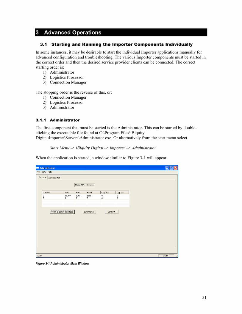
3.1.1 Administrator
The first component that must be started is the Administrator. This can be started by double-clicking the executable file found at C:\Program Files\iBiquity Digital\Importer\Servers\Administrator.exe. Or alternatively from the start menu select
Start Menu -> iBiquity Digital -> Importer -> Administrator When the application is started, a window similar to Figure 3-1 will appear.
Figure 3-1 Administrator Main Window
32
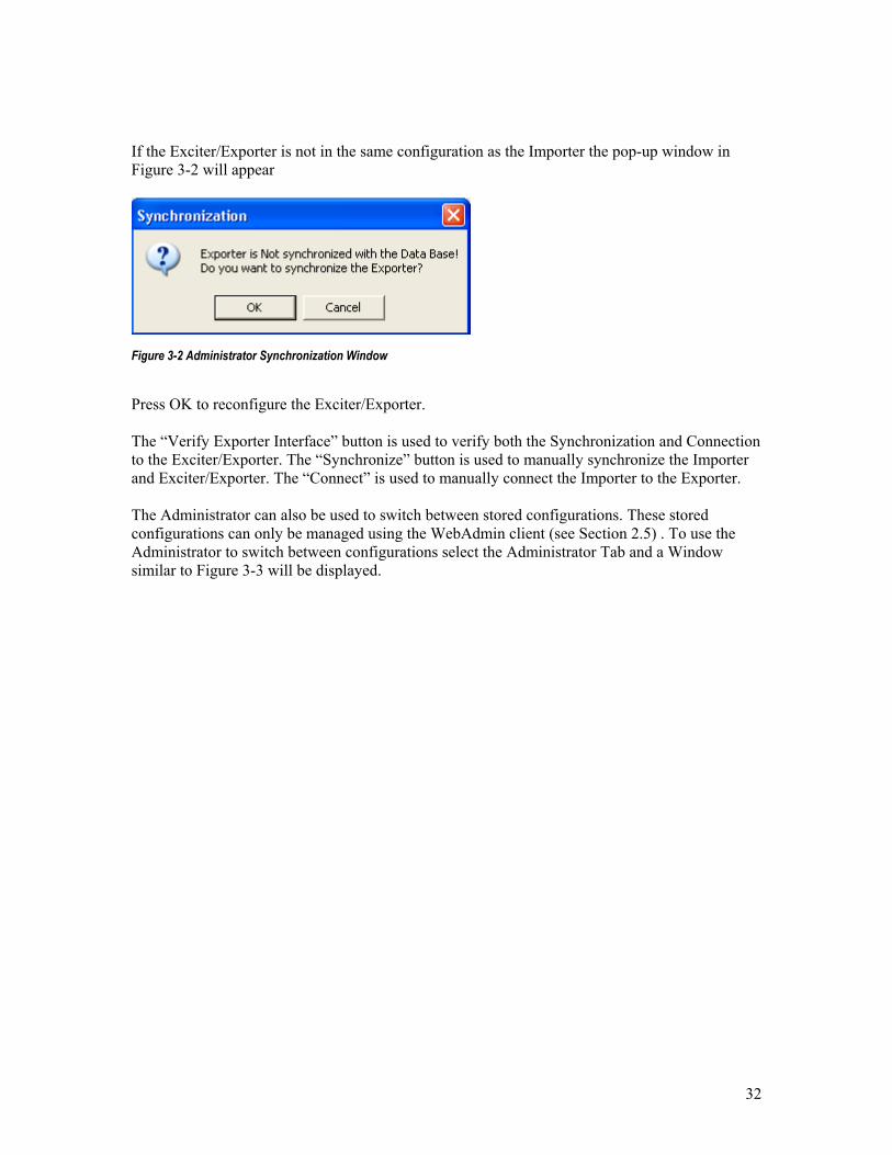
If the Exciter/Exporter is not in the same configuration as the Importer the pop-up window in Figure 3-2 will appear
Figure 3-2 Administrator Synchronization Window
Press OK to reconfigure the Exciter/Exporter. The “Verify Exporter Interface” button is used to verify both the Synchronization and Connection to the Exciter/Exporter. The “Synchronize” button is used to manually synchronize the Importer and Exciter/Exporter. The “Connect” is used to manually connect the Importer to the Exporter. The Administrator can also be used to switch between stored configurations. These stored configurations can only be managed using the WebAdmin client (see Section 2.5) . To use the Administrator to switch between configurations select the Administrator Tab and a Window similar to Figure 3-3 will be displayed.

33
Figure 3-3 Administrator Window, Administrator Tab
This window displays the details of the stored configurations, starting with the current configuration. To display the details of the other configurations, press the Next or Previous buttons. To change the Importer configuration select “Change Configuration.” Checking the Dynamic box puts the Exciter/Exporter in the dynamic scaling and mode changing configurations and is highly recommended.
3.1.2 Logistics Processor
The next component that must be started is the Logistics Processor. This can be started by double-clicking the executable file found at C:\Program Files\iBiquity Digital\Importer\Servers\LogisticsProcessor.exe. Or alternatively from the start menu select
Start Menu -> iBiquity Digital -> Importer -> LogisticsProcessor When the application is started, a window similar to Figure 3-4 will appear.
34
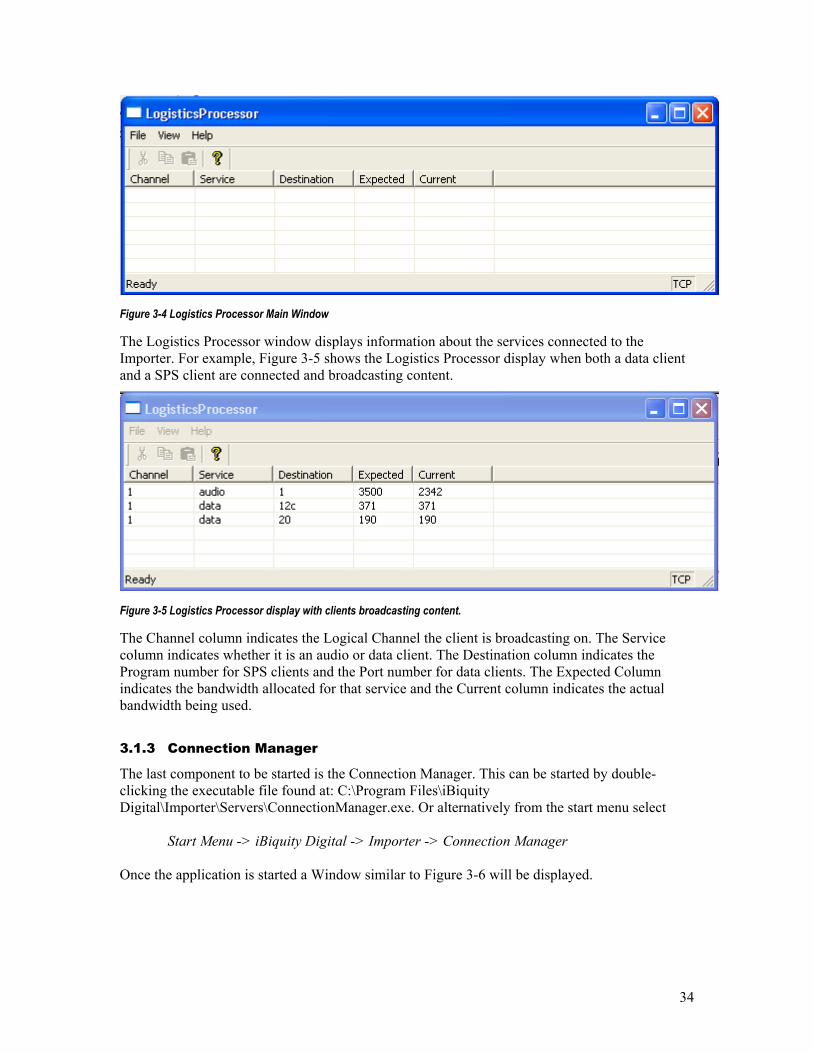
Figure 3-4 Logistics Processor Main Window
The Logistics Processor window displays information about the services connected to the Importer. For example, Figure 3-5 shows the Logistics Processor display when both a data client and a SPS client are connected and broadcasting content.
Figure 3-5 Logistics Processor display with clients broadcasting content.
The Channel column indicates the Logical Channel the client is broadcasting on. The Service column indicates whether it is an audio or data client. The Destination column indicates the Program number for SPS clients and the Port number for data clients. The Expected Column indicates the bandwidth allocated for that service and the Current column indicates the actual bandwidth being used.
3.1.3 Connection Manager
The last component to be started is the Connection Manager. This can be started by double-clicking the executable file found at: C:\Program Files\iBiquity Digital\Importer\Servers\ConnectionManager.exe. Or alternatively from the start menu select
Start Menu -> iBiquity Digital -> Importer -> Connection Manager Once the application is started a Window similar to Figure 3-6 will be displayed.
35
Figure 3-6 Connection Manager Main Window
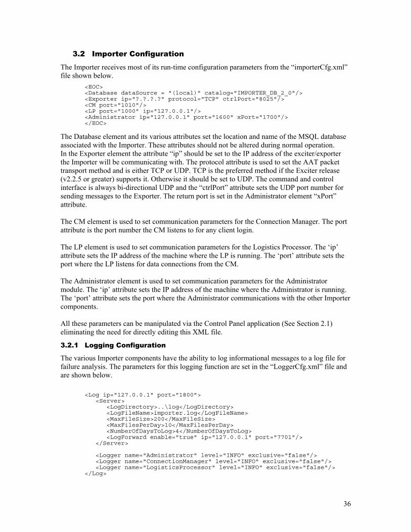
Once client applications connect to the Importer, the Connection Manger window will display the connection information. An example of this is shown in Figure 3-7.
Figure 3-7 Connection Manger Window, after clients have been connected.
36
3.2 Importer Configuration
The Importer receives most of its run-time configuration parameters from the “importerCfg.xml” file shown below.
<EOC> <Database dataSource = "(local)" catalog="IMPORTER_DB_2_0"/> <Exporter ip="?.?.?.?" protocol="TCP" ctrlPort="8025"/> <CM port="1010"/> <LP port="1000" ip="127.0.0.1"/> <Administrator ip="127.0.0.1" port="1600" xPort="1700"/> </EOC>
The Database element and its various attributes set the location and name of the MSQL database associated with the Importer. These attributes should not be altered during normal operation. In the Exporter element the attribute “ip” should be set to the IP address of the exciter/exporter the Importer will be communicating with. The protocol attribute is used to set the AAT packet transport method and is either TCP or UDP. TCP is the preferred method if the Exciter release (v2.2.5 or greater) supports it. Otherwise it should be set to UDP. The command and control interface is always bi-directional UDP and the “ctrlPort” attribute sets the UDP port number for sending messages to the Exporter. The return port is set in the Administrator element “xPort” attribute. The CM element is used to set communication parameters for the Connection Manager. The port attribute is the port number the CM listens to for any client login. The LP element is used to set communication parameters for the Logistics Processor. The ‘ip’ attribute sets the IP address of the machine where the LP is running. The ‘port’ attribute sets the port where the LP listens for data connections from the CM. The Administrator element is used to set communication parameters for the Administrator module. The ‘ip’ attribute sets the IP address of the machine where the Administrator is running. The ‘port’ attribute sets the port where the Administrator communications with the other Importer components. All these parameters can be manipulated via the Control Panel application (See Section 2.1) eliminating the need for directly editing this XML file.
3.2.1 Logging Configuration
The various Importer components have the ability to log informational messages to a log file for failure analysis. The parameters for this logging function are set in the “LoggerCfg.xml” file and are shown below.
<Log ip="127.0.0.1" port="1800"> <Server> <LogDirectory>..\log</LogDirectory> <LogFileName>importer.log</LogFileName> <MaxFileSize>200</MaxFileSize> <MaxFilesPerDay>10</MaxFilesPerDay> <NumberOfDaysToLog>4</NumberOfDaysToLog> <LogForward enable="true" ip="127.0.0.1" port="7701"/> </Server> <Logger name="Administrator" level="INFO" exclusive="false"/> <Logger name="ConnectionManager" level="INFO" exclusive="false"/> <Logger name="LogisticsProcessor" level="INFO" exclusive="false"/> </Log>
37
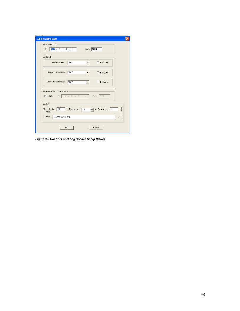
The Log element is used to set the communication parameters for the log service. The IP attribute sets the IP address of the machine the logger is running on. The port attribute sets the port number where the various components send the logging messages. The Server element contains a number of other elements used to set the parameters for the log file management. The LogDirectory element specifies the location of the log file. The LogFileName element specifies the name of the log file. The MaxFileSize element specifies the maximum size of the log file in before it gets archived. The Logger Name element is used to set the log level for the various Importer components. The choices for the level attribute are: OFF, INFO, DEBUG1, DEBUG2, DEBUG3. The exclusive attribute states whether all log messages are printed for the selected level and below (exclusive=”false”) or just for the level selected (exclusive=”true”).
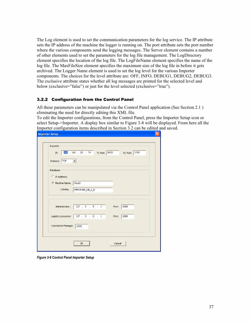
3.2.2 Configuration from the Control Panel
All these parameters can be manipulated via the Control Panel application (See Section 2.1 ) eliminating the need for directly editing this XML file. To edit the Importer configurations, from the Control Panel, press the Importer Setup icon or select Setup->Importer. A display box similar to Figure 3-8 will be displayed. From here all the Importer configuration items described in Section 3.2 can be edited and saved.
Figure 3-8 Control Panel Importer Setup
38
Figure 3-9 Control Panel Log Service Setup Dialog

39
3.3 Database Management
The Users of the Importer may have customized their installation, added their Service Providers, Services, and configurations. This information is stored in the Importer database. The dBAdmin tool is provided so that this information is not lost and can be easily restored in situations where the system has crashed and a reinstall is required or during upgrades of the Importer software. The backups created using this tool should be stored in a safe location away from the Importer, so it is available when required. Backups can be taken manually in a scheduled manner, like once a month, or when major changes have been applied to the Importer configuration.
The Importer database can be backed up/restored or the user configuration information can be saved/merged. This backup and restore feature is used to backup up the Importer database in case of a system failure. The save and merge features are used when updating the Importer software.
The DB Admin tool uses Windows authentication to connect to the Database. This tool should be run on the Importer, by a user belonging to the Administrative group on the computer.
NOTE: When using this tool all other Importer components should be shut down.
To start the DBAdmin tool, run the following application:
C:\Program Files\iBiquity Digital\Importer\servers\DBAdmin.exe or if updating the Importer software, a Save should be performed before the installation, so run the application from the Install directory: C:\Installer\dBAdmin\DBAdmin.exe Once the application is started a window similar to Figure 3-10 will appear. Follow the instructions presented in the ensuing screens to backup, restore, save, or merge the Importer database.
40
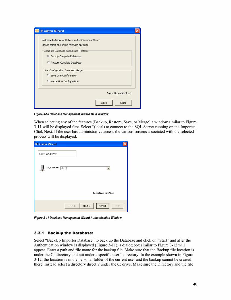
Figure 3-10 Database Management Wizard Main Window.
When selecting any of the features (Backup, Restore, Save, or Merge) a window similar to Figure 3-11 will be displayed first. Select “(local) to connect to the SQL Server running on the Importer. Click Next. If the user has administrative access the various screens associated with the selected process will be displayed.
Figure 3-11 Database Management Wizard Authentication Window.
3.3.1 Backup the Database:
Select “BackUp Importer Database” to back up the Database and click on “Start” and after the Authentication window is displayed (Figure 3-11), a dialog box similar to Figure 3-12 will appear. Enter a path and file name for the backup file. Make sure that the Backup file location is under the C: directory and not under a specific user’s directory. In the example shown in Figure 3-12, the location is in the personal folder of the current user and the backup cannot be created there. Instead select a directory directly under the C: drive. Make sure the Directory and the file
41
name do not contain spaces. Alternately, a Network Drive can also be selected, example “\\server\share”.Click “Next” and a window similar to Figure 3-13 will appear.
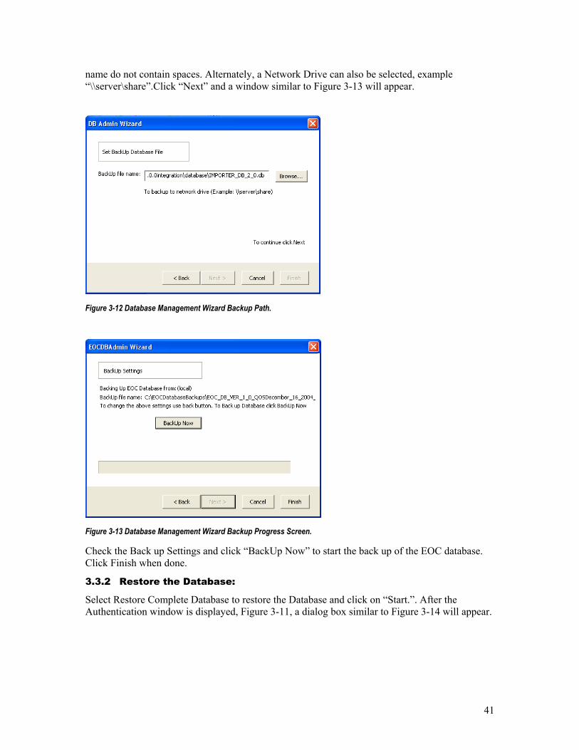
Figure 3-12 Database Management Wizard Backup Path.
Figure 3-13 Database Management Wizard Backup Progress Screen.
Check the Back up Settings and click “BackUp Now” to start the back up of the EOC database. Click Finish when done.
3.3.2 Restore the Database:
Select Restore Complete Database to restore the Database and click on “Start.”. After the Authentication window is displayed, Figure 3-11, a dialog box similar to Figure 3-14 will appear.
42
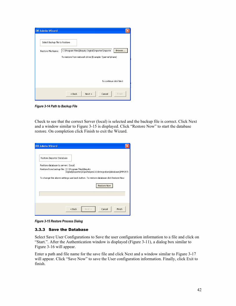
Figure 3-14 Path to Backup File
Check to see that the correct Server (local) is selected and the backup file is correct. Click Next and a window similar to Figure 3-15 is displayed. Click “Restore Now” to start the database restore. On completion click Finish to exit the Wizard.
Figure 3-15 Restore Process Dialog
3.3.3 Save the Database
Select Save User Configurations to Save the user configuration information to a file and click on “Start.”. After the Authentication window is displayed (Figure 3-11), a dialog box similar to Figure 3-16 will appear.
Enter a path and file name for the save file and click Next and a window similar to Figure 3-17 will appear. Click “Save Now” to save the User configuration information. Finally, click Exit to finish.
43
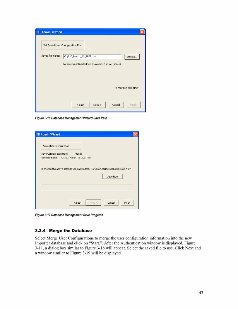
Figure 3-16 Database Management Wizard Save Path
Figure 3-17 Database Management Save Progress
3.3.4 Merge the Database
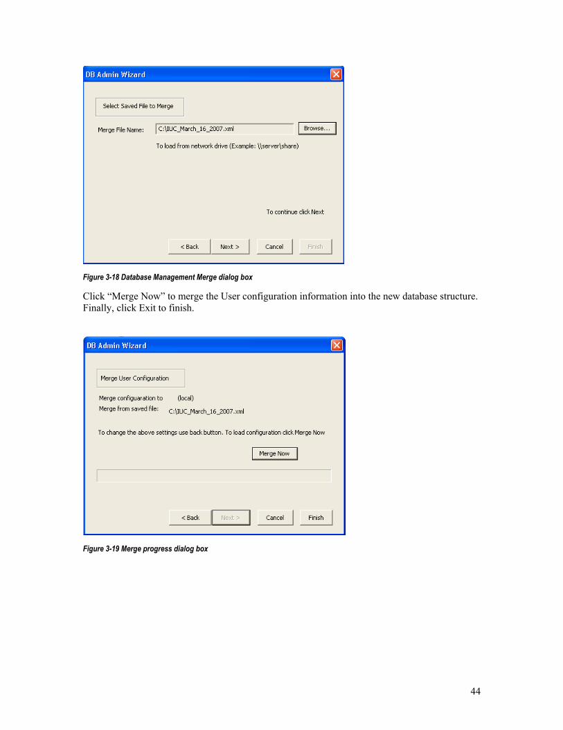
Select Merge User Configurations to merge the user configuration information into the new Importer database and click on “Start.”. After the Authentication window is displayed, Figure 3-11, a dialog box similar to Figure 3-18 will appear. Select the saved file to use. Click Next and a window similar to Figure 3-19 will be displayed.
44
Figure 3-18 Database Management Merge dialog box
Click “Merge Now” to merge the User configuration information into the new database structure. Finally, click Exit to finish.
Figure 3-19 Merge progress dialog box