Embed Size (px)
Citation preview

MM540 Installation Instructions
Please read this entire manual before you begin. Do not unpack any contents until you verify all requirements on PAGE 4.
If you have any questions, visit MantelMount.com or call (800)-897-9755.
Do not let children operate, pull on, or hang from MantelMount. Do not let children push MantelMount upward to the top position - this will cause the mount to slam against the wall due to the upward force of the springs. Only a person tall enough to control the mount all the way to the top should operate MantelMount.
This product contains small parts that can be a choking hazard. Do not let children play with any of these small parts! Keep children away from the work area during installation.
! CAUTION:
Do not use this product in any way, or for any purpose, that is not specifically described in these instructions. MantelMount is not responsible for damage or injury caused by incorrect installation or improper use.
! CAUTION:
MantelMount has four different adjustments that must be made after the installation is complete in order to operate properly.
IMPORTANT:
This product is intended to be installed by professional installation contractors, or persons familiar with the tools and methods required for this installation. If you are not sure about your ability to perform this installation, you must contact a professional. MantelMount is not responsible for damage or injury caused by incorrect installation or improper use.
! CAUTION:
! WARNING!
IMPORTANT SAFETY INSTRUCTIONS - SAVE THESE INSTRUCTIONS
MantelMount MM540 PAGE 1www.MantelMount.com
The bottom travel stop is adjusted with two screws and locknuts so the TV and mount do not lower all the way into the mantel.
Several degrees of tilt in any position can be added or removed by adjusting two knobs, one on each side the swivel mechanism.
The side-to-side swivel stops are adjusted with two screws and locknuts so that the TV
does not swivel into the mantel.
The main bolt adjusts the lifting force to accommodate different TV weights. All TVs
within the weight range should stay in the UP and DOWN positions when adjusted properly
U.S. Pat. No. 8,864,092

PAGE 2 MantelMount MM540
Required Tools Optional Tools1
21 “7/32”10-14mm
4-5mm
Before you begin, please verify that all components are included and undamaged. If any parts are missing or damaged, contact MantelMount. Never proceed with missing or damaged parts!Lay out all components and make sure you identify that each one has a match in the diagram. Some of the parts included will not be used during installation. Do not proceed if you do not understand and identify all of the components.
{02} x4M5x30
{01} x4M5x12
{10} x4M5-M6
{11} x8M8
{12} x8Spacer
{15} x12M6x10
{18} x4M6x40
{03} x4M5x40
{05} x4M6x30
{04} x4M6x16
{06} x4M6x40
{08} x4M8x25
{07} x4M8x15
{09} x4M8x45
{17} x4Lag Bolt
{20} x1Safety Bolt
{27} x1Safety Nut M8
{23} x8Locknut M6
{22} x2Anchor
{24} x4Cable Ties
{14} x4HEX M8x15
{56} x2
{11} x2M8 Washer
{36} x2
{25} x2M8 Nut
OPTIONAL:SIDE SWIVEL KIT
{53} x1CenterHandle
{57} x2Wall Cover
{31} x2VerticalBrace
{30} x2Brace
Extender
{32} x1Wall Plate
{55} x1Horizontal
Brace
{33} x1TV Brace
{35} x1Lifting
Mechanism

MantelMount is designed for use only with decorative fireplaces that are not the primary heat source for a house. Temperature at the front edge of mantle should never exceed 110° F.
A B
C
E
DMantle must not extend from mounting surface more than 16 inches. MantelMount can not extend past a mantel larger than 16 inches. Larger mantels will also reduce the amount of side-to-side swivel.
The space above the mantle must be taller than the TV. The required space depends on how far out the mantle extends. Refer to chart below and add this additional height to the TV height to determine if space is tall enough.
Wall must be WOOD STUD FRAME only. There must be at least 2 studs available for mounting. Wall covering must not exceed 5/8 inch thick.
For other types of walls or other types of installations please visit the FAQ section at www.MantelMount.com.
TELEVISION REQUIREMENTS: 1. Weight must be between 20 - 90 pounds.2. Screen size larger than 44 diagonal inches.3. Mounting screw holes are VESA compliant. For non-VESA hole patterns, please visit the FAQ section at www.MantelMount.com.
Please verify that your installation meets all of these CRITICAL requirements:
110°FMAX.
16 inches MAXIMUM
2 STUDS
If mantle extends:
Less than 8 inches
8 - 10 inches
10 - 12 inches
12 - 16 inches
This is required space height:
TV height plus 5 inches
TV height plus 6 inches
TV height plus 7 inches
TV height plus 9 inches
TV h
eigh
t
Mantle Extends:
Spa
ce h
eigh
t
larger than 44”
VESA Width: 200-700mmHeight: 100-500mm
MantelMount MM540 PAGE 3

1 Use a Vertical Brace {31} to determine if your television is a flat back or an irregular back. An irregular back will require spacers and longer screws to fill any spaces between the Vertical Brace and the TV.The Braces must be parallel to your television screen.
Choose the correct screw diameter and length for the TV. Hand-thread screw combination into the TV to ensure there is adequate thread engagement without hitting the bottom of threaded insert. Use only minimum amount of spacers (if required).
2
3 Possible Screw Combinations shown with maximum spacer usage (if spacers are required).
IMPORTANT INFORMATION: The Vertical Braces {31} are a fixed distance (3 inches) higher than the bottom of the Wall Plate {32}. This relationship can be used to calculate unusual mounting situations such as centering the TV in an alcove or mounting to a specific height on the wall.
4
Flat Back Irregular Back Irregular Back(Recessed Threads)
Spacers
Must leave a gap in threaded TV insert
7-10 threads minimum
engagement
! CAUTION:Do Not use screws that are too long for the threaded inserts of Television. This can damage internal components.
{02}{01}
{10}
{10}
{10}
{10}
{11}
{11}
{11}
{12}
{12}
{10}{12}
{10}{12}
{12}
{12} {12}
{12} {12}
{12}
{12}
{12}
{03}
{05}
{04}
{06}
{08}
{07}
{09}
THREE INCHESFixed Distance
If you measure the distance from the bottom of your TV (or Sound Bar) to the bottom of the Vertical Braces {31} you will automatically know the distance from the bottom of your TV to the bottom of the Wall Plate {32}.
You can use this information to install the Wall Plate on the wall in order to locate the height of your TV to any specific height you desire.
Example: If the Vertical Braces are 6 inches higher than the bottom of your TV, then the Wall Plate will be 3 inches higher than the bottom of your TV when the installation is complete.
If you are installing above a mantel, then your installation must still have the additional clearance for downward motion stated in the chart in Step 9
M5
M6
M8
PAGE 4 MantelMount MM540

5 The Vertical Braces {31} are always mounted higher than the bottom of the TV. However, the Brace Extenders {30} will be mounted one of two ways:
Without a Sound Bar - The Brace Extenders are installed within a few inches above the bottom of the TV.
With a Sound Bar - The Brace Extenders are installed below the TV with enough room to install the Sound Bar onto the Horizontal Brace {34}.
Attach the Vertical Braces {31} to the TV so the bottoms of the Vertical Braces are at least a few inches higher than the bottom of the TV. Centered on the TV is ideal.
Installing the Vertical Braces higher on the TV will allow more downward travel because it allows more clearance between the Lifting Mechanism {35} and the mantel.
6
7 Attach the Extenders with Screws {18} and Nuts {23}.Attach the Horizontal Brace {55} with Screws {15}.Attach the Center Handle {53} with Screws {15}, making sure the Handle is within one inch from the bottom of the TV.
Measure the distance from the bottom of the Vertical Braces {31} (not the Extenders) to the bottom of television or Sound Bar (not the Center Handle).
Write down this distance to use in Step 9.
8
Use this distance in Step 9
Without Sound Bar:
Extenders are1 or 2 inches above the TV
Vertical Braces:Always higher
than the bottomof the TV
WithSound Bar:
Extenders are a few inches below the TV
3 to 10 INCHES
{23}{18}
{15}
{15}
Bottom of Vertical Brace
Bottom of Vertical Brace
Bottom of TV
Bottom ofSound Bar
1 inch MAX (25mm)
MantelMount MM540 PAGE 5

Determine the Vertical Position of the Wall Plate: The image at right shows that the further out a mantle extends, it can interfere with the arc of the lowering TV. MantelMount must be installed a minimum distance above the mantle. This distance is additional to the distance from step 8. See the chart below for the additional height required above the mantle. This dimension will be used in Installation Step 12.
NOTE: If the available wall space above the mantle is close to the required space in the table from “Requirement E” (due to the ceiling, for example) then it is important to use the exact dimensions from this chart. However, if the available wall space above the mantle is much taller than required, then these heights are only minimum requirements.
9
If your mantle extends:
Less than 8 inches
8 - 10 inches
10 - 12 inches
12 - 16 inches
Required Installation Height:
Add 2 inches to the distance from Step 8
Add 3 inches to the distance from Step 8
Add 4 inches to the distance from Step 8
Add 6 inches to the distance from Step 8
USE THIS CHART FOR INSTALLATION STEP 12:
There are four lag bolt holes in the Wall Frame that can not be accessed while the Lifting Mechanism is in the up position. These holes are next to the center hole. If an installation requires access to these holes, the mount must be temporarily installed using other holes so that the mechanism can be pulled down and locked in place with the Safety Bolt and Safety Nut. See step 23. The mount can then be relocated to the correct area.
10 Measure the centerline of the mantle. Mark with tape on the wall.
Locate at least two studs with a stud finder. Locate the center of these studs by using a sharp awl or finish nail poked through the drywall to locate each edge. Lag bolts must be installed into the CENTER of the studs.
11
Cutout shown for reference
CL
PAGE 6 MantelMount MM540

Minimum Height from STEP 9
Align the Wall Plate {32} to two studs above the mantle and position the height using the table in STEP 9. Level the Wall Plate. The Wall Plate might not be centered. Mark the center line of the mantel onto the Wall Plate.
Mark the 4 spots for lag bolts directly onto the centers of the studs.
12 Pre-drill the 4 holes with 7/32” drill bit to a depth of 2.5 inches (65mm) including wall covering. Note: Wall covering (drywall) must not exceed 5/8” thickness.
13
14 Attach the Wall Plate {32} using Lag Bolts {17} and Washers {11} directly into the centers of the studs. 15
! CAUTION:Do Not overtighten Lag Bolts {17}. Tighten only until the washers are firmly against the wall plate. Damage due to overtightening can cause property damage or injury.
Align the center of the Lifting Mechanism {35} to the center mark on the Wall Plate {32}. Install 4 Bolts {14} through the back channels of the Wall Plate into the threaded holes of the Mechanism. Tighten Securely.
DO NOT damage or scratch
the rods of the Gas Springs!
CL
CL
MantelMount MM540 PAGE 7

Determine the desired swivel setting: Installing the Side Swivel Kit:MantelMount MM540 is designed to swivel 35° left and 35° right. Most TVs will reach the wall within this amount of swivel.
For situations where more swivel to one side is desired, MantelMount includes a Side Swivel Kit that will provide 60° of swivel in either the left or right direction, but not both. This situation is only for a small TV and a mounting situation that does not have a mantel.
Note that the “Auto-Straightening” feature does not work with the Swivel Extenders; The TV will need to be manually flattened when raising it to the UP position.
If you do not need to add the Side Swivel Kit, skip ahead to Step 20.
Remove the Swivel TV Plate (Item 34 in the Parts List). Save all of the hardware, it will be re-installed in the same order it is removed.
16 17
Install both Side Swivel Plates {56} onto the Lift Mechanism. The plates nestle underneath the existing tabs. The Screws {36} are installed in the center hole of each Side Swivel Plate.
Re-attach the Swivel TV Plate onto the desired side of the Side Swivel Plates in the same order that each part came off.
18 19
{56}
{11}
{25}
{36}
35˚
60˚
CENTER
RIGHT
LEFT
TV Frame shown for
reference only
60˚35˚
PAGE 8 MantelMount MM540

20 Insert two Cable Tie Anchors {22} into the front holes in the Lower Arm of the Lifting Mechanism. Press firmly until flat.
Shown below is the easiest way to attach cables. Use the included Cable Ties {24} to attach cables so they are sideways to the Lower Arm, making a gentle loop. Cables should be long enough to accommodate the extension and swivel of MantelMount. Check all ranges of motion before tightening the Cable Ties.
21
Reference Only: This is one possible configuration for the signal cables. Each segment of the cables has extra length so that the cables are not stressed or kinked when the mount is moved.
Ensure that cables do not get pinched behind the tilting mechanism when the mount is raised.
{22}
MantelMount MM540 PAGE 9

Install the TV Brace {33} to the Lifting Mechanism {35}.
Level the TV Brace and tighten the 4 screws {15} and Locknuts {23}.22
24 25! WARNING:Do Not put hands into Lifting Mechanism without the Safety Bolt and Safety Nut installed. The power of the Lifting Mechanism can cause bodily injury!
23
Firmly pull down the bottom of the TV Brace until the Lifting Mechanism is in a horizontal position. DO NOT HIT THE MANTLE! The second person must insert the Safety Bolt {20} through the Safety Hole in the Wall Bracket and install the Safety Nut {27}. Slowly release the TV Brace. The Lifting Mechanism should stay at a horizontal position.
THIS STEP REQUIRES TWO PEOPLE
PRE-SET THE LIFTING FORCE:Turn the main bolt CLOCKWISE (while looking at the head of the bolt from underneath) as shown to pull the Gas Springs DOWN for heavy TVs. Rotate the bolt the other way for less lifting force for lighter TVs. See the diagram below for a Pre-Set estimate for the Gas Springs. The lightest lifting force is at the top, and the heaviest is down just below the middle of the bolt threads.
UP
20 lbs45 lbs70 lbs90 lbs
DO NOT adjust all the way to the bottom. That position is only to remove the Gas Springs.
Weight of TV
PAGE 10 MantelMount MM540
DO NOT pullfrom the top

26
Carefully hang the Television onto the TV Brace making sure that all four hooks on the Vertical Braces {31} engage the TV Brace.
DO NOT allow the Television to drop far enough to cause the Lifting Mechanism {35} to hit the mantle.
MantelMount comes pre-adjusted to reduce the possibility of contacting the mantle, but you should always be prepared to remove the television at this stage to make the proper correction.
If the Lifting Mechanism {35} appears to be too close to the mantle, remove television. Go to STEP 29 and make an adjustment to the Bottom Stop position. Repeat this process until the Lifting Mechanism is a safe distance from the mantle when the TV is installed.
THIS STEP REQUIRES TWO PEOPLE
27 Center the TV on the TV Frame and check it with a level.Carefully slide the TV sideways, if required, until it is balanced and horizontal, up to a MAXIMUM OF 2 INCHES left or right.The TV would only need to be moved off-center if it has an unbalanced weight. These are usually older, heavier TVs. If the TV needs to be moved sideways and is visually too much off-center above the mantel, remove the TV and relocate the Wall Plate {32} an equal distance but in the opposite direction of the TV in order to compensate.
28 Install 4 Screws {15} through the TV Brace {33} and into the Vertical Braces {31}.
CL2 inches MAX 2 inches
MAX
MantelMount MM540 PAGE 11
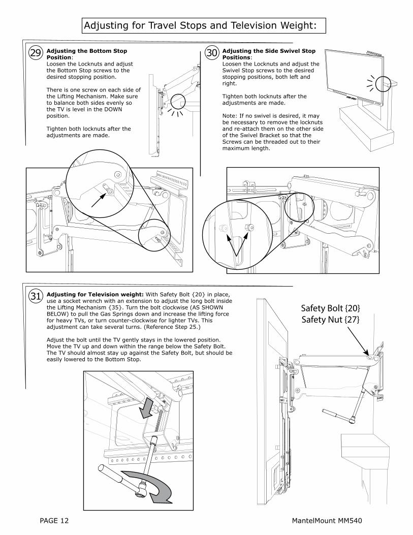
Adjusting the Bottom Stop Position: Loosen the Locknuts and adjust the Bottom Stop screws to the desired stopping position.
There is one screw on each side of the Lifting Mechanism. Make sure to balance both sides evenly so the TV is level in the DOWN position.
Tighten both locknuts after the adjustments are made.
Adjusting the Side Swivel Stop Positions: Loosen the Locknuts and adjust the Swivel Stop screws to the desired stopping positions, both left and right.
Tighten both locknuts after the adjustments are made.
Note: If no swivel is desired, it may be necessary to remove the locknuts and re-attach them on the other side of the Swivel Bracket so that the Screws can be threaded out to their maximum length.
Adjusting for Television weight: With Safety Bolt {20} in place, use a socket wrench with an extension to adjust the long bolt inside the Lifting Mechanism {35}. Turn the bolt clockwise (AS SHOWN BELOW) to pull the Gas Springs down and increase the lifting force for heavy TVs, or turn counter-clockwise for lighter TVs. This adjustment can take several turns. (Reference Step 25.)
Adjust the bolt until the TV gently stays in the lowered position. Move the TV up and down within the range below the Safety Bolt. The TV should almost stay up against the Safety Bolt, but should be easily lowered to the Bottom Stop.
31
29
Adjusting for Travel Stops and Television Weight:
Safety Bolt {20} Safety Nut {27}
30
PAGE 12 MantelMount MM540

Remove the Safety Bolt
and store it for future use.
For wiring inside the Wall Frame, use a Hole Saw drill bit to cut a hole through a Wall Cover {57}. Be careful not to damage the edge around the hole. For best results, support the Wall Cover with scrap wood behind the drilling area.
Paint the Wall Covers {57} if desired and then snap them onto the Wall Frame. The Safety Bolt can now be removed.
Adjusting the Vertical Tilt Position:There are two sliding knobs, one on each side of the Tilt Mechanism, used to set the tilt of the TV. Slightly loosen the knobs and position the TV to the desired tilt, then tighten the knobs. The tilt will stay at the same angle while the mount is raised and lowered, until it is manually changed.
32 33
Never release the handle before it is fully upright. MantelMount is strongest in the top position, and allowing it to slam closed can damage televisions. Always control the lifting process.
! CAUTION: Never allow children to play around or operate MantelMount. Property damage or personal injury can occur.
! CAUTION:
MantelMount MM540 PAGE 13

PAGE 14 MantelMount MM540
59
01 02 03
04 05 06
0710
1112
2027
2417
08 09
Addi
tiona
l Ins
talla
tion
Part
s
38
42 45
41
13
27
26
40
39
46 29
43 44
32
47
20 25
15
54
53
15
15
30
15
56 36 11 25
50
55
1148
1823
36
57
14
1137
25
21
29
28
35
23
31
33
23
11
19
16
2511
25
5819
16
49
34 5229
1051
22

MantelMount MM540 PAGE 15
ITEM
NO.
PART
NUM
BER
DES
CRIP
TIO
NQ
TY.
ITEM
NO.
PART
NUM
BER
DES
CRIP
TIO
NQ
TY.
1 2 3 4 5 6 7 8 9 10 11 12 13 14 15 16 17 18 19 20 21 22 23 24 25 30
31 32 33 34 35 36 37 38 39 40 41 42 43 4544 46 47 48 49 50
26 27 28 29
51 52 53 54 55 56 57 58 59
1218
94
1219
04
1219
14
1219
3
1219
4
4 4
M5
x 12
M5
x 30
M5
x 40
M6
x 16
M6
x 30
1219
74
1219
84 4
1219
9
1219
54
M8
x 15
M8
x 25
M8
x 45
M6
x 40
1216
66
1412
616
1212
28
1413
71
Was
her
M6
Was
her
M8
x 2
Spac
er
Was
her M
8 x
1 x
12
1413
5He
x Bo
lt M
8 x
15
1217
8124
Roun
d He
ad S
crew
M6
x 10
1413
22
Carr
iage
Bol
t M
8 x
120
1215
44
Lag
Bolt
M8
x 60
1411
24
Flan
ge B
ushi
ng
1228
32
Hex
Bolt
M8
x 17
5
1411
0Ca
ble
Tie
Anch
or2
1218
77
Lock
nut M
8
1402
5Sw
ivel
Bra
cket
1
1216
2Ca
ble
Tie
410
1218
62
Nut M
8
1225
02
Rive
t 10
x 7
1412
85
Was
her M
10
1403
82
TV V
ertic
al B
race
1401
01
Wal
l Fra
me
1403
01
TV F
ram
e
1404
91
Swiv
el T
V Pl
ate
1403
61
Wal
l Bra
cket
, Wel
ded
1217
94
1412
02
Roun
d Sc
rew
M8
x 20
Spac
er B
ushi
ng
1404
31
1401
81
Uppe
r Arm
, Wel
ded
Low
er A
rm
1414
21
Hex
Bolt
M8
x 15
0, D
rille
d
1411
51
1303
31
Slid
ing
Bloc
k
Pivo
t Spr
ing
Mou
nt
1224
7D
isk S
prin
g W
ashe
r M8
1225
71 2
Pivo
t Spr
ing
Shaf
t
1225
54
1218
3
Roun
d He
ad S
crew
M6
x 40
Lock
nut M
6
1405
62
Brac
e Ex
tend
er
1413
01
Hex
Bolt
M10
x 3
0
Gas S
prin
g12
160
2
1224
02
Tilt
Knob
M6
1218
5Nu
t M6
1415
52
Tilt
Nut
1405
11
Tilti
ng S
wiv
el T
V Pl
ate
1226
12
Rive
t 10
x 5
1406
01
TV H
orizo
ntal
Bra
ce
1406
21
Cent
er H
andl
e
1222
22
Hand
le R
ubbe
r, Tem
p Ch
ange
1404
72
Side
Sw
ivel
Ext
ende
r Pla
te
2
1415
2
1411
8
Wal
l Cov
er2
Slee
ve1
MM
500M
Inst
ruct
ion
Man
ual
1
1217
4Ca
p Sc
rew
M6
x 10
2
1225
32
Roun
d Sc
rew
M6
x 20

PAGE 16 U.S. Pat. No. 8,864,092 MantleMount MM540
Customer Service: (800)-897-9755
www.MantelMount.com
Exclusive MantelMount
Features! 35°R
60°R
35°L
18.75Max. Clearance
12.5Min. Clearance
34.0
30.0
29.0Maximum Drop
5.7Thickness
8°Tilt
25.0
11.5
21.7
Full Manufacturer Warranty: MantelMount will replace or repair any product or part
that proves defective due to improper workmanship or material during the warranty period.
Visit www.MantelMount.com for details.
Auto-Stabilization:Pivot automatically balances the force of the Gas Springs
so the mount stays level
Auto-Straightening: Flattens the TV as it is raised
to the upper position to prevent rotation into the wall
Smooth Operation:Solid shafts ride inside steel bushings at each pivot point to provide silent movement
Temperature-Sensing Handles: Change to red color at
temperatures above 110ºF to warn users if the �replace
is too hot for TV safety
This Installation Manual is available for download as a PDF document at www.MantelMount.com. The PDF version can be used to see larger images or to zoom in for much greater detail.