Embed Size (px)
Citation preview


IMPORTANT SAFETY INSTRUCTIONSSave these instructions for later use.• Follow all instructions and adhere to warnings marked on the unit and in the operating instructions.• Always use with the correct line voltage. Refer to the manufacturer’s operating instructions for power requirements. Be advised that different operating
voltages may require the use of a different line cord and/or attachment plug.• Do not install the unit in an unventilated rack, or directly above heat producing equipment such as power amplifiers. Observe the maximum ambient
operating temperature listed in the product specification.• Slots and openings on the case are provided for ventilation - to ensure reliable operation and prevent the unit from overheating. Do not block, cover, or insert
objects into the openings. Never spill a liquid of any kind on the unit.• Never attach audio power amplifier outputs directly to any of the unit’s connectors.• To prevent shock or fire hazard, do not expose the unit to rain or moisture, or operate it where it will be exposed to water.• Do not attempt to operate the unit if it has been dropped, damaged, exposed to liquids, or if it exhibits a distinct change in performance indicating the need
for service.• Take precautions not to defeat the grounding or polarization of the unit’s power cord.
• Do not overload wall outlets, extension cords, or integral convenience receptacles, as this can result in a risk of fire or electrical shock.• Route power supply cords so that they are not likely to be walked on or pinched by items placed on or against them, paying particular attention to cords at
plugs, convenience receptacles, and the point at which they exit from the unit.• The unit should be cleaned only as recommended by the manufacturer.• Use an outlet that contains surge suppression ground fault protection. For added protection during a lightning storm, or when the unit is left unattended
and unused for a long period of time, unplug the power cord from the wall outlet. This will provide protection against damage caused by lightning or powerline surges.
CAUTION: RISK OF ELECTRIC SHOCK! DO NOT OPEN!• Do not attempt to service the unit yourself as opening or removing covers may expose you to dangerous voltage, and will void the Limited Warranty. Only
a qualified technician or an authorized lexicon distributor should perform servicing.• To prevent electric shock, do not remove the grounding plug on the power cord, or use any plug or extension cord that does not have a grounding plug
provided.• Make certain that the AC outlet is properly grounded. Do not use an adapter plug for this product.• For continued fire hazard protection, fuses should be replaced ONLY with the exact value and type as indicated on the rear panel or in the user guide.
This triangle, which appears on your component,alerts you to the presence of uninsulated,dangerous voltage inside the enclosure -
voltage that may be sufficient toconstitute a risk of shock.
RISK OF ELECTRIC SHOCKDO NOT OPEN
This triangle, which appears on your component,alerts you to important operating and
maintenance instructions in thisaccompanying literature.
CAUTION
COMMUNICATIONS NOTICEThis equipment has been tested and found to comply with the limits for a Class B digital device, pursuant to Part 15 of the FCC Rules. Theselimits are designed to provide reasonable protection against harmful interference in a residential installation. This equipment generates, uses andcan radiate radio frequency energy and, if not installed and used in accordance with manufacturer’s instructions, may cause harmful interferenceto radio communications. However, there is no guarantee that interference will not occur in a particular installation. If this equipment does causeharmful interference to radio or television reception, which can be determined by turning the equipment off and on, the user is encouraged to tryto correct the interference by one or more of the following measures:• Reorient the receiving antenna.• Relocate the computer with respect to the receiver.• Move the computer away from the receiver.• Plug the computer into a different outlet so that the computer and receiver are on different branch circuits.
If necessary, the user should consult the dealer or an experienced radio/television technician for additional suggestions. The user may find thefollowing booklet prepared by the Federal Communications Commission helpful: "How to identify and Resolve Radio/TV Interference Problems."This booklet is available from the U.S. Government Printing Office, Washington, DC 20402, Stock No. 004-000-00345-4.
A Harman International Company
Lexicon, Inc.3 Oak ParkBedford, MA 01730-1441 USATel 781-280-0300Fax 781-280-0490www.lexicon.com
Customer SupportTel 781-280-0300Fax 781-280-0495 (Sales)Fax 781-280-0499 (Service)
Lexicon Part No. 070-14912 | Rev 1 | 02/02
© 2002 Lexicon, Inc. All rights reserved.
This document should not be construed as a commitment on the part of Lexicon, Inc. The information it contains is subject to changewithout notice. Lexicon, Inc. assumes no responsibility for errors that may appear within this document.
Introduction Lexicon
ii
Introduction
Important Safety Instructions. . . . . . . . . . . . . . . iv
Wichtige Sicherheitshinweise . . . . . . . . . . . . . . . iv
Instrucciones de seguridad importantes . . . . . . . v
Instructions importantes relatives à la sécurité . . . v
Importanti norme di sicurezza . . . . . . . . . . . . . . vi
Instruções Importantes de Segurança. . . . . . . . . vi
Vigtig Information om Sikkerhed . . . . . . . . . . . .vii
Tärkeitä Turvallisuusohjeita . . . . . . . . . . . . . . . .vii
Viktig Informasjon om Sikkerhet . . . . . . . . . . . .viii
Viktiga Säkerhetsföreskrifter . . . . . . . . . . . . . . .viii
Important User Information. . . . . . . . . . . . . . . . ix
Wichtige Benutzerinformation . . . . . . . . . . . . . . x
Información importante para el usuario . . . . . . . xi
Important - Informations Utilisateur . . . . . . . . . xii
Importanti informazioni per l’utente. . . . . . . . . xiii
Informações Importantes ao usuário. . . . . . . . . xiv
Section 1: Getting Started
About the MPX 550 . . . . . . . . . . . . . . . . . . . . . . . . 1-2Highlights
Front Panel Overview . . . . . . . . . . . . . . . . . . . . . . . 1-4Front Panel Display
Rear Panel Overview . . . . . . . . . . . . . . . . . . . . . . . 1-8
Connecting the Unit . . . . . . . . . . . . . . . . . . . . . . 1-10Footswitch • Typical Connections to a Console
Setting Audio Levels . . . . . . . . . . . . . . . . . . . . . . . 1-12Input • Output
Section 2: Basic Operation
Selecting and Loading Programs. . . . . . . . . . . . . . . 2-2
Editing Programs . . . . . . . . . . . . . . . . . . . . . . . . . . 2-3
The "Adjust" Parameter. . . . . . . . . . . . . . . . . . . . . . 2-3
Storing Programs . . . . . . . . . . . . . . . . . . . . . . . . . . 2-4
The Compressor . . . . . . . . . . . . . . . . . . . . . . . . . . 2-5
Tap Tempo . . . . . . . . . . . . . . . . . . . . . . . . . . . . . . 2-6Matching Rhythm • Audio Tap • Global Tempo
Bypass. . . . . . . . . . . . . . . . . . . . . . . . . . . . . . . . . . 2-7
FR
IT
PT
ES
DE
US
DK
FI
NO
SE
FR
IT
PT
ES
DE
US

IntroductionMPX 550
iii
Section 3: System Mode
System Mode Functions . . . . . . . . . . . . . . . . . . . . . 3-2Parameters • MIDI Dumps • Restore Default Commands
Section 4: Program Descriptions
Single Programs. . . . . . . . . . . . . . . . . . . . . . . . . . . 4-2Plate • Gate/Inv • Hall • Chamber • Ambience • Room •Tremolo • Rotary • Chorus • Flange • Detune • Pitch • Dly/Eko
Special FX . . . . . . . . . . . . . . . . . . . . . . . . . . . . . . 4-16Stereo Stage
Dual Programs . . . . . . . . . . . . . . . . . . . . . . . . . . . 4-18Efx Bal • Flng-Dly • Pch-Dly • Chor-Dly • Dly-Rvb • Flng-Rvb •Pch-Rvb • Chor-Rvb • MSplit Dly • MSplit Rvb • Dual Mono
Cmprssr. . . . . . . . . . . . . . . . . . . . . . . . . . . . . . . . 4-31
Dynamics . . . . . . . . . . . . . . . . . . . . . . . . . . . . . . 4-32Peak Expansion • Compression • Tape Saturation • Level Meters •Typical Mastering Dynamics Control Adjustments
Live-FOH (Front of House) . . . . . . . . . . . . . . . . . . 4-36
Section 5: Parameter Descriptions
Parameter Graphics . . . . . . . . . . . . . . . . . . . . . . . . 5-2
Parameter Glossary . . . . . . . . . . . . . . . . . . . . . . . . 5-4
Section 6: MIDI Operation
Learn Mode. . . . . . . . . . . . . . . . . . . . . . . . . . . . . . 6-2
MIDI Channel Assignment . . . . . . . . . . . . . . . . . . . 6-2
Program Change Messages . . . . . . . . . . . . . . . . . . 6-3Loading Programs • Activating Bypass or Tap Functions
Continuous Controllers. . . . . . . . . . . . . . . . . . . . . . 6-4
MIDI Clock . . . . . . . . . . . . . . . . . . . . . . . . . . . . . . 6-6
MIDI Dumps . . . . . . . . . . . . . . . . . . . . . . . . . . . . . 6-6
Sysex Messages . . . . . . . . . . . . . . . . . . . . . . . . . . . 6-7
MIDI Implementation Chart . . . . . . . . . . . . . . . . . . 6-8
Appendix
Specifications. . . . . . . . . . . . . . . . . . . . . . . . . . . . . A-2
Declaration of Conformity . . . . . . . . . . . . . . . . . . . A-3
Index
Introduction Lexicon
iv
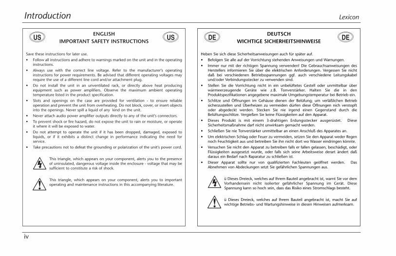
ENGLISHIMPORTANT SAFETY INSTRUCTIONS
Save these instructions for later use.
• Follow all instructions and adhere to warnings marked on the unit and in the operatinginstructions.
• Always use with the correct line voltage. Refer to the manufacturer’s operatinginstructions for power requirements. Be advised that different operating voltages mayrequire the use of a different line cord and/or attachment plug.
• Do not install the unit in an unventilated rack, or directly above heat producingequipment such as power amplifiers. Observe the maximum ambient operatingtemperature listed in the product specification.
• Slots and openings on the case are provided for ventilation - to ensure reliableoperation and prevent the unit from overheating. Do not block, cover, or insert objectsinto the openings. Never spill a liquid of any kind on the unit.
• Never attach audio power amplifier outputs directly to any of the unit’s connectors.
• To prevent shock or fire hazard, do not expose the unit to rain or moisture, or operateit where it will be exposed to water.
• Do not attempt to operate the unit if it has been dropped, damaged, exposed toliquids, or if it exhibits a distinct change in performance indicating the need forservice.
• Take precautions not to defeat the grounding or polarization of the unit’s power cord.
This triangle, which appears on your component, alerts you to the presenceof uninsulated, dangerous voltage inside the enclosure - voltage that may besufficient to constitute a risk of shock.
This triangle, which appears on your component, alerts you to importantoperating and maintenance instructions in this accompanying literature.
US USDEUTSCH
WICHTIGE SICHERHEITSHINWEISE
Heben Sie sich diese Sicherheitsanweisungen auch für später auf.
• Befolgen Sie alle auf der Vorrichtung stehenden Anweisungen und Warnungen.
• Immer nur mit der richtigen Spannung verwenden! Die Gebrauchsanweisungen desHerstellers informieren Sie über die elektrischen Anforderungen. Vergessen Sie nichtdaß bei verschiedenen Betriebsspannungen ggf. auch verschiedene Leitungskabelund/oder Verbindungsstecker zu verwenden sind.
• Stellen Sie die Vorrichtung nicht in ein unbelüftetes Gestell oder unmittelbar überwärmeerzeugende Geräte wie z.B. Tonverstärker. Halten Sie die in denProduktspezifikationen angegebene maximale Umgebungstemperatur bei Betrieb ein.
• Schlitze und Öffnungen im Gehäuse dienen der Belüfung; um verläßlichen Betriebsicherzustellen und Überheizen zu vermeiden dürfen diese Öffnungen nich verstopftoder abgedeckt werden. Stecken Sie nie irgend einen Gegenstand durch dieBelüftungsschlitze. Vergießen Sie keine Flüssigkeiten auf den Apparat.
• Dieses Produkt is mit einem 3-drahtigen Erdungsstecker ausgerüstet. DieseSicherheitsmaßnahme darf nicht unwirksam gemacht werden.
• Schließen Sie nie Tonverstärker unmittelbar an einen Anschluß des Apparates an.
• Um elektrischen Schlag oder Feuer zu vermeiden, setzen Sie den Apparat weder Regennoch Feuchtigkeit aus und betreiben Sie ihn nicht dort wo Wasser eindringen könnte.
• Versuchen Sie nicht den Apparat zu betreiben falls er fallen gelassen, beschädigt, oderFlüssigkeiten ausgesetzt wurde, oder falls sich seine Arbeitsweise derart ändert daßdaraus ein Bedarf nach Raparatur zu schließen ist.
• Dieser Apparat sollte nur von qualifizierten Fachleuten geöffnet werden. DasAbnehmen von Abdeckungen setzt Sie gefährlichen Spannungen aus.
ü Dieses Dreieck, welches auf Ihrem Bauteil angebracht ist, warnt Sie vor demVorhandensein nicht isolierter gefährlicher Spannung im Gerät. DieseSpannung kann so hoch sein, dass das Risiko eines Stromschlags besteht.
ü Dieses Dreieck, welches auf Ihrem Bauteil angebracht ist, macht Sie aufwichtige Betriebs- und Wartungshinweise in diesen Hinweisen aufmerksam.
DE DE
IntroductionMPX 550
v
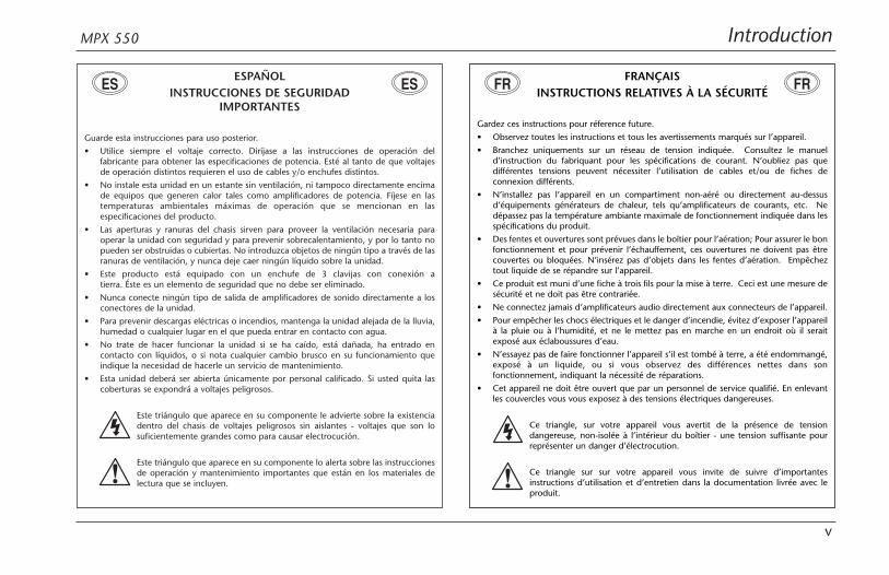
ESPAÑOLINSTRUCCIONES DE SEGURIDAD
IMPORTANTES
Guarde esta instrucciones para uso posterior.
• Utilice siempre el voltaje correcto. Diríjase a las instrucciones de operación delfabricante para obtener las especificaciones de potencia. Esté al tanto de que voltajesde operación distintos requieren el uso de cables y/o enchufes distintos.
• No instale esta unidad en un estante sin ventilación, ni tampoco directamente encimade equipos que generen calor tales como amplificadores de potencia. Fíjese en lastemperaturas ambientales máximas de operación que se mencionan en lasespecificaciones del producto.
• Las aperturas y ranuras del chasis sirven para proveer la ventilación necesaria paraoperar la unidad con seguridad y para prevenir sobrecalentamiento, y por lo tanto nopueden ser obstruidas o cubiertas. No introduzca objetos de ningún tipo a través de lasranuras de ventilación, y nunca deje caer ningún líquido sobre la unidad.
• Este producto está equipado con un enchufe de 3 clavijas con conexión atierra. Éste es un elemento de seguridad que no debe ser eliminado.
• Nunca conecte ningún tipo de salida de amplificadores de sonido directamente a losconectores de la unidad.
• Para prevenir descargas eléctricas o incendios, mantenga la unidad alejada de la lluvia,humedad o cualquier lugar en el que pueda entrar en contacto con agua.
• No trate de hacer funcionar la unidad si se ha caído, está dañada, ha entrado encontacto con líquidos, o si nota cualquier cambio brusco en su funcionamiento queindique la necesidad de hacerle un servicio de mantenimiento.
• Esta unidad deberá ser abierta únicamente por personal calificado. Si usted quita lascoberturas se expondrá a voltajes peligrosos.
Este triángulo que aparece en su componente le advierte sobre la existenciadentro del chasis de voltajes peligrosos sin aislantes - voltajes que son losuficientemente grandes como para causar electrocución.
Este triángulo que aparece en su componente lo alerta sobre las instruccionesde operación y mantenimiento importantes que están en los materiales delectura que se incluyen.
ES ESFRANÇAIS
INSTRUCTIONS RELATIVES À LA SÉCURITÉ
Gardez ces instructions pour réference future.
• Observez toutes les instructions et tous les avertissements marqués sur l’appareil.
• Branchez uniquements sur un réseau de tension indiquée. Consultez le manueld’instruction du fabriquant pour les spécifications de courant. N’oubliez pas quedifférentes tensions peuvent nécessiter l’utilisation de cables et/ou de fiches deconnexion différents.
• N’installez pas l’appareil en un compartiment non-aéré ou directement au-dessusd’équipements générateurs de chaleur, tels qu’amplificateurs de courants, etc. Nedépassez pas la température ambiante maximale de fonctionnement indiquée dans lesspécifications du produit.
• Des fentes et ouvertures sont prévues dans le boîtier pour l’aération; Pour assurer le bonfonctionnement et pour prévenir l’échauffement, ces ouvertures ne doivent pas êtrecouvertes ou bloquées. N’insérez pas d’objets dans les fentes d’aération. Empêcheztout liquide de se répandre sur l’appareil.
• Ce produit est muni d’une fiche à trois fils pour la mise à terre. Ceci est une mesure desécurité et ne doit pas être contrariée.
• Ne connectez jamais d’amplificateurs audio directement aux connecteurs de l’appareil.
• Pour empêcher les chocs électriques et le danger d’incendie, évitez d’exposer l’appareilà la pluie ou à l’humidité, et ne le mettez pas en marche en un endroit où il seraitexposé aux éclaboussures d’eau.
• N’essayez pas de faire fonctionner l’appareil s’il est tombé à terre, a été endommangé,exposé à un liquide, ou si vous observez des différences nettes dans sonfonctionnement, indiquant la nécessité de réparations.
• Cet appareil ne doit être ouvert que par un personnel de service qualifié. En enlevantles couvercles vous vous exposez à des tensions électriques dangereuses.
Ce triangle, sur votre appareil vous avertit de la présence de tensiondangereuse, non-isolée à l’intérieur du boîtier - une tension suffisante pourreprésenter un danger d’électrocution.
Ce triangle sur sur votre appareil vous invite de suivre d’importantesinstructions d’utilisation et d’entretien dans la documentation livrée avec leproduit.
FR FR

Introduction Lexicon
vi
PORTUGUESEINSTRUÇÕES DE SEGURANÇA IMPORTANTES
Economize estas instruções para uso posterior.
• Siga todas as instruções e advertências marcadas na unidade.
• Sempre use com a voltagem de linha correta. Se refira ao fabricante está operandoinstruções para as exigências de poder. Seja aconselhado que voltagens operacionaisdiferentes requeiram para o uso uma corda de linha diferente ou tomada de anexo.
• Não instale esta unidade em uma prateleira de unventilated, nem diretamente sobreartigos que geram calor, como amplificadores de poder. Observe o máximo quetemperatura operacional ambiente listou na especificação de produto.
• São providas as aberturas no caso para ventilação; assegurar operação segura e impediristo de aquecer demais, não devem ser bloqueadas estas aberturas ou devem sercobertas. Nunca empurre objetos de qualquer amável por quaisquer das aberturas deventilação. Nunca derrame qualquer líquido na unidade.
• Nunca prenda amplificador de poder auditivo produz diretamente a quaisquer dosconectores da unidade.
• Prevenir choque ou perigo de incêndio, não exponha a unidade para chover ouumidade, ou opera isto onde será exposto a umidade. Não tente operar a unidade sefoi derrubado, estragado, exposto a líquidos, ou se exibe uma mudança distinta emdesempenho que indica a necessidade por serviço. Esta unidade só deveria ser abertaatravés de pessoal de serviço qualificado. Removendo coberturas o exporão a voltagensperigosas.
Este triângulo que se aparece em seu componente o alerta à presença deuninsulated, voltagem perigosa dentro do enclosure - voltage que pode sersuficiente para constituir um risco de choque.
Este triângulo que se aparece em seu componente o alerta a operandoimportantes e instruções de manutenção nesta literatura acompanhante.
PT PTITALIANO
IMPORTANTI NORME DI SICUREZZA
Conservare le presenti norme per l’utilizzo futuro.• Osservare tutte le istruzioni e le avvertenze apposte sull’unità.• Utilizzare esclusivamente con la tensione di rete corretta. Consultare le istruzioni
operative fornite dal fabbricante per i dati riguardanti la tensione e l’assorbimento dicorrente. Potrebbe essere necessario l’uso di cavi di rete e/o di spine diverse a secondadella tensione utilizzata.
• Non installare l’unità in uno scaffale privo di ventilazione oppure direttamente soprauna fonte di calore, come, ad esempio, un amplificatore. Non superare la temperaturaambientale massima di funzionamento riportata nei dati tecnici del prodotto.
• Le fessure e le altre aperture nella scatola servono alla ventilazione. Per unfunzionamento affidabile, e per evitare un eventuale surriscaldamento, queste aperturenon vanno ostruite o coperte in nessun modo. Evitare in tutti i casi di inserire oggettidi qualsiasi genere attraverso le fessure di ventilazione. Non versare mai del liquido dinessun tipo sull’unità.
• Questo prodotto viene fornito con una spina a 3 fili con massa. Tale dispositivo disicurezza non va eliminato.
• Evitare sempre di collegare le uscite dell’amplificatore audio direttamente ai connettoridell’unità.
• Per prevenire il pericolo di folgorazione e di incendio non esporre l’unità alla pioggia oad un’umidità eccessiva; evitare di adoperare l’unità dove potrebbe entrare in contattocon acqua.
• Evitare di adoperare l’unità se la stessa è stata urtata violentemente, se ha subito undanno, se è stata esposta ad un liquido o in caso di un evidente cambiamento delleprestazioni che indichi la necessità di un intervento di assistenza tecnica.
• Ogni intervento sull’unità va eseguito esclusivamente da personale qualificato. Larimozione della copertura comporta l’esposizione al pericolo di folgorazione.
Il presente triangolo impresso sul componente avverte della presenza ditensioni pericolose non isolate all’interno della copertura - tali tensionirappresentano un pericolo di folgorazione.
Il presente triangolo impresso sul componente avverte l’utente della presenzanella documentazione allegata di importanti istruzioni relative al funzionaento ed alla manutenzione.
IT IT

IntroductionMPX 550
vii
DANSKVIGTIG INFORMATION OM SIKKERHED
Gem denne vejledning til senere brug.
• Følg alle anvisninger og advarsler på apparatet.
• Apparatet skal altid tilsluttes den korrekte spænding. Der henvises til brugsanvisningen,der indeholder specifikationer for strømforsyning. Der gøres opmærksom på, at vedvarierende driftsspændinger kan det blive nødvendigt at bruge andre lednings- og/ellerstiktyper.
• Apparatet må ikke monteres i et kabinet uden ventilation eller lige over andet udstyr,der udvikler varme, f.eks. forstærkere. Den maksimale omgivelsestemperatur ved drift,der står opført i specifikationerne, skal overholdes.
• Der er ventilationsåbninger i kabinettet. For at sikre apparatets drift og hindreoverophedning må disse åbninger ikke blokeres eller tildækkes. Stik aldrig noget indigennem ventilationsåbningerne, og pas på aldrig at spilde nogen form for væske påapparatet.
• Dette apparat er forsynet med et stik med jordforbindelse. Denne sikkerhedsforanstaltning må aldrig omgås.
• Udgangsstik fra audioforstærkere må aldrig sættes direkte i apparatet.
• Apparatet må ikke udsættes for regn eller fugt og må ikke bruges i nærheden af vandfor at undgå risiko for elektrisk stød og brand.
• Apparatet må aldrig bruges, hvis det er blevet stødt, beskadiget eller vådt, eller hvisændringer i ydelsen tyder på, at det trænger til eftersyn.
• Dette apparat må kun åbnes af fagfolk. Hvis dækslet tages af, udsættes man for livsfarlighøjspænding.
Denne mærkat på komponenten advarer om uisoleret, farlig spænding iapparatet - høj nok til at give elektrisk stød.
Denne mærkat på komponenten advarer om vigtig driftsog vedligeholdsin-formation i den tilhørende litteratur.
SUOMITÄRKEITÄ TURVALLISUUSOHJEITA
Säilytä nämä ohjeet tulevaa käyttöä varten.
• Seuraa kaikkia yksikköön merkittyjä ohjeita ja varoituksia.
• Käytä aina oikeaa verkkojännitettä. Tehovaatimukset selviävät valmistajankäyttöohjeista. Huomaa, että eri käyttöjännitteet saattavat vaatia toisenlaisenverkkojohdon ja/tai -pistokkeen käytön.
• Älä asenna yksikköä telineeseen jossa ei ole tuuletusta, tai välittömästi lämpöätuottavien laitteiden, esim. tehovahvistimien, yläpuolelle. Ympäristön lämpötilakäytössä ei saa ylittää tuotespesifikaation maksimilämpötilaa.
• Kotelo on varustettu tuuletusreiillä ja -aukoilla. Luotettavan toiminnan varmistamiseksija ylilämpenemisen välttämiseksi näitä aukkoja ei saa sulkea tai peittää. Mitään esineitäei saa työntää tuuletusaukkoihin. Mitään nesteitä ei saa kaataa yksikköön.
• Tuote on varustettu 3-johtimisella maadoitetulla verkkopistokkeella. Tämä onturvallisuustoiminne eikä sitä saa poistaa.
• Älä kytke audiotehovahvistimen lähtöjä suoraan mihinkään yksikön liittimeen.
• Sähköiskun ja palovaaran välttämiseksi yksikkö ei saa olla sateessa tai kosteassa, eikä sitäsaa käyttää märässä ympäristössä.
• Älä käytä yksikköä jos se on pudonnut, vaurioitunut, kostunut, tai jos sen suorituskykyon huomattavasti muuttunut, mikä vaatii huoltoa.
• Yksikön saa avata vain laitteeseen perehtynyt huoltohenkilö. Kansien poisto altistaasinut vaarallisille jännitteille.
Tämä kolmio, joka esiintyy komponentissasi, varoittaa sinua eristämättömänvaarallisen jännitteen esiintymisestä yksikön sisällä. Tämä jännite saattaa ollariittävän korkea aiheuttamaan sähköiskuvaaran.
Tämä kolmio, joka esiintyy komponentissasi, kertoo sinulle, että tässätuotedokumentoinnissa esiintyy tärkeitä käyttö- ja ylläpito-ohjeita.
FIDK DK FI

Introduction Lexicon
viii
NORSKVIKTIG INFORMASJON OM SIKKERHET
Ta vare på denne veiledningen for senere bruk.
• Følg alle anvisningene og advarslene som er angitt på apparatet.
• Apparatet skal alltid anvendes med korrekt spenning. Produktbeskrivelsen inneholderspesifikasjoner for strømkrav. Vær oppmerksom på at det ved ulike driftsspenninger kanvære nødvendig å bruke en annen ledning- og/eller støpseltype.
• Apparatet skal ikke monteres i skap uten ventilasjon, eller direkte overvarmeproduserende utstyr, som for eksempel kraftforsterkere. Den maksimaleromtemperaturen som står oppgitt i produktbeskrivelsen, skal overholdes.
• Apparatet er utstyrt med ventilasjonsåpninger. For at apparatet skal være pålitelig i brukog ikke overopphetes, må disse åpningene ikke blokkeres eller tildekkes. Stikk aldri noeinn i ventilasjonsåpningene, og pass på at det aldri søles noen form for væske påapparatet.
• Dette apparatet er utstyrt med et jordet støpsel. Dette er en sikkerhetsforanstaltningsom ikke må forandres.
• Utgangsplugger fra audioforsterkere skal aldri koples direkte til apparatet.
• Unngå brannfare og elektrisk støt ved å sørge for at apparatet ikke utsettes for regn ellerfuktighet og ikke anvendes i nærheten av vann.
• Apparatet skal ikke brukes hvis det har blitt utsatt for støt, er skadet eller blitt vått, ellerhvis endringer i ytelsen tyder på at det trenger service.
• Dette apparatet skal kun åpnes av fagfolk. Hvis dekselet fjernes, utsettes man forlivsfarlig høyspenning.
Komponenten er merket med denne trekanten, som er en advarsel om at detfinnes uisolert, farlig spenning inne i kabinettet - høy nok til å utgjøre en farefor elektrisk støt.
Komponenten er merket med denne trekanten, som betyr at den tilhørendelitteraturen inneholder viktige opplysninger om drift og ved
SVENSKAVIKTIGA SÄKERHETSFÖRESKRIFTER
Spara dessa föreskrifter för framtida bruk.
• Följ alla anvisningar och varningar som anges på enheten.
• Använd alltid rätt nätspänning. Se tillverkarens bruksanvisningar för information omeffektkrav. Märkväl, att andra matningsspänningar eventuellt kräver att en annan typsnätsladd och/eller kontakt används.
• Installera inte enheten i ett oventilerat stativ, eller direkt ovanför utrustningar som avgervärme, t ex effektförstärkare. Se till att omgivningens temperatur vid drift inteöverskrider det angivna värdet i produktspecifikationen.
• Behållaren är försedd med hål och öppningar för ventilering. För att garanteratillförlitlig funktion och förhindra överhettning får dessa öppningar inte blockeras ellertäckas. Inga föremål får skuffas in genom ventilationshålen. Inga vätskor får spillas påenheten.
• Produkten är försedd med en jordad 3-trådskontakt. Detta är en säkerhetsfunktion sominte får tas ur bruk.
• Anslut aldrig audioeffektförstärkarutgångar direkt till någon av enhetens kontakter.
• För att undvika elstöt eller brandfara får enheten inte utsättas för regn eller fukt, elleranvändas på ställen där den blir våt.
• Använd inte enheten om den har fallit i golvet, skadats, blivit våt, eller om dessprestanda förändrats märkbart, vilket kräver service.
• Enheten får öppnas endast av behörig servicepersonal. Farliga spänningar blirtillgängliga när locken tas bort.
Denna triangel, som visas på din komponent, varnar dig om en oisoleradfarlig spänning inne i enheten. Denna spänning är eventuellt så hög att faraför elstöt föreligger.
Denna triangel, som visas på din komponent, anger att viktigabruksanvisningar och serviceanvisningar ingår i dokumentationen i fråga.
NO NO SE SE

IntroductionMPX 550
ix
Important User InformationLexicon is pleased to present its user guides on CD-ROM.By utilizing CD-ROM technology we are able to provideour documentation in multiple languages.
The printed edition of the user guide is in English only.The enclosed CD-ROM includes the user guide inmultiple languages (French, German, Italian, Portuguese,and Spanish) in easy-to-use PDF format. The CD-ROMalso includes Adobe® Acrobat® Readers for both PC andMacintosh platforms, enabling printing of all or any partof the documents. In addition, we have included dryaudio tracks for product demonstrations. (Track 1contains non-audio data.)
Please take a moment to read through the importantsafety information. For additional information aboutLexicon, Inc., our products and support, please visit ourweb site at www.lexicon.com.
Unpacking and InspectionAfter unpacking the unit, save all packing materials incase the unit ever needs to be shipped. Thoroughlyinspect the modules and packing materials for signs ofdamage. Report any damage to the carrier at once;report equipment malfunction to the dealer.
US

Introduction Lexicon
x
Wichtige BenutzerinformationLexicon ist erfreut, seine Benutzerhandbücher nun auchauf CD-ROM vorlegen zu können. Durch den Einsatz vonCD-ROM-Technologie können wir unsere Dokumentationin verschiedenen Sprachen zur Verfügung stellen.
Die gedruckte Ausgabe des Benutzerhandbuchs ist nur inenglischer Sprache verfügbar. Die beigelegte CD-ROMenthält das Benutzerhandbuch in verschiedenenSprachen (spanisch, französisch, italienisch, deutsch undportugiesisch) im leicht zu benutzenden PDF-Format.Die CD-ROM enthält auch Adobe® Acrobat® Readersowohl für PC wie auch für Macintosh; mit ihm ist esmöglich, das gesamte Dokument oder Teile davonauszudrucken. Darüber hinaus befinden sich auf derCD-ROM Audio-Tracks zur Produktdemonstration.(Track 1 enthält keine Audio-Daten.)
Nehmen Sie sich bitte einen Augenblick Zeit und lesenSie die wichtigen Sicherheitshinweise. WeitereInformationen über Lexicon, Inc., sowie über unsereProdukte und unseren Support finden Sie auf unseremWebsite unter www.lexicon.com.
Auspacken und ÜberprüfungBewahren Sie nach dem Auspacken des Geräts dasVerpackungsmaterial für den Fall auf, dass Sie das Gerätwieder versenden müssen. Überprüfen Sie die Moduleund die Verpackung sorgfältig auf Anzeichen vonBeschädigung. Etwaige Schäden sind dem Transporteurunverzüglich anzuzeigen; Funktionsstörungen sind demzuständigen Händler zu melden.
DE
IntroductionMPX 550
xi
Información importante para elusuario
Lexicon se complace en presentar sus manuales deusuario en CD-ROM. Gracias a la utilización de latecnología de CD-ROM, nosotros podemos ofrecernuestra documentación en múltiples idiomas.
La edición impresa del manual del usuario sólo estádisponible en inglés. El CD-ROM que se entrega incluyeel manual del usuario en múltiples idiomas (español,francés, italiano, alemán y portugués) en formato PDF. ElCD-ROM también incluye Adobe® Acrobat® Readerspara plataformas tanto PC como Macintosh, lo cualpermite la impresión de todos o parte de losdocumentos. Además, hemos incluido pistas de audiosin efectos para demostraciones de los productos. (Lapista 1 contiene información que no es de audio.)
Dedique unos momentos a leer la información deseguridad importante. Si desea información adicionalacerca de Lexicon, Inc., nuestros productos o nuestraasistencia, visite nuestro sitio web en www.lexicon.com.
Desembalaje e inspecciónDespués de desembalar la unidad, guarde todos losmateriales de embalaje por si alguna vez transportar launidad. Inspeccione con atención los módulos y losmateriales de embalaje para comprobar que nomuestren desperfectos. Informe inmediatamente decualquier desperfecto al transportista; informe decualquier problema de funcionamiento del equipo a sudistribuidor.
ES
Introduction Lexicon
xii
Important - Informations UtilisateurNous sommes fiers de présenter nos modes d’emploi enversion CD-ROM. L’utilisation des CD-ROM nousper-mettent de décliner nos manuels en plusieurslangues.
La version imprimée de ce manuel existe uniquement enanglais. Le CD-ROM regroupe les versions espagnole,française, italienne, allemande et portugaise au formatPDF. Le CD-ROM comprend également Adobe®Acrobat® Reader pour PC et Macintosh, ce qui vouspermet d’imprimer les documents en toute ou partie. Deplus, nous avons ajouté des pistes audio sans traitementpour la démonstration du produit (la piste 1 contient desdonnées non audio).
Prenez le temps de lire les informations relatives à lasécurité. Pour obtenir de plus amples informations surLexicon, Inc., nos produits et notre service clientèle,consultez notre site web à l’adresse : www.lexicon.com.
Contenu de l’emballage et inspectionAprès avoir ouvert l’emballage, conservez-le pour toutretour. Inspectez avec soin les modules et les matériauxd’emballage pour tout signe de dommage. Veuillezrapporter immédiatement les dommages auprès dutransporteur. Les dysfonctionnements du matérieldoivent être signalés à votre revendeur.
FR

IntroductionMPX 550
xiii
Importanti informazioni per l’utenteLexicon è lieta di presentare i propri manuali su CD-ROM. Utilizzando la tecnologia su CD-ROM siamo staticapaci offrire la nostra documentazione in più lingue.
L’edizione stampata del manuale è solamente in inglese.Il CD-ROM contiene il manuale in diverse lingue(Spagnolo, Francese, Italiano, Tedesco, e Portoghese)informato PDF, facile da utilizzare. Il CD-ROM includeanche Adobe‚, Acrobat‚ Reader per PC e per Macintosh,rendendo possibile la stampa di tutta ladocumentazione. Inoltre Sono incluse tracce audio perdimostrazioni del prodotto. (La Traccia 1 contiene datinon audio).
Si prega di prendere un momento per leggere leimportanti norme di sicurezza. Per ulteriori informazioniriguardo Lexicon, Inc., i nostri prodotti e la nostraassistenza, visiti il nostro sito internet www.lexicon.com.
Disimballaggio ed ispezioneDopo aver disimballato l’unità, salvi tutto il materialed’imballaggio, in caso Lei abbia bisogno di spedirel’unità. Ispezioni attentamente i moduli ed il materialed’imballaggio per vedere se riportano segni di danno.Riporti subito ogni segno di danno al corriere; riferisca ilmalfunzionamento dell’attrezzatura al suo rivenditore.
IT

Introduction Lexicon
xiv
Informações Importantes ao usuárioA Lexicon tem o prazer de apresentar o Guia do Usuárioem CD-ROM. Através da tecnologia CD-ROM temos apossibilidade de fornecer nossa documentação em váriosidiomas.
A versão impressa do Guia do Usuário está apenas emInglês. O CD-ROM contém o Guia do Usuário em váriosidiomas (Espanhol, Francês, Italiano, Alemão ePortuguês) em formato PDF. Também inclui o aplicativoAdobe Acrobat Reader para as plataformas Macintosh ePC, possibilitanto a impressão de qualquer parte dadocumentação. Além disso, incluimos faixas no CD comáudio sem processamento para a demosntração dosprodutos. (A faixa 1 do CD não contém informação deáudio.)
Por favor separe uns instantes para ler as informaçõessobre segurança. Elas são muito importantes. Parainformações adicionais sobre a Lexicon, Inc., nossosprodutos e suporte, acesse nosso web site emwww.lexicon.com.
Retirando a embalagem e InspecionandoDepois de desembalar a unidade, guarde a embalagemcaso precise enviar a unidade para manutenção.Inspecione cuidadosamente o módulo e a embalagemprocurando sinais de dano. Avise à loja qualquer tipo dedano ou mal funcionamento do equipamento.
PT

Getting Started
1About the MPX 550 . . . . . . . . . . . . . . . . . . . . . . . . . . . . . . . . . . 1-2
Highlights
Front Panel Overview . . . . . . . . . . . . . . . . . . . . . . . . . . . . . . . . . 1-4Front Panel Display
Rear Panel Overview . . . . . . . . . . . . . . . . . . . . . . . . . . . . . . . . . . 1-8
Connecting the Unit . . . . . . . . . . . . . . . . . . . . . . . . . . . . . . . . . 1-10Footswitch • Typical Connections to a Console
Setting Audio Levels . . . . . . . . . . . . . . . . . . . . . . . . . . . . . . . . . 1-12Input • Output
Getting Started Lexicon
1-2
ABOUT THE MPX 550Thank you for purchasing the MPX 550 Dual ChannelProcessor, featuring Lexicon’s proprietary Lexichip®.
The MPX 550 is a true stereo, dual-channel processorwith 24-bit internal processing, analog-to-digitalconversion, and digital-to-analog conversion. It offers255 presets with classic Lexicon reverb, includingTremolo, Rotary, Chorus, Flange, Pitch, Detune, 5.5second Delay, Echo, and Compression. Dual-channelprocessing creates two independent effects inDual Stereo (Parallel), Cascade, Mono Split, and DualMono combinations.
A large, graphic front panel display provides at-a-glanceviewing of program and system status. Programs areorganized into 28 banks, with 27 for presets and 1 foruser programs. The PROGRAM knob scrolls through allstored programs, or between banks for faster selection.Each program includes up to 20 adjustable parameters,which are organized into “Edit Pages" that consist of fourparameters each. The Edit Pages button cycles throughavailable Edit Pages for the selected program.
The editing process is further simplified with dedicatedEDIT knobs that correspond to displayed parameters, aswell as a special "Adjust" parameter for each programthat facilitates quick changes to the most critical aspectof the sound. In many cases, this custom parametercontrols several program parameters at once. Forinstance, it controls the liveness of space in manyChamber and Room programs by changing Decay, EarlyReflections, and EQ simultaneously.
Tap Tempo simplifies the once-complicated process ofmatching the delay times and modulation rates oftempo-based programs to the music. Tempo-controlleddelays and modulation rates lock to tempo. In addition,Tap Tempo can be controlled using the front panelTap/Cancel button, audio input, a dual footswitch, or anexternal MIDI controller that utilizes MIDI ContinuousController or Program Change messages.
The MPX 550 features Learn Mode, a powerful editingtool that allows MIDI patching of all parameters, as wellas the Bypass and Tap/Cancel buttons. StandardContinuous Controller and Program Change messagesprovide complete control of these functions.
Getting StartedMPX 550
1-3
HIGHLIGHTS• Lexicon’s proprietary Lexichip
• World-class Lexicon reverb
• 24-bit internal processing
• 24-bit analog-to-digital and digital-to-analogconversion
• 255 presets
• 64 user programs
• Mastering Dynamics algorithm
• Large, graphic front panel display
• Four EDIT knobs for simple parameter adjustment
• S/PDIF IN and OUT connectors (may be set to wet ordry to accommodate use as a high-quality, stand-aloneconverter)
• Balanced analog inputs and outputs (1/4 inch andXLR)
• Simultaneous analog and digital outputs
• Independent processing of each input
• Dual programs that create two independent effectswith four routing configurations
• Dual effects that combine Delay with Reverb, oreither Delay or Reverb with Chorus, Flange, or Pitch
• Multiple delay, modulation, and pitch effects
• Tap Tempo for instant setting of delay times andmodulation rates (may be set using a footswitch)
• Full MIDI control
• Universal internal switching power supply
• MIDI IN and software-selectable MIDI OUT/THRUports
• Push-button or footswitch selection of dry or mutedaudio output
Getting Started Lexicon
1-4
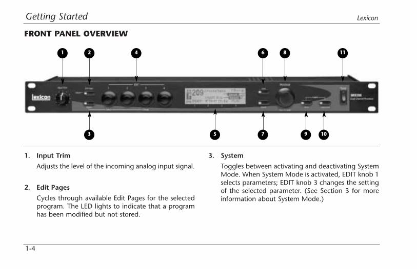
1. Input Trim
Adjusts the level of the incoming analog input signal.
2. Edit Pages
Cycles through available Edit Pages for the selectedprogram. The LED lights to indicate that a programhas been modified but not stored.
3. System
Toggles between activating and deactivating SystemMode. When System Mode is activated, EDIT knob 1selects parameters; EDIT knob 3 changes the settingof the selected parameter. (See Section 3 for moreinformation about System Mode.)
FRONT PANEL OVERVIEW
1 2
3
4 6 8 11
5 7 9 10

Getting StartedMPX 550
1-5
4. EDIT Knobs
Adjust parameters. Numbers 1 to 4 correspond tonumbers 1 to 4 beneath the front panel display.
5. Front Panel Display
Indicates information about the current program.(See page 1-6 for more information about the frontpanel display).
6. Load
Loads the selected program. The LED lights whenanother program is cued.
7. Bypass
Mutes or bypasses the incoming signal, dependingon the setting of the System Mode parameter BypassMode (see page 3-5).
8. PROGRAM
Scrolls through available programs and, whenpushed inward, program banks.
9. Store
Activates store functions. When pressed with Tap,enters MIDI Learn Mode (see page 6-2).
10. Tap/Cancel
Flashes to indicate tempo-based programs. Whenpressed twice, sets tempo. When held, uses inputlevel or dialed-in value to determine tempo. Whenpressed with Store, enters MIDI Learn Mode (seepage 6-2).
11. Power
Powers the unit on and off.

Getting Started Lexicon
1-6
1. Input Level Meters
Indicate incoming signal levels. Input level metersshow a minimum when the incoming signal is morethan -48dB digital full-scale. Level meters appear ininverse video when the signal approaches overload(-2dB digital full-scale). When signals are betweenthese extremes, the level meters appear as shownabove.
Input level meters show calibrated values, with 0dBindicating digital saturation. Markings on the openportion of each level meter show -6, -18, and -32dB.The meters have single-pixel precision in which eachpixel represents 2dB.
S/PDIF digital input sources that have been mastered“hot” (at the maximum bit rate) will cause the inputlevel meters to peak as if digital full-scale isoccurring. However, the unit is just receiving themaximum output from the source, which is loudenough to peak the meters. This is not a problem aslong as the source audio is not distorted.
Gain reduction from the compressor is indicated bya descending bar situated between the two inputlevel meters. It is also calibrated in 2dB incrementsper pixel.
2. Input/OVL Indicator
Reflects the input type in normal operation. The firstletter indicates input type, which is selected with theSystem Mode parameter Input Source (see page 3-4).
FRONT PANEL DISPLAY
3
1
2
9
4 7
5
6
8
Getting StartedMPX 550
1-7
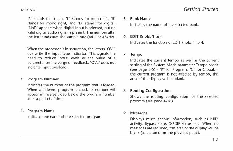
"S" stands for stereo, "L" stands for mono left, "R"stands for mono right, and "D" stands for digital."NoD" appears when digital input is selected, but novalid digital audio signal is present. The number afterthe letter indicates the sample rate (44.1 or 48kHz).
When the processor is in saturation, the letters "OVL"overwrite the input type indicator. This signals theneed to reduce input levels or the value of aparameter on the verge of feedback. "OVL" does notindicate input overload.
3. Program Number
Indicates the number of the program that is loaded.When a different program is cued, its number willappear in inverse video below the program numberafter a period of time.
4. Program Name
Indicates the name of the selected program.
5. Bank Name
Indicates the name of the selected bank.
6. EDIT Knobs 1 to 4
Indicates the function of EDIT knobs 1 to 4.
7. Tempo
Indicates the current tempo as well as the currentsetting of the System Mode parameter Tempo Mode(see page 3-5) - "P" for Program, "G" for Global. Ifthe current program is not affected by tempo, thisarea of the display will be blank.
8. Routing Configuration
Shows the routing configuration for the selectedprogram (see page 4-18).
9. Messages
Displays miscellaneous information, such as MIDIactivity, Bypass state, S/PDIF status, etc. When nomessages are required, this area of the display will beblank (as pictured on the previous page).

Getting Started Lexicon
1-8
1. AC Input Connector
Provides power to the unit with the supplied powercord.
2. MIDI IN and MIDI OUT/THRU
Two 5-pin DIN MIDI connectors are available forMIDI IN and software-selectable MIDI OUT/THRU.
3. FOOTSWITCH
Allows footswitch control of front panel Bypass andTap functions. A 1/4 inch Tip/Ring/Sleeve connectorand a momentary contact footswitch are available.(See page 1-10 for more information.)
REAR PANEL OVERVIEW
2 3 4
5
6
1
Tip
Ring
Sleeve
Tip Sleeve
Ring
Tap
Bypass

Getting StartedMPX 550
1-9
4. S/PDIF IN and OUT
Provide digital audio input and output. Two RCAS/PDIF connectors are available. The unit acceptsinputs at 44.1 or 48kHz.
5. ANALOG OUTPUTs
Provide analog audio output. Balanced outputs areavailable on either XLR or 1/4 inch Tip/Ring/Sleeveconnectors.
6. ANALOG INPUTs
Provide analog audio input. Balanced inputs areavailable on either XLR or 1/4 inch Tip/Ring/Sleeveconnectors.
Getting Started Lexicon
1-10
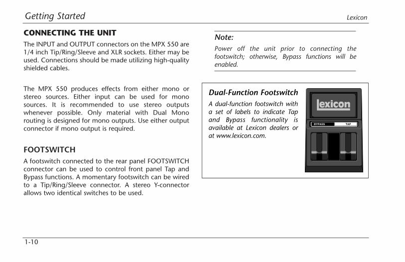
CONNECTING THE UNITThe INPUT and OUTPUT connectors on the MPX 550 are1/4 inch Tip/Ring/Sleeve and XLR sockets. Either may beused. Connections should be made utilizing high-qualityshielded cables.
The MPX 550 produces effects from either mono orstereo sources. Either input can be used for monosources. It is recommended to use stereo outputswhenever possible. Only material with Dual Monorouting is designed for mono outputs. Use either outputconnector if mono output is required.
FOOTSWITCHA footswitch connected to the rear panel FOOTSWITCHconnector can be used to control front panel Tap andBypass functions. A momentary footswitch can be wiredto a Tip/Ring/Sleeve connector. A stereo Y-connectorallows two identical switches to be used.
Note:Power off the unit prior to connecting thefootswitch; otherwise, Bypass functions will beenabled.
BYPASS TAP
Dual-Function FootswitchA dual-function footswitch witha set of labels to indicate Tapand Bypass functionality isavailable at Lexicon dealers orat www.lexicon.com.
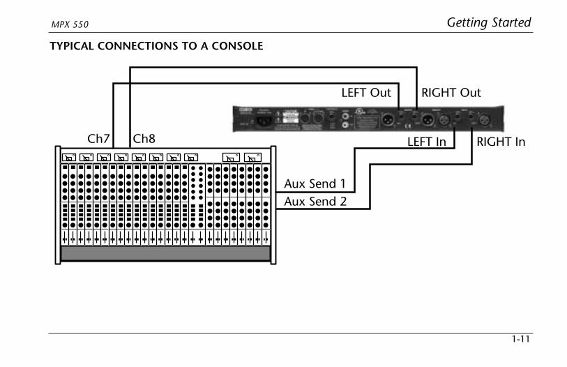
Ch7 Ch8
Aux Send 1Aux Send 2
RIGHT OutLEFT Out
RIGHT InLEFT In
Getting StartedMPX 550
1-11
TYPICAL CONNECTIONS TO A CONSOLE
Getting Started Lexicon
1-12
SETTING AUDIO LEVELS
Note:As with all audio products, it is good practice to firstpower on all outboard equipment, then the mixer,then the speakers.
INPUT1. Load Program 1.
2. Set the Mix parameter to Dry (Edit Page 1, EDITknob 4).
3. Using high-level program material, begin with a lowinput level and advance it slowly.
4. When audible distortion is reached or when thedisplay clip indicators light and remain lit, lower theinput level until the clip meters appear only on thehighest peaks.
The Input Trim knob allows the unit to be driven byan input level within a range of +8 to +20dBu. Theminimum setting (fully counterclockwise) should beoptimal for +4dBu (balanced) inputs. The maximumsetting (fully clockwise) should be optimal for-10dBV (unbalanced) inputs.
OUTPUT1. Press the front panel System button to activate
System Mode. Output Level, the first System Modeparameter, will be displayed.
2. Turn EDIT knob 3 to set the Output Level parameter.Unity gain for a +4dBu input device should be -12dB.
3. Press the System button again to deactivate SystemMode.

Basic Operation
2Selecting and Loading Programs . . . . . . . . . . . . . . . . . . . . . . . . . 2-2
Editing Programs . . . . . . . . . . . . . . . . . . . . . . . . . . . . . . . . . . . . 2-3
The “Adjust” Parameter. . . . . . . . . . . . . . . . . . . . . . . . . . . . . . . . 2-3
Storing Programs . . . . . . . . . . . . . . . . . . . . . . . . . . . . . . . . . . . . 2-4
The Compressor . . . . . . . . . . . . . . . . . . . . . . . . . . . . . . . . . . . . . 2-5
Tap Tempo . . . . . . . . . . . . . . . . . . . . . . . . . . . . . . . . . . . . . . . . . 2-6Matching Rhythm • Audio Tap • Global Tempo
Bypass . . . . . . . . . . . . . . . . . . . . . . . . . . . . . . . . . . . . . . . . . . . . 2-7

Basic Operation Lexicon
2-2
SELECTING AND LOADING PROGRAMSWhen powered on, the unit will load the last programthat was loaded during the previous operating session.To select another program, turn the front panelPROGRAM knob.
When the PROGRAM knob is turned clockwise, the unitwill cycle forward through programs in the selectedbank, then proceed to cycle forward through programsin the next bank. When turned counterclockwise, theunit will cycle backward through programs in theselected bank, then proceed to cycle backward throughprograms in the previous bank. When the PROGRAMknob is pushed inward and turned, the unit will cyclethrough program banks.
The name and number of the selected program appearon the front panel display (see page 1-6). TheLoad LED will light to indicate that the selectedprogram is cued for loading. After 4 seconds,the front panel display will revert to showing the nameand number of the loaded program. However, the LoadLED will remain lit to indicate that the selected programis still cued for loading. The number of the cued programwill appear in inverse video below the number of thecurrently loaded program. To load the cued program,press the front panel Load button.
The unit can be configured to automatically loadprograms 3/4 second after the PROGRAM knob stopsturning. To do this, set the System Mode parameter AutoLoad to Enabled (see page 3-7).
Turn the PROGRAM knob clockwise tocycle forward through all programs.
Turn the PROGRAM knob counterclockwise tocycle backward through all programs.
Press and turn the PROGRAM knob toselect a program bank.
Basic OperationMPX 550
2-3
EDITING PROGRAMSEach program features up to 20 parameters, which areorganized into Edit Pages with as many as four parameterseach. Press the front panel Edit Pages buttonto cycle through available Edit Pages for theloaded program.
Parameters available on the selected Edit Page appearacross the bottom of the front panel display, as shown onpage 1-6. The number below each parametercorresponds with the number above the Edit knob usedto change its setting. When a parameter setting ischanged, it will appear in inverse video on the frontpanel display and the Edit Pages LED will light to showthat the program has been modified. The LED will nolonger be lit when another program is loaded or if themodified version is stored.
If another program is selected before the modifiedprogram is stored, the edited version will still appear asthe loaded program. However, the Load LEDwill light to indicate that a new program is cuedfor loading.
THE "ADJUST" PARAMETERAn "Adjust" parameter has been customized forindividual programs, and in most cases controls severalparameters at once to handle complicated editingprocesses. For instance, "Adjust" controls the liveness ofspace in Chamber and Room programs by changingDecay, Early Reflections, and EQ simultaneously.
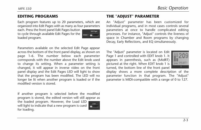
The "Adjust" parameter is located on EditPage 1 and controlled with EDIT knob 1. Itappears in parenthesis, such as (MidRT)pictured at the right. When EDIT knob 1 isturned, the bottom line of the front paneldisplay shows a more complete description of theparameter function in that program. The "Adjust"parameter is MIDI-compatible with a range of 0 to 127.

Basic Operation Lexicon
2-4
STORING PROGRAMSThe User Bank contains no programs when the MPX 550is shipped. However, it includes 64 memory locationsavailable for storing user-modified programs.
To store a program:
1. Press the Store button. The Store andTap/Cancel LEDs will light to indicate thatthe store function is armed. The first emptyUser Bank location will be selected.
To cancel the store function without savingthe program, press the Tap/Cancel button.This can be done at any time before thestore procedure is completed.
2. Use the PROGRAM knob to select a different UserBank location. The message area on the front paneldisplay (see page 1-6) indicates whether the selectedUser Bank location is available or empty.
3. The program appears on the front panel with itsoriginal name and a numeric suffix. If desired, useEDIT knobs 1 and 3 to change the name of theprogram.
4. Press the Store button to save the program to theselected location. The message "Stored" will appearbriefly on the display. The Edit LED will no longer belit when the saved version becomes the selectedprogram.
Note:When storing a user program, allow the unit tocomplete the entire store process before poweringthe unit off. If the unit is power cycled during theprocess, all previously stored programs may be lost.
Basic OperationMPX 550
2-5
THE COMPRESSORThe compressor is available in all programs, exceptDynamics. (Dynamics uses a different compressionmechanism, explained on page 4-33.) The compressorsits in the wet component of the signal in front of theeffects in the loaded program. It is controlled with fourparameters: CmpRatio, Threshld, CmpAttk, andCmpRels. These parameters are located on the last EditPage for each program, except those in the CmprssrBank.
The ratio (CmpRatio) parameter can be set to ratios of1:1 (off), 2:1, 3:1, 4:1, 5:1, and 10:1. The threshold(Threshld) parameter can be set within a 0 to -32dBrange. These settings are relative to 0dBFS (digitalsaturation). The compressor is disabled if either the ratioparameter is set to 1:1 or the threshold parameter is sethigh enough to prevent the incoming signal fromcrossing the compression threshold.
The attack (CmpAttk) and release (CmpRels) parametersdetermine how fast the compressor responds, within3dB of the output level dictated by the incoming signal.
For most music material, the release time should beabout four times longer than the attack time. Both mustbe long enough to accommodate the bass content of themusic.
If the compressor is set to react faster than the waveformof the music itself, the resulting changes in output levelwill re-shape the waveform enough to produceundesirable audio effects. For example, 80Hz has aperiod of 12ms. If this is a dominant component in themusic, set both the attack and release parameters to atleast 12ms, even higher for better results. Thecompressor acts on both the left and right channels atthe same time, using the sum of the two channels as itstrigger.
Compression presets are available in the Cmprssr Bank(see page 4-31). For other compression-only effects,send compressor output into a Dly/Eko program withthe Delay parameter set to 0. The compressor does notadd propagation delay to the audio path. (Note theconverters introduce about 2ms of propagation delay.)
Basic Operation Lexicon
2-6
TAP TEMPO
MATCHING RHYTHMTap Tempo can be used to match the delay times andmodulation rates of tempo-based programs with thoseof the music. The Tap/Cancel button LED will flashwhenever a tempo-based program is loaded. The currenttempo rate appears in the top-right corner of the frontpanel display.
It is not required to enter what "could be" thedelay time in milliseconds. Just press theTap/Cancel button twice, and the unit willcalculate the appropriate delay time. To change tempo,press the Tap/Cancel button twice again in the newrhythm.
Tempo can also be set with a footswitch (see page 1-10)or MIDI control device (see page 6-4).
AUDIO TAPTo use audio input to set tempo:
1. Press and hold the Tap/Cancel button until themessage "Detecting audio..." appears at the top ofthe front panel display. (The optional dual footswitchallows the musician to continue playing theinstrument while pressing and holding the Tapbutton.)
Tempo parameters available for the loaded programwill also appear on the front panel display.
2. Still holding the Tap/Cancel button, play two shortnotes in rhythm.
3. Release the Tap/Cancel button. The message "Knob3 to change" will appear at the top of the front paneldisplay to indicate that EDIT knob 3 is now availableto adjust tempo.

Basic OperationMPX 550
2-7
4. If desired, turn EDIT knob 3 to further adjust tempoin bpm (beats per minute).
5. Press the Tap/Cancel button to exit this mode.
Audio tap is a must for live performances. It offers asimple method of setting delay times and modulationrates to match the music.
GLOBAL TEMPOThe Tap/Cancel button LED will flash when a tempo-controlled program is loaded. Most factory presets arestored with individual tempo rates, which can becustomized to suit personal taste. Tap in the new tempo,then store the modified version of the program in theUser Bank.
To recall the tempo rate stored with each program, setthe System Mode parameter Tempo Mode (see page 3-5)to Program. The unit will apply the individual temposetting of each program as it is loaded. To apply thecurrent tempo rate to all programs, set the System Mode
parameter Tempo Mode to Global. The unit will ignoreindividual tempo settings and apply the current temposetting to each program as it is loaded.
BYPASSThe Bypass button can be used to force the unitto pass only dry audio, to mute the outputsimmediately, or to mute the inputs to theloaded program. Its function depends on the setting ofthe System Mode parameter Bypass Mode (see page 3-5).When Bypass Mode is set to Dry, the unit sends only dry,unprocessed audio to the outputs. When set to FullMute, the unit mutes the outputs. When set to InputMute, the unit mutes the inputs only. Running effectswill continue their natural decay.
Bypass functions can also be activated with a footswitch(see page 1-10) or MIDI control device (see page 6-4).
System Mode
3System Mode Functions . . . . . . . . . . . . . . . . . . . . . . . . . . . . . . . 3-2
Parameters • MIDI Dumps • Restore Default Commands
System Mode Lexicon
3-2
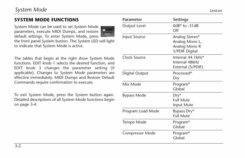
SYSTEM MODE FUNCTIONSSystem Mode can be used to set System Modeparameters, execute MIDI Dumps, and restoredefault settings. To enter System Mode, pressthe front panel System button. The System LED will lightto indicate that System Mode is active.
The tables that begin at the right show System Modefunctions. EDIT knob 1 selects the desired function, andEDIT knob 3 changes the parameter setting (ifapplicable). Changes to System Mode parameters areeffective immediately. MIDI Dumps and Restore DefaultCommands require confirmation to execute.
To exit System Mode, press the System button again.Detailed descriptions of all System Mode functions beginon page 3-4.
Parameter Settings
Output Level 0dB* to -31dBOff
Input Source Analog Stereo*Analog Mono L,Analog Mono RS/PDIF Digital
Clock Source Internal 44.1kHz*Internal 48kHzExternal (S/PDIF)
Digital Output Processed*Dry
Mix Mode Program*Global
Bypass Mode Dry*Full MuteInput Mute
Program Load Mode Bypass Dry*Full Mute
Tempo Mode Program*Global
Compressor Mode Program*Global
System ModeMPX 550
3-3
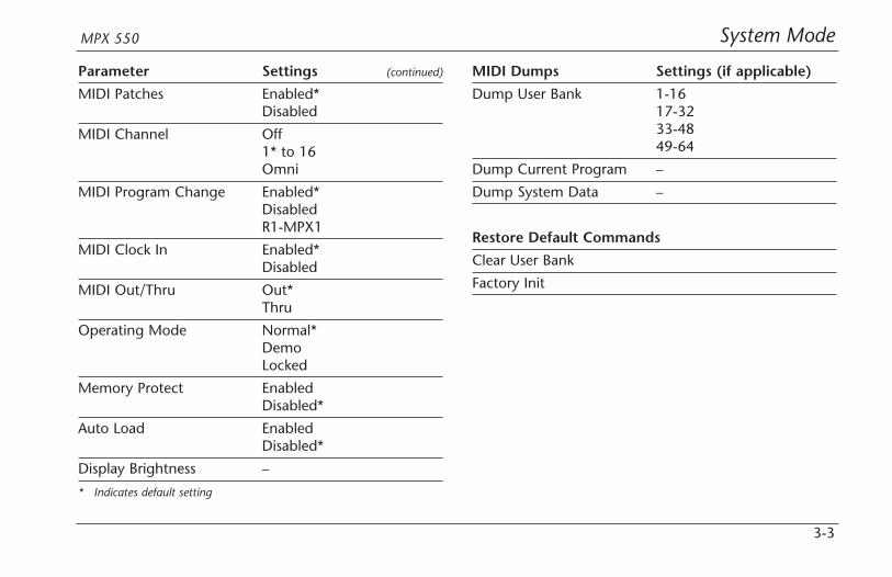
Parameter Settings (continued)
MIDI Patches Enabled*Disabled
MIDI Channel Off1* to 16Omni
MIDI Program Change Enabled*DisabledR1-MPX1
MIDI Clock In Enabled*Disabled
MIDI Out/Thru Out*Thru
Operating Mode Normal*DemoLocked
Memory Protect EnabledDisabled*
Auto Load EnabledDisabled*
Display Brightness –
* Indicates default setting
MIDI Dumps Settings (if applicable)
Dump User Bank 1-1617-3233-4849-64
Dump Current Program –
Dump System Data –
Restore Default Commands
Clear User Bank
Factory Init

System Mode Lexicon
3-4
PARAMETERS
Output Level (0 to -31dB, Off)
Sets output level attenuation within a 0 to -31dB range,or off.
Input Source
(Analog Stereo; Analog Mono L and R; S/PDIF Digital)
Selects input type. The current selection is indicated inthe lower-left corner of the front panel display. "S" standsfor Analog Stereo, "L" stands for Analog Mono L, "R"stands for Analog Mono R, and "D" stands for S/PDIFdigital. The number following the prefix indicates thesample rate (48 or 44.1kHz). "NoD" indicates that novalid digital audio signal is present.
When set to Analog Stereo, the unit processes signalsfrom both analog inputs. When set to Analog Mono L,the unit sends signals from the ANALOG INPUT labelledLEFT to both processor inputs. When set to Analog MonoR, the unit sends signals from the ANALOG INPUTlabelled RIGHT to both processor inputs.
When set to S/PDIF Digital, the unit processes signalsfrom the S/PDIF IN connector. If no valid digital audiosignal is present, the unit will mute and an alert messagewill appear on the front panel display.
Note:When the Input Source parameter is set to S/PDIFDigital, the Clock Source parameter willautomatically be set to External (S/PDIF).
Clock Source
(Internal 44.1kHz and 48kHz, External (S/PDIF))
Selects the internal or external clock source for the unit.When set to Internal 44.1kHz, the unit utilizes an internalclock with a 44.1kHz sample rate. When set to Internal48kHz, the unit utilizes an internal clock with a 48kHzsample rate. When set to External (S/PDIF), the unitutilizes the S/PDIF input signal, even if an analog sourceis used. "NoD" will appear in the lower-left corner of thefront panel display if no valid digital input signal ispresent to utilize for the external clock.

System ModeMPX 550
3-5
Digital Output (Processed, Dry)
Selects the source for the digital output. When set toProcessed, the digital output is the same as the analogoutputs. Its mix level will reflect the current setting of theMix parameter. When set to Dry, the digital output is theinput. This setting is useful for recording dry tracks whilestill providing processing at the analog outputs.
Mix Mode (Program, Global)
Controls the mix level that is applied when a newprogram is loaded. Mix levels are stored with eachprogram. When Mix Mode is set to Program, the unitapplies the stored mix level of the selected program tothat program as it is loaded. When set to Global, the unitignores stored mix levels and applies the current mixlevel to each program as it is loaded.
Bypass Mode (Dry, Full Mute, Input Mute)
Sets the function of Bypass. When set to Dry, the unitsends only dry, unprocessed audio to the outputs. Whenset to Full Mute, the unit mutes the outputs. When set toInput Mute, the unit mutes the inputs only. Runningeffects will continue their natural decay.
Program Load Mode (Bypass Dry, Full Mute)
Controls the processing of incoming audio signals duringprogram load. When set to Bypass Dry, the unit sendsonly dry, unprocessed audio to the outputs. When set toFull Mute, the unit mutes during program load.
Tempo Mode (Program, Global)
Controls the tempo setting that is applied when a newprogram is loaded. A tempo setting is stored with eachprogram. When Tempo Mode is set to Program, the unitapplies the stored tempo setting of each program as it isloaded. When set to Global, the unit applies the currenttempo setting to each program as it is loaded.
Compressor Mode (Program, Global)
Controls the compression settings that are applied whena new program is loaded. Compression settings arestored with each program. When Compressor Mode isset to Program, the unit applies the stored setting ofeach program as it is loaded. When set to Global, theunit applies the current compression setting to eachprogram as it is loaded.
System Mode Lexicon
3-6
MIDI Patches (Enabled, Disabled)
Enables and disables Learned Patches. When set toEnabled, the unit responds to Learned Patches. When setto Disabled, the unit ignores Learned Patches,preventing accidental changes.
MIDI Channel (Off, 1 to 16, Omni)
Selects the MIDI Channel for MPX 550 messages. Whenset to Off, the unit ignores messages sent on all MIDIchannels. When set within a range of 1 to 16, the unitresponds to messages sent on the selected MIDI channel.When set to Omni, the unit responds to messages senton all MIDI channels.
MIDI Program Change (Enabled, Disabled, R1-MPX 1)
Enables and disables MIDI Program Change messages.When set to Enabled, the unit responds to MIDI ProgramChange messages. When set to Disabled, the unitignores MIDI Program Change messages, preventingaccidental changes. When set to R1-MPX 1, the unitresponds to program change messages from a LexiconMPX R1 Foot Controller set to MPX 1 Mode.
MIDI Clock In (Enabled, Disabled)
Enables and disables MIDI Clock messages. When set toEnabled, Tap Tempo is changed by incoming MIDImessages. When set to Disabled, the unit ignores MIDIClock messages, preventing accidental changes.
MIDI Out/Thru (Out, Thru)
Controls the function of the MIDI OUT/THRU connector.When set to Out, the unit can generate its own MIDIDumps. When set to Thru, the unit can forward - butcannot generate or modify - MIDI messages.
Operating Mode (Normal, Demo, Locked)
Controls front panel knobs and buttons. When set toNormal, front panel controls perform their normalfunctions. When set to Demo, front panel controls areplaced in a continuous program load cycle fordemonstration purposes. When set to Locked, frontpanel controls are locked to their current settings. Whenfront panel controls are locked:

System ModeMPX 550
3-7
• The front panel PROGRAM knob is still available forselecting user programs only. Programs stored in theUser Bank are still available, but cannot be modified.
• The System Mode parameter Auto Load is set toEnabled.
• Bypass functions are still available.
• Tempo and Patches cannot be learned.
• System Mode can still be activated.
Changes to the Operating Mode parameter will not takeeffect until the unit has been powered off, then poweredon again.
Memory Protect (Enabled, Disabled)
Protects the User Bank from accidental changes. Whenset to Enabled, the unit prevents changes to the UserBank. However, it does not prevent changes to SystemMode parameters, nor does it prevent the restoration offactory-default settings. Restoring default settings willstill erase all programs stored in the User Bank. When setto Disabled, the unit does not prevent changes to theUser Bank.
Auto Load (Enabled, Disabled)
Determines whether the front panel Load button mustbe pressed to load selected programs. When set toEnabled, programs will automatically load 3/4 secondafter the PROGRAM knob stops turning. When set toDisabled, programs will not load until the Load button ispressed.
Display Brightness
Controls the brightness of the front panel display. TurnEDIT knob 3 clockwise to make the display darker, andcounterclockwise to make the display brighter.
System Mode Lexicon
3-8
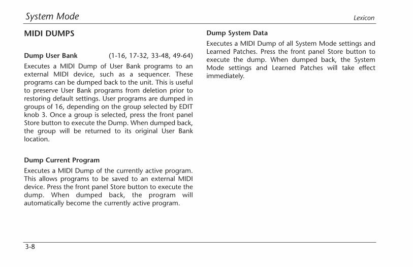
MIDI DUMPS
Dump User Bank (1-16, 17-32, 33-48, 49-64)
Executes a MIDI Dump of User Bank programs to anexternal MIDI device, such as a sequencer. Theseprograms can be dumped back to the unit. This is usefulto preserve User Bank programs from deletion prior torestoring default settings. User programs are dumped ingroups of 16, depending on the group selected by EDITknob 3. Once a group is selected, press the front panelStore button to execute the Dump. When dumped back,the group will be returned to its original User Banklocation.
Dump Current Program
Executes a MIDI Dump of the currently active program.This allows programs to be saved to an external MIDIdevice. Press the front panel Store button to execute thedump. When dumped back, the program willautomatically become the currently active program.
Dump System Data
Executes a MIDI Dump of all System Mode settings andLearned Patches. Press the front panel Store button toexecute the dump. When dumped back, the SystemMode settings and Learned Patches will take effectimmediately.

System ModeMPX 550
3-9
RESTORE DEFAULT COMMANDS
Clear User Bank
Arms a procedure to erase the contents of the User Bank.Press the front panel Store button to execute thisprocedure and return the User Bank to its factory-defaultcondition. This procedure cannot be executed when aUser program is running or when the System Modeparameter Memory Protect is set to Enabled.
Factory Init
Arms a procedure to restore parameters, System Modeparameters, User Bank programs, and Learned Patches totheir factory-default conditions. Press the front panelStore button to execute this procedure.

Program Descriptions
4Single Programs . . . . . . . . . . . . . . . . . . . . . . . . . . . . . . . . . . . . . 4-2
Plate • Gate/Inv • Hall • Chamber • Ambience • Room • Tremolo • Rotary •Chorus • Flange • Detune • Pitch • Dly/Eko
Special FX. . . . . . . . . . . . . . . . . . . . . . . . . . . . . . . . . . . . . . . . . 4-16Stereo Stage
Dual Programs . . . . . . . . . . . . . . . . . . . . . . . . . . . . . . . . . . . . . 4-18Efx Bal • Flng-Dly • Pch-Dly • Chor-Dly • Dly-Rvb • Flng-Rvb • Pch-Rvb •Chor-Rvb • MSplit Dly • MSplit Rvb • Dual Mono
Cmprssr . . . . . . . . . . . . . . . . . . . . . . . . . . . . . . . . . . . . . . . . . . 4-31
Dynamics . . . . . . . . . . . . . . . . . . . . . . . . . . . . . . . . . . . . . . . . . 4-32Peak Expansion • Compression • Tape Saturation • Level Meters • TypicalMastering Dynamics Control Adjustment
Live-FOH (Front of House) . . . . . . . . . . . . . . . . . . . . . . . . . . . . . 4-36

Program Descriptions Lexicon
4-2
SINGLE PROGRAMS
PLATEPlate reverb began with a large, thin sheet of metalsuspended upright under tension on springs.Transducers attached to the plate transmitted a signalthat made the plate vibrate, causing sounds broadcastthrough it to appear to be occurring in a large, openspace.
The Plate programs synthesize the sound of metal plateswith high initial diffusion and a relatively bright, coloredsound. These programs are designed to be heard as partof the music, mellowing and thickening the sound. Plateprograms are a popular choice for enhancing pop music,particularly percussion.
Plate Programs "Adjust" Tap
1 Small Plate (Livenes) –
2 Medium Plate (Livenes) –
3 Large Plate (Livenes) –
4 Tap PreDelay (MidRT) PreDelay(1/32 Note)
5 Tape Slap (ips) –
6 Rich Plate (MidRT) –
7 Large&Bright (MidRT) –
8 VocalPlate (Livenes) Echo
9 Drum Plate (Livenes) –
Program DescriptionsMPX 550
4-3
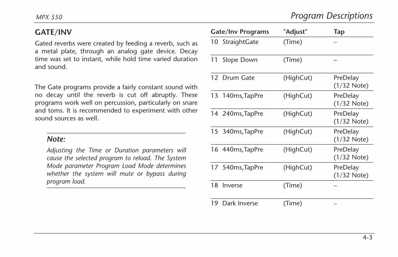
GATE/INVGated reverbs were created by feeding a reverb, such asa metal plate, through an analog gate device. Decaytime was set to instant, while hold time varied durationand sound.
The Gate programs provide a fairly constant sound withno decay until the reverb is cut off abruptly. Theseprograms work well on percussion, particularly on snareand toms. It is recommended to experiment with othersound sources as well.
Note:Adjusting the Time or Duration parameters willcause the selected program to reload. The SystemMode parameter Program Load Mode determineswhether the system will mute or bypass duringprogram load.
Gate/Inv Programs "Adjust" Tap
10 StraightGate (Time) –
11 Slope Down (Time) –
12 Drum Gate (HighCut) PreDelay(1/32 Note)
13 140ms,TapPre (HighCut) PreDelay(1/32 Note)
14 240ms,TapPre (HighCut) PreDelay(1/32 Note)
15 340ms,TapPre (HighCut) PreDelay(1/32 Note)
16 440ms,TapPre (HighCut) PreDelay(1/32 Note)
17 540ms,TapPre (HighCut) PreDelay(1/32 Note)
18 Inverse (Time) –
19 Dark Inverse (Time) –

Program Descriptions Lexicon
4-4
HALLLexicon’s Hall programs recreate the acoustics of actualplaces - from grand, reverberant enclosures to smallconcert halls.
The clean reverberation of Hall programs is designed toadd spaciousness without altering source material. Inaddition to general instrumental and vocal applications,the Hall programs give separately recorded tracks a senseof belonging to the same performance.
Hall Programs "Adjust" Tap
20 Small Hall (MidRT) –
21 Medium Hall (MidRT) –
22 Large Hall (MidRT) –
23 Small Church (MidRT) –
24 Large Church (MidRT) –
25 Jazz Hall (MidRT) –
26 Dance Hall (MidRT) –
27 Synth Hall (MidRT) –
28 Concert Hall (MidRT) –
29 Gothic Hall (MidRT) –

Program DescriptionsMPX 550
4-5
CHAMBERHistorically, recording studio chambers were oddlyshaped rooms with a loudspeaker and set ofmicrophones to collect ambience in various parts of theroom.
Stereo Chamber programs produce even, relativelydimensionless reverberation with little color change assound decays. The initial diffusion is similar to Hallprograms. However, the sense of size and space is muchless obvious. This characteristic, coupled with the lowcolor of the decay tail, makes these programs useful ona wide range of material - especially the spoken voice.Chamber programs give the spoken voice a noticeableincrease in loudness with low color.
Chamber Programs "Adjust" Tap
30 Brick Wall (HighCut) –
31 Basement (HighCut) –
32 LiveConcert (Livenes) Eko Delay
33 Drum Chamber (MidRT) –
34 Moves on . . . (Livenes) –
35 Live Chamber (Livenes) –
36 VocalChambr1 (Livenes) Eko Delay
37 VocalChambr2 (Livenes) Eko Delay
38 WideChamber (Livenes)
39 PCM60: Large (MidRT)
Program Descriptions Lexicon
4-6
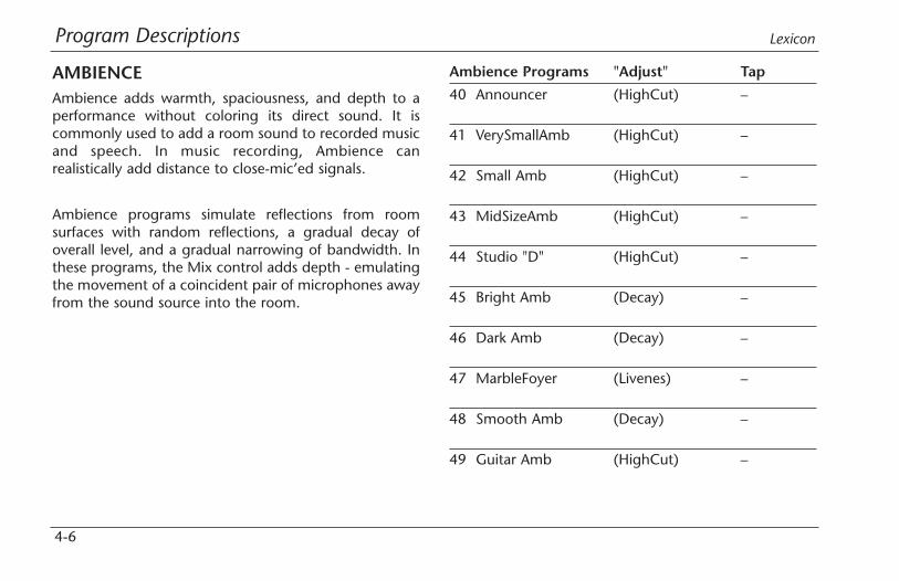
AMBIENCEAmbience adds warmth, spaciousness, and depth to aperformance without coloring its direct sound. It iscommonly used to add a room sound to recorded musicand speech. In music recording, Ambience canrealistically add distance to close-mic’ed signals.
Ambience programs simulate reflections from roomsurfaces with random reflections, a gradual decay ofoverall level, and a gradual narrowing of bandwidth. Inthese programs, the Mix control adds depth - emulatingthe movement of a coincident pair of microphones awayfrom the sound source into the room.
Ambience Programs "Adjust" Tap
40 Announcer (HighCut) –
41 VerySmallAmb (HighCut) –
42 Small Amb (HighCut) –
43 MidSizeAmb (HighCut) –
44 Studio "D" (HighCut) –
45 Bright Amb (Decay) –
46 Dark Amb (Decay) –
47 MarbleFoyer (Livenes) –
48 Smooth Amb (Decay) –
49 Guitar Amb (HighCut) –

Program DescriptionsMPX 550
4-7
ROOMRoom programs simulate actual rooms where there is astrong sense of being in a small, live place. Theseprograms are useful on drums and percussion, and canalso be applied to electric guitar tracks.
Room Programs "Adjust" Tap
50 Bedroom (Walls) –
51 Tiled Room (LFBoost) –
52 Studio "C" (MidRT) –
53 Small Room (Livenes) –
54 Studio "B" (MidRT) –
55 Rehearsal Rm (EQ) –
56 Studio "A" (MidRT) –
57 Large Room (EQ) –
58 Fat Space (MidRT) –
59 Chunky Space (EQ) –
Program Descriptions Lexicon
4-8
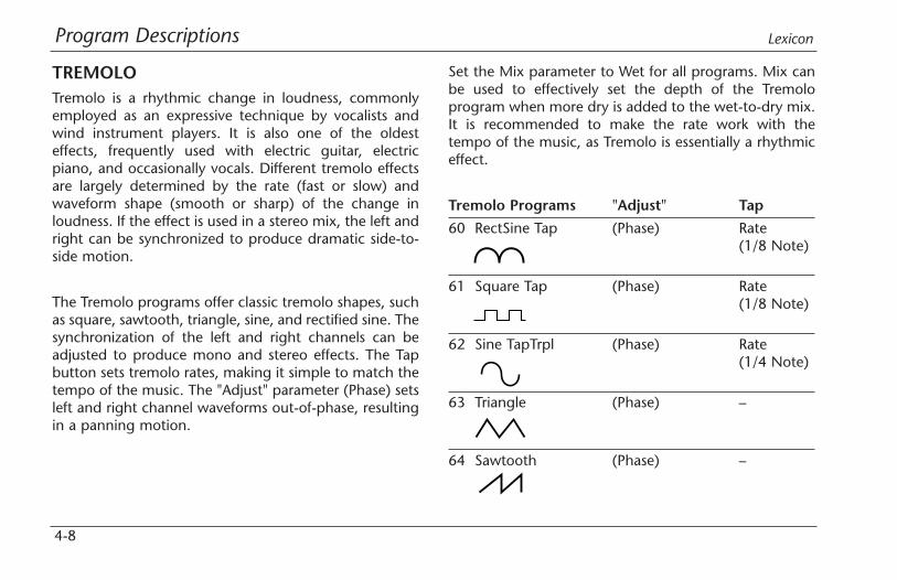
TREMOLOTremolo is a rhythmic change in loudness, commonlyemployed as an expressive technique by vocalists andwind instrument players. It is also one of the oldesteffects, frequently used with electric guitar, electricpiano, and occasionally vocals. Different tremolo effectsare largely determined by the rate (fast or slow) andwaveform shape (smooth or sharp) of the change inloudness. If the effect is used in a stereo mix, the left andright can be synchronized to produce dramatic side-to-side motion.
The Tremolo programs offer classic tremolo shapes, suchas square, sawtooth, triangle, sine, and rectified sine. Thesynchronization of the left and right channels can beadjusted to produce mono and stereo effects. The Tapbutton sets tremolo rates, making it simple to match thetempo of the music. The "Adjust" parameter (Phase) setsleft and right channel waveforms out-of-phase, resultingin a panning motion.
Set the Mix parameter to Wet for all programs. Mix canbe used to effectively set the depth of the Tremoloprogram when more dry is added to the wet-to-dry mix.It is recommended to make the rate work with thetempo of the music, as Tremolo is essentially a rhythmiceffect.
Tremolo Programs "Adjust" Tap
60 RectSine Tap (Phase) Rate(1/8 Note)
61 Square Tap (Phase) Rate(1/8 Note)
62 Sine TapTrpl (Phase) Rate(1/4 Note)
63 Triangle (Phase) –
64 Sawtooth (Phase) –
Program DescriptionsMPX 550
4-9
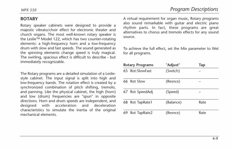
ROTARYRotary speaker cabinets were designed to provide amajestic vibrato/choir effect for electronic theater andchurch organs. The most well-known rotary speaker isthe Leslie™ Model 122, which has two counter-rotatingelements: a high-frequency horn and a low-frequencydrum with slow and fast speeds. The sound generated asthe spinning elements change speed is truly magical.The swirling, spacious effect is difficult to describe - butimmediately recognizable.
The Rotary programs are a detailed simulation of a Leslie-style cabinet. The input signal is split into high andlow-frequency bands. The rotation effect is created by asynchronized combination of pitch shifting, tremolo,and panning. Like the physical cabinet, the high (horn)and low (drum) frequencies are "spun" in oppositedirections. Horn and drum speeds are independent, anddesigned with acceleration and decelerationcharacteristics to simulate the inertia of the originalmechanical elements.
A virtual requirement for organ music, Rotary programsalso sound remarkable with guitar and electric pianorhythm parts. In fact, these programs are greatalternatives to chorus and tremolo effects for any soundsource.
To achieve the full effect, set the Mix parameter to Wetfor all programs.
Rotary Programs "Adjust" Tap
65 Rot:SlowFast (Switch) –
66 Rot Slow (Resnce) –
67 Rot SpeedAdj (Speed) –
68 Rot TapRate1 (Balance) Rate
69 Rot TapRate2 (Resnce) Rate
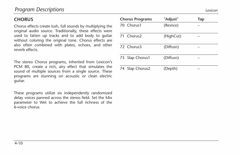
Program Descriptions Lexicon
4-10
CHORUSChorus effects create lush, full sounds by multiplying theoriginal audio source. Traditionally, these effects wereused to fatten up tracks and to add body to guitarwithout coloring the original tone. Chorus effects arealso often combined with plates, echoes, and otherreverb effects.
The stereo Chorus programs, inherited from Lexicon’sPCM 80, create a rich, airy effect that simulates thesound of multiple sources from a single source. Theseprograms are stunning on acoustic or clean electricguitar.
These programs utilize six independently randomizeddelay voices panned across the stereo field. Set the Mixparameter to Wet to achieve the full richness of the6-voice chorus.
Chorus Programs "Adjust" Tap
70 Chorus1 (Resnce) –
71 Chorus2 (HighCut) –
72 Chorus3 (Diffusn) –
73 Slap Chorus1 (Diffusn) –
74 Slap Chorus2 (Depth) –
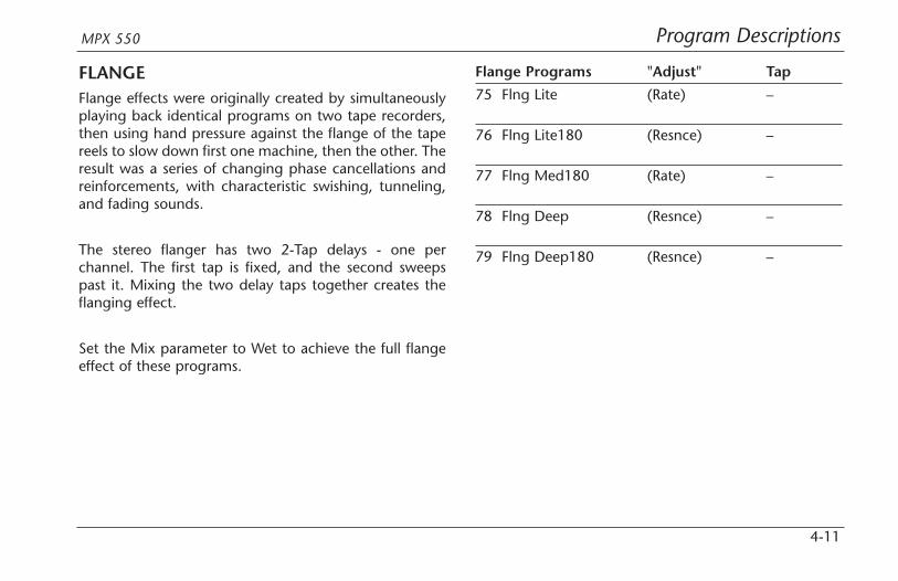
Program DescriptionsMPX 550
4-11
FLANGEFlange effects were originally created by simultaneouslyplaying back identical programs on two tape recorders,then using hand pressure against the flange of the tapereels to slow down first one machine, then the other. Theresult was a series of changing phase cancellations andreinforcements, with characteristic swishing, tunneling,and fading sounds.
The stereo flanger has two 2-Tap delays - one perchannel. The first tap is fixed, and the second sweepspast it. Mixing the two delay taps together creates theflanging effect.
Set the Mix parameter to Wet to achieve the full flangeeffect of these programs.
Flange Programs "Adjust" Tap
75 Flng Lite (Rate) –
76 Flng Lite180 (Resnce) –
77 Flng Med180 (Rate) –
78 Flng Deep (Resnce) –
79 Flng Deep180 (Resnce) –

Program Descriptions Lexicon
4-12
DETUNEDetune effects create delayed and pitch-shifted versionsof the original source, thickening the sound. This createsa particularly effective simulation of double-tracking.These effects are also great alternatives to Chorus effects,adding the richness of a chorus without the audiblesweep caused by the chorus rate.
The 4-voice stereo Detune programs have one pair ofvoices per channel. As more detune is applied with the"Adjust" parameter, the pair become more out of tune,providing a lush sound without the need for mixing in adry signal.
Set the Mix parameter to Wet to achieve the full effect ofthese programs.
Detune Programs "Adjust" Tap
80 Detune Mild (Dtuning) –
81 Detune (Dtuning) –Med&Warm
82 Detune Heavy (Dtuning) –
83 Det Xtreme (Dtuning) –
84 Pitch Detune (Dtuning) –

Program DescriptionsMPX 550
4-13
PITCHAltering the pitch of a sound produces a wide range ofeffects - from subtle detuning, to harmonies, to chords.The stereo polyphonic Pitch programs can be used toshift program material or monophonic sources within arange of one octave up to two octaves down.
For pitch correction, set the Mix parameter to Wet. Forharmonization, set the Mix parameter to the desiredsetting.
Pitch Programs "Adjust" Tap
85 Pch Chrmatic (Pitch) –
86 Pitch Fine (Pitch) –
87 Pch 4th-5ths (Pitch) –
88 Pch PowerInv (Inversn) –
89 Vocal Chorus (HighCut) –
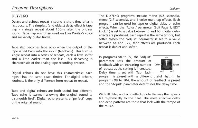
Program Descriptions Lexicon
4-14
DLY/EKODelays and echoes repeat a sound a short time after itfirst occurs. The simplest (and oldest) delay effect is tapeslap - a single repeat about 100ms after the originalsound. Tape slap was often used on Elvis Presley’s voiceand rockabilly guitar tracks.
Tape slap becomes tape echo when the output of thetape is fed back into the input (feedback). This turns asingle repeat into a series of repeats, each a little softerand a little darker than the last. This darkening ischaracteristic of the analog tape recording process.
Digital echoes do not have this characteristic; eachrepeat has the same exact timbre. For digital echoes,loudness is the only difference from repeat to repeat.
Tape and digital echoes are both useful, but different.Tape echo is warmer, allowing the original sound todistinguish itself. Digital echo presents a "perfect" copyof the original sound.
The DLY/EKO programs include mono (5.5 seconds),stereo (2.7 seconds), and 6-voice multi-tap effects. Eachprogram can be used for tape or digital delay or echoeffects. When the "Adjust" parameter (Edit Page 1, EDITknob 1) is set to a value between 0 and 63, digital delayeffects are produced. Each repeat is the same timbre, butsofter. When the "Adjust" parameter is set to a valuebetween 64 and 127, tape effects are produced. Eachrepeat is darker and softer.
In programs 90 to 97, the "Adjust"parameter sets the amount offeedback with an increasing numberof repeats as the setting is increased.Delay time is set with Tap. Eachprogram is preset with a different useful rhythm. Inprograms 98 to 104, the amount of feedback is presetand the "Adjust" parameter determines the delay time.
With all delay and echo effects, note the way the repeatsfall rhythmically to the beat. The most effective delayand echo patterns are those that lock with the tempo ofthe music.
MAX
MIN
MAX
EchoesDelays
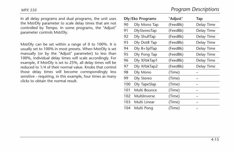
Program DescriptionsMPX 550
4-15
In all delay programs and dual programs, the unit usesthe MstrDly parameter to scale delay times that are notcontrolled by Tempo. In some programs, the "Adjust"parameter controls MstrDly.
MstrDly can be set within a range of 0 to 100%. It isusually set to 100% in most presets. When MstrDly is setmanually (or by the "Adjust" parameter) to less than100%, individual delay times will scale accordingly. Forexample, if MstrDly is set to 25%, all delay times will bereduced to 1/4 of their normal value. Knobs that controlthose delay times will become correspondingly lesssensitive - requiring, in this example, four times as manyclicks to obtain the normal result.
Dly/Eko Programs "Adjust" Tap
90 Dly Mono Tap (FeedBk) Delay Time
91 DlyStereoTap (FeedBk) Delay Time
92 Dly ShuflTap (FeedBk) Delay Time
93 Dly Dot8 Tap (FeedBk) Delay Time
94 Dly 8+3plTap (FeedBk) Delay Time
95 Dly Pong Tap (FeedBk) Delay Time
96 Dly XFbkTap1 (FeedBk) Delay Time
97 Dly XFbkTap2 (FeedBk) Delay Time
98 Dly Mono (Time) –
99 Dly Stereo (Time) –
100 Dly TapeSlap (Time) –
101 Multi Bounce (Time) –
102 MultiInverse (Time) –
103 Multi Linear (Time) –
104 Multi Pong (Time) –
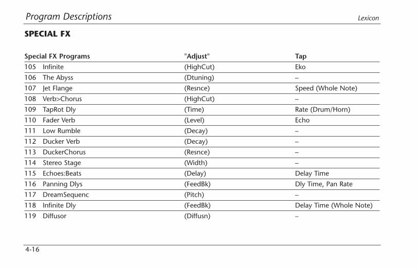
Program Descriptions Lexicon
4-16
SPECIAL FX
Special FX Programs "Adjust" Tap
105 Infinite (HighCut) Eko
106 The Abyss (Dtuning) –
107 Jet Flange (Resnce) Speed (Whole Note)
108 Verb>Chorus (HighCut) –
109 TapRot Dly (Time) Rate (Drum/Horn)
110 Fader Verb (Level) Echo
111 Low Rumble (Decay) –
112 Ducker Verb (Decay) –
113 DuckerChorus (Resnce) –
114 Stereo Stage (Width) –
115 Echoes:Beats (Delay) Delay Time
116 Panning Dlys (FeedBk) Dly Time, Pan Rate
117 DreamSequenc (Pitch) –
118 Infinite Dly (FeedBk) Delay Time (Whole Note)
119 Diffusor (Diffusn) –
Program DescriptionsMPX 550
4-17
STEREO STAGEStereo Stage provides stereo reverb while preserving thedry signal. To use this program, note the following:
• Use the MPX 550 in line between the mixer andhouse amplifiers - not as an effect mixed back intothe main left and right channels on the mixer.
• Pan the input channels on the mixer fully to eachmusician’s side of the stage.
• Keep the Mix parameter set to 50% (the defaultProgram Load Mode setting).
• Adjust reverb level by setting the Efx Bal parameterbetween 100:0% (full left) and 60:40%.
• The ideal setting for the Width parameter dependson the distance between the speakers at each side ofthe stage. The program loads with an assumedspacing of about 20 feet, with an adjustment rangeof 10 to 50 feet. The width setting assumes thatmost audience members are seated within about 30degrees to either side of the stage centerline. Ifaudience members are seated further to the sides ofthe stage, the setting can be increased. Otherwise, itshould be kept as low as possible.
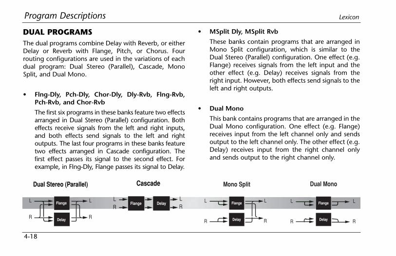
Program Descriptions Lexicon
4-18
DUAL PROGRAMSThe dual programs combine Delay with Reverb, or eitherDelay or Reverb with Flange, Pitch, or Chorus. Fourrouting configurations are used in the variations of eachdual program: Dual Stereo (Parallel), Cascade, MonoSplit, and Dual Mono.
• Flng-Dly, Pch-Dly, Chor-Dly, Dly-Rvb, Flng-Rvb,Pch-Rvb, and Chor-Rvb
The first six programs in these banks feature two effectsarranged in Dual Stereo (Parallel) configuration. Botheffects receive signals from the left and right inputs,and both effects send signals to the left and rightoutputs. The last four programs in these banks featuretwo effects arranged in Cascade configuration. Thefirst effect passes its signal to the second effect. Forexample, in Flng-Dly, Flange passes its signal to Delay.
• MSplit Dly, MSplit Rvb
These banks contain programs that are arranged inMono Split configuration, which is similar to theDual Stereo (Parallel) configuration. One effect (e.g.Flange) receives signals from the left input and theother effect (e.g. Delay) receives signals from theright input. However, both effects send signals to theleft and right outputs.
• Dual Mono
This bank contains programs that are arranged in theDual Mono configuration. One effect (e.g. Flange)receives input from the left channel only and sendsoutput to the left channel only. The other effect (e.g.Delay) receives input from the right channel onlyand sends output to the right channel only.
Dual Stereo (Parallel)
Flange
Delay
L
R
L
R
Mono Split
Flange
Delay
L
R
L
R
Dual Mono
Flange
Delay
L
R
L
R
Cascade
Flange DelayLR
LR

Program DescriptionsMPX 550
4-19
EFX BALThe Efx Bal parameter controls the relative balance ofeach effect in the dual programs. In Cascade variations,the parameter also varies the amount of the first effect ordry signal fed into the second effect.
The illustration below uses the Pch-Dly program to showthe effect of the Efx Bal parameter at certain settingswhen a Cascade variation is selected.
Pitch Delay
Pitch Delay Pitch Delay
Pitch DelayDelayPitch
50:50%: Provides delayed pitch shift.
100:0%: Provides pitch shift. 0:100%: Provides delayed dry signal.
75:25%:Provides pitch shift, plus delayed pitch shift.
25:75%:Provides delayed pitch shift, plus delayed dry signal.

Program Descriptions Lexicon
4-20
FLNG-DLY
Flng-Dly Programs "Adjust" Tap Routing
120 Flng Tap (FeedBk) Delay Time (1/4 Note) Dual Stereo (Parallel)
121 Flng .8Tap (FeedBk) Dotted (1/8 Note) Dual Stereo (Parallel)
122 Flng 3plTap (FeedBk) Triplet (1/8 Note) Dual Stereo (Parallel)
123 Flng PongTap (FeedBk) Delay Time (1/4 Note) Dual Stereo (Parallel)
124 Flng Xfeed (Time) – Dual Stereo (Parallel)
125 Flng Bounce (Time) – Dual Stereo (Parallel)
126 Flng > Tap (FeedBk) Delay Time (1/4 Note) Cascade
127 Flng > Fbk (Time) – Cascade
128 Flng > Pong (FeedBk) Delay Time (1/4 Note) Cascade
129 Flng > Bnce (Time) – Cascade
Dual Stereo (Parallel)
Flange
Delay
L
R
L
R
Cascade
Flange DelayLR
LR
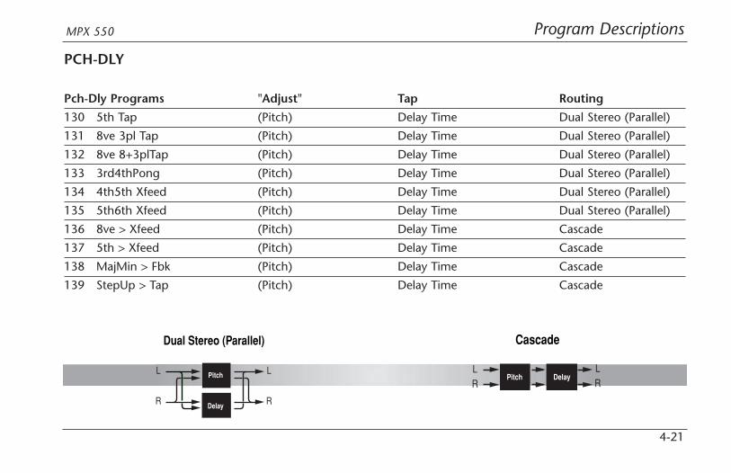
Program DescriptionsMPX 550
4-21
PCH-DLY
Pch-Dly Programs "Adjust" Tap Routing
130 5th Tap (Pitch) Delay Time Dual Stereo (Parallel)
131 8ve 3pl Tap (Pitch) Delay Time Dual Stereo (Parallel)
132 8ve 8+3plTap (Pitch) Delay Time Dual Stereo (Parallel)
133 3rd4thPong (Pitch) Delay Time Dual Stereo (Parallel)
134 4th5th Xfeed (Pitch) Delay Time Dual Stereo (Parallel)
135 5th6th Xfeed (Pitch) Delay Time Dual Stereo (Parallel)
136 8ve > Xfeed (Pitch) Delay Time Cascade
137 5th > Xfeed (Pitch) Delay Time Cascade
138 MajMin > Fbk (Pitch) Delay Time Cascade
139 StepUp > Tap (Pitch) Delay Time Cascade
Dual Stereo (Parallel)
Pitch
Delay
L
R
L
R
Cascade
Pitch DelayLR
LR

Program Descriptions Lexicon
4-22
CHOR-DLY
Chor-Dly Programs "Adjust" Tap Routing
140 Chor Tap (FeedBk) Delay Time Dual Stereo (Parallel)
141 Chor .8Tap (FeedBk) Delay Time Dual Stereo (Parallel)
142 Chor 8+3pl (FeedBk) Delay Time Dual Stereo (Parallel)
143 Chor Pong (FeedBk) Delay Time Dual Stereo (Parallel)
144 Chor Repeat (Time) – Dual Stereo (Parallel)
145 Chor Bounce (Time) – Dual Stereo (Parallel)
146 Chor > Tap (FeedBk) Delay Time Cascade
147 Chor >Repeat (Time) – Cascade
148 Chor > Pong (FeedBk) Delay Time Cascade
149 Chor > Bnce (Time) – Cascade
Dual Stereo (Parallel)
Chorus
Delay
L
R
L
R
Cascade
Chorus DelayLR
LR
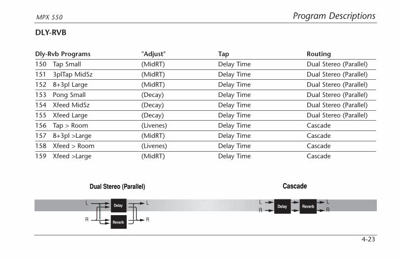
Program DescriptionsMPX 550
4-23
DLY-RVB
Dly-Rvb Programs "Adjust" Tap Routing
150 Tap Small (MidRT) Delay Time Dual Stereo (Parallel)
151 3plTap MidSz (MidRT) Delay Time Dual Stereo (Parallel)
152 8+3pl Large (MidRT) Delay Time Dual Stereo (Parallel)
153 Pong Small (Decay) Delay Time Dual Stereo (Parallel)
154 Xfeed MidSz (Decay) Delay Time Dual Stereo (Parallel)
155 Xfeed Large (Decay) Delay Time Dual Stereo (Parallel)
156 Tap > Room (Livenes) Delay Time Cascade
157 8+3pl >Large (MidRT) Delay Time Cascade
158 Xfeed > Room (Livenes) Delay Time Cascade
159 Xfeed >Large (MidRT) Delay Time Cascade
Dual Stereo (Parallel)
Delay
Reverb
L
R
L
R
Cascade
Delay ReverbLR
LR
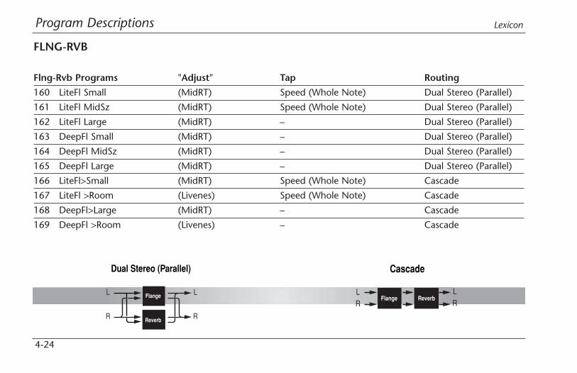
Program Descriptions Lexicon
4-24
FLNG-RVB
Flng-Rvb Programs "Adjust" Tap Routing
160 LiteFl Small (MidRT) Speed (Whole Note) Dual Stereo (Parallel)
161 LiteFl MidSz (MidRT) Speed (Whole Note) Dual Stereo (Parallel)
162 LiteFl Large (MidRT) – Dual Stereo (Parallel)
163 DeepFl Small (MidRT) – Dual Stereo (Parallel)
164 DeepFl MidSz (MidRT) – Dual Stereo (Parallel)
165 DeepFl Large (MidRT) – Dual Stereo (Parallel)
166 LiteFl>Small (MidRT) Speed (Whole Note) Cascade
167 LiteFl >Room (Livenes) Speed (Whole Note) Cascade
168 DeepFl>Large (MidRT) – Cascade
169 DeepFl >Room (Livenes) – Cascade
Dual Stereo (Parallel)
Flange
Reverb
L
R
L
R
Cascade
Flange ReverbLR
LR

Program DescriptionsMPX 550
4-25
PCH-RVB
Pch-Rvb Programs "Adjust" Tap Routing
170 3rd4th Room (Pitch) – Dual Stereo (Parallel)
171 4th5th Room (Pitch) – Dual Stereo (Parallel)
172 5th6th Room (Pitch) – Dual Stereo (Parallel)
173 8ve MidSiz (Pitch) – Dual Stereo (Parallel)
174 Power MidSiz (MidRT) – Dual Stereo (Parallel)
175 Detune Room (Dtuning) – Dual Stereo (Parallel)
176 Fine > Small (Pitch) – Cascade
177 Power >Large (MidRT) – Cascade
178 4th > MidSiz (MidRT) – Cascade
179 8ve > MidSz (MidRT) – Cascade
Dual Stereo (Parallel)
Pitch
Reverb
L
R
L
R
Cascade
Pitch ReverbLR
LR
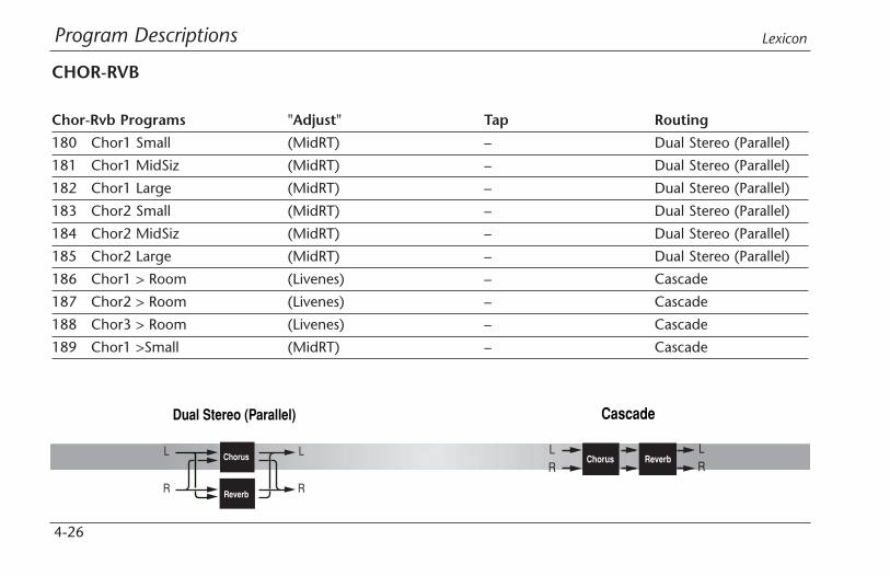
Program Descriptions Lexicon
4-26
CHOR-RVB
Chor-Rvb Programs "Adjust" Tap Routing
180 Chor1 Small (MidRT) – Dual Stereo (Parallel)
181 Chor1 MidSiz (MidRT) – Dual Stereo (Parallel)
182 Chor1 Large (MidRT) – Dual Stereo (Parallel)
183 Chor2 Small (MidRT) – Dual Stereo (Parallel)
184 Chor2 MidSiz (MidRT) – Dual Stereo (Parallel)
185 Chor2 Large (MidRT) – Dual Stereo (Parallel)
186 Chor1 > Room (Livenes) – Cascade
187 Chor2 > Room (Livenes) – Cascade
188 Chor3 > Room (Livenes) – Cascade
189 Chor1 >Small (MidRT) – Cascade
Dual Stereo (Parallel)
Chorus
Reverb
L
R
L
R
Cascade
Chorus ReverbLR
LR

Program DescriptionsMPX 550
4-27
MSPLIT DLY
MSplit Dly Programs "Adjust" Tap Routing
190 Flng + Tap (FeedBk) 1/4 Note Mono Split
191 Flng + Pong (FeedBk) 1/4 Note Mono Split
192 Flng + Xfeed (Time) – Mono Split
193 Flng + Bnce (Time) – Mono Split
194 DeepFl + Dly (Time) – Mono Split
195 5th + Tap (Pitch) Delay Time Mono Split
196 8ve + 3plTap (Pitch) Delay Time Mono Split
197 4th5th+Xfeed (Pitch) Delay Time Mono Split
198 5th6th+Xfeed (Pitch) Delay Time Mono Split
199 PchFine +Tap (Pitch) Delay Time Mono Split
200 Chor + Tap (FeedBk) Delay Time Mono Split
201 Chor + Pong (FeedBk) Delay Time Mono Split
202 Chor + Xfeed (Time) – Mono Split
203 Chor + Bnce (Time) – Mono Split
204 Chor+Inverse (Time) – Mono SplitNote: The Mono Split routing configuration is illustrated on page 4-18.

Program Descriptions Lexicon
4-28
MSPLIT RVB
MSplit Rvb Programs "Adjust" Tap Routing
205 Tap + MidSiz (MidRT) Delay Time Mono Split
206 Pong + Large (MidRT) Delay Time Mono Split
207 Bnce + MidSz (MidRT) Delay Time Mono Split
208 Xfeed + Small (MidRT) Delay Time Mono Split
209 Xfeed+MidSiz (MidRT) Delay Time Mono Split
210 LiteFl+MidSz (MidRT) – Mono Split
211 LiteFl+Large (MidRT) – Mono Split
212 DeepFl+Small (MidRT) – Mono Split
213 DeepFl+MidSz (MidRT) – Mono Split
214 DeepFl +Room (Livenes) – Mono Split
215 4th5th +Room (Pitch) – Mono Split
216 5th6th +Room (Pitch) – Mono Split
217 4ths + Large (MidRT) – Mono Split
218 8ve + MidSz (MidRT) – Mono Split
219 PchFin+MidSz (Pitch) – Mono Split
220 Chor1 +Small (MidRT) – Mono Split

Program DescriptionsMPX 550
4-29
MSplit Rvb Programs "Adjust" Tap Routing
221 Chor1+ Large (MidRT) – Mono Split
222 Chor2+MidSiz (MidRT) – Mono Split
223 Chor2+ Large (MidRT) – Mono Split
224 Chor3+MidSiz (MidRT) – Mono SplitNote: The Mono Split routing configuration is illustrated on page 4-18.
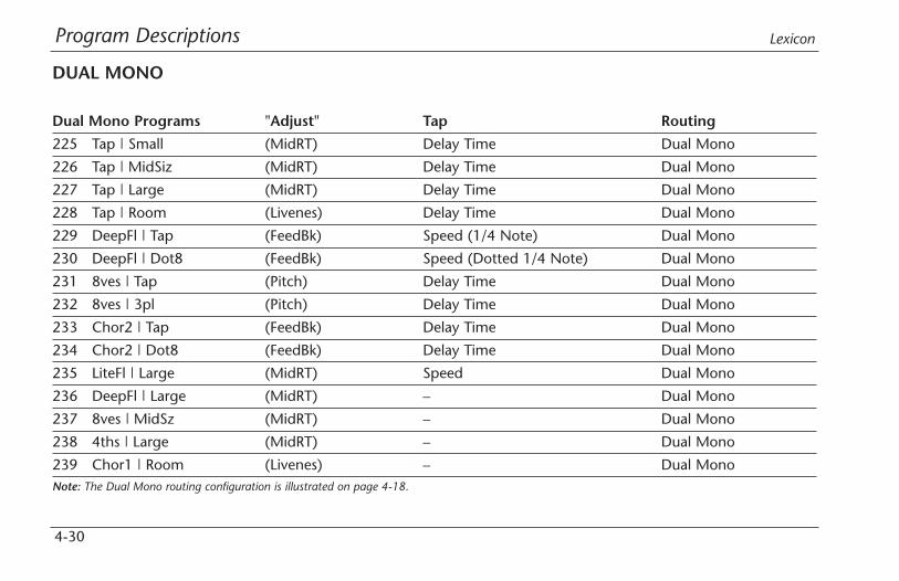
Program Descriptions Lexicon
4-30
DUAL MONO
Dual Mono Programs "Adjust" Tap Routing
225 Tap | Small (MidRT) Delay Time Dual Mono
226 Tap | MidSiz (MidRT) Delay Time Dual Mono
227 Tap | Large (MidRT) Delay Time Dual Mono
228 Tap | Room (Livenes) Delay Time Dual Mono
229 DeepFl | Tap (FeedBk) Speed (1/4 Note) Dual Mono
230 DeepFl | Dot8 (FeedBk) Speed (Dotted 1/4 Note) Dual Mono
231 8ves | Tap (Pitch) Delay Time Dual Mono
232 8ves | 3pl (Pitch) Delay Time Dual Mono
233 Chor2 | Tap (FeedBk) Delay Time Dual Mono
234 Chor2 | Dot8 (FeedBk) Delay Time Dual Mono
235 LiteFl | Large (MidRT) Speed Dual Mono
236 DeepFl | Large (MidRT) – Dual Mono
237 8ves | MidSz (MidRT) – Dual Mono
238 4ths | Large (MidRT) – Dual Mono
239 Chor1 | Room (Livenes) – Dual MonoNote: The Dual Mono routing configuration is illustrated on page 4-18.
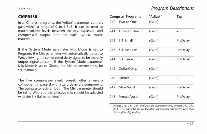
Program DescriptionsMPX 550
4-31
CMPRSSRIn all Cmprssr programs, the "Adjust" parameter controlsgain within a range of 0 to 9.5dB. It can be used tomatch volume levels between the dry, bypassed, andcompressed output obtained with typical musicmaterial.
If the System Mode parameter Mix Mode is set toProgram, the Mix parameter will automatically be set toWet, allowing the compressed delay signal to be the onlyoutput signal present. If the System Mode parameterMix Mode is set to Global, the Mix parameter must beset manually.
The five compressor-reverb presets offer a reverbcomponent in parallel with a zero-delay dry component.The compressor acts on both. The Mix parameter shouldbe set to Wet, and the effective mix should be adjustedwith the Efx Bal parameter.
Comprssr Programs "Adjust" Tap
240 Two to One (Gain) –
241 Three to One (Gain) –
242 3:1 Small (Gain) PreDelay
243 5:1 Medium (Gain) PreDelay
244 3:1 Large (Gain) PreDelay
245 GuitarComp (Gain) –
246 Limiter (Gain) –
247 Male Vocal (Gain) PreDelay
248 Female Vocal (Gain) PreDelay
* Presets 240, 241, 245, and 246 are compressor only. Presets 242, 243,244, 247, and 248 are combination compressor and reverb with DualStereo (Parallel) routing.
Program Descriptions Lexicon
4-32
DYNAMICS
Note:A few seconds after the Dynamics preset is loaded,the Dynamics name will flash briefly on the frontpanel display. This does not affect audio input oroutput.
Dynamics is intended for use in the studio, whendynamic processing of stereo signals is required. Becauseof its long delay, this preset is not recommended for usein a live performance or as a mix insert. It includes effectsthat perform peak expansion, compression, and tapesaturation in that order.
Dynamics includes nine parameters that are divided intothree Edit Pages. Peak expansion settings are controlledon the first page, compression settings are controlled onthe second page, and tape saturation settings arecontrolled on the third page. The first page also featuresa switch that selects between gain reduction and inputmetering.
PEAK EXPANSIONPeak expansion is used to raise the overall level of soundsources that rise above the adjustable peak expansionthreshold. In performances with a wide dynamic range,peak expansion can increase the level of low-level soundsources. For example, for a relatively quiet instrumentthat swells in volume without the desired impact, peakexpansion can raise the instrument level during the swell.
ExpThrsh (-31 to 0dB)
Controls the threshold above which expansion isapplied. Lower settings enable low-level sound sourcesto expand. Higher settings enable only very high-levelpeaks to expand.
ExpLvl (0.0dB to 5.89dB)
Controls the amount of expansion that is applied tosound sources that rise above the expansion threshold.The parameter setting defines the maximum increase insignal level due to expansion. Higher settings increasethe level of expansion applied. Maximum expansion isapplied to signals that rise well above the expansionthreshold for longer than 50ms.
Program DescriptionsMPX 550
4-33
Meters (GR, In)
Selects between gain reduction (GR) and input level (In)metering. (See page 4-35 for more information.)
COMPRESSIONCompression is used to lower the overall level of soundsources that rise above an adjustable compressionthreshold. Compression can be used to match the levelsof louder sources to those of quieter sources.
Ratio (1:1 to 10:1)
Determines the level of gain reduction applied when thesound source rises above the compression threshold. Itcan be set in ratios of 1:1, 1.60:1, 2.00:1, 2.66:1, 3.20:1,4.00:1, 5.33:1, 8.00:1 and 10:1. For each dB rise in inputto the compressor, the ratio indicates the fraction of thedB rise in output. For example, when Ratio is set to4.00:1, the output will rise 0.25dB for each dB rise ininput to the compressor. Higher settings will result inmore compression.
Thresh (-31 to -0dB)
Designates the compression threshold, the level thesound source must rise above before compression isapplied.
Attack (200 to 3.0msec)
Determines how fast the compressor responds to soundsources that rise above the compression threshold.Slower settings allow the signal to rise above thethreshold for short periods of time with minimalcompression.
Release (4.0 to .30sec)
Determines how fast compression is reduced whensound sources fall below the compression threshold.Slower settings reduce compression gradually. Fastersettings reduce compression more quickly, causing thelevel of the sound source to be tracked more closely.
. . . continued on page 4-34
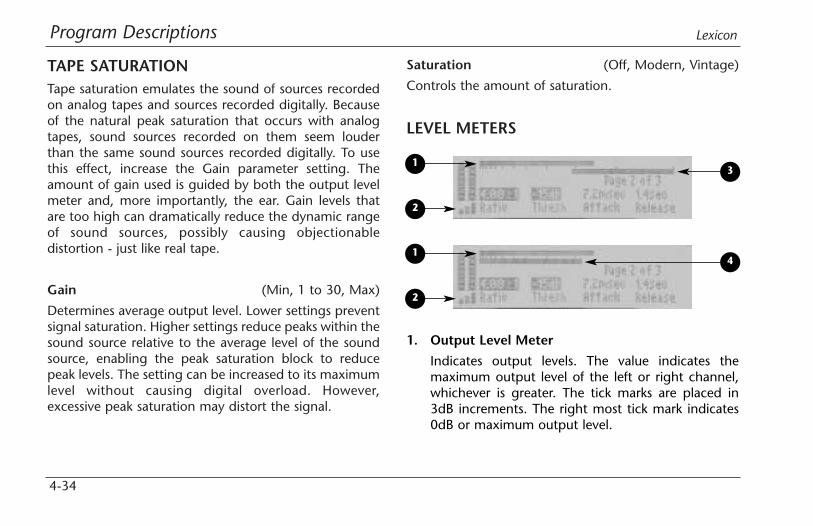
Program Descriptions Lexicon
4-34
TAPE SATURATIONTape saturation emulates the sound of sources recordedon analog tapes and sources recorded digitally. Becauseof the natural peak saturation that occurs with analogtapes, sound sources recorded on them seem louderthan the same sound sources recorded digitally. To usethis effect, increase the Gain parameter setting. Theamount of gain used is guided by both the output levelmeter and, more importantly, the ear. Gain levels thatare too high can dramatically reduce the dynamic rangeof sound sources, possibly causing objectionabledistortion - just like real tape.
Gain (Min, 1 to 30, Max)
Determines average output level. Lower settings preventsignal saturation. Higher settings reduce peaks within thesound source relative to the average level of the soundsource, enabling the peak saturation block to reducepeak levels. The setting can be increased to its maximumlevel without causing digital overload. However,excessive peak saturation may distort the signal.
Saturation (Off, Modern, Vintage)
Controls the amount of saturation.
LEVEL METERS
13
4
2
1
2
1. Output Level Meter
Indicates output levels. The value indicates themaximum output level of the left or right channel,whichever is greater. The tick marks are placed in3dB increments. The right most tick mark indicates0dB or maximum output level.

Program DescriptionsMPX 550
4-35
2. Peak Expansion Meter
Indicates the level of peaks above the peakexpansion threshold. Low-level peaks are shown asone or two graduated bars. Slightly higher peaks oflonger duration are shown as three graduated bars.High-level peaks are shown as three solid bars.
Note:Use the Meters parameter to select between gainreduction and input level metering.
3. Gain Reduction Meter
When the Meters parameter is set to GR, indicatesthe output level reduction due to compression. Thevalue shown indicates the maximum left or rightchannel gain reduction, whichever is greater.
The meter moves from right to left. The tick marksare placed in 3dB increments. The right-most tickmark represents 0dB or no gain reduction. Each tickmark proceeding from right to left indicates anadditional 3dB of gain reduction.
4. Input Meter
When the Meters parameter is set to In, indicates themaximum left or right channel input levels,whichever is greater. The associated tick marks areplaced in 3dB increments. The right-most tick markindicates 0dB or maximum input level.
TYPICAL MASTERING DYNAMICS CONTROLADJUSTMENTThe following is a common scenario for musical sourcesthat have not previously been compressed:
• For analog input sources, adjust the front panelInput Trim knob so the input meters peak in the -6dBrange. The input meters should never exceed the0dB level.
• Beginning at 0dB, reduce the setting of the ExpThrshparameter until peaks in the source material causethe peak expansion level meter to show 1 to 3graduated bars. High-level peaks in the sound source
. . . continued on page 4-36

Program Descriptions Lexicon
4-36
will cause the peak expansion meter to show threesolid bars for short periods of time. Increase theExpLvl parameter until the peaks in the sourcematerial sound slightly exaggerated. Then, reducethe setting until the peaks sound natural.
• Set the Ratio parameter to 4.00:1, the Attackparameter to 7.2msec, and the Release parameter to1.4sec. Beginning at 0dB, reduce the setting of theThresh parameter until the gain reduction metermoves between 0 and 3 to 6dB of gain reduction. Ifthe output level sounds unnatural, increase thesettings of the Attack and Release parameters. Ifoutput levels are too low after peaks occur, increasethe setting of the Release parameter. If output levelsare still too low after peaks occur, increase thesetting of the ExpLvl parameter.
• Beginning at 0, adjust the Gain parameter settinguntil the output level meter shows peaks above–3dB.
LIVE-FOH (FRONT OF HOUSE)Live-FOH programs are designed for live performances,with controls that are more convenient for live-soundengineers to operate. These programs use Dual Monoroutings to accommodate the sound reinforcementsystems (PAs) used in most small-to-mid-sized venues.Often, these systems provide limited channels and monoaux sends for effects.
For Live-FOH presets:
• Edit Page 1 contains the four most essentialparameters for the first effect, and Edit Page 2contains the four most essential parameters for thesecond effect. Non-essential parameters have beenremoved from the Edit Pages.
Typical Mastering Dynamics Control Adjustment (continued)

Program DescriptionsMPX 550
4-37
• In the delay programs, two delay level controls havebeen combined into the "Adjust" parameter: (Tap/Dly). These programs contain two delays. The first iscontrolled by tempo and generally used to createlonger delays and echoes. The second is setmanually with the Delay parameter, and can be usedto create a "slap" of 60 to 135ms.
The (Tap/Dly) parameter provides an inverse levelcontrol for these delays. The default setting providesequal levels of each. The tempo-controlled delay issuited for longer rhythm-sensitive effects, while themanually-controlled delay is suited for shorter times.However, both delays are capable of delivering a fullrange of delay times that can be crossfed into eachother for more extreme effects.
• The Dly/Reverb program is available with alternativeEDIT knob assignments (255). The first two EditPages are arranged with delay parameters on the leftand reverb parameters on the right. Thisarrangement splits effect controls left-to-right ratherthan page-to-page.
Live-FOH Programs "Adjust" Tap
250 Flange/Dly (Tap/Dly) Delay Time
251 Chorus/Dly (Tap/Dly) Delay Time
252 Flange/Rvb (Tap/Dly) –
253 Chorus/Rvb (Tap/Dly) –
254 Dly/Reverb (Tap/Dly) Delay Time
255 Dly/Reverb (Tap/Dly) Delay Time

Parameter Descriptions
5Parameter Graphics. . . . . . . . . . . . . . . . . . . . . . . . . . . . . . . . . . . 5-2
Parameter Glossary . . . . . . . . . . . . . . . . . . . . . . . . . . . . . . . . . . . 5-4

Parameter Descriptions Lexicon
5-2
PARAMETER GRAPHICSThe MPX 550 features graphic enhancements for each parameter, which appear on the front panel display whenevera parameter setting is changed. These graphics illustrate the point at which the selected setting falls within the entireparameter range, and provide a visual indication of the parameter’s function. As the setting changes, the graphic alsochanges to reflect the new setting. Examples are shown below and on the following page. To view other parametergraphics, change the setting of the desired parameter.
When the Decay parameter setting is changed, the graphics pictured below appear.
When the HF Rlloff parameter setting is changed, the graphics pictured below appear.

Parameter DescriptionsMPX 550
5-3
When the Mix parameter setting is changed, the graphics pictured below appear.
When a delay parameter setting is changed, the graphics pictured below appear.
When the Level parameter setting is changed, the graphics pictured below appear.
When the Width parameter setting is changed, the graphics pictured below appear.
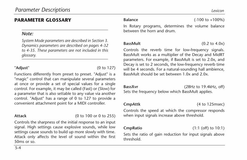
Parameter Descriptions Lexicon
5-4
PARAMETER GLOSSARY
Note:System Mode parameters are described in Section 3.Dynamics parameters are described on pages 4-32to 4-35. These parameters are not included in thisglossary.
"Adjust" (0 to 127)
Functions differently from preset to preset. "Adjust" is a"magic" control that can manipulate several parametersat once or provide a set of special values for a singlecontrol. For example, it may be called (Fast) or (Slow) fora parameter that is also settable to any value via anothercontrol. "Adjust" has a range of 0 to 127 to provide aconvenient attachment point for a MIDI controller.
Attack (0 to 100 or 0 to 255)
Controls the sharpness of the initial response to an inputsignal. High settings cause explosive sounds, while lowsettings cause sounds to build up more slowly with time.Attack only affects the level of sound within the first50ms or so.
Balance (-100 to +100%)
In Rotary programs, determines the volume balancebetween the horn and drum.
BassMult (0.2 to 4.0x)
Controls the reverb time for low-frequency signals.BassMult works as a multiplier of the Decay and MidRTparameters. For example, if BassMult is set to 2.0x, andDecay is set to 2 seconds, the low-frequency reverb timewill be 4 seconds. For a natural-sounding hall ambience,BassMult should be set between 1.0x and 2.0x.
BassXvr (28Hz to 19.4kHz, off)Sets the frequency below which BassMult applies.
CmpAttk (4 to 125msec)
Controls the speed at which the compressor respondswhen input signals increase above threshold.
CmpRatio (1:1 (off) to 10:1)
Sets the ratio of gain reduction for input signals abovethreshold.
Parameter DescriptionsMPX 550
5-5
CmpRels (4 to 250msec)
Controls the rate at which the compressor relaxes whencompressed input signal levels fall.
Decay (73ms to 19.61sec or 24ms to 6.53sec)
Controls reverb time for mid frequency signals. InAmbience programs, Decay controls the length of theambience "tail".
Depth (0 to 100%)
Controls the level of volume modulation.
Diffusion (0 to 100%)
Controls the degree to which initial echo densityincreases over time. High settings result in a high initialbuildup of echo density. (Echo density is also affected bySize, with smaller spaces sounding denser.)
Dly Fbk (0 to 100%)
Serves as a master control determining the feedback ofleft into left and right into right.
Dly HiCut (28Hz to 19.4kHz, off)
Appears in Dual programs where one effect is Dly/Eko,providing independent control over the Dly/Ekohigh-frequency output. Dly HiCut applies a high-cutfilter similar to HF Rlloff to the Delay/Echo effect.
Dly Lvl (off, -24dB to 0dB)
Controls the overall level of the signal fed into the Delay,Echo effect.
Dly Lvl 1, 2, 3 (off, -48dB to 0dB)
Controls the levels of voice set 1, 2, or 3 for both the leftand right channels.
Dly XFbk (0 to 100%)
Determines the feedback of left into right and right intoleft.
Parameter Descriptions Lexicon
5-6
DlyTapLvl (off, -48 to 0dB)
Appears in dual programs where one effect is Delay/Echoand one or more delay voice is controlled by Tap.DlyTapLvl controls the level of the Tap-controlled voicethat is mixed into the Delay/Echo effect.
Drum Dep (0 to 100%)
In Rotary programs, determines the amount ofmodulation produced by the drum.
Drum Res (-100 to +100%)
In Rotary programs, determines the amount ofresonance, i.e. signal, fed back into the effect.
Duration (140 to 700ms)
In Gate/Inv programs, determines the length of time thatpasses before the output is cut off.
Efx Bal (100:0% to 0:100%)
Controls the relative amounts of the two effects in Dualprograms. In a Dual Stereo (Parallel), Mono Split, or DualMono configuration, this splits the signal to be fed intothe two effects. In a Cascade configuration, it also allowssome of the signal to bypass either of the two effects.
EkoDly L, R (0ms to 1.198sec)
Control the timing of single reflections that occur early inthe decay in the reverb programs. These reflectionssimulate the sound sometimes heard off the back wall ofa stage or other reflective surface.
EkoFbk L, R (-100 to 100%)
Control the amount of repeating echo that simulates aflutter echo between parallel walls in the reverbprograms. The range of these parameters is from -100%to 100%, with negative values producing a polarityreversal. High settings can cause signal overload.
HF Rlloff (28Hz to 19.4kHz, off)
Sets the high-frequency cutoff of a low-pass filter.

Parameter DescriptionsMPX 550
5-7
HighSlope and LowSlope (-16 to +15)
Determine the shape of the reverb envelope for lowfrequencies. HighSlope and LowSlope are found only inthe Gate/Inv programs. When LowSlope is set to 0, thelevel of low reverb remains unchanged over its duration,then cuts off abruptly. Setting LowSlope above 0 causesthe level of low-frequency reverb to rise smoothly fromsoft to loud until the sound is cut off. The greater theslope, the softer the initial reverberation and the morepronounced its rise. When set to a negative value, thelow-frequency reverb drops to a quieter level beforecutoff. HighSlope is similar to LowSlope, but applies tomiddle and high frequencies.
Horn Dep (0 to 100%)
In Rotary programs, determines the amount ofmodulation produced by the horn.
Horn Res (-100 to +100%)
In Rotary programs, determines the amount ofresonance, i.e. signal fed back into the effect.
Intrvl (Varies)
Controls the amount of pitch-shift applied. Intrvl valuesare in semi-tones. Pch values are in Cents (1/100th of asemi-tone). These values are additive.
L Dly 1, 2, 3 (0ms to 5.060sec)
Sets the delay time of left voice 1, 2, or 3. The Dly/Ekoeffect has three independent voices on each side.
Level (0 to 100%)
Determines the amount of wet signal present in theoutput. It functions similar to Mix, except it affects thewet component only. Level is generally used to balancethe overall output of two or more programs when Mix isset to wet.
LowSlope and HighSlope (-16 to +15)
See HighSlope and LowSlope.
Parameter Descriptions Lexicon
5-8
Mix (Dry, 1 to 99%, Wet)
Mix controls the ratio of unprocessed (Dry) andprocessed (Wet) signal in the output. When the MPX 550is patched into a console, this parameter should almostalways be set to Wet.
MstrRate (0 to 100%)
In Rotary programs, serves as a master rate controlaffecting both the horn and drum rates.
Pch Fbk (L), (R) (-100% to +100%)
Controls the amount of feedback through the Pitch pre-sets, resulting in repeated echoes with pitch progressingup or down.
Pch (L), (R/S) (-2400 to 2600)
Control the amount of pitch-shift applied to the left andright channels. For true stereo programs, the Pch(L)parameter is not available and the Pch(R/S) parametermeans stereo. For mono programs, the Pch(L) and (R/S)parameters mean left and right respectively.
Pitch-shifting requires some time shifting. A true stereo(not merely Dual Mono) signal contains componentsthat are common to the left and right signals. A properstereo image is maintained only if the phase relationshipbetween the left and right signals is maintained. Thisrequires that the exact same computation be applied toboth channels, which is why only one control is provid-ed for Pitch presets.
PDly (L), (R) (0 to 100ms)
Controls the amount of "look-ahead" required by thepitch-shift algorithm. Some amount of pre-delay isalways in effect, even when this parameter is set to 0.
Phase (0 to 270deg)
Determines the relative timing between the left and rightchannels.
PreDelay (0ms to 1.198sec)
Controls the time delay between the input of signal andthe onset of reverberation.
Parameter DescriptionsMPX 550
5-9
R Dly 1, 2, 3 (0ms to 5.060sec)
Sets the delay time of right voice 1, 2, or 3. The Dly/Ekoeffect has three independent voices on each side.
Rate (0 to 50.05Hz)
Controls modulation speeds.
Res 1, 2 (-100 to +100%)
In Chorus programs, control the amount of feedbacksignal.
Resonanc (-100 to +100%)
In Flange programs, controls the amount of feedback.
Rt HC (28Hz to 19.4kHz, off)
Sets the frequency above which high frequencies arerolled off in the reverberated signal, causing reverberatedsignals to grow progressively darker. This results in amore natural sound because it simulates the effect of airabsorption in a real hall. Setting this parameter to alow- frequency dampens the audio as it re-circulates, andconsequently can actually shorten the reverb time.
RvbLvl (off, -48dB to 0dB)
In Ambience programs, controls the amount of "extra"longer-decay reverb added to the effect. In Ambience,short-decay early reflections create a real-room sound.
Shape (0 to 255)
Controls the buildup of the early reflections that mostaudibly create the sound of a real room. Shape andSpread work together; if either is set to 0, the other hasno effect.
Size (4.0 to 76.0m)
Sets the rate of echo density buildup after the initialperiod (which is controlled by Diffusion). It also acts as amaster control for Decay. Size changes a reverb soundfrom very small to very large. It is recommended to setthe Size control to the approximate size of the acousticspace that is being created before adjusting otherparameters. The size in meters is roughly equal to thelongest dimension of the space. (Adjusting the Sizeparameter causes the program to re-load.)

Parameter Descriptions Lexicon
5-10
Speed (0 to 5000)
In Flange programs, controls how rapidly the two"flange" voices move.
Speed 1, 2 (0 to 5000)
In Chorus programs, control the rates at which thevarious voices sweep through frequency.
Spread (0 to 255)
Controls the timing between the initial reflections thatmost audibly create the sound of a real room. Shape andSpread work together; if either is set to 0, the other hasno effect.
Sweep (0 to 100ms)
In Flange programs, determines the maximum amountof time-delay applied to each voice.
Sweep 1, 2 (0 to 100ms)
In Chorus programs, control the amount of frequencyvariation for two different collections of voices. (TheChorus effect simulates six voices with slightly varyingpitch. Separate controls are available over two sets ofthree voices each.)
Threshld (-32 to -0dB)
Controls the level above which signals are compressed.
Tune 1, 2 (0 to 100%)
In Detune programs, determines the amount ofdetuning applied to voices 1 and 2.

Parameter DescriptionsMPX 550
5-11
Wavform (See Below)
In Tremolo programs, determines volume modulation.Settings are defined as follows:
Setting Description
Sine Smooth modulation with polarity reversal.
Rectified Smooth modulation with no polaritySine reversal.
Triangle Linear ramp up and down.
Sawtooth Linear ramp up with sudden reduction.
Square Level modulates between maximumand minimum.
Width (0 to 100%)
Determines the effective separation between the left andright channels.
MIDI Operation
6Learn Mode . . . . . . . . . . . . . . . . . . . . . . . . . . . . . . . . . . . . . . . . 6-2
MIDI Channel Assignment . . . . . . . . . . . . . . . . . . . . . . . . . . . . . . 6-2
Program Change Messages . . . . . . . . . . . . . . . . . . . . . . . . . . . . . 6-3Loading Programs • Activating Bypass or Tap Functions
Continuous Controllers . . . . . . . . . . . . . . . . . . . . . . . . . . . . . . . . 6-4
MIDI Clock . . . . . . . . . . . . . . . . . . . . . . . . . . . . . . . . . . . . . . . . . 6-6
MIDI Dumps. . . . . . . . . . . . . . . . . . . . . . . . . . . . . . . . . . . . . . . . 6-6
Sysex Messages. . . . . . . . . . . . . . . . . . . . . . . . . . . . . . . . . . . . . . 6-7
MIDI Implementation Chart. . . . . . . . . . . . . . . . . . . . . . . . . . . . . 6-8

MIDI Operation Lexicon
6-2
LEARN MODELearn Mode enables the MPX 550 to "learn" MIDIProgram Change and Continuous Controller messages.To activate and deactivate Learn Mode, press the Storeand Tap/Cancel buttons simultaneously. The Store andTap/Cancel LEDs will light to indicate that Learn Mode isactive. The front panel display will then show the currentpatching for EDIT knobs 1 to 4 (Edit Page 1). To accessknobs 5 to 20, press the Edit Pages to cycle to the desiredEdit Page.
The unit supports learned patches for Bypass and Tap, aswell as all available parameters controlled with the frontpanel Edit knobs.
MIDI CHANNEL ASSIGNMENTA single, selectable MIDI channel is used for all MPX 550messages. This channel can be assigned in System Modewith the MIDI Channel parameter.
Note:A MIDI channel should be assigned before MIDIfeatures are used.
The parameters controlled with the EDITknobs can be patched to Continuous
Controller messages.
Bypass and Tap/Cancel can bepatched to Program Change andContinuous Controller messages.
Press the Store and Tap/Cancelbuttons simultaneously to activate
and deactivate Learn Mode.
Program Changemessages can be used
to load programs.

MIDI OperationMPX 550
6-3
PROGRAM CHANGE MESSAGES
LOADING PROGRAMSStandard MIDI Program Change messages can be usedto load all 255 presets and 64 user programs. The unitconforms to the use of MIDI Continuous Controller 32 toexecute Bank Select messages. MPX 550 program banksare ordered numerically from 0 to 27, beginning withthe Plate Bank. (See the table at the right for additionalbank numbers.)
Any program can be loaded by selecting its bank withController 32, then sending the appropriate ProgramChange message.
For example, if the Plate Bank is selected:
• Sending Program Change 1 will load the first Plateprogram (Small Plate).
• Sending Controller 32 with a value of 27 followed byProgram Change 1 will load the first program in theUser Bank.
0 Plate1 Gate/Inv2 Hall3 Chamber4 Ambience5 Room6 Tremolo7 Rotary8 Chorus9 Flange
10 Detune11 Pitch12 Dly/Eko13 Special FX14 Flng-Dly15 Pch-Dly16 Chor-Dly17 Dly-Rvb18 Flng-Rvb
19 Pch-Rvb20 Chor-Rvb21 MSplit Dly22 MSplit Rvb23 Dual Mono24 Cmprssr25 Dynamics26 Live-FOH27 User
• Sending Controller 32 with a value of 1 followed byProgram Change 2 will load the second program(Slope Down) in the Gate/Inv Bank.
Once a bank is selected, all subsequent Program Changemessages will select programs within that bank until anew value for Controller 32 is received, or until anotherprogram or bank is selected with the front panelPROGRAM knob.
MIDI Program Change messages can be disabled inSystem Mode with the MIDI Program Changeparameter.
MIDI Program Banks
MIDI Operation Lexicon
6-4
ACTIVATING BYPASS OR TAP FUNCTIONSThe unit can recognize MIDI Program Change messages100 to 127 (101 to 128 on some MIDI devices) foractivating Bypass or Tap functions.
To assign a Program Change message to the Bypass orTap controls:
1. Simultaneously press the Store and Tap buttons toactivate Learn mode.
2. Press the desired front panel button - Bypass or Tap.The front panel display will indicate the currentpatch on the selected control.
3. Send the MIDI Program Change message to theMPX 550. The front panel display will indicate thenew patch on the control, and "Stored" will appearbriefly in the message area.
4. Press the Store button to commit the assignment.
5. Simultaneously press the Store and Tap buttons todeactivate Learn Mode.
Some MIDI controllers do not allow repeated ProgramChange messages to be sent with a single button. Toassist these controllers, the unit also recognizes the nexthighest Program Change message with each ProgramChange message it learns for Bypass and Tap. Forinstance, if Program Change 20 is learned as the sourcefor Bypass, Program Change 21 will also control Bypassfunctions. To avoid conflicting Bypass and Tapassignments, leave a space between the assignments ofthese two buttons.
CONTINUOUS CONTROLLERSThe unit recognizes Pitch Bend, AfterTouch, and MIDIContinuous Controllers 1 to 31 and 33 to 119.
To learn a Continuous Controller:
1. Simultaneously press the Store and Tap buttons toactivate Learn mode.
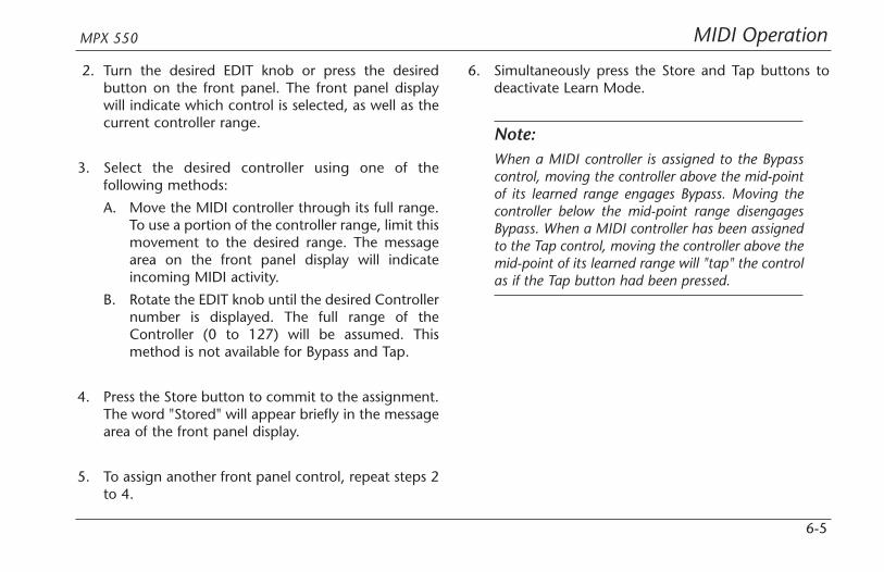
MIDI OperationMPX 550
6-5
2. Turn the desired EDIT knob or press the desiredbutton on the front panel. The front panel displaywill indicate which control is selected, as well as thecurrent controller range.
3. Select the desired controller using one of thefollowing methods:
A. Move the MIDI controller through its full range.To use a portion of the controller range, limit thismovement to the desired range. The messagearea on the front panel display will indicateincoming MIDI activity.
B. Rotate the EDIT knob until the desired Controllernumber is displayed. The full range of theController (0 to 127) will be assumed. Thismethod is not available for Bypass and Tap.
4. Press the Store button to commit to the assignment.The word "Stored" will appear briefly in the messagearea of the front panel display.
5. To assign another front panel control, repeat steps 2to 4.
6. Simultaneously press the Store and Tap buttons todeactivate Learn Mode.
Note:When a MIDI controller is assigned to the Bypasscontrol, moving the controller above the mid-pointof its learned range engages Bypass. Moving thecontroller below the mid-point range disengagesBypass. When a MIDI controller has been assignedto the Tap control, moving the controller above themid-point of its learned range will "tap" the controlas if the Tap button had been pressed.

MIDI Operation Lexicon
6-6
MIDI CLOCKThe unit recognizes MIDI Clock messages and appliesthe tempo (40 to 400bpm) to programs that use TapTempo. Connect a MIDI device that outputs MIDI Clock,such as the MPX R1 foot controller or a MIDI sequencer,to the MPX 550 MIDI IN connector to have the MPX 550automatically recognize and begin to process MIDI Clockmessages. When the tempo of the connected devicechanges, the unit will automatically adjust its delay timesand modulation rates to match the new tempo.
This feature can be disabled with the System Modeparameter MIDI Clock In.
Note:When System Mode is active, the unit will notrespond to MIDI Clock messages. Once SystemMode is deactivated, the unit will resumeresponding to MIDI Clock messages.
MIDI DUMPSMIDI Dumps can be used to save the user programs, theselected program, or the System Mode settings andLearned Patch assignments to a storage device (typicallya MIDI sequencer). MIDI Dumps are performed inSystem Mode (see page 3-8).
To perform a dump of the user programs, the selectedprogram, or the System Mode settings and LearnedPatches:
1. Press the front panel System button. The System LEDwill light to indicate that System Mode is active.
2. Use the EDIT knob 1 to select:
• Dump User Bank
Executes a dump of user programs. Use Editknob 3 to select the desired range of userprograms: (1-16), (17-32), (33-48), or (49 to64). When a user program dump is returned tothe unit from a MIDI storage device, the unitsaves it in the appropriate User Bank locations.

MIDI OperationMPX 550
6-7
• Dump Current Program
Executes a dump of the selected program.
• Dump System Data
Executes a dump of System Mode settings andLearned Patch assignments.
3. Press Store to execute the dump.
4. Press System to deactivate System Mode.
Note:MIDI Dumps will not be executed unless the SystemMode parameter MIDI Out/Thru is set to Out (seepage 3-6).
SYSEX MESSAGESMIDI Sysex messages can be used to access all algorithmparameters. More information about using this advancedfeature with the MPX 550 and other Lexicon products isavailable at www.lexicon.com. The website offersinstructions, sample messages, and a complete table ofparameter Sysex addresses.
Note:Executing MIDI Sysex messages is a complicatedprocess. Please observe the cautionary notesincluded on the website.

MIDI Operation Lexicon
6-8
Function Transmitted Recognized Remarks
Basic Default X 1 Selected in System ModeChannel Channel X 1-16
Mode Default Mode 2Messages X XAltered X
Note True Voice X XNumber
Velocity Note ON X X (Off=9n, v=0)Note OFF X X
After Keys X X Used as controllerTouch Channels X OX Selected in System Mode
Pitch X OX Used as controllerBlender Learned
Control X OX 1 to 119 (0 to 32 used as Bank Select)Change Learned
MIDI IMPLEMENTATION CHART
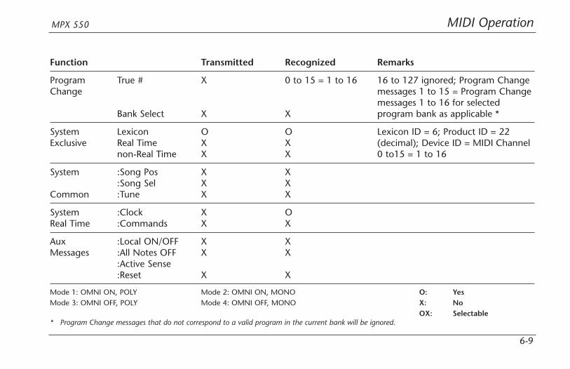
MIDI OperationMPX 550
6-9
Function Transmitted Recognized Remarks
Program True # X 0 to 15 = 1 to 16 16 to 127 ignored; Program ChangeChange messages 1 to 15 = Program Change
messages 1 to 16 for selectedBank Select X X program bank as applicable *
System Lexicon O O Lexicon ID = 6; Product ID = 22 Exclusive Real Time X X (decimal); Device ID = MIDI Channel
non-Real Time X X 0 to15 = 1 to 16
System :Song Pos X X:Song Sel X X
Common :Tune X X
System :Clock X OReal Time :Commands X X
Aux :Local ON/OFF X XMessages :All Notes OFF X X
:Active Sense:Reset X X
Mode 1: OMNI ON, POLY Mode 2: OMNI ON, MONO O: YesMode 3: OMNI OFF, POLY Mode 4: OMNI OFF, MONO X: No
OX: Selectable* Program Change messages that do not correspond to a valid program in the current bank will be ignored.

Appendix
ASpecifications . . . . . . . . . . . . . . . . . . . . . . . . . . . . . . . . . . . . . . . A-2
Declaration of Conformity . . . . . . . . . . . . . . . . . . . . . . . . . . . . . . A-3

Appendix Lexicon
A-2
SPECIFICATIONS
Audio InputsConnectors XLR, T/R/S balancedLevel +8 to +20dBu full-scaleImpedance 50K balanced
25K unbalancedA/D 24-bits
20Hz to 20kHz±1dBDynamic Range 105dB, typicalCrosstalk -96dB@1kHz
Analog Audio OutputsConnectors XLR, T/R/S balancedLevel +26dBu balanced
+20dBu unbalancedImpedance <600ΩD/A 24-bits
20Hz to 20kHz±1dBDynamic Range 101dB, typicalCrosstalk -96dB@1kHz
Digital Audio Inputs and OutputsConnectors Coaxial RCA
S/PDIF(IEC-958, CP-340)
System Sample Rates44.1kHz, 48kHz (Internal Clock andS/PDIF Input)
Front Panel Display150x32 LCD, backlit
FootswitchTip/Ring/Sleeve phone jack for Bypassand Tap (optional)
MIDI Interface ConnectorsIN, OUT/THRU
Power Requirements90 to 250V, 50 to 60Hz; 12.5W, 3-pin IECconnector
Dimensions (W x H x D)Width 19 inches (483mm)Height 1.75 inches (45mm)Depth 4 inches (102mm)
Weight3 pounds (1.4kg)
EnvironmentOperatingTemperature 32 to 104˚F (0 to 40˚C)RelativeHumidity 95% non-condensing
RFI/ESDFCC Class BEuropean EMC Directive 89/336/ECC
Specifications are subject to change without notice.

AppendixMPX 550
A-3
DECLARATION OF CONFORMITY
Application of Council Directive(s): 73/23/EEC, 89/336/EEC, and 93/68/EEC
Standard(s) to which Conformity is Declared: EN 55103-1, EN 55103-2, and EN 60065: 1998
Manufacturer: Lexicon, Inc., 3 Oak Park, Bedford, MA 01730-1441 USAThe equipment identified here conforms to the Directive(s) andStandard(s) specified above.
Type of Equipment: Dual Channel Processor
Model: Lexicon MPX 550
Date: February 2002
Lexicon, Inc.Vice President of Engineering
3 Oak ParkBedford, MA 01730-1441 USA
Tel: 781-280-0300Fax: 781-280-0490
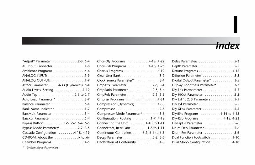
Index
I“Adjust” Parameter . . . . . . . . . . . . .2-3, 5-4AC Input Connector . . . . . . . . . . . . . . . .1-8Ambience Programs . . . . . . . . . . . . . . . .4-6ANALOG INPUTs . . . . . . . . . . . . . . . . . .1-9ANALOG OUTPUTs . . . . . . . . . . . . . . . .1-9Attack Parameter . . . . .4-33 (Dynamics), 5-4Audio Levels, Setting . . . . . . . . . . . . . .1-12Audio Tap . . . . . . . . . . . . . . . . . .2-6 to 2-7Auto Load Parameter* . . . . . . . . . . . . . .3-7Balance Parameter . . . . . . . . . . . . . . . . .5-4Bank Name Indicator . . . . . . . . . . . . . . .1-7BassMult Parameter . . . . . . . . . . . . . . . .5-4BassXvr Parameter . . . . . . . . . . . . . . . . .5-4Bypass Button . . . . . . . . . .1-5, 2-7, 6-4, 6-5Bypass Mode Parameter* . . . . . . . . .2-7, 3-5Cascade Configuration . . . . . . . .4-18, 4-19CD-ROM, About the . . . . . . . . . . . .ix to xivChamber Programs . . . . . . . . . . . . . . . .4-5
Chor-Dly Programs . . . . . . . . . . .4-18, 4-22Chor-Rvb Programs . . . . . . . . . . .4-18, 4-26Chorus Programs . . . . . . . . . . . . . . . . .4-10Clear User Bank . . . . . . . . . . . . . . . . . . .3-9Clock Source Parameter* . . . . . . . . . . . .3-4CmpAttk Parameter . . . . . . . . . . . . .2-5, 5-4CmpRatio Parameter . . . . . . . . . . . .2-5, 5-4CmpRels Parameter . . . . . . . . . . . . .2-5, 5-5Cmprssr Programs . . . . . . . . . . . . . . . .4-31Compression (Dynamics) . . . . . . . . . . .4-33Compressor . . . . . . . . . . . . . . . . . . . . . .2-5Compressor Mode Parameter* . . . . . . . .3-5Configuration, Routing . . . . . . . . .1-7, 4-18Connecting the Unit . . . . . . . .1-10 to 1-11Connectors, Rear Panel . . . . . . .1-8 to 1-11Continuous Controllers . . . . .6-2, 6-4 to 6-5Decay Parameter . . . . . . . . . . . . . . .5-2, 5-5Declaration of Conformity . . . . . . . . . . .A-3
Delay Parameters . . . . . . . . . . . . . . . . . .5-3Depth Parameter . . . . . . . . . . . . . . . . . .5-5Detune Programs . . . . . . . . . . . . . . . . .4-12Diffusion Parameter . . . . . . . . . . . . . . . .5-5Digital Output Parameter* . . . . . . . . . . .3-5Display Brightness Parameter* . . . . . . . .3-7Dly Fbk Parmameter . . . . . . . . . . . . . . . .5-5Dly HiCut Parameter . . . . . . . . . . . . . . .5-5Dly Lvl 1, 2, 3 Parameters . . . . . . . . . . . .5-5Dly Lvl Parameter . . . . . . . . . . . . . . . . . .5-5Dly XFbk Parameter . . . . . . . . . . . . . . . .5-5Dly/Eko Programs . . . . . . . . . .4-14 to 4-15Dly-Rvb Programs . . . . . . . . . . . .4-18, 4-23DlyTapLvl Parameter . . . . . . . . . . . . . . .5-6Drum Dep Parameter . . . . . . . . . . . . . . .5-6Drum Res Parameter . . . . . . . . . . . . . . .5-6Dual Function Footswitch . . . . . . . . . . .1-10Dual Mono Configuration . . . . . . . . . . .4-18
* System Mode Parameters

Index Lexicon
I-2
Dual Mono Programs . . . . . . . . .4-18, 4-30Dual Programs . . . . . . . . . . . . .4-18 to 4-30Dual Stereo (Parallel) Configuration . . . .4-18Dump Current Program . . . . . . . . .3-8, 6-7Dump System Data . . . . . . . . . . . . .3-8. 6-7Dump User Bank . . . . . . . . . . . . . . .3-8, 6-6Duration Parameter . . . . . . . . . . . . . . . .5-6Dynamics . . . . . . . . . . . . . . . .4-32 to 4-36EDIT Knobs . . . . . . . . . . . . . . .1-5, 1-7, 2-3Edit Pages Button . . . . . . . . . . . . . .1-4, 2-3Editing Programs . . . . . . . . . . . . . . . . . .2-3Efx Bal Parameter . . . . . . . . . . . . .4-19, 5-6EkoDly L, R Parameters . . . . . . . . . . . . .5-6EkoFbk L, R Parameters . . . . . . . . . . . . . .5-6ExpLvl Parameter (Dynamics) . . . . . . . .4-32ExpThrsh Parameter (Dynamics) . . . . . .4-32Factory Init . . . . . . . . . . . . . . . . . . . . . .3-9Flange Programs . . . . . . . . . . . . . . . . .4-11Flng-Dly Programs . . . . . . . . . . . .4-18, 4-20Flng-Rvb Programs . . . . . . . . . . .4-18, 4-24Footswitch Connector . . . . . . . . . .1-8, 1-10Front Panel . . . . . . . . . . . . . . . . .1-4 to 1-7Front Panel Display . . . . . . . .1-5, 1-6 to 1-7Gain Parameter (Dynamics) . . . . . . . . .4-34Gain Reduction Meter (Dynamics) . . . . .4-35Gate/Inv Programs . . . . . . . . . . . . . . . . .4-3
Global Tempo . . . . . . . . . . . . . . . . . . . .2-7Hall Programs . . . . . . . . . . . . . . . . . . . .4-4HF Rlloff Parameter . . . . . . . . . . . . .5-2, 5-6HighSlope Parameter . . . . . . . . . . . . . . .5-7Horn Dep Parameter . . . . . . . . . . . . . . .5-7Horn Res Parameter . . . . . . . . . . . . . . . .5-7Input Level Meters . . . . . . . . . . . . . . . . .1-6Input Levels, Setting . . . . . . . . . . . . . . .1-12Input Meter (Dynamics) . . . . . . . . . . . .4-35Input Source Parameter* . . . . . . . . . . . .3-4Input Trim Knob . . . . . . . . . . . . . . . . . .1-4Input/OVL Indicator . . . . . . . . . . .1-6 to 1-7Inputs, Rear Panel . . . . . . . . . . .1-8 to 1-11Inspection Instructions . . . . . . . . . .ix to xivIntrvl Parameter . . . . . . . . . . . . . . . . . . .5-7L Dly 1, 2, 3 Parameters . . . . . . . . . . . . .5-7Learn Mode . . . . . . . . . . . . . . . . . . . . . .6-2Level Meters (Dynamics) . . . . .4-34 to 4-35Level Parameter . . . . . . . . . . . . . . .5-3, 5-7Limited Warranty . . . . . . .Inside Back CoverLive-FOH Programs . . . . . . . . .4-36 to 4-37Load Button . . . . . . . . . . . . . . .1-5, 2-2, 2-3Loading Programs . . . . . . . . . . . . . .2-2, 6-3LowSlope Parameter . . . . . . . . . . . . . . .5-7Mastering Dynamics . . . . . . . . .4-32 to 4-36Matching Rhythm . . . . . . . . . . . . . . . . .2-6
Memory Protect Parameter* . . . . . . . . . .3-7Messages, Front Panel Display . . . . . . . .1-7Meters Parameter (Dynamics) . . . . . . . .4-33MIDI Channel Assignment . . . . . . . . . . .6-2MIDI Channel Parameter* . . . . . . . .3-6, 6-2MIDI Clock . . . . . . . . . . . . . . . . . . . . . .6-6MIDI Clock Parameter* . . . . . . . . . .3-6, 6-6MIDI Dumps . . . . . . . . .3-3, 3-8, 6-6 to 6-7MIDI Implementation Chart . . . . .6-8 to 6-9MIDI IN Connector . . . . . . . . . . . . . . . .1-8MIDI Learn Mode . . . . . . . . . . . . . . . . .6-2MIDI OUT/THRU Connector . . . . . . . . . .1-8MIDI Out/Thru Parameter* . . . . . . .3-6, 6-7MIDI Patches Parameter* . . . . . . . . . . . .3-6MIDI Program Banks . . . . . . . . . . . . . . .6-3MIDI Program Change Parameter* . . . . .3-6Mix Mode Parameter* . . . . . . . . . . . . . .3-5Mix Parameter . . . . . . . . . . . . . . . .5-3, 5-8Mono Split Configuration . . . . . . . . . . .4-18MPX 550, About the . . . . . . . . . .1-2 to 1-3MSplit Dly Programs . . . . . . . . . .4-18, 4-27MSplit Rvb Programs . . . .4-18, 4-28 to 4-29MstrRate Parameter . . . . . . . . . . . . . . . .5-8Operating Mode Parameter* . . . .3-6 to 3-7Output Level Meter (Dynamics) . . . . . .4-34 Output Level Parameter* . . . . . . . . . . . .3-4
* System Mode Parameters
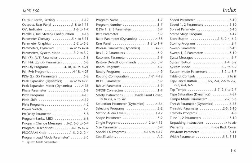
IndexMPX 550
I-3
Output Levels, Setting . . . . . . . . . . . . .1-12Outputs, Rear Panel . . . . . . . . . .1-8 to 1-11OVL Indicator . . . . . . . . . . . . . . .1-6 to 1-7Parallel (Dual Stereo) Configuration . . .4-18Parameter Glossary . . . . . . . . . .5-4 to 5-11Parameter Graphics . . . . . . . . . . .5-2 to 5-3Parameters, Dynamics . . . . . . .4-32 to 4-34Parameters, System Mode . . . . . .3-2 to 3-7Pch (R), (L/S) Parameter . . . . . . . . . . . . .5-8Pch Fbk (L), (R) Parameters . . . . . . . . . . .5-8Pch-Dly Programs . . . . . . . .4-18, 4-19, 4-21Pch-Rvb Programs . . . . . . . . . . . .4-18, 4-25PDly (L), (R) Parameters . . . . . . . . . . . . .5-8Peak Expansion (Dynamics) . . .4-32 to 4-33Peak Expansion Meter (Dynamics) . . . .4-35Phase Parameter . . . . . . . . . . . . . . . . . .5-8Pitch Programs . . . . . . . . . . . . . . . . . .4-13Pitch Shift . . . . . . . . . . . . . . . . . . . . . .4-19Plate Programs . . . . . . . . . . . . . . . . . . . .4-2Power Switch . . . . . . . . . . . . . . . . . . . . .1-5PreDelay Parameter . . . . . . . . . . . . . . . .5-8Program Banks, MIDI . . . . . . . . . . . . . . .6-3Program Change Messages . .6-2, 6-3 to 6-4Program Descriptions . . . . . . . . .4-1 to 4-37PROGRAM Knob . . . . . . . . . . .1-5, 2-2, 2-4Program Load Mode Parameter* . . . . . . .3-5
Program Name . . . . . . . . . . . . . . . . . . .1-7Program Number . . . . . . . . . . . . . . . . . .1-7R Dly 1, 2, 3 Parameters . . . . . . . . . . . . .5-9Rate Parameter . . . . . . . . . . . . . . . . . . .5-9Ratio Parameter (Dynamics) . . . . . . . . .4-33Rear Panel . . . . . . . . . . . . . . . . . .1-8 to 1-9Release Parameter (Dynamics) . . . . . . .4-33Res 1, 2 Parameters . . . . . . . . . . . . . . . .5-9Resonanc Parameter . . . . . . . . . . . . . . . .5-9Restore Default Commands . . . . . . .3-3, 3-9Room Programs . . . . . . . . . . . . . . . . . . .4-7Rotary Programs . . . . . . . . . . . . . . . . . .4-9Routing Configuration . . . . . . . . . .1-7, 4-18Rt HC Parameter . . . . . . . . . . . . . . . . . .5-9RvbLvl Parameter . . . . . . . . . . . . . . . . . .5-9S/PDIF Connectors . . . . . . . . . . . . . . . . .1-9Safety Instructions . . . . . .Inside Front Cover,
iv to viii, ix to xivSaturation Parameter (Dynamics) . . . . .4-34Selecting Programs . . . . . . . . . . . . . . . .2-2Setting Audio Levels . . . . . . . . . . . . . . .1-12Shape Parameter . . . . . . . . . . . . . . . . . .5-9Single Programs . . . . . . . . . . . . .4-2 to 4-15Size Parameter . . . . . . . . . . . . . . . . . . . .5-9Special FX Programs . . . . . . . . .4-16 to 4-17Specifications . . . . . . . . . . . . . . . . . . . . .A-2
Speed Parameter . . . . . . . . . . . . . . . . .5-10Speed 1, 2 Parameters . . . . . . . . . . . . .5-10Spread Parameter . . . . . . . . . . . . . . . . .5-10Stereo Stage Program . . . . . . . . . . . . .4-17Store Button . . . . . . . . . . . . . .1-5, 2-4, 6-2Storing Programs . . . . . . . . . . . . . . . . . .2-4Sweep Parameter . . . . . . . . . . . . . . . . .5-10Sweep 1, 2 Parameters . . . . . . . . . . . . .5-10Sysex Messages . . . . . . . . . . . . . . . . . . .6-7System Button . . . . . . . . . . . . . . . .1-4, 3-2System Mode . . . . . . . . . . . . . . .3-2 to 3-9System Mode Parameters . . . . . . .3-2 to 3-7Table of Contents . . . . . . . . . . . . . . . .ii to iiiTap/Cancel Button . . . . .1-5, 2-4, 2-6 to 2-7,
6-2, 6-4, 6-5Tap Tempo . . . . . . . . . . . . . .1-7, 2-6 to 2-7Tape Saturation (Dynamics) . . . . . . . . .4-34Tempo Mode Parameter* . . . . . . . .2-7, 3-5Thresh Parameter (Dynamics) . . . . . . . .4-33Threshld Parameter . . . . . . . . . . . .2-5, 5-10Tremolo Programs . . . . . . . . . . . . . . . . .4-8Tune 1, 2 Parameters . . . . . . . . . . . . . .5-10Unpacking Instructions . . . . . . . . . .ix to xivWarranty . . . . . . . . . . . . .Inside Back CoverWavform Parameter . . . . . . . . . . . . . . .5-11Width Parameter . . . . . . . . . . . . . .5-3, 5-11
* System Mode Parameters

LIMITED WARRANTY
Lexicon, Inc. offers the following warranty on this product:
What is the Duration of this Warranty?This warranty will remain in effect for one (1) year from the original date ofpurchase.
Who is Covered?This warranty may be enforced by the original purchaser and subsequentowners during the warranty period, provided the original dated sales receiptor other proof of warranty coverage is presented at time of service.
What is Covered?This warranty covers all defects in material and workmanship on this product,except as specified below. The following are not covered:1. Damage resulting from
A. Accident, misuse, abuse, or neglect.B. Failure to follow instructions contained in the User Guide.C. Repair or attempted repair unauthorized by Lexicon, Inc.D. Failure to perform recommended periodic maintenance.E. Causes other than product defects, including lack of skill,
competence, or experience on the part of the owner.2. Damage occurring during any shipment of this product. Claims for
shipping damages must be made with the carrier.3. Damage to a unit that has been altered, or on which the serial number
has been defaced, modified, or removed.
What Expenses will Lexicon, Inc. Assume?Lexicon, Inc. will pay all labor and material expenses for covered items.Payment of shipping charges is discussed in the next section of the warranty.
How is Service Obtained?When this product needs service, write, telephone, or fax Lexicon, Inc. torequest information about where the unit should be taken or sent. Whenmaking a written request, please include your name, complete address, and
daytime telephone number; the product model and serial numbers; and adescription of the problem. Do not return the unit to Lexicon, Inc. withoutprior authorization.
When Shipping a Product for Service . . .1. Pay any initial shipping charges, which are the responsibility of the
owner. If necessary repairs are covered by this warranty, Lexicon, Inc. willpay return shipping charges to any destination in the United States usingthe carrier of our choice.
2. Pack the unit securely. Package insurance is strongly recommended.3. Include a copy of the original dated sales receipt. (A copy of the original
dated sales receipt must be presented when warranty service is required.)4. Do not include accessories such as power cords or user guides unless
instructed to do so.
What are the Limitations of Implied Warranties?Any implied warranties, including warranties of merchantability and fitness fora particular purpose, are limited in duration to the length of this warranty.
What Certain Damages are Excluded?Lexicon’s liability for a defective product is limited to repair or replacement ofthat product, at our option. Lexicon, Inc. shall not be liable for damagesbased on inconvenience; loss of use of the product; loss of time; interruptedoperation; commercial loss; or any other damages, whether incidental,consequential, or otherwise.
How do State Laws Relate to this Warranty?Some states do not allow limitations on the duration of implied warrantiesand/or the exclusion or limitation of incidental or consequential damages. Assuch, the above limitations may not apply. This warranty is not enforceableoutside of North America. This warranty provides specific legal rights.Additional rights may be provided by some states.
A Harman International Company
Lexicon, Inc3 Oak ParkBedford, MA 01730-1441USA
Tel 781-280-0300Fax..781-280-0490
www.lexicon.com
Customer SupportTel 781-280-0300Fax..781-280-0495 (Sales)Fax..781-280-0499 (Service)

A Harman International Company
Lexicon, Inc3 Oak ParkBedford, MA 01730-1441 USATel 781-280-0300Fax 781-280-0490www.lexicon.com
Customer SupportTel 781-280-0300Fax 781-280-0495 (Sales)Fax 781-280-0499 (Service)
Lexicon Part No. 070-14912 | Rev 1 | 02/02

Percussion2 Bass Drum . . . . . . . . . . . . . . . . . . . . . .(0:30)3 Snare Drum 1 . . . . . . . . . . . . . . . . . . .(0:46)4 Snare Drum 2 . . . . . . . . . . . . . . . . . . .(0:38)5 Stick . . . . . . . . . . . . . . . . . . . . . . . . . .(0:38)6 Shaker . . . . . . . . . . . . . . . . . . . . . . . .(0:39)7 Claps . . . . . . . . . . . . . . . . . . . . . . . . .(0:41)8 Conga . . . . . . . . . . . . . . . . . . . . . . . .(0:48)9 Table & Udo . . . . . . . . . . . . . . . . . . . .(0:54)
10 Percussion 1 . . . . . . . . . . . . . . . . . . . .(1:00)11 Percussion 2 . . . . . . . . . . . . . . . . . . . .(1:23)12 Open Drum Kit . . . . . . . . . . . . . . . . . .(1:16)13 Funk Drum Kit . . . . . . . . . . . . . . . . . . .(1:08)14 Fusion Drums & Bass . . . . . . . . . . . . . .(0:33)15 Funk Drums & Bass . . . . . . . . . . . . . . .(0:33)16 Fusion Drums & Bass . . . . . . . . . . . . . .(1:18)17 Broadband Click . . . . . . . . . . . . . . . . .(0:38)18 Narrowband Click . . . . . . . . . . . . . . . .(0:38)
Guitar19 Acoustic Chords 1 . . . . . . . . . . . . . . . .(0:59)20 Acoustic Chords 2 . . . . . . . . . . . . . . . .(2:13)21 Acoustic Chords 3 . . . . . . . . . . . . . . . .(1:12)22 Acoustic Leads . . . . . . . . . . . . . . . . . . .(0:41)23 Acoustic Stops . . . . . . . . . . . . . . . . . . .(0:36)24 Electric Solo . . . . . . . . . . . . . . . . . . . .(0:44)25 Electric Clean & Fast . . . . . . . . . . . . . .(0:32)26 Electric Dirty . . . . . . . . . . . . . . . . . . . .(1:24)27 Electric Crunch . . . . . . . . . . . . . . . . . .(0:38)
Bass28 Slap (120 bpm) . . . . . . . . . . . . . . . . . .(1:29)29 Fingered (120 bpm) . . . . . . . . . . . . . .(0:49)
Do not play Track 1 on an audioCD player. It contains the computerportion of the disc and will emit full-scale digital noise.
Dry TracksThis card lists the dry tracks included on the CD-ROM enclosed with this user guide.
A Harman International Company
WARNING

Voice30 Female Vocal 1 . . . . . . . . . . . . . . . . . .(0:43)31 Female Vocal 2 . . . . . . . . . . . . . . . . . .(0:56)32 Female Vocal 3 . . . . . . . . . . . . . . . . . .(0:20)33 Male Vocal 1 . . . . . . . . . . . . . . . . . . . .(1:20)34 Male Vocal 2 . . . . . . . . . . . . . . . . . . . .(0:21)35 Vocal Group 1 . . . . . . . . . . . . . . . . . . .(0:26)36 Vocal Group 2 . . . . . . . . . . . . . . . . . . .(0:28)
Keyboard37 Hammond 1 . . . . . . . . . . . . . . . . . . . .(0:12)38 Hammond 2 . . . . . . . . . . . . . . . . . . . .(0:07)39 Rhodes . . . . . . . . . . . . . . . . . . . . . . . .(0:59)
Horns40 Horn Section 1 . . . . . . . . . . . . . . . . . .(1:23)41 Horn Section 2 . . . . . . . . . . . . . . . . . .(1:36)42 Sax Solo . . . . . . . . . . . . . . . . . . . . . . .(0:30)43 Tenor Sax Solo . . . . . . . . . . . . . . . . . . .(2:21)
Miscellaneous44 Flute Solo . . . . . . . . . . . . . . . . . . . . . .(0:24)45 Accordian Solo . . . . . . . . . . . . . . . . . .(0:35)
Dual Mono (Left/Right)46 Kick/Snare . . . . . . . . . . . . . . . . . . . . . .(0:30)47 Kick/Bass . . . . . . . . . . . . . . . . . . . . . . .(0:37)48 African Bell/Slit Drum . . . . . . . . . . . . . .(0:43)49 Acoustic Guitar/Vocal . . . . . . . . . . . . . .(0:23)50 Electric Guitar/Vocal . . . . . . . . . . . . . . .(1:31)51 Church Guitars . . . . . . . . . . . . . . . . . .(0:36)52 Ms. Pride/Xavier . . . . . . . . . . . . . . . . .(1:04)
Post53 Ambulance . . . . . . . . . . . . . . . . . . . . .(0:19)54 Motorcycle . . . . . . . . . . . . . . . . . . . . .(1:08)55 Street Noise . . . . . . . . . . . . . . . . . . . . .(1:00)56 Propeller Place . . . . . . . . . . . . . . . . . . .(0:58)57 Jet Airplane . . . . . . . . . . . . . . . . . . . . .(1:02)58 Pipe Band . . . . . . . . . . . . . . . . . . . . . .(1:20)59 TV Music . . . . . . . . . . . . . . . . . . . . . . .(0:18)60 Monologue . . . . . . . . . . . . . . . . . . . . .(1:06)
TOTAL TIME . . . . . . . . . . . . . . . . . . . . . .(54:31)