Embed Size (px)
Citation preview

IMPORTANT NOTE
THESE INSTRUCTIONS MUST BE READ
AND UNDERSTOOD BEFORE INSTALLING,
COMMISSIONING, OPERATING OR
SERVICING EQUIPMENT
MILBORNE BOILERS
Wall Hung, Pre-Mix, Condensing, Modular Boilers
381 & 501 Series
Design Installation, Commissioning
and Operating Instructions NATURAL GAS I2H
LPG - PROPANE I3p


HAMWORTHY HEATING LTD
MILBORNE
500001130/K
MILBORNE BOILERS
Wall Hung, Pre-Mix, Condensing, Modular Boilers
381 & 501 Series
Design Installation, Commissioning
and Operating Instructions NATURAL GAS I2H
LPG - PROPANE I3p
i
NOTE: THESE INSTRUCTIONS SHOULD BE READ AND UNDERSTOOD BEFORE ATTEMPTING TO INSTALL, COMMISSION OR OPERATE THIS UNIT PUBLICATION NO. 500001130 ISSUE ‘K’ SEPTEMBER 2010

HAMWORTHY HEATING LTD
MILBORNE
500001130/K
ii
CONTENTS
PAGE 1.0 INTRODUCTION ................................................................................................................................ 1 2.0 SUPPLY & DELIVERY ....................................................................................................................... 2 3.0 SIZE & SPACE REQUIREMENTS ..................................................................................................... 6 4.0 SITE LOCATION & PREPARATION ................................................................................................. 8 5.0 BOILER ASSEMBLY INSTRUCTIONS .......................................................................................... 15 6.0 PRE-COMMISSIONING ................................................................................................................... 20 7.0 CHECKS PRIOR TO LIGHTING ...................................................................................................... 21 8.0 CONTROLS OPERATION ............................................................................................................... 26 9.0 FAULT FINDING .............................................................................................................................. 46 10.0 SERVICING ...................................................................................................................................... 46 11.0 RECOMMENDED SPARES ............................................................................................................. 52 APPENDIX A GAS DATA ............................................................................................................................. 55 APPENDIX B ELECTRICAL CONNECTIONS & CONTROLS .................................................................... 58 APPENDIX C FLUE DATA ........................................................................................................................... 60 APPENDIX D VENTILATION ....................................................................................................................... 62 APPENDIX E WATER DATA ....................................................................................................................... 64
PICTORIAL AND DIAGRAMATICAL DATA FIGURES PAGE Figure 2.1 Boiler Packaging................................................................. ..................................................................... 2 Figure 2.2 Boiler Packaged Dimensions................................................................. ................................................. 3 Figure 2.3 Single Boiler Arrangement ....................................................................................................... 3 Figure 2.4 Two Boiler Arrangement ........................................................................................................... 4 Figure 2.5 Three Boiler Arrangement ........................................................................................................ 4 Figure 2.6 Two Boiler Back-to-Back Arrangement .................................................................................... 5 Figure 3.1 Boiler Dimensions .................................................................................................................... 6 Figure 3.2.1 Single Boiler Installation Dimensions ....................................................................................... 7 Figure 3.2.2 Two Boiler Installation Dimensions .......................................................................................... 7

HAMWORTHY HEATING LTD
MILBORNE
500001130/K
iii
PICTORIAL AND DIAGRAMATICAL DATA FIGURES PAGE Figure 4.2 Gas Connection Point................................................................. .............................................................. 8 Figure 4.3.1 Flue Connection........................................................................................................................................9 Figure 4.3.2 Minimum Space Requirements for Flue Terminals ..................................................................... 10 Figure 4.4 Water Connection Point ............................................................................................................ 11 Figure 4.5.1 Boiler Condensate Connection (Side View) ................................................................................ 12 Figure 4.5.2 Flue Condensate Connection .................................................................................................... 12 Figure 4.5.3 Boiler Condensate Connection (Plan View) ................................................................................ 12 Figure 4.6 Typical Installation Schematic ................................................................................................... 14 Figure 5.2.1 Twin Duct Connection ............................................................................................................... 15 Figure 5.2.2.1 Single Milborne 381 / 501 Flue Installation Vertical ..................................................................... 16 Figure 5.2.2.2 Single Milborne 381 / 501 Flue Installation Horizontal .......................................................................... 16 Figure 5.2.2. 4 Single Milborne 382 / 502 Flue Installation Room Sealed ........................................................... 17 Figure 5.2.3.1 Modular Boiler Installation Using HHL Kits ................................................................................. 18 Figure 5.3.1 Water Connections .................................................................................................................. 19 Figure 5.3.2 Pump Performance Curve ........................................................................................................ 19 Figure 7.1 Gas System Leak Check Diagram............................................................................................. 21 Figure 7.2.1 Gas Valve Adjustments ............................................................................................................. 22 Figure 7.2.2 Gas Inlet Pressure Test Point .................................................................................................... 23 Figure 7.3.1 Flue Gas Analysis Point ............................................................................................................ 23 Figure 7.3.2 Throttle Adjustment ................................................................................................................... 23 Figure 7.4.3 Starting the Boiler ..................................................................................................................... 23 Figure 7.4.4 Control Panel Modules .............................................................................................................. 24 Figure 7.4.5 Master Control Panel ................................................................................................................ 24 Figure 7.4.6 Ignition Sequence ..................................................................................................................... 24 Figure 7.4.8 Throttle Adjustment ................................................................................................................... 25 Figure 7.4.11 Gas Valve Offset Adjustments ................................................................................................... 25 Figure 8.1.1 Control Panel Overview (Master) ............................................................................................... 27 Figure 8.1.2 System Overview ..................................................................................................................... 27 Figure 8.2.6.1 Load Control Graph .................................................................................................................. 28 Figure 8.2.6.2 Temperatue Control Graph ....................................................................................................... 28 Figure 8.3.1 Jumper J14 Connection on PCB ............................................................................................... 29 Figure 8.3.2 Jumper J17 Connection on PCB .............................................................................................. 29 Figure 8.3.3 PCB Set-up for Multiple Boiler Installations ................................................................................ 29 Figure 8.4.1 Milborne Multiple Installation...................................................................................................... 30 Figure 8.4.2 Jumper Settings ....................................................................................................................... 31 Figure 8.4.3 Example Installation Consisting 7 Boiler Modules in Same Cascade Sequence ........................... 32 Figure 8.5.1 Thermostat Location ................................................................................................................. 33 Figure 8.5.2 Wall Mounting the Thermostat .................................................................................................. 33 Figure 8.5.3 Thermostat Wiring .................................................................................................................... 34 Figure 8.6.1 Error Codes .............................................................................................................................. 35 Figure 8.6.3 Master Control Permanent Lock-out Errors (A) - Manual Reset ................................................... 35 Figure 8.6.4 Master Control Blocking Errors (E) Auto Reset ........................................................................... 36 Figure 8.6.5 Boiler Module Permanent Lock-out Errors (A) - Manual Reset .................................................... 36 Figure 8.6.6 Boiler Module Blocking Errors (E) Auto Reset ............................................................................ 37 Figure 8.6.8 User Parameter Adjustments .................................................................................................... 38 Figure 8.7.1 User Parameter Adjustments .................................................................................................... 39 Figure 8.8.1 User Parameter Adjustments .................................................................................................... 39 Figure 7.1 Gas System Leak Check Diagram............................................................................................. 21 Figure 8.8.2 User Parameter Adjustments .................................................................................................... 40 Figure 8.9.1 Programming Parameters ......................................................................................................... 40 Figure 8.9.2 Combustion Test Parameters.................................................................................................41 Figure 8.10.1 Master Control Primary Functions - Must Be Set in all Instances ................................................. 42 Figure 8.10.2 Setting DHW Functions ............................................................................................................. 42 Figure 8.10.3 Setting High Temperature Heating Circuit Functions for Constant Temp ..................................... 43 Figure 8.10.4 Setting Low Temperature Heating Circuit Functions for Constant Temp ...................................... 43 Figure 8.10.5 Setting High Temperature Heating Circuit Functions for Variable Temps ..................................... 44
HAMWORTHY HEATING LTD
MILBORNE
500001130/K
iv
Figure 8.10.5.1 Setting Heating Circuit Functions For 0-10V Analogue Input (Load)......................................44 Figure 8.10.6 Setting Low Temperature Heating Circuit Functions for Variable Temps ..................................... 45 Figure 8.10.6.1 Setting Heating Circuit Functions For 0-10V Analogue Input (Temperature).........................45 Figure 9.3.1 Master - Wiring Schematic ....................................................................................................... 47 Figure 9.3.2 Slave - Wiring Schematic .......................................................................................................... 48 Figure 10.3.1 Unscrewing Upper Panel .......................................................................................................... 49 Figure 10.3.2 Fan Power Connection ............................................................................................................. 49 Figure 10.3.3 Venturi Removal ...................................................................................................................... 49 Figure 10.3.4 Fan Removal ........................................................................................................................... 49 Figure 10.3.5 Burner Gasket Removal ........................................................................................................... 49 Figure 10.3.6 Burner Removal ....................................................................................................................... 49 Figure 10.4.1 View of Combustion Chamber Entrance .................................................................................... 50 Figure 10.4.2 Cleaning Combustion Chamber ................................................................................................ 50 Figure 10.5.1 Condensate Drain Removal ...................................................................................................... 50 Figure 10.5.2 Condensate Drain Overview ..................................................................................................... 50 Figure 10.5.3 Condensate Drain Removal ...................................................................................................... 50 Figure 10.5.4 Condensate Drain Disassembled .............................................................................................. 50 Figure 10.6.1 Ignition Electrode ...................................................................................................................... 51 Figure 10.6.2 Removal of Ignition Electrode from Heat Exchanger .................................................................. 51 Figure 10.6.3 Ignition Electrode Recommended Spark Gap Dimension ........................................................... 51 Figure 10.6.4 Ignition Electrode Recommended Spark Gap Dimension ........................................................... 51 Figure 10.8 Flue Sample Point Sealing Plug.............................................................................................51 Figure 11.1 Replacement Casing Panels ..................................................................................................... 52 Figure 11.2 Recommended Replacement Parts .......................................................................................... 52 Figure 11.3 Recommended Replacement Parts .......................................................................................... 53 Figure 11.4 Sensor resistance values ....................................................................................................... 53 Figure A1 Natural Gas Data ..................................................................................................................... 55 Figure A2 LPG Data ................................................................................................................................. 55 Figure A3 Gas Valve and Air Inlet Assemblies ........................................................................................... 56 Figure A4 Separating the Venturi from the Gas Valve ................................................................................ 56 Figure A5 Conversion to LPG by fitting Orifice ........................................................................................... 56 Figure A6 LPG Orifice Fitted ..................................................................................................................... 57 Figure A7 Alternative LPG Orifice ............................................................................................................. 57 Figure B1.1 Electrical Data .......................................................................................................................... 58 Figure B1.2 Pump Contactor Connection ..................................................................................................... 59 Figure B1.3 Remote Enable Signal Connections .......................................................................................... 59 Figure C1 Flue Data ................................................................................................................................. 60 Figure C1.1 50mm Flue Equivalent Lengths .............................................................................................. 61 Figure C1.2 125 / 160mm Ø Maximum Flue Lengths ................................................................................ 61 Figure D1 Mechanical Ventilation Flow Rates ............................................................................................ 63 Figure E1.1 Water Data .............................................................................................................................. 64 Figure E1.6 Pump Selection Chart ............................................................................................................... 65 Figure E1.1.1 Typical Piping Layouts .............................................................................................................. 66 TABLES Table 7.1 Flue Gas Analysis CO2 Readings ............................................................................................. 25

HAMWORTHY HEATING LTD
1 MILBORNE
500001130/K
1.0 INTRODUCTION 1.1 This boiler must be installed by a competent person holding 'CORGI' registration or equivalent. All installations MUST conform to the relevant Gas Safety and Building Regulations. Health & Safety requirements must also be taken into account when installing any equipment. Failure to comply with the above may lead to prosecution. 1.2 This boiler is intended for use on Group H Natural Gas (2nd Family) and LPG - Propane (3rd Family). The firing information is to be found in Appendix ‘A’. Boilers MUST NOT use gas other than that for which they are designed and adjusted. 1.3 The Milborne is a gas fired, fully modulating, pre-mix, condensing, room sealed central heating / hot water boiler, comprising of 1 or 2 - 37.5 or 50kW modules within a single casing. Where the application requires more than 75 or 100kW, the boiler can be supplied in a modular format, with a maximum of six modules sharing a common flue and water pipework - optional HHL supply. See figures 2.3 - 2.6 for typical schematic layout. 1.3.1 Using the latest gas / air ratio control technology it is able to provide clean efficient operation across a large output range via a built in controls package ideally suited to installations that do not have a dedicated controls installation. The integrated controls provide cascade management for multiple boilers and simultaneous management of three different circuits operating at different temperatures. (radiators, dhw & under-floor heating) 1.3.2 Each of the boiler models is designed for direct connection to a plastic flue system - HHL supply. The Technical Data for the various arrangements is given in section 5.2. The flue outlets from more than one unit may be connected to a single chimney. Individual modules can be room sealed using 50mm plastic flue pipe (HHL supply) up to a maximum length of 30 metres. No draught diverter is fitted to the boiler nor is a fixed diverter required in the flue system. 1.3.3 The Milborne is intended for the heating of Commercial and Industrial premises, or large residential properties. It may also be used to supply hot water for these premises via an indirect cylinder. 1.3.4 The Milborne has a low water content and water flow rates MUST be maintained at or above the recommended levels shown in Appendix ’E’. It is recommended by Hamworthy Heating, that the primary pump MUST be controlled from the Master boiler to ensure synchronised operation - refer to fig. 4.6.
1.4 The boiler is only suitable for connection to an un-vented (pressurised) heating system, care must be taken to ensure all extra safety requirements are satisfied and that the relevant interlocks will shut the boiler(s) off should a high or low pressure fault occur. The pressurisation unit must also incorporate a low level water switch which protects the water pumps and will directly or indirectly shut down the boiler plant should a low water condition occur. Consideration should also be given to the maximum working pressure of the boiler as given in Appendix ’E’. Consult Hamworthy Heating Technical Department for help or assistance if in doubt. 1.5 The Milborne boiler is not suitable for direct connection to domestic hot water supplies. 1.6 BOILER VARIATIONS Milborne 381 - single 37.5kW c/w Master control Milborne 382M - two 37.5kW modules c/w Master control Milborne 382S - two 37.5kW modules c/w Slave control Milborne 501 - single 50kW c/w Master control Milborne 502M - two 50kW modules c/w Master control Milborne 502S - two 50kW modules c/w Slave control Note - when installing multiple boilers, one of the boilers must have Master control. 1.7 Each Milborne boiler is supplied with a vfc contact output for a General Fault and 0~10v analogue control input compatibility. 1.8 Options - refer to individual kit instructions for details 1.8.1 Optional frame set and water pipework kits are available for up to 4 boilers. These kits are free-standing allowing installation to the system prior to installing the boiler and incorporate all necessary valves, inter connecting pipework, and flow and return headers. Refer to individual kit instructions for details. 1.8.2 Optional Primary Circuit kit - In addition to the frame and pipework kit, the primary circuit kit includes a matched pump, low loss header and associated fittings to complete a packaged primary circuit. It is recommended by Hamworthy Heating, that the primary pump MUST be controlled from the Master boiler to ensure synchronised operationoperation - refer to fig. 4.6. 1.8.3 Optional low temperature heating circuit sensor, used to provide temperature information to the Master control for modulation of a 3-port valve and pump (HHL supply part no. 573407126) 1.8.4 Optional Programmable room thermostat used to provide air temperature and timed control. (HHL supply part no. 573407127) 1.8.5 Optional DHW sensor used to control a DHW cylinder (HHL supply part no. 573407126)

HAMWORTHY HEATING LTD
2 MILBORNE
500001130/K
2.0 SUPPLY AND DELIVERY The boiler is despatched to site as a pre-assembled and tested unit. Each boiler is delivered by a tail lift vehicle and lowered to ground level. It is the installers responsibility to convey the boiler to the plantroom.
NOTE: The boiler is packaged within a cardboard carton. However, when handling and manoeuvring the boiler care must be taken to avoid damage to the casing. The boiler must be kept upright during handling. Care must be exercised to avoid toppling the boiler as this will result in damage. Warranty Full warranty assistance will be covered when the appliance is commissioned by Hamworthy Heating Ltd, see Terms & Conditions for full details. Hamworthy Heating Ltd will not accept any liability resulting from damage due to tampering, improper use, handling, installation errors, operation and maintenance. It is important to check for damage upon receipt of product, which if found must be notified to Hamworthy Heating Ltd immediately. In the event of failure or breakdown, isolate the equipment and contact Hamworthy Technical Support Tel - 0845 450 2866
Figure 2.1 - Boiler Packaging

HAMWORTHY HEATING LTD
3 MILBORNE
500001130/K
Figure 2.2 - Boiler Packaged Dimensions
Delivery Verification When taking delivery please ensure that you have received the correct number of boilers and flue collector manifold to fulfil your order. If any item is missing please contact our after sales service team. Please provide details of your order such as order number and contract number as well as a detailed description of the missing item.
Frame Set and Pipework Header Kits Where pipework kits are supplied, these are packaged separately from the boilers. Additionally, ancillary items such as isolation valves and boiler make-up connectors are packaged in a cardboard box on the same pallet. The whole is shrink wrapped for security and basic protection.
Figure 2.3 - Single boiler arrangement showing frame, flue header, water pipework and primary circuit pump kit
Model H mm W mm D mm Weight (kg)
501 1250 650 440 60
502M 1250 650 440 90
502S 1250 650 440 90
381 1250 650 440 55
382M 1250 650 440 80
382S 1250 650 440 80
Room sealed with separate air ducts

HAMWORTHY HEATING LTD
4 MILBORNE
500001130/K
Figure 2.4 - Two boiler arrangement showing frame, flue header, water pipework and primary circuit pump kit
Figure 2.5 - Three boiler arrangement showing frame, flue header, water pipework and primary circuit pump kit
Open flue with air drawn from plant
room

HAMWORTHY HEATING LTD
5 MILBORNE
500001130/K
Figure 2.6 - Two boiler back to back arrangement showing frame, flue headers, water pipework and primary circuit pump kit

HAMWORTHY HEATING LTD
6 MILBORNE
500001130/K
3.0 SIZE AND SPACE REQUIREMENTS 3.1 The Milborne boiler range has been designed to utilise minimum wall space, therefore it is important that the plantroom has sufficient ceiling height to allow for installation and connection to the flue system allowing for sufficient access at sides and below boiler for pipework connections. See Figure 3.1
Figure 3.1 - Dimensions

HAMWORTHY HEATING LTD
7 MILBORNE
500001130/K
600 868
793750
600
NO
M.
200
200
1300
NO
M.
200
200
250
600
NO
M.
1750
NO
M.
2200
430
331
450
310
3°
OPTIONAL 6 PORT HEADER
FLUE HEADER160mm DIAMETER
FLOWDN50 PN6
RETURNDN50 PN619
80N
OM
.
WALL DUCT
3.2 The Hamworthy Heating Ltd frame set and pipework kit is designed to provide a compact solution for connecting the boilers to the gas supply and flow and return water connections.
Figure 3.2.1 – Single boiler installation dimensions - room sealed
Figure 3.2.2 – Two boiler installation dimensions

HAMWORTHY HEATING LTD
8 MILBORNE
500001130/K
4.0 SITE LOCATION AND PREPARATION 4.1 Site Location. Wall mounting • The wall must be flat, solid and capable of supporting the weight of the boiler • The boiler is heavy. Care must be taken when lifting the boiler Floorstanding • The floor or plinth for the boilers, frame and pipework kit must be both flat and level to
ensure correct alignment of fittings and connections. • The floor or plinth must be sufficiently strong to support the weight of both the boilers
and pipework kit where used. • The floor or plinth must be fireproof in accordance with BS 6644. • The plantroom must have sufficient space for installation of boilers, pipework, pumps
controls, flues ventilation, access and servicing and other items of plant. 4.2 Gas Supply. • Gas supply pipes must be in accordance with BS 6891 or IGE/UP/2 • Gas supply connections to the boiler must not be smaller than the connection on the
boiler - G 3/4 ” • Gas installation must be soundness tested to BS 6891 or IGE/UP/1 & IGE/UP/1A. • Gas installation must be purged to BS 6891 or IGE/UP/1 & IGE/UP/1A. • Inlet gas pressure to boiler measured at the gas valve, nominal 20mbar (minimum
17.5mbar) dynamic - refer to Appendix A • Boiler house gas isolation valve must be clearly identified and installed close to the
entrance / exit.
Figure 4.2 - Gas Connection Point
G 3/4”

HAMWORTHY HEATING LTD
9 MILBORNE
500001130/K
Figure 4.3.1 - Flue Connection - Open Flue - ‘1’- Flue connection, ‘2’ - Air inlet
4.3 Flueing • The Milborne flue systems supplied by Hamworthy are non UV stabilised polypropylene
and are therefore suitable for internal use only. For external flue runs and termination, either use the dedicated kits supplied by Hamworthy or refer to a chimney specialist .
• Flue termination, routing and construction must comply with the requirements of the
Clean Air Act 1956, BS 6644, BS 5440 and IGE/UP/10 where applicable. • Milborne boilers installed in modular format with a common flue, must use the header
provided with the boiler prior to any connection to the flue system. Individual modules must be flued using the 50mm polypropylene flue ducts provided .
• Milborne boilers are suitable for open flue (type B23) installation, drawing combustion air
from the plantroom, or room sealed, twin duct (type C53) installation - see section 5.2 • Due to the low flue gas temperature, (~50°C) condensation will occur in the flue, flue
materials must be non-corrosive and utilise fully sealing joints. • Adequate facilities must be provided for draining the flue condensation. Any horizontal
runs of flue must provide condense drainage from the flue header/chimney. The flue system MUST NOT drain through the boiler - see section 5.2
• Horizontal flue runs must be kept as short as possible and be inclined at minimum 2°
towards the terminal. Maximum equivalent length of flue - 30m. • Any flue must be self-supporting and separable from the boiler for servicing
requirements. • Note: Due to high thermal efficiency of the Milborne boiler and the resultant low flue gas
temperatures there will be visible pluming of the flue gases at the flue termination. This is likely even when the boiler is not operating at condensing temperatures.

HAMWORTHY HEATING LTD
10 MILBORNE
500001130/K
4.3 Flue Terminal Locations The diagram below details the minimum spacing requirements for flue terminals from other building features when using horizontal flue terminals with C53 twin pipe flue systems. It is recommended that air supply inlet terminals are positioned no closer than 300mm to any flue terminal when using C53 twin pipe flue systems. Air supply inlets should preferably be positioned lower than flue terminals.
Figure 4.3.2
Dim Terminal Position Min Distance (mm)
A Directly below an opening, air brick, opening window etc 300
B Above an opening, air brick, opening window etc 300
C Horizontally to an opening, air brick, opening window etc 300
D Below gutters, soil pipes or drain pipes 75
E Below eaves 200
F Below balconies or car port roof 200
G From a vertical drain pipe or soil pipe 150
H From an internal or external corner 300
I Above ground roof or balcony level 300
J From a surface facing the terminal 600
K From a terminal facing the terminal 1200
L From an opening in the car port (e.g. door, window) into the dwelling 1200
M Vertically from a terminal on the same wall 1500
N Horizontally from a terminal on the same wall 300
O From the wall on which the terminal is mounted N/A
P From a vertical structure on the roof N/A
Q Above intersection with roof N/A
Note: Flue Installation should comply with BS5440 Part 1

HAMWORTHY HEATING LTD
11 MILBORNE
500001130/K
4.4 Water Supply • The Milborne boiler is only suitable for operating on sealed (pressurised) heating
systems • The Milborne boiler is fitted with an electrical isolating valve, which will shut off
circulation through the heat exchanger 5 minutes after the boiler has ceased firing. This must be acknowledged in the system design. It is recommended by Hamworthy Heating, that the primary pump MUST be controlled from the Master boiler to ensure synchronised operation - refer to fig. 4.6. Where twin head pumps are installed a changeover control (not HHL supply) external to the boiler is required. • Pressurised system to comply with BS 7074. • Each module is supplied with a safety valve set at 6barg. • It is strongly recommended that the system pipework is flushed at least twice
before adding water treatment and before installing the boiler. • In hard water areas (>180mg CaCO3/litre) precautions such as water treatment are
strongly recommended to prevent the build up of sludge and scale. • Leaks in the system pipework should be fixed to prevent dilution of water
treatment.
Figure 4.4 - Water Connection Point

HAMWORTHY HEATING LTD
12 MILBORNE
500001130/K
4.5 Condensate Connections • Provision must be made for removal of condensate from the boiler and flue system. • Condense is mildly acidic, typically pH3 - pH5. • Condense pipework must be non-corrosive and not copper. Hamworthy recommend
plastic waste pipe. • Condense may be discharged to a standard drain subject to National or Local
regulations. • Location of condense pipework should prevent freezing within tundishes, traps and
pipework. • The connection to the boiler condense drain accepts a straight push-fit coupling for
18mm i.d. plastic waste pipe. • Maximum condensate production - 5.1l/hr per 37.5kW & 7.2 l/hr per 50 kW module.
Figure 4.5.1 - Boiler Condensate Connection
Figure 4.5.2 - Flue Condensate Connection
Figure 4.5.3 - Boiler Condensate Connection
Min. distance
Condensate trap
Condensate Discharge pipe
Minimum fall 30mm / m
18mm

HAMWORTHY HEATING LTD
13 MILBORNE
500001130/K
4.6 Electrical Supply WARNING! THIS APPLIANCE MUST BE EARTHED IN ACCORDANCE WITH IEE REGULATIONS • Boiler electrical supplies must not be switched by a time clock. • Boilers are suitable for 230Volt, 50Hz supply. • External fuses should be rated for 6 amps
• Wiring must be completed in heat resistant cable size 1.0mm² csa.
• Each boiler MUST have individual means of isolation. • Each boiler is supplied with a 500mm flying lead for connection to the electrical
supply. • Electrical isolators must facilitate complete electrical isolation. • Electrical isolators must have contact separation of minimum 3mm in all poles. • Electrical isolators must be installed in readily accessible locations. • Electrical supplies to boiler modules should only serve the boiler. • Any pump controlled by the boiler must be installed using an adequate contactor. • Where twin head pumps are installed a changeover control (not HHL supplied)
external to the boiler is required. • Where an external alarm is required, terminals are provided which are volt free and
rated at 230v. • Time clock control should be via the boiler modules stop/start circuit (24V DC). • Any interlock circuit must be in series with the time control for each circuit. The
interlock circuit must never be used to isolate the boiler electrical supply. ADDITIONAL INFORMATION REGARDING ELECTRICAL SUPPLIES IS GIVEN IN BS EN60335, Part 1. NOTE: The appliance must be isolated from the electrical supply if electric arc welding is carried out on connecting pipework.
FOR TYPICAL SCHEMATIC DETAILS SEE FIGURE 4.6
FOR DETAILED WIRING INSTRUCTIONS SEE FIGURES 9.3.1 & 9.3.2 AND APPENDIX B

HAMWORTHY HEATING LTD
14 MILBORNE
500001130/K
Pictorial View Description Code HHL Part No.
Polypropylene 45° bend ø50 mm Polypropylene 90° bend ø50 mm
3 3
573407376 573407377
Polypropylene pipe ø50 mm x 250mm Polypropylene pipe ø50 mm x 500mm Polypropylene pipe ø50 mm x 1000mm
1 1 1
573407379 573407380 573407381
Terminal kit for flat room ø80 mm 7 573407387
Terminal kit for pitched roof ø80 mm 8 573407386
Stainless steel horizontal wall terminals ø50 mm 5 573407384
Polypropylene condensate discharge kit. To re-move condensate from vertical and horizontal flue sections.
7 573407385
50mm Flue pipe wall bracket 2 573407249
Figure 5.2.2.2 - Single Milborne Horizontal Flue
5.2.2.1 Flue Maximum Length.
Each 50 mm flue pipe maximum equivalent length is defined in Appendix C - figure C1.1.
5.2.2.2 Open Flue Installations type B23
Figure 5.2.2.1 shows the configuration of a single Milborne 381 / 501 boiler installation using the B23 open flue arrangement.
Note: Consideration must be made for the prevention of condensate from freezing within the condensate trap in the flue. Locating the condensate discharge kit to the horizontal flue section within the building may provide a suitable solution.
Figure 5.2.2.2 shows the a single Milborne 382 / 502 boiler installation using the B23 open flue arrangement.
For B23 type open flue arrangements with air intake from boiler house the maximum equivalent flue length of 30 metres includes only the flue pipe.
Figure 5.2.2.1 - Single Milborne Vertical Flue
3
1
7
2

HAMWORTHY HEATING LTD
15 MILBORNE
500001130/K
5.2.3 Modular Boiler Installation Type C63 Connection to a Flue Gas Header The size of the flue system for the installation of several Milborne boilers is 125 or 160mm diameter, polypropylene flue gas headers with male / female connections. At the point at which the flue system penetrates the roof (flat or pitched), the stainless steel terminals are 130 & 180mm diameter. A maximum of 3 Milborne 382 / 502 boilers (300kW) may be installed using the 125mm flue gas header. Larger cascade boiler arrangements (upto 500kW) must use the 160mm flue gas header, refer to Appendix C figure C1.2 for equivalent lengths. The header is designed to collect the flue gas discharge from the 50 mm flue pipes from the individual modules, through an 80mm non-return valve (specific to each module). The header can be located close to, or remote from, the boilers using the 80mm fittings available from Hamworthy, to connect the boiler modules to the header. When using the flue gas header for boiler assemblies connected in cascade, the prescribed distance required between the assemblies is 150 mm - see figure 5.2.3.1 Note: the 80mm connecting pipes must be so arranged so as to provide the necessary 3° slope on the header to ensure the drainage of condensate to a suitable point. Note: When using the 125 mm diameter flue header the maximum number of modules acceptable in a single flue system is six (6), or 3 x 382 / 502 models. Larger cascade capacities must use the 160mm diameter header. For equivalent lengths for the 125 & 160mm systems refer to figure 5.2.3.2 Maximum pressure available at module flue connection is 0.7 kPa (7 mbar) Note: For room sealed applications, the air supply ducts must not be connected together. Only individual air inlet ducts for each module are acceptable. 5.2.3 Components for Installations using Flue Headers - up to 3 x Milborne 382 / 502 Boilers 125/160 mm diameter flue components for use with Milborne 382 / 502 when using flue headers. For use on applcations consisting of B23 type flue configurations, i.e. Drawing combustion air from the plantroom. Alternatively for use on applications consisting of C63 type (room sealed) flue configurations, i.e. Drawing combustion air directly from outside and ducted to individual modules. In both instances, the flue should discharge in a riser terminating above roof level.
Figure 5.2.2.4 - Single Milborne - Room Sealed Flue Installation

HAMWORTHY HEATING LTD
16 MILBORNE
500001130/K
230V
'A'
30°C
50°C
ROOM THERMOSTAT SIGNAL
FOR 2nd HEATING CIRCUIT PUMP USING
RECOMMENDED ELECTRICAL CONNECTION
'B'
CIRCUIT 2
INPUTS
ROOM STAT
11
3
12
4
LTCIRCUIT 2
PUMP HEATING
CONTACTOR
RELAY/
POLE
DOUBLE
STAT
ROOM
~ NL
'B'
EXT
LOW
DHW
PRIM
NTC
NTC
NTC
NTC
MASTER CONTROL WIRING CONNECTIONS
CIRC 2
CIRC 1
'A'
121110
987654321
J11
1 2 3 4 5 6 7 8HT
LT
J12 ROOM STATS
12
34
56
78
9
27
28
26
24
25
23
21
22
20
18
19
J8J9J10
12123123456
ALARM
VALVE
MIX
ON
OFF
D
PUMP
PRIMARY
PUMP
CIRC 1
DHW
PUMP
LNLLNLNLNLN
DHW CIRCUIT
OR NTC SENSOR
CYLINDER STAT
80°C
60°C
HEATING CIRC 1
HIGH TEMP
ROOM
STAT
STAT
ROOM
PUMP CIRCUIT 1
PUMP DHW
CIRCUIT 2
NTC SENSOR
MIXING VALVE
LOW TEMP. HEATING CIRC 2
CIRC 1
NTC SENSOR
PUMP
PRIMARY
AAV
AIR SENSOR
EXTERNAL
GAS
RETURN
FLOW
502 MASTER
MILBORNE
Figure 4.6 - Typical Schematic Details

HAMWORTHY HEATING LTD
17 MILBORNE
500001130/K
5.0 BOILER ASSEMBLY 5.1 General Boilers are despatched to site as fully assembled units. The flue header (where applicable) and frame / pipework set (where applicable) are the only items that will need assembling on site. During assembly it is important to take care to prevent damage to the boiler casing. Boiler positioning must allow the minimum clearances detailed in Section 3.0 to facilitate access for flue and pipework connections as well as maintenance. The boiler must be installed on a solid masonry wall using the mounting bracket supplied. To locate the boiler on the wall, a cardboard template is provided in the boiler packaging. • Place the template supplied with the boiler on the wall, at a height of approximately 140 cm from the
ground, using a spirit level to ensure that the mounting holes are horizontal. • Secure the template on the wall temporarily and mark the boiler’s mounting holes on the wall • Drill the holes and install the screw anchors supplied with the boiler. • Secure the wall mounting bracket and carefully lift the boiler onto the bracket. Health and safety. Due to the weight of the boiler, care must be taken when lifting onto the mounting bracket. Note: when installing multiple boilers, the Master boiler must be placed closest to the heating system to allow correct location of the mixed flow sensor.
5.2 FLUE SYSTEM 5.2.1 Room Sealed Flue Installations Type C63 - Twin Ducts Figure 5.2.1 shows the twin pipe flue connection for a Milborne 502 boiler. This allows the air supply and the flue to be piped using separate ducts for room sealed applications.
It is important that horizontal flue terminals discharges are positioned in accordance with the requirements detailed in Figure 4.3. Air supply inlets must be positioned at least 300 mm from flue terminals to prevent flue gas re-circulation. Hamworthy Heating recommend that flue terminals discharges are positioned higher than air inlets. For C63 twin type pipe installations the maximum equivalent length of 30 metres includes both the requirements for the air inlet pipe and flue pipe. To comply with the requirements of the Clean Air Act 1956 a maximum of 150 kW may be terminated with horizontal flue discharges.
Figure 5.2.1 - Twin Duct connection 5.2.2 Components for Individual Flues per Boiler Module 50 mm diameter self extinguishing flue components for use with Milborne boilers. For use on applcations consisting of B23 type flue configurations, where combustion air is taken from within the boiler house, and C63 room sealed twin duct systems where combustion air is taken directly from outside and ducted to the boiler. Maximum equivalent length for this flue system is 30 metres from boiler to terminal for B23 applications, and from air inlet terminal to flue terminal for C63 applications. Equivalent lengths for 90° bends is 4 metres with 3 metres equivalent length for a 45° bend.

HAMWORTHY HEATING LTD
18 MILBORNE
500001130/K
Pictorial View Description HHL Part No.
Polypropylene 45° bend ø125 mm Polypropylene 90° bend ø125 mm Polypropylene 45° bend ø160 mm Polypropylene 90° bend ø160 mm
573407340 573407341 573407317 573407316
Polypropylene pipe ø125 mm x 500mm Polypropylene pipe ø125 mm x 1000mm Polypropylene pipe ø125 mm x 2000mm Polypropylene pipe ø160 mm x 500mm Polypropylene pipe ø160 mm x 1000mm Polypropylene pipe ø160 mm x 2000mm
573407337 573407338 573407339 573407313 573407314 573407315
Polypropylene header kit for 502 boiler ø125 mm Polypropylene header kit for 501 boiler ø125 mm Polypropylene header kit for 502 boiler ø160 mm Polypropylene header kit for 501 boiler ø160 mm
573407292 573407295 573407290 573407294
Condensate trap & tee piece kit ø125 mm Condensate trap & tee piece kit ø160 mm Flue pipe wall bracket ø125 mm Flue pipe hanger bracket ø125mm Flue pipe wall bracket ø160 mm Flue pipe hanger bracket ø160mm
573407296 573407297 573407247 573407355 573407328 573407329
Horizontal Discharge Terminal ø125 mm Vertical Discharge Terminal kit pitch roof ø125 mm Vertical Discharge Terminal kit flat roof ø125 mm Horizontal Discharge Terminal ø160 mm Vertical Discharge Terminal kit pitch roof ø160 mm Vertical Discharge Terminal kit flat roof ø160 mm
532511072 573407388 573407389 532511089 573407390 573407391
Code
3 3 3 3
2 2 2 2 2 2
1 1a 1 1a
8 8
5 5 5 8 5 5
Figure 5.2.3.1 - Modular Milborne Flue Installation using Hamworthy kits
HAMWORTHY HEATING LTD
19 MILBORNE
500001130/K
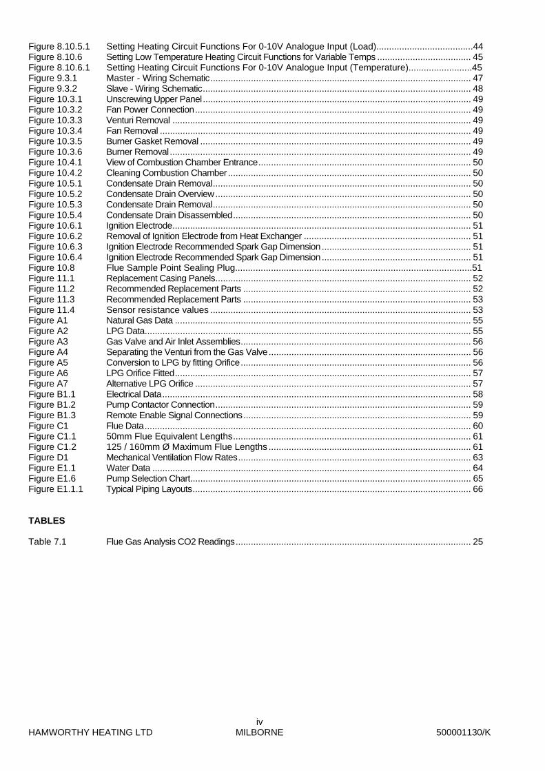
Water Systems Connecting pipework must be self-supporting to avoid stress on the boiler connections. Local unions are recommended in the pipework to facilitate future servicing requirements. Each module is fitted with safety valve rated at 6bar. The valve discharge pipe is routed to the base of the boiler, where it must be piped to discharge via a tundish (not HHL supply) suitably located for ease of visibility. It is strongly recommended that the boiler is fitted to a primary circuit configuration, whereby the primary pump ensures correct flow through all boilers at all times. The Milborne is designed to operate at 20°C ∆T across the flow and return. Should the flow rate drop, the boiler controls will modulate the burner to maintain 20°C ∆T. As a safety precaution, a differential pressure switch is fitted to the boiler heat exchanger to shut the system down in the event of sudden adverse flow conditions. Where using Hamworthy Heating Ltd frame set and pipework kits, assembly of these is detailed in Operation and Maintenance manual 500001156 supplied with kit.
5.3 Water Connections The following connections are provided on each boiler module;
Flow G2½” Male thread. Return G1 ” Male thread.
Condense 18mm dia. Plastic tail
Flow G1 ” Male thread. Safety valve - 22mm copper tail.
●
Milborne 381 / 501
501 Pump specification 70kPa @1980l/hr Flat curve performance, or equivalent to HHL selected Biral pump - see figure E 1.6
● 381 Pump specification 30kPa @1500l/hr Flat curve performance, or equivalent to HHL selected Biral pump - see figure E 1.6
Figure 5.3.2 - Pump performance curve
Figure 5.3.1 - Water Connections - view on base

HAMWORTHY HEATING LTD
20 MILBORNE
500001130/K
5.3 Electrical Connections: The following electrical connections are provided on each module. • Supply: Live, Neutral and Earth. See Section 4.5 for details. • Boiler General Fault Alarm Signal Output • 0-10v Analogue Control Signal Input • Remote on/off Control Input • Upto 3 Circuit Pump Outputs - 1 Primary & 2 Secondary • Safety Interlock Circuit Input • Programmable room thermostat Input • Outside air temperature sensor Input • LPB Bus connections for cascade management 6.0 PRE-COMMISSIONING The following pre-commissioning check must be carried out before the boiler is commissioned. 6.1 Gas Supply. Ensure that gas installation pipework and meter has been soundness tested and purged to IGE/UP/1 or IGE/UP/1A as appropriate. Test and purge certificates should be available for viewing. 6.2 Ventilation Ensure that ventilation and air supply to plantroom is correct. 6.3 Pipework, Valves and Pump Ensure that;
• Pipework and valve arrangement is installed to Hamworthy Heating recommendations.
• Circulating system is full of water, vented and pressurised appropriately.
• Circulation pump is fitted, working and interlocked where required.
• Pipework connections to boiler are fitted correctly.
• All necessary isolation valves are open.
• Condense connections on boiler and flue are connected and piped to drain.
• Heat load is available. 6.4 Flue Ensure that;
• Flue system is correctly designed and installed to suit boilers.
• Flue passages to chimney are clear. 6.5 Electrical Ensure that;
• Electrical connections are correct and isolatable.
• External controls are operational.
WARNING: WHEN THE FRONT COVER IS REMOVED AND THE BOILER IS OPERATIONAL, CARE MUST BE TAKEN WITH ELECTRICAL COMPONENTS AND
ACCESS TO PRIMARY INSULATION.

HAMWORTHY HEATING LTD
21 MILBORNE
500001130/K
Note:- Main Gas Supply Pressures are as follows; Natural Gas - 20mbar LPG Propane - 37.5mbar TO CHECK B 1) Turn off the electrical power and gas supply to the appliance. 2) Connect the manometer assembly to test point (Fitted on the inlet to the gas valve). 3) With A and B closed open C and monitor manometer over a 2 minute period, a rise indicates a leak on valve B. TO CHECK A 1) Open C. 2) Open B to produce the mains gas supply pressure between A and B. 3) Close B. 4) System may be considered sound if over a period of 2 minutes any drop in pressure is less than 0.5 mbar (0.2" wg.). Note:- Allow a manometer stabilisation period of approximately 1 minute before each 2 minute check period. Following soundness tests close valve B and remove manometer connections and tighten test points.
7.0 CHECKS PRIOR TO LIGHTING
IMPORTANT: BEFORE PROCEEDING ENSURE THAT THE PRE-COMMISSIONING CHECKS ON PAGE 20 HAVE BEEN CARRIED OUT AND THE RESULTS SATISFACTORY.
7.1 Boiler Gas System Leak Check Ensure that the appliance manual gas service valve is in the OFF position. Although the boiler receives a gas leak check and gas train component integrity check prior to leaving the factory, transport and installation may have caused disturbance to unions, fittings and gas valve assemblies etc. A procedure guide is given below. Care must be taken not to allow leak detection fluid (if used) on or near any electrical parts or connections. NOTE: When testing 382 / 502 boilers, the test detailed below must be carried out on each module.
Figure 7.1 - Gas System Leak Check Diagram

HAMWORTHY HEATING LTD
22 MILBORNE
500001130/K
7.2 Checks prior to lighting the boiler Note: Refer to Appendix A, Gas Data Tables, for maximum inlet pressure for normal operation. 7.2.1 The Following checks must be made prior to lighting the boiler; 1. Remove the front cover to gain access to the boiler components. The cover is secured with 2 screw on the underside at the left and right hand sides. Once the screws have been removed the cover may be lifted to disengage the retaining clips at the top and removed. Store the front casing panel carefully to prevent damage. Note: Before starting the boiler commissioning procedure verify the following; 2. Ensure that all external controls are not demanding that the boiler commences operation. 3. Make certain that the boiler is configured for the appropriate gas being supplied. Parameter 36 must be checked and set as necessary. When the boiler arrives on site parameter 36 is configured for Natural Gas supply with equivalent flue length less than 15 metres. If using the boiler with a LPG Gas supply or equivalent flue lengths greater than 15 metres, parameter 36 must first be modified in accordance with the table below. Instructions detailing the procedure for modifying parameters are given in Section 8.9 of this manual.
Parameter 36
Description Type of Gas
Range 1-7
Default 1
Specification 1=Natural Gas with equivalent flue length <15m 2=Natural Gas with equivalent flue length >15m 3=LPG with equivalent flue length <15m 4=LPG with equivalent flue length >15m
4. Check that the heating system has been flushed and refilled and that air has been purged from all high points. 5. Ensure that the system isolating valves are in the open position and that the water pressure within the heating system is correct. Minimum pressure 0.5barg. 6. Ensure that circulating pumps have been installed correctly and that the pumps are available for operation. 7. Ensure that the flue ducts are correctly fitted and that they are free from obstruction. Check that the inlet and outlet terminal are located correctly and in accordance with regulations. 8. Ensure that the gas supply has been properly purged and verified for gas soundness. A purge and soundness certificate should be available from the gas pipework installation contractor.
9. Turn on the mains gas supply. Check that sufficient gas pressure is available at the boiler, 17.5mbar Natural Gas, 37.5mbar LPG. 10.Ensure that all electrical connections made to the boiler are correctly sized and installed. Refer to wiring diagrams in Section 9.3. 11 Check that the boiler controls wiring has not been modified. Any modification could lead to boiler failure. 7.2.2 Gas inlet pressure test The gas pressure must be checked at the inlet to the boiler as shown in figure 7.2.2. This is to ensure that the gas pressure is both constant and sufficient to provide full burner output. To verify this the pressure has to be taken as a static and a dynamic reading. The dynamic reading cannot be taken until the boiler has been started - refer to 7.3.3
A maximum difference in gas pressure of 1 mbar must not be exceeded between static and dynamic conditions. The gas pressure measured during these tests must be no less than 17.5 mbar for Natural Gas or 37.5 mbar for LPG.
Gas valve throttle screw
Gas inlet pressure test
point
Gas outlet pressure test
point
Gas Valve offset
adjustment
Fig 7.2.1 Gas valve adjustments

HAMWORTHY HEATING LTD
23 MILBORNE
500001130/K
7.3 Commissioning the Boiler Once the preliminary checks have been completed and the gas inlet pressure has been verified as correct, commissioning of the boiler modules may begin. 1. Insert the combustion analyser probe in the flue at the analysis point shown in figure 7.3.1 2. LPG BOILERS ONLY. Turn the throttle adjustment screw 2 full turns anti-clockwise as indicated in figure 7.3.2
Fig 7.2.2 - Gas Inlet Pressure Test Point
Fig 7.3.2 - Throttle Adjustment 7.4 Initial Lighting Only competent persons registered for working on non-domestic gas appliances should attempt the following operations. Before attempting to commission any boiler, ensure that personnel involved are aware of what action is about to be taken. Record all readings for future reference on relevant commissioning sheet. Allow system to warm up sufficiently to check operation of control thermostat. A combustion check must be taken when first commissioning the boiler. A sampling point is provided in the boiler - refer to fig 7.3.1. NOTE! Care should be exercised when the boiler is firing as the heat exchanger components can achieve temperatures, which could cause injury if touched. Fig 7.4.3 - Starting the Boiler
1. Ensure that all external controls are in demand and that the gas supply to the module is isolated. 2. Switch the main boiler on/off switch located on the underside of the boiler to the on position as indicated in figure 7.4.3. 3. Start the individual boiler module using the on/off switch located on the front of the control panel for the chosen module. Milborne 382 / 502 models have 2 switches on the front of the control panel. It is therefore important to select the switch corresponding to the boiler module being commissioned. See fig 7.4.4 4. Ensure that a number appears in the left indication window of the Master control panel. This number relates to one of the heating circuits. 5. As the gas is isolated, the boiler will make 5 ignition attempts and then go to ignition lockout displaying error code ‘A01’. 6. If the above procedure occurs correctly, open the gas isolation valve, press the reset button (S1) and the fault indication will extinguish. The boiler will commence the ignition sequence and the burner will light. 7. With the boiler firing, the flame signal displayed should be approximately 40μA but not less than 10μA.
Fig 7.3.1 - Flue gas analysis point

HAMWORTHY HEATING LTD
24 MILBORNE
500001130/K
5 Ensure that a number appears in the left indication window of the Master control panel. This number relates to one of the heating circuits.
Demand from domestic hot water circuit or both in operation; Demand from heating circuit 2; 6. Wait for the green indicator LED to illuminate, to indicate that the ignition phase of boiler start-up has commenced. Module reset button
Module fault indication LED, red Module operating indication LED, green
Fig 7.4.4 - Control Panel Modules
Heating circuit indication window
Fig 7.4.5 - Master Control Panel
The operating sequence for the display is as follows; No Demand for heat; Heat Demand for domestic hot water circuit or from heating circuits 1 and 2;
Slow flashing LED = Standby Fast Flashing LED = Ignition phase Steady LED = Flame is present
Note: The ignition sequence is as follows; 1) 5 Seconds of pre-
purge 2) 4 Seconds of post–
purge
Rd
Gn
Fig 7.4.6 7. Run the burner to maximum power. To achieve this press and hold S2 and S4 for 5 seconds. +
S2 S4
After 5 seconds the maximum fan speed can be selected with switch S4. All the fans in the boiler installation will operate now at the maximum speed as programmed at parameter 15; maximum fan speed CH. The first digit of the display will indicate the fan speed. H = maximum speed. The second two digits of the display indicate temperature, e.g. T1 = 80°C
S1
S2
S3
S5
S6
S4

HAMWORTHY HEATING LTD
25 MILBORNE
500001130/K
8. The gas valve throttle setting can now be regulated. This is a based on the flue gas combustion analysis rather than a fixed pressure. Check the CO2 values in accordance with table 7.1. If the CO2 values are incorrect then adjustment must be made by adjusting the gas valve throttle screw. Turning the throttle screw anticlockwise increases the CO2 value. Turning the throttle clockwise decreases the CO2 value. See fig 7.4.8. Note: To increase the gas flow turn the throttle screw anti clockwise, to decrease the gas flow turn the throttle screw clockwise.
12. Ensure that the combustion settings are still correct at maximum output and if necessary repeat steps 7 to 12 until the settings are correct.
Fig 7.4.8 - Throttle Adjustment
9. Allow the boiler to stabilise at maximum power and if necessary readjust the gas flow rate. 10. Reduce the boiler power to minimum by pressing switch S5 on the control panel. The first digit of the display will indicate the fan speed. L = minimum speed.
11. The minimum gas rate can now be set. This again is based on the flue gas analysis rather than a fixed pressure. Check the CO2 values in accordance with table 7.1. If the CO2 values are incorrect then adjustment must be made by adjusting the gas valve offset adjustment screw. See figure 7.4.11. Turning the offset screw anticlockwise decreases the gas flow and decreases the CO2 value. Turning the offset clockwise increases the gas flow and increases the CO2 value. See fig 7.4.11.
Note: To increase the gas flow turn the offset screw clockwise, to decrease the gas flow turn the offset screw anti-clockwise.
Fig 7.4.11 - Gas Valve Offset Adjustment
Gas Maximum Minimum
Natural Gas (model 381 & 501)
CO2 9.2 - 9.4% CO - (80 - 100ppm)
CO2 8.3 - 8.5%
L.P.G. (model 501)
CO2 10.2 - 10.4% CO - (80 - 100ppm)
CO2 8.6 - 8.9%
L.P.G. (model 381)
CO2 10.5 - 11.0% CO - (80 - 100ppm)
CO2 9.0 - 9.5%
Table 7.1: Flue Gas Analysis CO2 Readings
13. The individual boiler module is now commissioned. If there are further modules to be commissioned then switch the commissioned module off using the external thermostatic controls or time clock to ensure correct shutdown. Further modules may now be commissioned individually by following procedure detailed and used for the first module. 14. Once all modules have been commissioned switch all modules to the ‘on’ position and take a dynamic gas inlet pressure test reading to ensure that the gas supply is sufficient for full operating load conditions. This should be taken at all boiler modules to ensure the supply is satisfactory at all boilers.

HAMWORTHY HEATING LTD
26 MILBORNE
500001130/K
8.0 CONTROLS OPERATION 8.1 Overview
The Milborne control system is a self contained , micro-processor based package, controlling and monitoring all safety and functional aspects of the boiler performance and it’s integration with external system controls.
The controls are split into a Master and Slave configuration, with the Master controlling up to 60 slaves. Every boiler module has a slave control and either a 381 / 501 or 382 / 502 boiler must have the Master control. All boiler performance information is accessible and visible through the Master control display.
The Master control will sequence modules with a lead boiler rotation based on hours run. Each Master is supplied with a mixed flow sensor for insertion into the common flow pipework. The sensor must be fitted closest to the heating system pipework, after the last boiler in the cascade. The sequencing can be set in Cascade mode, where individual boilers firing modulate to the maximum rate before switching on the next boiler in the sequence. Alternatively, the sequencing can be set in Unison mode, where individual boilers operate at minimum rate, and collectively modulate to satisfy the demand. Unison mode can realise higher operating efficiencies due to the superior part load performance at low firing rates.
The Master control will manage the operation of two heating circuits plus a dhw circuit. The heating circuits are designated as High temperature and Low temperature, the latter incorporates control outputs for both a pump and a mixing valve, whilst the former and the dhw only have outputs for pump control. An adjustable parameter is provided to enable pump overrun for all three pumps - see section 4.6
All three circuits can be set to operate at different temperatures. The low temperature and dhw circuits having additional optional sensors for control of water temperature. Any unused circuits can be disabled in the parameter settings.
Should there be a malfunction of the Master control, ‘Emergency Mode’ can be activated which will allow the system to operate at a default temperature—see section 8.3.
The Master control will provide summer shutdown, based on outside air temperature measured by the air sensor supplied with each Master. An adjustable parameter is available to select the desired temperature at which the heating circuits operate.
Two stage frost protection is provided by the Master via the outside air temperature. Stage 1 will start the primary pump and stage 2 will start the boilers based on water temperature within the heating circuit.
Weather compensation is available for the heating circuits based on outside air temperature and a common curve. Each circuit can be offset from this curve by setting the maximum and minimum water temperatures in the parameters.
A comprehensive self diagnostic fault identification system is incorporated within the Master control allowing visibility of all boilers in the installation.
8.2 System Design
Hamworthy Heating strongly recommend the use of a primary circuit configuration, with a suitably matched pump (refer to Hamworthy Heating Technical Department for help or assistance if in doubt). This ensures that the individual modules are flow rate protected with the Master controlling the primary circuit pump. Secondary circuits for high temperature constant volume heating, domestic hot water and low temperature variable flow heating, are also controlled from the Master control - refer to figure 8.2.
8.2.1 Primary Circuit
Whenever there is a demand for heat from any or all of the secondary circuits, the primary pump is initiated. A start signal from the Master control connected to the primary pump (P3), via a suitable contactor, will maintain the primary flow until all heat demands are satisfied and the overrun period is timed out. Where twin head pumps are installed a changeover control (not HHL supplied) external to the boiler is required. The temperature set-point of the primary circuit is equivalent to the highest secondary circuit requirement. The temperature sensor provided with the Master boiler must be located between the Master boiler and the low loss header - refer to figure 8.2.1
8.2.2 High Temperature Heating Circuit
Using constant volume flow, the high temperature heating pump (P1) is initiated when there is a demand from the associated room thermostat. The flow temperature to the circuit can be fixed, or directly compensated according to outside air temperature.
When there is a higher temperature demand for dhw, the high temperature pump (P1), is disabled for the duration of the dhw demand.
8.2.3 Low Temperature Heating Circuit
Using a mixing valve and optional flow temperature sensor, the low temperature heating circuit can operate at a lower temperature than the high temperature heating and dhw circuits. The flow temperature to the circuit can be fixed, or compensated using the mixing valve according to the outside air temperature. Regardless of demands on the high temperature or dhw circuits, the low temperature heating circuit operation remains uninterrupted. The low temperature pump (P4) must be started via a double pole relay in conjunction with the room thermostat for the low temperature zone - refer to figure 4.6
8.2.4 Domestic Hot Water Circuit
Using a traditional calorifier, the dhw demand is initiated by the cylinder thermostat (optional HHL sensor is available), starting pump (P2) and adjusting the primary circuit temperature to achieve the desired dhw set-point.

HAMWORTHY HEATING LTD
27 MILBORNE
500001130/K
S1
S2
S3
S6
S4
S5
U2
U3
U4
D4
D5
S1 - Reset S2 - Set / Esc S3 - Set Values S4 - Increase
S5 - Decrease S6 - Prog / Ok U2 - LED Display U3 - LED Display
U4 - LED Display D4 - Power on green LED D5 - Faults display red LED
Figure 8.1.1 - Control Panel - (Master)
Figure 8.1.2 - System overview illustration

HAMWORTHY HEATING LTD
28 MILBORNE
500001130/K
Should the high temperature heating circuit be operating at a lower temperature whilst there is a dhw demand, the high temperature pump (P1) will be disabled to prevent overheating in the heating zone. 8.2.5 Temperature Control Whilst the maximum and minimum settings for the heating circuits are set during commissioning, the User can adjust the operating set-points within these limits via the Master control. 8.2.6 Building Management System Control Where required, the Master control can be set to accept a 0-10v analog control signal. This can be configured for temperature or load control and will control the modulation of the boiler(s). All safety interlocks MUST be wired across the 0-10v circuit using suitable low voltage contact ratings. A 0-10v input signal, can be used to control one temperature circuit only. Either a High or Low Temperature circuit, or Primary circuit, can be controlled under the direction of the BMS signal. Any additional secondary circuits MUST be controlled by the BMS. When using the Master control to manage temperature requirements, a separate time clock for each circuit is required. All external clocks must have volt free switching contacts. When multiple Master boilers are used in the same heating system it is important to ensure a BMS is used to enable each Master Control using 0-10Volt analog signal. Each Master Control requires it’s primary flow temperature sensor locating in a pocket installed in the flow pipework between the boilers and the primary circuit low loss header. When using Hamworthy Frame and Header Kits this pocket is provided. Each Master Control can be configured to accept a 0-10Volt analog signal for either load control or temperature control. The BMS should be configured to provide cascade control of all Master Controls fitted to the same heating system and facilitate load sharing via lead boiler rotation. All ancillary plant (primary pump and secondary circuit pumps/valves) must be controlled via the BMS. The BMS must ensure operation of the primary pump using flow switches before initiating boiler operation. All plant interlocks (pumps, pressurisation units, fire alarms etc) must be configured to prevent boiler operation via the 0-10Volt analog signal.
8.2.6.1 Load Control The Master control translates the analog input and sets the boiler output (%load) accordingly. Set parameter 14=2(for HT circuit) or 22=2(for LT circuit) - see section 8.10.5.1 A 2V input will switch the boiler(s) on at minimum load, 9V input will switch the boiler(s) to maximum load (parameter 15). The load between 2 & 9V is linearly calculated. A switching hysteresis of 0.2V calculates the switch off, hence when the input drops below 1.8V, the boiler(s) will switch off
To prevent boiler overheating, the control can be set to switch off at a pre-determined temperature, regardless of the input voltage (parameter 20 (HT) or 27 (LT)). When using a 0-10v for a Primary circuit, in addition to setting parameter 22=2, set parameter 34=0 to designate pump 3 as the primary pump. This will operate the pump, whenever a demand is applied to the boiler.
8.2.6.2 Temperature Control The Master control translates the analog input and sets the boiler temperature accordingly. Set parameter 14=3(for HT circuit) or 22=3(for LT circuit) - see section 8.10.6.1 A 2V input will set the boiler(s) on at minimum temperature (parameter 18(HT) or 24 (LT)). A 9V input will set the boiler(s) to maximum temperature(parameter 1(HT) or 3 (LT)). The temperature between 2 & 9V is linearly calculated. A switching hysteresis of 0.2V calculates the switch off, hence when the input drops below 1.8V, the boiler(s) will switch off. When using a 0-10v for a Primary circuit, in addition to setting parameter 22=3, set parameter 34=0 to designate pump 3 as the primary pump. This will operate the pump, whenever a demand is applied to the boiler.
Figure 8.2.6.2—Temperature Control
Figure 8.2.6.1 - Load Control

HAMWORTHY HEATING LTD
29 MILBORNE
500001130/K
8.2.7. Connection to temperature control devices Milborne boilers are fitted with a versatile control and management system, which can manage up to three independent circuits operating at different temperatures. Figure 4.6 shows the main devices (temperature sensors, circulators, valves, etc.) which form the three circuits which can be, directly controlled by the boiler controls. Note: Temperature sensors for the secondary circuits are optional extras and must therefore be specified when requesting quotations and placing orders. Programmable room thermostats for low and high temperature heating circuits are 24hr day programmable. 8.2.8 Outside Air Sensor Connection If outside temperature compensation is to be used, the outside air sensor needs to be connected to terminals no. 7 and 8 (figure 4.6). The outside air sensor shall be installed on an outside wall, North or North/East aspect, at a minimum height of 2.5 metres, away from windows, door, and ventilation grilles and flue discharges. Never install the probe in a position exposed to the sun or other forms of radiated heat. Note: the outside sensor is also required to facilitate 2 stage frost protection and Summer Shutdown control. 8.3 Emergency Mode The Milborne boilers incorporate a function which can be activated in the case of a mal-function of the Master control - Emergency Mode. Once enabled, this ensures that the system will operate at a default delivery temperature set by the Manufacturer. 8.3.1 Disconnect the 4 pole connector J14 from the Master pcb - see figure 8.3.1 8.3.2. Set all four J17 switches located on each Slave to the OFF position - see figure 8.3.2 8.3.3. Supply all system pumps with mains via the appropriate contactor hand auto switch 8.3.4. Terminal X1 or Terminal X2 which are part of the cabling of the J14 connector ) must be connected to a 24V DC power supply (see figure 8.3.3) WARNING! If several Milborne boilers are installed in series, one or both of the terminals (X1 or X2) may be connected to the adjacent boilers. If this is the case, supply the free terminal with 24V, for example terminal Xn - see figure 8.3.3.
Slave
Figure 8.3.2
MASTER
Cod. SCHEDA39
BAR
CO
DE
J7
J6
J5
J4
J3
BUS J141 2 3 4MC
J2
T1
J1
PC
R6 R5 R4R3 R2 R1
J10 J8
123
F1 FUSE 3.15A
3
4
1
2
J11
8
J126 5 4 3 2 1 5 4 3 2 1
9 10 11 12 13
1 2 3 4 5 6 7
14
Plug J14
MASTER
Cod. SCHEDA39
BAR
CO
DE
J7
J6
J5
J4
J3
BUS J141 2 3 4MC
J2
T1
J1
PC
R6 R5 R4R3 R2 R1
J10 J8
123
F1 FUSE 3.15A
3
4
1
2
J11
8
J126 5 4 3 2 1 5 4 3 2 1
9 10 11 12 13
1 2 3 4 5 6 7
14
Plug J14
Figure 8.3.1
MASTER
Cod. SCHEDA39
BAR
CO
DE
J7
J6
J5
J4
J3
BUS J141 2 3 4MC
J2
T1
J1
PC
R6 R5 R4R3 R2 R1
J10 J8
123
F1 FUSE 3.15A
3
4
1
2
J11
8
J126 5 4 3 2 1 5 4 3 2 1
9 10 11 12 13
1 2 3 4 5 6 7
14
24Vcc X 1X 2
Plug J14 disconnected1 2 3 4
Figure 8.3.3

HAMWORTHY HEATING LTD
30 MILBORNE
500001130/K
Milborne multiple installation (1 Milborne 382/502 Master with 2 Milborne 382/502 Slaves
Milborne 382/502 Slave Milborne 382/502 Master Milborne 382/502 Slave
Figure 8.4.1 - Milborne Multiple Installation
8.4 Set-up for multiple boiler installations One of the many functions included in Milborne electronics allows for the installation of several modules in series, to create boiler assemblies having an overall power exceeding 75 kW. This type of system requires one single Milborne equipped with a Master control unit, while all other boilers will be equipped with a Slave control unit. The cabling and setting of components, is as follows: 8.4.1 Connect the cabling of the modules making up the series as shown in figure 8.4.1 8.4.2 Every slave control unit making up the system should be identifiable by the single Master control unit by means of an address which is assigned through specific settings on the two series of switches, J10 and J17, located on each Slave in the set. Each slave (one for each burner) needs to be properly configured so that the Master controller can identify its position in the sequence. First the Slave boards need to be divided into 15 blocks. The Master control system can manage a maximum of 15 blocks each made up of 4 Slaves. Eg, If 5 Slave controllers are connected to one Master controller then 2 blocks are required. The first containing 4 Slave controllers and the second just 1. To configure the addresses follow the next procedure. 1. Identify the block that each Slave is to be
assigned, eg block 1… 2… 3… etc. 2. Identify the position that each Slave is to be
assigned in its chosen block, e.g. position 1… 2… 3 etc.
Slave No 3
Slave No 4
Slave No 1
Slave No 2
Slave No 5
Slave No 6
Master
Note: Master controllers are all pre-set as follows; 381/501 - 382/502 Master controllers are always despatched as position 1 and position 2 of block number 1. 382/502 Slave controllers always despatched as position 3 and position 4 of block number 1. Therefore as part of the pre-commissioning checks the settings of all Slave controller block and position switches must be checked. To assist the correct setting of the block and position switches, see figure 8.4.2. Figure 8.4.1 indicates an installation with 1 block and with 1 boiler module. Both addresses are set to 1. 8.4.3 example of installation consisting of 7 boiler modules. When installing 7 boiler modules, ie 7 slaves, two blocks are needed. The first consisting of four boiler modules and the second consisting of three boiler modules. The two blocks must be addressed separately 1 & 2, with block 1 having boiler module addresses 1, 2, 3 & 4 and block 3 having boiler module addresses 1, 2 & 3 - refer to figure 8.4.3

HAMWORTHY HEATING LTD
31 MILBORNE
500001130/K
ON
OFF
Jumpers
1 2
OFF OFF 1
OFF ON 2
ON OFF 3
ON ON 4
Boiler
Module
Slave Address
Jumpers
1 2 3 4
OFF OFF OFF OFF Emergency Code
OFF OFF OFF ON Block 1
OFF OFF ON OFF Block 2
OFF OFF ON ON Block 3
OFF ON OFF OFF Block 4
OFF ON OFF ON Block 5
OFF ON ON OFF Block 6
OFF ON ON ON Block 7
ON OFF OFF OFF Block 8
ON OFF OFF ON Block 9
ON OFF ON OFF Block 10
OFF OFF ON ON Block 11
ON ON OFF OFF Block 12
ON ON OFF ON Block 13
ON ON ON OFF Block 14
ON ON ON ON Block 15
Block Settings
Block Address Slave
Address Block
Address
4 Boiler modules to each block
Figure 8.4.2
1 2 3 4
ON
OFF

HAMWORTHY HEATING LTD
32 MILBORNE
500001130/K
Figure 8.4.3 Example installation consisting of 7 boiler modules in same cascade sequence.
Block 1
1 2
ON
OFF
1 2 3 4
ON
OFF
Boiler module 1
1 2
ON
Block 1
1 2 3 4
ON
OFF
Boiler module 2
Block 1
1 2
ON
OFF
1 2 3 4
ON
OFF
Boiler module 3
1 2
ON
OFF
Boiler module 4
1 2 3 4
ON
OFF
Block 1
Block 2
1 2 3 4 OFF
2
ON
OFF
ON
Boiler module 1
1
Block 2
1 2 3 4 OFF
1 2
ON
OFF
ON
Boiler module 2
Block 2
1 2 3 4 OFF
1 2
ON ON
Boiler module 3

HAMWORTHY HEATING LTD
33 MILBORNE
500001130/K
8.5 Programmable Room Thermostat The high temperature and low temperature heating circuits may have an enhanced level of control by using the 7 day programmable room thermostat. Offering independent switching times for each week day the thermostat offers the flexibility required in buildings with sporadic heating requirements as well as the more traditional occupancy trends. Note: One thermostat is required for each heating circuit. Technical data Power supply = 2 x 1.5V battery Normal temperature range T1 = 5 - 30°C Night set-back range T2 =6°/14°/16°/18°C
Temperature updating = Once/minute Room temperature switching hysteresis = 0.2° - 0.8°C Contacts rating = Max 250V / 5A Internal frost protection = 6°C Minimum setting period = 1 Hour 8.5.1 Locating the thermostat The thermostat should be positioned in the area of the building most critical for comfort. Within this area the thermostat must be positioned away from heat sources such as radiators, sun rays and kitchens. Additionally the thermostat must be located away from sources of draught such as doors, windows and ventilation grilles. All of these can lead to false readings at the thermostat.
INCORRECT LOCATIONS CORRECT LOCATIONS
8.5.2 Mounting the thermostat The thermostat is suitable for wall with rear cable entry. Alternatively the thermostat may also be mounted to a standard electrical back box or round conduit box.
Figure 8.5.2 - Thermostat Mounting
Figure 8.5.1 - Thermostat Location

HAMWORTHY HEATING LTD
34 MILBORNE
500001130/K
Wiring connections Connect the wires from the boiler Master controller to terminal 1 & 2 of the programmable room thermostat. For high temperature heating circuit, terminal 9 at the Master control provides the live and should be wired to terminal 1 at the thermostat. Terminal 10 at
the Master control receives the switch live return and should be wired to terminal 2 at the thermostat. For low temperature heating circuit, terminal 11 at the Master control provides the live and should be wired to terminal 1 at the thermostat. Terminal 12 at the Master control receives the switch live return and should be wired to terminal 2 at the thermostat.
For programming details please refer to the instructions provided with the room thermostat. Alternatively contact Hamworthy Heating Ltd for a copy of instruction manual. 8.6 Master control panel error codes The following tables display the Master control errors messages. These messages relate to faults that can occur within the Master control panel, or from the sensors and circuits connected to the Master control panel. Errors can be divided into two groups: lock-out errors which can be automatically reset (E errors ) and permanent errors (A errors ) which must be reset just by pressing the reset button. 8.6.1 “Error” mode The display starts flashing when a fault occurs. Follow the procedures detailed in figure 8.6.1, to establish the fault code and its relevance. 8.6.2 Controls in permanent lock-out In case of permanent lockout of the burners, it is necessary to press RESET (S1) If you press RESET (S1) while you are in ‘functioning display mode’ all boiler modules will be reset. If you press RESET (S1) while you are displaying the error which caused the permanent lock-out, only the boiler module involved will be reset.
Figure 8.5.3 - Thermostat wiring

HAMWORTHY HEATING LTD
35 MILBORNE
500001130/K
1.
The display starts flashing to signal one or more faults.
2.
Press S4 (+): the display will alternate between the address of the first unit (boiler module) and the first error code. Press S4 again (+) to display all the errors for this unit (boiler module). The error of the successive unit (boiler module) will be visualized one after the other, press S4 (+). Press S5 (-) to display the errors in the oppo-site way, from the last to the first unit (boiler module) (e.g. unit [boiler module] 2 error code E 05. Fault can be either E codes or A codes. If errors derive from the Master, they will be displayed (before the other errors) as U 00 + error code. The Master controller always has addresses U 00.
See error list for codes and re-lated faults
Procedures Display Button Required
3.
Press S2 (SET/ ESC) to exit ‘errors’ and go back to display mode.
Figure 8.6.1
Figure 8.6.3 Master control permanent lock-out errors (A) - manual reset
Display Nr PC Nr Fault Action
A16 10 Internal E2PROM error Reset, check and replace Master board
A18 12 Internal communication error Reset, check and replace Master board

HAMWORTHY HEATING LTD
36 MILBORNE
500001130/K
Figure 8.6.4 Master control blocking errors (E) - auto reset Display Nr PC Nr Fault Action
E02 51 Flow temperature sensor T1 - open circuit Check and replace mixed flow sensor T1
E04 53 DHW temperature sensor T3 - open circuit Check and replace DHW sensor T3
E18 67 Flow temperature sensor T1 - short circuit Check and replace mixed flow sensor T1
E20 69 DHW temperature sensor T3 - short circuit Check and replace DHW sensor T3
E23 28 Internal temperature calibration error Check and replace Master board
E24 29 Internal temperature calibration error Check and replace Master board
E25 0 Internal E2PROM error Check and replace Master board
E25 30 Internal temperature calibration error Check and replace Master board
E26 31 Internal temperature calibration error Check and replace Master board
E32 33 No slaves connected Check the position of the Bi-Polar switches. Check the slave addresses Check slave electrical connections Check and replace Master board Check and replace Slave board
E34 42 Supply frequency error Main frequency is not 50Hz
Figure 8.6.5 Boiler module permanent lock-out errors (A) - manual reset
A01 1 5 failed attempts of starting up Check the gas cock Check for spark and condition of ht. lead Check and replace Slave board
A02 2 Too many failed ignition attempts Check and clean or replace the spark elec-trode. Check and clean or replace the ht lead.
A04 4 Intervention of limit stat > 90°C Check and correct boiler flow rate Check and replace limit thermostat
A05 5 Failed gas valve Faulty connection on gas valve lead
Check and replace the gas valve Check and replace the gas valve cable
A06 6 Internal error Check and replace Slave board
A07 7 Internal error Check and replace Slave board
A08 8 Internal error Check and replace Slave board
A09 9 Supply frequency error Main frequency is not 50Hz
A10 10 Internal error Check and replace Slave board
A11 11 Internal error Reset, check and replace Slave board
A12 12 Internal error Check and replace Slave board
A16 16 Intervention of limit stat > 90°C Check and correct primary flow rate Check and replace limit thermostat
A19 19 Flue sensor error (fan will run at max. speed) Check and clean heat exchanger Check and replace flue sensor
A20 20 Flame detected after closing the gas valve Check and replace the gas valve
A22 22 Internal error Check and replace Slave board
A24 24 Fan error - speed not achieved Check the fan and electrical connections. Replace the fan

HAMWORTHY HEATING LTD
37 MILBORNE
500001130/K
Figure 8.6.6 Boiler module blocking errors (E) - auto reset
8.6.7 Controls Information Controls information can be accessed by pressing the buttons in a prescribed sequence see figure 8.1.1 S1 : Press it in order to unlock the unit when a fault has occurred. S2: To enter into the parameters and monitor mode of each single unit. S3: Displays the running state of the different master circuits S4 & S5: To increase decrease a certain value. S6: To store new values.
8.6.8 Mode Display. The D5 red LED turns on in case a fault occurs causing the permanent lock-out of one boiler module (Reset either the Master or the relevant boiler module to restore normal operation). The D4 green LED displays the presence of communication between the Master and individual boiler modules. The 3 display LED’s U2, U3 and U4 display the following information:
8.7 Users Parameter Adjustments The three following User Parameters can be changed from the function ‘mode display’: ◊ High temperature heating circuit set-point ◊ Water circuit temperature set-point ◊ Low temperature heating circuit set-
point Press S3 to display the listed values: ◊ High temp. heating circuit flow _T (pos. 1) ◊ Domestic Hot Water_T (pos. 2)
◊ Low temp. heating circuit flow_T (pos 4) The following procedure will modify one of the above values: Press S2 to select the desired value, the two right LED digits will flash. Note: if the value does not need changing, press S2 to return to the mode display. If the value needs to be modified, press S4 and S5 until the desired value is displayed. Press S6 to store the value. The chosen value will stop flashing and the display will be restored to the mode display.
Display Nr PC Nr Fault Action
E33 33 Polarity reversed (L~N) Check and correct
E34 34 Reset key error - pressed more than 7 times in 30 mins
If after 40 mins, the error has not cleared, check and replace the Slave board
E35 35 Differential water pressure switch error Check the boiler flow rate and replace the switch if necessary
E36 36 Internal error Check and replace Slave board
E37 37 Flame detection error Check and replace or clean the electrodes
E38 38 Flue sensor - short circuit Check and replace flue sensor
E39 39 Flue sensor - open circuit Check and replace flue sensor
E40 40 Supply frequency error Main frequency is not 50Hz, check supply
E41 41 Internal error Check and replace Slave board
E42 42 Flow temperature sensor - short circuit Check and replace flow sensor
E43 43 Flow temperature sensor - open circuit Check and replace flow sensor
E44 44 Return temperature sensor - short circuit Check and replace return sensor
E45 45 Return temperature sensor - open circuit Check and replace return sensor
E46 46 Flow sensor error—limit temp. exceeded Check the flow rate through the boiler
E47 47 Return sensor error - limit temp. exceeded Check the flow rate through the boiler
E48 48 Flue sensor error - limit temp. exceeded. With this error the fan runs at maximum speed
Check the flow rate through the boiler, clean the heat exchanger, water and gas side
E49 49 Poor or no earth bond Check installation and replace Slave board

HAMWORTHY HEATING LTD
38 MILBORNE
500001130/K
SYSTEM STATUS DISPLAY
No demand of heat and water (the right digits display the flow temperature T1 e.g. T1=30°C)
Request from circuit no. 1 or from the 1st and 2nd circuit at the same time. (the right digits display the flow Temperature T1 e.g. T1=80°C)
Request from water circuit or simultaneous circuit requests. (the right digits display the Flow Temperature T1=80°C) The dot after the no. 1 left digit is flashing.
Request from no.2 circuit. (the right digits display the Flow Temperature T1 e.g. T1=80°C)
The external probe is not connected, the compensated function has been selected (parameters 14 & 22). In this configuration the pump will run continuously. Set parameters 14 & 22 to (0) - constant temperature.
Figure 8.6.8
8.8 Changing Operating Temperature Set-Points. Refer to figure 8.7.1. If no variations occur within 10secs after pressing S2 at step 3, (because the desired value corresponds with the set value) the display will be restored to the mode display. If after pressing + and - , at step 4, no operation is carried out, after 1 minute the display shall be restored to the mode display. The new selected value shall not be restored. 8.9 Monitor Mode Press S2, to enter into the Monitor mode and display the running status of each single boiler module (from address 1 to 60) - see figure 8.8.1.
Step Procedures Button Required Display
1. Mode display, there is no demand from any circuit with the flow temperature at 80°C
2.
Press S3 to enter into the setting display, press it again and set 6 on the first digit to display the current Low Temp. circuit set-point - 50°C.
3. Press S2 (set/esc) to select the chosen value. The two right LED digits will flash.
4. Press S5 (-) to change the setpoint to the desired value - 40°C. The two right LED digits will continue to flash.
5. Press S6 (Prog/OK) to store the new value. The two right LED digits will stop flashing. After 3 secs., the display will return to the mode display with the new set value.
Figure 8.7.1 - procedure for adjusting Low Temperature Heating circuit

HAMWORTHY HEATING LTD
39 MILBORNE
500001130/K
Step Procedures Button Required Display
1. Mode display is reading high temperature heating circuit flow at 80°C
2.
Press S2 (SET/ESC), for 5 sec. The display shows that it is possible to read the values, or the functioning mode of boiler module 1.
3. Press S4 (+) or S5 (-) to scroll the desired boiler module (e.g. for boiler module 19)
4. Press S3 to display the 1st value for the selected boiler module. Press the same button, S3, to display the following values (e.g. 1st value, flow temperature reading)
5. Press S2 to exit from the monitor mode (SET/ESC). If no operations are carried out for 5 minutes, the display shall be restored to the mode display.
Figure 8.8.1 - procedure for accessing the Monitor Mode
Pos. Value Display
1. High temp. circuit flow temperature T1 - 70°C
2.
Domestic hot water storage temperature T3 - 50°C
3. External temperature T4 - 60°C
4. 2nd circuit or low temp circuit flow temperature T6 - 50°C
5. 1st circuit or high temp circuit room thermostat Ta1 closed (of) or open (on) or
6. 2nd circuit or low temp circuit room thermostat Ta2 closed (of) or open (on) or
7. Analogue input 0~10v - 5.5v or 10v or
8. Mixing valve status - closed
9. 1st circuit or high temp. circuit pump function status (of) or (on) or
10.
Domestic hot water circuit pump function status (of) or (on) or
11. Main pump function status (of) or (on)
Figure 8.8.2 - display value sequence

HAMWORTHY HEATING LTD
40 MILBORNE
500001130/K
8.9.1 Programming Mode (restricted to Authorized Personnel and the Manufacturer only) A Password is needed to modify these parameters. Only authorised personnel can enter the password and then modify the user and service parameters.
Step Procedures Button Required Display
1. Mode display is reading high temperature circuit at flow temperature at 80°C
2.
Press S2 (SET/ESC) followed by S6 (Prog/OK). After 5 seconds the second and third digit will start flashing.
3. Use S4 (+) and S5 (-) to enter the second figure of the password on the right hand digit (e.g. password = x2)
4. Press S6 (Prog/OK) and store the second figure of the password.
5. Use S4 (+) and S5 (-) to enter the first figure of the password on the central digit. (e.g. password = 22)
6. Press S6 (Prog/OK) to store the password. If the password is wrong, the display will return to mode position
7 Use S4 (+) and S5 (-) to scroll all password protected parameter addresses. Press S2 (Set/Esc) to select the parameters for modification. Parameter address and its respective value will alternate on the display
See parameter list for address
and range settings
8. Use S4 (+) and S5 (-) to change the value of the selected parameter. Every time one of these keys is pressed the alternating of the parameter address and the value is stopped for 5 seconds and only the value is shown.
9. Press S6 (Prog/OK) to accept and store the new value. The display will return to the display at step 6. To check and alter further parameters return to step 7 and follow through.
Figure 8.9.1 - programming parameters

HAMWORTHY HEATING LTD
41 MILBORNE
500001130/K
8.9.2 Combustion test parameters Using the function ‘ Combustion Test’, it is possible to generate a request from the 1st circuit or high temperature heating circuit, to enable the combustion to be checked at maximum and minimum fan speeds and any adjustments made to the calibration of the gas valve. The main pump and high temperature heating circuit are activated. All combustion fans will be activated. If a module or slave is electrically isolated by the ‘On/Off switch (see figure 7.4.3) all other fans will run. To access the ‘combustion test’ display screen
Step Procedures Button Required Display
1. Press S2 (SET/ESC) and S4 (+) for 5 seconds. All system fans will operate at the selected speed.
2.
The maximum and minimum speeds can be selected by pressing S4 (+) for maximum (H)and S5 (-) for minimum (L).
3. The other two digits show the flow temperature at maximum or minimum firing rate. Press S6(OK) to exit ‘test mode’ and return to the display.
Figure 8.9.2 - combustion test parameters

HAMWORTHY HEATING LTD
42 MILBORNE
500001130/K
8.10 Programming Procedure 8.10.1 Master control primary functions - must be set in all instances
Parameter Description Setting procedure
Heating engineer adjustable parameters – code protected P.33 Sequence control mode Set to 0 – Cascade control mode. Minimum number of modules
firing Set to 1 – Unison control mode. Maximum number of modules firing
P.34 Pump 3 priority Ensure setting = ‘0’ for primary pump control
P.35 Frost protection Set to the external air temperature at which frost protection is started, -30°C to +15°C
P.36 Gas type Set to 1 – Nat Gas with < 15m flue length Set to 2 – Nat Gas with > 15m flue length Set to 3 – L.P.G. with < 15m flue length Set to 4 – L.P.G. with > 15m flue length Set to 5 – Towns Gas (Channel Islands)
P.39 External air sensor calibration
Use to correct external air sensor reading, -30°C to +30°C. Eg If air temp = 25°C and sensor reading = 20°C set to +5°C
P.41 Parameter reset Set to 1 to reset all parameter values to factory settings. Resets all parameters except P.36 for safety reasons. Set to 0 to make new parameter changes
8.10.2 Setting DHW functions
End user adjustable parameters P.2 Domestic hot water circuit set
-point Set to required operating temperature. Limited by setting at parameter 8.
Heating engineer adjustable parameters – code protected P.6 Domestic hot water circuit
type Set to 0 for DHW disabled Set to 1 for plate h/ex with NTC sensor Set to 2 for calorifier with NTC sensor Set to 5 for Plate h/ex with thermostat Set to 6 for calorifier with thermostat
P.8 Domestic hot water circuit upper limit
Limits the end users set-point adjustment available at parameter 2. Max 70°C
P.9 Domestic hot water circuit priority
Set to 0 or 1 for shared priority with heating circuits Set to 2 to prioritise domestic hot water
P.10 Domestic hot water primary set-point
Set the temperature difference between the required primary temperature and the domestic hot water set-point at parameter 2. Eg If P.2 = 60°C add 20°C, = 80°C
P.11 Domestic hot water circuit hysteresis off
Sets the temperature at which the burner will stop after reaching set-point at parameter 2. Eg. For 60°C set-point. Setting to 1 will stop the DHW pump at 61°C
P.12 Domestic hot water circuit hysteresis on
Sets the temperature at which the burner will re-start after reaching set-point at parameter 2. Eg. For 60°C set-point. Setting to 2 will start the DHW pump at 58°C
Circuit priority Parameter P.9 - Prioritising the domestic hot water circuit allows the boiler management system to provide that circuit with maximum available power at all times there is a hot water demand. The priority method may reduce the power available to other circuits if there is a high demand in the prioritised circuit and the boiler sizing is lean. If all circuits are required to operate without interruption the priority should be set to shared, ie setting ‘0’ or ‘1’.

HAMWORTHY HEATING LTD
43 MILBORNE
500001130/K
8.10.3 Setting high temperature heating circuit functions for constant temperature
Parameter Description Setting procedure
End user adjustable parameters P.1 High temperature circuit set-
point Set to required operating temperature. Limited by setting at parameters 17 & 18.
Heating engineer adjustable parameters – code protected P.14 High temperature circuit type Set to 0 for constant flow temperature
P.16 Heating circuit priority Set to 0 for shared priority Set to 1 for high circuit priority Set to 2 for low circuit priority
P.17 High temperature circuit upper limit
Limits the end users set-point adjustment available at parameter 1. Max 80°C
P.18 High temperature circuit lower limit
Limits the end users set-point adjustment available at parameter 1. Min 10°C
P.19 High temperature circuit hysteresis on
Sets the temperature at which the burner will re-start after reaching set-point at parameter 1. Eg. For 80°C set-point. Setting to 7 will start the burner at 73°C
P.20 High temperature circuit hysteresis off
Sets the temperature at which the burner will stop after reaching set-point at parameter 1. Eg. For 80°C set-point. Setting to 1 will stop the burner at 81°C
Circuit priority Parameter P.16 - Prioritising one heating circuit over the other, allows the boiler management system to provide that circuit with maximum available power at all times there is a heating demand. The priority method may reduce the power available to other circuits if there is a high demand in the prioritised circuit and the boiler sizing is lean. If all circuits are required to operate without interruption the priority should be set to shared, ie setting ‘0’.
8.10.4 Setting low temperature heating circuit functions for constant temperature
End user adjustable parameters P.3 Low temperature circuit set-
point Set to required operating temperature. Limited by setting at parameters 23 & 24
Heating engineer adjustable parameters – code protected P.22 Low temperature circuit type Set to 0 for constant flow temperature
P.23 Low temperature circuit upper limit
Limits the end users set-point adjustment available at parameter 3. Max 70°C
P.24 Low temperature circuit lower limit
Limits the end users set-point adjustment available at parameter 3. Min 10°C
P.26 Low temperature circuit hysteresis on
Sets the temperature at which the burner will re-start after reaching set-point at parameter 3. Eg. For 50°C set-point. Setting to 7 will re-start the burner at 43°C
P.27 High temperature circuit hysteresis off
Sets the temperature at which the burner will stop after reaching set-point at parameter 3. Eg. For 50°C set-point. Setting to 1 will stop the burner at 51°C
P.28 Mixing valve opening period Set time taken for mixing valve to open from fully closed position. Eg 5 secs. Max 255 secs
P.29 Mixing valve closing period Set time taken for mixing valve to close from fully open position. Eg 7 sec. Max 255 secs
P.30 Mixing valve static period Set time mixing valve is to remain static after moving. Eg 5 secs. Max 255 secs

HAMWORTHY HEATING LTD
44 MILBORNE
500001130/K
8.10.5 Setting high temperature heating circuit functions for compensated (variable) temperature
Parameter Description Setting procedure
End user adjustable parameters P.1 High temperature circuit set-
point Set to required operating temperature. Limited by setting at parameters 17 & 18.
Heating engineer adjustable parameters – code protected P.14 High temperature circuit type Set to 1 for compensated flow temperature
P.16 Heating circuit priority Set to 0 for shared priority Set to 1 for high circuit priority Set to 2 for low circuit priority
P.17 High temperature circuit upper limit
Limits the end users set-point adjustment available at parameter 1. Max 80°C Sets max flow temperature at the minimum external air temperature set at parameter 37
P.18 High temperature circuit lower limit
Limits the end users set-point adjustment available at parameter 1. Min 10°C Sets min flow temperature at the maximum external air temperature set at parameter 38
P.19 High temperature circuit hysteresis on
Sets the temperature at which the burner will re-start after reaching set-point at parameter 1. Eg. @ 80°C set-point. Setting to 7 will re-start the burner at 73°C
P.20 High temperature circuit hysteresis off
Sets the temperature at which the burner will stop after reaching set-point at parameter 1. Eg. For 80°C set-point. Setting to 1 will stop the burner at 81°C
P.37 Compensation curve min external air temp setting
Set for external air temperature at which the maximum flow temperature set in parameter 17 is required. Eg -1°C Also sets external air temperature limits for low temperature heating circuit
P.38 Compensation curve max external air temp setting
Set for external air temperature at which the minimum flow temperature set in parameter 18 is required. Eg +18°C Also sets external air temperature limits for low temperature heating circuit
Circuit priority Parameter P.16 - Prioritising one heating circuit over the other, allows the boiler management system to provide that circuit with maximum available power at all times there is a heating demand. The priority method may reduce the power available to other circuits if there is a high demand in the prioritised circuit and the boiler sizing is lean. If all circuits are required to operate without interruption the priority should be set to shared, ie setting ‘0’.
8.10.5 .1 Setting heating circuit functions for 0-10v analog input (LOAD)
P.14 High temperature circuit type Set to 2 for BMS 0-10v load based High temperature circuit
P.15 Heating circuit maximum load Sets the heating circuit maximum load (1-255) Eg. 230 equates to 90% load
P.19 High temperature circuit hysteresis on
Sets the temperature at which the burner will re-start after reaching set-point at parameter 1. Eg. For 80°C set-point. Setting to 7 will re-start the burner at 73°C
P.20 High temperature circuit hysteresis off
Sets the temperature at which the burner will stop after reaching set-point at parameter 1. Eg. For 80°C set-point. Setting to 1 will stop the burner at 81°C
P.26 Low temperature circuit hysteresis on
As 19 above. Eg. For 40°C set-point. Setting to 7 will re-start the burner at 33°C
P.27 Low temperature circuit hysteresis off
As 20 above. Eg. For 40°C set-point. Setting to 1 will stop the burner at 41°C
P.22 Low temperature circuit type Set to 2 for BMS 0-10v load based Low temperature circuit

HAMWORTHY HEATING LTD
45 MILBORNE
500001130/K
8.10.6 Setting low temperature heating circuit functions for compensated (variable) temperature
Parameter Description Setting procedure
End user adjustable parameters P.3 Low temperature circuit set-
point Set to required operating temperature. Limited by settings at parameters 23 & 24.
Heating engineer adjustable parameters – code protected P.22 Low temperature circuit type Set to 1 for compensated flow temperature
P.23 Low temperature circuit upper limit
Limits the end users set-point adjustment available at parameter 3. Max 70°C Sets max flow temperature at the minimum external air temperature set at parameter 37
P.24 Low temperature circuit lower limit
Limits the end users set-point adjustment available at parameter 3. Min 10°C Sets min flow temperature at the maximum external air temperature set at parameter 38
P.26 Low temperature circuit hysteresis on
Sets the temperature at which the burner will re-start after reaching set-point at parameter 3. Eg. For 50°C set-point. Setting to 7 will re-start the burner at 43°C
P.27 High temperature circuit hysteresis off
Sets the temperature at which the burner will stop after reaching set-point at parameter 3. Eg. For 50°C set-point. Setting to 1 will stop the burner at 51°C
P.28 Mixing valve opening period Set time taken for mixing valve to open from fully closed position. Eg 5 secs. Max 255 secs
P.29 Mixing valve closing period Set time taken for mixing valve to close from fully open position. Eg 7 secs. Max 255 secs
P.30 Mixing valve static period Set time mixing valve is to remain static after moving. Eg 5 secs. Max 255 secs
P.37 Compensation curve min external air temp setting
Set for external air temperature at which the maximum flow temperature set in parameter 23 is required. Eg -1°C Also sets external air temperature limits for high temperature heating circuit
P.38 Compensation curve max external air temp setting
Set for external air temperature at which the minimum flow temperature set in parameter 24 is required. Eg +18°C Also sets external air temperature limits for high temperature heating circuit
8.10.6.1 Setting heating circuit functions for 0-10v analog input (TEMPERATURE)
P.14 High temperature circuit type Set to 3 for BMS 0-10v temperature based P.18 High temperature circuit
lower limit Limits the end users set-point adjustment available at parameter 1. Min 10°C - Max 50°C
P.19 High temperature circuit hysteresis on
Sets the temperature at which the burner will re-start after reaching set-point at parameter 1. Eg. For 80°C set-point. Setting to 7 will re-start the burner at 73°C
P.20 High temperature circuit hysteresis off
Sets the temperature at which the burner will stop after reaching set-point at parameter 1. Eg. For 80°C set-point. Setting to 1 will stop the burner at 81°C
P.26 Low temperature circuit hysteresis on
As 19 above. Eg. For 40°C set-point. Setting to 7 will re-start the burner at 33°C
P.27 Low temperature circuit hysteresis off
As 20 above. Eg. For 40°C set-point. Setting to 1 will stop the burner at 41°C
P.24 Low temperature circuit lower limit
Limits the end users set-point adjustment available at parameter 3. Min 10°C - Max 25°C
P.22 Low temperature circuit type Set to 3 for BMS 0-10v temp. based Low temperature circuit

HAMWORTHY HEATING LTD
46 MILBORNE
500001130/K
9.0 FAULT FINDING The Milborne boiler is equipped with full self-diagnostic fault indication, with faults allocated a code, which is displayed (flashes) on the screen - refer to section 8.6 The common fault codes are detailed in section 8.6. Fault codes not detailed in this manual should only be investigated by an Engineer. Should a fault code appear which cannot be reset, or a fault code repeatedly occurs, contact Hamworthy Heating for assistance. Do not continue to operate or use the boiler as this may cause damage to the controls. 9.1 Safety Features 9.1.1 Temperature Limit Thermostat The electronic control thermostat has several safety levels built in such that controlled shutdown should occur before the limit thermostat is activated requiring manual reset. Should these safety levels be overridden (say external pump overrun failure after shutdown, or operation of the module on/off switch during operation), the temperature limit thermostat will trip initiating a boiler lockout, preventing the boiler from firing. An error code will be indicated on the display (A17) which will require the control to be reset (S1), once the boiler has cooled sufficiently. An investigation should be carried out to ascertain the reason for the overheating. An obvious reason would be low or no flow through the heat exchanger. 9.1.2 Flame Sensing The flame is under constant supervision by the burner control. This is accomplished by measuring the flame’s ability to rectify an AC current. If the flame diminishes for whatever reason, the rectified current drops until such that it is below the control threshold (2μA) and the boiler will shut down and will perform up to 5 ignition attempts. If the boiler has failed to light it will go to lockout an error code will be indicated on the display (A01) which will require the control to be reset (S1). If the boiler continues to lockout, an investigation must be made to ascertain the cause—refer to section 9.3 9.2 Fault Finding Procedures General error codes are detailed in section 8.5 to assist with general fault finding. If the boiler still cannot operate satisfactorily after following the instructions, consult Hamworthy Heating for assistance. 9.3 Possilbe Causes of Boiler Lockout 1) Ignition failure due to faulty igniter. 2) Ignition failure due to faulty gas valve. 3) No or low gas supply pressure. 4) No ignition due to faulty controller. 5) Ignition failure due to faulty flame probe or sensing circuit. 10.0 SERVICING A competent person registered for working on non domestic gas appliances should check and ensure that the flue, its support and terminal, the ventilation to the boiler house, safety valve, condensate trap, drain, water filter if fitted, pressure gauge etc., are in a serviceable and working condition, and still comply with the relevant standards and codes of practice - see Section 4 & Appendices 10.1 Regular servicing is recommended, preferably by a Hamworthy appointed person, and at least annually, to ensure trouble free operation. For the Milborne boiler, Hamworthy would recommend an additional 6 monthly examination following commissioning, acknowledging site conditions and running hours. Although cleaning of flueways may not be necessary on a yearly basis inspection of the flueways must be undertaken annually and it is important that all controls and safety features are checked for correct operation. NOTE! Measuring flue gas CO2 and gas temperatures will give an indication of the state of the boiler flueways and waterways. Results should be compared with previously measured values to establish possible loss of efficiency. Should remedial work be carried out on a module within a bank of boilers, then the non-firing module must be electrically isolated so as to prevent accidental operation., in the event that the installation is required for ongoing heating requirements. 10.2 The procedure detailed relates to a single module and must be carried out on all modules within a bank of boilers. Before servicing the boiler, the following procedure must be carried out: -

HAMWORTHY HEATING LTD
47 MILBORNE
500001130/K
Figure 9.3.1 - Milborne 382 / 502 - Wiring Schematic
CU
RR
ENT
WIR
ING
SC
HEM
ATI
C
PREV
IOU
S W
IRIN
G S
CH
EMA
TIC
MA
IN E
ARTH
ING
BLO
CK
LIV
E 23
0V A
.C.
NEU
TRAL
230
V A.
C.
GV
230V
- 50
Hz
BOIL
ER
ISO
LATI
ON
SW
ITC
H N L GV
N L GV
GR
OUN
D
NEU
TRA
L
LIVE
GV
GV
6 5 4 3 2 1 3 2 1 2 1
1 2 3 4 5 6 7 8
28 27 26 25 24 23 22 21 20 19 18
1 2 3 4 5 6 7 817
1615
1413
1211
109
98
76
54
32
1
0 OFF
ON
AN
ALO
GU
E
INPU
T
MAS
TER
Cod
. SC
HEDA
39
BARCODE
J7 J6 J5 J4J3
BU
S J1
41
23
4M
CJ2
T1
J1 PC
R6R5
R4R3
R2R1
J10
J8
1 2 3
F1FU
SE 3
.15A
3 4
1 2
J11
8
GR
OU
ND
J12
SLA
VE M
OD
ULE
No.
2
27-2
8. P
DH
W P
UM
P25
-26.
P H
IGH
PUM
P23
-24.
P L
OW
PU
MP
20-2
2. V
MIX
VAL
VE18
-19.
FA
ULT
LIG
HT
1-2.
PR
IM F
LOW
SEN
SO
R3-
4. D
HW S
ENSO
R5-
6. L
T FL
OW
SEN
SOR
7-8.
EXT
SE
NSO
R
17. 2
4V R
EMO
TE16
. CO
MM
ON
15. E
BUS
REM
OTE
13-1
4. 0
-10V
AN
ALO
GU
E IN
PUT
11-1
2. L
T RO
OM
STA
T9-
10. H
T RO
OM
STA
T
LPB
BUS
CON
NEC
TIO
N T
O A
DD
ITIO
NAL
BOIL
ERS
IN M
ODU
LAR
APP
LIC
ATIO
NS
65
43
21
54
32
19
1011
1213
12
34
56
7
NE
UTR
AL
LIVE
EAR
TH
SLA
VE
MO
DUL
EN
o. 1
14
-+
MA
IN E
ARTH
ING
BLO
CK
LIVE
230
V A.
C.
NEU
TRAL
230
V A.
C.
NEU
TRAL
LIVE
GV
230V
- 50
Hz
BOIL
ER IS
OLA
TIO
N S
WIT
CH N L G
V
N L GV
Gro
und
Neu
tral
Live
GV
GV
6 5 4 3 2 1 3 2 1 2 1
1 2 3 4 5 6 7 8
28 27 26 25 24 23 22 21 20 19 18
1 2 3 4 5 6 7 817
1615
1413
1211
109
98
76
54
32
1
0 OFF
ON
AN
ALO
GU
E
IN
PUT
MAS
TER
BARCODE
J7 J6 J5 J4J3
BUS
J14
12
34
MCJ2
T1
J1 PC
R6R5
R4R3
R2R1
J10
J9
1 2 3
F1FU
SE
3.15
A
J12
J11
1
n
J82
34
56
78
91
23
45
67
8
4G
RO
UN
D
61
23
45
12
31
2
EART
H
SLAV
E M
OD
ULE
No. 2
27-2
8. P
DH
W P
UM
P25
-26.
P H
IGH
PU
MP
23-2
4. P
LO
W P
UM
P20
-22.
V M
IX V
ALVE
18-1
9. F
AULT
LIG
HT
1-2.
PR
IM F
LOW
SE
NSO
R3-
4. D
HW
SEN
SOR
5-6.
LT
FLO
W S
ENS
OR
7-8.
EXT
SEN
SOR
17. 2
4V R
EMO
TE16
. CO
MM
ON
15. E
BUS
REM
OTE
13-1
4. 0
-10V
AN
ALO
GUE
INPU
T11
-12.
LT
RO
OM
STA
T9-
10. H
T R
OO
M S
TAT
LPB
BUS
CON
NEC
TIO
N T
O A
DD
ITIO
NAL
BOIL
ERS
IN M
ODU
LAR
APP
LIC
ATIO
NS
SLA
VE M
OD
ULE
No.
1
-+

HAMWORTHY HEATING LTD
48 MILBORNE
500001130/K
Figure 9.3.2 - Milborne 382 / 502 Slave - Wiring
Sup
ply
tom
aste
rc
ontr
ol
gyE
AR
TH
NEU
TR
AL
LIV
E
Boil
erIs
ola
tion
Swit
ch
Mai
n Su
pply
Ma
in e
arth
ing
blo
c k
Flam
e P
rob
eM
ain
Mod
ule
Eart
h
T1
J7 13
J8Fu
se
4A
F1
J6
J14
J15
Mod
ule
ON
/OFF
Sw
itc
h
LN
LN
1
5
2 3 4 5 6
6
1234
7
56
8
13 24 5 3 24
J2 J1
J11 J4
Mo
tori
sed
Val
ve-R
etu
rn
Ga
sV
alve
The
rmos
tat
Lim
it
13 24
J1
2
5
Liv
eIn
pu
t Sen
s. H
all
Se
ns. H
all
Se
ns. H
all
Ne
utra
l
Fan
1011 9
Flo
w T
emp.
Sen
so
r
Sen
so
rR
etur
n T
emp.
Ret
urn
Tem
p.S
ens
or
WD
Sla
ve M
odul
e No
. 1
T3
PC/
J5
J10
J17
Mai
nJ
9
J16
12
BU
S1
Mo
dule
ON
/OF
FS
wit
ch
Inpu
t Se
ns. H
all
1
1
PC/J
5
J17
J10
J11
J9
BU
S1
Mai
nJ1
6
T3
12
Neu
tral
2
9
34
J4
5
1011
Live
Sens
. Ha
llSe
ns.
Hall
1234
Ma
in M
odul
e E
arth
J12
WDT1
Sla
ve M
odu
le N
o. 2
3 245
Fla
me
Pro
be
13
J7J8
F1Fu
se 4
A
J2
6
J1
2345
78
64 5
6
J14 1 2 3
J15
5
J6
LN
LN
Flo
w T
emp.
Sen
sor
Sen
sor
Ret
urn
Te
mp.
Ret
urn
Te
mp.
Sen
sor
Fan
Mot
ori
sed
Val
ve-R
etur
n
Gas
Val
ve
The
rmos
tat
Lim
it
LPB
plu
s c
onn
ectio
nto
add
ition
al b
oile
rs in
mod
ular
app
licat
ions
SLA
VE
WIR
ING
13
Sw
itch
Pre
ssur
eP
ress
ure
Sw
itch
13

HAMWORTHY HEATING LTD
49 MILBORNE
500001130/K
WARNING: Isolate the electrical supply using the switch on the base of the control panel (see figure 7.4.3) and turn off the gas supply to the boiler module being serviced. 10.3 Cleaning the burner In order to clean the burner, simply dust it with a bristle brush, wash it with water and blow compressed air through it from the inside outwards. To carry-out this operation, remove it from the heat exchanger in the following manner: Unscrew the upper panel and remove it as shown in figure 10.3.1
Upper panel fixing screws
Figure 10.3.1
Figure 10.3.2
Disconnect the power supply connector of the fan as shown in figure 10.3.2
Fan power supply connector
Figure 10.3.3
Removal of venturi securing screws
Unfasten the three screws on the Venturi pipe to disconnect it from the fan as shown in figure 10.3.3
Figure 10.3.4
Unscrew the 4 nuts locking the flange onto the burner head and remove the fan as shown in figure 10.3.4
Figure 10.3.5
Figure 10.3.6
Remove the gasket and slide the burner upwards and out of the exchanger as shown in figure 10.3.5 and figure 10.3.6
Caution! After cleaning the burner, new gaskets must be used for the burner and air-gas manifold flange.
Burner gasket
Burner
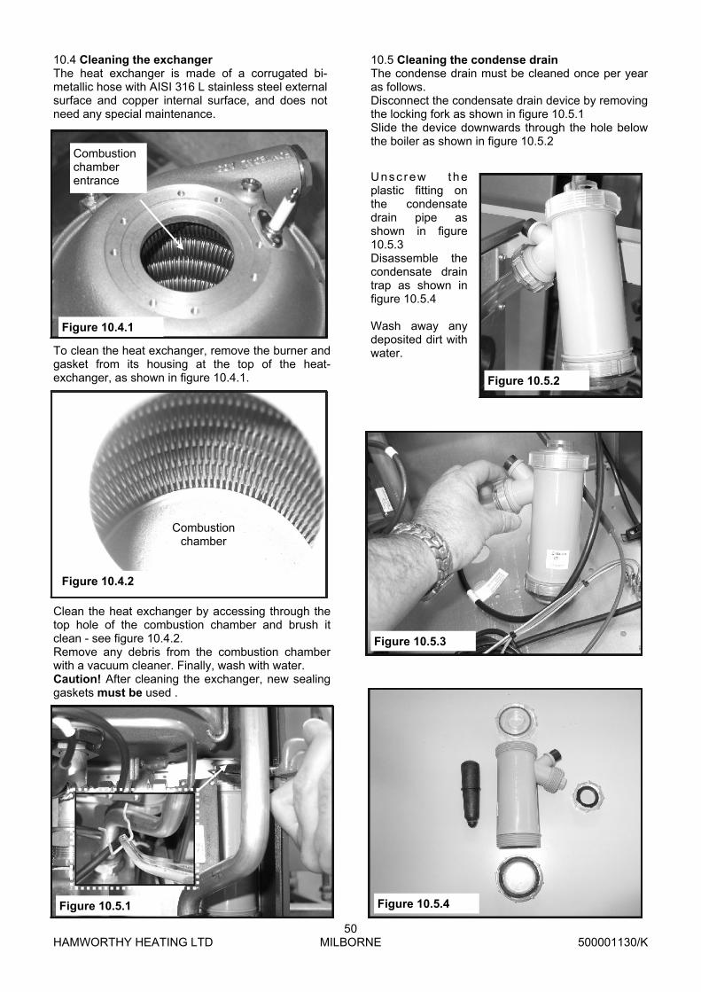
HAMWORTHY HEATING LTD
50 MILBORNE
500001130/K
10.4 Cleaning the exchanger The heat exchanger is made of a corrugated bi-metallic hose with AISI 316 L stainless steel external surface and copper internal surface, and does not need any special maintenance.
Figure 10.4.1
Combustion chamber entrance
To clean the heat exchanger, remove the burner and gasket from its housing at the top of the heat-exchanger, as shown in figure 10.4.1.
Figure 10.4.2
Clean the heat exchanger by accessing through the top hole of the combustion chamber and brush it clean - see figure 10.4.2. Remove any debris from the combustion chamber with a vacuum cleaner. Finally, wash with water. Caution! After cleaning the exchanger, new sealing gaskets must be used .
Combustion chamber
Figure 10.5.1
Figure 10.5.2
Figure 10.5.3
10.5 Cleaning the condense drain The condense drain must be cleaned once per year as follows. Disconnect the condensate drain device by removing the locking fork as shown in figure 10.5.1 Slide the device downwards through the hole below the boiler as shown in figure 10.5.2
Figure 10.5.4
Unsc rew the plastic fitting on the condensate drain pipe as shown in figure 10.5.3 Disassemble the condensate drain trap as shown in figure 10.5.4 Wash away any deposited dirt with water.

HAMWORTHY HEATING LTD
51 MILBORNE
500001130/K
10.6 Cleaning the ignition electrode The ignition electrode is used to create a high-voltage spark and also to sense the flame. This component requires annual maintenance to remove any layer of oxide which may have built-up on the wire. Check whether the electrode wire has any earth current leakage and make sure that the cap is not oxidized. In case of oxidation, replace the spark plug and its cap with new ones - see figure 10.6.1
Figure 10.6.1
Figure 10.6.2
Loosen the fixing screws of the ignition electrode bracket - see figure 10.6.1. Remove the electrode from the heat exchanger - see figure 10.6.2. Check the condition of the electrode and remove any oxide present with abrasive paper, or replace the electrode. If the electrode is replaced, a new gasket MUST be fitted. Accurately check the distance between the electrode wires - see figure 10.6.3. & 10.6.4. NOTE: Two types of electrode have been used and both are interchangeable. The distance should be 3 - 5 mm; 10.7 Reassembly - having carried out the detailed servicing procedure, re-assemble all components, having fitted replacement gaskets where required. Check all gas connections are tightened securely before opening the gas service cock. Re-connect
Distance between wires 3 - 5mm Figure 10.6.3
Gasket
electrical connections. Switch on the electrical supply to the module - see figure 7.4.3, and re-light the boiler following the procedure detailed in section 7.4. Take combustion readings and compare with those previously taken—see section 7.4 Ensure that no gas leaks are evident from gas connections. Check temperature settings and adjust if necessary
10.8 Flue sample point sealing plug The plug is provided to allow set-up and adjustment, if necessary, of combustion during maintenance and commissioning of the boiler THE PLUG MUST BE REPLACED FINGER TIGHT ONLY!
Figure 10.6.4 Distance between wires 3 - 5mm
Figure 10.8

HAMWORTHY HEATING LTD
52 MILBORNE
500001130/K
11.0 RECOMMENDED SPARES Please Note:- To ensure the correct spare parts are despatched by our spares department, it is imperative that the complete Boiler/Module/Control Panel Serial Numbers are given. The Boiler and Module Serial Numbers are located on the Data Plates affixed to the combustion chamber front panel. The Electrical Serial Number is located inside the Control panel on the maximum power rating label. These numbers MUST be quoted when ordering spare parts.
Figure 11.1
1
2
3
4
5
6
7
8
9
10
11
12
13
Figure 11.2

HAMWORTHY HEATING LTD
53 MILBORNE
500001130/K
Figure 11.3
14
15
16
17
18
19
20
21
22
23
24
25
26
27
28 29
30
31
32
33
34
35
37
38
39
40
41
Figure 11.4 - sensor resistance values
T (°C) R (Ώ) T (°C) R (Ώ) T (°C) R (Ώ) T (°C) R (Ώ) -20 67799 15 14694 50 4161 85 1451 -15 53452 20 12090 55 3538 90 1266 -10 42449 25 9999 60 3021 95 1108 -5 33925 30 8313 65 2589 100 973 0 27279 35 6944 70 2229 105 857 5 22069 40 5828 75 1925 110 757 10 17959 45 4913 80 1669
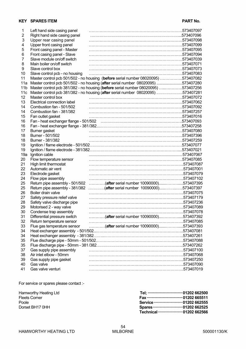
HAMWORTHY HEATING LTD
54 MILBORNE
500001130/K
KEY SPARES ITEM PART No. 1 Left hand side casing panel …………………………………………………………….573407097 2 Right hand side casing panel …………………………………………………………...573407096 3 Upper rear casing panel …………………………………………………………….573407098 4 Upper front casing panel …………………………………………………………….573407099 5 Front casing panel - Master …………………………………………………………….573407095 6 Front casing panel - Slave …………………………………………………………….573407094 7 Slave module on/off switch …………………………………………………………….573407039 8 Main boiler on/off switch …………………………………………………………….573407071 9 Slave control box …………………………………………………………….573407073 10 Slave control pcb - no housing …………………………………………………………….573407083 11 Master control pcb 501/502 - no housing (before serial number 08020095) ……………..573407082 11a Master control pcb 501/502 - no housing (after serial number 08020095) .........................573407280 11b Master control pcb 381/382 - no housing (before serial number 08020095) …..………….573407256 11c Master control pcb 381/382 - no housing (after serial number 08020095) .……………….573407281 12 Master control box …………………………………………………………….573407072 13 Electrical connection label …………………………………………………………….573407062 14 Combustion fan - 501/502 …………………………………………………………….573407092 14 Combustion fan - 381/382 …………………………………………………………….573407257 15 Fan outlet gasket …………………………………………………………….573407016 16 Fan - heat exchanger flange - 501/502 …………………………………………………….573407093 16 Fan - heat exchanger flange - 381 /382....…………………………………………………….573407258 17 Burner gasket …………………………………………………………….573407080 18 Burner - 501/502 …………………………………………………………….573407396 18 Burner - 381/382 …………………………………………………………….573407259 19 Ignition / flame electrode - 501/502……………………………………………………………573407077 19 Ignition / flame electrode - 381/382…………………………………………………………....573407021 19a Ignition cable ........................................................................................... 573407067 20 Flow temperature sensor …………………………………………………………….573407085 21 High limit thermostat ……………………………………………………………..573407087 22 Automatic air vent ……………………………………………………………..573407001 23 Electrode gasket ……………………………………………………………..573407079 24 Flow pipe assembly ……………………………………………………………..573407102 25 Return pipe assembly - 501/502 …………(after serial number 10090000).......……….....573407395 25 Return pipe assembly - 381/382 …………(after serial number 10090000)......……...…..573407397 26 Boiler drain valve ……………………………………………………………..573407075 27 Safety pressure relief valve ……………………………………………………………..573407179 28 Safety valve discharge pipe ……………………………………………………………..573407236 29 Motorised 2 - way valve ……………………………………………………………..573407089 30 Condense trap assembly ……………………………………………………………..573407078 31 Differential pressure switch …………(after serial number 10090000)...………….....573407392 32 Return temperature sensor ……………………………………………………………..573407085 33 Flue gas temperature sensor …………(after serial number 10090000).......……….....573407393 34 Heat exchanger assembly - 501/502...………………………………………………………..573407081 34 Heat exchanger assembly - 381/382……...…………………………………………………..573407261 35 Flue discharge pipe - 50mm - 501/502.………………………………………………………..573407088 35 Flue discharge pipe - 50mm - 381 /382………………………………………………………..573407262 37 Gas supply pipe assembly ……………………………………………………………..573407100 38 Air inlet elbow - 50mm ……………………………………………………………..573407068 39 Gas supply pipe gasket ……………………………………………………………..573407250 40 Gas valve ……………………………………………………………..573407090 41 Gas valve venturi ……………………………………………………………..573407019 For service or spares please contact :- Hamworthy Heating Ltd Tel; ·································· 01202 662500 Fleets Corner Fax ··································· 01202 665511 Poole Service ···························· 01202 662555 Dorset BH17 0HH Spares ····························· 01202 662525 Technical ························ 01202 662566

HAMWORTHY HEATING LTD
55 MILBORNE
500001130/K
APPENDIX A - GAS DATA
Natural Gas - A1
GAS DATA 381 382 501 502 Gas Inlet Connection Pipe Thread Size 1 - G3/4” 2 - G 3/4” 1 - G3/4” 2 - G 3/4” Nominal Gas Inlet Pressure - mbar 20 Maximum Gas Inlet Pressure - mbar 25 Gas Flow Rate (maximum) - m3/h 3.55 7.1 4.74 9.48 Target CO2 % at Low fire ±0.2% 8.3 - 8.5 Target CO2 % at High fire ±0.2% 9.2 - 9.4
GENERAL DATA Milborne - condensing BOILER MODEL
Model - Condensing 381 382 501 502 Boiler Input (maximum) - kW (Gross) 37.5 75 50 100 Boiler Input (maximum) - kW (Nett) 33.8 67.5 45 90 Boiler Output kW (maximum) condensing 50/30°C - kW 36.5 73 48.5 96.8 Boiler Output kW (maximum) non condensing 80/60°C - kW 32.5 65 44.2 88.3 Boiler Module Output (minimum) - kW 11 15
LPG Propane - A2
A2.1 Conversion to LPG Propane Note: It is strongly recommended that, on LPG installations, gas detection equipment is fitted. This equipment should be positioned near the boiler and at low level. It is important that the space housing the boiler is adequately ventilated at high and low level - refer to Appendix D. For single module installations, ie 1 x Milborne 381 / 501, the boiler must not be installed in a room or compartment located below ground level. BS6798. For multiple module installations, ie 1 x Milborne 382 / 502 or greater, the boiler must not be installed in a plant room located below ground level. BS6644.
GENERAL DATA Milborne - condensing BOILER MODEL
Model - Condensing 381 382 501 502 Boiler Input (maximum) - kW (Gross) 37.5 75 50 100 Boiler Input (maximum) - kW (Nett) 34.6 69.1 45 90 Boiler Output kW (maximum) condensing 50/30°C - kW 36.4 72.6 48.5 96.8 Boiler Output kW (maximum) non condensing 80/60°C - kW 33.2 66.4 44.2 88.3 Boiler Module Output (minimum) - kW 11 15
GAS DATA 381 382 501 502 Nominal Gas Inlet Pressure - mbar 37.5 Maximum Gas Inlet Pressure - mbar 50
Gas Flow Rate (maximum) - m3/h 1.4 2.8 1.9 3.8 Target CO2 % at Low fire ±0.2% 8.6 - 8.9 Target CO2 % at High fire ±0.2% 10.2 - 10.4
LPG orifice diameter - mm 6.50

HAMWORTHY HEATING LTD
56 MILBORNE
500001130/K
A2.2 Installation The design and operation of the Milborne boiler using LPG-propane (3rd family) I3P is similar to that on Natural Gas (2nd family) I2H and the design and installation details in the main body of this guide should be followed. There are however differences in the construction and commissioning requirements of the propane boiler as follows. The propane boiler is supplied with a gas orifice sized 6.50mm dia. fitted to the gas valve/venturi assembly before leaving the factory. Full commissioning details are provided in the operation and commissioning manual. LPG kits can also be supplied separately if required to convert the boilers from Natural Gas to LPG on site. To order additional LPG conversion kits please contact Hamworthy Heating Ltd to order the required number of kits quoting part number 573407132. One kit will be required for each module, ie; Milborne 381 / 501 1 kits. Milborne 382 / 502 2 kits. During commissioning the parameters must be set for propane firing to ensure correct fan speeds for ignition and operation are maintained. Hamworthy Heating Ltd strongly recommend that the Milborne boiler is commissioned by our engineers. This will ensure that the boiler is operating correctly and efficiently. LPG Conversion Kit (HHL Part No. 573407132) The LPG kit is supplied with 2 sizes of orifice. The 6.50mm orifice is used for the majority of installations. However, the 6.75mm orifice is occasionally used in special circumstances, see Section A2.3 point 7. A2.3 Procedure for Converting boiler from Natural Gas to LPG. 1 Ensure that the boiler is isolated from both the electrical supply and the gas supply. Remove the front cover to gain access to the internal boiler assemblies. 2 Figure A3 shows the gas valve and air inlet assemblies of the boiler. Where the boiler has two (2) modules then both modules will need to be modified for LPG gas supply. 3 The following operations can be performed on the installed boiler. For clarity purposes the illustrations show the assemblies removed from the boiler. 4 To separate the venturi from the gas valve remove the 3 screws as indicated in figure A4. When the parts are separated access to the gas valve air inlet passage is possible.
Figure A3
Figure A4
5. Following separation of the venturi from the gas valve the rubber seal will be clearly visible, see fig A5. All Milborne’s are supplied Natural Gas as standard so there will be no orifice fitted to the gas valve air inlet passage.
Figure A5
3 off securing screws
Gas Valve
LPG Orifice Location

HAMWORTHY HEATING LTD
57 MILBORNE
500001130/K
6. The LPG orifice consists of a precisely drilled washer of 6.5mm internal diameter. This orifice is to be fitted in the gas valve outlet port. There is no need to remove the rubber seal to complete this operation. 7. Figure A6 shows LPG gas orifice correctly located in the gas valve air inlet passage.
Figure A6
NOTE: In certain circumstances it is necessary to fit a larger LPG orifice to the gas valve air inlet port. If poor ignition is experienced after commissioning the boiler then the larger orifice may be fitted. It is important to commission the boiler first, as correctly setting the gas valve offset for clean combustion may overcome initial poor ignition. The alternative LPG orifice is sized at 6.75mm internal diameter and is fitted in exactly the same way as the 6.5mm diameter orifice. If fitting the larger orifice then the 6.5mm diameter orifice must first be removed.
Figure A7
8. To replace the assembly, ensure that all the components that have been removed and modified are clean. Position the venturi to the gas valve and refit 3 screws that were previously removed in step 4. Ensure the 3 screws are securely tightened to prevent leaks at the venturi to gas valve joint. 9. Modifying the Boiler Parameter, Master Boiler Only It is essential to modify the boiler parameter number 36 to identfy the type of gas being used. This must also take account of the flue length as indicated in the table below. To modify the parameter it is necessary to reinstate the gas and electrical supplies. WARNING! As the boiler MUST NOT fire before the parameter is modified ensure that there is no demand for heat from any of the connected circuits and time clock controls. Notes: 1. The procedure for modification and adjustment of the parameters at the Master Control Panel is detailed in Section 8.5 of this manual. 2. Once the boiler has been modified for LPG firing it is essential to complete the full commissioning procedure to all boiler modules as detailed in Section 7.0 3. If after commissioning, the larger orifice has to be installed then the full commissioning procedure as detailed in Section 7.0 must again be completed.
Parameter Description Range Default Specification
36
Type of Gas
1-24
1
501/502 boilers 1= Natural Gas with equivalent flue length < 15m 2= Natural Gas with equivalent flue length > 15m 3= LPG with equivalent flue length < 15m 4= LPG with equivalent flue length > 15m 381/382 boilers 21= Natural Gas with equivalent flue length < 15m 22= Natural Gas with equivalent flue length > 15m 23= LPG with equivalent flue length < 15m 24= LPG with equivalent flue length > 15m
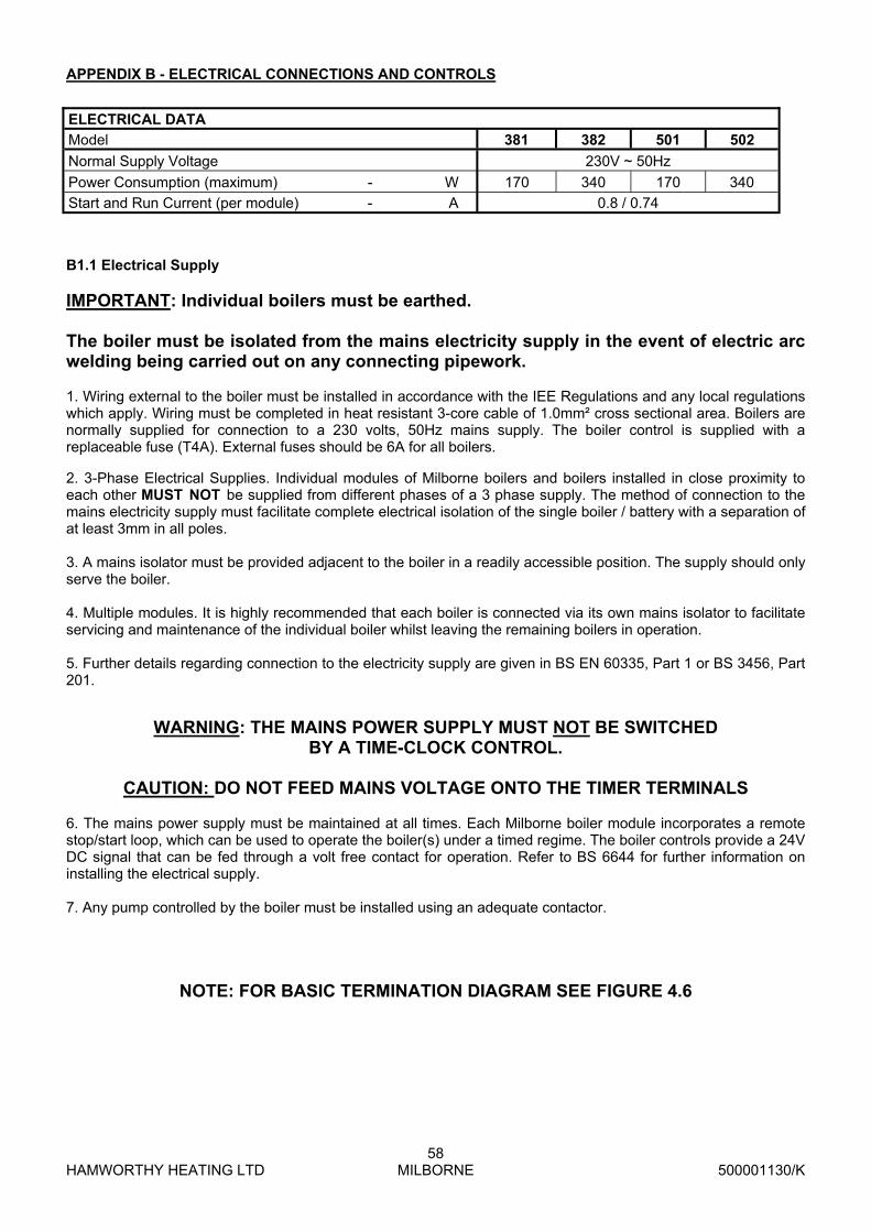
HAMWORTHY HEATING LTD
58 MILBORNE
500001130/K
APPENDIX B - ELECTRICAL CONNECTIONS AND CONTROLS
ELECTRICAL DATA Model 381 382 Normal Supply Voltage 230V ~ 50Hz Power Consumption (maximum) - W 170 340 Start and Run Current (per module) - A 0.8 / 0.74
501 502
170 340
B1.1 Electrical Supply IMPORTANT: Individual boilers must be earthed. The boiler must be isolated from the mains electricity supply in the event of electric arc welding being carried out on any connecting pipework. 1. Wiring external to the boiler must be installed in accordance with the IEE Regulations and any local regulations which apply. Wiring must be completed in heat resistant 3-core cable of 1.0mm² cross sectional area. Boilers are normally supplied for connection to a 230 volts, 50Hz mains supply. The boiler control is supplied with a replaceable fuse (T4A). External fuses should be 6A for all boilers. 2. 3-Phase Electrical Supplies. Individual modules of Milborne boilers and boilers installed in close proximity to each other MUST NOT be supplied from different phases of a 3 phase supply. The method of connection to the mains electricity supply must facilitate complete electrical isolation of the single boiler / battery with a separation of at least 3mm in all poles. 3. A mains isolator must be provided adjacent to the boiler in a readily accessible position. The supply should only serve the boiler. 4. Multiple modules. It is highly recommended that each boiler is connected via its own mains isolator to facilitate servicing and maintenance of the individual boiler whilst leaving the remaining boilers in operation. 5. Further details regarding connection to the electricity supply are given in BS EN 60335, Part 1 or BS 3456, Part 201.
WARNING: THE MAINS POWER SUPPLY MUST NOT BE SWITCHED BY A TIME-CLOCK CONTROL.
CAUTION: DO NOT FEED MAINS VOLTAGE ONTO THE TIMER TERMINALS
6. The mains power supply must be maintained at all times. Each Milborne boiler module incorporates a remote stop/start loop, which can be used to operate the boiler(s) under a timed regime. The boiler controls provide a 24V DC signal that can be fed through a volt free contact for operation. Refer to BS 6644 for further information on installing the electrical supply. 7. Any pump controlled by the boiler must be installed using an adequate contactor.
NOTE: FOR BASIC TERMINATION DIAGRAM SEE FIGURE 4.6

HAMWORTHY HEATING LTD
59 MILBORNE
500001130/K
Pump Connection Milborne boiler regulation system includes the simultaneous management of up to three circulators. Therefore, if a low temperature circuit supplied by its own circulator is present and a general pump is to be installed on the system, it will be necessary to choose which one of the two devices should be managed by the Boiler Master Control. This operation is carried out by setting the relevant parameter during commissioning. The pumps shall be installed using an adequate contactor, as shown in Figure B.1.2
Figure B.1.2
BMS Connections For 0 - 10v connection, the input signal must be connected to terminals 13 & 14 - see figure B.1.3 Note: any safety interlocks MUST be wired across the 0– 10v circuit using suitable low voltage contact ratings. For connection of an external alarm device, use terminals 18 & 19, which are volt free and rated at 230v - see figure B.1.3 For an optional programmable room thermostat, use terminals 9 & 10 for the high temperature heating room sensor and terminals 11 & 12 for the low temperature heating room sensor - see figure B.1.3
Figure B.1.3

HAMWORTHY HEATING LTD
60 MILBORNE
500001130/K
APPENDIX C - FLUE DATA - Natural Gas & LPG
FLUE DATA Model - Condensing 381 382 Approx. Flue Gas Temperature @ 80/60°C - °C (Gross) 65
Pressure at the boiler flue outlet - Pa/mbar 700 / 7.0 Approx. Flue Gas Volume @ 9% CO2 - m3/h* 56 113
Approx. Flue Gas Temperature @ 50/30°C - °C (Gross) 35
501 502
75 150
C1.0 FLUE SYSTEM 1. Detailed recommendations for flue systems are given in BS 6644, and IGE/UP/10. All flue discharges for plant exceeding 150kW output must comply with the third edition of the 1956 Clean Air Act Memorandum.
WARNING: THE FLUE DISCHARGE FROM A MILBORNE BOILER WILL GENERATE A PLUME AT THE TERMINAL EXIT. THIS MUST BE CONSIDERED WITH REGARD TO
TERMINAL LOCATION AND ADJACENT BUILDING FABRIC. C1.1 General Requirements The Hamworthy Milborne boilers are designed to be used with natural draught or room sealed flues. Flue systems should be designed in accordance with regulations and with reference to BS 6644 and IGE/UP/10. The following points should be noted: a. Due to the high thermal efficiency of the boiler, condensation will occur in the flue. It is strongly recommended that the design of the flue system recognises this. b. Care should be taken to ensure that the flue is installed such that any condensation is continuously drained. Any flue system with a horizontal section should have a maximum slope of 2° upwards in the direction of the exhaust gas flow. All joints should be such that any condensation is directed back down the slope to an open drain connection in the flue. The drain pipe must be manufactured from a corrosion resistant material and be at least 15mm diameter. It must also have a fall of at least 2-3° (approx. 30-50mm per meter) and connect to a drain via a waste trap. c. Boiler flue outlet sizes - A flue system designed with the same diameter as the boiler flue outlet may not provide satisfactory performance in all applications. Consideration must be given to the correct calculation of the required flue size. If in any doubt consult Hamworthy Heating Ltd who can supply a full flue design and installation service. C1.2 Waste Gas Volume and Temperature. It is recommended that the volume and temperature of the waste gases used for design of the flue system are as given in the above tables. C1.3 Materials. Materials used for the flue system must be mechanically robust, resistant to internal and external corrosion, non-combustible and durable under the conditions to which they are likely to be subjected. Consideration must be given to avoid possible freezing of condense water traps and pipework. C1.4 Suction The flue system should be designed to maintain atmospheric pressure or a slight suction at the boiler flue connection at all times acknowledging the positive pressure available from the combustion fan. C1.5 Disconnection Provisions should be made for disconnection of the flue pipe for servicing. It is advisable that bends are fitted with removable covers for inspection and cleaning as appropriate.
* Note:- Flue gas volumes are corrected to a flue gas temperature of 15°C and barometric pressure of 1013.25mbar.

HAMWORTHY HEATING LTD
61 MILBORNE
500001130/K
WARNING: THE FLUE SYSTEM MUST BE SELF SUPPORTING AND NOT PRESENT A RISK TO PEOPLE IN OR AROUND THE BUILDING.
C1.6 Flue Discharge The flue system must ensure safe and efficient operation of the boiler to which it is attached, protect the combustion process from wind effects and disperse the products of combustion to the external air. The flue must terminate in a freely exposed position and be so situated as to prevent the products of combustion entering any opening in a building. Where the flue diameter is less than 204mm (8”) diameter a terminal must be fitted. Where the flue is of a larger size, consideration should be given to the fitting of a flue discharge terminal or grille to stop ingress of birds etc. C1.7 Surface Temperatures Combustible materials in the vicinity of the boiler and flue shall not exceed 65°C during boiler operation. The flue shall not be closer than 50mm to any combustible material, except where it passes through such material with a non-combustible sleeve when the air gap may not be less than 25mm. C1.8 Location The flue system must not be placed or fitted where there is undue risk of accidental damage to the flue pipe or undue danger to persons in the vicinity. Check that the flue and chimney are clear from any obstruction. Milborne boilers are suitable for installation in a balanced compartment in accordance with the requirements of BS 6644. Consult Hamworthy Heating Technical Department for help or assistance if in doubt. C1.9. Condensate Discharge Due to the high thermal efficiency of the boiler, condensation will occur within the boiler casing during firing from cold conditions. A drain with an integral trap is fitted to each module suitable for connection to a 20mm plastic waste pipe (not Hamworthy Heating Ltd supply), which must be connected to a tundish (not Hamworthy Heating Ltd supply). Discharge piping from a tundish should be of synthetic material due to the mild acidity of the condensate (pH3-5), with all discharge piping having a minimum fall of 30mm/m away from the boiler. Consideration should be given to possible freezing of condense water traps and pipework. This must be avoided at all times by routing pipework within the building, where possible. In addition to the above, should the plastic flue system supplied discharge into a metallic chimney system, any condensate formed in the chimney MUST NOT drain back through the plastic components to the boiler. A separate drain for the chimney system must be provided.
Module kW
Equivalent lengths (m) Flue pressure
(Pa) Max length
45° Bend 90° Bend
38 40 1.0 3.0 410
50 31 1.0 3.0 560
125mm 1.3 5.3
160mm 1.7 7.6
Note: flue pressure quoted at full output
Figure C1.1 - 50mm Flue equivalent lengths
No. Of Modules
Nominal cascade output
kW 125mm 160mm
2*38 76 428 n/a
3*38 112 176 n/a
4*38 150 103 n/a
5*38 187 65 n/a
6*38 225 45 n/a
2*50 100 300 n/a
3*50 150 134 n/a
4*50 200 75 n/a
5*50 250 47 150
6*50 300 33 105
7*50 350 n/a 78
8*50 400 n/a 60
Maximum length (m) of open flue system
B23 incl. header
9*50 450 n/a 46
10*50 500 n/a 38
Figure C1.2 - 125/160mm Maximum flue lengths

HAMWORTHY HEATING LTD
62 MILBORNE
500001130/K
APPENDIX D - VENTILATION D1.1 Air Supply Detailed recommendations for air supply are given in BS 6644 and BS5440 Pt 2. The following notes are intended to give general guidance. In all cases there must be provision for an adequate supply of air for both combustion and general ventilation, in addition to that required for any other appliance. Note: For Open flue applications, combustion air for the boiler is drawn through the top of the boiler casing. The air inlets must be kept open and free from blockage at all times. D1.2.1 Air Supply by Natural Ventilation - Open Flue applications The boiler room must have, or be provided with, permanent air vents directly to the outside air, at high level and at low level. For an exposed boiler house, air vents should be fitted, preferably on all four sides, but at the least on two sides. Air vents should have negligible resistance and must not be sited in any position where they are likely to be easily blocked or flooded or in any position adjacent to an extraction system which is carrying flammable vapour. Grilles or louvres must be so designed that high velocity air streams do not occur within the space housing the boiler.
Boiler house ventilation
Low level (inlet) - 4cm² per kW of total rated input (Net) High level (output) - 2cm² per kW of total rated input (Net)
Compartment ventilation Where the boiler is to be installed in a cupboard or compartment, permanent high and low level ventilation is required which must communicate direct to outside, for cooling purposes.
Low level (inlet) - 10cm² per kW of total rated input (Net) High level (output) - 5cm² per kW of total rated input (Net)
D1.2.2 Air Supply by Natural Ventilation - Room Sealed Installations Where the boiler(s) are to be installed in a boiler room or internal space, the room or internal space must have permanent air vents directly to the outside air, at high level and at low level with the general requirements detailed above on location and construction. Boiler house ventilation
Low level (inlet) - 2cm² per kW of total rated input (Net) High level (output) - 2cm² per kW of total rated input (Net)
Compartment ventilation Where the boiler is to be installed in a cupboard or compartment, permanent high and low level ventilation is required which may communicate to an adjoining room or outside, for cooling purposes.
Ventilation to a room or internal space - 10cm² per kW of total rated input (Net) Ventilation direct to outside - 5cm² per kW of total rated input (Net)
D1.3 Air Supply by Mechanical Ventilation Air supplied to the boiler room by Mechanical means should be as follows:
1) Mechanical ventilation must be interlocked with the boilers to prevent operation in the event of ventilation fan failure 2) Mechanical inlet and mechanical extract can be utilised providing the design extraction rate does not exceed one third of the design inlet rate. 3) Mechanical extract ventilation with natural inlet ventilation MUST NOT be used.
For Mechanical ventilation systems an automatic control should be provided to cut off the gas supply to the boiler, in the event of failure of air flow in either inlet or extract fans.

HAMWORTHY HEATING LTD
63 MILBORNE
500001130/K
Figure D1 Mechanical Ventilation Flow Rates
Flow rate per kW total rated heat input (Net) Inlet air
(Combustion ventilation)
Difference between Inlet & Extract air *
m³/h. m³/h. Volume 2.6 1.35
Note * : Where the associated air extraction is also by means of a fan, this shall be selected such as not to cause a negative pressure to develop in the boiler house and to maintain the difference between inlet and extract flow rates shown above. The calculated extract flow rate is the actual inlet flow rate minus the appropriate figure in the table above.
D 1.4. Boiler House Temperatures
The air supplied for boiler house ventilation shall be such that the maximum temperatures within the boiler house shall be as follows:
At floor level (or 100mm above floor level) = 25°C.
At mid-level (1.5m above floor level) = 32°C.
At ceiling level (or 100mm below ceiling level) = 40°C.
D 1.5. General Requirements
The air supply should be free from contamination such as building dust and insulation fibres from lagging. To avoid unnecessary cleaning and servicing of the boiler modules, the boilers should not be fired whilst building work is being undertaken. High and low level ventilation grilles shall be positioned as high and as low as practicably possible. Low level grilles should be located within 1 metre of the floor for Natural Gas and within 250mm of the floor for LPG. High level grilles should be positioned within 15% of the boiler room height from the ceiling. High and low level grilles shall communicate with the same room or space where compartment ventilation is used. Where grilles communicate directly with outside air, they shall be positioned on the same wall.

HAMWORTHY HEATING LTD
64 MILBORNE
500001130/K
APPENDIX E - WATER DATA WATER DATA
Model 381 382 501 502 Water Connections (Flow & Return) G 1” male
Maximum Water Pressure - bar g 6
Minimum Water Pressure - bar g 0.5 Water Content (not including headers) - litres 3.5 4.9 7.0 9.8 Design Flow Rate @ 20°C ΔT Rise - litre/s 0.42 0.55 0.84 1.1 Waterside Pressure Loss @ 20°C ΔT Rise - mbar 300 700
E1.1 Water Circulation System The Milborne boiler has a low water content and the requirements of minimum water flow are given in the above table. Recommendations for the water circulation system are given in BS 6644 and CP 342. The following details are of particular importance for the correct installation of the water circulation system:
1) In a combined central heating and hot water system the hot water storage vessel must be of the indirect cylinder or calorifier type. The hot water storage vessel should be insulated, preferably with not less than 75mm (3”) thick mineral fibre, or its thermal equivalent.
2) Circulating pipework not forming part of the useful heating surface should be insulated to help prevent heat loss and possible freezing, particularly where pipes are run through roof spaces and ventilated cavities. Cisterns situated in areas which may be exposed to freezing conditions should also be insulated. Furthermore, insulation exposed to the weather should be rendered waterproof.
3) Drain valves must be located in accessible positions which permit the draining of the whole system, including the boiler and hot water storage vessel.
4) Each boiler module has G1” male flow and return connections. Boilers should be connected by flow and return headers. Hamworthy strongly recommend that boilers are connected in a primary circuit configuration utilising a low loss header arrangement to enable secondary circuits to be connected to the header. Figure E1.1.1 on the following page show typical layouts.
5) Ideally, individual valves should be fitted to each module to enable isolation from the system, however, the arrangement must comply with the requirements of BS 6644.
E1.2 Pressure Relief Valve (Safety Valve) The most important single safety device fitted to a boiler is its safety valve. Each boiler module is provided with an integral safety valve terminating in a 22mm stub pipe on the base of the boiler. BS 6644 provides comprehensive information for the selection and location of safety valves and attention is drawn to the higher capacity requirements of safety valves for pressurised hot water systems. E1.3 Altitude Gauge (Water Pressure Gauge) Every boiler or group of boilers should be provided with an altitude gauge complete with isolating valve. See Figure E1.1.1 for typical position. E1.4 Thermometer A thermometer complete with pocket should be fitted in the pipework to indicate water flow temperature. See Figure E1.1.1 for typical position. E1.5 Drain Valves Each boiler should have a 15mm NB drain valve (not Hamworthy Heating Ltd supply) fitted in the boiler return to drain the boiler only. The heating system in total should have drain valves as recommended by BS 6644. See Figure E1.1.1 for typical position. E1.6 Circulating Pump It is recommended by Hamworthy Heating, that the primary pump MUST be controlled from the Master boiler to ensure synchronised operation - refer to fig. 4.6.

HAMWORTHY HEATING LTD
65 MILBORNE
500001130/K
One or more circulating pumps will be required to circulate water around the boilers and heating system. The pump should be sited to facilitate servicing. It is important that when Milborne boilers are used to replace boilers on an existing system, the pumps should be checked for performance against the new boiler waterside pressure loss to ensure that the minimum flow rate can be obtained. It is also important that the existing system be flushed through twice to remove any loose matter which may have accumulated. If in any doubt regarding the cleanliness of the system, a coarse filter should be fitted in the return pipework to the boilers E1.7 Minimum Water Flow Rates Minimum water flow rates are shown in table at beginning of Appendix E. These flow rates should be maintained through the boiler at all times whilst the boiler is firing. If the water flow rate is allowed to fall below the minimum the boiler heat exchanger could fail due to the resultant scale formation. Particular attention should be paid to the restriction of external flow circuits during periods of low heat demand. E1.8 Waterside Pressure Drop The waterside hydraulic resistance (Pressure drop) is given in table at beginning of Appendix E. E1.9 Water Flow Controls The Milborne boiler is fitted with an electrical isolating valve, which will shut off circulation through the heat exchanger 5 minutes after the boiler has ceased firing. Any external mixing valve / shunt pump or similar controls MUST always ensure that the minimum water flow rate as given in table at beginning of Appendix E is maintained. As a precaution, the Milborne boiler is fitted with a flow switch. The flow switch is designed to operate such that the boiler will shut down if insufficient flow occurs. E1.10 Frost Protection Consideration should be given to fitting an optional outside air sensor, to provide the necessary frost protection. E1.11 Unvented Systems Refer to Figure E1.1.1 on opposite page for typical layout of an unvented (Pressurised) Hot Water System. For system design refer to BS 7074 Part 2. In order to correctly size a pressurisation unit for any heating system the following parameters are required.
1) Static height of highest component in system (metres) 2) System volume. If this is not known, a general rule of thumb of 10litres/kW of installed boiler power
can be used. 3) Maximum flow temperature (°C) 4) Maximum system hot working pressure, generally given in bar gauge.
From the parameters given, Hamworthy Heating can size the pressurisation unit and also the expansion vessel. Care must be taken in sizing expansion vessels to ensure maximum acceptance factors are not exceeded. Normally manufacturers of vessels impose a limit of 0.5. This value must not be exceeded at any time during the operation of the boiler, this includes the over pressure condition should a safety valve lift. Consideration should also be given to sizing of the safety valve(s) in the system. Refer to BS 6759: Part 1 for further information and to BS 6880: Part 1 for design considerations.
No. of Boilers System Load kW
Pump Model
1 100 Biral HX501-1
2 150 Biral HX501-1
2 200 Biral HX501-1
3 250 Biral HX501-1
3 300 Biral HX501-1
4 350 Biral HX502-1
4 400 Biral HX502-1
Pump Model
Biral LX403
Biral LX403
Biral LX403
Biral LX503
Biral LX503
Biral LX504
Biral LX504
System Load kW
75
112.5
150
187.5
225
262.5
300
1 37.5 Biral MX13-1 50 Biral M15-1
Figure E1.6 - Pump selection

HAMWORTHY HEATING LTD
66 MILBORNE
500001130/K
Figure E1.1.1 - Typical Piping Layouts
UNVENTED SYSTEM: Primary loop, Hamworthy recommended system.
Valve
Air VentAutomatic
Valve
valveDrain
Valve
Module
Hamworthy Modular Boilers
Safety
T
va lve
Module1 2
Drain
3Module
P gauges
Pressure &Temperature
T AutomaticAir Vent
He ating load
Locks hieldvalve f ill line
Temporary Do ublecheckvalve
vesselEx pansion
valveLoc kshie ld
Ma ins water
valveDrain
valveLockshield
(System)Circulation pump
(Primary loo p)Circulation pump
Circ ulatio n pum p
Hamworthy Modular Boilers
Mo dule
Drain
UNVENTED SYSTEM: Single pipe header
1
Circulation pump
Module2
Module3
Temperaturegauges
Pressure &
Safetyvalve
P T
He ating load
AutomaticAir Vent
Valve
(System)
Valv e
(Primary loop)Locks hield
valve
Ma ins water
Loc kshie ldvalve
Drainvalve
vessel
Temporaryf ill line
valveLockshield
Do uble
valvecheck
Ex pansion
Air VentAutomatic
Valve
valveDrain

HAMWORTHY HEATING LTD
67 MILBORNE
500001130/K
NOTES:

HAMWORTHY HEATING LTD
68 MILBORNE
500001130/K
INSTALLER SITE ADDRESS
BOILER TYPE BOILER SIZE(S) UNIT NO(S). SERIAL NO(S). FLUE
USEFUL USER INFORMATION


Hamworthy Heating Accredited Agents
Customer Service Centre Hamworthy Heating Limited, Fleets Corner, Poole, Dorset BH17 0HH Telephone: 0845 450 2866 Fax: 01202 662522 Email: [email protected] Website: www.hamworthy-heating.com Hamworthy reserves the right to make changes and improvements which may necessitate alteration to the specification without prior notice.
North West England
Gillies Modular Services 210-218 New Chester Road, Birkenhead, Merseyside L41 9BG tel: 0151 666 1030 fax: 0151 647 8101 Southern Ireland
HEVAC Limited Naas Road, Dublin 12, Ireland tel: 00 353 141 91919 fax: 00 353 145 84806 Northern Ireland
HVAC Supplies Limited Unit 12 forty 8 north, 48 Duncrue Street, Belfast BT3 9BJ tel: 02890 747737 fax: 02890 741233
Scotland
McDowall Modular Services 14-46 Lomond Street, Glasgow, Scotland G22 6JD tel: 0141 336 8795 fax: 0141 336 8954 North East England
Allison Heating Products 12 Sunnyside Lane, Cleadon Village, Sunderland SR6 7XB tel: 0191 536 8833 fax: 0191 536 9933