Embed Size (px)
Citation preview

2210 Second Avenue
Muscatine, IA 52761-5257
70-0010
06/07/11
MODEL: CAPE
IMPORTANT
CONCENSYS®
INSTALLATION
INSTRUCTIONS INSIDE
ENGLISH VERSION
POUR DES INSTRUCTIONS EN FRANCAIS,
APPELER LE 800-822-7653
PARA INSTRUCCIONES EN ESPANOL,
LLAME AL 800-822-7653
6 31530 52006 7

IMPORTANT
Do not connect 32" tall panels to a panel, or
panel/stacker assembly, 72" tall or taller.
IN
STA
LL
AT
IO
N I
NS
TR
UC
TIO
NS
43-0150I
(1/04)
SYSTEMS GUIDELINES - PANELSConcensys®
Read all instructions and review illustrations
before installing.
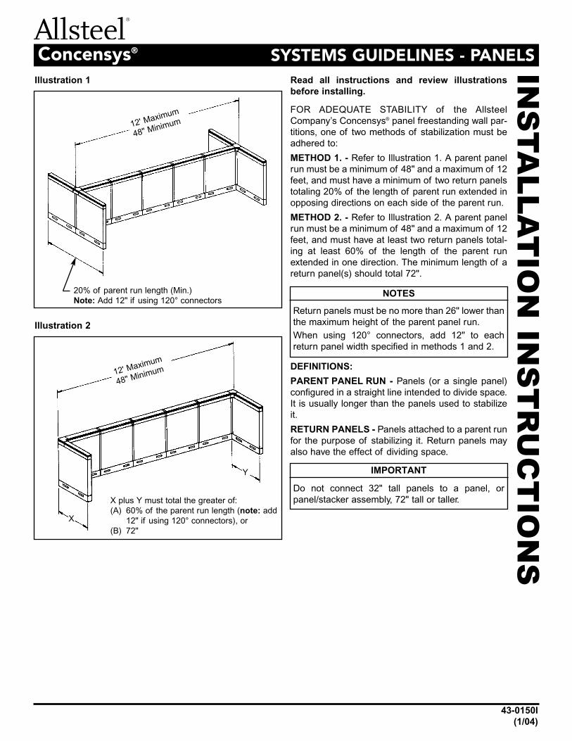
Illustration 1
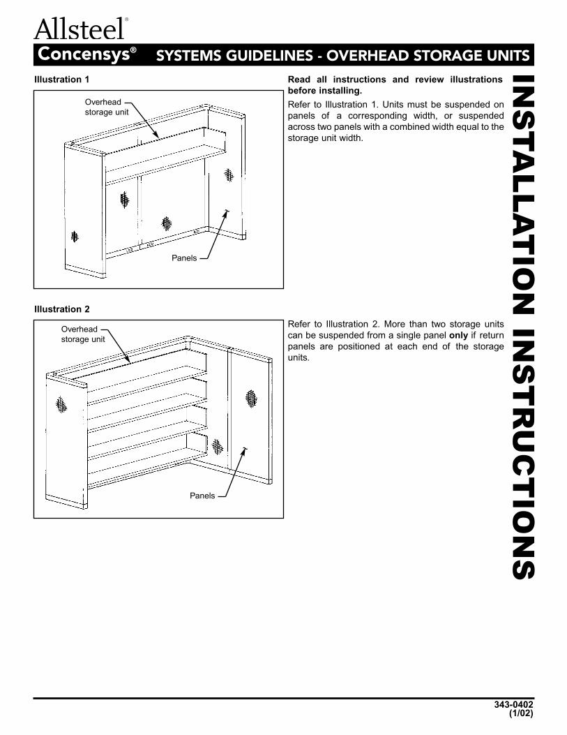
Illustration 2
FOR ADEQUATE STABILITY of the Allsteel
Company’s Concensys® panel freestanding wall par-
titions, one of two methods of stabilization must be
adhered to:
METHOD 1. - Refer to Illustration 1. A parent panel
run must be a minimum of 48" and a maximum of 12
feet, and must have a minimum of two return panels
totaling 20% of the length of parent run extended in
opposing directions on each side of the parent run.
METHOD 2. - Refer to Illustration 2. A parent panel
run must be a minimum of 48" and a maximum of 12
feet, and must have at least two return panels total-
ing at least 60% of the length of the parent run
extended in one direction. The minimum length of a
return panel(s) should total 72".
DEFINITIONS:
PARENT PANEL RUN - Panels (or a single panel)
configured in a straight line intended to divide space.
It is usually longer than the panels used to stabilize
it.
RETURN PANELS - Panels attached to a parent run
for the purpose of stabilizing it. Return panels may
also have the effect of dividing space.
12' Maximum
48" Minimum
12' Maximum
48" Minimum
X plus Y must total the greater of:
(A) 60% of the parent run length (note: add
12" if using 120° connectors), or
(B) 72"
X
Y
NOTES
Return panels must be no more than 26" lower than
the maximum height of the parent panel run.
When using 120° connectors, add 12" to each
return panel width specified in methods 1 and 2.
20% of parent run length (Min.)
Note: Add 12" if using 120° connectors
IN
STA
LL
AT
IO
N I
NS
TR
UC
TIO
NS
343-0402(1/02)
SYSTEMS GUIDELINES - OVERHEAD STORAGE UNITSConcensys®
Read all instructions and review illustrations
before installing.
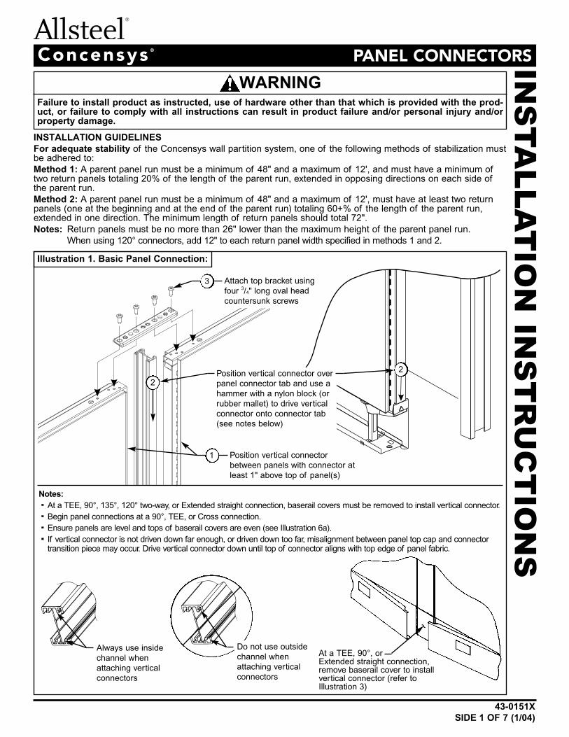
Illustration 1
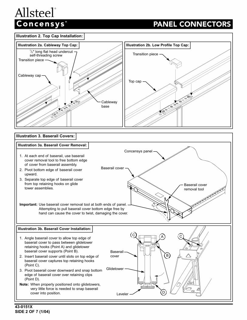
Illustration 2
Panels
Overhead
storage unit
~
Panels
Overhead
storage unit
~
Refer to Illustration 1. Units must be suspended on
panels of a corresponding width, or suspended
across two panels with a combined width equal to the
storage unit width.
Refer to Illustration 2. More than two storage units
can be suspended from a single panel only if return
panels are positioned at each end of the storage
units.
Failure to install product as instructed, use of hardware other than that which is provided with the prod-uct, or failure to comply with all instructions can result in product failure and/or personal injury and/orproperty damage.
IN
STA
LL
AT
IO
N I
NS
TR
UC
TIO
NS
Concensys ®
PANEL CONNECTORS
43-0151X
SIDE 1 OF 7 (1/04)
INSTALLATION GUIDELINES
For adequate stability of the Concensys wall partition system, one of the following methods of stabilization mustbe adhered to:
Method 1: A parent panel run must be a minimum of 48" and a maximum of 12', and must have a minimum oftwo return panels totaling 20% of the length of the parent run, extended in opposing directions on each side ofthe parent run.
Method 2: A parent panel run must be a minimum of 48" and a maximum of 12', must have at least two returnpanels (one at the beginning and at the end of the parent run) totaling 60+% of the length of the parent run,extended in one direction. The minimum length of return panels should total 72".
Notes: Return panels must be no more than 26" lower than the maximum height of the parent panel run.
When using 120° connectors, add 12" to each return panel width specified in methods 1 and 2.
WARNING
Illustration 1. Basic Panel Connection:
Always use inside
channel when
attaching vertical
connectors
At a TEE, 90°, or Extended straight connection,remove baserail cover to install vertical connector (refer toIllustration 3)
Notes:
· At a TEE, 90°, 135°, 120° two-way, or Extended straight connection, baserail covers must be removed to install vertical connector.
· Begin panel connections at a 90°, TEE, or Cross connection.
· Ensure panels are level and tops of baserail covers are even (see Illustration 6a).
· If vertical connector is not driven down far enough, or driven down too far, misalignment between panel top cap and connectortransition piece may occur. Drive vertical connector down until top of connector aligns with top edge of panel fabric.
Do not use outside
channel when
attaching vertical
connectors
~
Position vertical connector
between panels with connector at
least 1" above top of panel(s)
Attach top bracket using
four 3/4" long oval head
countersunk screws
Position vertical connector over
panel connector tab and use a
hammer with a nylon block (or
rubber mallet) to drive vertical
connector onto connector tab
(see notes below)
1
3
2
2
Concensys ®
PANEL CONNECTORS
43-0151X
SIDE 2 OF 7 (1/04)
Illustration 2. Top Cap Installation:
Illustration 3. Baserail Covers:
Illustration 2a. Cableway Top Cap:
Illustration 3a. Baserail Cover Removal:
Illustration 3b. Baserail Cover Installation:
Illustration 2b. Low Profile Top Cap:
1/2" long flat head undercutself-threading screw
Transition piece
Cableway cap
Transition piece
Top cap
Cableway
base
Concensys panel
Baserail cover
Baserail cover
removal tool
1. At each end of baserail, use baserail
cover removal tool to free bottom edge
of cover from baserail assembly.
2. Pivot bottom edge of baserail cover
upward.
3. Separate top edge of baserail cover
from top retaining hooks on glide
tower assemblies.
Important: Use baserail cover removal tool at both ends of panel.
Attempting to pull baserail cover bottom edge free by
hand can cause the cover to twist, damaging the cover.
1. Angle baserail cover to allow top edge of
baserail cover to pass between glidetower
retaining hooks (Point A) and glidetower
baserail cover supports (Point B).
2. Insert baserail cover until slots on top edge of
baserail cover captures top retaining hooks
(Point C).
3. Pivot baserail cover downward and snap bottom
edge of baserail cover over retaining clips
(Point D).
Note: When properly positioned onto glidetowers,
very little force is needed to snap baserail
cover into position.
AC C
B
D
Baserail
cover
Glidetower
Leveler
Concensys ®
PANEL CONNECTORS
43-0151X
SIDE 3 OF 7 (1/04)
Perform Steps 1 and8 as described above
Top cap
Bracket/
transition
piece
assembly
3/4" long oval head
countersunk screw
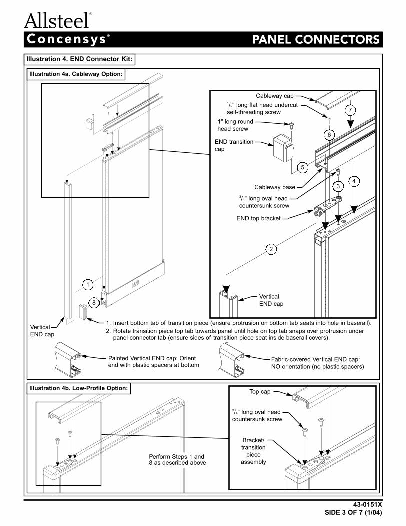
Illustration 4. END Connector Kit:
Cableway cap
1. Insert bottom tab of transition piece (ensure protrusion on bottom tab seats into hole in baserail).
2. Rotate transition piece top tab towards panel until hole on top tab snaps over protrusion underpanel connector tab (ensure sides of transition piece seat inside baserail covers).
Fabric-covered Vertical END cap:
NO orientation (no plastic spacers)
Cableway base
END transition
cap
Vertical
END cap
Vertical
END cap
END top bracket
3/4" long oval head
countersunk screw
1/2" long flat head undercut
self-threading screw 7
6
5
2
1
8
34
Illustration 4a. Cableway Option:
Illustration 4b. Low-Profile Option:
1" long round
head screw
Painted Vertical END cap: Orientend with plastic spacers at bottom
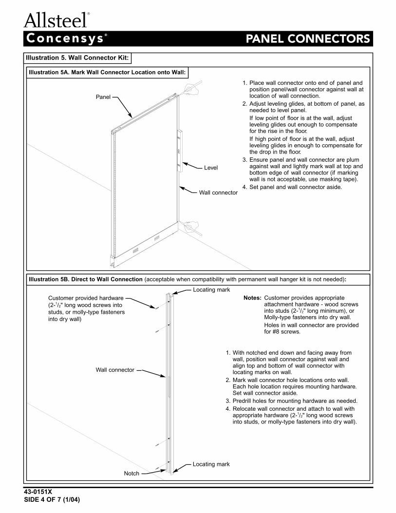
Illustration 5. Wall Connector Kit:
Illustration 5A. Mark Wall Connector Location onto Wall:
Illustration 5B. Direct to Wall Connection (acceptable when compatibility with permanent wall hanger kit is not needed):
Concensys ®
PANEL CONNECTORS
43-0151X
SIDE 4 OF 7 (1/04)
1. Place wall connector onto end of panel andposition panel/wall connector against wall atlocation of wall connection.
2. Adjust leveling glides, at bottom of panel, asneeded to level panel.
If low point of floor is at the wall, adjustleveling glides out enough to compensatefor the rise in the floor.
If high point of floor is at the wall, adjustleveling glides in enough to compensate forthe drop in the floor.
3. Ensure panel and wall connector are plumagainst wall and lightly mark wall at top andbottom edge of wall connector (if markingwall is not acceptable, use masking tape).
4. Set panel and wall connector aside.
1. With notched end down and facing away fromwall, position wall connector against wall andalign top and bottom of wall connector withlocating marks on wall.
2. Mark wall connector hole locations onto wall.Each hole location requires mounting hardware.Set wall connector aside.
3. Predrill holes for mounting hardware as needed.
4. Relocate wall connector and attach to wall withappropriate hardware (2-1/2" long wood screwsinto studs, or molly-type fasteners into dry wall).
Notes: Customer provides appropriateattachment hardware - wood screwsinto studs (2-1/2" long minimum), orMolly-type fasteners into dry wall.
Holes in wall connector are providedfor #8 screws.
Panel
Level
Wall connector
Wall connector
Locating mark
Locating mark
Notch
Customer provided hardware
(2-1/2" long wood screws into
studs, or molly-type fasteners
into dry wall)
Concensys ®
PANEL CONNECTORS
43-0151X
SIDE 5 OF 7 (1/04)
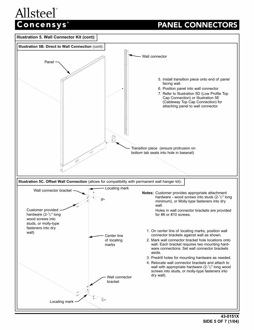
Illustration 5. Wall Connector Kit (cont):
Illustration 5B. Direct to Wall Connection (cont):
5. Install transition piece onto end of panelfacing wall.
6. Position panel into wall connector.
7. Refer to Illustration 5D (Low Profile TopCap Connection) or Illustration 5E(Cableway Top Cap Connection) forattaching panel to wall connector.
Notes: Customer provides appropriate attachmenthardware - wood screws into studs (2-1/2" longminimum), or Molly-type fasteners into drywall.
Holes in wall connector brackets are providedfor #8 or #10 screws.
Illustration 5C. Offset Wall Connection (allows for compatibility with permanent wall hanger kit):
Wall connector
Transition piece (ensure protrusion on
bottom tab seats into hole in baserail)
Panel
1. On center line of locating marks, position wallconnector brackets against wall as shown.
2. Mark wall connector bracket hole locations ontowall. Each bracket requires two mounting hard-ware connections. Set wall connector bracketsaside.
3. Predrill holes for mounting hardware as needed.
4. Relocate wall connector brackets and attach towall with appropriate hardware (2-1/2" long woodscrews into studs, or molly-type fasteners intodry wall).
Wall connector
bracket
Center line
of locating
marks
Wall connector bracket
6"
1/4"
Customer provided
hardware (2-1/2" long
wood screws into
studs, or molly-type
fasteners into dry
wall)
Locating mark
Locating mark
Concensys ®
PANEL CONNECTORS
43-0151X
SIDE 6 OF 7 (1/04)
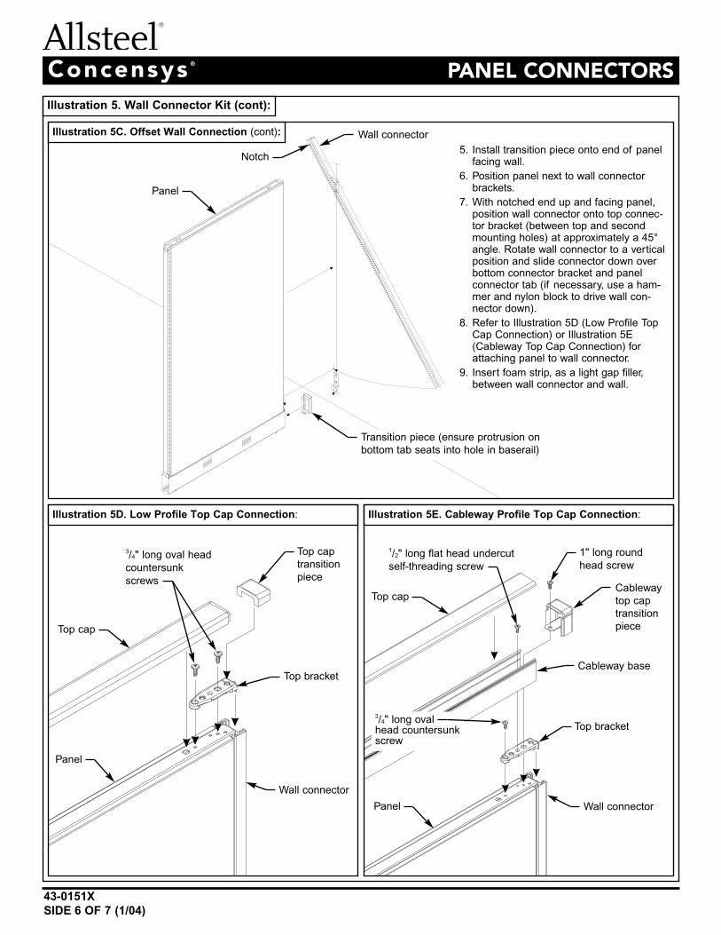
Illustration 5. Wall Connector Kit (cont):
Illustration 5C. Offset Wall Connection (cont):
5. Install transition piece onto end of panelfacing wall.
6. Position panel next to wall connectorbrackets.
7. With notched end up and facing panel,position wall connector onto top connec-tor bracket (between top and secondmounting holes) at approximately a 45°angle. Rotate wall connector to a verticalposition and slide connector down overbottom connector bracket and panelconnector tab (if necessary, use a ham-mer and nylon block to drive wall con-nector down).
8. Refer to Illustration 5D (Low Profile TopCap Connection) or Illustration 5E(Cableway Top Cap Connection) forattaching panel to wall connector.
9. Insert foam strip, as a light gap filler,between wall connector and wall.
Illustration 5D. Low Profile Top Cap Connection: Illustration 5E. Cableway Profile Top Cap Connection:
Top cap
3/4" long oval head
countersunk
screws
1" long round
head screw
1/2" long flat head undercut
self-threading screw
Wall connector
Wall connector
Top bracket
Top cap
transition
piece
Transition piece (ensure protrusion on
bottom tab seats into hole in baserail)
Panel
Panel
Top cap
3/4" long ovalhead countersunkscrew
Wall connector
Top bracket
Cableway
top cap
transition
piece
Cableway base
Panel
Notch
Concensys ®
PANEL CONNECTORS
43-0151X
SIDE 7 OF 7 (1/04)
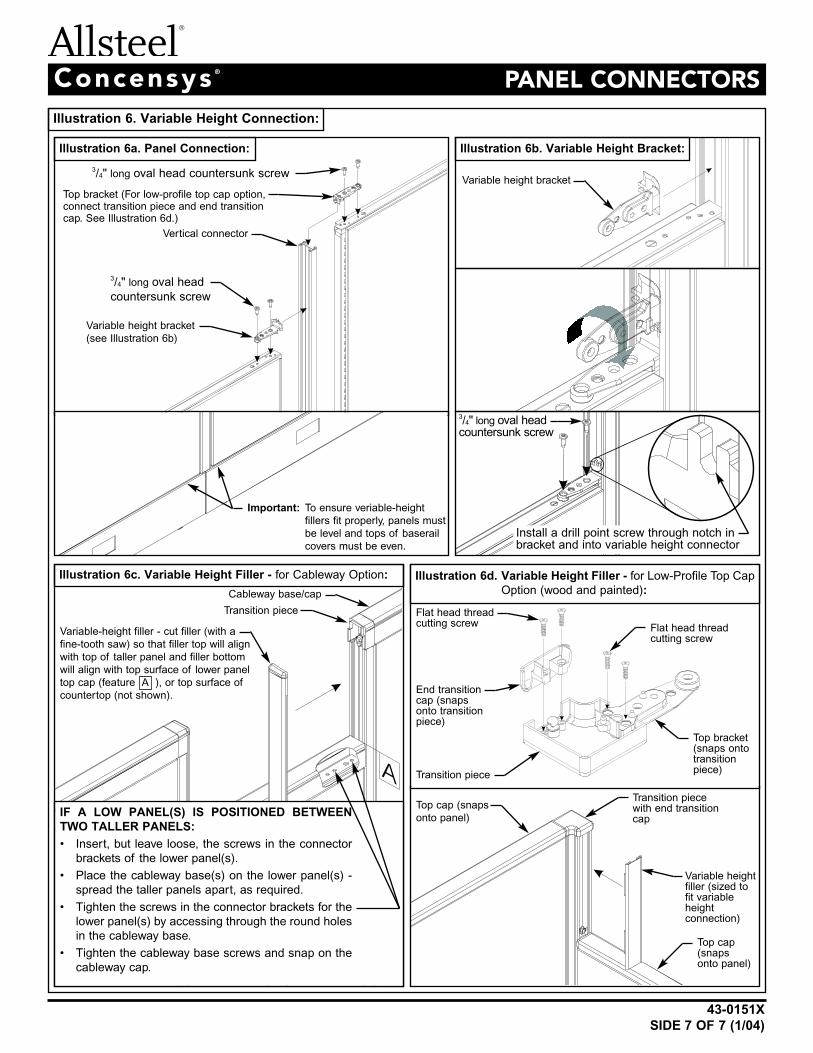
Illustration 6. Variable Height Connection:
Illustration 6a. Panel Connection:
A
Illustration 6c. Variable Height Filler - for Cableway Option:
Illustration 6b. Variable Height Bracket:
Top cap (snaps
onto panel)
Top cap(snapsonto panel)
Variable heightfiller (sized tofit variableheight connection)
Variable-height filler - cut filler (with a
fine-tooth saw) so that filler top will align
with top of taller panel and filler bottom
will align with top surface of lower panel
top cap (feature A ), or top surface of
countertop (not shown).
IF A LOW PANEL(S) IS POSITIONED BETWEEN
TWO TALLER PANELS:
• Insert, but leave loose, the screws in the connector
brackets of the lower panel(s).
• Place the cableway base(s) on the lower panel(s) -
spread the taller panels apart, as required.
• Tighten the screws in the connector brackets for the
lower panel(s) by accessing through the round holes
in the cableway base.
• Tighten the cableway base screws and snap on the
cableway cap.
Cableway base/cap
Transition piece
3/4" long oval head countersunk screw
Install a drill point screw through notch inbracket and into variable height connector
Vertical connector
Variable height bracket
(see Illustration 6b)
Variable height bracket
Top bracket (For low-profile top cap option,connect transition piece and end transitioncap. See Illustration 6d.)
3/4" long oval head
countersunk screw
Transition piecewith end transitioncap
End transitioncap (snapsonto transitionpiece)
Flat head threadcutting screw Flat head thread
cutting screw
Illustration 6d. Variable Height Filler - for Low-Profile Top Cap
Option (wood and painted):
3/4" long oval headcountersunk screw
Top bracket(snaps ontotransitionpiece)
Transition piece
Important: To ensure veriable-height
fillers fit properly, panels must
be level and tops of baserail
covers must be even.

43-0181ESIDE 1 OF 2 (12/00)
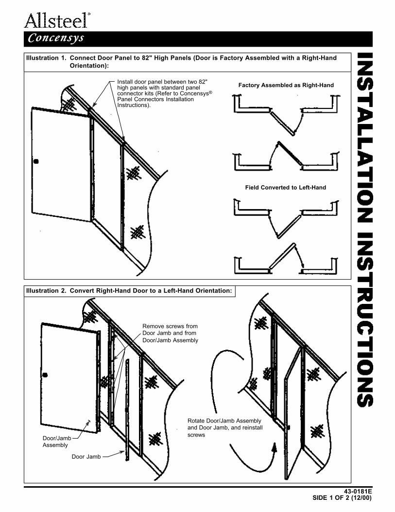
PANELPANEL DOORDOORConcensysConcensys ®®
Illustration 1. Connect Door Panel to 82" High Panels (Door is Factory Assembled with a Right-Hand
Orientation):
Illustration 2. Convert Right-Hand Door to a Left-Hand Orientation:
Install door panel between two 82"high panels with standard panelconnector kits (Refer to Concensys®
Panel Connectors InstallationInstructions).
Factory Assembled as Right-Hand
Field Converted to Left-Hand
Remove screws fromDoor Jamb and from
Door/Jamb Assembly
Door/JambAssembly
Door Jamb
Rotate Door/Jamb Assemblyand Door Jamb, and reinstall
screws
43-0181E
SIDE 2 OF 2 (12/00)
PANELPANEL DOORDOORConcensysConcensys ®®
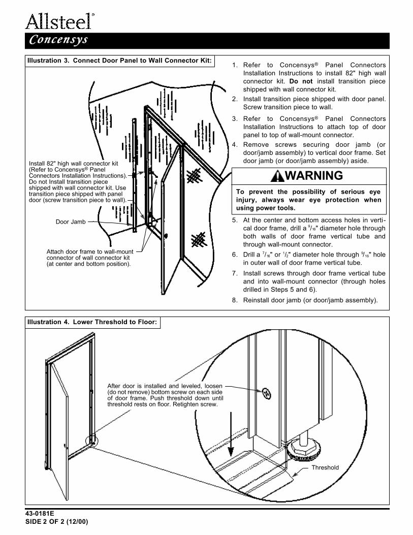
Illustration 3. Connect Door Panel to Wall Connector Kit:
Illustration 4. Lower Threshold to Floor:
Install 82" high wall connector kit(Refer to Concensys® PanelConnectors Installation Instructions).Do not Install transition pieceshipped with wall connector kit. Usetransition piece shipped with paneldoor (screw transition piece to wall).
Door Jamb
Threshold
After door is installed and leveled, loosen(do not remove) bottom screw on each sideof door frame. Push threshold down untilthreshold rests on floor. Retighten screw.
Attach door frame to wall-mountconnector of wall connector kit(at center and bottom position).
1. Refer to Concensys® Panel Connectors
Installation Instructions to install 82" high wall
connector kit. Do not install transition piece
shipped with wall connector kit.
2. Install transition piece shipped with door panel.
Screw transition piece to wall.
3. Refer to Concensys® Panel Connectors
Installation Instructions to attach top of door
panel to top of wall-mount connector.
4. Remove screws securing door jamb (or
door/jamb assembly) to vertical door frame. Set
door jamb (or door/jamb assembly) aside.
5. At the center and bottom access holes in verti-
cal door frame, drill a 9/16" diameter hole through
both walls of door frame vertical tube and
through wall-mount connector.
6. Drill a 7/16" or 1/2" diameter hole through 9/16" hole
in outer wall of door frame vertical tube.
7. Install screws through door frame vertical tube
and into wall-mount connector (through holes
drilled in Steps 5 and 6).
8. Reinstall door jamb (or door/jamb assembly).
To prevent the possibility of serious eye
injury, always wear eye protection when
using power tools.
WARNING
43-0157I(12/00)
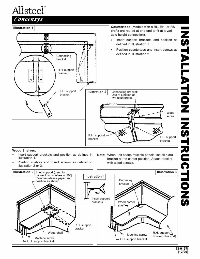
COUNTERTOPS AND WOOD SHELVESCOUNTERTOPS AND WOOD SHELVESConcensysConcensys ®®
Illustration 1
Illustration 2
Illustration 2 Illustration 3
Illustration 1
Connectingbracket
R.H. supportbracket
L.H. supportbracket
Connecting bracket:Use at junction oftwo countertops
R.H. support
bracketL.H. support
bracket
Woodscrew
Countertops (Models with a RL, RH, or RS
prefix are routed at one end to fit at a vari-
able height connection):
• Insert support brackets and position as
defined in Illustration 1.
• Position countertops and insert screws as
defined in Illustration 2.
Wood Shelves:
• Insert support brackets and position as defined inIllustration 1.
• Position shelves and insert screws as defined inIllustration 2 or 3.
Note: When unit spans multiple panels, install extra
bracket at the center position. Attach bracket
with wood screws.
Insert supportbrackets
Shelf support (used to connect two shelves at 90°).Remove release paper andposition as shown.
R.H. supportbracket
Wood shelf
Machine screwL.H. support bracket
R.H. supportbracket (this end)
Machine screw
L.H. support bracket
Wood cornershelf
Corner
bracket

IN
ST
ALLA
TIO
N I
NS
TR
UC
TIO
NS
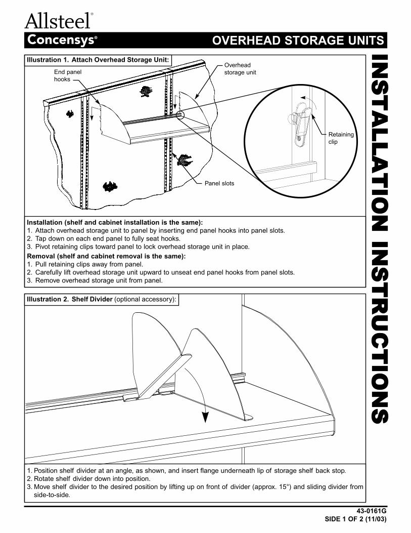
43-0161G
SIDE 1 OF 2 (11/03)
OVERHEAD STORAGE UNITSConcensys®
Installation (shelf and cabinet installation is the same):
1. Attach overhead storage unit to panel by inserting end panel hooks into panel slots.
2. Tap down on each end panel to fully seat hooks.
3. Pivot retaining clips toward panel to lock overhead storage unit in place.
Removal (shelf and cabinet removal is the same):
1. Pull retaining clips away from panel.
2. Carefully lift overhead storage unit upward to unseat end panel hooks from panel slots.
3. Remove overhead storage unit from panel.
Illustration 1. Attach Overhead Storage Unit:
Illustration 2. Shelf Divider (optional accessory):
End panel
hooks
Overhead
storage unit
Panel slots
Retaining
clip
1. Position shelf divider at an angle, as shown, and insert flange underneath lip of storage shelf back stop.
2. Rotate shelf divider down into position.
3. Move shelf divider to the desired position by lifting up on front of divider (approx. 15°) and sliding divider from
side-to-side.
43-0161G
SIDE 2 OF 2 (11/03)
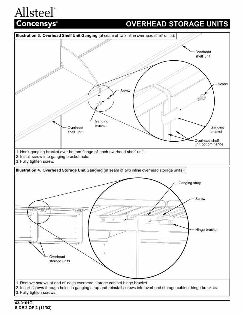
OVERHEAD STORAGE UNITSConcensys®
Illustration 4. Overhead Storage Unit Ganging (at seam of two inline overhead storage units):
Overhead
storage units
Screw
Ganging strap
Hinge bracket
1. Remove screws at end of each overhead storage cabinet hinge bracket.
2. Insert screws through holes in ganging strap and reinstall screws into overhead storage cabinet hinge brackets.
3. Fully tighten screws.
Illustration 3. Overhead Shelf Unit Ganging (at seam of two inline overhead shelf units):
Overhead
shelf unit
Overhead
shelf unit
Screw
Screw
Ganging
bracket
Overhead shelfunit bottom flange
Ganging
bracket
1. Hook ganging bracket over bottom flange of each overhead shelf unit.
2. Install screw into ganging bracket hole.
3. Fully tighten screw.
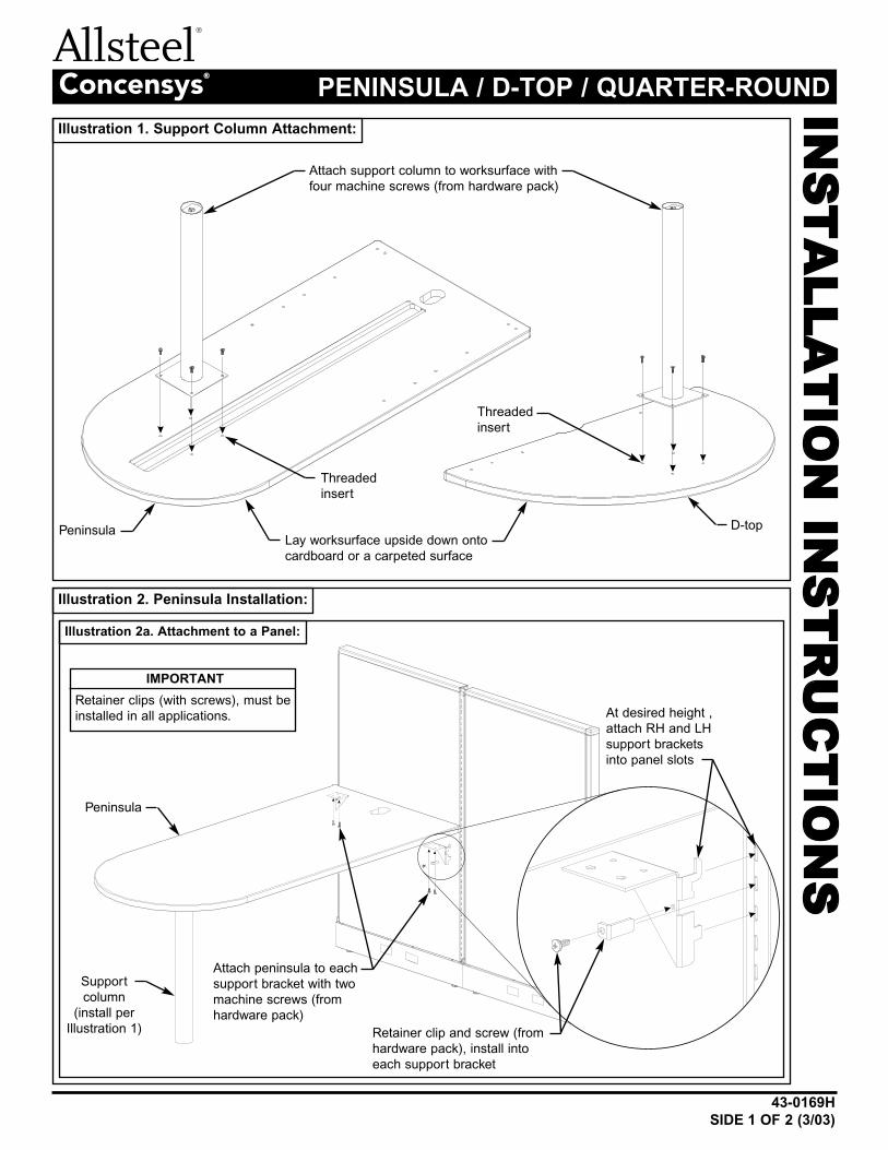
Illustration 2. Peninsula Installation:
IN
ST
ALLA
TIO
N I
NS
TR
UC
TIO
NS
43-0169H
SIDE 1 OF 2 (3/03)
PENINSULA / D-TOP / QUARTER-ROUNDConcensys®
Attach support column to worksurface with
four machine screws (from hardware pack)
Lay worksurface upside down onto
cardboard or a carpeted surface
At desired height ,
attach RH and LH
support brackets
into panel slots
Retainer clip and screw (from
hardware pack), install into
each support bracket
Illustration 1. Support Column Attachment:
IMPORTANT
Retainer clips (with screws), must be
installed in all applications.
Illustration 2a. Attachment to a Panel:
Peninsula
Peninsula D-top
Threaded
insert
Threaded
insert
Support
column
(install per
Illustration 1)
Attach peninsula to each
support bracket with two
machine screws (from
hardware pack)
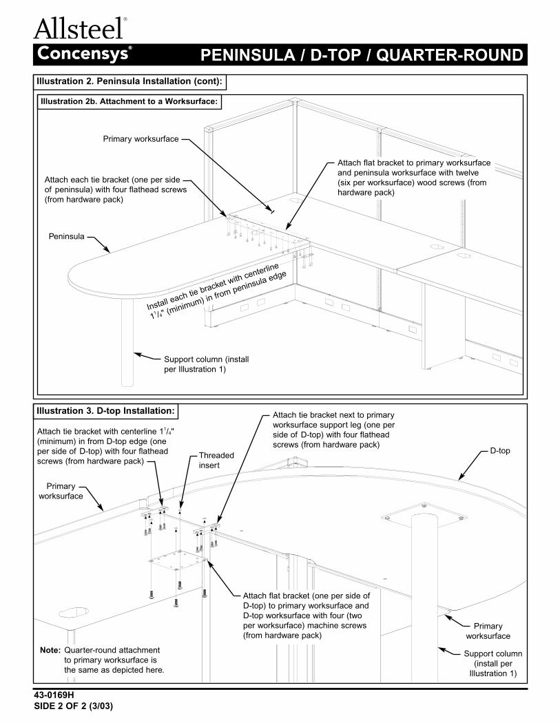
Illustration 3. D-top Installation:
Illustration 2. Peninsula Installation (cont):
Illustration 2b. Attachment to a Worksurface:
43-0169H
SIDE 2 OF 2 (3/03)
PENINSULA / D-TOP / QUARTER-ROUNDConcensys®
Attach flat bracket to primary worksurface
and peninsula worksurface with twelve
(six per worksurface) wood screws (from
hardware pack)
Attach flat bracket (one per side of
D-top) to primary worksurface and
D-top worksurface with four (two
per worksurface) machine screws
(from hardware pack)
Note: Quarter-round attachment
to primary worksurface is
the same as depicted here.
Attach each tie bracket (one per side
of peninsula) with four flathead screws
(from hardware pack)
Attach tie bracket with centerline 11/4"
(minimum) in from D-top edge (one
per side of D-top) with four flathead
screws (from hardware pack)
Attach tie bracket next to primary
worksurface support leg (one per
side of D-top) with four flathead
screws (from hardware pack)
Primary worksurface
Primary
worksurface
Primary
worksurface
Peninsula
D-top
Support column (install
per Illustration 1)
Support column
(install per
Illustration 1)
~
Threaded
insert
Install each tie bracket with centerline
11 /4" (m
inimum) in from peninsula edge
IN
ST
ALLA
TIO
N I
NS
TR
UC
TIO
NS
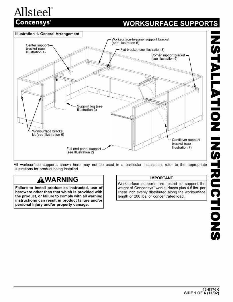
43-0176KSIDE 1 OF 6 (11/02)
Concensys® WORKSURFACE SUPPORTS
All worksurface supports shown here may not be used in a particular installation; refer to the appropriate illustrations for product being installed.
Illustration 1. General Arrangement:
Center supportbracket (seeIllustration 4)
Worksurface-to-panel support bracket(see Illustration 5)
Cantilever supportbracket (seeIllustration 7)
Flat bracket (see Illustration 8)
Corner support bracket(see Illustration 9)
Support leg (seeIllustration 3)
Full end panel support(see Illustration 2)
Worksurface bracketkit (see Illustration 6)
Failure to install product as instructed, use ofhardware other than that which is provided withthe product, or failure to comply with all warninginstructions can result in product failure and/orpersonal injury and/or property damage.
WARNING IMPORTANT
Worksurface supports are tested to support theweight of Concensys® worksurfaces plus 4.5 lbs. perlinear inch evenly distributed along the worksurfacelength or 200 lbs. of concentrated load.
43-0176K
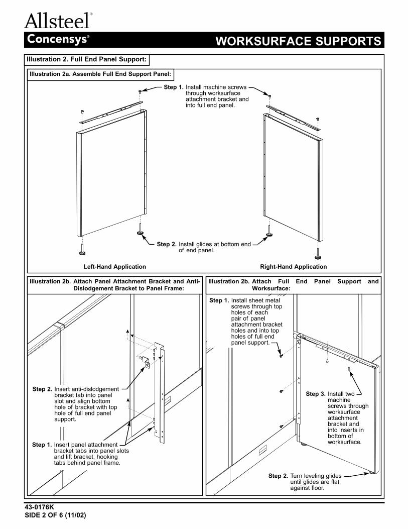
SIDE 2 OF 6 (11/02)
Concensys® WORKSURFACE SUPPORTS
Illustration 2. Full End Panel Support:
Illustration 2a. Assemble Full End Support Panel:
Illustration 2b. Attach Panel Attachment Bracket and Anti-Dislodgement Bracket to Panel Frame:
Left-Hand Application Right-Hand Application
Step 2. Install glides at bottom endof end panel.
Step 1. Install machine screwsthrough worksurfaceattachment bracket andinto full end panel.
Step 3. Install twomachinescrews throughworksurfaceattachmentbracket andinto inserts inbottom ofworksurface.
Step 2. Turn leveling glidesuntil glides are flatagainst floor.
Illustration 2b. Attach Full End Panel Support andWorksurface:
Step 1. Insert panel attachmentbracket tabs into panel slotsand lift bracket, hookingtabs behind panel frame.
Step 1. Install sheet metalscrews through topholes of each pair of panelattachment bracketholes and into topholes of full endpanel support.
Step 2. Insert anti-dislodgementbracket tab into panelslot and align bottomhole of bracket with tophole of full end panelsupport.
43-0176KSIDE 3 OF 6 (11/02)
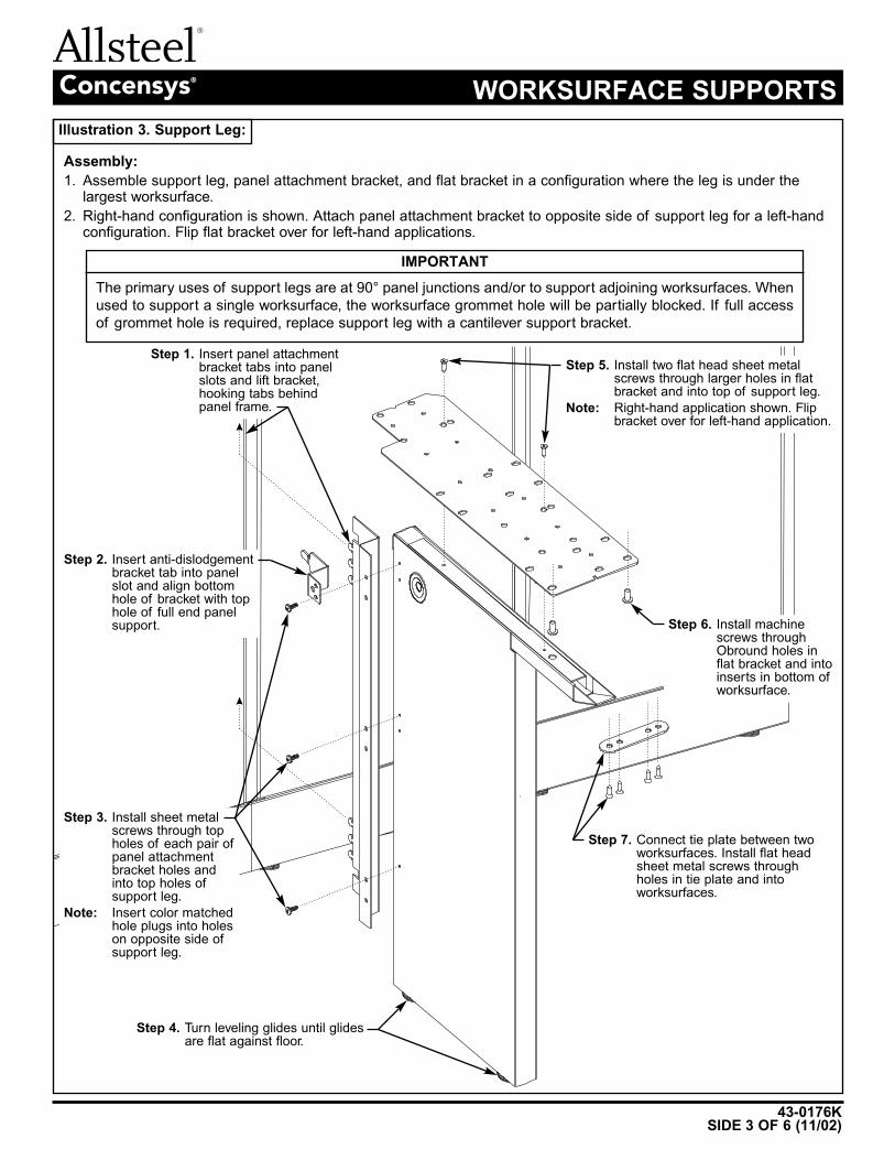
Concensys® WORKSURFACE SUPPORTS
Illustration 3. Support Leg:
Assembly:
1. Assemble support leg, panel attachment bracket, and flat bracket in a configuration where the leg is under thelargest worksurface.
2. Right-hand configuration is shown. Attach panel attachment bracket to opposite side of support leg for a left-handconfiguration. Flip flat bracket over for left-hand applications.
Step 3. Install sheet metalscrews through topholes of each pair ofpanel attachmentbracket holes andinto top holes ofsupport leg.
Note: Insert color matchedhole plugs into holeson opposite side ofsupport leg.
Step 4. Turn leveling glides until glidesare flat against floor.
Step 5. Install two flat head sheet metalscrews through larger holes in flatbracket and into top of support leg.
Note: Right-hand application shown. Flipbracket over for left-hand application.
Step 2. Insert anti-dislodgementbracket tab into panelslot and align bottomhole of bracket with tophole of full end panelsupport.
Step 1. Insert panel attachmentbracket tabs into panelslots and lift bracket,hooking tabs behindpanel frame.
Step 6. Install machinescrews throughObround holes inflat bracket and intoinserts in bottom ofworksurface.
Step 7. Connect tie plate between twoworksurfaces. Install flat headsheet metal screws throughholes in tie plate and intoworksurfaces.
IMPORTANT
The primary uses of support legs are at 90° panel junctions and/or to support adjoining worksurfaces. When
used to support a single worksurface, the worksurface grommet hole will be partially blocked. If full access
of grommet hole is required, replace support leg with a cantilever support bracket.
43-0176K
SIDE 4 OF 6 (11/02)
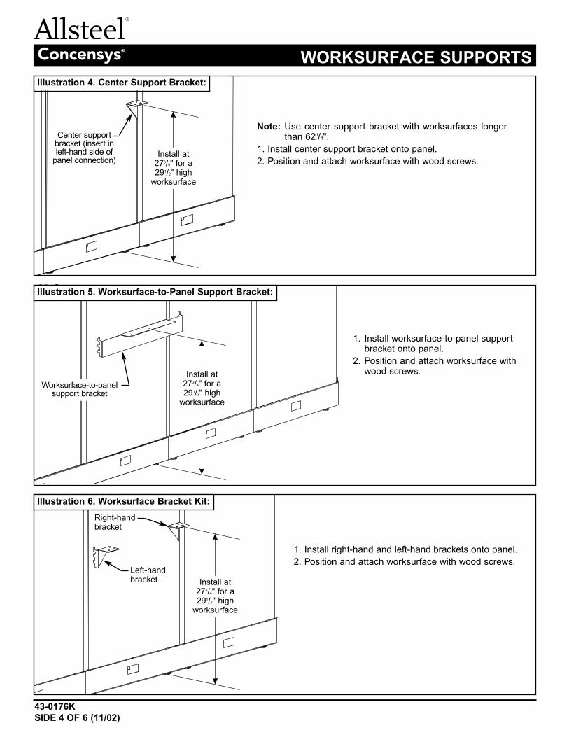
Concensys® WORKSURFACE SUPPORTS
Illustration 5. Worksurface-to-Panel Support Bracket:
Illustration 6. Worksurface Bracket Kit:
Illustration 4. Center Support Bracket:
Note: Use center support bracket with worksurfaces longerthan 621/4".
1. Install center support bracket onto panel.
2. Position and attach worksurface with wood screws.
1. Install worksurface-to-panel supportbracket onto panel.
2. Position and attach worksurface withwood screws.
1. Install right-hand and left-hand brackets onto panel.
2. Position and attach worksurface with wood screws.Left-handbracket
Right-handbracket
Center supportbracket (insert inleft-hand side of
panel connection)
Worksurface-to-panelsupport bracket
Install at273/4" for a291/2" high
worksurface
Install at273/4" for a291/2" high
worksurface
Install at273/4" for a291/2" high
worksurface
43-0176KSIDE 5 OF 6 (11/02)
Concensys® WORKSURFACE SUPPORTS
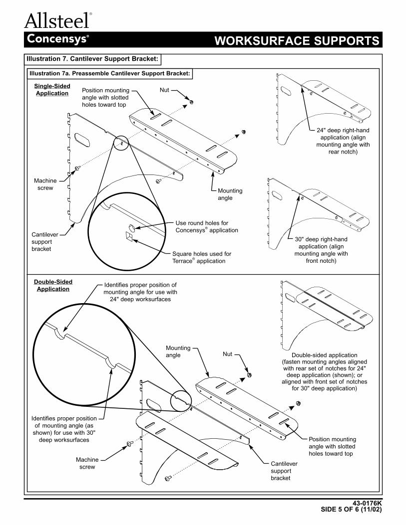
Illustration 7a. Preassemble Cantilever Support Bracket:
Machine
screw
Machine
screw
Single-Sided
Application
Mounting
angle
Nut
Mounting
angle Nut
Cantilever
support
bracket
Double-Sided
Application
24" deep right-hand
application (align
mounting angle with
rear notch)
30" deep right-hand
application (align
mounting angle with
front notch)
Double-sided application(fasten mounting angles alignedwith rear set of notches for 24"
deep application (shown); oraligned with front set of notches
for 30" deep application)
Use round holes for
Concensys®
application
Square holes used for
Terrace®
application
Cantilever
support
bracket
Position mounting
angle with slotted
holes toward top
Identifies proper position
of mounting angle (as
shown) for use with 30"
deep worksurfaces
Identifies proper position of
mounting angle for use with
24" deep worksurfaces
Position mounting
angle with slotted
holes toward top
Illustration 7. Cantilever Support Bracket:
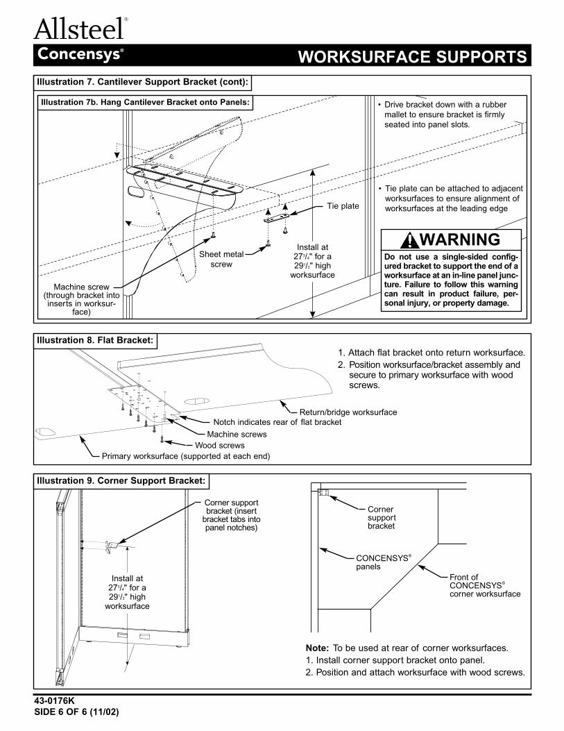
Illustration 7. Cantilever Support Bracket (cont):
43-0176K
SIDE 6 OF 6 (11/02)
Concensys® WORKSURFACE SUPPORTS
Illustration 8. Flat Bracket:
1. Attach flat bracket onto return worksurface.
2. Position worksurface/bracket assembly andsecure to primary worksurface with woodscrews.
Primary worksurface (supported at each end)
Return/bridge worksurface
Machine screws
Wood screws
Notch indicates rear of flat bracket
Illustration 9. Corner Support Bracket:
Note: To be used at rear of corner worksurfaces.
1. Install corner support bracket onto panel.
2. Position and attach worksurface with wood screws.
Corner supportbracket (insert
bracket tabs intopanel notches)
Cornersupportbracket
CONCENSYS®
panels
Front ofCONCENSYS
®
corner worksurface
Illustration 7b. Hang Cantilever Bracket onto Panels:
• Tie plate can be attached to adjacent
worksurfaces to ensure alignment of
worksurfaces at the leading edge
Sheet metal
screw
Machine screw(through bracket intoinserts in worksur-
face)
Tie plate
• Drive bracket down with a rubber
mallet to ensure bracket is firmly
seated into panel slots.
Do not use a single-sided config-ured bracket to support the end of aworksurface at an in-line panel junc-ture. Failure to follow this warningcan result in product failure, per-sonal injury, or property damage.
WARNING
Install at273/4" for a291/2" high
worksurface
Install at273/4" for a291/2" high
worksurface
343-0477E
SIDE 1 OF 6 (7/10)
FlexconnectTM
ELECTRICAL SYSTEM (8-wire)IN
STA
LL
AT
IO
N I
NS
TR
UC
TIO
NS
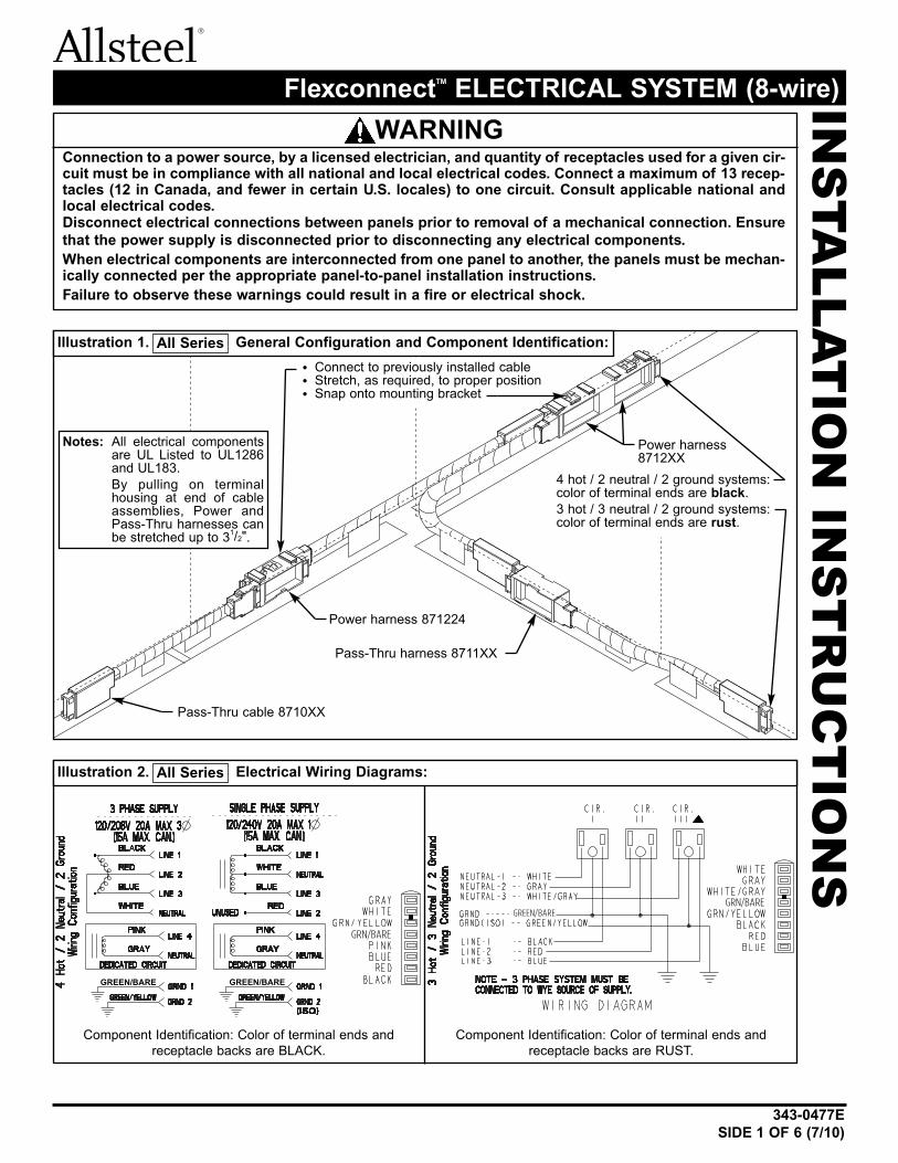
Connection to a power source, by a licensed electrician, and quantity of receptacles used for a given cir-cuit must be in compliance with all national and local electrical codes. Connect a maximum of 13 recep-tacles (12 in Canada, and fewer in certain U.S. locales) to one circuit. Consult applicable national andlocal electrical codes.Disconnect electrical connections between panels prior to removal of a mechanical connection. Ensure
that the power supply is disconnected prior to disconnecting any electrical components.
When electrical components are interconnected from one panel to another, the panels must be mechan-ically connected per the appropriate panel-to-panel installation instructions.
Failure to observe these warnings could result in a fire or electrical shock.
WARNING
All SeriesIllustration 1. General Configuration and Component Identification:
All SeriesIllustration 2. Electrical Wiring Diagrams:
GREEN/BARE GREEN/BARE
GRN/BARE
GRN/BAREGREEN/BARE
Component Identification: Color of terminal ends andreceptacle backs are BLACK.
Component Identification: Color of terminal ends andreceptacle backs are RUST.
Power harness 871224
Power harness8712XX
Notes: All electrical componentsare UL Listed to UL1286and UL183.By pulling on terminalhousing at end of cableassemblies, Power andPass-Thru harnesses canbe stretched up to 31/2".
4 hot / 2 neutral / 2 ground systems:color of terminal ends are black.3 hot / 3 neutral / 2 ground systems:color of terminal ends are rust.
Pass-Thru harness 8711XX
Pass-Thru cable 8710XX
• Connect to previously installed cable• Stretch, as required, to proper position• Snap onto mounting bracket
343-0477E
SIDE 2 OF 6 (7/10)
FlexconnectTM
ELECTRICAL SYSTEM (8-wire)
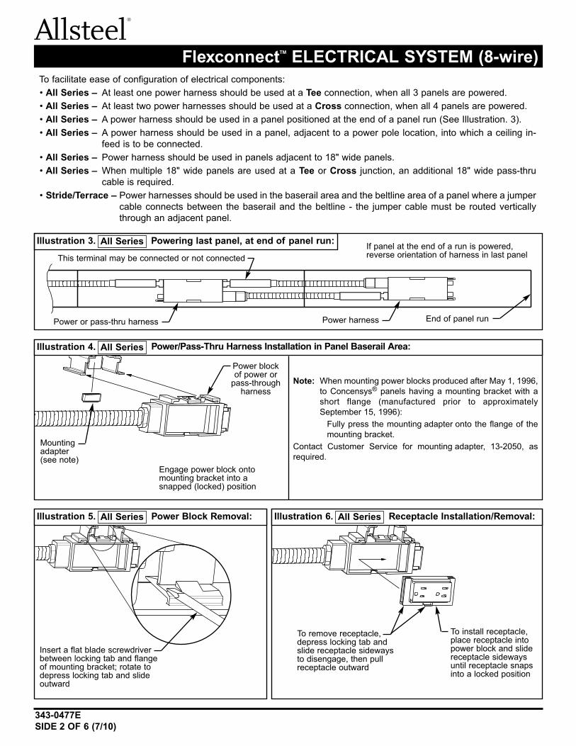
To facilitate ease of configuration of electrical components:• All Series – At least one power harness should be used at a Tee connection, when all 3 panels are powered.• All Series – At least two power harnesses should be used at a Cross connection, when all 4 panels are powered.• All Series – A power harness should be used in a panel positioned at the end of a panel run (See Illustration. 3).• All Series – A power harness should be used in a panel, adjacent to a power pole location, into which a ceiling in-
feed is to be connected.• All Series – Power harness should be used in panels adjacent to 18" wide panels.• All Series – When multiple 18" wide panels are used at a Tee or Cross junction, an additional 18" wide pass-thru
cable is required.• Stride/Terrace – Power harnesses should be used in the baserail area and the beltline area of a panel where a jumper
cable connects between the baserail and the beltline - the jumper cable must be routed verticallythrough an adjacent panel.
Power harness
If panel at the end of a run is powered,reverse orientation of harness in last panel
End of panel run
To install receptacle,place receptacle intopower block and slidereceptacle sidewaysuntil receptacle snapsinto a locked position
To remove receptacle,depress locking tab andslide receptacle sidewaysto disengage, then pullreceptacle outward
Insert a flat blade screwdriverbetween locking tab and flangeof mounting bracket; rotate todepress locking tab and slideoutward
All SeriesIllustration 3. Powering last panel, at end of panel run:
All SeriesIllustration 5. Power Block Removal: All SeriesIllustration 6. Receptacle Installation/Removal:
Power or pass-thru harness
This terminal may be connected or not connected
Engage power block ontomounting bracket into asnapped (locked) position
Mountingadapter(see note)
Power blockof power or
pass-throughharness
Note: When mounting power blocks produced after May 1, 1996,to Concensys® panels having a mounting bracket with ashort flange (manufactured prior to approximatelySeptember 15, 1996):
Fully press the mounting adapter onto the flange of themounting bracket.
Contact Customer Service for mounting adapter, 13-2050, asrequired.
All SeriesIllustration 4. Power/Pass-Thru Harness Installation in Panel Baserail Area:
343-0477E
SIDE 3 OF 6 (7/10)
FlexconnectTM
ELECTRICAL SYSTEM (8-wire)
Power block mount -snap into slots inhorizontal channel
Power block - Snap into
power block
mount
Powerblock
Mounting bracketScrew
For ConcealedReceptacles
For ExposedReceptacles
Terrace®Illustration 7. Panel BeltLine Area Electrical Installation:
Note: When receptacle outletsare concealed within thebeltline area, it is neces-sary to hinge mount beltlinetiles on both sides of panel.
Jumper cable -Route into
adjacent panel,route vertically,then back intosame panel
Alternate routingof jumper cable
Terrace®Illustration 8. BeltLine to Baserail Electrical
Connection:
Sheet metalscrew
Electrical mountingbracket
Spacerbracket
Panel frame horizontalcross member (bottomof a 13" opening)
Terrace®Illustration 9. Electrical Installation in Areas other
than Baserail and Beltline:
Note: Use spacer bracket to mount electricalmounting brackets:• To horizontal frame member at top of belt-
line area of 56" tall and taller panels, and• To any segment kit horizontal member.
CAUTION Terrace® Series
• The interior of panels is NOT to be used for routing electrical cords or extension cords. DO NOT rout cords throughpanel junctions.
• Belt rail tiles must be hinge-mounted on both sides of panel when receptacles outlets are concealed within the beltlinearea.
343-0477E
SIDE 4 OF 6 (7/10)
FlexconnectTM
ELECTRICAL SYSTEM (8-wire)
Illustration 10. Stride Panel Beltline Area Electrical
Installation:
Powerblock
CAUTION• The interior of panels is NOT to be used for routing electrical cords or extension cords. DO NOT rout cords through panel junctions.
Jumper cable - routeinto adjacent panel,vertically, and then
back into samepanel.
Illustration 11. Stride Beltline to Baserail Electrical
Connection:
Use wire tie to securein-feed cable to panelsupport - positionnearest to cableterminal housing
Panel support
Ceiling in-feed cable: model8719(12/18) position powerpole into top of any panel;connect to the end of apower block in an adjacentpanel.
Illustration 12. Stride Ceiling In-Feed Installation into
Baserail Area:
Illustration 13. Stride Ceiling In-Feed Installation into
Beltline Area:
Use wire tie tosecure in-feed cableto horizontal mem-
Ceiling in-feed cable 8719(12/18) –position power pole into top of anypanel; connect to the end of apower block in an adjacent panel.
Mounting bracket kit
PowerBlock
Jumper cable - routeinto adjacent panel,vertically, and thenback into samepanel.
Ceiling in-feed cable: model8719(12/18) position powerpole into top of any panel;connect to the end of a power block in an adjacentpanel.
Use wire tie to securein-feed cable to panelsupport - positionnearest to cableterminal housing
Panel Support
Ceiling in-feed cable: model 8719(12/18)position power pole into top of any panel;connect to the end of a power block in anadjacent panel.
Use wire tie tosecure in-feed cableto horizonal member.
343-0477E
SIDE 5 OF 6 (7/10)
FlexconnectTM
ELECTRICAL SYSTEM (8-wire)
All SeriesIllustration 14. Base or Ceiling Side In-Feed Installation:
Improperly installed electrical components can fail resulting in personal injury and/or property damage.
Connection of the in-feed device to the power source should be performed by a licensed electrician in com-
pliance with all national and local electrical codes.
To prevent personal injury, ensure in-feed power is disconnected before component installation.
WARNING
Illustration 14a. Remove In-Feed Cover:
Illustration 14c. Pass In-Feed Connector Through Baserail
cover:
Illustration 14e. Connect Infeed Connector: Illustration 14f. Reattach In-Feed Cover:
Illustration 14d. Reassemble Swivel Joint:
Illustration 14b. Disconnect Swivel Joint and Remove Swivel
tabs:
In-feed cover - installafter power in-feedand baserail cover isin place
Note: In-feed cable can be shortened. Remove and reapplyUL listing/schematic, near end of cable, as needed.
180° swivel jointSwivel joint - disconnectand hook into in-feedconnector
Swivel joint
In-feed connector
In-feedconnector
In-feed connector
Baserail cover
Baserail cover
Baserail cover
Baserail coverPower block
In-feedconnector
In-feed cover -remove and saveScrew - remove
and save
Screw
Swivel tab - removeand save
Swivel tab
Route cable to power source (refer to wiring diagramon page 1 for proper wiring connections)
343-0477E
SIDE 6 OF 6 (7/10)
FlexconnectTM
ELECTRICAL SYSTEM (8-wire)
8000®SeriesIllustration 15. Ceiling In-Feed Installation into Baserail Area:
Concensys®Illustration 16. Ceiling In-Feed Installation into Baserail Area using Integrated Power Pole (870071):
Note: For information regard-ing installation of powerpoles, refer to theappropriate panelseries Power PoleInstallation Instructions.
Ceiling in-feed cable 8719(12/18) - Power pole can be installed:
Into top of ELL/TEE/CROSS panel junctions where all panels are of equal height, orAt the end of any panel run
Ceiling in-feed cable 8719(12/18) -Position power poleinto top of 90°, Tee, orCross connectors
Panel support
Panel supportUse wire tie to secure in-feed cable to panel support
Plug into powerblock
Use clamp to secure in-feed cable to panelsupport (attach with screw and nut)
Use wire tie to secure in-feedcable to panel support - positionnearest to cable terminal housingPanel support
Plug into Power Block
Ceiling in-feed cable: model8719(12/18) position power pole intotop of any panel; connect to the endof a power block in an adjacent panel
Stride/TerraceIllustration 17. Ceiling In-Feed Installation into Baserail Area:
Terrace®Illustration 18. Ceiling In-Feed Installation into Beltline Area:
Use wire tie to secure in-feed cable to horizontal mem-ber - position through slot in horizontal member
Plug into Power Block
Ceiling in-feed cable 8719(12 or 18) – position power pole into top ofany panel; connect to the end of a power block in an adjacent panel
INSTA
LLATIO
N IN
STRU
CTIO
NS
43-0245BSIDE 1 OF 2 (12/00)
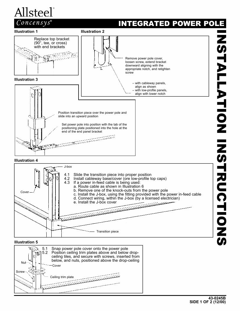
INTEGRATED POWER POLEConcensys ®Illustration 1 Illustration 2
Replace top bracket(90°, tee, or cross)with end brackets
Remove power pole cover,loosen screw, extend bracketdownward aligning with theappropriate notch, and retightenscrew
– with cableway panels,align as shown
– with low-profile panels,align with lower notch
Illustration 3
Illustration 4
Illustration 5
4.1 Slide the transition piece into proper position4.2 Install cableway base/cover (ore low-profile top caps)4.3 If a power in-feed cable is being used:
a. Route cable as shown in Illustration 6b. Remove one of the knock-outs from the power polec. Install the J-box, using the fitting provided with the power in-feed cabled. Connect wiring, within the J-box (by a licensed electrician)e. Install the J-box cover
J-box
Transition piece
Cover
CoverNut
ScrewCeiling trim plate
5.1 Snap power pole cover onto the power pole5.2 Position ceiling trim plates above and below drop-
ceiling tiles, and secure with screws, inserted frombelow, and nuts, positioned above the drop-ceiling
Position transition piece over the power pole andslide into an upward position
Set power pole into position with the tab of thepositioning plate positioned into the hole at theend of the end panel bracket
43-0245BSIDE 2 OF 2 (12/00)
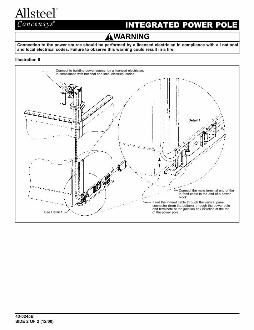
INTEGRATED POWER POLEConcensys ®
Illustration 6
Connection to the power source should be performed by a licensed electrician in compliance with all nationaland local electrical codes. Failure to observe this warning could result in a fire.
Connect to building power source, by a licensed electrician,in compliance with national and local electrical codes
See Detail 1
Detail 1
Feed the in-feed cable through the vertical panel connector (from the bottom), through the power poleand terminate at the junction box installed at the top of the power pole
Connect the male terminal end of thein-feed cable to the end of a powerblock
WARNING
IN
ST
ALLA
TIO
N I
NS
TR
UC
TIO
NS
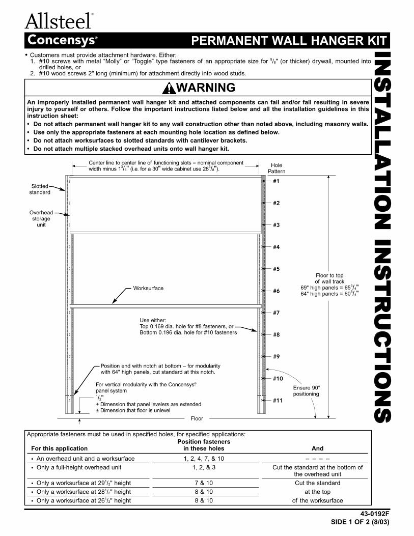
43-0192F
SIDE 1 OF 2 (8/03)
PERMANENT WALL HANGER KITConcensys®
#1
#2
#3
#4
#5
#6
#7
#8
#9
#10
#11
Appropriate fasteners must be used in specified holes, for specified applications:
Position fastenersFor this application in these holes And
• An overhead unit and a worksurface 1, 2, 4, 7, & 10 – – – –
• Only a full-height overhead unit 1, 2, & 3 Cut the standard at the bottom ofthe overhead unit
• Only a worksurface at 291/2" height 7 & 10 Cut the standard
• Only a worksurface at 281/2" height 8 & 10 at the top
• Only a worksurface at 261/2" height 8 & 10 of the worksurface
Floor to topof wall track
69" high panels = 653/4"
64" high panels = 603/4"
Center line to center line of functioning slots = nominal componentwidth minus 1
3/8" (i.e. for a 30" wide cabinet use 285/8").
Use either:Top 0.169 dia. hole for #8 fasteners, orBottom 0.196 dia. hole for #10 fasteners
For vertical modularity with the Concensys®
panel system1/2"+ Dimension that panel levelers are extended± Dimension that floor is unlevel
Position end with notch at bottom – for modularitywith 64" high panels, cut standard at this notch.
Overheadstorage
unit
Worksurface
HolePattern
Floor
Slottedstandard
Ensure 90°positioning
An improperly installed permanent wall hanger kit and attached components can fail and/or fall resulting in severeinjury to yourself or others. Follow the important instructions listed below and all the installation guidelines in thisinstruction sheet:
• Do not attach permanent wall hanger kit to any wall construction other than noted above, including masonry walls.
• Use only the appropriate fasteners at each mounting hole location as defined below.
• Do not attach worksurfaces to slotted standards with cantilever brackets.
• Do not attach multiple stacked overhead units onto wall hanger kit.
WARNING
• Customers must provide attachment hardware. Either;1. #10 screws with metal “Molly” or “Toggle” type fasteners of an appropriate size for 5/8" (or thicker) drywall, mounted into
drilled holes, or2. #10 wood screws 2" long (minimum) for attachment directly into wood studs.
43-0192F
SIDE 2 OF 2 (8/03)
PERMANENT WALL HANGER KITConcensys®
To achieve proper modularity with the Concensys®
Panel System, position slotted standards in relationto wall partitions as shown.
Refer to panel installation instructions for attachment ofpanels to a permanent wall. (Make panel attachmentbefore mounting adjacent wall track.)
9/32"
Note:
When wall tracks interact with panels, vertical
alignment between the two must be ensured.
Center line to center line offunctioning slots = nominal
component width minus 13/8"
(i.e. for a 30" wide cabinetuse 28
5/8").
Center line to center line offunctioning slots = nominal
component width minus 13/8"
(i.e. for a 30" wide cabinetuse 28
5/8").
Center cavitycan be utilizedto conceal tasklight cords.
Side-by-side applications sharea common, center standard.
IN
ST
ALLA
TIO
N I
NS
TR
UC
TIO
NS
43-0601F
SIDE 1 OF 8 (5/03)
FREESTANDING DESK APPLICATIONSCadenceTM
Failure to install product as instructed, use of hardware other than that which is provided with the prod-
uct, or failure to comply with all instructions can result in personal injury.
WARNING
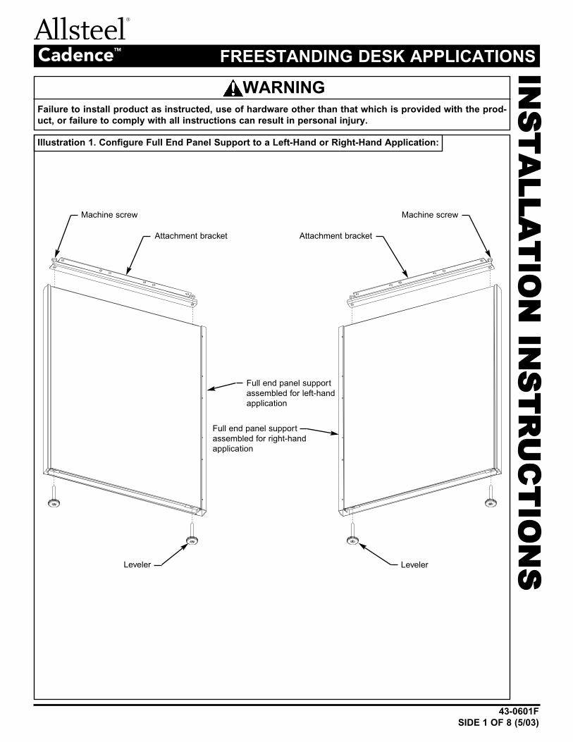
Illustration 1. Configure Full End Panel Support to a Left-Hand or Right-Hand Application:
Full end panel support
assembled for left-hand
application
Full end panel support
assembled for right-hand
application
Attachment bracket
Machine screwMachine screw
Attachment bracket
Leveler Leveler
43-0601F
SIDE 2 OF 8 (5/03)
FREESTANDING DESK APPLICATIONSCadenceTM
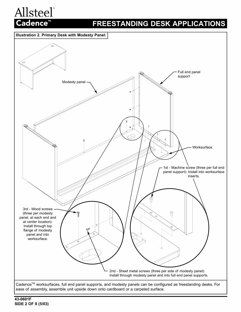
Illustration 2. Primary Desk with Modesty Panel:
Full end panel
support
Modesty panel
Worksurface
3rd - Wood screws
(three per modesty
panel, at each end and
at center location):
Install through top
flange of modesty
panel and into
worksurface.
2nd - Sheet metal screws (three per side of modesty panel):
Install through modesty panel and into full end panel supports.
1st - Machine screw (three per full end
panel support): Install into worksurface
inserts.
CadenceTM worksurfaces, full end panel supports, and modesty panels can be configured as freestanding desks. For
ease of assembly, assemble unit upside down onto cardboard or a carpeted surface.
43-0601F
SIDE 3 OF 8 (5/03)
FREESTANDING DESK APPLICATIONSCadenceTM
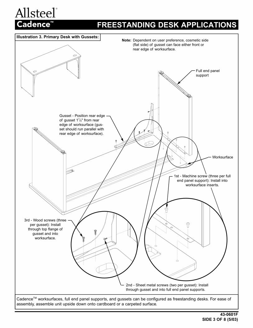
Illustration 3. Primary Desk with Gussets:
Full end panel
support
Gusset - Position rear edge
of gusset 17/8" from rear
edge of worksurface (gus-
set should run parallel with
rear edge of worksurface).
Worksurface
3rd - Wood screws (three
per gusset): Install
through top flange of
gusset and into
worksurface.
2nd - Sheet metal screws (two per gusset): Install
through gusset and into full end panel supports.
1st - Machine screw (three per full
end panel support): Install into
worksurface inserts.
CadenceTM worksurfaces, full end panel supports, and gussets can be configured as freestanding desks. For ease of
assembly, assemble unit upside down onto cardboard or a carpeted surface.
Note: Dependent on user preference, cosmetic side
(flat side) of gusset can face either front or
rear edge of worksurface.
43-0601F
SIDE 4 OF 8 (5/03)
FREESTANDING DESK APPLICATIONSCadenceTM
Illustration 4. Bridge and Return Attachment:
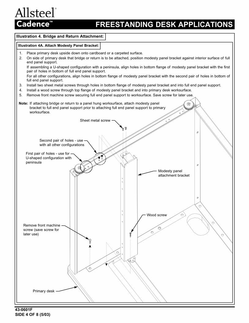
Illustration 4A. Attach Modesty Panel Bracket:
1. Place primary desk upside down onto cardboard or a carpeted surface.
2. On side of primary desk that bridge or return is to be attached, position modesty panel bracket against interior surface of fullend panel support.
If assembling a U-shaped configuration with a peninsula, align holes in bottom flange of modesty panel bracket with the firstpair of holes in bottom of full end panel support.
For all other configurations, align holes in bottom flange of modesty panel bracket with the second pair of holes in bottom offull end panel support.
3. Install two sheet metal screws through holes in bottom flange of modesty panel bracket and into full end panel support.
4. Install a wood screw through top flange of modesty panel bracket and into primary desk worksurface.
5. Remove front machine screw securing full end panel support to worksurface. Save screw for later use.
Modesty panel
attachment bracket
Remove front machine
screw (save screw for
later use)
Sheet metal screw
First pair of holes - use for
U-shaped configuration with
peninsula
Second pair of holes - use
with all other configurations
Wood screw
Primary desk
Note: If attaching bridge or return to a panel hung worksurface, attach modesty panel
bracket to full end panel support prior to attaching full end panel support to primary
worksurface.
43-0601F
SIDE 5 OF 8 (5/03)
FREESTANDING DESK APPLICATIONSCadenceTM
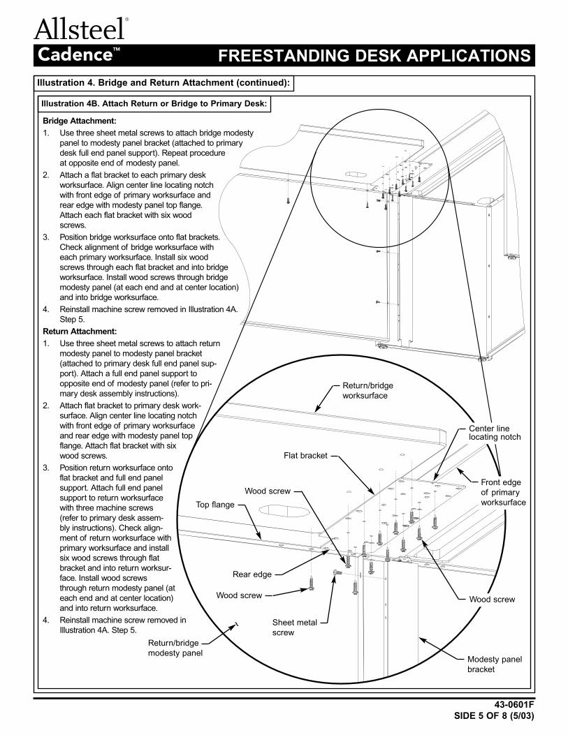
Illustration 4. Bridge and Return Attachment (continued):
Illustration 4B. Attach Return or Bridge to Primary Desk:
Bridge Attachment:
1. Use three sheet metal screws to attach bridge modesty
panel to modesty panel bracket (attached to primary
desk full end panel support). Repeat procedure
at opposite end of modesty panel.
2. Attach a flat bracket to each primary desk
worksurface. Align center line locating notch
with front edge of primary worksurface and
rear edge with modesty panel top flange.
Attach each flat bracket with six wood
screws.
3. Position bridge worksurface onto flat brackets.
Check alignment of bridge worksurface with
each primary worksurface. Install six wood
screws through each flat bracket and into bridge
worksurface. Install wood screws through bridge
modesty panel (at each end and at center location)
and into bridge worksurface.
4. Reinstall machine screw removed in Illustration 4A.
Step 5.
Return Attachment:
1. Use three sheet metal screws to attach return
modesty panel to modesty panel bracket
(attached to primary desk full end panel sup-
port). Attach a full end panel support to
opposite end of modesty panel (refer to pri-
mary desk assembly instructions).
2. Attach flat bracket to primary desk work-
surface. Align center line locating notch
with front edge of primary worksurface
and rear edge with modesty panel top
flange. Attach flat bracket with six
wood screws.
3. Position return worksurface onto
flat bracket and full end panel
support. Attach full end panel
support to return worksurface
with three machine screws
(refer to primary desk assem-
bly instructions). Check align-
ment of return worksurface with
primary worksurface and install
six wood screws through flat
bracket and into return worksur-
face. Install wood screws
through return modesty panel (at
each end and at center location)
and into return worksurface.
4. Reinstall machine screw removed in
Illustration 4A. Step 5.Sheet metal
screw
Wood screwWood screw
Center linelocating notch
Front edge
of primary
worksurface
Wood screw
Flat bracket
Return/bridge
worksurface
Return/bridge
modesty panelModesty panel
bracket
~
Rear edge
Top flange
43-0601F
SIDE 6 OF 8 (5/03)
FREESTANDING DESK APPLICATIONSCadenceTM
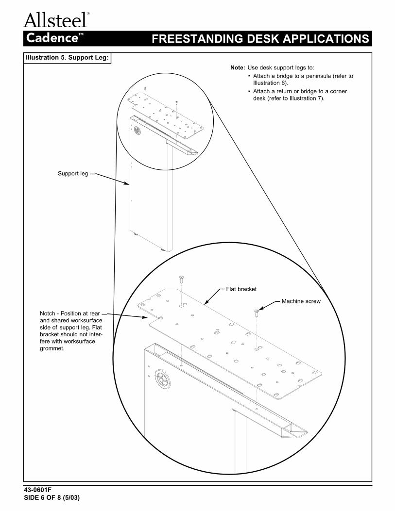
Illustration 5. Support Leg:
Flat bracket
Machine screw
Notch - Position at rear
and shared worksurface
side of support leg. Flat
bracket should not inter-
fere with worksurface
grommet.
Support leg
Note: Use desk support legs to:
· Attach a bridge to a peninsula (refer to
Illustration 6).
· Attach a return or bridge to a corner
desk (refer to Illustration 7).
43-0601F
SIDE 7 OF 8 (5/03)
FREESTANDING DESK APPLICATIONSCadenceTM
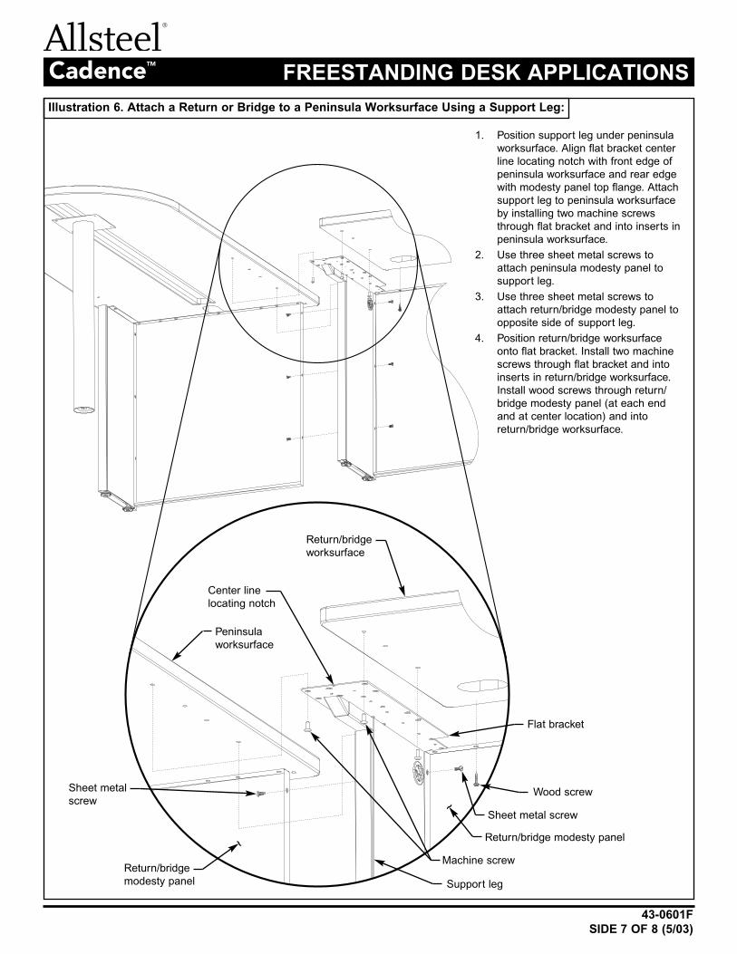
Illustration 6. Attach a Return or Bridge to a Peninsula Worksurface Using a Support Leg:
1. Position support leg under peninsula
worksurface. Align flat bracket center
line locating notch with front edge of
peninsula worksurface and rear edge
with modesty panel top flange. Attach
support leg to peninsula worksurface
by installing two machine screws
through flat bracket and into inserts in
peninsula worksurface.
2. Use three sheet metal screws to
attach peninsula modesty panel to
support leg.
3. Use three sheet metal screws to
attach return/bridge modesty panel to
opposite side of support leg.
4. Position return/bridge worksurface
onto flat bracket. Install two machine
screws through flat bracket and into
inserts in return/bridge worksurface.
Install wood screws through return/
bridge modesty panel (at each end
and at center location) and into
return/bridge worksurface.
Sheet metal
screw
Sheet metal screw
Wood screw
Center line
locating notch
Peninsula
worksurface
Machine screw
Flat bracket
Return/bridge
worksurface
Return/bridge
modesty panel
Return/bridge modesty panel
Support leg
~
~
43-0601F
SIDE 8 OF 8 (5/03)
FREESTANDING DESK APPLICATIONSCadenceTM
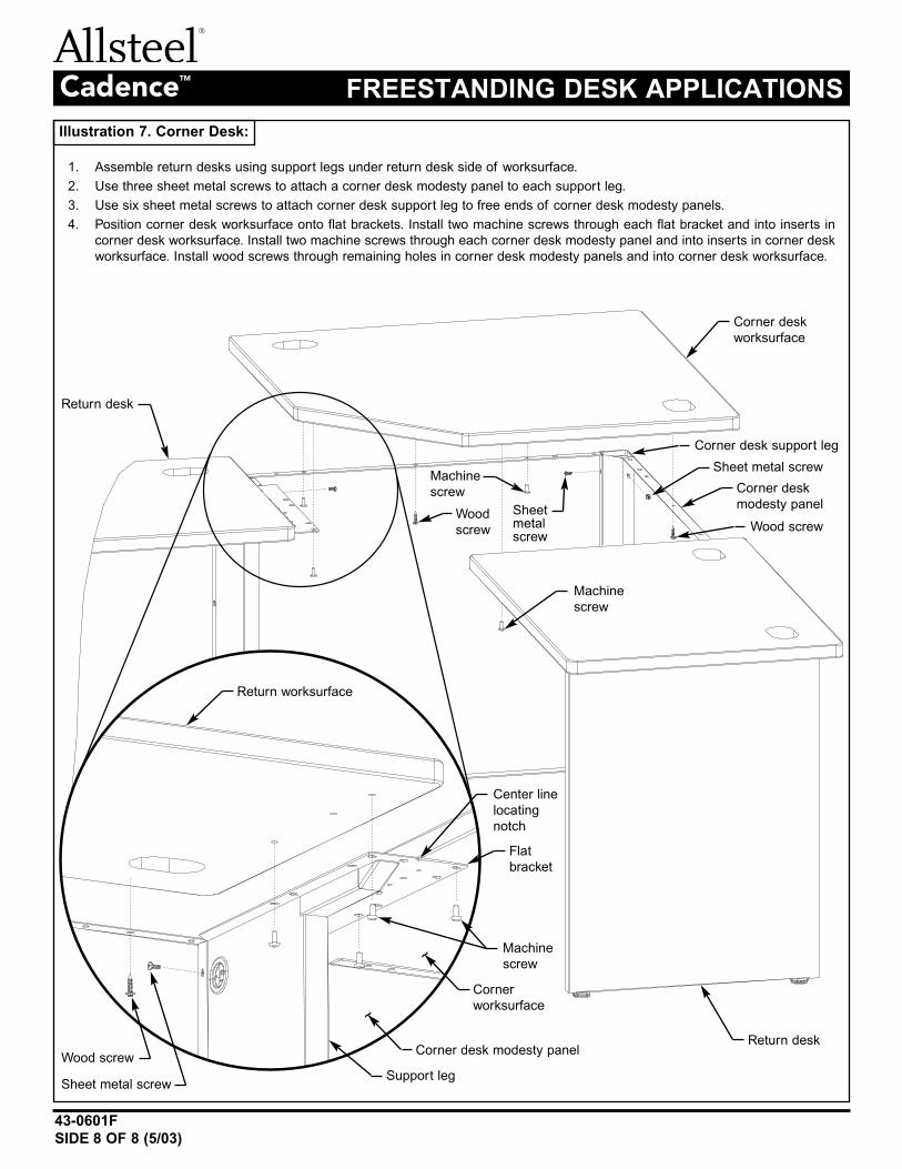
Illustration 7. Corner Desk:
1. Assemble return desks using support legs under return desk side of worksurface.
2. Use three sheet metal screws to attach a corner desk modesty panel to each support leg.
3. Use six sheet metal screws to attach corner desk support leg to free ends of corner desk modesty panels.
4. Position corner desk worksurface onto flat brackets. Install two machine screws through each flat bracket and into inserts in
corner desk worksurface. Install two machine screws through each corner desk modesty panel and into inserts in corner desk
worksurface. Install wood screws through remaining holes in corner desk modesty panels and into corner desk worksurface.
Sheet metal screw
Sheet metal screw
Sheetmetalscrew
Wood screw
Wood screw
Corner desk support leg
Machine
screw
Machine
screw
Corner desk
worksurface
Corner desk modesty panel
Corner desk
modesty panel
Support leg
Wood
screw
Machine
screw
Corner
worksurface
Return worksurface
Return desk
Return desk
Center line
locating
notch
Flat
bracket
~
~
Worksurface Placement
• Panel will function with worksurfaces positioned at any of the
offered heights.
• Data and electrical ports are always located above worksurfaces.
Commercially Available Data Modules designed to fit a 1.37 x
2.68 opening can be used with a grommet.
Pass Through Power Harness can be used if one port is to be
used as a data port, or if only one receptacle is used.
Routing Electrical Harness from Adjacent Panel:
1. Remove tiles from one side of panel frames.
2. Route electrical harness through slots in sides of panel
frames and through vertical connector. Note: Route electrical
harness around light block strip (do not remove, tear, or dam-
age light block strip).
Jumping from Baserail to Beltline Area:
1. Remove all tiles from panel frame.
2. Route electrical jumper through slots in panel frame horizontal
member.
Concensys®
INSTALLATION INSTRUCTIONS
TECHNOLOGY PANEL
343-0217D(11/07)
Models: 991XXXX (porting on
one side, as depicted)
992XXXX (porting on
both sides)
NOTE
Refer to Concensys® Panel Connectors Instruction Sheet 43-0151 for panel-to-
panel connections, and for additional information concerning electrical installation,
refer to the installation instructions provided with electrical components.
Topcap
Top
Tile
Beltline
Cover
Bottom
Tile
Figure 1
Figure 8
Figure 10
2
3
4
Top
Tile
Clip
Intermediate
Tile
Clip
Bottom
Tile
Clip
Figure 7
Power and Data
Management
Note:
When setting up a
configuration as shown
in Figure 9, you can not
use the data port in the
kickplate on either side,
due to electrical conduit
interference.
Note:
An alternative set-up
would be to use a jumper
from the base and pick
of the power block you
do not plan on running
data through. (Figure 10)
Note:
A CDP kit is also an option
for data when these electrical
situations are unavoidable.
Tile Removal/Replacement:
1. When removing the tile below beltline,
it is necessary to remove the beltline
cover. (Figure 2-4) (topcap also needs
to be disassemble from the panel to
remove all other tiles)
2. Slide the tile upward to disengage the
bottom & intermediate tile clips.
3. Pull the bottom of the tile away
from the panel.
4. Slide the tile down to disengage the
top tile clips.
Figure 2
Beltline cover notch
Figure 3
Insert kickplate tool
into beltline cover notch
Figure 4
Rotate kickplate tool
down to disengage
the tops of both sides
of the beltline cover
Figure 5
To reinstall beltline
cover, align beltline
cover slot with cover
bracket on panel. Snap
cover into place.
Beltline
Cover
Bracket
Beltline
Cover
Slot
Beltline
Cover
Notch
Figure 9

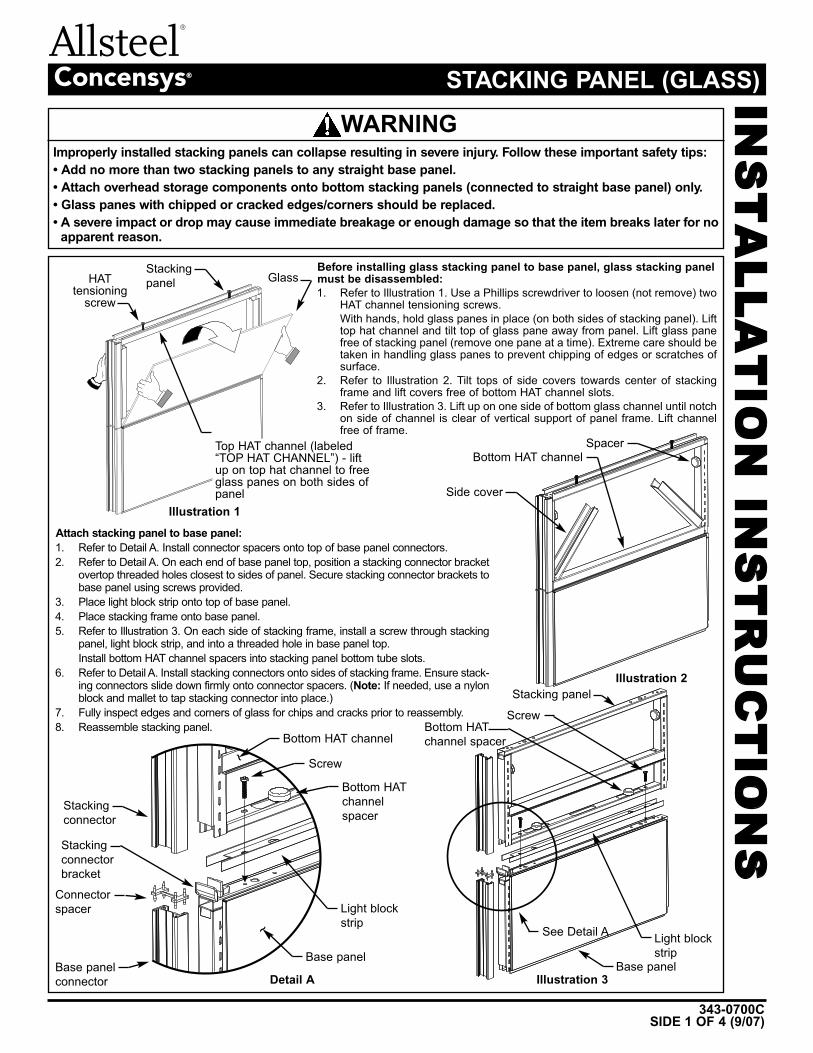
Concensys®INSTALLATION INSTRUCTIONS
STACKING PANEL (GLASS)
343-0700CSIDE 1 OF 4 (9/07)
Improperly installed stacking panels can collapse resulting in severe injury. Follow these important safety tips:
• Add no more than two stacking panels to any straight base panel.
• Attach overhead storage components onto bottom stacking panels (connected to straight base panel) only.
• Glass panes with chipped or cracked edges/corners should be replaced.
• A severe impact or drop may cause immediate breakage or enough damage so that the item breaks later for noapparent reason.
WARNING
Before installing glass stacking panel to base panel, glass stacking panelmust be disassembled:
1. Refer to Illustration 1. Use a Phillips screwdriver to loosen (not remove) twoHAT channel tensioning screws.With hands, hold glass panes in place (on both sides of stacking panel). Lifttop hat channel and tilt top of glass pane away from panel. Lift glass panefree of stacking panel (remove one pane at a time). Extreme care should betaken in handling glass panes to prevent chipping of edges or scratches ofsurface.
2. Refer to Illustration 2. Tilt tops of side covers towards center of stackingframe and lift covers free of bottom HAT channel slots.
3. Refer to Illustration 3. Lift up on one side of bottom glass channel until notchon side of channel is clear of vertical support of panel frame. Lift channelfree of frame.
Attach stacking panel to base panel:
1. Refer to Detail A. Install connector spacers onto top of base panel connectors.2. Refer to Detail A. On each end of base panel top, position a stacking connector bracket
overtop threaded holes closest to sides of panel. Secure stacking connector brackets tobase panel using screws provided.
3. Place light block strip onto top of base panel.4. Place stacking frame onto base panel.5. Refer to Illustration 3. On each side of stacking frame, install a screw through stacking
panel, light block strip, and into a threaded hole in base panel top.Install bottom HAT channel spacers into stacking panel bottom tube slots.
6. Refer to Detail A. Install stacking connectors onto sides of stacking frame. Ensure stack-ing connectors slide down firmly onto connector spacers. (Note: If needed, use a nylonblock and mallet to tap stacking connector into place.)
7. Fully inspect edges and corners of glass for chips and cracks prior to reassembly.8. Reassemble stacking panel.
HATtensioning
screwGlass
Top HAT channel (labeled“TOP HAT CHANNEL”) - liftup on top hat channel to freeglass panes on both sides ofpanel
Stackingpanel
Stacking panel
Stackingconnectorbracket
Stackingconnector
Bottom HAT channelScrew
Bottom HATchannelspacer
Light blockstrip
Base panelDetail A
Illustration 1
Illustration 2
Illustration 3
Connectorspacer
Base panelconnector
Bottom HATchannel spacer
Light blockstrip
Base panel
See Detail A
Screw
Side cover
Bottom HAT channelSpacer
~
~
343-0700C
SIDE 2 OF 4 (9/07)
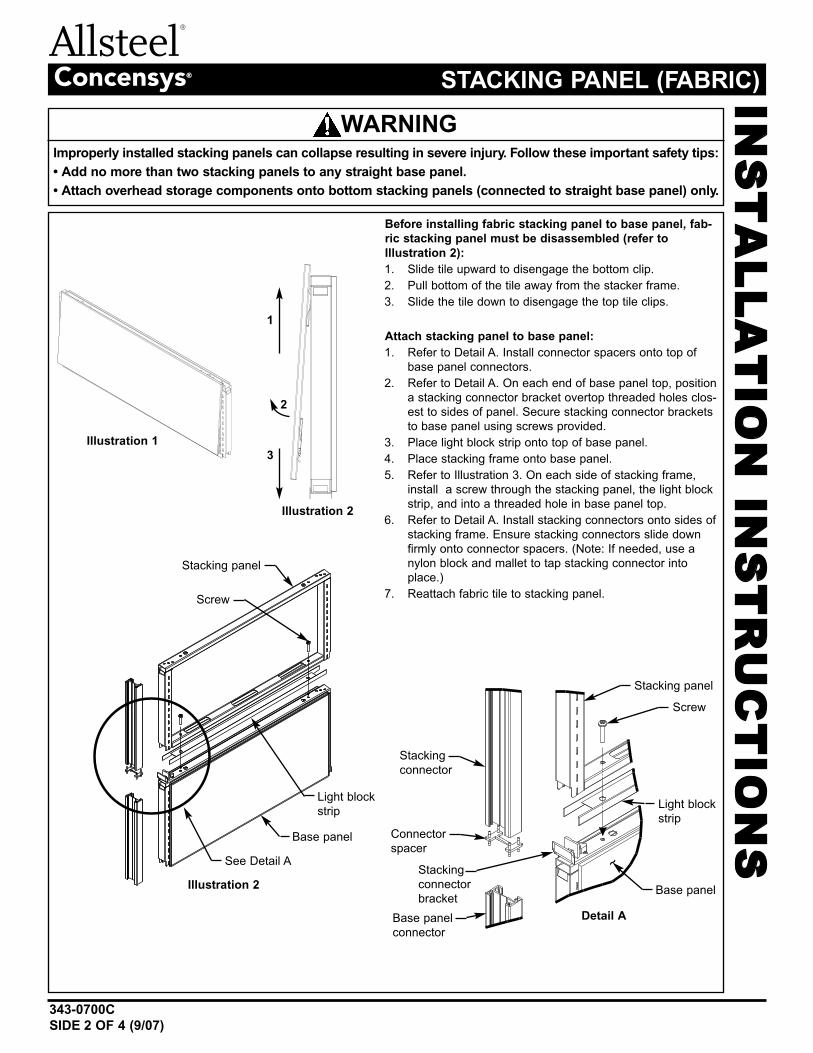
Concensys® STACKING PANEL (FABRIC)
Improperly installed stacking panels can collapse resulting in severe injury. Follow these important safety tips:
• Add no more than two stacking panels to any straight base panel.
• Attach overhead storage components onto bottom stacking panels (connected to straight base panel) only.
WARNING
Before installing fabric stacking panel to base panel, fab-
ric stacking panel must be disassembled (refer to
Illustration 2):
1. Slide tile upward to disengage the bottom clip.2. Pull bottom of the tile away from the stacker frame.3. Slide the tile down to disengage the top tile clips.
Attach stacking panel to base panel:
1. Refer to Detail A. Install connector spacers onto top ofbase panel connectors.
2. Refer to Detail A. On each end of base panel top, positiona stacking connector bracket overtop threaded holes clos-est to sides of panel. Secure stacking connector bracketsto base panel using screws provided.
3. Place light block strip onto top of base panel.4. Place stacking frame onto base panel.5. Refer to Illustration 3. On each side of stacking frame,
install a screw through the stacking panel, the light blockstrip, and into a threaded hole in base panel top.
6. Refer to Detail A. Install stacking connectors onto sides ofstacking frame. Ensure stacking connectors slide downfirmly onto connector spacers. (Note: If needed, use anylon block and mallet to tap stacking connector intoplace.)
7. Reattach fabric tile to stacking panel.Stacking panel
Stackingconnectorbracket
Stackingconnector
Stacking panelScrew
Light blockstrip
Base panelDetail A
Illustration 2
Connectorspacer
Base panelconnector
Light blockstrip
Base panelSee Detail A
Screw
~
INSTALLATION INSTRUCTIONS
Illustration 1
1
Illustration 2
2
3
343-0700CSIDE 3 OF 4 (9/07)
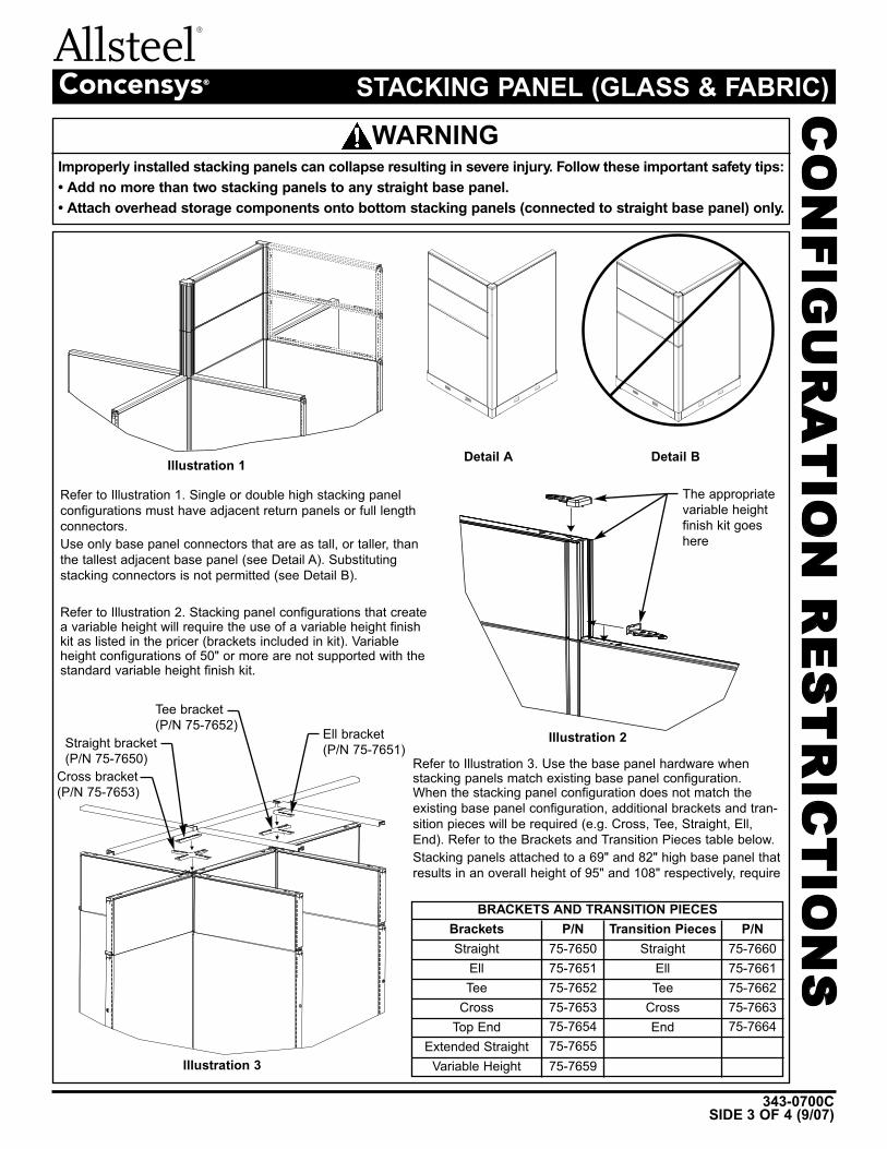
Concensys® STACKING PANEL (GLASS & FABRIC)
Improperly installed stacking panels can collapse resulting in severe injury. Follow these important safety tips:
• Add no more than two stacking panels to any straight base panel.
• Attach overhead storage components onto bottom stacking panels (connected to straight base panel) only.
WARNING
CONFIGURATION RESTRICTIONS
Illustration 1Detail A Detail B
Illustration 2
Illustration 3
Refer to Illustration 1. Single or double high stacking panelconfigurations must have adjacent return panels or full lengthconnectors.Use only base panel connectors that are as tall, or taller, thanthe tallest adjacent base panel (see Detail A). Substitutingstacking connectors is not permitted (see Detail B).
Refer to Illustration 2. Stacking panel configurations that createa variable height will require the use of a variable height finishkit as listed in the pricer (brackets included in kit). Variableheight configurations of 50" or more are not supported with thestandard variable height finish kit.
Refer to Illustration 3. Use the base panel hardware whenstacking panels match existing base panel configuration.When the stacking panel configuration does not match theexisting base panel configuration, additional brackets and tran-sition pieces will be required (e.g. Cross, Tee, Straight, Ell,End). Refer to the Brackets and Transition Pieces table below.Stacking panels attached to a 69" and 82" high base panel thatresults in an overall height of 95" and 108" respectively, require
BRACKETS AND TRANSITION PIECES
Brackets Transition Pieces
Straight Straight75-7650 75-766075-766175-766275-766375-7664
75-765175-765275-765375-765475-765575-7659
P/N P/N
Ell EllTee Tee
Cross CrossEndTop End
Extended StraightVariable Height
The appropriatevariable heightfinish kit goeshere
Ell bracket(P/N 75-7651)
Tee bracket(P/N 75-7652)
Straight bracket(P/N 75-7650)
Cross bracket(P/N 75-7653)
343-0700C
SIDE 4 OF 4 (9/07)
Concensys® STACKING PANEL (GLASS & FABRIC)
Improperly installed stacking panels can collapse resulting in severe injury. Follow these important safety tips:
• Add no more than two stacking panels to any straight base panel.
• Attach overhead storage components onto bottom stacking panels (connected to straight base panel) only.
WARNING
CONFIGURATION RESTRICTIONS
Illustration 4
Illustration 5
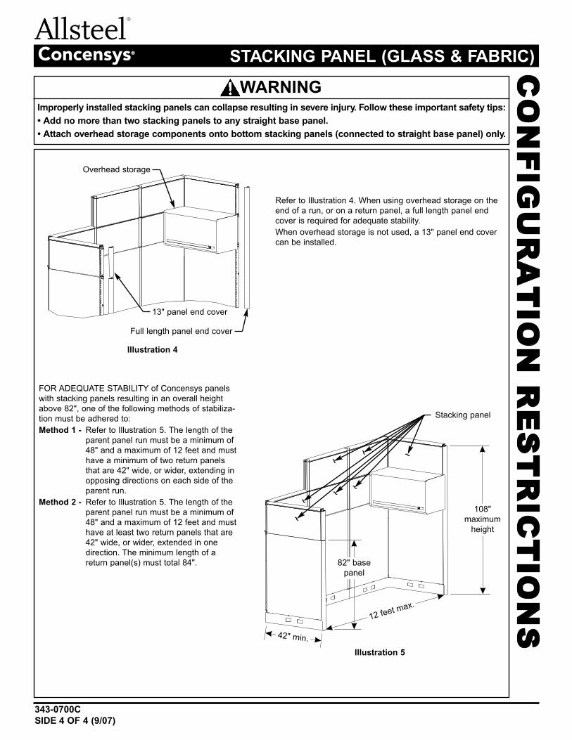
Refer to Illustration 4. When using overhead storage on theend of a run, or on a return panel, a full length panel endcover is required for adequate stability.When overhead storage is not used, a 13" panel end covercan be installed.
FOR ADEQUATE STABILITY of Concensys panelswith stacking panels resulting in an overall heightabove 82", one of the following methods of stabiliza-tion must be adhered to:Method 1 - Refer to Illustration 5. The length of the
parent panel run must be a minimum of48" and a maximum of 12 feet and musthave a minimum of two return panelsthat are 42" wide, or wider, extending inopposing directions on each side of theparent run.
Method 2 - Refer to Illustration 5. The length of theparent panel run must be a minimum of48" and a maximum of 12 feet and musthave at least two return panels that are42" wide, or wider, extended in onedirection. The minimum length of areturn panel(s) must total 84".
Overhead storage
Stacking panel
Full length panel end cover
42" min.
12 feet max.
82" basepanel
108"maximum
height
13" panel end cover
~~~
~~~~


2210 Second Avenue
Muscatine, IA 52761-5257
70-0010
06/07/11