Embed Size (px)
Citation preview
1© Presented at NACMA • September 17-18, 2009 – Dr. Greg Hetland
Dr. Greg Hetland, President Dr. Greg Hetland, President –– [email protected]@iigdt.com
www.iigdt.comwww.iigdt.com
Implications of Complex Surface Geometries and Tight Tolerances on Manufacturing & Metrology
International Institute of GD&TInternational Institute of GD&T
IIGDT
Presented at “NACMA”September 17, 2009
2© Presented at NACMA • September 17-18, 2009 – Dr. Greg Hetland
Complex surface geometries and decreasing feature tolerances are driving the need for unprecedented precision in product design definition and identifying Profile Tolerancing as “the” solution for future dimensioning and tolerancing practices for
mechanical components and assemblies. This presentation will highlight limitations in common (+/-) tolerancing schemes and
will show how Profile Tolerancing provides the basis for precision tolerancing on the engineering drawings and precision
measurement in manufacturing and metrology.
Abstract:
© Presented at NACMA • September 17-18, 2009 – Dr. Greg Hetland 33
Technology Challenges & Constraints• Miniaturization & Tolerance Truncation
• Cycle-time Competing with Precision Requirements
Business Challenges & Constraints• Decreasing Profit Margins
• Tolerances Decreasing - Bad Decisions Increasing
High-Risk Issues• Inability for designers to represent functional intent through
engineering drawings and specifications.• Individuals not trained optimally to manufacture and inspect
product to engineering drawings and specification (Includes tooling, fixtures and equipment)
Business & Technology Constraints
4© Presented at NACMA • September 17-18, 2009 – Dr. Greg Hetland
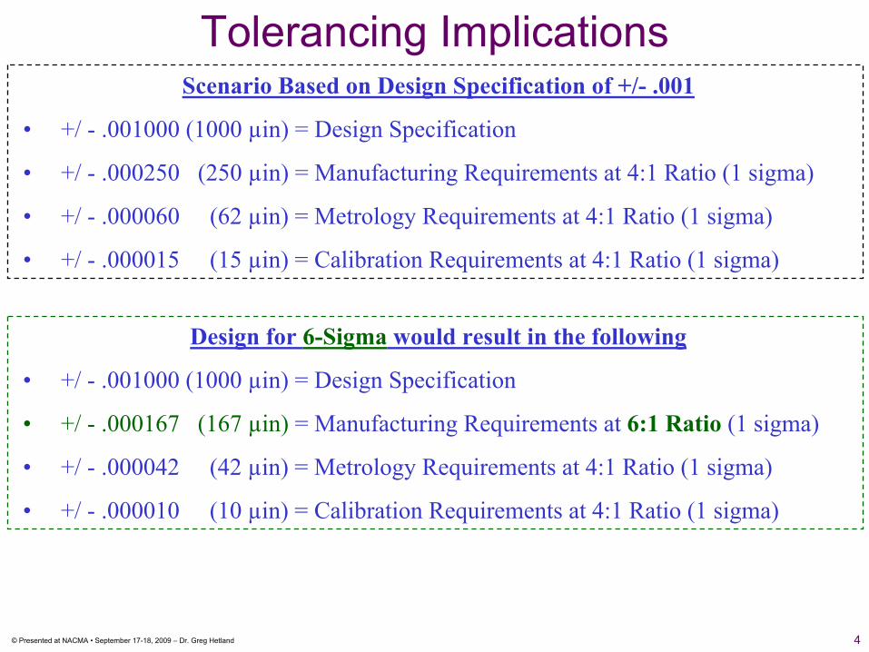
Tolerancing ImplicationsScenario Based on Design Specification of +/- .001
• +/ - .001000 (1000 µin) = Design Specification
• +/ - .000250 (250 µin) = Manufacturing Requirements at 4:1 Ratio (1 sigma)
• +/ - .000060 (62 µin) = Metrology Requirements at 4:1 Ratio (1 sigma)
• +/ - .000015 (15 µin) = Calibration Requirements at 4:1 Ratio (1 sigma)
Design for 6-Sigma would result in the following
• +/ - .001000 (1000 µin) = Design Specification
• +/ - .000167 (167 µin) = Manufacturing Requirements at 6:1 Ratio (1 sigma)
• +/ - .000042 (42 µin) = Metrology Requirements at 4:1 Ratio (1 sigma)
• +/ - .000010 (10 µin) = Calibration Requirements at 4:1 Ratio (1 sigma)
© Presented at NACMA • September 17-18, 2009 – Dr. Greg Hetland 55
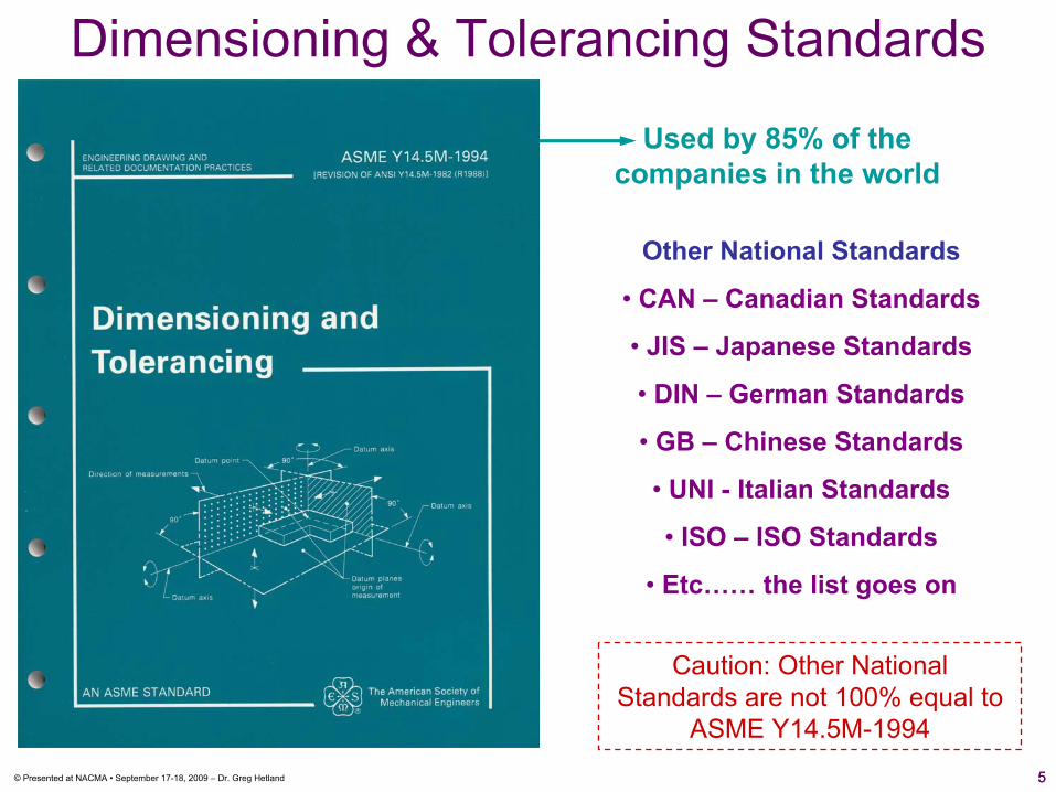
Dimensioning & Tolerancing Standards
Other National Standards
• CAN – Canadian Standards
• JIS – Japanese Standards
• DIN – German Standards
• GB – Chinese Standards
• UNI - Italian Standards
• ISO – ISO Standards
• Etc…… the list goes on
Used by 85% of the companies in the world
Caution: Other National Standards are not 100% equal to
ASME Y14.5M-1994

6© Presented at NACMA • September 17-18, 2009 – Dr. Greg Hetland
[Ö|).)%]
Outer BoundaryInner Boundary
0.05
[Ö|).)%]
Outer BoundaryInner Boundary
0.05
Profile “ASME Y14.5” -vs- “ISO 1101”
© Presented at NACMA • September 17-18, 2009 – Dr. Greg Hetland 77
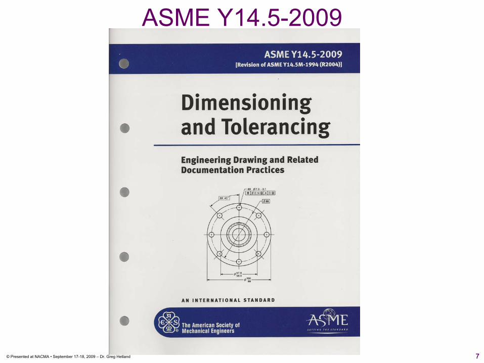
ASME Y14.5-2009

© Presented at NACMA • September 17-18, 2009 – Dr. Greg Hetland 88
ASME Y14.5 - Rule #1
50 ± 0.1
25 ± 0.1
49.9
24.9
50.1
25.1
“Perceived” inner and outer
boundaries
What are the derived boundaries you envision for the 25 +/- 0.1 & 50 +/- 0.1?
Red boundaries do not represent worst case allowable boundaries
© Presented at NACMA • September 17-18, 2009 – Dr. Greg Hetland 99
25.124.9
24.9
24.9
Rule #1
25 ± 0.1 24.9 25.1
24.925.1
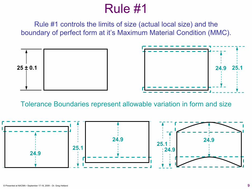
Rule #1 controls the limits of size (actual local size) and theboundary of perfect form at it’s Maximum Material Condition (MMC).
Tolerance Boundaries represent allowable variation in form and size
© Presented at NACMA • September 17-18, 2009 – Dr. Greg Hetland 1010
49.9
50.1
49.9
Rule #1
50 ± 0.1 49.950.1
49.950.1
49.950.1
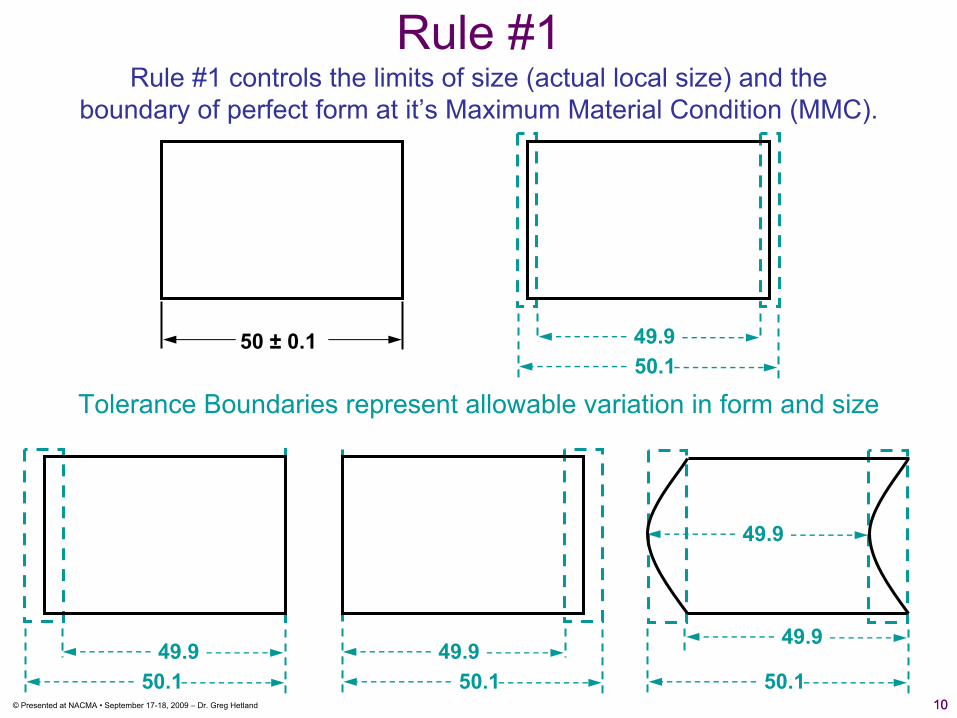
Tolerance Boundaries represent allowable variation in form and size
Rule #1 controls the limits of size (actual local size) and theboundary of perfect form at it’s Maximum Material Condition (MMC).
11© Presented at NACMA • September 17-18, 2009 – Dr. Greg Hetland
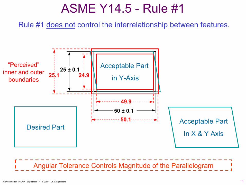
Desired Part
ASME Y14.5 - Rule #1Rule #1 does not control the interrelationship between features.
50 ± 0.1
25 ± 0.1
49.9
24.9
50.1
25.1
Acceptable Part
In X & Y Axis
“Perceived” inner and outer
boundaries
Acceptable Part
in Y-Axis
Angular Tolerance Controls Magnitude of the Parallelogram
12© Presented at NACMA • September 17-18, 2009 – Dr. Greg Hetland
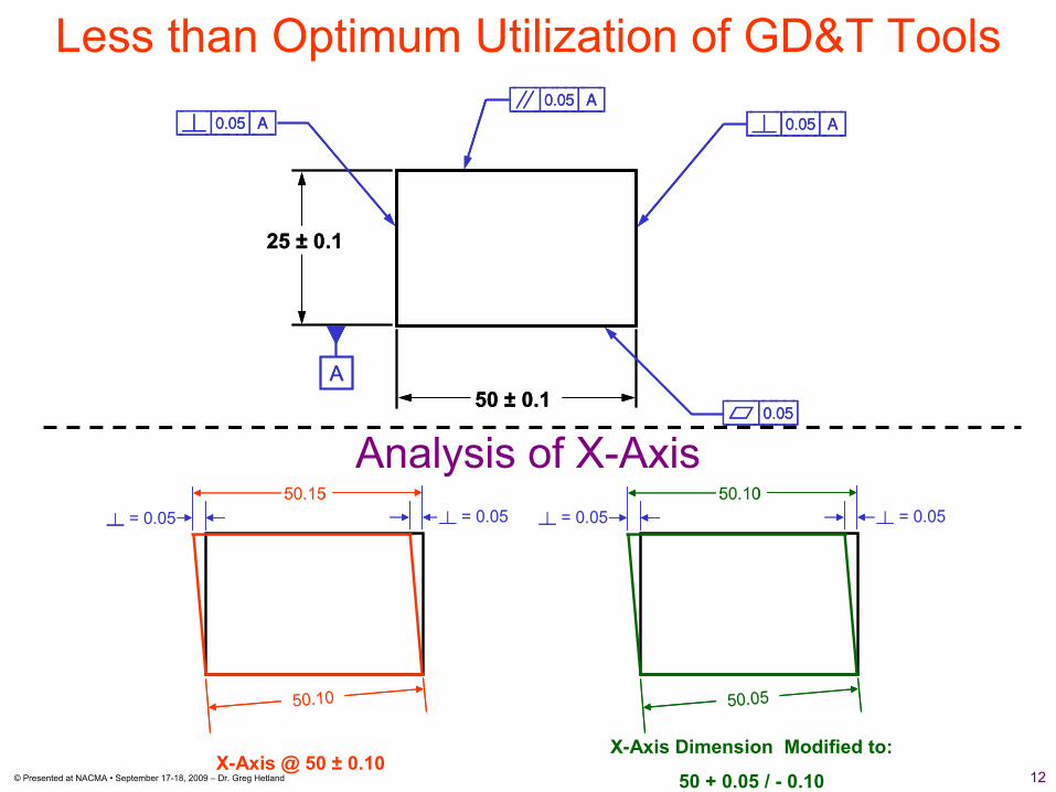
Less than Optimum Utilization of GD&T Tools
Analysis of X-Axis
50.1050.10
Ë = 0.05Ë = 0.0550.1550.15
50.0550.05
50.1050.10
X-Axis @ 50 ± 0.10X-Axis Dimension Modified to:
50 + 0.05 / - 0.10
Ë = 0.05Ë = 0.05 Ë = 0.05Ë = 0.05 Ë = 0.05Ë = 0.05
50 ± 0.1
25 ± 0.1
[â|).)%|A][à|).)%|A] [à|).)%|A]
[Å|).)%]
A50 ± 0.1
25 ± 0.1
[â|).)%|A][à|).)%|A] [à|).)%|A]
[Å|).)%]
A

13© Presented at NACMA • September 17-18, 2009 – Dr. Greg Hetland
Precision GD&T
[Ö|).!]0.1
50
25
“Profile Tolerancing Controls Simple and Complex Geometries”
14© Presented at NACMA • September 17-18, 2009 – Dr. Greg Hetland
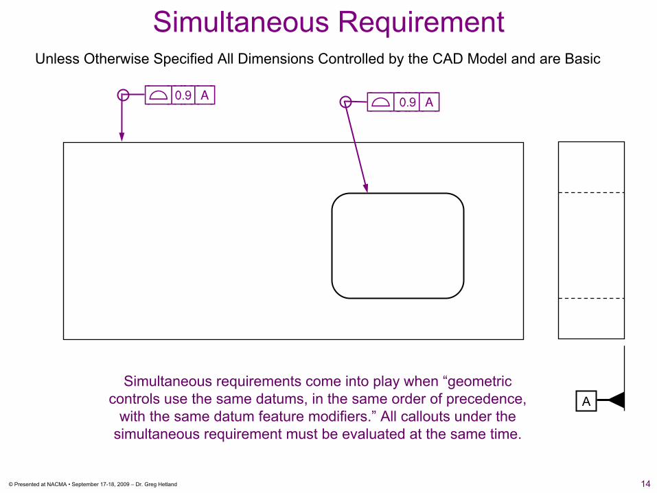
Unless Otherwise Specified All Dimensions Controlled by the CAD Model and are Basic
Simultaneous Requirement
A
[Ö|).(|A] [Ö|::).(|A]
Simultaneous requirements come into play when “geometric controls use the same datums, in the same order of precedence,
with the same datum feature modifiers.” All callouts under the simultaneous requirement must be evaluated at the same time.
15© Presented at NACMA • September 17-18, 2009 – Dr. Greg Hetland
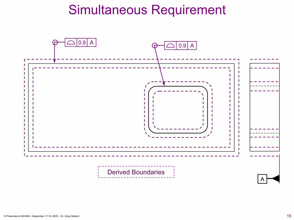
Simultaneous Requirement
A
[Ö|).(|A] [Ö|::).(|A]
Derived Boundaries
16© Presented at NACMA • September 17-18, 2009 – Dr. Greg Hetland
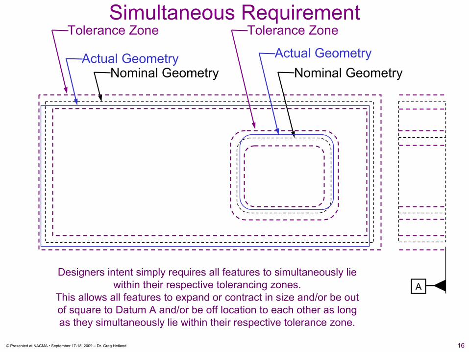
Simultaneous Requirement
Nominal GeometryNominal Geometry
Tolerance Zone Tolerance Zone
Actual GeometryActual Geometry
ADesigners intent simply requires all features to simultaneously lie
within their respective tolerancing zones. This allows all features to expand or contract in size and/or be out of square to Datum A and/or be off location to each other as long as they simultaneously lie within their respective tolerance zone.

17© Presented at NACMA • September 17-18, 2009 – Dr. Greg Hetland
Unless Otherwise Specified All Dimensions Controlled by the CAD Model and are Basic
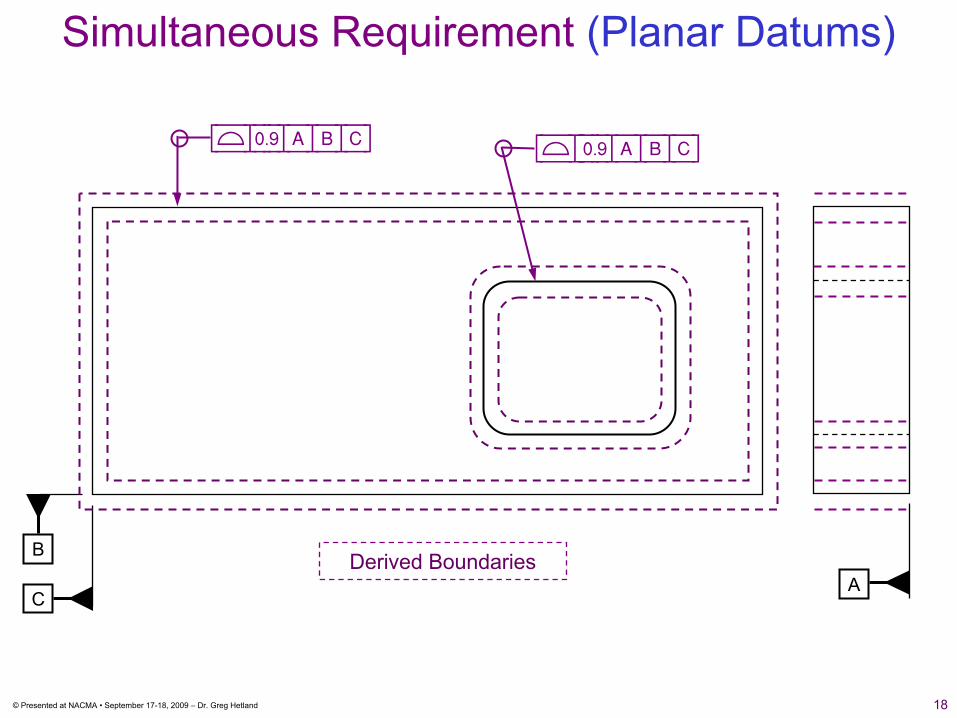
Simultaneous Requirement (Planar Datums)
AC
B
[Ö|).(|A|B|C] [Ö|::).(|A|B|C]
Potential Problem with Datum’s B & C
18© Presented at NACMA • September 17-18, 2009 – Dr. Greg Hetland
Simultaneous Requirement (Planar Datums)
AC
B
[Ö|).(|A|B|C] [Ö|::).(|A|B|C]
Derived Boundaries
19© Presented at NACMA • September 17-18, 2009 – Dr. Greg Hetland
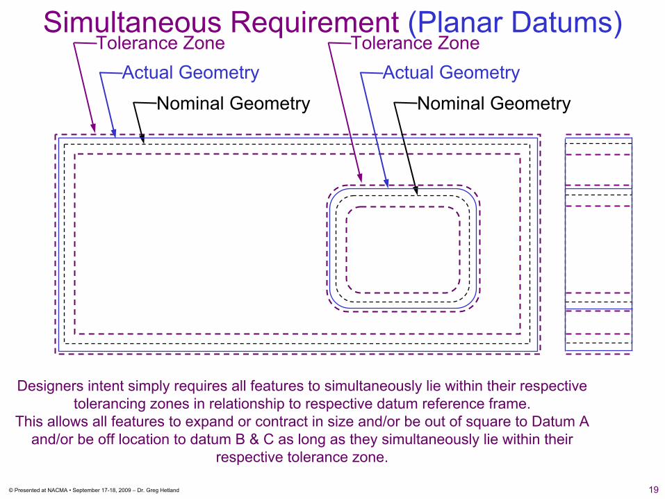
Nominal Geometry
Actual Geometry
Nominal Geometry
Tolerance Zone Tolerance ZoneActual Geometry
Simultaneous Requirement (Planar Datums)
Designers intent simply requires all features to simultaneously lie within their respective tolerancing zones in relationship to respective datum reference frame.
This allows all features to expand or contract in size and/or be out of square to Datum A and/or be off location to datum B & C as long as they simultaneously lie within their
respective tolerance zone.
20© Presented at NACMA • September 17-18, 2009 – Dr. Greg Hetland
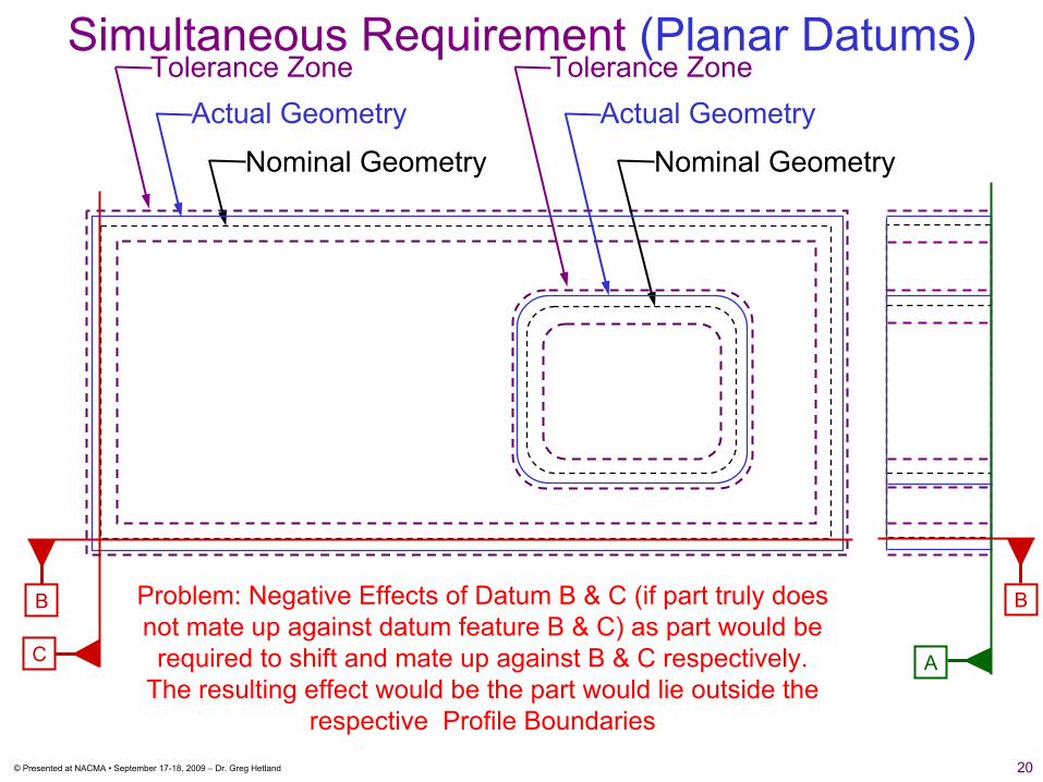
Nominal GeometryNominal Geometry
Tolerance Zone Tolerance ZoneActual Geometry Actual Geometry
C
B B
A
Simultaneous Requirement (Planar Datums)
Problem: Negative Effects of Datum B & C (if part truly does not mate up against datum feature B & C) as part would be
required to shift and mate up against B & C respectively. The resulting effect would be the part would lie outside the
respective Profile Boundaries
21© Presented at NACMA • September 17-18, 2009 – Dr. Greg Hetland
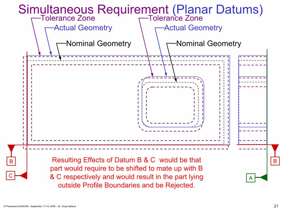
Nominal GeometryNominal Geometry
Tolerance Zone Tolerance ZoneActual Geometry Actual Geometry
C
B B
A
Resulting Effects of Datum B & C would be that part would require to be shifted to mate up with B & C respectively and would result in the part lying
outside Profile Boundaries and be Rejected.
Simultaneous Requirement (Planar Datums)
22© Presented at NACMA • September 17-18, 2009 – Dr. Greg Hetland
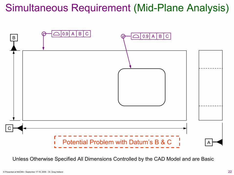
Unless Otherwise Specified All Dimensions Controlled by the CAD Model and are Basic
Simultaneous Requirement (Mid-Plane Analysis)
A
[Ö|).(|A|B|C] [Ö|::).(|A|B|C]B
C
Potential Problem with Datum’s B & C
23© Presented at NACMA • September 17-18, 2009 – Dr. Greg Hetland
A
[Ö|).(|A|B|C] [Ö|::).(|A|B|C]B
C
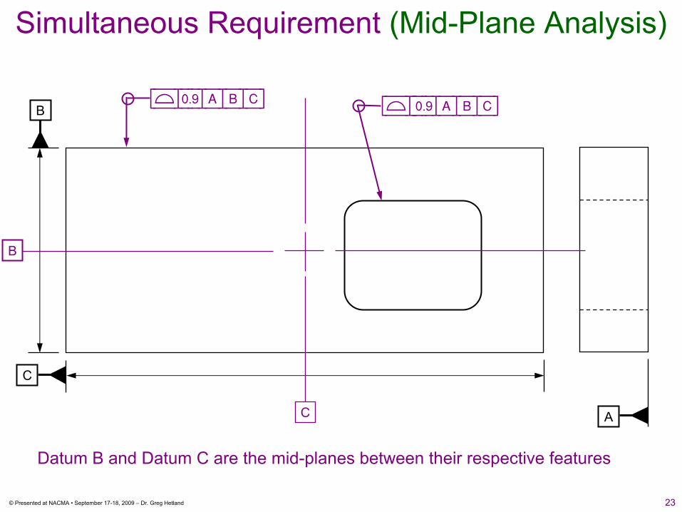
Datum B and Datum C are the mid-planes between their respective features
B
C
Simultaneous Requirement (Mid-Plane Analysis)
24© Presented at NACMA • September 17-18, 2009 – Dr. Greg Hetland
A
[Ö|).(|A|B|C] [Ö|::).(|A|B|C]B
C
B
C
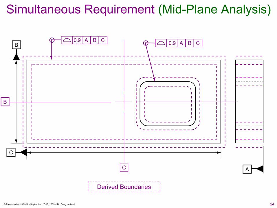
Simultaneous Requirement (Mid-Plane Analysis)
Derived Boundaries
25© Presented at NACMA • September 17-18, 2009 – Dr. Greg Hetland
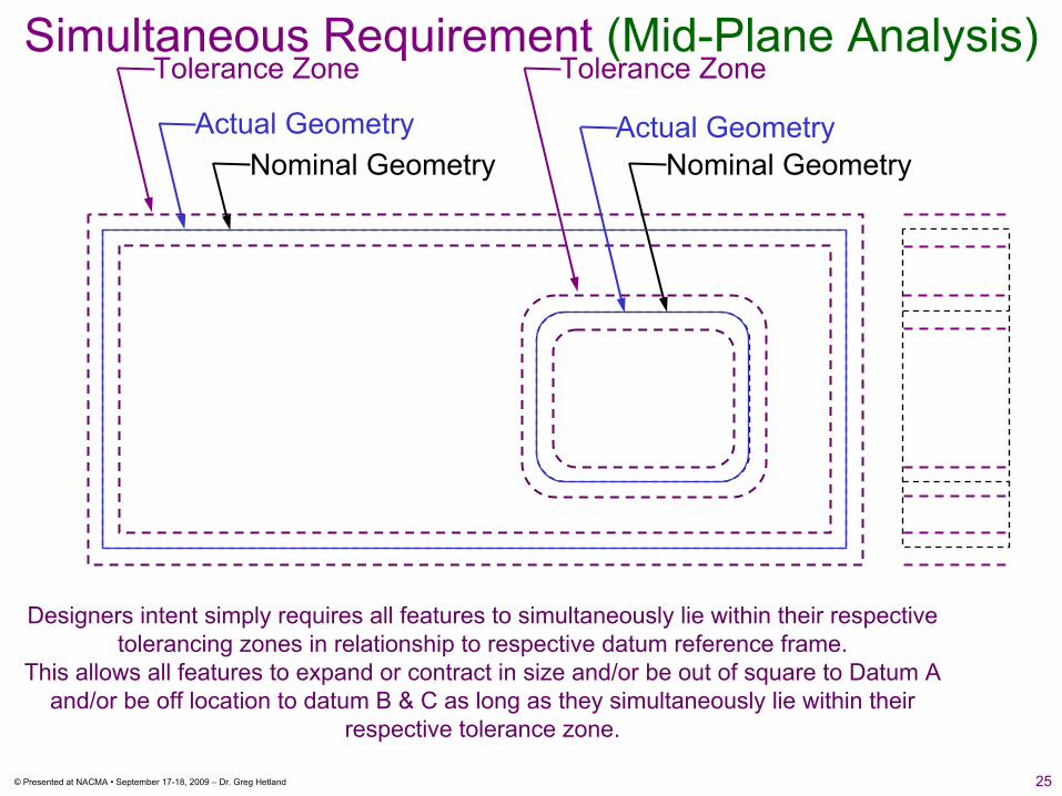
Nominal GeometryNominal Geometry
Tolerance Zone Tolerance Zone
Actual GeometryActual Geometry
Simultaneous Requirement (Mid-Plane Analysis)
Designers intent simply requires all features to simultaneously lie within their respective tolerancing zones in relationship to respective datum reference frame.
This allows all features to expand or contract in size and/or be out of square to Datum A and/or be off location to datum B & C as long as they simultaneously lie within their
respective tolerance zone.

26© Presented at NACMA • September 17-18, 2009 – Dr. Greg Hetland
Nominal GeometryNominal Geometry
Tolerance Zone Tolerance Zone
A
Actual GeometryActual Geometry
B
C
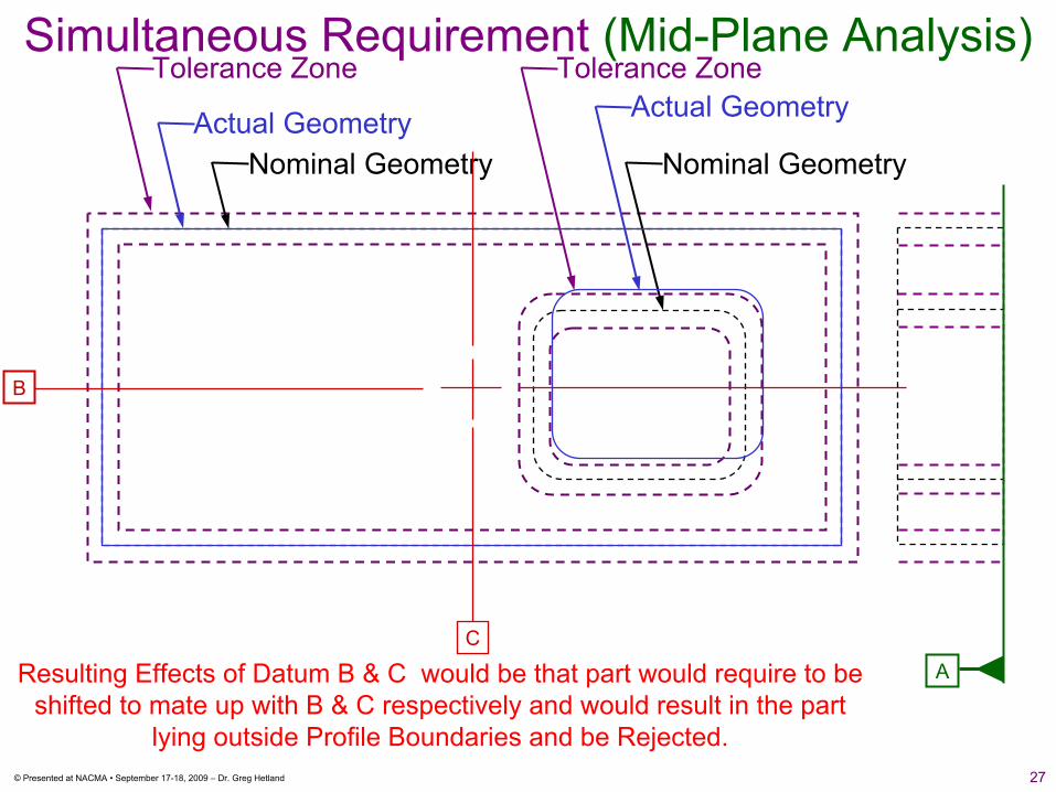
Simultaneous Requirement (Mid-Plane Analysis)
Problem: Without the part being constrained to datums B & C the part lies within its respective tolerance zones. Negative Effects of Datum B & C
would be that it would force the part to shift and potentially lie outside the respective Profile Boundaries
27© Presented at NACMA • September 17-18, 2009 – Dr. Greg Hetland
Nominal GeometryNominal Geometry
Tolerance Zone Tolerance Zone
A
Actual GeometryActual Geometry
B
C
Simultaneous Requirement (Mid-Plane Analysis)
Resulting Effects of Datum B & C would be that part would require to be shifted to mate up with B & C respectively and would result in the part
lying outside Profile Boundaries and be Rejected.
28© Presented at NACMA • September 17-18, 2009 – Dr. Greg Hetland
Unless Otherwise Specified All Dimensions Controlled by the CAD Model and are Basic
[Ö|).%|A]
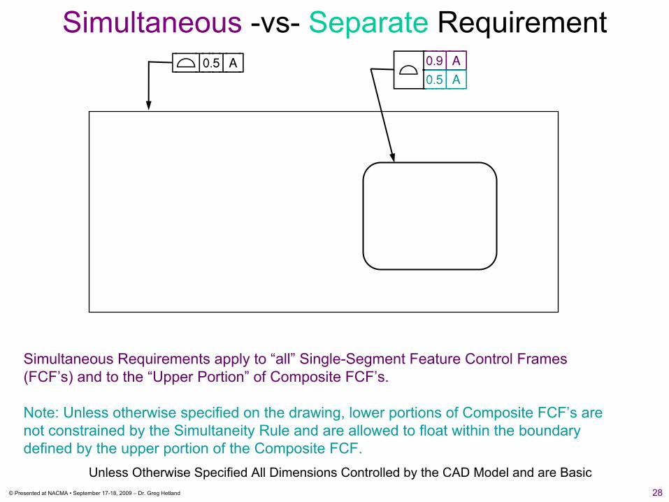
Simultaneous -vs- Separate Requirement
Simultaneous Requirements apply to “all” Single-Segment Feature Control Frames (FCF’s) and to the “Upper Portion” of Composite FCF’s.
Note: Unless otherwise specified on the drawing, lower portions of Composite FCF’s are not constrained by the Simultaneity Rule and are allowed to float within the boundary defined by the upper portion of the Composite FCF.
≈::).(|A]∆::).%|A]
29© Presented at NACMA • September 17-18, 2009 – Dr. Greg Hetland
[Ö|).%|A]
Unless Otherwise Specified All Dimensions Controlled by the CAD Model and are Basic
≈::).(|A]∆::).%|A]
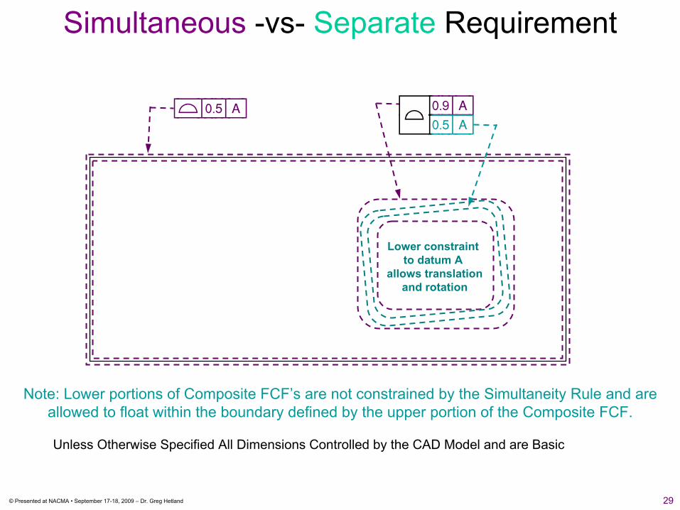
Lower constraint to datum A
allows translationand rotation
Note: Lower portions of Composite FCF’s are not constrained by the Simultaneity Rule and are allowed to float within the boundary defined by the upper portion of the Composite FCF.
Simultaneous -vs- Separate Requirement
30© Presented at NACMA • September 17-18, 2009 – Dr. Greg Hetland
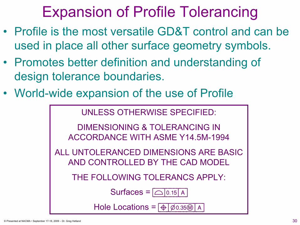
UNLESS OTHERWISE SPECIFIED:
DIMENSIONING & TOLERANCING IN ACCORDANCE WITH ASME Y14.5M-1994
ALL UNTOLERANCED DIMENSIONS ARE BASIC AND CONTROLLED BY THE CAD MODEL
THE FOLLOWING TOLERANCS APPLY:
Surfaces = [Ö|).!%|A]
Hole Locations = [ä|?),#%é|A]
Expansion of Profile Tolerancing• Profile is the most versatile GD&T control and can be
used in place all other surface geometry symbols.• Promotes better definition and understanding of
design tolerance boundaries.• World-wide expansion of the use of Profile
31© Presented at NACMA • September 17-18, 2009 – Dr. Greg Hetland
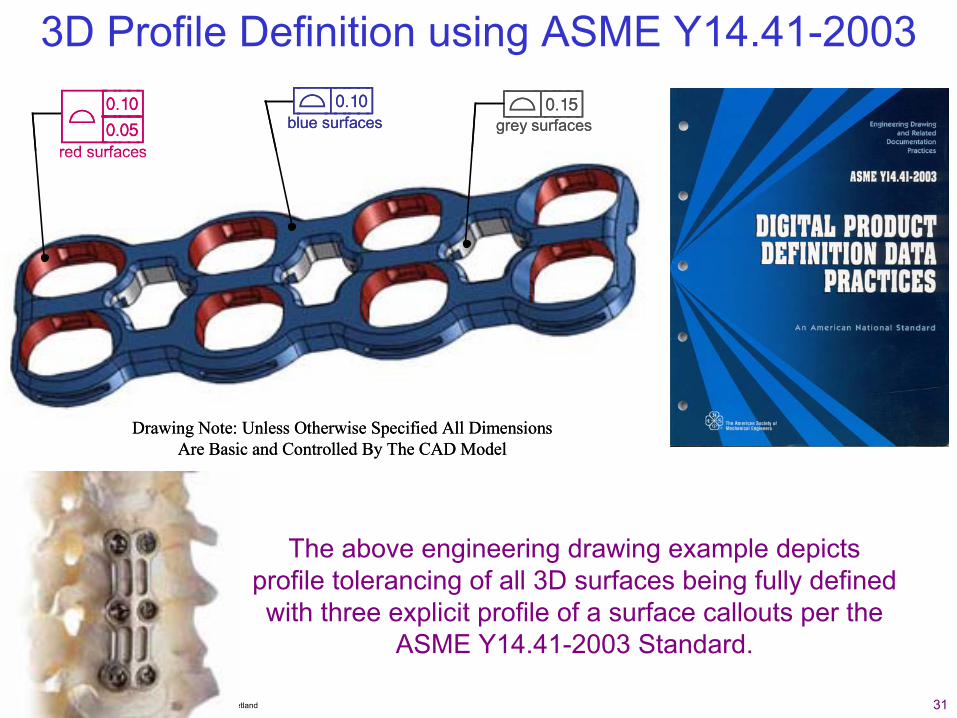
3D Profile Definition using ASME Y14.41-2003
The above engineering drawing example depicts profile tolerancing of all 3D surfaces being fully defined with three explicit profile of a surface callouts per the
ASME Y14.41-2003 Standard.
≈::).!)]∆::).)%]
[Ö|).!%][Ö|).!)]
red surfaces
blue surfaces grey surfaces
Drawing Note: Unless Otherwise Specified All Dimensions Are Basic and Controlled By The CAD Model
≈::).!)]∆::).)%]
[Ö|).!%][Ö|).!)]
red surfaces
blue surfaces grey surfaces
Drawing Note: Unless Otherwise Specified All Dimensions Are Basic and Controlled By The CAD Model
32© Presented at NACMA • September 17-18, 2009 – Dr. Greg Hetland
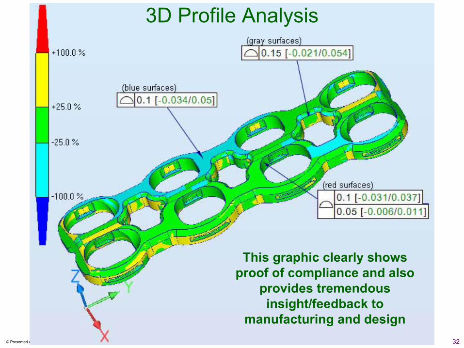
3D Profile Analysis
This graphic clearly shows proof of compliance and also
provides tremendous insight/feedback to
manufacturing and design

33© Presented at NACMA • September 17-18, 2009 – Dr. Greg Hetland
International Institute of GD&TInternational Institute of GD&T
g{tÇ~ çÉâ4
IIGDT