Embed Size (px)
Citation preview

Implementing Opportunistic RoutingAlgorithms in OMNeT++ 4.1
Bachelorarbeit
der Philosophisch-naturwissenschaftlichen Fakultat der
Universitat Bern
vorgelegt von
Bjorn MoslerFebruar 2012
Leiter der Arbeit:Professor Dr. Torsten Braun
Institut fur Informatik und angewandte Mathematik

Contents
Contents i
List of Figures iii
List of Tables iii
1 Introduction 1
1.1 Background . . . . . . . . . . . . . . . . . . . . . . . . . . . . . . . . . . . . . . . 1
1.1.1 Mobile Ad Hoc Networks . . . . . . . . . . . . . . . . . . . . . . . . . . . 1
1.1.2 MANET routing protocols . . . . . . . . . . . . . . . . . . . . . . . . . . . 1
1.1.3 Opportunistic routing . . . . . . . . . . . . . . . . . . . . . . . . . . . . . 2
1.2 Task/Problem Formulation . . . . . . . . . . . . . . . . . . . . . . . . . . . . . . 3
1.3 Motivation . . . . . . . . . . . . . . . . . . . . . . . . . . . . . . . . . . . . . . . 3
1.4 Contribution . . . . . . . . . . . . . . . . . . . . . . . . . . . . . . . . . . . . . . 3
1.5 Outline . . . . . . . . . . . . . . . . . . . . . . . . . . . . . . . . . . . . . . . . . 3
2 Related Work 5
2.1 OMNet++ Simulator . . . . . . . . . . . . . . . . . . . . . . . . . . . . . . . . . . 5
2.2 INETMANET . . . . . . . . . . . . . . . . . . . . . . . . . . . . . . . . . . . . . 5
2.3 Opponet . . . . . . . . . . . . . . . . . . . . . . . . . . . . . . . . . . . . . . . . . 5
2.4 OR framework . . . . . . . . . . . . . . . . . . . . . . . . . . . . . . . . . . . . . 6
2.5 ETX . . . . . . . . . . . . . . . . . . . . . . . . . . . . . . . . . . . . . . . . . . . 6
3 Opportunistic routing protocols 7
3.1 MORE . . . . . . . . . . . . . . . . . . . . . . . . . . . . . . . . . . . . . . . . . . 7
3.1.1 Terminology . . . . . . . . . . . . . . . . . . . . . . . . . . . . . . . . . . 7
3.1.2 Node roles . . . . . . . . . . . . . . . . . . . . . . . . . . . . . . . . . . . . 7
3.1.3 Network coding . . . . . . . . . . . . . . . . . . . . . . . . . . . . . . . . . 8
3.1.4 Forwarder list . . . . . . . . . . . . . . . . . . . . . . . . . . . . . . . . . . 8
3.1.5 Traffic control . . . . . . . . . . . . . . . . . . . . . . . . . . . . . . . . . . 8
3.2 ExOR . . . . . . . . . . . . . . . . . . . . . . . . . . . . . . . . . . . . . . . . . . 9
3.2.1 Terminology . . . . . . . . . . . . . . . . . . . . . . . . . . . . . . . . . . 9
3.2.2 Batch map . . . . . . . . . . . . . . . . . . . . . . . . . . . . . . . . . . . 9
3.2.3 Medium access . . . . . . . . . . . . . . . . . . . . . . . . . . . . . . . . . 11
i
4 Design and Implementation 134.1 OR Framework . . . . . . . . . . . . . . . . . . . . . . . . . . . . . . . . . . . . . 13
4.1.1 Neighbor management . . . . . . . . . . . . . . . . . . . . . . . . . . . . . 134.1.2 Network metrics . . . . . . . . . . . . . . . . . . . . . . . . . . . . . . . . 134.1.3 ETX reader . . . . . . . . . . . . . . . . . . . . . . . . . . . . . . . . . . . 144.1.4 Problems . . . . . . . . . . . . . . . . . . . . . . . . . . . . . . . . . . . . 14
4.2 MORE . . . . . . . . . . . . . . . . . . . . . . . . . . . . . . . . . . . . . . . . . . 144.2.1 Basics . . . . . . . . . . . . . . . . . . . . . . . . . . . . . . . . . . . . . . 144.2.2 Network coding . . . . . . . . . . . . . . . . . . . . . . . . . . . . . . . . . 174.2.3 Packet buffer . . . . . . . . . . . . . . . . . . . . . . . . . . . . . . . . . . 184.2.4 Batch transmission . . . . . . . . . . . . . . . . . . . . . . . . . . . . . . . 214.2.5 Matrix and Vector . . . . . . . . . . . . . . . . . . . . . . . . . . . . . . . 21
4.3 ExOR . . . . . . . . . . . . . . . . . . . . . . . . . . . . . . . . . . . . . . . . . . 214.3.1 Basics . . . . . . . . . . . . . . . . . . . . . . . . . . . . . . . . . . . . . . 214.3.2 PacketBuffer . . . . . . . . . . . . . . . . . . . . . . . . . . . . . . . . . . 26
5 Simulation and Evaluation 295.1 Simulation Setup . . . . . . . . . . . . . . . . . . . . . . . . . . . . . . . . . . . . 295.2 Metric & Results . . . . . . . . . . . . . . . . . . . . . . . . . . . . . . . . . . . . 29
5.2.1 Metrics . . . . . . . . . . . . . . . . . . . . . . . . . . . . . . . . . . . . . 295.2.2 Results . . . . . . . . . . . . . . . . . . . . . . . . . . . . . . . . . . . . . 30
6 Conclusion 416.1 Summary & Conclusion . . . . . . . . . . . . . . . . . . . . . . . . . . . . . . . . 416.2 Future work . . . . . . . . . . . . . . . . . . . . . . . . . . . . . . . . . . . . . . . 41
Bibliography 43
ii
Abstract
The primary challenge in building a MANET is equipping each device to continuously maintainthe information required to properly route traffic. MANET routing protocols are traditionallyusing a fixed route and a pre-defined next-hop. Opportunistic routing offers a new approachby neither enforcing a fixed route nor a particular next hop. Instead, the routing decision isdelegated to the receivers.
In this thesis we implement two opportunistic routing protocols MORE and ExOR. MORErandomly mixes packets before forwarding them. This randomness ensures that routers thathear the same transmission do not forward the same packets. Thus, MORE needs no specialscheduler to coordinate routers and can run directly on top of 802.11.
In ExOR the source node includes a list of candidate forwarders in each packet, prioritizedby closeness to the destination. The highest priority forwarder then broadcasts the packets inits buffer and remaining forwarders then transmit in order, sending only packets which were notacknowledged by higher priority nodes. The forwarders continue to cycle through the prioritylist until the destination has received enough packets.
We then evaluate MORE, ExOR and OLSR and compare their performance based on through-put, round-trip and transmission delay. Finally we discuss the results and try to give an expla-nation as to why the results are not as expected.

List of Figures
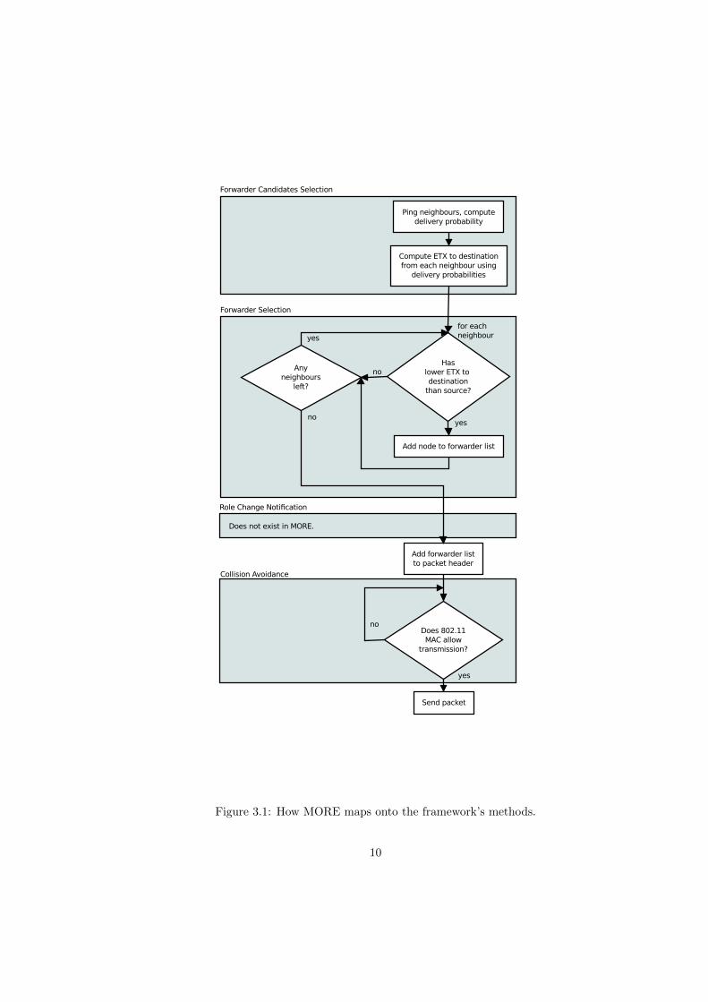
3.1 How MORE maps onto the framework’s methods. . . . . . . . . . . . . . . . . . 10
3.2 How the batch map is updated. . . . . . . . . . . . . . . . . . . . . . . . . . . . . 11
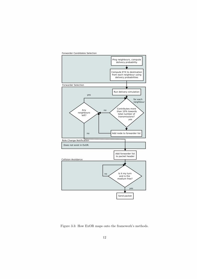
3.3 How ExOR maps onto the framework’s methods. . . . . . . . . . . . . . . . . . . 12
5.1 Simulation network topology . . . . . . . . . . . . . . . . . . . . . . . . . . . . . 30
5.2 Plot transmission delay batch size 16 . . . . . . . . . . . . . . . . . . . . . . . . . 32
5.3 Plot transmission delay batch size 32 . . . . . . . . . . . . . . . . . . . . . . . . . 33
5.4 Plot round-trip delay batch size 16 . . . . . . . . . . . . . . . . . . . . . . . . . . 34
5.5 Plot round-trip delay batch size 32 . . . . . . . . . . . . . . . . . . . . . . . . . . 35
5.6 Throughput plot batch size 16 . . . . . . . . . . . . . . . . . . . . . . . . . . . . 36
5.7 Throughput plot batch size 32 . . . . . . . . . . . . . . . . . . . . . . . . . . . . 37
5.8 Collisions plot MORE . . . . . . . . . . . . . . . . . . . . . . . . . . . . . . . . . 38
5.9 Collisions plot ExOR . . . . . . . . . . . . . . . . . . . . . . . . . . . . . . . . . . 39
List of Tables
3.1 MORE terminology . . . . . . . . . . . . . . . . . . . . . . . . . . . . . . . . . . . 7
3.2 ExOR terminology . . . . . . . . . . . . . . . . . . . . . . . . . . . . . . . . . . . 9
5.1 Simulation parameters . . . . . . . . . . . . . . . . . . . . . . . . . . . . . . . . . 29
iii
Listings
4.1 How nodes are represented within the framework . . . . . . . . . . . . . . . . . . 134.2 Snippet of MORE.h . . . . . . . . . . . . . . . . . . . . . . . . . . . . . . . . . . 154.3 How coded packets are handled by MORE . . . . . . . . . . . . . . . . . . . . . . 154.4 Decide whether to store or discard a packet . . . . . . . . . . . . . . . . . . . . . 184.5 Decode payload . . . . . . . . . . . . . . . . . . . . . . . . . . . . . . . . . . . . . 194.6 Add newly received packet to pre-encoded packet . . . . . . . . . . . . . . . . . . 204.7 Snippet of ExOR.h . . . . . . . . . . . . . . . . . . . . . . . . . . . . . . . . . . . 224.8 Forwarding fragment . . . . . . . . . . . . . . . . . . . . . . . . . . . . . . . . . . 224.9 How received packets are handled by ExOR . . . . . . . . . . . . . . . . . . . . . 234.10 Estimate data rate . . . . . . . . . . . . . . . . . . . . . . . . . . . . . . . . . . . 244.11 Estimate when to forward fragment . . . . . . . . . . . . . . . . . . . . . . . . . . 254.12 Update batch map and compute fragment size . . . . . . . . . . . . . . . . . . . 26
iv
Chapter 1
Introduction
1.1 Background
1.1.1 Mobile Ad Hoc Networks
A mobile ad-hoc network (MANET) is a self-configuring infrastructure-less network of mobiledevices connected by wireless links. The moving devices have the possibility to connect over awireless medium and form an arbitrary and dynamic network with wireless links. Each devicein a MANET is free to move independently in any direction, and will therefore change its linksto other devices frequently. This means that links between the nodes can change during time,new nodes can join/leave the network. A MANET is expected to be of larger size than the radiorange of the wireless antennas, because of this fact it could be necessary to route the trafficthrough a multi-hop path to give two nodes the ability to communicate. The primary challengein building a MANET is equipping each device to continuously maintain the information requiredto properly route traffic. Such networks may operate by themselves or may be connected to thelarger Internet1.
1.1.2 MANET routing protocols
Routing is one of the most important issues for MANETs. Routing protocols for MANETs canbe divided into proactive and reactive routing protocols.
Proactive routing
This type of protocols maintains fresh lists of destinations and their routes by periodically dis-tributing routing tables throughout the network. The main disadvantages of such algorithmsare high overhead because of constant route maintenance and slow reaction on restructuring andfailures. On the other hand there is little delay when sending a packet.
Reactive routing
This type of protocols finds a route on demand by flooding the network with Route Requestpackets. The main disadvantages of such algorithms are a high latency time in route findingand possible network clogging due to excessive flooding. On the other hand there is no constantmaintenance traffic.
1http://en.wikipedia.org/wiki/Mobile_ad_hoc_network
1
1.1.3 Opportunistic routing
Opportunistic routing protocols are a rather recently devised class of routing protocols for wire-less multi-hop networks. What separates opportunistic routing protocols from fixed-route routingprotocols is the fact that a packet’s route is not pre-determined by its source before the packettransmission. Because of its broadcast nature, a wireless transmission’s recipients are not neces-sarily known at the moment of transmission. This is due to the ever-changing physical conditionsand in some cases also changes in the network’s topology. Enforcing a pre-determined, possiblyoptimal route might produce the following outcomes:
(a) The transmission succeeds and the chosen route is still the optimal route.
(b) The transmission succeeds but some of the conditions have changed such that there is nowa shorter route or that the transmission reached further than expected. Both result inunnecessary hops in order to reach the destination.
(c) The network topology or the physical conditions have changed in such a way that the chosenroute is rendered invalid, necessitating a re-transmission.
Since power consumption is usually a concern in mobile and sensors networks, cases (b) and(c) are to be avoided. Opportunistic routing protocols leave it to a transmission’s recipients todecide on who will be the forwarder of the received packets. This scheme has two advantages:
(a) The decision on who is going to be the next hop is made using the latest possible information.
(b) The sender does not have to make — possibly faulty — assumptions on radio range andother physical conditions, thereby maximizing the progress made towards the destination.
But there are also some disadvantages. For instance the protocols have to make sure that no twonodes might forward the same packet at the same time. As of now there have been two ways ofdealing with that:
(a) Strict coordination of medium access: At any given time, only one node in the entire networkmay transmit. The first node to transmit would ideally be the one that is closest to thedestination. The other nodes listen to what is transmitted, so that they can discard alreadysent packets. This is roughly the approach taken by ExOR.
(b) Mixing packets via network coding: Upon receiving a new packet a node “mixes”2 it withalready received packets and then transmits the mixed packet. Depending on the mixingprocedure, duplicate transmissions by independent nodes are unlikely. This is roughly theapproach taken by MORE.
MORE
MORE [3] is a MAC-independent opportunistic routing protocol. MORE randomly mixes packetsbefore forwarding them. This randomness ensures that routers that hear the same transmissiondo not forward the same packets. Thus, MORE needs no special scheduler to coordinate routersand can run directly on top of 802.11.
2Using XOR, linear combinations etc.
2
ExOR
ExOR [2] is an integrated routing and MAC protocol for bulk transfers in multi-hop wirelessnetworks. ExOR exploits the broadcast nature of radios by making forwarding decisions basedon which nodes receive each transmission. The spatial diversity among receivers provides eachtransmission multiple opportunities to make progress in the face of packet losses. As a resultExOR can use long links with high loss rates, which would be avoided by unicast routing.
ExOR operates on batches of packets. The source node includes a list of candidate forwardersin each packet, prioritized by closeness to the destination. Receiving nodes buffer successfullyreceived packets and await the end of the batch. The highest priority forwarder then broadcaststhe packets in its buffer, including its copy of the “batch map” in each packet. The batch mapcontains the sender’s best guess of the highest priority node to have received each packet. Theremaining forwarders then transmit in order, sending only packets which were not acknowledgedin the batch maps of higher priority nodes. The forwarders continue to cycle through the prioritylist until the destination has enough packets to recover the original data using forward errorcorrection.
1.2 Task/Problem Formulation
The main goal of this thesis is to implement the MORE and ExOR protocol in OMNeT++ usingthe OR framework [4]. In a next step we compare them with OLSR3.
1.3 Motivation
There already are simulator-based implementations of opportunistic routings protocols, in par-ticular for ONE. [5] Unfortunately ONE employs an idealized and static model of the physicallayer. This makes it unsuitable for meaningful evaluations in wireless networks, where physicalconditions are subject to constant change. [4, p. 1]
OMNeT++ [6] combination with the INETMANET framework (see section 2.2) take intoaccount the dynamic conditions in wireless networks and are therefore better suited for evaluatingopportunistic routing protocols.
1.4 Contribution
The contributions of this thesis are some extensions to the OR framework [4] (see section 4.1),and implementations of MORE and ExOR in OMNeT++ 4.1.
1.5 Outline
In chapter 2, we look at projects that are related to or used in this thesis. Chapter 3 delivers moreconceptual details about MORE and ExOR, while chapter 4 expands on the details regarding thetwo protocol’s implementation. Chapter 5 is about evaluating MORE’s and ExOR’s performanceand how they compare to OLSR. Finally a conclusion is reached in chapter 6.
3http://tools.ietf.org/html/rfc3626
3

Chapter 2
Related Work
2.1 OMNet++ Simulator
OMNeT++ is an extensible, modular, component-based C++ simulation library and framework,primarily for building network simulators. ”Network” is meant in a broader sense that includeswired and wireless communication networks, on-chip networks, queueing networks, and so on.Domain-specific functionality such as support for sensor networks, wireless ad-hoc networks,Internet protocols, performance modeling, photonic networks, etc, is provided by model frame-works, developed as independent projects. OMNeT++ offers an Eclipse-based IDE, a graphicalruntime environment, and a host of other tools. There are extensions for real-time simulation,network emulation, alternative programming languages (Java, C#), database integration, Sys-temC integration, and several other functions. 1
2.2 INETMANET
INETMANET is based on INET Framework2 and continuously being developed. Generally itprovides the same functionality as the INET Framework, but contains additional protocols andcomponents that are especially useful while modeling wireless communication like propagationmodels, link layer and routing protocols and mobility models.3
2.3 Opponet
The Opponet framework offers mechanisms for simulating opportunistic and delay-tolerant net-works in the OMNeT++ discrete event simulator. The mechanisms allow for simulating opensystems of wireless mobile nodes where mobility or contact traces are used to drive the simula-tions. This way mobility generation is separated from the core OMNeT++ protocol simulationswhich facilitates importing synthetic or real data from external mobility generators, real mobilitytracking data or real contact traces. [7]
1Verbatim from http://omnetpp.org/, 10.08.20112http://inet.omnetpp.org/3INETMANET README on https://github.com/inetmanet/inetmanet/blob/master/README.
INETMANET, 18.01.2012
5
2.4 OR framework
A framework [4], which is based on the Opponet project (see section 2.3), has been developed bythe CDS research group at the University of Bern for simulating opportunistic routing protocolsin OMNeT++. It provides common functionality like ETX computation, neighbour managementetc as well as an abstract protocol base class which allows for easy implementation of furtheropportunistic routing protocols.
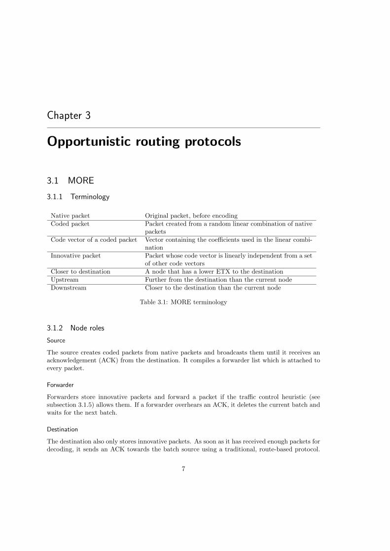
The class hierarchy is built on the assumption that all opportunistic routing protocols sharefunctionality and that the way they work can roughly be split up into four steps. In order toimplement a new protocol, one needs to subclass the abstract base class and implement thefour virtual functions, which correspond to the four common steps in opportunistic routingprotocols. [4] Those four steps are:
Forwarder Candidates Selection Build a set of potential forwarders.
Forwarder Selection Determine the forwarder.
Forwarder Role Change Notification Notify other nodes about who will be forwarding thepacket.
Collision Avoidance Make sure that no two nodes transmit at the same time.
See Figure 3.3 and Figure 3.1 for how ExOR and MORE map onto those four steps.
2.5 ETX
The expected transmission count metric (ETX) [8] of a link is calculated using the forward andreverse delivery ratios (FDR and RDR resp.) of the link. The forward delivery ratio, df , isthe measured probability that a data packet successfully arrives at the recipient. The reversedelivery ratio, dr, is the probability that the ACK packet is successfully received. These deliveryratios can be measured by sending ping probes. The expected probability that a transmissionis successfully received and acknowledged is df · dr. A sender will retransmit a packet that isnot successfully acknowledged. Because each attempt to transmit a packet can be considered aBernoulli trial, the expected number of transmissions is:
ETX =1
df · dr
6
Chapter 3
Opportunistic routing protocols
3.1 MORE
3.1.1 Terminology
Native packet Original packet, before encodingCoded packet Packet created from a random linear combination of native
packetsCode vector of a coded packet Vector containing the coefficients used in the linear combi-
nationInnovative packet Packet whose code vector is linearly independent from a set
of other code vectorsCloser to destination A node that has a lower ETX to the destinationUpstream Further from the destination than the current nodeDownstream Closer to the destination than the current node
Table 3.1: MORE terminology
3.1.2 Node roles
Source
The source creates coded packets from native packets and broadcasts them until it receives anacknowledgement (ACK) from the destination. It compiles a forwarder list which is attached toevery packet.
Forwarder
Forwarders store innovative packets and forward a packet if the traffic control heuristic (seesubsection 3.1.5) allows them. If a forwarder overhears an ACK, it deletes the current batch andwaits for the next batch.
Destination
The destination also only stores innovative packets. As soon as it has received enough packets fordecoding, it sends an ACK towards the batch source using a traditional, route-based protocol.
7
It then decodes the batch, processes the native packets and finally deletes all data associatedwith the batch.
3.1.3 Network coding
MORE combines packets by creating a per-byte linear combination of the native packets’ payload.At the source n native packets are combined into a single packet by generating a random
vector c of size n and then computing the following sum for each byte:
vi = c0 · b0i + . . .+ cn · bni
where bki is the i-th byte of the k-th native packet’s payload and vi is the coded packet’s i-thbyte. The destination can recover the original payload if it has received n innovative packets. Atthat point the destination has n equations (the code vectors) to solve for n variables (the originaldata bytes). So the decoding boils down to solving a system of n linear equations. There aremultiple ways to do this, two of them will be discussed in subsection 4.2.3
Furthermore packets are recombined at each forwarder. Each forwarder has to keep ready apre-encoded packet for transmission. If the forwarder has only received one packet so far, the pre-encoded packet is just that packet. Otherwise the two packets are combined by multiplying boththe newly arrived packet’s code vector and each individual payload byte by the same randomnumber and adding it to the pre-encoded packet. It is easy to show that the so constructedpacket p still constitutes a linear combination of the native packets:
p′ = c · pnew + ppre
p′ = ca0 · p0 + . . .+ can · pn +m0 · p0 + . . .+mn · pnp′ = (ca0 +m0)p0 + . . .+ (can +mn)pn
In the above equations, pi are the native packets, a is pnew’s code vector and m is ppre’s codevector.
3.1.4 Forwarder list
MORE employs the ETX metric as a measure of distance between nodes. The forwarder listcontains all nodes that have a lower ETX to the destination than the source. It is sorted byETX to the destination in ascending order and stays the same during the batch’s lifetime.
3.1.5 Traffic control
In order to keep nodes from transmitting all the time and thus occupying the medium, MOREemploys a traffic control heuristic that is based on delivery probabilities.
The heuristic is computed using three formulas. In the following equations, i > j denotesthat node i is closer to the destination than node j, εij denotes the loss probability from nodei to j and zi is the expected number of transmissions that forwarder i must make to route onepacket from the source to the destination. The first formula computes Lj , the number of packetsthat node j must forward. It computes for each node i the number of packets j received from i,taking into account the probability that that particular packet is not heard by any other nodedownstream from j.
Lj =∑i>j
(zi(1− εij)∏k<j
εik)
8
The next equation describes how zj is computed:
zj =Lj
1−∏
k<j εjk
The denominator describes the probability that some node downstream from j receives thepacket. In the implementation, the zi values are computed at each node using an incrementalalgorithm, which is also described in [3]. Finally, the node computes its tx credit, that is,the number of transmissions that a node should make for every packet it receives from a nodeupstream:
tx crediti =zi∑
j>i zj(1− εji)
The actual traffic control works as follows: Every node keeps a credit counter variable. If aforwarder receives an innovative packet from a node upstream, it increases its credit counterby the corresponding tx credit. If the credit counter is positive, the forwarder transmitsa coded packet and then decrements its credit counter. Otherwise it does not transmit atall. For a more detailed description refer to [3, p. 26-28].
3.2 ExOR
3.2.1 Terminology
Fragment The set of packets a node forwards, i.e. the set of packetsnot yet received by higher priority nodes
Batch map An array indexed by the packet number which contains thehighest priority node’s priority known to have received thepacket designated by the index
Forwarder id A node’s position in the forwarder list (starts at zero)Node priority A node’s forwarder id + 1 (source is not included in for-
warder list)Null-Packet A packet only containing a batch map and no payload
Table 3.2: ExOR terminology
3.2.2 Batch map
The batch map plays a central role in ExOR. First of all a node uses it as an acknowledgementmechanism, that is, to find out, which packets it has yet to forward. This is easily achieved bypicking the packets whose entry in the batch map is smaller than the current node’s priority.
On the other hand the number of packets to forward — the fragment size — is used toschedule medium access (see subsection 3.2.3).
Example
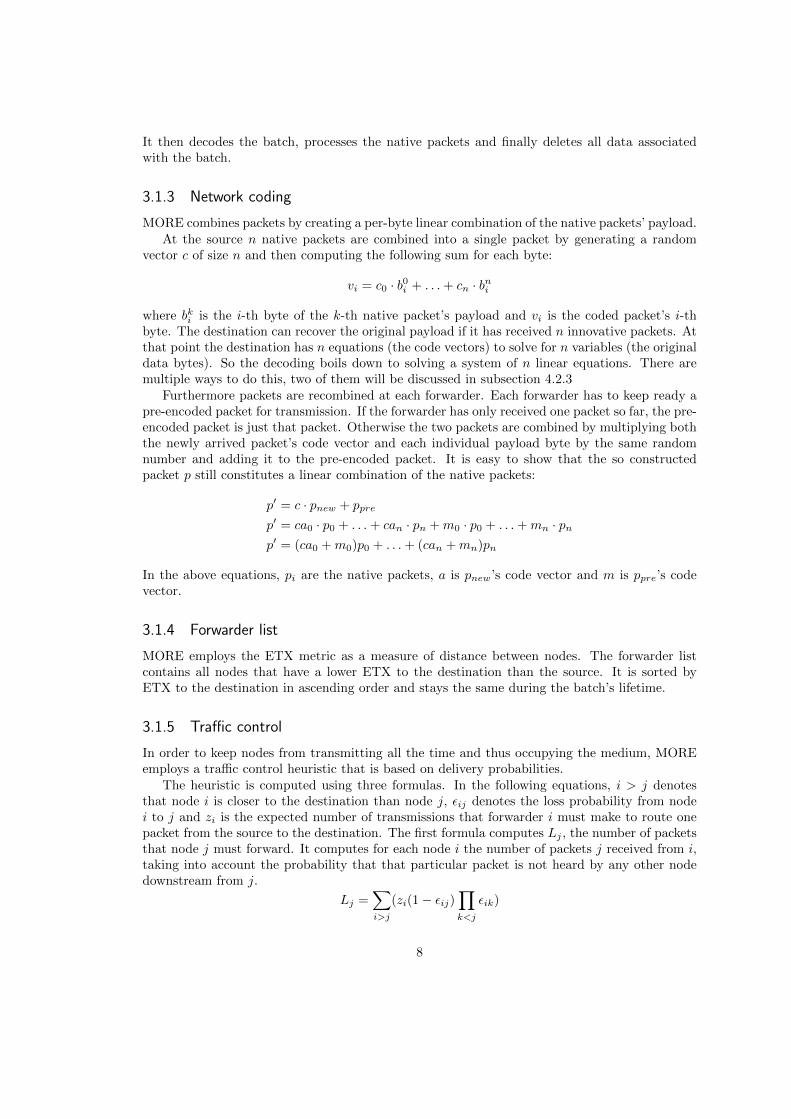
Figure 3.2 graphically describes a batch map update, highlighting indirect updates due to gos-siping. The received map shown on the right is received in a packet from forwarder 3, and differsin 13 locations which are highlighted in shades of gray. For ten of the entries, which are shown indark gray, the map is updated to show forwarder 4 as the highest priority forwarder responsible
9
Does not exist in MORE.
Forwarder Candidates Selection
Ping neighbours, computedelivery probability
Compute ETX to destinationfrom each neighbour using
delivery probabilities
Add node to forwarder list
Haslower ETX to destination
than source?
yes
Does 802.11MAC allow
transmission?
Add forwarder listto packet header
noAnyneighbours
left?
yes
Send packet
no
yes
no
Forwarder Selection
Collision Avoidance
Role Change Notification
for eachneighbour
Figure 3.1: How MORE maps onto the framework’s methods.
10
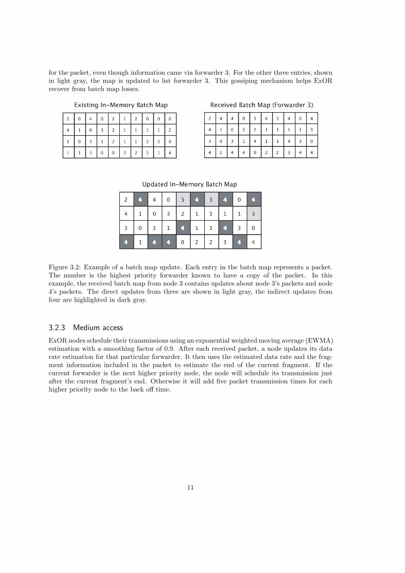
for the packet, even though information came via forwarder 3. For the other three entries, shownin light gray, the map is updated to list forwarder 3. This gossiping mechanism helps ExORrecover from batch map losses.
Figure 3.2: Example of a batch map update. Each entry in the batch map represents a packet.The number is the highest priority forwarder known to have a copy of the packet. In thisexample, the received batch map from node 3 contains updates about node 3’s packets and node4’s packets. The direct updates from three are shown in light gray, the indirect updates fromfour are highlighted in dark gray.
3.2.3 Medium access
ExOR nodes schedule their transmissions using an exponential weighted moving average (EWMA)estimation with a smoothing factor of 0.9. After each received packet, a node updates its datarate estimation for that particular forwarder. It then uses the estimated data rate and the frag-ment information included in the packet to estimate the end of the current fragment. If thecurrent forwarder is the next higher priority node, the node will schedule its transmission justafter the current fragment’s end. Otherwise it will add five packet transmission times for eachhigher priority node to the back off time.
11
Does not exist in ExOR.
Forwarder Candidates Selection
Ping neighbours, computedelivery probability
Compute ETX to destinationfrom each neighbour using
delivery probabilities
Add node to forwarder list
Contributes more than 10% towards
total number oftransmissions?
yes
Is it my turnand is the
medium free?
Add forwarder listto packet header
noAnyneighbours
left?
yes
Send packet
no
yes
no
Forwarder Selection
Collision Avoidance
Role Change Notification
for eachneighbour
Run delivery simulation
Figure 3.3: How ExOR maps onto the framework’s methods.
12
Chapter 4
Design and Implementation
4.1 OR Framework
Over the course of this project, several modifications to the current OR framework have beenmade. Some of them will be described in the following sub sections.
4.1.1 Neighbor management
Originally the network nodes in the framework were represented by a rather heavy-weight datastructure, which included a lot of internal information that are unnecessary for developing routingprotocols. In the case of MORE and ExOR, a node is represented by an IP address and itsETX, [8], forward and reverse delivery ratio with respect to current node.
Listing 4.1: How nodes are represented within the framework
1 struct Node {2 IPAddress address;34 double etx;5 double fdr;6 double rdr;78 double tx_credit; // MORE −s p e c i f i c9
10 [...]11 };
4.1.2 Network metrics
Both MORE and ExOR heavily rely on the ETX network metric. ExOR uses it to select andprioritize its forwarder set, which in turn determines how transmissions are scheduled. MOREuses it to select its forwarder set and to compute its traffic-control heuristic.
It is likely that future opportunistic routing protocols also rely on network metrics like ETX.Since a framework is supposed to relieve the protocol designer of burdens that are not protocol-specific, it makes sense to make network metrics a part the framework.
The base class ORBase includes a method double getMetric(Metric metric, IPAddress
ip) which is supposed to be called by the protocols. The first parameter specifies which metricshould be returned — at the moment only ETX is supported. The second parameter specifies the
13
node for which the metric should be returned with respect to the node which invokes the method.In the future, the framework should support the computation of a full weighted network graphusing shortest-path algorithms and make them available through the method double getMetric
(Metric metric, IPAddress source, IPAddress destination). This would be helpful asboth MORE and ExOR — and probably future protocols — rely on knowing the whole networkgraph.
4.1.3 ETX reader
INETMANET offers ways to compute ETX values during the simulation using ping probes.But sometimes it might be desirable to use static ETX values which stay the same for theduration of the simulation. For that purpose a helper class was implemented, which reads ETXvalues from a CSV file and makes them available through the framework methods discussed insubsection 4.1.2. Thus it is possible to switch between dynamic and static ETX values just bychanging the simulation configuration, but without changes to the source code.
The CSV file is assumed to have the following format: If there are n nodes in the network,then the file is supposed to have n lines. Each line (row) contains n comma-separated strings(columns). The row and column index then corresponds to the source’s and the destination’sIP’s host number respectively. For example: The ETX of 192.168.0.12 to 192.168.0.23 is in row12, column 23.
In order to support more than one metric per host-pair, each string can hold multiple space-separated numbers. The current implementation assumes that each string contains three valuesin this order: FDR, RDR, ETX. At the moment the reader only supports flat networks up to254 hosts.
4.1.4 Problems
Currently the protocols have too little control over the radio/MAC layer. MORE and ExORsolely rely on broadcast transmissions. But broadcast packets are not re-transmitted in case of acollision and generally not as reliable as unicast transmissions1. Furthermore the protocols neverlearn about a collision and so just have to assume that the transmission was successful. It is alsonot possible for a protocol to cancel a scheduled transmission. Some simulation results will begiven in subsection 5.2.2 to illustrate this problem.
4.2 MORE
4.2.1 Basics
The basic architecture is pre-defined by the OR-Framework, which means that there is a classMORE, which inherits from ORBase and is meant to contain most of the protocol’s logic. Addi-tionally there are a few helper classes for specialised tasks, in order to keep the main class asuncluttered as possible.
1IEEE Std 802.11TM-2007, section 9.2.7
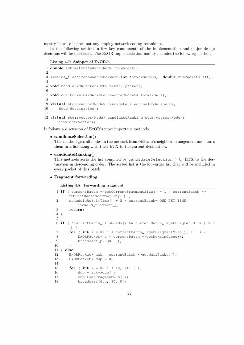
14
In the following sections a few key components of the implementation and major design decisionswill be discussed. The MORE implementation mainly includes the following methods:
Listing 4.2: Snippet of MORE.h
1 virtual std::vector<Node> candidateSelection(Node source, Node destination);
23 virtual Node forwarderSelection(std::vector<Node>& candidatesRanked);45 void handleCodedMessage(MorePacket* packet);67 void handleAckMessage(MorePacket* packet);89 void computeNeededTransmissions();
1011 void computeTxCredit(std::valarray<double>& z, const std::vector<Node>&
nodes, std::vector<Node>::const_iterator it);
We spend the rest of the section with a more detailed discussion of the above methods.
• candidateSelection()This method retrieves the list of nodes in the network from ORBase and store them togetherwith their ETX to the batch’s destination.
• candidateRanking()This method sorts the forwarder list by ETX to the destination in ascending order.
• handleCodedMessage()
Listing 4.3: How coded packets are handled by MORE
1 void MORE::handleCodedMessage(MorePacket* p) {2 CodedPacket* cp = check_and_cast<CodedPacket*>(p);34 i f ( (!cp->inForwarderList(ip_address_) && !(cp->getDst() ==
ip_address_)) || cp->getSrc() == ip_address_ ) {5 delete cp;6 return;7 }89 i f (packet_buffer_ == 0) {
10 i f ( cp->getBatch_id() <= last_batch_id_ ) {11 delete cp;12 return;13 }14 packet_buffer_ = new more::PacketBuffer(cp, gf_, ip_address_,
getNeighborEtx(cp->getDst()));1516 forwarders_ = cp->getForwarderList();17 batch_start_ = cp->getTimestamp();18 last_batch_id_ = cp->getBatch_id();1920 i f ( !IAmDestination() ) {21 computeNeededTransmissions();22 }
15
23 scheduleAt(simTime(), batch_timeout_check_);24 } else i f (cp->getBatch_id() > packet_buffer_->batch_id()) {25 dropBatch("out of date.");2627 packet_buffer_ = new more::PacketBuffer(cp, gf_, ip_address_,
getNeighborEtx(cp->getDst()));2829 i f ( !IAmDestination() ) {30 computeNeededTransmissions();31 }3233 last_batch_id_ = cp->getBatch_id();34 batch_start_ = cp->getTimestamp();35 }3637 i f ( cp->getForwarderEtx() >= getNeighborEtx(cp->getDst()) && !
IAmDestination() ) {38 credit_counter_ += cp->getForwarderTxCredit();39 }4041 bool was_innovative = packet_buffer_->addOrDiscard(cp);4243 i f (packet_buffer_->ready() && IAmDestination() ) {44 AckPacket* ack = new AckPacket("MORE ACK", more::ACK);45 // . . .4647 sendToIp(ack->dup(), packet_buffer_->source(), 30, 0,
IP_PROT_MANET);4849 uint8_t* payload = packet_buffer_->decode();5051 dropBatch("decoded.");5253 delete[] payload;54 delete packet_buffer_;55 packet_buffer_ = 0;56 } else i f ( credit_counter_ > 0 && !IAmDestination() &&
was_innovative) {57 broadcast(packet_buffer_->getPreEncodedPacket(), 30, par("
packetForwardDelay").doubleValue());58 credit_counter_--;59 packets_sent_++;60 }61 }
First the cases are covered when the node should ignore the packet (line 4–7), that is, whenthe receiver is neither in the forwarder list nor the destination, and also if it is the batch’ssource.
Then, if there is no current buffer, but the packet belongs to an outdated batch, the packetis ignored as well (line 10–12). Otherwise a new buffer is created and computations for thetraffic control heuristic are made (line 14–23).
If there is a current buffer, but its batch id is lower than the packet’s, the current buffer is
16
dropped and a new buffer is created.
In line 37–38 the node’s credit counter is updated depending on whether the packetwas sent by a node from up- or downstream. It follows the packet’s inspection by thepacket buffer in line 41, which will yield whether the packet is innovative or not.
Afterwards, if the packet buffer is ready for decoding and if the current node is also thedestination, it sends the ACK towards the batch’s destination, decodes and subsequentlydiscards the batch (line 43–55). Otherwise, given that its credit counter is positive, itis not the destination and that the received packet was innovative, the node transmits apacket (line 56–59).
• handleAckMessage()This method handles received ACKs. When a node receives an ACK which belongs to anoutdated batch, it will simply ignore it. If the ACK belongs to a currently active batch,the node will discard the current buffer. Finally if the ACK belongs to a batch of whichthe current node is the source, the node records its throughput and the round-trip timebefore stopping the simulation.
• computeNeededTransmissions() & computeTxCredit()In those two methods MORE’s traffic control heuristic is computed. The detailed formulasand algorithms are specified in [3, p. 26–29]. Although we implemented the algorithmsas specified, they did not perform very well. For instance, the algorithm computes thatthe source would have to do less than one transmission in order to get a packet to thedestination. As a consequence, the computed tx credit values are wrong as well andtherefore the traffic control is ineffective.
4.2.2 Network coding
Just as in [3], network coding related calculations are done over the Galois field GF (28)2. Itsarithmetic operations can be implemented in a computationally efficient fashion and its elementscan be expressed in one byte.
The class Gf256 offers methods for performing arithmetic operations in GF (28). In GF (28)subtraction and addition are both equivalent to the XOR operation, which is part of virtuallyevery CPU instruction set. Multiplication is more complex and there are multiple ways toimplement it. Here are the two most efficient:
1. Create two look-up tables {exp(a) : a ∈ GF (28)} and {log(a) : a ∈ GF (28)}. Because oflog(a · b) = log(a) + log(b), multiplication can be reduced to a · b = exp(log(a) + log(b)).The look-up tables require 2 · 256 = 512 bytes of memory.
2. Create a look-up table {a · b : (a, b) ∈ GF (28)×GF (28)} and design a hash function whichmaps every pair of elements in GF (28) to the corresponding result. This look-up tablerequires 256 · 256 = 65536 bytes.
Currently method 1 is implemented because it is a good compromise between memory usage andcomputational complexity.3
2A Galois field (GF) with an order of 28. It contains the elements 0 . . . 255.3There are algorithms which compute every result on the fly, but since they would be run (possibly tens of)
thousands of times, while just producing 255 different values, it would not be economical to use them.
17
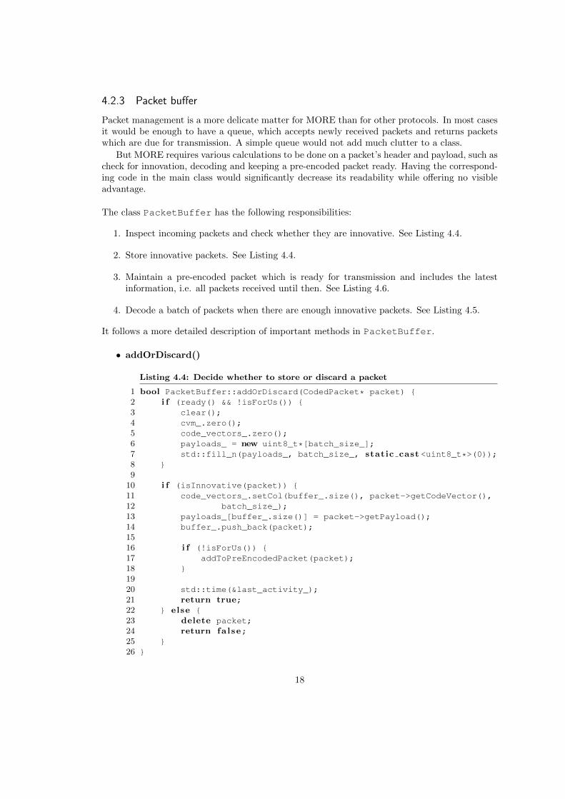
4.2.3 Packet buffer
Packet management is a more delicate matter for MORE than for other protocols. In most casesit would be enough to have a queue, which accepts newly received packets and returns packetswhich are due for transmission. A simple queue would not add much clutter to a class.
But MORE requires various calculations to be done on a packet’s header and payload, such ascheck for innovation, decoding and keeping a pre-encoded packet ready. Having the correspond-ing code in the main class would significantly decrease its readability while offering no visibleadvantage.
The class PacketBuffer has the following responsibilities:
1. Inspect incoming packets and check whether they are innovative. See Listing 4.4.
2. Store innovative packets. See Listing 4.4.
3. Maintain a pre-encoded packet which is ready for transmission and includes the latestinformation, i.e. all packets received until then. See Listing 4.6.
4. Decode a batch of packets when there are enough innovative packets. See Listing 4.5.
It follows a more detailed description of important methods in PacketBuffer.
• addOrDiscard()
Listing 4.4: Decide whether to store or discard a packet
1 bool PacketBuffer::addOrDiscard(CodedPacket* packet) {2 i f (ready() && !isForUs()) {3 clear();4 cvm_.zero();5 code_vectors_.zero();6 payloads_ = new uint8_t*[batch_size_];7 std::fill_n(payloads_, batch_size_, static cast <uint8_t*>(0));8 }9
10 i f (isInnovative(packet)) {11 code_vectors_.setCol(buffer_.size(), packet->getCodeVector(),12 batch_size_);13 payloads_[buffer_.size()] = packet->getPayload();14 buffer_.push_back(packet);1516 i f (!isForUs()) {17 addToPreEncodedPacket(packet);18 }1920 std::time(&last_activity_);21 return true;22 } else {23 delete packet;24 return false;25 }26 }
18
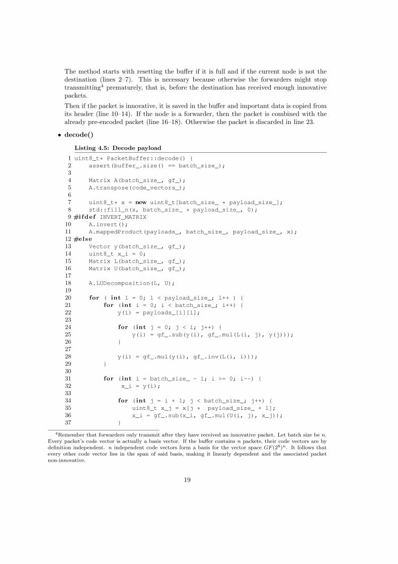
The method starts with resetting the buffer if it is full and if the current node is not thedestination (lines 2–7). This is necessary because otherwise the forwarders might stoptransmitting4 prematurely, that is, before the destination has received enough innovativepackets.
Then if the packet is innovative, it is saved in the buffer and important data is copied fromits header (line 10–14). If the node is a forwarder, then the packet is combined with thealready pre-encoded packet (line 16–18). Otherwise the packet is discarded in line 23.
• decode()
Listing 4.5: Decode payload
1 uint8_t* PacketBuffer::decode() {2 assert(buffer_.size() == batch_size_);34 Matrix A(batch_size_, gf_);5 A.transpose(code_vectors_);67 uint8_t* x = new uint8_t[batch_size_ * payload_size_];8 std::fill_n(x, batch_size_ * payload_size_, 0);9 #ifdef INVERT_MATRIX
10 A.invert();11 A.mappedProduct(payloads_, batch_size_, payload_size_, x);12 #else13 Vector y(batch_size_, gf_);14 uint8_t x_i = 0;15 Matrix L(batch_size_, gf_);16 Matrix U(batch_size_, gf_);1718 A.LUDecomposition(L, U);1920 for ( int l = 0; l < payload_size_; l++ ) {21 for (int i = 0; i < batch_size_; i++) {22 y(i) = payloads_[i][l];2324 for (int j = 0; j < i; j++) {25 y(i) = gf_.sub(y(i), gf_.mul(L(i, j), y(j)));26 }2728 y(i) = gf_.mul(y(i), gf_.inv(L(i, i)));29 }3031 for (int i = batch_size_ - 1; i >= 0; i--) {32 x_i = y(i);3334 for (int j = i + 1; j < batch_size_; j++) {35 uint8_t x_j = x[j * payload_size_ + l];36 x_i = gf_.sub(x_i, gf_.mul(U(i, j), x_j));37 }
4Remember that forwarders only transmit after they have received an innovative packet. Let batch size be n.Every packet’s code vector is actually a basis vector. If the buffer contains n packets, their code vectors are bydefinition independent. n independent code vectors form a basis for the vector space GF (28)n. It follows thatevery other code vector lies in the span of said basis, making it linearly dependent and the associated packetnon-innovative.
19
3839 uint8_t inv = gf_.inv(U(i,i));40 x_i = gf_.mul(x_i, inv);41 x[i * payload_size_ + l] = x_i;42 }43 y.zero();44 x_i = 0;45 }46 #endif47 return x;48 }
This is where the original payload is retrieved from the coded packets. As mentioned before,the code vectors form the coefficient matrix (denoted A in the listing) of a system of linearequations. So the system to solve is Ax = b, where x is the original payload and b is thecoded payload. In the above method, two ways of solving this system are implemented.
The first way (lines 11 and 12) consists of inverting the matrix and then retrieving theoriginal payload by repeatedly computing A−1b with an appropriate5 b.
The second way (line 14–49) uses LU-Decomposition6, which decomposes A into the lower-triangular matrix L and the upper-triangular matrix U with A = LU . Solving the systemAx = b can now be reduced to first solving Ly = b for y and then Ux = y for x. SinceL and U are both triangular, this can be quickly done by using forward (line 23–31) andbackward substitution (line 33–45) respectively. Similar to the first method, those twosubstitution steps need to be performed for all appropriate b, as explained in footnote 5.
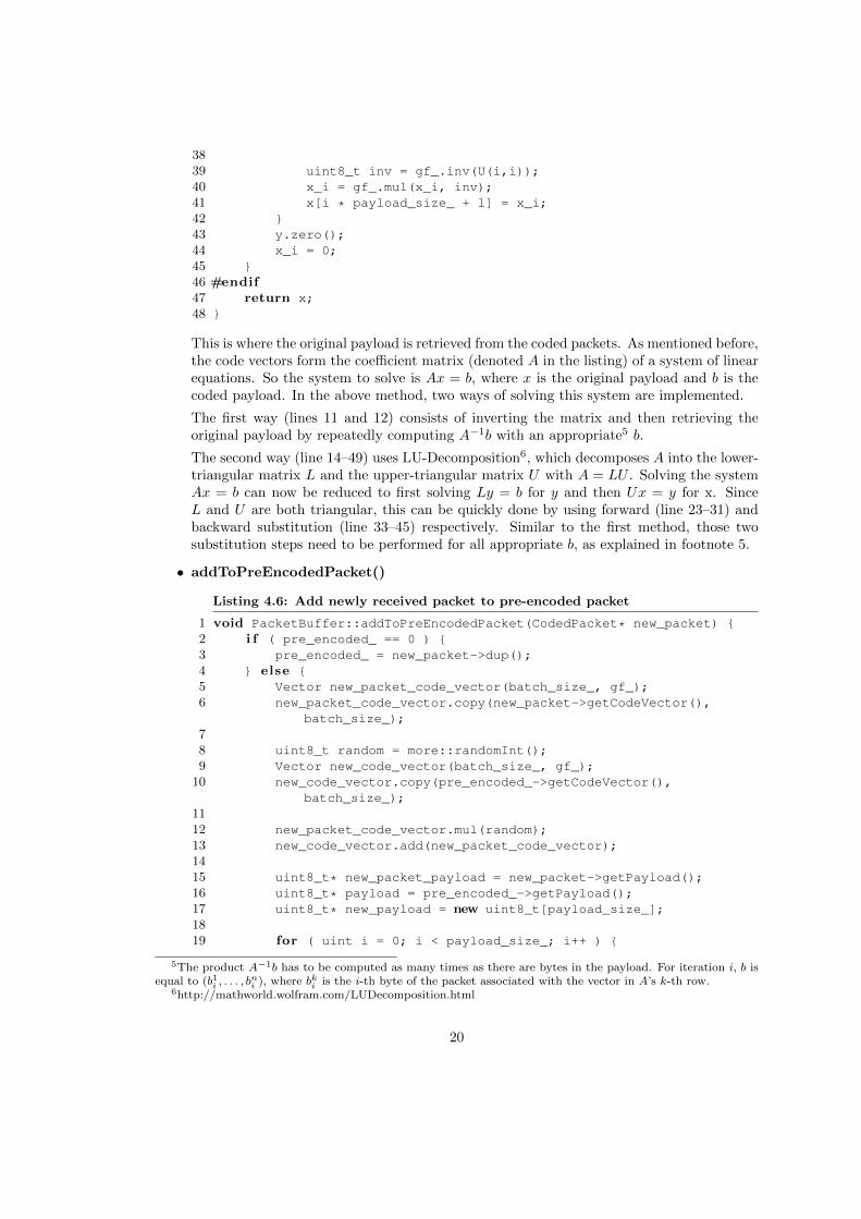
• addToPreEncodedPacket()
Listing 4.6: Add newly received packet to pre-encoded packet
1 void PacketBuffer::addToPreEncodedPacket(CodedPacket* new_packet) {2 i f ( pre_encoded_ == 0 ) {3 pre_encoded_ = new_packet->dup();4 } else {5 Vector new_packet_code_vector(batch_size_, gf_);6 new_packet_code_vector.copy(new_packet->getCodeVector(),
batch_size_);78 uint8_t random = more::randomInt();9 Vector new_code_vector(batch_size_, gf_);
10 new_code_vector.copy(pre_encoded_->getCodeVector(),batch_size_);
1112 new_packet_code_vector.mul(random);13 new_code_vector.add(new_packet_code_vector);1415 uint8_t* new_packet_payload = new_packet->getPayload();16 uint8_t* payload = pre_encoded_->getPayload();17 uint8_t* new_payload = new uint8_t[payload_size_];1819 for ( uint i = 0; i < payload_size_; i++ ) {
5The product A−1b has to be computed as many times as there are bytes in the payload. For iteration i, b isequal to (b1i , . . . , b
ni ), where bki is the i-th byte of the packet associated with the vector in A’s k-th row.
6http://mathworld.wolfram.com/LUDecomposition.html
20
20 new_payload[i] = gf_.add(payload[i], gf_.mul(random,new_packet_payload[i]));
21 }2223 delete pre_encoded_;24 pre_encoded_ = 0;2526 pre_encoded_ = new CodedPacket("CodedPacket (PB)", more::CODED
);27 // . . .28 // s e t v a r i a b l e s29 }30 }
If there is no pre-encoded packet, a duplicate of the newly received packet is used (line2–3). Then the new code vector vnew is computed in line 8–13. Let r ∈ GF (28) be therandom number, p the pre-encoded packet’s code vector and q the newly received packet’scode vectors. Then vnew = r · q + p.
In line 15–21, the newly received packet’s payload is added to the pre-encoded packet’spayload, just as with the code vectors. So for each payload byte the following sum iscalculated: bi = r · ui + vi, where bi, ui, vi are the new payload’s, the newly receivedpacket’s and the pre-encoded packet’s payload’s i-th byte respectively.
Finally the old pre-encoded packet is deleted and the new pre-encoded packet is created.
4.2.4 Batch transmission
Before the source can start to transmit a batch of size n, it has to create coded packets from thenative packets. This is done by generating a random vector c for each coded packet and thencompute vi = c0 · b0i + . . .+ cn · bni where bki is the i-th byte of the k-th native packet’s payloadand vi is the coded packet’s i-th byte.
Since this kind of computation only happens at the source, we decided to implement it in aseparate class and not in PacketBuffer.
4.2.5 Matrix and Vector
At first we used simple uint8_t7 arrays for vectors and two-dimensional arrays for matrices.But this approach produced code that was hard to read. Because no matrix and vector classesoperating over GF (28) were available, we chose to implement them on our own.
Those two classes provide abstractions of vectors and matrices over GF (28). Implementedfunctionality includes Gaussian elimination, LU decomposition, matrix inversion, forward andbackward substitution, check for linear independence, matrix product, dot product, scalar mul-tiplication, vector addition and various row/column swapping/copying methods.
4.3 ExOR
4.3.1 Basics
As with MORE, there is a class ExOR which inherits from ORBase and holds most of theprotocol’s logic. But apart from PacketBuffer ExOR does not require any helper classes —
7a typedef for unsigned char
21
mostly because it does not any employ network coding techniques.In the following sections a few key components of the implementation and major design
decisions will be discussed. The ExOR implementation mainly includes the following methods:
Listing 4.7: Snippet of ExOR.h
1 double estimateDataRate(Node forwarder);23 simtime_t estimateWhenToForward(int forwarderNum, double numPacketsLeft);45 void handleExORPacket(ExORPacket* packet);67 void cullForwarderSet(std::vector<Node>& forwarders);89 virtual std::vector<Node> candidateSelection(Node source,
10 Node destination);1112 virtual std::vector<Node> candidateRanking(std::vector<Node>&
candidateVector);
It follows a discussion of ExOR’s most important methods.
• candidateSelection()This method gets all nodes in the network from ORBase’s neighbor management and storesthem in a list along with their ETX to the current destination.
• candidateRanking()This methods sorts the list compiled by candidateSelection() by ETX to the des-tination in descending order. The sorted list is the forwarder list that will be included inevery packet of this batch.
• Fragment forwarding
Listing 4.8: Forwarding fragment
1 i f ( currentBatch_->getCurrentFragmentSize() - 1 > currentBatch_->getLastReceivedFragNum() ) {
2 scheduleAt(simTime() + 5 * currentBatch->ONE_PKT_TIME,forward_fragment_);
3 return;4 }56 i f ( !currentBatch_->isForUs() && currentBatch_->getFragmentSize() > 0
) {7 for ( int i = 0; i < currentBatch_->getFragmentSize(); i++ ) {8 ExORPacket* p = currentBatch_->getNextInQueue();9 broadcast(p, 30, 0);
10 }11 } else {12 ExORPacket* ack = currentBatch_->getNullPacket();13 ExORPacket* dup = 0;1415 for ( int i = 0; i < 10; i++ ) {16 dup = ack->dup();17 dup->setFragmentNum(i);18 broadcast(dup, 30, 0);
22
19 }20 delete ack;21 }2223 i f ( currentBatch_->forwardedEnough() ) {24 recordScalar("buffer_size", currentBatch_->getBufferSize());25 batchBuffer.erase(currentBatch_->getBatchId());26 delete currentBatch_;27 currentBatch_ = 0;28 cancelEvent(forward_fragment_);29 }
This piece of code handles the forwarding of a fragment. It starts with postponing theforwarding if another node’s fragment is still in progress (lines 1–4). This behaviour isnot mentioned in [2] but seemed necessary as nodes would frequently interrupt each otherduring a fragment’s transmission.
It then goes on to the actual forwarding: The if clause in line 6 is only true if the currentnode is a forwarder or the source and if there are packets to forward. In that case thenode will broadcast the fragment (lines 7–10). Otherwise it will broadcast a fragment of10 Null-Packets to relay its possibly more up-to-date batch map to the surrounding nodes(lines 12–20).
Finally, from line 23 to 28, the node deletes the current batch if more than 90% of thebatch’s packet were received by higher priority nodes.
• handleExORPacket()
Listing 4.9: How received packets are handled by ExOR
1 void ExOR::handleExORPacket(ExORPacket* packet) {2 i f ( !packet->isInForwarderList(ip_address_) ) {3 i f ( packet->getSource() == localNode.address &&4 batchWasCompleted(packet) ) {5 delete packet;6 endSimulation();7 }8 delete packet;9 return;
10 }1112 i f ( lastBatchId_ >= packet->getBatchId() && currentBatch_ == 0 )
{13 delete packet;14 return;15 }1617 i f ( batchBuffer.count(packet->getBatchId()) == 0 && packet->
getBatchId() > lastBatchId_ && !packet->isNull() ) {18 currentBatch_ = new exor::PacketBuffer(packet, localNode);19 batchBuffer[packet->getBatchId()] = currentBatch;20 lastBatchId_ = packet->getBatchId();21 } else {22 int fragNum = packet->getFragmentNum();23 int fragSize = packet->getFragmentSize();
23
24 int forwarderNum = packet->getForwarderNum();25 Node forwarder = packet->getForwarder();2627 i f ( packet->isNull() || currentBatch_->hasPacket(packet) ) {28 currentBatch_->updateBatchMap(packet);29 delete packet;30 } else {31 currentBatch_->add(packet);32 }3334 estimateDataRate(forwarder, fragSize, fragNum);35 simtime_t forwardTime = estimateWhenToForward(forwarderNum,
fragSize, fragNum);3637 cancelEvent(forward_fragment_);38 scheduleAt(forwardTime, forward_fragment_);39 }40 }
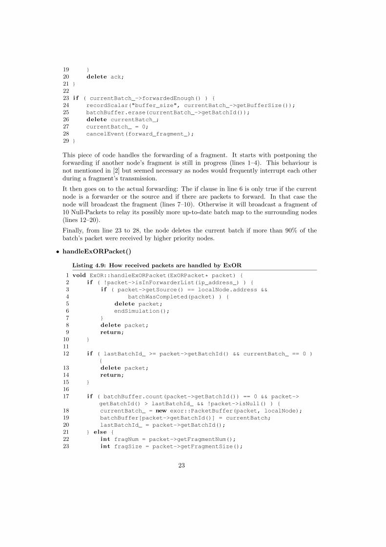
Packet handling starts with checking whether the current node is in the forwarder list (line1). If it is not, then it will check whether it is the packet’s source8 and whether the packet’sbatch map indicates that the batch was successfully received by the destination (line 3 and4). In that case the node will end the simulation. Otherwise it will just return from themethod.
If the current node is in the forwarder list, it will first check whether the packet belongs toan outdated batch. In that case the method exits (line 12–15).
If the node does not yet have a buffer for this batch, the batch is not outdated and thepacket is not a Null-Packet, then the node creates a new packet buffer for the packet’sbatch (lines 17–21). Line 27 to 29: If the packet has already been received or if it is just aNull-Packet, then just its batch map will be looked at and the packet discarded. Otherwisethe packet will be stored in the buffer in line 31.
After taking care of the packet, the node will use the information in the packet header toestimate the current forwarder’s data rate and then schedule its next transmission (lines34–38).
• estimateDataRate()
Listing 4.10: Estimate data rate
1 double ExOR::estimateDataRate(Node forwarder, int fragmentSize, intfragmentNum) {
2 i f (currentForwarder != forwarder) {3 currentForwarder = forwarder;4 currentRate = -1.0;5 return -1.0; // not ready to g i ve es t imat ion6 }78 i f ((simTime() - currentBatch->getLastReception()) < 0.000001) {9 return currentRate;
10 }
8The source is not included in the forwarder list and the source of a batch packet stays the same throughouta batch’s lifetime. Only the forwarder number in the header changes.
24
1112 double rate = 1 / (simTime() - currentBatch->getLastReception());1314 i f (currentRate > 0) {15 currentRate = ALPHA * rate + (1 - ALPHA) * currentRate;16 } else {17 currentRate = rate; // f i r s t ra te es t imat ion18 }1920 return currentRate;21 }
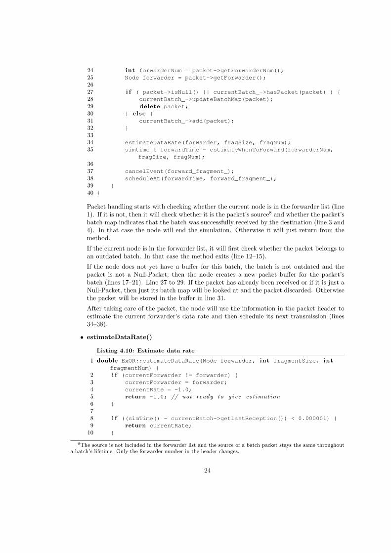
If this is the first packet in a fragment, there can be no estimation of a forwarder’s datarate. Therefore the method exits and sets the current rate to -1.0 (lines 2–5).
It is also not possible to give a new estimation if the interval between packet reception isbelow a certain threshold. In that case the current rate stays untouched (lines 8–10).
In line 12 the data rate between the current and the last reception is computed. If thecurrent rate is larger than zero, that is, if the last reception was not the first reception, thenthe EWMA9 formula is used to estimate the current rate. Otherwise the rate computed inline 12 is taken as the current rate.
• estimateWhenToForward()
Listing 4.11: Estimate when to forward fragment
1 simtime_t ExOR::estimateWhenToForward(int forwarderNum, doublenumPacketsLeft) {
2 double backoffTime = 0;3 double DEFAULT_BACKOFF_TIME = 5.0 * currentBatch_->ONE_PKT_TIME;45 i f (currentRate_ < RATE_TH) {6 backoffTime += DEFAULT_BACKOFF_TIME;7 } else {8 backoffTime += numPacketsLeft / currentRate_;9 }
1011 i f ( forwarderNum - 2 != currentBatch_->getLocalPriority() ) {12 int numHigherPriorityNodes = currentBatch_->getNumForwarders()
- currentBatch_->getLocalPriority() - 1;1314 backoffTime += DEFAULT_BACKOFF_TIME * numHigherPriorityNodes;15 }16 return simTime() + backoffTime;17 }
First the method adds a delay for the current forwarder. If the current rate is invalid, thedefault back off time is used. Otherwise the fragment information from the packet’s headerand the current rate are used to estimate the amount of time it takes the current forwarderto finish its fragment (lines 5–9).
Then if the current forwarder is not the next higher priority node in the forwarder list, thenode adds the default back off time for each higher priority node (lines 11–15).
9Exponential weighted moving average
25
Finally it returns the simulation time when the node should start transmitting its fragment.
Although only one node is supposed to transmit at any time, the rather low default backoff time of five packet transmission times often leads to simultaneous transmissions andnodes being interrupted in the middle of their fragment.
• cullForwarderSet()Having too many forwarders degrades overall throughput because a lot of nodes just trans-mit Null-packets without actually contributing to the forwarding process. To counter thisthe authors of ExOR say in [2, p. 22] that “the source runs a rough simulation of deliveryusing a complete prioritized forwarder set and selects the nodes which transmit at least10% of the total transmissions in a batch”.
For lack of a more detailed description, we implemented the simulation as follows. Assuminga batch size of n, the source starts by broadcasting n packets. Exploiting a node’s knowledgeabout the delivery probability pi to its one-hop neighbours, the number of packets receivedby each of its one hop neighbors is pi ·n. Then the next node in the forwarder list broadcastsas many packets n′ as it has received during the last reception. The number of packets thisnode’s neighbours receive is pi · n′. Then follows the next node in the forwarder list andso on. The simulation ends after 10 iterations over the forwarder list or if the destinationreceived all the packets. In the end the total number of transmissions is computed and nodesthat contributed less than 10% towards the total number of transmissions are removed fromthe forwarder set.
The removal of some of the forwarders using the above simulation resulted in a higher batchtransmission delay than if the forwarder set was left untouched. This suggests that nodesvital for the forwarding were removed and that the above modelling should be improved.
But modelling, for instance, exactly which packet of a batch is lost during a transmissionwould add a lot of complexity which, depending on the deployment scenario, might requiretoo much computing power considering its benefits.
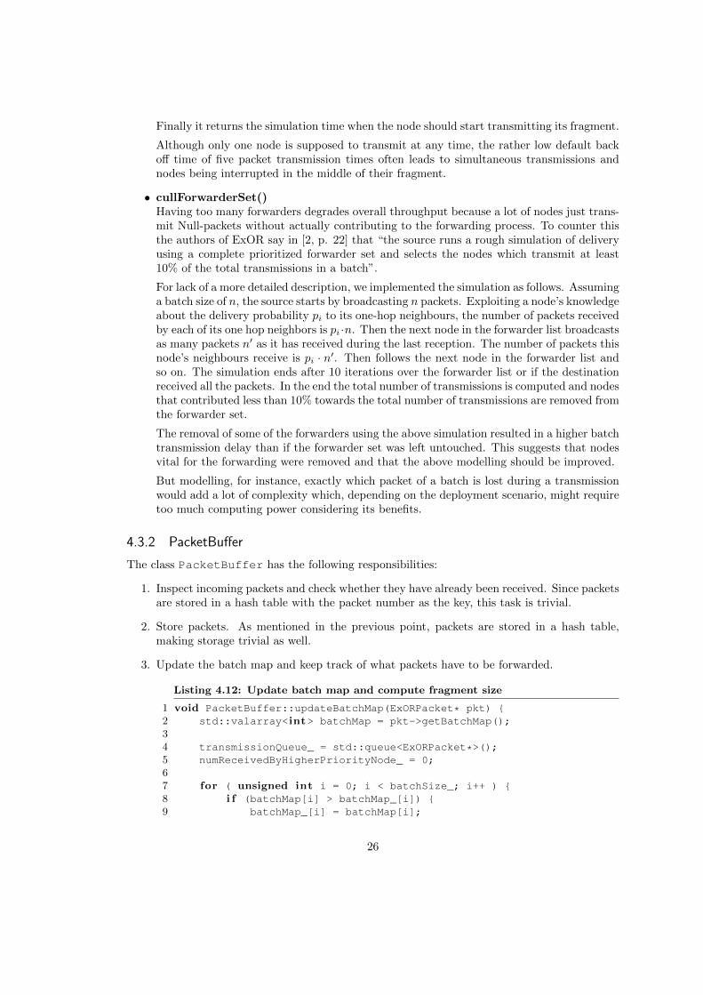
4.3.2 PacketBuffer
The class PacketBuffer has the following responsibilities:
1. Inspect incoming packets and check whether they have already been received. Since packetsare stored in a hash table with the packet number as the key, this task is trivial.
2. Store packets. As mentioned in the previous point, packets are stored in a hash table,making storage trivial as well.
3. Update the batch map and keep track of what packets have to be forwarded.
Listing 4.12: Update batch map and compute fragment size
1 void PacketBuffer::updateBatchMap(ExORPacket* pkt) {2 std::valarray<int> batchMap = pkt->getBatchMap();34 transmissionQueue_ = std::queue<ExORPacket*>();5 numReceivedByHigherPriorityNode_ = 0;67 for ( unsigned int i = 0; i < batchSize_; i++ ) {8 i f (batchMap[i] > batchMap_[i]) {9 batchMap_[i] = batchMap[i];
26

10 }1112 i f ( hasPacket(i) && needTransmit(i) && !isForUs() ) {13 scheduleForTransmission(i);14 } else i f ( hasBeenReceivedByHigherPriorityNode(i) ) {15 numReceivedByHigherPriorityNode_++;16 }17 }1819 fragmentSize_ = transmissionQueue_.size();20 }
This method updates the local batch map by comparing it to the one included in thereceived packet. If the forwarder id in the received batch map is higher, it is copied tothe local batch map (line 8–10). That way the node only forwards packets that were notreceived by higher priority nodes. In line 12 to 14 a packet is scheduled for forwarding ifthe node actually has it, if it has not been received by a higher priority node and if thelocal node is not the batch’s destination.
Because the node needs to know the percentage of packets that have already received byhigher priority nodes, those packets are counted in line 14 to 16. Since the fragment size isequal to the number of packets that were not received by a higher priority node and thusdue for transmission, the fragment size is equal to the length of the transmission queue.
4. To provide main class with means to access packets which need to be forwarded when-ever it is the node’s turn to transmit. The main class can access packets due for trans-mission using the ExORPacket* getNextInQueue() method, and the fragment size withint getFragmentSize().
27

Chapter 5
Simulation and Evaluation
5.1 Simulation Setup
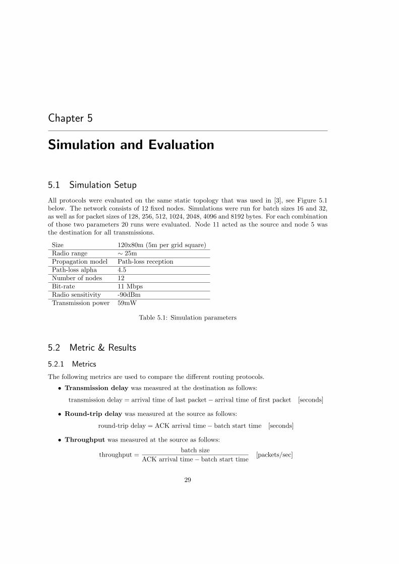
All protocols were evaluated on the same static topology that was used in [3], see Figure 5.1below. The network consists of 12 fixed nodes. Simulations were run for batch sizes 16 and 32,as well as for packet sizes of 128, 256, 512, 1024, 2048, 4096 and 8192 bytes. For each combinationof those two parameters 20 runs were evaluated. Node 11 acted as the source and node 5 wasthe destination for all transmissions.
Size 120x80m (5m per grid square)Radio range ∼ 25mPropagation model Path-loss receptionPath-loss alpha 4.5Number of nodes 12Bit-rate 11 MbpsRadio sensitivity -90dBmTransmission power 59mW
Table 5.1: Simulation parameters
5.2 Metric & Results
5.2.1 Metrics
The following metrics are used to compare the different routing protocols.
• Transmission delay was measured at the destination as follows:
transmission delay = arrival time of last packet− arrival time of first packet [seconds]
• Round-trip delay was measured at the source as follows:
round-trip delay = ACK arrival time− batch start time [seconds]
• Throughput was measured at the source as follows:
throughput =batch size
ACK arrival time− batch start time[packets/sec]
29
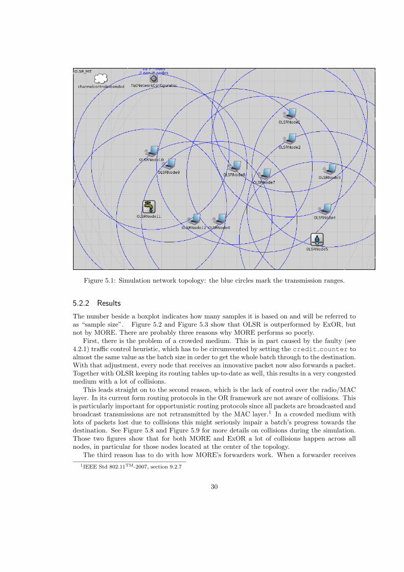
Figure 5.1: Simulation network topology: the blue circles mark the transmission ranges.
5.2.2 Results
The number beside a boxplot indicates how many samples it is based on and will be referred toas “sample size”. Figure 5.2 and Figure 5.3 show that OLSR is outperformed by ExOR, butnot by MORE. There are probably three reasons why MORE performs so poorly.
First, there is the problem of a crowded medium. This is in part caused by the faulty (see4.2.1) traffic control heuristic, which has to be circumvented by setting the credit counter toalmost the same value as the batch size in order to get the whole batch through to the destination.With that adjustment, every node that receives an innovative packet now also forwards a packet.Together with OLSR keeping its routing tables up-to-date as well, this results in a very congestedmedium with a lot of collisions.
This leads straight on to the second reason, which is the lack of control over the radio/MAClayer. In its current form routing protocols in the OR framework are not aware of collisions. Thisis particularly important for opportunistic routing protocols since all packets are broadcasted andbroadcast transmissions are not retransmitted by the MAC layer.1 In a crowded medium withlots of packets lost due to collisions this might seriously impair a batch’s progress towards thedestination. See Figure 5.8 and Figure 5.9 for more details on collisions during the simulation.Those two figures show that for both MORE and ExOR a lot of collisions happen across allnodes, in particular for those nodes located at the center of the topology.
The third reason has to do with how MORE’s forwarders work. When a forwarder receives
1IEEE Std 802.11TM-2007, section 9.2.7
30
an innovative packet and its credit counter is positive, then it will immediately transmit apre-encoded packet. Unfortunately nodes with the same distance to the sender receive the packetalmost at the same time and therefore will try to forward it at almost the same time, which leadsto collisions. In order to avoid synchronisation among forwarders, forwarding a packet is delayedby a random amount of time. This helps to reduce collisions, but on the other hand also increasesthe transmission delay.
ExOR’s performance gain on OLSR might be because its ability to exploit multiple forwarders,the ACK redundancy introduced by the batch map and because it does not need per-packetacknowledgements.
The ranking changes quite a bit in Figure 5.4 and Figure 5.5. OLSR performs best, followedby MORE and then ExOR. ExOR’s rather erratic performance is easily explained: It is onlymeant to deliver 90% of packets in a batch [2, p. 29], so our metric is not really applicable. ExORrelies on the source receiving a batch map which indicates that the destination has received allpackets. The problem is that a forwarder discards a batch and ignores subsequently receivedpackets of that batch, when more than 90% of packets have been received by a higher prioritynode. Since this will happen earlier in a batch’s lifetime, the closer we get to the batch’s source,it is very likely that in a large enough network a lot of forwarders between the source and thedestination already discarded the batch when the destination finally received all the packets andannounces this by transmitting a batch of Null-Packets. Thus this information never reaches thesource. Judging by ExOR’s sample sizes in Figure 5.4 and Figure 5.5, the evaluation networkqualifies as “large enough”. It is not clear where ExOR’s large variance for smaller packet sizescomes from.
Compared to ExOR, MORE’s way of handling ACKs seems to be more efficient. The round-trip time is only slightly higher than the transmission delay, there is only a minor increase invariance and the overall shape of the curve is preserved. It has to be considered that contraryto the specification in [3], forwarders cannot “overhear” an ACK and then discard their batch2.Consequently there is more traffic while the ACK is on its way, which is likely to have somenegative effect on the ACK’s travel time.
There are no surprises in Figure 5.6 and Figure 5.7 because of the way the throughput iscomputed, which is batch size (constant) divided by the round-trip delay, which was discussedin the last section.
In general, batch size does not seem to have any significant effect on performance when theprotocols are evaluated in a simulation environment.
2This is due to the commonly used OMNeT++ node architecture. Protocols are placed above the IP layer,which only forwards unicast packets to upper layers if they are meant for that node. Since the ACK is addressedto the batch’s source, forwarders never learn about it.
31

Figure 5.2: Plot comparing transmission delays of MORE, ExOR and OLSR for batch size 16
32
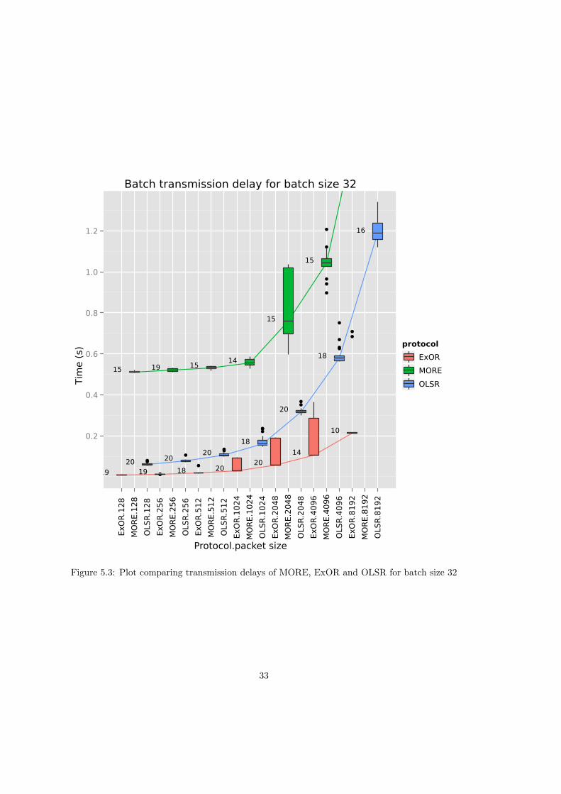
Figure 5.3: Plot comparing transmission delays of MORE, ExOR and OLSR for batch size 32
33
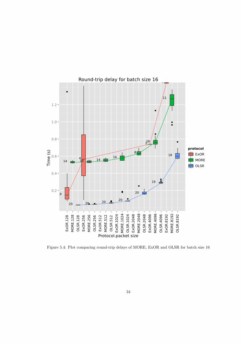
Figure 5.4: Plot comparing round-trip delays of MORE, ExOR and OLSR for batch size 16
34
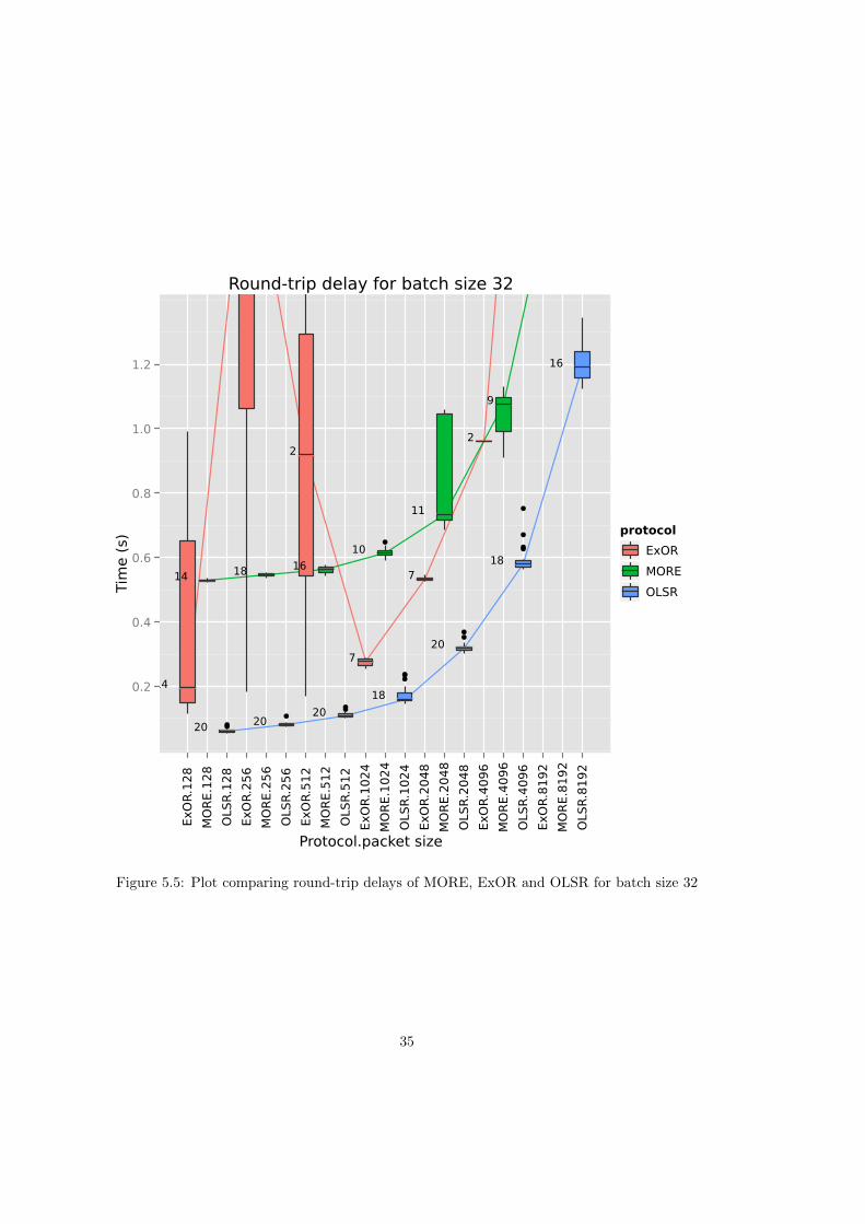
Figure 5.5: Plot comparing round-trip delays of MORE, ExOR and OLSR for batch size 32
35
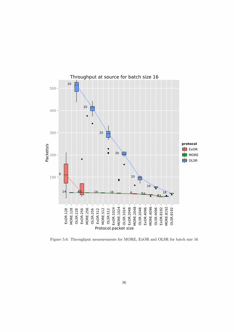
Figure 5.6: Throughput measurements for MORE, ExOR and OLSR for batch size 16
36
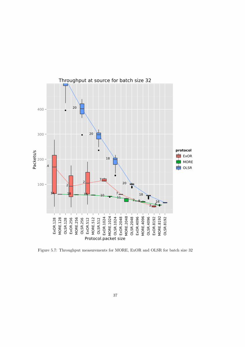
Figure 5.7: Throughput measurements for MORE, ExOR and OLSR for batch size 32
37

Figure 5.8: Number of collisions per node over 558 runs for MORE
38
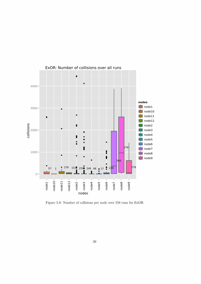
Figure 5.9: Number of collisions per node over 558 runs for ExOR
39

Chapter 6
Conclusion
6.1 Summary & Conclusion
In this thesis we implemented two opportunistic routing protocols MORE and ExOR in OM-NeT++, evaluated their performance and compared them to OLSR. Unfortunately our resultsare not as promising as those in [2] and [3], where significant throughput gains were achievedover traditional routing protocols.
There might be multiple reasons for this outcome. First of all, the descriptions in [2] and [3]do not include all details of their implementations. Although for MORE there is even pseudo-code for two algorithms, there are quite important things left unexplained, such as the “roughsimulation” for reducing the forwarder set in ExOR (see 4.3.1). For MORE, some things areunclear, such as what a forwarder should do when its buffer is full or exactly which tx creditshould be added to a node’s credit counter upon receiving a packet. Furthermore, in thecase of MORE’s traffic control heuristic, the provided algorithm did not work as intended.
The second reason has to do with software architecture. For the usual implementation ofOMNeT++ nodes, the routing protocols sit above the IP layer, not above the MAC layer, asin [3]. In MORE this keeps forwarders from overhearing ACKs, which would cause them todiscard the current batch and thus decrease the medium’s load. Furthermore, in our simulationenvironment, the protocols cannot react to collisions or find out if the medium is free, an abilitywhich is mentioned in both [2] and [3].
Finally, we have to consider the fact that simulation-based evaluations do not necessarilyalign with real-world evaluations. After all, a simulation is always based on a model of realityand thus only an approximation. For example, in discrete event simulators, such as OMNeT++,spatial reuse is not possible because events can only happen one after another, not in parallel.Another problem is a simulation’s sensitivity to even minor changes to its parameters (i.e. thestart and end point or the range of a random delay), which can make all the difference betweena failed and a successful run.
6.2 Future work
The more nodes try to access the medium, the more likely collisions happen. Figure 5.8 andFigure 5.9 clearly show that collisions occur very frequently during the simulation. An obviousway to tackle this issue would be to reduce number of nodes involved in forwarding packets, aclaim that is supported by [2, p. 21–23]’s findings. Therefore future work should investigatemethods to reduce the forwarder set in an attempt to reduce collisions. Future work should alsoinvestigate a cross-layer approach, which enables communication between the routing and theMAC layer. This would allow the routing protocol to learn about collisions and react accordingly.
41

Bibliography
[1] A. Tanenbaum and D. Wetherall, Computer Networks, 5th ed. Prentice Hall, 2011.
[2] S. Biswas, “ExOR: Opportunistic routing in multi-hop wireless networks.” in Proceedingsof ACM SIGCOMM, 2005. [Online]. Available: http://pdos.csail.mit.edu/papers/roofnet:biswas-ms/roofnet biswas-ms.pdf
[3] S. Chachulski, “Trading structure for randomness in wireless opportunistic routing,”Master’s thesis, Massachusetts Institute of Technology, 2005. [Online]. Available:people.csail.mit.edu/szym/sm.pdf
[4] T. B. Zhongliang Zhao, “OMNeT++ based opportunistic routing protocols simulation: Aframework,” in 10th Scandinavian Workshop on Wireless Ad-hoc Networks (ADHOC ’11),2011.
[5] A. Keranen, J. Ott, and T. Karkkainen, “The ONE simulator for DTN protocol evaluation,”in SIMUTools ’09: Proceedings of the 2nd International Conference on Simulation Tools andTechniques, 2009.
[6] A. Varga, “The ONMeT++ discrete event simulation system.” in Proceeding of EuropeanSimulation Multiconference, 2001.
[7] O. Helgason and K. Jonsson, “Opportunistic networking in OMNeT++,” in SIMUTools ’08:Proceedings of the 1st International Conference on Simulation Tools and Techniques, 2008.
[8] D. S. J. De Couto, D. Aguayo, J. Bicket, and R. Morris, “A high-throughput path metricfor multi-hop wireless routing,” in Proceedings of the 9th annual international conference onMobile computing and networking, ser. MobiCom ’03. New York, NY, USA: ACM, 2003,pp. 134–146. [Online]. Available: http://doi.acm.org/10.1145/938985.939000
43


![SOAR: Simple Opportunistic Adaptive Routing Protocol for ...ericrozner.com/papers/soar-tmc.pdf · traditional routing and a seminal opportunistic routing protocol, ExOR [2], under](https://img.pdfslide.us/doc/110x75/603a2ab4a58e7d08225f7730/soar-simple-opportunistic-adaptive-routing-protocol-for-traditional-routing.jpg)