Embed Size (px)
Citation preview

Corporate HeadquartersCisco Systems, Inc.170 West Tasman DriveSan Jose, CA 95134-1706 USAhttp://www.cisco.comTel: 408 526-4000
800 553-NETS (6387)Fax: 408 526-4100
Implementing IPv6 for Cisco IOS Software

THE SPECIFICATIONS AND INFORMATION REGARDING THE PRODUCTS IN THIS MANUAL ARE SUBJECT TO CHANGE WITHOUT NOTICE. ALL STATEMENTS, INFORMATION, AND RECOMMENDATIONS IN THIS MANUAL ARE BELIEVED TO BE ACCURATE BUT ARE PRESENTED WITHOUT WARRANTY OF ANY KIND, EXPRESS OR IMPLIED. USERS MUST TAKE FULL RESPONSIBILITY FOR THEIR APPLICATION OF ANY PRODUCTS.
THE SOFTWARE LICENSE AND LIMITED WARRANTY FOR THE ACCOMPANYING PRODUCT ARE SET FORTH IN THE INFORMATION PACKET THAT SHIPPED WITH THE PRODUCT AND ARE INCORPORATED HEREIN BY THIS REFERENCE. IF YOU ARE UNABLE TO LOCATE THE SOFTWARE LICENSE OR LIMITED WARRANTY, CONTACT YOUR CISCO REPRESENTATIVE FOR A COPY.
The Cisco implementation of TCP header compression is an adaptation of a program developed by the University of California, Berkeley (UCB) as part of UCB’s public domain version of the UNIX operating system. All rights reserved. Copyright © 1981, Regents of the University of California.
NOTWITHSTANDING ANY OTHER WARRANTY HEREIN, ALL DOCUMENT FILES AND SOFTWARE OF THESE SUPPLIERS ARE PROVIDED “AS IS” WITH ALL FAULTS. CISCO AND THE ABOVE-NAMED SUPPLIERS DISCLAIM ALL WARRANTIES, EXPRESSED OR IMPLIED, INCLUDING, WITHOUT LIMITATION, THOSE OF MERCHANTABILITY, FITNESS FOR A PARTICULAR PURPOSE AND NONINFRINGEMENT OR ARISING FROM A COURSE OF DEALING, USAGE, OR TRADE PRACTICE.
IN NO EVENT SHALL CISCO OR ITS SUPPLIERS BE LIABLE FOR ANY INDIRECT, SPECIAL, CONSEQUENTIAL, OR INCIDENTAL DAMAGES, INCLUDING, WITHOUT LIMITATION, LOST PROFITS OR LOSS OR DAMAGE TO DATA ARISING OUT OF THE USE OR INABILITY TO USE THIS MANUAL, EVEN IF CISCO OR ITS SUPPLIERS HAVE BEEN ADVISED OF THE POSSIBILITY OF SUCH DAMAGES.
CCSP, CCVP, the Cisco Square Bridge logo, Follow Me Browsing, and StackWise are trademarks of Cisco Systems, Inc.; Changing the Way We Work, Live, Play, and Learn, and iQuick Study are service marks of Cisco Systems, Inc.; and Access Registrar, Aironet, ASIST, BPX, Catalyst, CCDA, CCDP, CCIE, CCIP, CCNA, CCNP, Cisco, the Cisco Certified Internetwork Expert logo, Cisco IOS, Cisco Press, Cisco Systems, Cisco Systems Capital, the Cisco Systems logo, Cisco Unity, Empowering the Internet Generation, Enterprise/Solver, EtherChannel, EtherFast, EtherSwitch, Fast Step, FormShare, GigaDrive, GigaStack, HomeLink, Internet Quotient, IOS, IP/TV, iQ Expertise, the iQ logo, iQ Net Readiness Scorecard, LightStream, Linksys, MeetingPlace, MGX, the Networkers logo, Networking Academy, Network Registrar, Packet, PIX, Post-Routing, Pre-Routing, ProConnect, RateMUX, ScriptShare, SlideCast, SMARTnet, StrataView Plus, TeleRouter, The Fastest Way to Increase Your Internet Quotient, and TransPath are registered trademarks of Cisco Systems, Inc. and/or its affiliates in the United States and certain other countries.
All other trademarks mentioned in this document or Website are the property of their respective owners. The use of the word partner does not imply a partnership relationship between Cisco and any other company. (0502R)
Implementing IPv6 for Cisco IOS SoftwareCopyright © 2003–2006 Cisco Systems, Inc. All rights reserved.

IPv6-iiiImplementing IPv6 for Cisco IOS
C O N T E N T S
Implementing IPv6 for Cisco IOS Software 1
Implementing Basic Connectivity for IPv6 IPv6c-25
Contents IPv6c-25
Prerequisites for Implementing Basic Connectivity for IPv6 IPv6c-25
Restrictions for Implementing Basic Connectivity for IPv6 IPv6c-28
Information About Implementing Basic Connectivity for IPv6 IPv6c-28
IPv6 for Cisco IOS Software IPv6c-29
Larger IPv6 Address Space for Unique Addresses IPv6c-29
IPv6 Address Formats IPv6c-30
IPv6 Address Type: Unicast IPv6c-31
Aggregatable Global Address IPv6c-31
Site-Local Address IPv6c-32
Link-Local Address IPv6c-33
IPv4-Compatible IPv6 Address IPv6c-33
IPv6 Address Type: Anycast IPv6c-34
IPv6 Address Type: Multicast IPv6c-35
IPv6 Address Output Display IPv6c-36
Simplified IPv6 Packet Header IPv6c-37
CEF and dCEF Switching for IPv6 IPv6c-40
Unicast Reverse Path Forwarding IPv6c-41
NetFlow for IPv6 Environments IPv6c-42
DNS for IPv6 IPv6c-42
Path MTU Discovery for IPv6 IPv6c-43
Cisco Discovery Protocol IPv6 Address Support IPv6c-43
ICMP for IPv6 IPv6c-43
IPv6 Neighbor Discovery IPv6c-44
IPv6 Neighbor Solicitation Message IPv6c-44
IPv6 Router Advertisement Message IPv6c-46
IPv6 Neighbor Redirect Message IPv6c-48
HSRP for IPv6 IPv6c-49
Managing Link, Subnet, and Site Addressing Changes IPv6c-50
IPv6 Stateless Autoconfiguration IPv6c-50
IPv6 General Prefixes IPv6c-51

Contents
IPv6-ivImplementing IPv6 for Cisco IOS
DHCP for IPv6 Prefix Delegation IPv6c-51
Simplified Network Renumbering for IPv6 Hosts IPv6c-55
IPv6 Prefix Aggregation IPv6c-55
IPv6 Site Multihoming IPv6c-56
IPv6 Data Links IPv6c-56
Routed Bridge Encapsulation for IPv6 IPv6c-57
Dual IPv4 and IPv6 Protocol Stacks IPv6c-57
How to Implement Basic Connectivity for IPv6 IPv6c-58
Configuring IPv6 Addressing and Enabling IPv6 Routing IPv6c-58
IPv6 Multicast Groups IPv6c-59
Restrictions IPv6c-59
Enabling an HSRP Group for IPv6 Operation IPv6c-61
Defining and Using IPv6 General Prefixes IPv6c-64
Defining a General Prefix Manually IPv6c-64
Defining a General Prefix Based on a 6to4 Interface IPv6c-64
Defining a General Prefix with the DHCP for IPv6 Prefix Delegation Client Function IPv6c-65
Using a General Prefix IPv6c-66
Configuring IPv4 and IPv6 Protocol Stacks IPv6c-67
Configuring Syslog over IPv6 IPv6c-68
Configuring IPv6 ICMP Rate Limiting IPv6c-69
IPv6 ICMP Rate Limiting IPv6c-69
Configuring the DRP Extension for Traffic Engineering IPv6c-70
Configuring CEF and dCEF Switching for IPv6 IPv6c-71
CEF Switching on Distributed and Nondistributed Architecture Platforms IPv6c-71
Prerequisites IPv6c-71
Restrictions IPv6c-71
Configuring Unicast RPF IPv6c-73
Configuring NetFlow in IPv6 Environments IPv6c-75
Exporting NetFlow Statistics IPv6c-75
Configuring and Customizing the NetFlow Cache IPv6c-77
Customizing the NetFlow Cache IPv6c-77
Managing NetFlow Statistics IPv6c-78
Configuring an Aggregation Cache IPv6c-79
Configuring a NetFlow Minimum Prefix Mask for Router-Based Aggregation IPv6c-81
Configuring the Minimum Mask of a Prefix Aggregation Scheme IPv6c-81
Configuring the Minimum Mask of a Destination-Prefix Aggregation Scheme IPv6c-82
Configuring the Minimum Mask of a Source-Prefix Aggregation Scheme IPv6c-83
Mapping Hostnames to IPv6 Addresses IPv6c-84
Host Name-to-Address Mappings IPv6c-84
Configuring IPv6 ATM and Frame Relay Interfaces IPv6c-86

Contents
IPv6-vImplementing IPv6 for Cisco IOS
IPv6 for Cisco IOS Software Support for Wide-Area Networking Technologies IPv6c-86
IPv6 Addresses and PVCs IPv6c-86
Configuring DHCP for IPv6 IPv6c-90
Configuring the DHCP for IPv6 Server Function IPv6c-90
Configuring the DHCP for IPv6 Client Function IPv6c-91
Configuring DHCP for IPv6 Relay Agent IPv6c-92
Configuring a Database Agent for the Server Function IPv6c-93
Configuring the Stateless DHCP for IPv6 Function IPv6c-94
Restarting the DHCP for IPv6 Client on an Interface IPv6c-97
Deleting Automatic Client Bindings from the DHCP for IPv6 Binding Table IPv6c-97
Troubleshooting DHCP for IPv6 IPv6c-98
Verifying Basic IPv6 Connectivity Configuration and Operation IPv6c-98
IPv6 Redirect Messages IPv6c-99
Examples IPv6c-101
Configuration Examples for Implementing Basic Connectivity for IPv6 IPv6c-108
IPv6 Addressing and IPv6 Routing Configuration Example IPv6c-109
Dual Protocol Stacks Configuration Example IPv6c-109
IPv6 ICMP Rate Limiting Configuration: Example IPv6c-110
CEFv6 and dCEFv6 Configuration: Example IPv6c-110
Configuring NetFlow in IPv6 Environments: Example IPv6c-110
Host Name-to-Address Mappings Configuration: Example IPv6c-111
IPv6 Address to ATM and Frame Relay PVC Mapping Configuration Examples IPv6c-111
IPv6 ATM PVC Mapping Configuration Example—Point-to-Point Interface IPv6c-111
IPv6 ATM PVC Mapping Configuration Example—Point-to-Multipoint Interface IPv6c-112
IPv6 Frame Relay PVC Mapping Configuration Example—Point-to-Point Interface IPv6c-112
IPv6 Frame Relay PVC Mapping Configuration Example—Point-to-Multipoint Interface IPv6c-113
DHCP for IPv6 Configuration Examples IPv6c-114
Configuring the DHCP for IPv6 Server Function: Example IPv6c-114
Configuring the DHCP for IPv6 Client Function: Example IPv6c-115
Configuring a Database Agent for the Server Function: Example IPv6c-115
Configuring the Stateless DHCP for IPv6 Function: Example IPv6c-115
Where to Go Next IPv6c-116
Additional References IPv6c-116
Related Documents IPv6c-116
Standards IPv6c-117
MIBs IPv6c-117
RFCs IPv6c-117
Technical Assistance IPv6c-118

Contents
IPv6-viImplementing IPv6 for Cisco IOS
Implementing Multiprotocol BGP for IPv6 IPv6c-119
Contents IPv6c-119
Prerequisites for Implementing Multiprotocol BGP for IPv6 IPv6c-119
Information About Implementing Multiprotocol BGP for IPv6 IPv6c-120
Multiprotocol BGP Extensions for IPv6 IPv6c-120
Multiprotocol BGP for the IPv6 Multicast Address Family IPv6c-120
6PE Multipath IPv6c-121
How to Implement Multiprotocol BGP for IPv6 IPv6c-121
Configuring an IPv6 BGP Routing Process and BGP Router ID IPv6c-122
Prerequisites IPv6c-122
BGP Router ID for IPv6 IPv6c-122
Configuring an IPv6 Multiprotocol BGP Peer IPv6c-123
Restrictions IPv6c-123
Configuring an IPv6 Multiprotocol BGP Peer Using a Link-Local Address IPv6c-124
Multiprotocol BGP Peering Using Link-Local Addresses IPv6c-125
Restrictions IPv6c-125
Troubleshooting Tips IPv6c-128
Configuring an IPv6 Multiprotocol BGP Peer Group IPv6c-128
Restrictions IPv6c-129
What to Do Next IPv6c-131
Advertising Routes into IPv6 Multiprotocol BGP IPv6c-131
Restrictions IPv6c-131
Configuring a Route Map for IPv6 Multiprotocol BGP Prefixes IPv6c-132
Restrictions IPv6c-132
Redistributing Prefixes into IPv6 Multiprotocol BGP IPv6c-134
Redistribution for IPv6 IPv6c-135
Advertising IPv4 Routes Between IPv6 BGP Peers IPv6c-136
Assigning a BGP Administrative Distance IPv6c-138
Generating Translate Updates for IPv6 Multicast BGP IPv6c-139
Resetting BGP Sessions IPv6c-141
Clearing External BGP Peers IPv6c-141
Clearing IPv6 BGP Route Dampening Information IPv6c-142
Clearing IPv6 BGP Flap Statistics IPv6c-143
Verifying IPv6 Multiprotocol BGP Configuration and Operation IPv6c-143
Output Examples IPv6c-144
Sample Output for the show bgp ipv6 Command IPv6c-145
Sample Output for the show bgp ipv6 summary Command IPv6c-145
Sample Output for the show bgp ipv6 dampened-paths Command IPv6c-145
Sample Output for the debug bgp ipv6 dampening Command IPv6c-146

Contents
IPv6-viiImplementing IPv6 for Cisco IOS
Sample Output for the debug bgp ipv6 updates Command IPv6c-146
Configuration Examples for Multiprotocol BGP for IPv6 IPv6c-147
Configuring a BGP Process, BGP Router ID, and IPv6 Multiprotocol BGP Peer Example IPv6c-147
Configuring an IPv6 Multiprotocol BGP Peer Using a Link-Local Address Example IPv6c-147
Configuring an IPv6 Multiprotocol BGP Peer Group Example IPv6c-148
Advertising Routes into IPv6 Multiprotocol BGP Example IPv6c-148
Configuring a Route Map for IPv6 Multiprotocol BGP Prefixes Example IPv6c-148
Redistributing Prefixes into IPv6 Multiprotocol BGP Example IPv6c-149
Advertising IPv4 Routes Between IPv6 Peers Example IPv6c-149
Where to Go Next IPv6c-149
Additional References IPv6c-149
Related Documents IPv6c-150
Standards IPv6c-150
MIBs IPv6c-150
RFCs IPv6c-150
Technical Assistance IPv6c-151
Implementing EIGRP for IPv6 153
Contents 153
Prerequisites for Implementing EIGRP for IPv6 153
Restrictions for Implementing EIGRP for IPv6 154
Information About Implementing EIGRP for IPv6 154
Cisco EIGRP for IPv6 Implementation 154
How to Implement EIGRP for IPv6 156
Enabling EIGRP for IPv6 on an Interface 156
Configuring the Percentage of Link Bandwidth Used 158
Configuring Summary Aggregate Addresses 159
Configuring EIGRP Route Authentication 160
Changing the Next Hop in EIGRP 161
Adjusting the Interval Between Hello Packets in EIGRP for IPv6 162
Adjusting the Hold Time in EIGRP for IPv6 163
Disabling Split Horizon in EIGRP for IPv6 164
Configuring EIGRP Stub Routing for Greater Stability 165
Configuring a Router for EIGRP Stub Routing 165
Verifying EIGRP Stub Routing 166
Customizing an EIGRP for IPv6 Routing Process 167
Logging EIGRP Neighbor Adjacency Changes 167
Configuring Intervals Between Neighbor Warnings 168
Adjusting the EIGRP for IPv6 Metric Weights 169
Contents
IPv6-viiiImplementing IPv6 for Cisco IOS
Monitoring and Maintaining EIGRP 170
Deleting Entries from EIGRP for IPv6 Routing Tables 170
Using Debugging Commands to Troubleshoot an EIGRP for IPv6 Environment 171
Configuration Examples for Implementing EIGRP for IPv6 172
Configuring EIGRP to Establish Adjacencies on an Interface 172
Where to Go Next 173
Additional References 173
Related Documents 173
Standards 173
MIBs 174
RFCs 174
Technical Assistance 174
Feature Information for Implementing EIGRP for IPv6 174
Configuring GLBP for IPv6 177
Contents 177
Prerequisites for GLBP for IPv6 177
Information About GLBP for IPv6 178
GLBP Overview 178
GLBP Active Virtual Gateway 178
GLBP Virtual MAC Address Assignment 179
GLBP Virtual Gateway Redundancy 180
GLBP Virtual Forwarder Redundancy 180
GLBP Gateway Priority 180
GLBP Gateway Weighting and Tracking 181
GLBP Benefits 181
How to Configure GLBP for IPv6 181
Customizing GLBP 182
Configuring GLBP Authentication 184
How GLBP MD5 Authentication Works 184
Configuring GLBP MD5 Authentication Using a Key String 185
Configuring GLBP MD5 Authentication Using a Key Chain 187
Configuring GLBP Text Authentication 190
Configuring GLBP Weighting Values and Object Tracking 192
Enabling and Verifying GLBP 194
Prerequisites 194
Examples 196
Troubleshooting the Gateway Load Balancing Protocol 196
Prerequisites 197

Contents
IPv6-ixImplementing IPv6 for Cisco IOS
Configuration Examples for GLBP for IPv6 198
Customizing GLBP Configuration: Example 198
GLBP MD5 Authentication Using Key Strings: Example 198
GLBP MD5 Authentication Using Key Chains: Example 199
GLBP Text Authentication: Example 199
GLBP Weighting: Example 199
Enabling GLBP Configuration: Example 199
Additional References 200
Related Documents 200
Standards 200
MIBs 200
RFCs 200
Technical Assistance 201
Glossary 201
Feature Information for GLBP for IPv6 201
Implementing IS-IS for IPv6 IPv6c-203
Contents IPv6c-203
Prerequisites for Implementing IS-IS for IPv6 IPv6c-203
Restrictions for Implementing IS-IS for IPv6 IPv6c-204
Information About Implementing IS-IS for IPv6 IPv6c-204
IS-IS Enhancements for IPv6 IPv6c-205
IS-IS Single-Topology Support for IPv6 IPv6c-205
IS-IS Multitopology Support for IPv6 IPv6c-205
Transition from Single-Topology to Multitopology Support for IPv6 IPv6c-205
IPv6 IS-IS Local RIB IPv6c-206
How to Implement IS-IS for IPv6 IPv6c-206
Configuring Single-Topology IS-IS for IPv6 IPv6c-206
Prerequisites IPv6c-207
Restrictions IPv6c-207
Configuring Multitopology IS-IS for IPv6 IPv6c-208
Prerequisites IPv6c-208
Customizing IPv6 IS-IS IPv6c-210
Redistributing Routes into an IPv6 IS-IS Routing Process IPv6c-212
Redistributing IPv6 IS-IS Routes Between IS-IS Levels IPv6c-213
Disabling IPv6 Protocol-Support Consistency Checks IPv6c-214
Disabling IPv4 Subnet Consistency Checks IPv6c-215
Verifying IPv6 IS-IS Configuration and Operation IPv6c-216
Troubleshooting Tips IPv6c-217

Contents
IPv6-xImplementing IPv6 for Cisco IOS
Examples IPv6c-218
Sample Output for the show ipv6 protocols Command IPv6c-218
Sample Output for the show isis topology Command IPv6c-218
Sample Output for the show clns neighbors Command IPv6c-219
Sample Output for the show clns is-neighbors Command IPv6c-219
Sample Output for the show isis database Command IPv6c-219
Sample Output for the show isis ipv6 rib Command IPv6c-220
Configuration Examples for IPv6 IS-IS IPv6c-221
Configuring Single-Topology IS-IS for IPv6 Example IPv6c-221
Customizing IPv6 IS-IS Example IPv6c-221
Redistributing Routes into an IPv6 IS-IS Routing Process Example IPv6c-221
Redistributing IPv6 IS-IS Routes Between IS-IS Levels Example IPv6c-222
Disabling IPv6 Protocol-Support Consistency Checks Example IPv6c-222
Configuring Multitopology IS-IS for IPv6 Example IPv6c-222
Configuring the IS-IS IPv6 Metric for Multitopology IS-IS Example IPv6c-222
Where to Go Next IPv6c-222
Additional References IPv6c-223
Related Documents IPv6c-224
Standards IPv6c-224
MIBs IPv6c-224
RFCs IPv6c-224
Technical Assistance IPv6c-224
Implementing IPv6 over MPLS IPv6c-225
Contents IPv6c-225
Prerequisites for Implementing IPv6 over MPLS IPv6c-225
Information About Implementing IPv6 over MPLS IPv6c-226
Benefits of Deploying IPv6 over MPLS Backbones IPv6c-226
IPv6 over a Circuit Transport over MPLS IPv6c-226
IPv6 Using Tunnels on the Customer Edge Routers IPv6c-227
IPv6 on the Provider Edge Routers (6PE) IPv6c-228
6PE Multipath IPv6c-229
How to Implement IPv6 over MPLS IPv6c-230
Deploying IPv6 over a Circuit Transport over MPLS IPv6c-230
Deploying IPv6 on the Provider Edge Routers (6PE) IPv6c-230
6PE Network Configuration IPv6c-230
Prerequisites IPv6c-231
Restrictions IPv6c-231
Specifying the Source Address Interface on a 6PE Router IPv6c-231

Contents
IPv6-xiImplementing IPv6 for Cisco IOS
Binding and Advertising the 6PE Label to Advertise Prefixes IPv6c-233
Configuring iBGP Multipath Load Sharing IPv6c-234
Verifying 6PE Configuration and Operation IPv6c-235
Output Examples IPv6c-237
Sample Output for the show bgp ipv6 Command IPv6c-237
Sample Output for the show bgp ipv6 neighbors Command IPv6c-237
Sample Output for the show mpls forwarding-table Command IPv6c-238
Sample Output for the show bgp ipv6 Command IPv6c-238
Sample Output for the show ipv6 cef Command IPv6c-238
Sample Output for the show ipv6 route Command IPv6c-238
Configuration Examples for IPv6 over MPLS IPv6c-239
6PE Configuration Example IPv6c-239
Where to Go Next IPv6c-241
Additional References IPv6c-241
Related Documents IPv6c-242
Standards IPv6c-242
MIBs IPv6c-243
RFCs IPv6c-243
Technical Assistance IPv6c-243
Implementing OSPF for IPv6 IPv6c-245
Contents IPv6c-245
Prerequisites for Implementing OSPF for IPv6 IPv6c-245
Restrictions for Implementing OSPF for IPv6 IPv6c-246
Information About Implementing OSPF for IPv6 IPv6c-246
How OSPF for IPv6 Works IPv6c-247
Comparison of OSPF for IPv6 and OSPF Version 2 IPv6c-247
LSA Types for IPv6 IPv6c-248
NBMA in OSPF for IPv6 IPv6c-249
Force SPF in OSPF for IPv6 IPv6c-249
Load Balancing in OSPF for IPv6 IPv6c-249
Importing Addresses into OSPF for IPv6 IPv6c-250
OSPF for IPv6 Customization IPv6c-250
OSPF for IPv6 Authentication Support with IPSec IPv6c-250
How to Implement OSPF for IPv6 IPv6c-251
Enabling OSPF for IPv6 on an Interface IPv6c-251
Defining an OSPF for IPv6 Area Range IPv6c-252
Prerequisites IPv6c-252
Configuring IPSec on OSPF for IPv6 IPv6c-253

Contents
IPv6-xiiImplementing IPv6 for Cisco IOS
Defining Authentication on an Interface IPv6c-253
Prerequisites IPv6c-253
Defining Authentication in an OSPF Area IPv6c-254
Configuring NBMA Interfaces IPv6c-255
Prerequisites IPv6c-255
Restrictions IPv6c-255
Forcing an SPF Calculation IPv6c-256
Verifying OSPF for IPv6 Configuration and Operation IPv6c-257
Examples IPv6c-258
What to Do Next IPv6c-260
Configuration Examples for Implementing OSPF for IPv6 IPv6c-260
Enabling OSPF for IPv6 on an Interface Configuration: Example IPv6c-260
Defining an OSPF for IPv6 Area Range: Example IPv6c-260
Defining Authentication on an Interface: Example IPv6c-261
Defining Authentication in an OSPF Area: Example IPv6c-261
Configuring NBMA Interfaces Configuration: Example IPv6c-261
Forcing SPF Configuration: Example IPv6c-262
Additional References IPv6c-262
Related Documents IPv6c-263
Standards IPv6c-263
MIBs IPv6c-263
RFCs IPv6c-263
Technical Assistance IPv6c-264
Implementing RIP for IPv6 IPv6c-265
Contents IPv6c-265
Prerequisites for Implementing RIP for IPv6 IPv6c-265
Information About Implementing RIP for IPv6 IPv6c-266
RIP for IPv6 IPv6c-266
How to Implement RIP for IPv6 IPv6c-266
Enabling IPv6 RIP IPv6c-267
Prerequisites IPv6c-267
Customizing IPv6 RIP IPv6c-268
Redistributing Routes into an IPv6 RIP Routing Process IPv6c-269
Configuring Tags for RIP Routes IPv6c-270
Filtering IPv6 RIP Routing Updates IPv6c-271
IPv6 Distribute Lists IPv6c-272
IPv6 Prefix List Operand Keywords IPv6c-272
Verifying IPv6 RIP Configuration and Operation IPv6c-273

Contents
IPv6-xiiiImplementing IPv6 for Cisco IOS
Output Examples IPv6c-274
Sample Output for the show ipv6 rip Command IPv6c-275
Sample Output for the show ipv6 route Command IPv6c-276
Sample Output for the debug ipv6 rip Command IPv6c-276
Configuration Examples for IPv6 RIP IPv6c-277
IPv6 RIP Configuration: Example IPv6c-277
Where to Go Next IPv6c-277
Additional References IPv6c-277
Related Documents IPv6c-278
Standards IPv6c-278
MIBs IPv6c-278
RFCs IPv6c-278
Technical Assistance IPv6c-278
Implementing IPv6 Multicast IPv6c-279
Contents IPv6c-279
Prerequisites for IPv6 Multicast IPv6c-279
Restrictions for IPv6 Multicast IPv6c-281
Information About IPv6 Multicast IPv6c-282
IPv6 Multicast Overview IPv6c-283
IPv6 Multicast Addressing IPv6c-283
IPv6 Multicast Groups IPv6c-285
Scoped Address Architecture IPv6c-285
IPv6 Multicast Routing Implementation IPv6c-286
Multicast Listener Discovery Protocol for IPv6 IPv6c-286
MLD Access Group IPv6c-288
Explicit Tracking of Receivers IPv6c-288
Multicast User Authentication and Profile Support IPv6c-288
Protocol Independent Multicast IPv6c-288
PIM-Sparse Mode IPv6c-289
PIM-Source Specific Multicast IPv6c-292
Routable Address Hello Option IPv6c-294
Bidirectional PIM IPv6c-295
Static Mroutes IPv6c-295
MRIB IPv6c-295
MFIB IPv6c-295
Distributed MFIB IPv6c-296
IPv6 Multicast Process Switching and Fast Switching IPv6c-296
Multiprotocol BGP for the IPv6 Multicast Address Family IPv6c-297

Contents
IPv6-xivImplementing IPv6 for Cisco IOS
How to Implement IPv6 Multicast IPv6c-297
Enabling IPv6 Multicast Routing IPv6c-298
Prerequisites IPv6c-298
Configuring the MLD Protocol IPv6c-298
Customizing and Verifying MLD on an Interface IPv6c-299
Implementing MLD Group Limits IPv6c-301
Configuring Explicit Tracking of Receivers to Track Host Behavior IPv6c-303
Configuring Multicast User Authentication and Profile Support IPv6c-304
Resetting the MLD Traffic Counters IPv6c-307
Clearing the MLD Interface Counters IPv6c-308
Configuring PIM IPv6c-308
Configuring PIM-SM and Displaying PIM-SM Information for a Group Range IPv6c-309
Configuring PIM Options IPv6c-310
Configuring Bidirectional PIM and Displaying Bidirectional PIM Information IPv6c-312
Resetting the PIM Traffic Counters IPv6c-313
Clearing the PIM Topology Table to Reset the MRIB Connection IPv6c-314
Configuring a BSR IPv6c-315
Configuring a BSR and Verifying BSR Information IPv6c-315
Sending PIM RP Advertisements to the BSR IPv6c-316
Configuring BSR for Use Within Scoped Zones IPv6c-317
Configuring BSR Routers to Announce Scope-to-RP Mappings IPv6c-318
Configuring SSM Mapping IPv6c-319
Restrictions IPv6c-319
Configuring Static Mroutes IPv6c-320
Configuring IPv6 Multiprotocol BGP IPv6c-322
Configuring an IPv6 Peer Group to Perform Multicast BGP Routing IPv6c-322
Advertising Routes into IPv6 Multiprotocol BGP IPv6c-324
Redistributing Prefixes into IPv6 Multiprotocol BGP IPv6c-326
Assigning a BGP Administrative Distance IPv6c-327
Generating Translate Updates for IPv6 Multicast BGP IPv6c-328
Resetting BGP Sessions IPv6c-329
Clearing External BGP Peers IPv6c-330
Clearing IPv6 BGP Route Dampening Information IPv6c-331
Clearing IPv6 BGP Flap Statistics IPv6c-331
Using MFIB in IPv6 Multicast IPv6c-332
Verifying MFIB Operation in IPv6 Multicast IPv6c-332
Resetting MFIB Traffic Counters IPv6c-333
Disabling Default Features in IPv6 Multicast IPv6c-334
Disabling Embedded RP Support in IPv6 PIM IPv6c-334
Turning Off IPv6 PIM on a Specified Interface IPv6c-335

Contents
IPv6-xvImplementing IPv6 for Cisco IOS
Disabling MLD Router-Side Processing IPv6c-336
Disabling MFIB on the Router IPv6c-337
Disabling MFIB on a Distributed Platform IPv6c-337
Disabling MFIB Interrupt-Level IPv6 Multicast Forwarding IPv6c-338
Troubleshooting IPv6 Multicast IPv6c-339
Examples IPv6c-341
Configuration Examples for IPv6 Multicast IPv6c-350
Enabling IPv6 Multicast Routing: Example IPv6c-350
Configuring PIM: Examples IPv6c-351
Configuring PIM Options: Example IPv6c-351
Configuring the MLD Protocol: Examples IPv6c-351
Configuring Explicit Tracking of Receivers: Example IPv6c-351
Configuring Mroutes: Example IPv6c-352
Configuring an IPv6 Multiprotocol BGP Peer Group: Example IPv6c-352
Advertising Routes into IPv6 Multiprotocol BGP: Example IPv6c-352
Redistributing Prefixes into IPv6 Multiprotocol BGP: Example IPv6c-352
Generating Translate Updates for IPv6 Multicast BGP: Example IPv6c-352
Disabling Embedded RP Support in IPv6 PIM: Example IPv6c-353
Turning Off IPv6 PIM on a Specified Interface: Example IPv6c-353
Disabling MLD Router-Side Processing: Example IPv6c-353
Disabling and Reenabling MFIB: Example IPv6c-353
Additional References IPv6c-353
Related Documents IPv6c-353
Standards and Drafts IPv6c-354
MIBs IPv6c-355
RFCs IPv6c-355
Technical Assistance IPv6c-355
Managing Cisco IOS Applications over IPv6 IPv6c-357
Contents IPv6c-357
Prerequisites for Managing Cisco IOS Applications over IPv6 IPv6c-357
Information About Managing Cisco IOS Applications over IPv6 IPv6c-358
Telnet Access over IPv6 IPv6c-358
TFTP File Downloading, ping, and traceroute Commands for IPv6 IPv6c-358
SSH over an IPv6 Transport IPv6c-359
SNMP over an IPv6 Transport IPv6c-359
How to Manage Cisco IOS Applications over IPv6 IPv6c-360
Enabling Telnet Access to an IPv6 Router and Establishing a Telnet Session IPv6c-360
What to Do Next IPv6c-361

Contents
IPv6-xviImplementing IPv6 for Cisco IOS
Enabling SSH on an IPv6 Router IPv6c-362
Prerequisites IPv6c-362
Restrictions IPv6c-362
What to Do Next IPv6c-363
Disabling HTTP Access to an IPv6 Router IPv6c-363
What to Do Next IPv6c-364
Configuring an SNMP Notification Server over IPv6 IPv6c-364
What to Do Next IPv6c-366
Configuration Examples for Managing Cisco IOS Applications over IPv6 IPv6c-366
Enabling Telnet Access to an IPv6 Router Configuration: Examples IPv6c-366
Disabling HTTP Access to the Router: Example IPv6c-368
Configuring an SNMP Notification Server: Examples IPv6c-368
Where to Go Next IPv6c-369
Additional References IPv6c-369
Related Documents IPv6c-370
Standards IPv6c-370
MIBs IPv6c-370
RFCs IPv6c-370
Technical Assistance IPv6c-371
Implementing IPSec in IPv6 Security 373
Contents 373
Prerequisites for Implementing IPSec for IPv6 Security 373
Information About Implementing IPSec for IPv6 Security 374
OSPF for IPv6 Authentication Support with IPSec 374
IPSec for IPv6 374
IPv6 IPSec Site-to-Site Protection Using Virtual Tunnel Interface 375
How to Implement IPSec for IPv6 Security 376
Configuring a VTI for Site-to-Site IPv6 IPSec Protection 376
Creating an IKE Policy and a Preshared Key in IPv6 376
Configuring ISAKMP Aggressive Mode 379
Configuring an IPSec Transform Set and IPSec Profile 380
Configuring an ISAKMP Profile in IPv6 381
Configuring IPv6 IPSec VTI 382
Verifying IPSec Tunnel Mode Configuration 384
Troubleshooting IPSec for IPv6 Configuration and Operation 386
Examples 387
Configuration Examples for IPSec for IPv6 Security 390
Configuring a VTI for Site-to-Site IPv6 IPSec Protection: Example 390

Contents
IPv6-xviiImplementing IPv6 for Cisco IOS
Additional References 390
Related Documents 391
Standards 391
MIBs 391
RFCs 392
Technical Assistance 392
Implementing Traffic Filters and Firewalls for IPv6 Security 393
Contents 393
Prerequisites for Implementing Traffic Filters and Firewalls for IPv6 Security 393
Information About Implementing Traffic Filters and Firewalls for IPv6 Security 394
Access Control Lists for IPv6 Traffic Filtering 394
Cisco IOS Firewall for IPv6 394
PAM in Cisco IOS Firewall for IPv6 395
Cisco IOS Firewall Alerts, Audit Trails, and System Logging 395
IPv6 Packet Inspection 396
Tunneling Support 396
Virtual Fragment Reassembly 396
Cisco IOS Firewall Restrictions 396
How to Implement Traffic Filters and Firewalls for IPv6 Security 396
Configuring IPv6 Traffic Filtering 396
Restrictions 396
Creating and Configuring an IPv6 ACL for Traffic Filtering 397
Prerequisites 397
Restrictions 397
Applying the IPv6 ACL to an Interface 399
What to Do Next 399
Creating an IPv6 ACL for Traffic Filtering for Older Releases 399
Restrictions 400
Applying the IPv6 ACL to an Interface in Older Releases 401
Controlling Access to a vty 402
Access Class Filtering in IPv6 402
Creating an IPv6 ACL for Access Class Filtering 402
Applying an IPv6 ACL to the Virtual Terminal Line 404
Configuring Cisco IOS Firewall for IPv6 405
Configuring PAM for IPv6 408
Verifying IPv6 Security Configuration and Operation 411
Troubleshooting IPv6 Security Configuration and Operation 413
Examples 414
Configuration Examples for Implementing Traffic Filters and Firewalls for IPv6 Security 418

Contents
IPv6-xviiImplementing IPv6 for Cisco IOS
Create and Apply IPv6 ACL: Examples 418
Controlling Access to a vty: Example 420
Configuring Cisco IOS Firewall for IPv6: Example 420
Additional References 421
Related Documents 421
Standards 421
MIBs 422
RFCs 422
Technical Assistance 422
Implementing Static Routes for IPv6 IPv6c-423
Contents IPv6c-423
Prerequisites for Implementing Static Routes for IPv6 IPv6c-423
Restrictions for Implementing Static Routes for IPv6 IPv6c-424
Information About Implementing Static Routes for IPv6 IPv6c-424
Static Routes IPv6c-424
Directly Attached Static Routes IPv6c-425
Recursive Static Routes IPv6c-425
Fully Specified Static Routes IPv6c-426
Floating Static Routes IPv6c-426
How to Implement Static Routes for IPv6 IPv6c-426
Configuring a Static IPv6 Route IPv6c-426
Static Routes in IPv6 IPv6c-427
What to Do Next IPv6c-428
Configuring a Floating Static IPv6 Route IPv6c-428
Verifying Static IPv6 Route Configuration and Operation IPv6c-430
Configuration Examples for Implementing Static Routes for IPv6 IPv6c-432
Configuring Manual Summarization Example IPv6c-432
Configuring Traffic Discard Example IPv6c-433
Configuring a Fixed Default Route Example IPv6c-433
Configuring a Floating Static Route Example IPv6c-434
Configuration Examples Using the show ipv6 static, show ipv6 route, and debug ipv6 routing Commands IPv6c-434
Sample Output from the show ipv6 static Command when No Options Are Specified in the Command Syntax IPv6c-435
Sample Output from the show ipv6 static Command with the IPv6 Address and Prefix Command IPv6c-435
Sample Output from the show ipv6 static interface Command IPv6c-436
Sample Output from the show ipv6 static recursive Command IPv6c-436
Sample Output from the show ipv6 static detail Command IPv6c-436

Contents
IPv6-xixImplementing IPv6 for Cisco IOS
Sample Output from the show ipv6 route Command IPv6c-436
Sample Output for the debug ipv6 routing Command IPv6c-437
Where to Go Next IPv6c-437
Additional References IPv6c-438
Related Documents IPv6c-438
Standards IPv6c-438
MIBs IPv6c-438
RFCs IPv6c-439
Technical Assistance IPv6c-439
Implementing ADSL and Deploying Dial Access for IPv6 IPv6c-441
Contents IPv6c-441
Prerequisites for Implementing ADSL and Dial Access for IPv6 IPv6c-441
Restrictions for Implementing ADSL and Deploying Dial Access for IPv6 IPv6c-442
Information About Implementing ADSL and Deploying Dial Access for IPv6 IPv6c-442
Address Assignment for IPv6 IPv6c-442
Stateless Address Autoconfiguration IPv6c-443
Prefix Delegation IPv6c-443
AAA Attributes for IPv6 IPv6c-443
Prerequisites for Using AAA Attributes for IPv6 IPv6c-444
RADIUS Per-User Attributes for Virtual Access in IPv6 Environments IPv6c-444
IPv6 Prefix Pools IPv6c-446
How to Configure ADSL and Deploy Dial Access in IPv6 IPv6c-446
Configuring the NAS IPv6c-446
Troubleshooting Tips IPv6c-449
What to Do Next IPv6c-449
Configuring the Remote CE Router IPv6c-449
What to Do Next IPv6c-451
Configuring the DHCP for IPv6 Server to Obtain Prefixes from RADIUS Servers IPv6c-452
Prerequisites IPv6c-452
Configuring DHCP for IPv6 AAA and SIP Options IPv6c-453
Configuration Examples for Implementing ADSL and Deploying Dial Access for IPv6 IPv6c-454
Implementing ADSL and Deploying Dial Access for IPv6 Example IPv6c-454
Where to Go Next IPv6c-455
Additional References IPv6c-455
Related Documents IPv6c-455
Standards IPv6c-456
MIBs IPv6c-456
RFCs IPv6c-456

Contents
IPv6-xxImplementing IPv6 for Cisco IOS
Technical Assistance IPv6c-457
Implementing NAT Protocol Translation IPv6c-459
Contents IPv6c-459
Prerequisites for Implementing NAT-PT IPv6c-459
Restrictions for Implementing NAT-PT IPv6c-460
Information About Implementing NAT-PT IPv6c-460
NAT-PT IPv6c-460
Static NAT-PT Operation IPv6c-461
Dynamic NAT-PT Operation IPv6c-462
Port Address Translation (PAT) or Overload IPv6c-463
IPv4-Mapped Operation IPv6c-463
How to Implement NAT-PT IPv6c-463
Configuring Basic IPv6 to IPv4 Connectivity for NAT-PT IPv6c-464
NAT-PT Prefix IPv6c-464
Configuring IPv4-Mapped NAT-PT IPv6c-465
Configuring Mappings for IPv6 Hosts Accessing IPv4 Hosts IPv6c-466
What to Do Next IPv6c-469
Configuring Mappings for IPv4 Hosts Accessing IPv6 Hosts IPv6c-469
Configuring Port Address Translation IPv6c-470
What to Do Next IPv6c-472
Verifying NAT-PT Configuration and Operation IPv6c-472
Output Examples IPv6c-473
Sample Output for the show ipv6 nat translations Command IPv6c-474
Sample Output for the show ipv6 nat statistics Command IPv6c-475
Sample Output for the clear ipv6 nat translation Command IPv6c-476
Sample Output for the debug ipv6 nat Command IPv6c-476
Configuration Examples for NAT-PT IPv6c-476
Static NAT-PT Configuration: Example IPv6c-477
Enabling Traffic to be Sent from an IPv6 Network to an IPv4 Network without Using IPv6 Dastination Address Mapping: Example IPv6c-477
Dynamic NAT-PT Configuration for IPv6 Hosts Accessing IPv4 Hosts: Example IPv6c-477
Dynamic NAT-PT Configuration for IPv4 Hosts Accessing IPv6 Hosts Example IPv6c-478
Where to Go Next IPv6c-478
Additional References IPv6c-478
Related Documents IPv6c-479
Standards IPv6c-479
MIBs IPv6c-479
RFCs IPv6c-479

Contents
IPv6-xxiImplementing IPv6 for Cisco IOS
Technical Assistance IPv6c-480
Implementing Policy-Based Routing for IPv6 IPv6c-481
Contents IPv6c-481
Prerequisites for Policy-Based Routing for IPv6 IPv6c-481
Restrictions for Policy-Based Routing for IPv6 IPv6c-482
Information About Policy-Based Routing IPv6c-482
Policy-Based Routing Overview IPv6c-482
How Policy-Based Routing Works IPv6c-483
Packet Matching IPv6c-483
Packet Forwarding Using Set Statements IPv6c-483
When to Use Policy-Based Routing IPv6c-484
How to Implement Policy-Based Routing for IPv6 IPv6c-484
Enabling PBR on an Interface IPv6c-484
Enabling Local PBR for IPv6 IPv6c-487
Enabling Cisco Express Forwarding-Switched PBR for IPv6 IPv6c-487
Verifying Configuration and Operation of PBR for IPv6 IPv6c-488
Troubleshooting PBR for IPv6 IPv6c-488
Examples IPv6c-489
Configuration Examples for Policy-Based Routing for IPv6 IPv6c-489
Enabling PBR on an Interface: Example IPv6c-490
Enabling Local PBR for IPv6: Example IPv6c-490
Additional References IPv6c-490
Related Documents IPv6c-490
MIBs IPv6c-491
Technical Assistance IPv6c-491
Implementing QoS for IPv6 for Cisco IOS Software IPv6c-493
Contents IPv6c-493
Prerequisites for QoS for IPv6 IPv6c-493
Restrictions for QoS for IPv6 IPv6c-494
Information About QoS in IPv6 IPv6c-494
Implementation Strategy for QoS for IPv6 IPv6c-495
Packet Classification in IPv6 IPv6c-495
Policies and Class-Based Packet Marking in IPv6 Networks IPv6c-496
Congestion Management in IPv6 Networks IPv6c-496
Congestion Avoidance for IPv6 Traffic IPv6c-496
Traffic Policing in IPv6 Environments IPv6c-496
How to Implement QoS for IPv6 IPv6c-497

Contents
IPv6-xxiiImplementing IPv6 for Cisco IOS
Restrictions for Classifying Traffic in IPv6 Networks IPv6c-497
Specifying Marking Criteria for IPv6 Packets IPv6c-497
Troubleshooting Tips IPv6c-498
Using the Match Criteria to Manage IPv6 Traffic Flows IPv6c-498
Configuration Examples for Using the Match Criteria to Manage IPv6 Traffic Flows IPv6c-500
Verifying Packet Marking Criteria IPv6c-500
Interpreting Packet Counters in show policy-map interface Command Output IPv6c-500
Confirming the Service Policy IPv6c-505
Configuration Examples for Implementing QoS for IPv6 IPv6c-507
Verification of CEF Switching: Example IPv6c-507
Matching DSCP Value: Example IPv6c-507
Additional References IPv6c-508
Related Documents IPv6c-508
MIBs IPv6c-508
RFCs IPv6c-509
Technical Assistance IPv6c-509
Implementing Tunneling for IPv6 IPv6c-511
Contents IPv6c-511
Prerequisites for Implementing Tunneling for IPv6 IPv6c-511
Restrictions for Implementing Tunneling for IPv6 IPv6c-512
Information About Implementing Tunneling for IPv6 IPv6c-512
Overlay Tunnels for IPv6 IPv6c-513
IPv6 Manually Configured Tunnels IPv6c-514
GRE/IPv4 Tunnel Support for IPv6 Traffic IPv6c-515
GRE/CLNS Tunnel Support for IPv4 and IPv6 Packets IPv6c-515
Automatic 6to4 Tunnels IPv6c-515
Automatic IPv4-Compatible IPv6 Tunnels IPv6c-516
ISATAP Tunnels IPv6c-516
IPv6 IPSec Site-to-Site Protection Using Virtual Tunnel Interface IPv6c-517
How to Implement Tunneling for IPv6 IPv6c-517
Configuring Manual IPv6 Tunnels IPv6c-517
Prerequisites IPv6c-517
What to Do Next IPv6c-519
Configuring GRE IPv6 Tunnels IPv6c-519
Prerequisites IPv6c-519
What to Do Next IPv6c-520
Configuring 6to4 Tunnels IPv6c-520
Prerequisites IPv6c-520

Contents
IPv6-xxiiImplementing IPv6 for Cisco IOS
Restrictions IPv6c-520
What to Do Next IPv6c-522
Configuring IPv4-Compatible IPv6 Tunnels IPv6c-522
Prerequisites IPv6c-522
What to Do Next IPv6c-523
Configuring ISATAP Tunnels IPv6c-523
Prerequisites IPv6c-523
What to Do Next IPv6c-524
Verifying IPv6 Tunnel Configuration and Operation IPv6c-525
Examples IPv6c-525
Configuration Examples for Implementing Tunneling for IPv6 IPv6c-527
Configuring Manual IPv6 Tunnels: Example IPv6c-527
Configuring GRE Tunnels: Examples IPv6c-528
Tunnel Destination Address for IPv6 Tunnel Example IPv6c-528
Configuring CTunnels in GRE mode to Carry IPv6 Packets in CLNS: Example IPv6c-529
Configuring 6to4 Tunnels Example IPv6c-530
Configuring IPv4-Compatible IPv6 Tunnels Example IPv6c-530
Configuring ISATAP Tunnels Example IPv6c-531
Where to Go Next IPv6c-531
Additional References IPv6c-532
Related Documents IPv6c-532
Standards IPv6c-532
MIBs IPv6c-532
RFCs IPv6c-532
Technical Assistance IPv6c-533

Contents
IPv6-xxiImplementing IPv6 for Cisco IOS

IPv6c-25Implementing IPv6 for Cisco IOS Software
Implementing Basic Connectivity for IPv6
Implementing basic IPv6 connectivity in the Cisco IOS software consists of assigning IPv6 addresses to individual router interfaces. The forwarding of IPv6 traffic can be enabled globally, and Cisco Express Forwarding (CEF) switching for IPv6 can also be enabled. Basic connectivity can be enhanced by configuring support for AAAA record types in the Domain Name System (DNS) name-to-address and address-to-name lookup processes, and by managing IPv6 neighbor discovery.
Finding Support Information for Platforms and Cisco IOS Software Images
Use Cisco Feature Navigator to find information about platform support and Cisco IOS software image support. Access Cisco Feature Navigator at http://www.cisco.com/go/fn. You must have an account on Cisco.com. If you do not have an account or have forgotten your username or password, click Cancel at the login dialog box and follow the instructions that appear.
Contents• Prerequisites for Implementing Basic Connectivity for IPv6, page 25
• Restrictions for Implementing Basic Connectivity for IPv6, page 28
• Information About Implementing Basic Connectivity for IPv6, page 28
• How to Implement Basic Connectivity for IPv6, page 58
• Configuration Examples for Implementing Basic Connectivity for IPv6, page 108
• Where to Go Next, page 116
• Additional References, page 116
Prerequisites for Implementing Basic Connectivity for IPv6• This document assumes that you are familiar with IPv4. Refer to the publications referenced in the
“Additional References” section for IPv4 configuration and command reference information.
• The following prerequisites apply to CEFv6 and dCEFv6:
– To forward IPv6 traffic using CEFv6 or dCEFv6, you must configure forwarding of IPv6 unicast datagrams globally on the router by using the ipv6 unicast-routing command in global configuration mode, and you must configure an IPv6 address on an interface by using the ipv6 address command in interface configuration mode.

IPv6c-26
Implementing Basic Connectivity for IPv6Prerequisites for Implementing Basic Connectivity for IPv6
Implementing IPv6 for Cisco IOS Software
– You must enable CEFv4 globally on the router by using the ip cef command in global configuration mode before enabling CEFv6 globally on the router by using the ipv6 cef command in global configuration mode.
– On distributed architecture platforms that support both CEFv6 and dCEFv6, such as the Cisco 7500 series routers, you must enable dCEFv4 globally on the router by using the ip cef distributed command in global configuration mode before enabling dCEFv6 globally on the router by using the ipv6 cef distributed command in global configuration mode.
Note By default, the Cisco 12000 series Internet routers support only dCEFv6.
– To use Unicast RPF, enable CEF switching or dCEF switching in the router. There is no need to configure the input interface for CEF switching. As long as CEF is running on the router, individual interfaces can be configured with other switching modes.
Note For Unicast RPF to work, CEF must be configured globally in the router. Unicast RPF will not work without CEF.
Table 1 identifies the earliest release for each early-deployment train in which each feature became available.
Table 1 Minimum Required Cisco IOS Release
FeatureMinimum Required Cisco IOS Release by Release Train
IPv6 for Cisco IOS 12.2(2)T, 12.0(21)ST, 12.0(22)S, 12.2(14)S, 12.3, 12.3(2)T, 12.4, 12.4(2)T, 12.2(28)SB
IPv6 address formats 12.2(2)T, 12.0(21)ST, 12.0(22)S, 12.2(14)S, 12.3, 12.3(2)T, 12.4, 12.4(2)T, 12.2(28)SB
IPv6 address types: Unicast 12.2(2)T, 12.0(21)ST, 12.0(22)S, 12.2(14)S, 12.3, 12.3(2)T, 12.4, 12.4(2)T, 12.2(28)SB
DNS for IPv61 12.2(2)T, 12.0(21)ST, 12.0(22)S, 12.2(14)S, 12.3, 12.3(2)T, 12.4, 12.4(2)T, 12.2(28)SB
Map host names to IPv6 addresses 12.2(2)T, 12.0(21)ST, 12.0(22)S, 12.2(14)S, 12.3, 12.3(2)T, 12.4, 12.4(2)T, 12.2(28)SB
IPv6 path MTU discovery 12.2(2)T, 12.0(21)ST, 12.0(22)S, 12.2(14)S, 12.3, 12.3(2)T, 12.4, 12.4(2)T, 12.2(28)SB
AAAA DNS lookups over an IPv4 transport 12.2(2)T, 12.0(21)ST, 12.0(22)S, 12.2(14)S, 12.3, 12.3(2)T, 12.4, 12.4(2)T, 12.2(28)SB
ICMPv6 12.2(2)T, 12.0(21)ST, 12.0(22)S, 12.2(14)S, 12.3, 12.3(2)T, 12.4, 12.4(2)T, 12.2(28)SB
IPv6 neighbor discovery2 12.2(2)T, 12.0(21)ST, 12.0(22)S, 12.2(14)S, 12.3, 12.3(2)T, 12.4, 12.4(2)T, 12.2(28)SB
IPv6 stateless autoconfiguration 12.2(2)T, 12.0(21)ST, 12.0(22)S, 12.2(14)S, 12.3, 12.3(2)T, 12.4, 12.4(2)T, 12.2(28)SB
ATM PVC and ATM LANE3 12.2(2)T, 12.0(21)ST, 12.0(22)S, 12.2(14)S, 12.3, 12.3(2)T, 12.4, 12.4(2)T, 12.2(28)SB

IPv6c-27
Implementing Basic Connectivity for IPv6Prerequisites for Implementing Basic Connectivity for IPv6
Implementing IPv6 for Cisco IOS Software
Frame Relay PVC3 12.2(2)T, 12.0(21)ST, 12.0(22)S, 12.2(14)S, 12.3, 12.3(2)T, 12.4, 12.4(2)T, 12.2(28)SB
FDDI 12.2(2)T, 12.2(14)S, 12.3, 12.3(2)T, 12.4, 12.4(2)T, 12.2(28)SB
PPP service over packet over SONET, ISDN, and serial (synchronous and asynchronous) interfaces
12.2(2)T, 12.0(21)ST, 12.0(22)S, 12.2(14)S, 12.3, 12.3(2)T, 12.4, 12.4(2)T, 12.2(28)SB
Ethernet, Fast Ethernet, Gigabit Ethernet, and 10-Gigabit Ethernet
12.2(2)T, 12.0(21)ST, 12.0(22)S, 12.2(14)S, 12.3, 12.3(2)T, 12.4, 12.4(2)T, 12.2(28)SB
Dual IPv4 and IPv6 protocol stacks 12.2(2)T, 12.0(21)ST, 12.0(22)S, 12.2(14)S, 12.3, 12.3(2)T, 12.4, 12.4(2)T, 12.2(28)SB
Configuring IPv6 addressing and enabling IPv6 routing4
12.2(2)T, 12.0(21)ST, 12.0(22)S, 12.2(14)S, 12.3, 12.3(2)T, 12.4, 12.4(2)T, 12.2(28)SB
Cisco High-Level Data Link Control (HDLC) 12.2(2)T, 12.0(21)ST, 12.0(22)S, 12.2(14)S, 12.3, 12.3(2)T, 12.4, 12.4(2)T, 12.2(28)SB
ICMPv6 redirect 12.2(4)T, 12.0(21)ST, 12.0(22)S, 12.2(14)S, 12.3, 12.3(2)T, 12.4, 12.4(2)T, 12.2(28)SB
IPv6 neighbor discovery duplicate address detection
12.2(4)T, 12.0(21)ST, 12.0(22)S, 12.2(14)S, 12.3, 12.3(2)T, 12.4, 12.4(2)T, 12.2(28)SB
DNS lookups over an IPv6 transport 12.2(8)T, 12.0(21)ST, 12.0(22)S, 12.2(14)S, 12.3, 12.3(2)T, 12.4, 12.4(2)T, 12.2(28)SB
ICMPv6 rate limiting 12.2(8)T, 12.0(21)ST, 12.0(22)S, 12.2(14)S, 12.3, 12.3(2)T, 12.4, 12.4(2)T, 12.2(28)SB
CEF and Distributed CEF (dCEF) switching for IPv6
12.0(21)ST, 12.0(22)S, 12.2(13)T, 12.2(14)S, 12.3, 12.3(2)T, 12.4, 12.4(2)T, 12.2(28)SB
CISCO-IP-MIB support 12.0(22)S, 12.2(14)S, 12.2(15)T, 12.3, 12.3(2)T, 12.4, 12.4(2)T, 12.2(28)SB
CISCO-IP-FORWARDING-MIB support 12.0(22)S, 12.2(14)S, 12.2(15)T, 12.3, 12.3(2)T, 12.4, 12.4(2)T, 12.2(28)SB
Dynamic packet transport (DPT) 12.0(23)S
Unicast Reverse Path Forwarding (Unicast RPF) strict mode
12.2(13)T, 12.2(14)S, 12.3, 12.3(2)T, 12.4, 12.4(2)T, 12.2(28)SB
IPv6 address types: Anycast 12.3(4)T, 12.2(25)S, 12.4, 12.4(2)T, 12.2(28)SB
DHCP for IPv6 prefix delegation 12.3(4)T, 12.4, 12.4(2)T
Stateless DHCP for IPv6 12.3(4)T, 12.4, 12.4(2)T
Remote bridged encapsulation (RBE) 12.3(4)T, 12.4, 12.4(2)T
NetFlow for IPv6 12.3(7)T, 12.4, 12.4(2)T
Unicast Reverse Path Forwarding (Unicast RPF) loose mode
12.2(25)S, 12.2(28)SB
DHCP for IPv6 Relay Agent 12.3(11)T, 12.4, 12.4(2)T
IP6.ARPA support was added. 12.3(11)T
Table 1 Minimum Required Cisco IOS Release
FeatureMinimum Required Cisco IOS Release by Release Train

IPv6c-28
Implementing Basic Connectivity for IPv6Restrictions for Implementing Basic Connectivity for IPv6
Implementing IPv6 for Cisco IOS Software
Restrictions for Implementing Basic Connectivity for IPv6• In Cisco IOS Release 12.2(11)T or earlier releases, IPv6 supports only process switching for packet
forwarding. CEF switching and dCEF switching for IPv6 are supported in Cisco IOS Release 12.2(13)T. dCEF switching for IPv6 is supported in Cisco IOS Release 12.0(21)ST.
• IPv6 packets are transparent to Layer 2 LAN switches because the switches do not examine Layer 3 packet information before forwarding IPv6 frames. Therefore, IPv6 hosts can be directly attached to Layer 2 LAN switches.
• In any Cisco IOS release with IPv6 support, multiple IPv6 global and site-local addresses within the same prefix can be configured on an interface. However, multiple IPv6 link-local addresses on an interface are not supported. See the “IPv6 Addressing and IPv6 Routing Configuration Example” section for information on configuring multiple IPv6 global and site-local addresses within the same prefix on an interface.
• The 12.0 S Cisco IOS software release train provides IPv6 support on Cisco 12000 series Internet routers and Cisco 10720 Internet routers only.
Information About Implementing Basic Connectivity for IPv6To configure basic connectivity for IPv6 for Cisco IOS, you must understand the following concepts:
• IPv6 for Cisco IOS Software, page 29
• Larger IPv6 Address Space for Unique Addresses, page 29
• IPv6 Address Formats, page 30
• IPv6 Address Type: Unicast, page 31
• IPv6 Address Type: Anycast, page 34
• IPv6 Address Type: Multicast, page 35
• IPv6 Address Output Display, page 36
• Simplified IPv6 Packet Header, page 37
• CEF and dCEF Switching for IPv6, page 40
• NetFlow for IPv6 Environments, page 42
IPv6 default router preferences 12.4(2)T
Syslog for IPv6 12.4(4)T
HSRP for IPv6 12.4(4)T
1. DNS over IPv6 support was added in Cisco IOS Release 12.2(8)T.
2. Static cache support was added in Cisco IOS Release 12.2(8)T.
3. Cisco Discovery Protocol support was added in Cisco IOS Release 12.2(8)T and Cisco IOS Release 12.2(14)S but is not in the 12.0 ST or 12.0 S trains.
4. MAC address support was added in Cisco IOS Release 12.2(4)T.
Table 1 Minimum Required Cisco IOS Release
FeatureMinimum Required Cisco IOS Release by Release Train

IPv6c-29
Implementing Basic Connectivity for IPv6Information About Implementing Basic Connectivity for IPv6
Implementing IPv6 for Cisco IOS Software
• DNS for IPv6, page 42
• Path MTU Discovery for IPv6, page 43
• Cisco Discovery Protocol IPv6 Address Support, page 43
• ICMP for IPv6, page 43
• IPv6 Neighbor Discovery, page 44
• Managing Link, Subnet, and Site Addressing Changes, page 50
• Simplified Network Renumbering for IPv6 Hosts, page 55
• IPv6 Prefix Aggregation, page 55
• IPv6 Site Multihoming, page 56
• IPv6 Data Links, page 56
• Routed Bridge Encapsulation for IPv6, page 57
• Dual IPv4 and IPv6 Protocol Stacks, page 57
IPv6 for Cisco IOS SoftwareIPv6, formerly named IPng (next generation) is the latest version of the Internet Protocol (IP). IP is a packet-based protocol used to exchange data, voice, and video traffic over digital networks. IPv6 was proposed when it became clear that the 32 bit addressing scheme of IP version 4 (IPv4) was inadequate to meet the demands of Internet growth. After extensive discussion it was decided to base IPng on IP but add a much larger address space and improvements such as a simplified main header and extension headers. IPv6 is described initially in RFC 2460, Internet Protocol, Version 6 (IPv6) Specification issued by the Internet Engineering Task Force (IETF). Further RFCs describe the architecture and services supported by IPv6.
The architecture of IPv6 has been designed to allow existing IPv4 users to transition easily to IPv6 while providing services such as end-to-end security, Quality of Service (QoS), and globally unique addresses. The larger IPv6 address space allows networks to scale and provide global reachability. The simplified IPv6 packet header format handles packets more efficiently. IPv6 prefix aggregation, simplified network renumbering, and IPv6 site multihoming capabilities provide an IPv6 addressing hierarchy that allows for more efficient routing. IPv6 supports widely deployed routing protocols such as RIP, IS-IS, OSPFv3, and multiprotocol BGP. Stateless autoconfiguration is available, enhanced support for Mobile IP is available, and an increased number of multicast addresses is now available.
Larger IPv6 Address Space for Unique AddressesThe primary motivation for IPv6 is the need to meet the anticipated future demand for globally unique IP addresses. Applications such as mobile Internet-enabled devices (such as personal digital assistants [PDAs], telephones, and cars), home-area networks (HANs), and wireless data services are driving the demand for globally unique IP addresses. IPv6 quadruples the number of network address bits from 32 bits (in IPv4) to 128 bits, which provides more than enough globally unique IP addresses for every networked device on the planet. By being globally unique, IPv6 addresses inherently enable global reachability and end-to-end security for networked devices, functionality that is crucial to the applications and services that are driving the demand for the addresses. Additionally, the flexibility of the IPv6 address space reduces the need for private addresses and the use of Network Address Translation (NAT); therefore, IPv6 enables new application protocols that do not require special processing by border routers at the edge of networks.

IPv6c-30
Implementing Basic Connectivity for IPv6Information About Implementing Basic Connectivity for IPv6
Implementing IPv6 for Cisco IOS Software
IPv6 Address FormatsIPv6 addresses are represented as a series of 16-bit hexadecimal fields separated by colons (:) in the format: x:x:x:x:x:x:x:x. Following are two examples of IPv6 addresses:
2001:0DB8:7654:3210:FEDC:BA98:7654:3210
2001:0DB8:0:0:8:800:200C:417A
It is common for IPv6 addresses to contain successive hexadecimal fields of zeros. To make IPv6 addresses less cumbersome, two colons (::) may be used to compress successive hexadecimal fields of zeros at the beginning, middle, or end of an IPv6 address (the colons represent successive hexadecimal fields of zeros). Table 2 lists compressed IPv6 address formats.
A double colon may be used as part of the ipv6-address argument when consecutive 16-bit values are denoted as zero. You can configure multiple IPv6 addresses per interfaces, but only one link-local address.
Note Two colons (::) can be used only once in an IPv6 address to represent the longest successive hexadecimal fields of zeros.
The hexadecimal letters in IPv6 addresses are not case-sensitive.
The loopback address listed in Table 2 may be used by a node to send an IPv6 packet to itself. The loopback address in IPv6 functions the same as the loopback address in IPv4 (127.0.0.1).
Note The IPv6 loopback address cannot be assigned to a physical interface. A packet that has the IPv6 loopback address as its source or destination address must remain within the node that created the packet. IPv6 routers do not forward packets that have the IPv6 loopback address as their source or destination address.
The unspecified address listed in Table 2 indicates the absence of an IPv6 address. For example, a newly initialized node on an IPv6 network may use the unspecified address as the source address in its packets until it receives its IPv6 address.
Note The IPv6 unspecified address cannot be assigned to an interface. The unspecified IPv6 addresses must not be used as destination addresses in IPv6 packets or the IPv6 routing header.
An IPv6 address prefix, in the format ipv6-prefix/prefix-length, can be used to represent bit-wise contiguous blocks of the entire address space. The ipv6-prefix must be in the form documented in RFC 2373 where the address is specified in hexadecimal using 16-bit values between colons. The prefix
Table 2 Compressed IPv6 Address Formats
IPv6 Address Type Preferred Format Compressed Format
Unicast 2001:0:0:0:0DB8:800:200C:417A 2001::0DB8:800:200C:417A
Multicast FF01:0:0:0:0:0:0:101 FF01::101
Loopback 0:0:0:0:0:0:0:1 ::1
Unspecified 0:0:0:0:0:0:0:0 ::

IPv6c-31
Implementing Basic Connectivity for IPv6Information About Implementing Basic Connectivity for IPv6
Implementing IPv6 for Cisco IOS Software
length is a decimal value that indicates how many of the high-order contiguous bits of the address comprise the prefix (the network portion of the address). For example, 2001:0DB8:8086:6502::/32 is a valid IPv6 prefix.
IPv6 Address Type: UnicastAn IPv6 unicast address is an identifier for a single interface, on a single node. A packet that is sent to a unicast address is delivered to the interface identified by that address. The Cisco IOS software supports the following IPv6 unicast address types:
• Global aggregatable address
• Site-local address (proposal to remove by IETF)
• Link-local address
• IPv4-compatible IPv6 address
Aggregatable Global Address
An aggregatable global address is an IPv6 address from the aggregatable global unicast prefix. The structure of aggregatable global unicast addresses enables strict aggregation of routing prefixes that limits the number of routing table entries in the global routing table. Aggregatable global addresses are used on links that are aggregated upward through organizations, and eventually to the Internet service providers (ISPs).
Aggregatable global IPv6 addresses are defined by a global routing prefix, a subnet ID, and an interface ID. Except for addresses that start with binary 000, all global unicast addresses have a 64-bit interface ID. The current global unicast address allocation uses the range of addresses that start with binary value 001 (2000::/3). Figure 1 shows the structure of an aggregatable global address.
Figure 1 Aggregatable Global Address Format
Addresses with a prefix of 2000::/3 (001) through E000::/3 (111) are required to have 64-bit interface identifiers in the extended universal identifier (EUI)-64 format. The Internet Assigned Numbers Authority (IANA) allocates the IPv6 address space in the range of 2000::/16 to regional registries.
The aggregatable global address typically consists of a 48-bit global routing prefix and a 16-bit subnet ID or Site-Level Aggregator (SLA). In the IPv6 aggregatable global unicast address format document (RFC 2374), the global routing prefix included two other hierarchically structured fields named Top-Level Aggregator (TLA) and Next-Level Aggregator (NLA).The IETF decided to remove the TLS and NLA fields form the RFCs because these fields are policy-based. Some existing IPv6 networks deployed before the change might still be using networks based on the older architecture.
8811
9Interface IDGlobal Routing Prefix SLA
45 bits
001
16 bits 64 bits3
Provider Site Host

IPv6c-32
Implementing Basic Connectivity for IPv6Information About Implementing Basic Connectivity for IPv6
Implementing IPv6 for Cisco IOS Software
A 16-bit subnet field called the subnet ID could be used by individual organizations to create their own local addressing hierarchy and to identify subnets. A subnet ID is similar to a subnet in IPv4, except that an organization with an IPv6 subnet ID can support up to 65,535 individual subnets.
An interface ID is used to identify interfaces on a link. The interface ID must be unique to the link. They may also be unique over a broader scope. In many cases, an interface ID will be the same as or based on the link-layer address of an interface. Interface IDs used in aggregatable global unicast and other IPv6 address types must be 64 bits long and constructed in the modified EUI-64 format.
Interface IDs are constructed in the modified EUI-64 format in one of the following ways:
• For all IEEE 802 interface types (for example, Ethernet, and FDDI interfaces), the first three octets (24 bits) are taken from the Organizationally Unique Identifier (OUI) of the 48-bit link-layer address (MAC address) of the interface, the fourth and fifth octets (16 bits) are a fixed hexadecimal value of FFFE, and the last three octets (24 bits) are taken from the last three octets of the MAC address. The construction of the interface ID is completed by setting the Universal/Local (U/L) bit—the seventh bit of the first octet—to a value of 0 or 1. A value of 0 indicates a locally administered identifier; a value of 1 indicates a globally unique IPv6 interface identifier.
• For all other interface types (for example, serial, loopback, ATM, Frame Relay, and tunnel interface types—except tunnel interfaces used with IPv6 overlay tunnels), the interface ID is constructed in the same way as the interface ID for IEEE 802 interface types; however, the first MAC address from the pool of MAC addresses in the router is used to construct the identifier (because the interface does not have a MAC address).
• For tunnel interface types that are used with IPv6 overlay tunnels, the interface ID is the IPv4 address assigned to the tunnel interface with all zeros in the high-order 32 bits of the identifier.
Note For interfaces using PPP, given that the interfaces at both ends of the connection might have the same MAC address, the interface identifiers used at both ends of the connection are negotiated (picked randomly and, if necessary, reconstructed) until both identifiers are unique. The first MAC address in the router is used to construct the identifier for interfaces using PPP.
If no IEEE 802 interface types are in the router, link-local IPv6 addresses are generated on the interfaces in the router in the following sequence:
1. The router is queried for MAC addresses (from the pool of MAC addresses in the router).
2. If no MAC addresses are available in the router, the serial number of the router is used to form the link-local addresses.
3. If the serial number of the router cannot be used to form the link-local addresses, the router uses a Message Digest 5 (MD5) hash to determine the MAC address of the router from the host name of the router.
Site-Local Address
A site-local address is an IPv6 unicast address that uses the prefix FEC0::/10 (1111 1110 11) and concatenates the subnet identifier (the 16-bit SLA field) with the interface identifier in the modified EUI-64 format. Site-local addresses can be used to number a complete site without using a globally unique prefix. Site-local addresses can be considered private addresses because they can be used to restrict communication to a limited domain. Figure 2 shows the structure of a site-local address.
IPv6 routers must not forward packets that have site-local source or destination addresses outside of the site.

IPv6c-33
Implementing Basic Connectivity for IPv6Information About Implementing Basic Connectivity for IPv6
Implementing IPv6 for Cisco IOS Software
Figure 2 Site-Local Address Format
Link-Local Address
A link-local address is an IPv6 unicast address that can be automatically configured on any interface using the link-local prefix FE80::/10 (1111 1110 10) and the interface identifier in the modified EUI-64 format. Link-local addresses are used in the neighbor discovery protocol and the stateless autoconfiguration process. Nodes on a local link can use link-local addresses to communicate; the nodes do not need site-local or globally unique addresses to communicate. Figure 3 shows the structure of a link-local address.
IPv6 routers must not forward packets that have link-local source or destination addresses to other links.
Figure 3 Link-Local Address Format
IPv4-Compatible IPv6 Address
An IPv4-compatible IPv6 address is an IPv6 unicast address that has zeros in the high-order 96 bits of the address and an IPv4 address in the low-order 32 bits of the address. The format of an IPv4-compatible IPv6 address is 0:0:0:0:0:0:A.B.C.D or ::A.B.C.D. The entire 128-bit IPv4-compatible IPv6 address is used as the IPv6 address of a node and the IPv4 address embedded in the low-order 32 bits is used as the IPv4 address of the node. IPv4-compatible IPv6 addresses are assigned to nodes that support both the IPv4 and IPv6 protocol stacks and are used in automatic tunnels. Figure 4 shows the structure of an IPv4-compatible IPv6 address and a few acceptable formats for the address.
5266
8
64 bits128 bits
10 bits
16 bits
1111 1110 11 Subnet ID
Interface ID0
FEC0::/10
5266
9
128 bits
10 bits
1111 1110 10
Interface ID0
FE80::/10

IPv6c-34
Implementing Basic Connectivity for IPv6Information About Implementing Basic Connectivity for IPv6
Implementing IPv6 for Cisco IOS Software
Figure 4 IPv4-Compatible IPv6 Address Format
IPv6 Address Type: AnycastAn anycast address is an address that is assigned to a set of interfaces that typically belong to different nodes. A packet sent to an anycast address is delivered to the closest interface—as defined by the routing protocols in use—identified by the anycast address. Anycast addresses are syntactically indistinguishable from unicast addresses because anycast addresses are allocated from the unicast address space. Assigning a unicast address to more than one interface makes a unicast address an anycast address. Nodes to which the anycast address is assigned must be explicitly configured to recognize that the address is an anycast address.
Note Anycast addresses can be used only by a router, not a host, and anycast addresses must not be used as the source address of an IPv6 packet.
Figure 5 shows the format of the subnet router anycast address; the address has a prefix concatenated by a series of zeros (the interface ID). The subnet router anycast address can be used to reach a router on the link that is identified by the prefix in the subnet router anycast address.
Figure 5 Subnet Router Anycast Address Format
The following shows the configuration for an anycast prefix for 6to4 relay routers:
interface Tunnel0no ip addressipv6 address 2001:0DB8:A00:1::1/64ipv6 address 2001:oDB8:c058:6301::/128 anycasttunnel source Ethernet0tunnel mode ipv6ip 6to4! interface Ethernet0ip address 10.0.0.1 255.255.255.0ip address 192.88.99.1 255.255.255.0 secondary ! ipv6 route 2001:0DB8::/16 Tunnel0 !
5272
7
::192.168.30.1= ::C0A8:1E01
IPv4 address0
96 bits 32 bits
5267
0
128 bits
0000000000000...000Prefix

IPv6c-35
Implementing Basic Connectivity for IPv6Information About Implementing Basic Connectivity for IPv6
Implementing IPv6 for Cisco IOS Software
IPv6 Address Type: MulticastAn IPv6 multicast address is an IPv6 address that has a prefix of FF00::/8 (1111 1111). An IPv6 multicast address is an identifier for a set of interfaces that typically belong to different nodes. A packet sent to a multicast address is delivered to all interfaces identified by the multicast address. The second octet following the prefix defines the lifetime and scope of the multicast address. A permanent multicast address has a lifetime parameter equal to 0; a temporary multicast address has a lifetime parameter equal to 1. A multicast address that has the scope of a node, link, site, or organization, or a global scope has a scope parameter of 1, 2, 5, 8, or E, respectively. For example, a multicast address with the prefix FF02::/16 is a permanent multicast address with a link scope. Figure 6 shows the format of the IPv6 multicast address.
Figure 6 IPv6 Multicast Address Format
IPv6 nodes (hosts and routers) are required to join (receive packets destined for) the following multicast groups:
• All-nodes multicast group FF02:0:0:0:0:0:0:1 (scope is link-local)
• Solicited-node multicast group FF02:0:0:0:0:1:FF00:0000/104 for each of its assigned unicast and anycast addresses
IPv6 routers must also join the all-routers multicast group FF02:0:0:0:0:0:0:2 (scope is link-local).
The solicited-node multicast address is a multicast group that corresponds to an IPv6 unicast or anycast address. IPv6 nodes must join the associated solicited-node multicast group for every unicast and anycast address to which it is assigned. The IPv6 solicited-node multicast address has the prefix FF02:0:0:0:0:1:FF00:0000/104 concatenated with the 24 low-order bits of a corresponding IPv6 unicast or anycast address. (See Figure 7.) For example, the solicited-node multicast address corresponding to the IPv6 address 2037::01:800:200E:8C6C is FF02::1:FF0E:8C6C. Solicited-node addresses are used in neighbor solicitation messages.
5267
1
128 bits
4 bits4 bits
0 if permanent1 if temporary
Interface ID0
1111 1111
8 bits 8 bits
F F Lifetime Scope Lifetime =
1 = node2 = link5 = site8 = organizationE = global
Scope =

IPv6c-36
Implementing Basic Connectivity for IPv6Information About Implementing Basic Connectivity for IPv6
Implementing IPv6 for Cisco IOS Software
Figure 7 IPv6 Solicited-Node Multicast Address Format
Note There are no broadcast addresses in IPv6. IPv6 multicast addresses are used instead of broadcast addresses.
For further information on IPv6 multicast, refer to the Implementing IPv6 Multicast document in the Cisco IOS IPv6 Configuration Library.
IPv6 Address Output DisplayWhen IPv6 or IPv4 command output displays an IPv6 address, a long IPv6 address can overflow into neighboring fields, causing the output to be difficult to read. The output fields were designed to work with the longest possible IPv4 address, which has 15 characters; IPv6 addresses can be up to 39 characters long. The following scheme has been adopted in IPv4 and IPv6 commands to allow the appropriate length of IPv6 address to be displayed and move the following fields to the next line, if necessary. The fields that are moved are kept in alignment with the header row.
Using the output display from the where command as an example, eight connections are displayed. The first six connections feature IPv6 addresses; the last two connections feature IPv4 addresses.
Router# where
Conn Host Address Byte Idle Conn Name 1 test5 2001:0DB8:3333:4::5 6 24 test5 2 test4 2001:0DB8:3333:44::5 6 24 test4 3 2001:0DB8:3333:4::5 2001:0DB8:3333:4::5 6 24 2001:0DB8:3333:4::5 4 2001:0DB8:3333:44::5 2001:0DB8:3333:44::5 6 23 2001:0DB8:3333:44::5 5 2001:0DB8:3000:4000:5000:6000:7000:8001 2001:0DB8:3000:4000:5000:6000:7000:8001 6 20 2001:0DB8:3000:4000:5000:6000: 6 2001:0DB8:1::1 2001:0DB8:1::1 0 1 2001:0DB8:1::1 7 10.1.9.1 10.1.9.1 0 0 10.1.9.1 8 111.222.111.222 111.222.111.222 0 0 111.222.111.222
Connection 1 contains an IPv6 address that uses the maximum address length in the address field. Connection 2 shows the IPv6 address overflowing the address field and the following fields moved to the next line, but in alignment with the appropriate headers. Connection 3 contains an IPv6 address that fills the maximum length of the host name and address fields without wrapping any lines. Connection 4 shows the effect of both the host name and address fields containing a long IPv6 address. The output is shown over three lines keeping the correct heading alignment. Connection 5 displays a similar effect as
5267
2
128 bits
Interface ID
IPv6 unicast or anycast address
Solicited-node multicast address
Prefix
Lower 24
24 bits
FF02 0 1 FF

IPv6c-37
Implementing Basic Connectivity for IPv6Information About Implementing Basic Connectivity for IPv6
Implementing IPv6 for Cisco IOS Software
connection 4 with a very long IPv6 address in the host name and address fields. Note that the connection name field is actually truncated. Connection 6 displays a very short IPv6 address that does not require any change in the display. Connections 7 and 8 display short and long IPv4 addresses.
Note The IPv6 address output display applies to all commands that display IPv6 addresses.
Simplified IPv6 Packet HeaderThe basic IPv4 packet header has 12 fields with a total size of 20 octets (160 bits). (See Figure 8.) The 12 fields may be followed by an Options field, which is followed by a data portion that is usually the transport-layer packet. The variable length of the Options field adds to the total size of the IPv4 packet header. The shaded fields of the IPv4 packet header shown in Figure 8 are not included in the IPv6 packet header.
Figure 8 IPv4 Packet Header Format
The basic IPv6 packet header has 8 fields with a total size of 40 octets (320 bits). (See Figure 9.) Fields were removed from the IPv6 header because, in IPv6, fragmentation is not handled by routers and checksums at the network layer are not used. Instead, fragmentation in IPv6 is handled by the source of a packet and checksums at the data link layer and transport layer are used. (In IPv4, the User Datagram Protocol (UDP) transport layer uses an optional checksum. In IPv6, use of the UDP checksum is required to check the integrity of the inner packet.) Additionally, the basic IPv6 packet header and Options field are aligned to 64 bits, which can facilitate the processing of IPv6 packets.
Version Hd Len Type of Service Total Length
20octets
Identification Flags Fragment Offset
Time to Live Protocol Header Checksum
Source Address
Destination Address
Data Portion
32 bits
Options Padding Variablelength
5145
7

IPv6c-38
Implementing Basic Connectivity for IPv6Information About Implementing Basic Connectivity for IPv6
Implementing IPv6 for Cisco IOS Software
Figure 9 IPv6 Packet Header Format
Table 3 lists the fields in the basic IPv6 packet header.
Version Traffic Class Flow Label
40octets
Payload Length Next Header Hop Limit
Data Portion
32 bits
Next HeaderVariablelength
5145
8
Source Address
Destination Address
Extension Header information
Table 3 Basic IPv6 Packet Header Fields
Field Description
Version Similar to the Version field in the IPv4 packet header, except that the field lists number 6 for IPv6 instead of number 4 for IPv4.
Traffic Class Similar to the Type of Service field in the IPv4 packet header. The Traffic Class field tags packets with a traffic class that is used in differentiated services.
Flow Label A new field in the IPv6 packet header. The Flow Label field tags packets with a specific flow that differentiates the packets at the network layer.
Payload Length Similar to the Total Length field in the IPv4 packet header. The Payload Length field indicates the total length of the data portion of the packet.
Next Header Similar to the Protocol field in the IPv4 packet header. The value of the Next Header field determines the type of information following the basic IPv6 header. The type of information following the basic IPv6 header can be a transport-layer packet, for example, a TCP or UDP packet, or an Extension Header, as shown in Figure 9.
Hop Limit Similar to the Time to Live field in the IPv4 packet header. The value of the Hop Limit field specifies the maximum number of routers that an IPv6 packet can pass through before the packet is considered invalid. Each router decrements the value by one. Because no checksum is in the IPv6 header, the router can decrement the value without needing to recalculate the checksum, which saves processing resources.

IPv6c-39
Implementing Basic Connectivity for IPv6Information About Implementing Basic Connectivity for IPv6
Implementing IPv6 for Cisco IOS Software
Following the eight fields of the basic IPv6 packet header are optional extension headers and the data portion of the packet. If present, each extension header is aligned to 64 bits. There is no fixed number of extension headers in an IPv6 packet. Together, the extension headers form a chain of headers. Each extension header is identified by the Next Header field of the previous header. Typically, the final extension header has a Next Header field of a transport-layer protocol, such as TCP or UDP. Figure 10 shows the IPv6 extension header format.
Figure 10 IPv6 Extension Header Format
Source Address Similar to the Source Address field in the IPv4 packet header, except that the field contains a 128-bit source address for IPv6 instead of a 32-bit source address for IPv4.
Destination Address Similar to the Destination Address field in the IPv4 packet header, except that the field contains a 128-bit destination address for IPv6 instead of a 32-bit destination address for IPv4.
Table 3 Basic IPv6 Packet Header Fields (continued)
Field Description
IPv6packet
IPv6 basic header(40 octets)
Any number ofextension headers
5145
9
Next Header Ext Header Length
Extension Header Data
Data (for example,TCP or UDP)

IPv6c-40
Implementing Basic Connectivity for IPv6Information About Implementing Basic Connectivity for IPv6
Implementing IPv6 for Cisco IOS Software
Table 4 lists the extension header types and their Next Header field values.
The Cisco IOS system logging (syslog) process in IPv6 allows users to log syslog messages to external syslog servers and hosts with IPv6 addresses. This implementation allows user to specify an IPv4-based logging host (syslog server) by providing the host’s IP address in IPv4 format (for example, 192.168.0.0) or IPv6 format (for example, 2001:0DB8:A00:1::1/64).
The feature is backward compatible with existing IPv4 and new IPv6 addresses and hostnames.
CEF and dCEF Switching for IPv6 CEFv6 is advanced, Layer 3 IP switching technology for the forwarding of IPv6 packets. dCEFv6 performs the same functions as CEFv6 but for distributed architecture platforms such as the Cisco 12000 series Internet routers and the Cisco 7500 series routers. dCEFv6 and CEFv6 function the same and offer the same benefits as for dCEFv4 and CEFv4—network entries that are added, removed, or modified in the IPv6 Routing Information Base (RIB), as dictated by the routing protocols in use, are reflected in the Forwarding Information Bases (FIBs), and the IPv6 adjacency tables maintain Layer 2 next-hop addresses for all entries in each FIB.
Table 4 IPv6 Extension Header Types
Header Type
Next Header Value Description
Hop-by-hop options header 0 This header is processed by all hops in the path of a packet. When present, the hop-by-hop options header always follows immediately after the basic IPv6 packet header.
Destination options header 60 The destination options header can follow any hop-by-hop options header, in which case the destination options header is processed at the final destination and also at each visited address specified by a routing header. Alternatively, the destination options header can follow any Encapsulating Security Payload (ESP) header, in which case the destination options header is processed only at the final destination.
Routing header 43 The routing header is used for source routing.
Fragment header 44 The fragment header is used when a source must fragment a packet that is larger than the Maximum Transmission Unit (MTU) for the path between itself and a destination. The Fragment header is used in each fragmented packet.
Authentication header
and
ESP header
51
50
The Authentication header and the ESP header are used within IP Security Protocol (IPSec) to provide authentication, integrity, and confidentiality of a packet. These headers are identical for both IPv4 and IPv6.
Upper-layer header 6 (TCP)
17 (UDP)
The upper-layer (transport) headers are the typical headers used inside a packet to transport the data. The two main transport protocols are TCP and UDP.
Mobility header 135 Extension headers used by mobile nodes, correspondent nodes, and home agents in all messaging related to the creation and management of bindings.

IPv6c-41
Implementing Basic Connectivity for IPv6Information About Implementing Basic Connectivity for IPv6
Implementing IPv6 for Cisco IOS Software
Note By default, the Cisco 12000 series Internet routers support only dCEFv6 (CEF switching is performed by the line cards). The Cisco 7500 series routers support both CEFv6 and dCEFv6. When CEFv6 is configured on Cisco 7500 series routers, CEF switching is performed by the Route Processor (RP); when dCEFv6 is configured, CEF switching is performed by the line cards.
In Cisco IOS Release 12.0(21)ST, dCEFv6 included support for IPv6 addresses and prefixes. In Cisco IOS Release 12.0(22)S or later releases and Cisco IOS Release 12.2(13)T or later releases, dCEFv6 and CEFv6 were enhanced to include support for separate FIBs for IPv6 global, site-local, and link-local addresses.
Each IPv6 router interface has an association to one IPv6 global FIB, one IPv6 site-local FIB, and one IPv6 link-local FIB (multiple interfaces can have an association to the same FIB). All IPv6 router interfaces that are attached to the same IPv6 link share the same IPv6 link-local FIB. IPv6 packets that have an IPv6 global destination address are processed by the IPv6 global FIB; however, packets that have an IPv6 global destination address and either an IPv6 site-local or link-local source address are sent to the RP for process switching and scope-error handling. IPv6 packets that have a site-local destination address are processed by the IPv6 site-local FIB; however, packets that have a link-local source address are not forwarded off of the local link and are sent to the RP for process switching and scope-error handling.
Unicast Reverse Path Forwarding
Use the Unicast RPF feature to mitigate problems caused by malformed or forged (spoofed) IPv6 source addresses that pass through an IPv6 router. Malformed or forged source addresses can indicate denial-of-service (DoS) attacks based on source IPv6 address spoofing.
When Unicast RPF is enabled on an interface, the router examines all packets received on that interface. The router verifies that the source address appears in the routing table and matches the interface on which the packet was received. This “look backward” ability is available only when CEF is enabled on the router, because the lookup relies on the presence of the Forwarding Information Base (FIB). CEF generates the FIB as part of its operation.
Note Unicast RPF is an input function and is applied only on the input interface of a router at the upstream end of a connection.
The Unicast RPF feature checks whether any packet received at a router interface arrives on one of the best return paths to the source of the packet. The feature performs a reverse lookup in the CEF table. If Unicast RPF does not find a reverse path for the packet, Unicast RPF can drop or forward the packet, depending on whether an access control list (ACL) is specified. If an ACL is specified, then when (and only when) a packet fails the Unicast RPF check, the ACL is checked to verify if the packet should be dropped (using a deny statement in the ACL) or forwarded (using a permit statement in the ACL). Whether a packet is dropped or forwarded, the packet is counted in the global IP traffic statistics for Unicast RPF drops and in the interface statistics for Unicast RPF.
If no ACL is specified, the router drops the forged or malformed packet immediately and no ACL logging occurs. The router and interface Unicast RPF counters are updated.
Unicast RPF events can be logged by specifying the logging option for the ACL entries. Log information can be used to gather information about the attack, such as source address, time, and so on.

IPv6c-42
Implementing Basic Connectivity for IPv6Information About Implementing Basic Connectivity for IPv6
Implementing IPv6 for Cisco IOS Software
Note With Unicast RPF, all equal-cost “best” return paths are considered valid. Unicast RPF works in cases where multiple return paths exist, provided that each path is equal to the others in terms of the routing cost (number of hops, weights, and so on) and as long as the route is in the FIB.
NetFlow for IPv6 EnvironmentsNetFlow enables you to collect traffic flow statistics on your routing devices and analyze traffic patterns, and the data records are used to detect DoS attacks. NetFlow for IPv6 is based on NetFlow Version 9 and functions by identifying packet flows for ingress IP and IPv6 packets. It does not involve any connection-setup protocol between routers or to any other networking device or end station and does not require any change externally—either to the traffic or packets themselves or to any other networking device. NetFlow is completely transparent to the existing network, including end stations and application software and network devices such as LAN switches. Also, NetFlow is performed independently on each internetworking device; it need not be operational on each router in the network. Using NetFlow Data Export (NDE), you can export data to a remote workstation for data collection and further processing. Network planners can selectively invoke NDE on a router or on a per-subinterface basis to gain traffic performance, control, or accounting benefits in specific network locations. NetFlow collects accounting information for IPv6 encapsulation and tunnels. If NetFlow capture is configured on a logical interface, IPv6 flows will be reported with that interface as the input or output interface, depending on whether the feature has been activated on the ingress or egress port.
DNS for IPv6IPv6 supports DNS record types that are supported in the DNS name-to-address and address-to-name lookup processes. The DNS record types support IPv6 addresses.IPv6 also supports the reverse mapping of IPv6 addresses to DNS names.
Note IP6.ARPA support was added in the Cisco IOS 12.3(11)T release. IP6.ARPA is not supported in releases prior to the Cisco IOS 12.3(11)T release.
Table 5 lists the IPv6 DNS record types.
Table 5 IPv6 DNS Record Types
Record Type Description Format
AAAA Maps a host name to an IPv6 address. (Equivalent to an A record in IPv4.)
Note Support for AAAA records and A records over an IPv6 transport or IPv4 transport is in Cisco IOS Release 12.2(8)T or later releases.
www.abc.test AAAA 3FFE:YYYY:C18:1::2
PTR Maps an IPv6 address to a host name. (Equivalent to a PTR record in IPv4.)
Note The Cisco IOS software supports resolution of PTR records for the IP6.INT domain.
2.0.0.0.0.0.0.0.0.0.0.0.0.0.0.0.1.0.0.0.8.1.c.0.y.y.y.y.e.f.f.3.ip6.int PTR www.abc.test

IPv6c-43
Implementing Basic Connectivity for IPv6Information About Implementing Basic Connectivity for IPv6
Implementing IPv6 for Cisco IOS Software
Path MTU Discovery for IPv6As in IPv4, path MTU discovery in IPv6 allows a host to dynamically discover and adjust to differences in the MTU size of every link along a given data path. In IPv6, however, fragmentation is handled by the source of a packet when the path MTU of one link along a given data path is not large enough to accommodate the size of the packets. Having IPv6 hosts handle packet fragmentation saves IPv6 router processing resources and helps IPv6 networks run more efficiently.
Note In IPv4, the minimum link MTU is 68 octets, which means that the MTU size of every link along a given data path must support an MTU size of at least 68 octets.
In IPv6, the minimum link MTU is 1280 octets. We recommend using an MTU value of 1500 octets for IPv6 links.
Cisco Discovery Protocol IPv6 Address SupportThe Cisco Discovery Protocol (formerly known as CDP) IPv6 Address Support for Neighbor Information feature adds the ability to transfer IPv6 addressing information between two Cisco devices using Cisco Discovery Protocol. Cisco Discovery Protocol support for IPv6 addresses allows Cisco Discovery Protocol to exchange IPv6 addressing information. Cisco Discovery Protocol support for IPv6 addresses provides IPv6 information to network management products, and troubleshooting tools.
ICMP for IPv6Internet Control Message Protocol (ICMP) in IPv6 functions the same as ICMP in IPv4—ICMP generates error messages, such as ICMP destination unreachable messages, and informational messages, such as ICMP echo request and reply messages. Additionally, ICMP packets in IPv6 are used in the IPv6 neighbor discovery process, path MTU discovery, and the Multicast Listener Discovery (MLD) protocol for IPv6. MLD is used by IPv6 routers to discover multicast listeners (nodes that want to receive multicast packets destined for specific multicast addresses) on directly attached links. MLD is based on version 2 of the Internet Group Management Protocol (IGMP) for IPv4.
A value of 58 in the Next Header field of the basic IPv6 packet header identifies an IPv6 ICMP packet. ICMP packets in IPv6 are like a transport-layer packet in the sense that the ICMP packet follows all the extension headers and is the last piece of information in the IPv6 packet. Within IPv6 ICMP packets, the ICMPv6 Type and ICMPv6 Code fields identify IPv6 ICMP packet specifics, such as the ICMP message type. The value in the Checksum field is derived (computed by the sender and checked by the receiver) from the fields in the IPv6 ICMP packet and the IPv6 pseudoheader. The ICMPv6 Data field contains error or diagnostic information relevant to IP packet processing. Figure 11 shows the IPv6 ICMP packet header format.
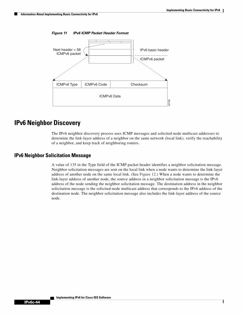
IPv6c-44
Implementing Basic Connectivity for IPv6Information About Implementing Basic Connectivity for IPv6
Implementing IPv6 for Cisco IOS Software
Figure 11 IPv6 ICMP Packet Header Format
IPv6 Neighbor DiscoveryThe IPv6 neighbor discovery process uses ICMP messages and solicited-node multicast addresses to determine the link-layer address of a neighbor on the same network (local link), verify the reachability of a neighbor, and keep track of neighboring routers.
IPv6 Neighbor Solicitation Message
A value of 135 in the Type field of the ICMP packet header identifies a neighbor solicitation message. Neighbor solicitation messages are sent on the local link when a node wants to determine the link-layer address of another node on the same local link. (See Figure 12.) When a node wants to determine the link-layer address of another node, the source address in a neighbor solicitation message is the IPv6 address of the node sending the neighbor solicitation message. The destination address in the neighbor solicitation message is the solicited-node multicast address that corresponds to the IPv6 address of the destination node. The neighbor solicitation message also includes the link-layer address of the source node.
5272
8
Checksum
ICMPv6 packet
IPv6 basic headerNext header = 58ICMPv6 packet
ICMPv6 Code
ICMPv6 Data
ICMPv6 Type

IPv6c-45
Implementing Basic Connectivity for IPv6Information About Implementing Basic Connectivity for IPv6
Implementing IPv6 for Cisco IOS Software
Figure 12 IPv6 Neighbor Discovery—Neighbor Solicitation Message
After receiving the neighbor solicitation message, the destination node replies by sending a neighbor advertisement message, which has a value of 136 in the Type field of the ICMP packet header, on the local link. The source address in the neighbor advertisement message is the IPv6 address of the node (more specifically, the IPv6 address of the node interface) sending the neighbor advertisement message. The destination address in the neighbor advertisement message is the IPv6 address of the node that sent the neighbor solicitation message. The data portion of the neighbor advertisement message includes the link-layer address of the node sending the neighbor advertisement message.
After the source node receives the neighbor advertisement, the source node and destination node can communicate.
Neighbor solicitation messages are also used to verify the reachability of a neighbor after the link-layer address of a neighbor is identified. When a node wants to verifying the reachability of a neighbor, the destination address in a neighbor solicitation message is the unicast address of the neighbor.
Neighbor advertisement messages are also sent when there is a change in the link-layer address of a node on a local link. When there is such a change, the destination address for the neighbor advertisement is the all-nodes multicast address.
Neighbor solicitation messages are also used to verify the reachability of a neighbor after the link-layer address of a neighbor is identified. Neighbor unreachability detection identifies the failure of a neighbor or the failure of the forward path to the neighbor, and is used for all paths between hosts and neighboring nodes (hosts or routers). Neighbor unreachability detection is performed for neighbors to which only unicast packets are being sent and is not performed for neighbors to which multicast packets are being sent.
A neighbor is considered reachable when a positive acknowledgment is returned from the neighbor (indicating that packets previously sent to the neighbor have been received and processed). A positive acknowledgment—from an upper-layer protocol (such as TCP)—indicates that a connection is making forward progress (reaching its destination) or the receipt of a neighbor advertisement message in response to a neighbor solicitation message. If packets are reaching the peer, they are also reaching the next-hop neighbor of the source. Therefore, forward progress is also a confirmation that the next-hop neighbor is reachable.
For destinations that are not on the local link, forward progress implies that the first-hop router is reachable. When acknowledgments from an upper-layer protocol are not available, a node probes the neighbor using unicast neighbor solicitation messages to verify that the forward path is still working.
5267
3
A and B can now exchangepackets on this link
ICMPv6 Type = 135Src = ADst = solicited-node multicast of BData = link-layer address of AQuery = what is your link address?
ICMPv6 Type = 136Src = BDst = AData = link-layer address of B

IPv6c-46
Implementing Basic Connectivity for IPv6Information About Implementing Basic Connectivity for IPv6
Implementing IPv6 for Cisco IOS Software
The return of a solicited neighbor advertisement message from the neighbor is a positive acknowledgment that the forward path is still working (neighbor advertisement messages that have the solicited flag set to a value of 1 are sent only in response to a neighbor solicitation message). Unsolicited messages confirm only the one-way path from the source to the destination node; solicited neighbor advertisement messages indicate that a path is working in both directions.
Note A neighbor advertisement message that has the solicited flag set to a value of 0 must not be considered as a positive acknowledgment that the forward path is still working.
Neighbor solicitation messages are also used in the stateless autoconfiguration process to verify the uniqueness of unicast IPv6 addresses before the addresses are assigned to an interface. Duplicate address detection is performed first on a new, link-local IPv6 address before the address is assigned to an interface (the new address remains in a tentative state while duplicate address detection is performed). Specifically, a node sends a neighbor solicitation message with an unspecified source address and a tentative link-local address in the body of the message. If another node is already using that address, the node returns a neighbor advertisement message that contains the tentative link-local address. If another node is simultaneously verifying the uniqueness of the same address, that node also returns a neighbor solicitation message. If no neighbor advertisement messages are received in response to the neighbor solicitation message and no neighbor solicitation messages are received from other nodes that are attempting to verify the same tentative address, the node that sent the original neighbor solicitation message considers the tentative link-local address to be unique and assigns the address to the interface.
Every IPv6 unicast address (global or link-local) must be checked for uniqueness on the link; however, until the uniqueness of the link-local address is verified, duplicate address detection is not performed on any other IPv6 addresses associated with the link-local address. The Cisco implementation of duplicate address detection in the Cisco IOS software does not check the uniqueness of anycast or global addresses that are generated from 64-bit interface identifiers.
IPv6 Router Advertisement Message
Router advertisement (RA) messages, which have a value of 134 in the Type field of the ICMP packet header, are periodically sent out each configured interface of an IPv6 router. The RA messages are sent to the all-nodes multicast address. (See Figure 13.)
Figure 13 IPv6 Neighbor Discovery—RA Message
RA messages typically include the following information:
• One or more onlink IPv6 prefixes that nodes on the local link can use to automatically configure their IPv6 addresses
• Lifetime information for each prefix included in the advertisement
5267
4
Router advertisement packet definitions:ICMPv6 Type = 134Src = router link-local addressDst = all-nodes multicast addressData = options, prefix, lifetime, autoconfig flag
Routeradvertisement
Routeradvertisement

IPv6c-47
Implementing Basic Connectivity for IPv6Information About Implementing Basic Connectivity for IPv6
Implementing IPv6 for Cisco IOS Software
• Sets of flags that indicate the type of autoconfiguration (stateless or statefull) that can be completed
• Default router information (whether the router sending the advertisement should be used as a default router and, if so, the amount of time (in seconds) the router should be used as a default router)
• Additional information for hosts, such as the hop limit and MTU a host should use in packets that it originates
RAs are also sent in response to router solicitation messages. Router solicitation messages, which have a value of 133 in the Type field of the ICMP packet header, are sent by hosts at system startup so that the host can immediately autoconfigure without needing to wait for the next scheduled RA message. Given that router solicitation messages are usually sent by hosts at system startup (the host does not have a configured unicast address), the source address in router solicitation messages is usually the unspecified IPv6 address (0:0:0:0:0:0:0:0). If the host has a configured unicast address, the unicast address of the interface sending the router solicitation message is used as the source address in the message. The destination address in router solicitation messages is the all-routers multicast address with a scope of the link. When an RA is sent in response to a router solicitation, the destination address in the RA message is the unicast address of the source of the router solicitation message.
The following RA message parameters can be configured:
• The time interval between periodic RA messages
• The “router lifetime” value, which indicates the usefulness of a router as the default router (for use by all nodes on a given link)
• The network prefixes in use on a given link
• The time interval between neighbor solicitation message retransmissions (on a given link)
• The amount of time a node considers a neighbor reachable (for use by all nodes on a given link)
The configured parameters are specific to an interface. The sending of RA messages (with default values) is automatically enabled on Ethernet and FDDI interfaces when the ipv6 unicast-routing global configuration command is configured. For other interface types, the sending of RA messages must be manually configured by using the no ipv6 nd ra suppress global configuration command. The sending of RA messages can be disabled on individual interfaces by using the ipv6 nd ra suppress interface configuration command.
Note As of Cisco IOS Release 12.4(2)T, the ipv6 nd ra suppress and no ipv6 nd ra suppress commands replace the ipv6 nd suppress-ra and no ipv6 nd suppress-ra commands.
Note For stateless autoconfiguration to work properly, the advertised prefix length in RA messages must always be 64 bits.
Default Router Preferences for Traffic Engineering
Hosts discover and select default routers by listening to RAs. Typical default router selection mechanisms are suboptimal in certain cases, such as when traffic engineering is needed. For example, two routers on a link may provide equivalent but not equal-cost routing, and policy may dictate that one of the routers is preferred. Some examples are as follows:
• Multiple routers that route to distinct sets of prefixes—Redirects (sent by nonoptimal routers for a destination) mean that hosts can choose any router and the system will work. However, traffic patterns may mean that choosing one of the routers would lead to considerably fewer redirects.

IPv6c-48
Implementing Basic Connectivity for IPv6Information About Implementing Basic Connectivity for IPv6
Implementing IPv6 for Cisco IOS Software
• Accidentally deploying a new router—Deploying a new router before it has been fully configured could lead to hosts adopting the new router as a default router and traffic disappearing. Network managers may want to indicate that some routers are more preferred than others.
• Multihomed situations—Multihomed situations may become more common, because of multiple physical links and because of the use of tunneling for IPv6 transport. Some of the routers may not provide full default routing because they only route to the 6-to-4 prefix or they route only to a corporate intranet. These situations cannot be resolved with redirects, which only operate over a single link.
The default router preference (DRP) extension provides a coarse preference metric (low, medium, or high) for default routers. The DRP of a default router is signaled in unused bits in RA messages. This extension is backward compatible, both for routers (setting the DRP bits) and hosts (interpreting the DRP bits). These bits are ignored by hosts that do not implement the DRP extension. Similarly, the values sent by routers that do not implement the DRP extension will be interpreted by hosts that do implement it as indicating a “medium” preference.
DRPs need to be configured manually. For information on configuring the optional DRP extension, see the “Configuring the DRP Extension for Traffic Engineering” section.
IPv6 Neighbor Redirect Message
A value of 137 in the Type field of the ICMP packet header identifies an IPv6 neighbor redirect message. Routers send neighbor redirect messages to inform hosts of better first-hop nodes on the path to a destination. (See Figure 14.)
Figure 14 IPv6 Neighbor Discovery—Neighbor Redirect Message
Router B Router AHost H
IPv6 packet
Neighbor redirect packet definitions:ICMPv6 Type = 137Src = link-local address of Router ADst = link-local address of Host HData = target address (link-localaddress of Router B), options(header of redirected packet)
Note: If the target is a host, the targetaddress is equal to the destinationaddress of the redirect packet andthe options include the link-layeraddress of the target host (if known).
Subsequent IPv6 packets 6098
1
IPv6c-49
Implementing Basic Connectivity for IPv6Information About Implementing Basic Connectivity for IPv6
Implementing IPv6 for Cisco IOS Software
Note A router must be able to determine the link-local address for each of its neighboring routers in order to ensure that the target address (the final destination) in a redirect message identifies the neighbor router by its link-local address. For static routing, the address of the next-hop router should be specified using the link-local address of the router; for dynamic routing, all IPv6 routing protocols must exchange the link-local addresses of neighboring routers.
After forwarding a packet, a router should send a redirect message to the source of the packet under the following circumstances:
• The destination address of the packet is not a multicast address.
• The packet was not addressed to the router.
• The packet is about to be sent out the interface on which it was received.
• The router determines that a better first-hop node for the packet resides on the same link as the source of the packet.
• The source address of the packet is a global IPv6 address of a neighbor on the same link, or a link-local address.
Use the ipv6 icmp error-interval global configuration command to limit the rate at which the router generates all IPv6 ICMP error messages, including neighbor redirect messages, which ultimately reduces link-layer congestion.
Note A router must not update its routing tables after receiving a neighbor redirect message, and hosts must not originate neighbor redirect messages.
HSRP for IPv6
The Hot Standby Router Protocol (HSRP) is a first-hop routing protocol (FHRP) designed to allow for transparent failover of the first-hop IP router. HSRP provides high network availability by providing first-hop routing redundancy for IP hosts on Ethernet configured with a default gateway IP address. HSRP is used in a group of routers for selecting an active router and a standby router. In a group of router interfaces, the active router is the router of choice for routing packets; the standby router is the router that takes over when the active router fails or when preset conditions are met.
Most IPv4 hosts have a single router’s IP address configured as the default gateway. When HSRP is used, then the HSRP virtual IP address is configured as the host’s default gateway instead of the router’s IP address. Simple load-sharing may be achieved by using two HSRP groups and configuring half the hosts with one virtual IP address and half the hosts with the other virtual IP address.
In contrast, IPv6 hosts learn of available IPv6 routers through IPv6 neighbor discovery registration authority (RA) messages. These are multicast periodically, or may be solicited by hosts. HSRP is designed to provide only a virtual first hop for IPv6 hosts.
An HSRP IPv6 group has a virtual MAC address that is derived from the HSRP group number, and a virtual IPv6 link-local address that is, by default, derived from the HSRP virtual MAC address. Periodic RAs are sent for the HSRP virtual IPv6 link-local address when the HSRP group is active. These RAs stop after a final RA is sent when the group leaves the active state.
Periodic RAs for the interface link-local address stop after a final RA is sent while at least one virtual IPv6 link-local address is configured on the interface. No restrictions occur for the interface IPv6 link-local address other than that mentioned for the RAs. Other protocols continue to receive and send packets to this address.

IPv6c-50
Implementing Basic Connectivity for IPv6Information About Implementing Basic Connectivity for IPv6
Implementing IPv6 for Cisco IOS Software
HSRP IPv6 Virtual MAC Address Range
HSRP IPv6 uses a different virtual MAC address block than does HSRP for IP:
0005.73A0.0000 through 0005.73A0.0FFF (4096 addresses)
HSRP IPv6 UDP Port Number
Port number 2029 has been assigned to HSRP IPv6.
Managing Link, Subnet, and Site Addressing ChangesThis section describes the IPv6 stateless autoconfiguration, general prefix, and Dynamic Host Configuration Protocol (DHCP) for IPv6 prefix delegation features, which can be used to manage link, subnet, and site addressing changes.
IPv6 Stateless Autoconfiguration
All interfaces on IPv6 nodes must have a link-local address, which is usually automatically configured from the identifier for an interface and the link-local prefix FE80::/10. A link-local address enables a node to communicate with other nodes on the link and can be used to further configure the node.
Nodes can connect to a network and automatically generate site-local and global IPv6 address without the need for manual configuration or help of a server, such as a DHCP server. With IPv6, a router on the link advertises in RA messages any site-local and global prefixes, and its willingness to function as a default router for the link. RA messages are sent periodically and in response to router solicitation messages, which are sent by hosts at system startup. (See Figure 15.)
Figure 15 IPv6 Stateless Autoconfiguration
A node on the link can automatically configure site-local and global IPv6 addresses by appending its interface identifier (64 bits) to the prefixes (64 bits) included in the RA messages. The resulting 128-bit IPv6 addresses configured by the node are then subjected to duplicate address detection to ensure their uniqueness on the link. If the prefixes advertised in the RA messages are globally unique, then the IPv6 addresses configured by the node are also guaranteed to be globally unique. Router solicitation messages, which have a value of 133 in the Type field of the ICMP packet header, are sent by hosts at system startup so that the host can immediately autoconfigure without needing to wait for the next scheduled RA message.
5267
6
Sends network-typeinformation
(prefix, default route, and so on)
Host autoconfiguredaddress is:
prefix received + interface ID
MAC address:00:2c:04:00:FF:56

IPv6c-51
Implementing Basic Connectivity for IPv6Information About Implementing Basic Connectivity for IPv6
Implementing IPv6 for Cisco IOS Software
IPv6 General Prefixes
The upper 64 bits of an IPv6 address are composed from a global routing prefix plus a subnet ID, as defined in RFC 3513. A general prefix (e.g., /48) holds a short prefix, based on which a number of longer, more specific, prefixes (e.g., /64) can be defined. When the general prefix is changed, all of the more specific prefixes based on it will change, too. This function greatly simplifies network renumbering and allows for automated prefix definition.
For example, a general prefix might be 48 bits long (“/48”) and the more specific prefixes generated from it might be 64 bits long (“/64”). In the following example, the leftmost 48 bits of all the specific prefixes will be the same—and the same as the general prefix itself. The next 16 bits are all different.
• General prefix: 2001:0DB8:2222::/48
• Specific prefix: 2001:0DB8:2222:0000::/64
• Specific prefix: 2001:0DB8:2222:0001::/64
• Specific prefix: 2001:0DB8:2222:4321::/64
• Specific prefix: 2001:0DB8:2222:7744::/64
General prefixes can be defined in several ways:
• Manually
• Based on a 6to4 interface
• Dynamically, from a prefix received by a DHCP for IPv6 prefix delegation client
More specific prefixes, based on a general prefix, can be used when configuring IPv6 on an interface.
DHCP for IPv6 Prefix Delegation
DHCP for IPv6 can be used in environments to deliver stateful and stateless information.
• Stateful—Address assignment is centrally managed and clients must obtain configuration information not available through protocols such as address autoconfiguration and neighbor discovery.
• Stateless—Configuration parameters that do not require a server to maintain any dynamic state for individual clients, such as DNS server addresses and domain search list options.
The DHCP for IPv6 implementation in Cisco IOS Release 12.3(4)T and Cisco IOS Release 12.0(32)S support only stateless address assignment.
Extensions to DHCP for IPv6 also enables prefix delegation, through which an ISP can automate the process of assigning prefixes to a customer for use within the customer's network. Prefix delegation occurs between a provider edge (PE) device and customer premises equipment (CPE), using the DHCP for IPv6 prefix delegation option. Once the ISP has delegated prefixes to a customer, the customer may further subnet and assign prefixes to the links in the customer's network.
Configuring Nodes without Prefix Delegation
DHCP for IPv6 can be used for configuring a node with parameters that do not require a server to maintain any dynamic state for the node. This feature of DHCP for IPv6 is called stateless DHCP. The use of stateless DHCP is controlled by RA messages broadcast by routers. The Cisco IOS DHCP for IPv6 client will invoke stateless DHCP for IPv6 when it receives an appropriate RA. The IOS DHCP for IPv6 server will respond to a stateless DHCP for IPv6 request with the appropriate configuration parameters, such as the DNS servers and domain search list options.

IPv6c-52
Implementing Basic Connectivity for IPv6Information About Implementing Basic Connectivity for IPv6
Implementing IPv6 for Cisco IOS Software
Client and Server Identification
Each DHCP for IPv6 client and server is identified by a DHCP unique identifier (DUID). The DUID is carried in the client identifier and server identifier options. The DUID is unique across all DHCP clients and servers, and it is stable for any specific client or server. DHCP for IPv6 uses DUIDs based on link-layer address for both client and server identifier. The device uses the MAC address from the lowest-numbered interface to form the DUID. The network interface is assumed to be permanently attached to the device.
Rapid Commit
The DHCP for IPv6 client can obtain configuration parameters from a server either through a rapid two-message exchange (solicit, reply) or through a normal four-message exchange (solicit, advertise, request, reply). By default, the four-message exchange is used. When the rapid-commit option is enabled by both client and server, the two-message exchange is used.
DHCP for IPv6 Client, Server, and Relay Functions
The DHCP for IPv6 client, server, and relay functions are mutually exclusive on an interface. When one of these functions is already enabled and a user tries to configure a different function on the same interface, one of the following messages is displayed: “Interface is in DHCP client mode,” “Interface is in DHCP server mode,” or “Interface is in DHCP relay mode.”
Client Function
The DHCP for IPv6 client function can be enabled on individual IPv6-enabled interfaces.
The DHCP for IPv6 client can request and accept those configuration parameters that do not require a server to maintain any dynamic state for individual clients, such as DNS server addresses and domain search list options. The DHCP for IPv6 client will configure the local Cisco IOS stack with the received information.
The DHCP for IPv6 client can also request the delegation of prefixes. The prefixes acquired from a delegating router will be stored in a local IPv6 general prefix pool. The prefixes in the general prefix pool can then be referred to from other applications; for example, the general prefix pools can be further delegated to downstream clients by a DHCP for IPv6 server process running on another interface.
Server Selection
A DHCP for IPv6 client builds a list of potential servers by sending a solicit message and collecting advertise message replies from servers. These messages are ranked based on preference value, and servers may add a preference option to their advertise messages explicitly state their preference value. If the client needs to acquire prefixes from servers, only servers that have advertised prefixes are considered.
IAPD and IAID
An Identity Association for Prefix Delegation (IAPD) is a collection of prefixes assigned to a requesting router. A requesting router may have more than one IAPD; for example, one for each of its interfaces.
Each IAPD is identified by an IAID. The IAID is chosen by the requesting router and is unique among the IAPD IAIDs on the requesting router. IAIDs are made consistent across reboots by using information from the associated network interface, which is assumed to be permanently attached to the device.

IPv6c-53
Implementing Basic Connectivity for IPv6Information About Implementing Basic Connectivity for IPv6
Implementing IPv6 for Cisco IOS Software
Server Function
The DHCP for IPv6 server function can be enabled on individual IPv6-enabled interfaces.
The DHCP for IPv6 server can provide those configuration parameters that do not require the server to maintain any dynamic state for individual clients, such as DNS server addresses and domain search list options. The DHCP for IPv6 server may be configured to perform prefix delegation.
All the configuration parameters for clients are independently configured into DHCP for IPv6 configuration pools, which are stored in NVRAM. A configuration pool can be associated with a particular DHCP for IPv6 server on an interface when it is started. Prefixes to be delegated to clients may be specified either as a list of preassigned prefixes for a particular client or as IPv6 local prefix pools that are also stored in NVRAM. The list of manually configured prefixes or IPv6 local prefix pools can be referenced and used by DHCP for IPv6 configuration pools.
The DHCP for IPv6 server maintains an automatic binding table in memory to track the assignment of some configuration parameters, such as prefixes between the server and its clients. The automatic bindings can be stored permanently in the database agent, which can be, for example, a remote TFTP server or local NVRAM file system.
Configuration Information Pool
A DHCP for IPv6 configuration information pool is a named entity that includes information about available configuration parameters and policies that control assignment of the parameters to clients from the pool. A pool is configured independently of the DHCP for IPv6 service and is associated with the DHCP for IPv6 service through the command line interface (CLI).
Each configuration pool can contain the following configuration parameters and operational information:
• Prefix delegation information, which could include:
– A prefix pool name and associated preferred and valid lifetimes
– A list of available prefixes for a particular client and associated preferred and valid lifetimes
• A list of IPv6 addresses of DNS servers
• A domain search list, which is a string containing domain names for DNS resolution
Prefix Assignment
A prefix-delegating router (DHCP for IPv6 server) selects prefixes to be assigned to a requesting router (DHCP for IPv6 client) upon receiving a request from the client. The server can select prefixes for a requesting client using static assignment and dynamic assignment mechanisms. Administrators can manually configure a list of prefixes and associated preferred and valid lifetimes for an IAPD of a specific client that is identified by its DUID.
When the delegating router receives a request from a client, it checks if there is a static binding configured for the IAPD in the client’s message. If one is present, the prefixes in the binding are returned to the client. If no such a binding is found, the server attempts to assign prefixes for the client from other sources.
The Cisco IOS DHCP for IPv6 server can assign prefixes dynamically from an IPv6 local prefix pool. When the server receives a prefix request from a client, it attempts to obtain unassigned prefixes from the pool. After the client releases the previously assigned prefixes, the server returns them to the pool for reassignment.
An IPv6 prefix delegating router can also select prefixes for a requesting router based on an external authority such as a RADIUS server using the Framed-IPv6-Prefix attribute. For more information on this feature, see the Implementing ADSL and Deploying Dial Access for IPv6 module.
IPv6c-54
Implementing Basic Connectivity for IPv6Information About Implementing Basic Connectivity for IPv6
Implementing IPv6 for Cisco IOS Software
Automatic Binding
Each DHCP for IPv6 configuration pool has an associated binding table. The binding table contains the records about all the prefixes in the configuration pool that have been explicitly delegated to clients. Each entry in the binding table contains the following information:
• Client DUID
• Client IPv6 address
• A list of IAPDs associated with the client
• A list of prefixes delegated to each IAPD
• Preferred and valid lifetimes for each prefix
• The configuration pool to which this binding table belongs
• The network interface on which the server that is using the pool is running
A binding table entry is automatically created whenever a prefix is delegated to a client from the configuration pool, and it is updated when the client renews, rebinds or confirms the prefix delegation. A binding table entry is deleted when the client releases all the prefixes in the binding voluntarily, all prefixes' valid lifetimes have expired, or administrators run the clear ipv6 dhcp binding command.
Binding Database
The automatic bindings are maintained in RAM and can be saved to some permanent storage so that the information about configuration such as prefixes assigned to clients is not lost after a system reload or power down. The bindings are stored as text records for easy maintenance. Each record contains the following information:
• DHCP for IPv6 pool name from which configuration was assigned to the client
• Interface identifier from which the client requests were received
• The client IPv6 address
• The client DUID
• IAID of the IAPD
• Prefix delegated to the client
• The prefix length
• The prefix preferred lifetime in seconds
• The prefix valid lifetime in seconds
• The prefix expiration time stamp
• Optional local prefix pool name from which the prefix was assigned
At the beginning of the file, before the text records, a time stamp records the time when the database is written and a version number, which helps differentiate between newer and older databases. At the end of the file, after the text records, the text string “*end*” is stored to detect file truncation.
The permanent storage to which the binding database is saved is called the database agent. Database agents include FTP and TFTP servers, RCP, Flash file system, and NVRAM.
DHCP Relay Agent
A client locates a DHCP server using a reserved, link-scoped multicast address. Therefore, it is a requirement for direct communication between the client and the server that the client and the server be attached to the same link. However, in some situations in which ease of management, economy, or

IPv6c-55
Implementing Basic Connectivity for IPv6Information About Implementing Basic Connectivity for IPv6
Implementing IPv6 for Cisco IOS Software
scalability is a concern, it is desirable to allow a DHCP client to send a message to a DHCP server that is not connected to the same link. A DHCP relay agent, which may reside on the client’s link, is used to relay messages between the client and server. DHCP relay agent operation is transparent to the client.
Simplified Network Renumbering for IPv6 HostsThe strict aggregation of the global routing table requires that networks be renumbered when the service provider for the network is changed. When the stateless autoconfiguration functionality in IPv6 is used to renumber a network, the prefix from a new service provider is added to RA messages that are sent on the link. (The RA messages contain both the prefix from the old service provider and the prefix from the new service provider.) Nodes on the link automatically configure additional addresses by using the prefix from the new service provider. The nodes can then use the addresses created from the new prefix and the existing addresses created from the old prefix on the link. Configuration of the lifetime parameters associated with the old and new prefixes means that nodes on the link can make the transition to using only addresses created from the new prefix. During a transition period, the old prefix is removed from RA messages and only addresses that contain the new prefix are used on the link (the renumbering is complete). (See Figure 16.)
Figure 16 IPv6 Network Renumbering for Hosts Using Stateless Autoconfiguration
IPv6 Prefix AggregationThe aggregatable nature of the IPv6 address space enables an IPv6 addressing hierarchy. For example, an enterprise can subdivide a single IPv6 prefix from a service provider into multiple, longer prefixes for use within its internal network. Conversely, a service provider can aggregate all of the prefixes of its customers into a single, shorter prefix that the service provider can then advertise over the IPv6 internet. (See Figure 17.)
5267
7
Sends new network-typeinformation
(prefixes, [old and new] )
Host autoconfiguredaddresses are:
new address autoconfiguredfrom a new prefix and
old addresses autoconfiguredfrom an old prefix
MAC address:00:2c:04:00:FF:56

IPv6c-56
Implementing Basic Connectivity for IPv6Information About Implementing Basic Connectivity for IPv6
Implementing IPv6 for Cisco IOS Software
Figure 17 IPv6 Prefix Aggregation
IPv6 Site MultihomingMultiple IPv6 prefixes can be assigned to networks and hosts. Having multiple prefixes assigned to a network makes it easy for that network to connect to multiple ISPs without breaking the global routing table. (See Figure 18.)
Note The source address selection process in both IPv6 and IPv4 multihomed networks is an ongoing research topic being discussed by the IETF.
Figure 18 IPv6 Site Multihoming
IPv6 Data LinksIn IPv6 networks, a data link is a network sharing a particular link-local prefix. Data links are networks arbitrarily segmented by a network administrator in order to provide a multilevel, hierarchical routing structure while shielding the subnetwork from the addressing complexity of attached networks. The function of a subnetwork in IPv6 is similar to a subnetwork in IPv4. A subnetwork prefix is associated with one data link; multiple subnetwork prefixes may be assigned to the same data link.
The following data links are supported for IPv6: ATM PVC and ATM LANE, Ethernet, Fast Ethernet, Gigabit Ethernet, FDDI, Frame Relay PVC, Cisco High-Level Data Link Control (HDLC), PPP over Packet-Over-SONET, ISDN, serial interfaces, and dynamic packet transport (DPT). Refer to the Start Here: Cisco IOS Software Release Specifics for IPv6 Features for release details on supported data links.
5268
0
2001:0410:0001::/48
Customerno. 1
ISP2001:0410::/35
IPv6 Internet2001::/16
Only announcesthe /35 prefix
2001:0410:0002::/48
Customerno. 2
5268
1
2001:0410:0001::/482001:0418:0001::/48
ISP2001:0418::/32
ISP2001:0410::/32
IPv6 Internet2001::/16
Announces the 2001:0410::/32 prefix
Announces the 2001:0418::/32 prefix
Customerno. 1

IPv6c-57
Implementing Basic Connectivity for IPv6Information About Implementing Basic Connectivity for IPv6
Implementing IPv6 for Cisco IOS Software
Routed Bridge Encapsulation for IPv6Routed bridge encapsulation (RBE) provides a mechanism for routing a protocol from a bridged interface to another routed or bridged interface. RBE for IPv6 can be used on ATM point-to-point subinterfaces that are configured for IPv6 half-bridging. Routing of IP packets and IPv6 half-bridging, bridging, PPP over Ethernet (PPPoE), or other Ethernet 802.3-encapsulated protocols can be configured on the same subinterface.
Details of RBE are described in the Cisco IOS Wide Area Networking Configuration Guide. The atm route-bridge command has been modified to include the ipv6 keyword as support for routing the IPv6 protocol. Refer to the Cisco IOS IPv6 Command Reference for the detailed description of the atm-route-bridge command.
Dual IPv4 and IPv6 Protocol StacksThe dual IPv4 and IPv6 protocol stack technique is one technique for a transition to IPv6. It enables gradual, one-by-one upgrades to applications running on nodes. Applications running on nodes are upgraded to make use of the IPv6 protocol stack. Applications that are not upgraded—they support only the IPv4 protocol stack—can coexist with upgraded applications on the same node. New and upgraded applications simply make use of both the IPv4 and IPv6 protocol stacks. (See Figure 19.)
Figure 19 Dual IPv4 and IPv6 Protocol Stack Technique
A new API has been defined to support both IPv4 and IPv6 addresses and DNS requests. An application can be upgraded to the new API and still use only the IPv4 protocol stack. The Cisco IOS software supports the dual IPv4 and IPv6 protocol stack technique. When an interface is configured with both an IPv4 and an IPv6 address, the interface will forward both IPv4 and IPv6 traffic.
In Figure 20, an application that supports dual IPv4 and IPv6 protocol stacks requests all available addresses for the destination host name www.a.com from a DNS server. The DNS server replies with all available addresses (both IPv4 and IPv6 addresses) for www.a.com. The application chooses an address—in most cases, IPv6 addresses are the default choice—and connects the source node to the destination using the IPv6 protocol stack.
5268
3
TCP
IPv4
UDP
IPv6
0x0800 0x86dd
Data Link (Ethernet)
TCP
IPv4
UDP
IPv6
0x0800 0x86dd Frameprotocol ID
Data Link (Ethernet)
Existing Application Upgraded Application

IPv6c-58
Implementing Basic Connectivity for IPv6How to Implement Basic Connectivity for IPv6
Implementing IPv6 for Cisco IOS Software
Figure 20 Dual IPv4 and IPv6 Protocol Stack Applications
How to Implement Basic Connectivity for IPv6The tasks in the following sections explain how to implement IPv6 basic connectivity:
• Configuring IPv6 Addressing and Enabling IPv6 Routing, page 58
• Defining and Using IPv6 General Prefixes, page 64
• Configuring IPv4 and IPv6 Protocol Stacks, page 67
• Configuring Syslog over IPv6, page 68
• Configuring the DRP Extension for Traffic Engineering, page 70
• Configuring CEF and dCEF Switching for IPv6, page 71
• Configuring NetFlow in IPv6 Environments, page 75
• Mapping Hostnames to IPv6 Addresses, page 84
• Configuring IPv6 ATM and Frame Relay Interfaces, page 86
• Configuring DHCP for IPv6, page 90
• Verifying Basic IPv6 Connectivity Configuration and Operation, page 98
Configuring IPv6 Addressing and Enabling IPv6 RoutingThis task explains how to assign IPv6 addresses to individual router interfaces and enable the forwarding of IPv6 traffic globally on the router. By default, IPv6 addresses are not configured and IPv6 routing is disabled.
Note The ipv6-address argument in the ipv6 address command must be in the form documented in RFC 2373 where the address is specified in hexadecimal using 16-bit values between colons.
The ipv6-prefix argument in the ipv6 address command must be in the form documented in RFC 2373 where the address is specified in hexadecimal using 16-bit values between colons.
The /prefix-length argument in the ipv6 address command is a decimal value that indicates how many of the high-order contiguous bits of the address comprise the prefix (the network portion of the address) A slash mark must precede the decimal value.
5268
4
3ffe:yyyy::1
10.1.1.1
IPv6
www.a.com= * ?
DNSserver
IPv4
3ffe:yyyy::110.1.1.1

IPv6c-59
Implementing Basic Connectivity for IPv6How to Implement Basic Connectivity for IPv6
Implementing IPv6 for Cisco IOS Software
IPv6 Multicast Groups
An IPv6 address must be configured on an interface for the interface to forward IPv6 traffic. Configuring a site-local or global IPv6 address on an interface automatically configures a link-local address and activates IPv6 for that interface. Additionally, the configured interface automatically joins the following required multicast groups for that link:
• Solicited-node multicast group FF02:0:0:0:0:1:FF00::/104 for each unicast and anycast address assigned to the interface
• All-nodes link-local multicast group FF02::1
• All-routers link-local multicast group FF02::2
Note The solicited-node multicast address is used in the neighbor discovery process.
Restrictions
In Cisco IOS Release 12.2(4)T or later releases, Cisco IOS Release 12.0(21)ST, and Cisco IOS Release 12.0(22)S or later releases, the ipv6 address or ipv6 address eui-64 command can be used to configure multiple IPv6 global and site-local addresses within the same prefix on an interface. Multiple IPv6 link-local addresses on an interface are not supported.
Prior to Cisco IOS Releases 12.2(4)T, 12.0(21)ST, and 12.0(22)S, the Cisco IOS command-line interface (CLI) displays the following error message when multiple IPv6 addresses within the same prefix on an interface are configured:
Prefix <prefix-number> already assigned to <interface-type>
SUMMARY STEPS
1. enable
2. configure terminal
3. interface type number
4. ipv6 address ipv6-prefix/prefix-length eui-64oripv6 address ipv6-address link-localoripv6 address ipv6-prefix/prefix-length anycastoripv6 enable
5. exit
6. ipv6 unicast-routing

IPv6c-60
Implementing Basic Connectivity for IPv6How to Implement Basic Connectivity for IPv6
Implementing IPv6 for Cisco IOS Software
DETAILED STEPS
Command or Action Purpose
Step 1 enable
Example:Router> enable
Enables privileged EXEC mode.
• Enter your password if prompted.
Step 2 configure terminal
Example:Router# configure terminal
Enters global configuration mode.
Step 3 interface type number
Example:Router(config)# interface ethernet 0/0
Specifies an interface type and number, and places the router in interface configuration mode.
Step 4 ipv6 address ipv6-prefix/prefix-length eui-64
or
ipv6 address ipv6-address link-local
or
ipv6 address ipv6-prefix/prefix-length anycast
or
ipv6 enable
Example:Router(config-if)# ipv6 address 2001:0DB8:0:1::/64 eui-64
or
Example:Router(config-if)# ipv6 address FE80::260:3EFF:FE11:6770 link-local
or
Example:Router(config-if) ipv6 address 2001:0DB8:1:1:FFFF:FFFF:FFFF:FFFE/64 anycast
or
Example:Router(config-if)# ipv6 enable
Specifies an IPv6 network assigned to the interface and enables IPv6 processing on the interface.
or
Specifies an IPv6 address assigned to the interface and enables IPv6 processing on the interface.
or
Automatically configures an IPv6 link-local address on the interface while also enabling the interface for IPv6 processing. The link-local address can be used only to communicate with nodes on the same link.
• Specifying the ipv6 address eui-64 command configures site-local and global IPv6 addresses with an interface identifier (ID) in the low-order 64 bits of the IPv6 address. Only the 64-bit network prefix for the address needs to be specified; the last 64 bits are automatically computed from the interface ID.
• Specifying the ipv6 address link-local command configures a link-local address on the interface that is used instead of the link-local address that is automatically configured when IPv6 is enabled on the interface.
• Specifying the ipv6 address anycast command adds an IPv6 anycast address.

IPv6c-61
Implementing Basic Connectivity for IPv6How to Implement Basic Connectivity for IPv6
Implementing IPv6 for Cisco IOS Software
Enabling an HSRP Group for IPv6 Operation
In the following tasks, when you enter the standby ipv6 command, a link-local address is generated from the link-local prefix, and a modified EUI-64 format interface identifier is generated in which the EUI-64 interface identifier is created from the relevant HSRP virtual MAC address.
If an IPv6 address is entered, it must be link local. There are no HSRP IPv6 secondary addresses.
Prerequisites
HSRP version 2 must be enabled on an interface before HSRP IPv6 can be configured.
The following tasks describe how to enable and verify an HSRP group for IPv6:
• Enabling HSRP Version 2, page 61
• Enabling and Verifying an HSRP Group for IPv6 Operation, page 62
Enabling HSRP Version 2
The following task describes how to enable HSRP version 2 on an interface before HSRP IPv6 can be configured.
SUMMARY STEPS
1. enable
2. configure terminal
3. interface type number
4. standby version {1 | 2}
Step 5 exit
Example:Router(config-if)# exit
Exits interface configuration mode, and returns the router to global configuration mode.
Step 6 ipv6 unicast-routing
Example:Router(config)# ipv6 unicast-routing
Enables the forwarding of IPv6 unicast datagrams.
Command or Action Purpose

IPv6c-62
Implementing Basic Connectivity for IPv6How to Implement Basic Connectivity for IPv6
Implementing IPv6 for Cisco IOS Software
DETAILED STEPS
Enabling and Verifying an HSRP Group for IPv6 Operation
The following task describes how to enable an HSRP group for IPv6 operation and verify HSRP information.
SUMMARY STEPS
1. enable
2. configure terminal
3. interface type number
4. standby [group-number] ipv6 {link-local-address | autoconfig}
5. standby [group-number] preempt [delay{minimum seconds | reload seconds | sync seconds}]
6. standby [group-number] priority priority
7. exit
8. show standby [interface-type interface-number [group]] [all | brief]
9. show ipv6 interface [brief] [interface-type interface-number] [prefix]
Command or Action Purpose
Step 1 enable
Example:Router> enable
Enables privileged EXEC mode.
• Enter your password if prompted.
Step 2 configure terminal
Example:Router# configure terminal
Enters global configuration mode.
Step 3 interface type number
Example:Router(config)# interface ethernet 0/0
Specifies an interface type and number, and places the router in interface configuration mode.
Step 4 standby version {1 | 2}
Example:Router (config-if)# standby version 2
Changes the version of the HSRP. Version 1 is the default.

IPv6c-63
Implementing Basic Connectivity for IPv6How to Implement Basic Connectivity for IPv6
Implementing IPv6 for Cisco IOS Software
DETAILED STEPS
Command or Action Purpose
Step 1 enable
Example:Router> enable
Enables privileged EXEC mode.
• Enter your password if prompted.
Step 2 configure terminal
Example:Router# configure terminal
Enters global configuration mode.
Step 3 interface type number
Example:Router(config)# interface ethernet 0/0
Specifies an interface type and number, and places the router in interface configuration mode.
Step 4 standby [group-number] ipv6 {link-local-address | autoconfig}
Example:Router(config-if)# standby 1 ipv6 autoconfig
Activates the HSRP in IPv6.
Step 5 standby [group-number] preempt [delay {minimum seconds | reload seconds | sync seconds}]
Example:Router(config-if)# standby 1 preempt
Configures HSRP preemption and preemption delay.
Step 6 standby [group-number] priority priority
Example:Router(config-if)# standby 1 priority 110
Configures HSRP priority.
Step 7 exit
Example:Router(config-if)# exit
Exits interface configuration mode, and returns the router to global configuration mode. Use the exit command a second time to enter privileged EXEC mode.
Step 8 show standby [interface-type interface-number [group]] [all | brief]
Example:Router# show standby
Displays HSRP information.
Step 9 show ipv6 interface [brief] [interface-type interface-number] [prefix]
Example:Router# show ipv6 interface ethernet 0/0
Displays the usability status of interfaces configured for IPv6.

IPv6c-64
Implementing Basic Connectivity for IPv6How to Implement Basic Connectivity for IPv6
Implementing IPv6 for Cisco IOS Software
Defining and Using IPv6 General PrefixesGeneral prefixes can be defined in several ways:
• Manually
• Based on a 6to4 interface
• Dynamically, from a prefix received by a DHCP for IPv6 prefix delegation client
More specific prefixes, based on a general prefix, can be used when configuring IPv6 on an interface.
Defining a General Prefix Manually
The following task describes how to define a general prefix manually.
SUMMARY STEPS
1. enable
2. configure terminal
3. ipv6 general-prefix prefix-name [ipv6-prefix/prefix-length] [6to4 interface-type interface-number]
DETAILED STEPS
Defining a General Prefix Based on a 6to4 Interface
The following task describes how to define a general prefix based on a 6to4 interface.
SUMMARY STEPS
1. enable
2. configure terminal
Command or Action Purpose
Step 1 enable
Example:Router> enable
Enables privileged EXEC mode.
• Enter your password if prompted.
Step 2 configure terminal
Example:Router# configure terminal
Enters global configuration mode.
Step 3 ipv6 general-prefix prefix-name {ipv6-prefix/prefix-length | 6to4 interface-type interface-number}
Example:Router(config)# ipv6 general-prefix my-prefix 2001:0DB8:2222::/48
Defines a general prefix for an IPv6 address.
When defining a general prefix manually, specify both the ipv6-prefix and /prefix-length arguments.

IPv6c-65
Implementing Basic Connectivity for IPv6How to Implement Basic Connectivity for IPv6
Implementing IPv6 for Cisco IOS Software
3. ipv6 general-prefix prefix-name [ipv6-prefix/prefix-length] [6to4 interface-type interface-number]
DETAILED STEPS
Defining a General Prefix with the DHCP for IPv6 Prefix Delegation Client Function
The following task describes how to configure the DHCP for IPv6 client function on an interface and enable prefix delegation on an interface. The delegated prefix is stored in a general prefix.
SUMMARY STEPS
1. enable
2. configure terminal
3. interface type number
4. ipv6 dhcp client pd prefix-name [rapid-commit]
Command or Action Purpose
Step 1 enable
Example:Router> enable
Enables privileged EXEC mode.
• Enter your password if prompted.
Step 2 configure terminal
Example:Router# configure terminal
Enters global configuration mode.
Step 3 ipv6 general-prefix prefix-name {ipv6-prefix/prefix-length | 6to4 interface-type interface-number}
Example:Router(config)# ipv6 general-prefix my-prefix 6to4 ethernet0
Defines a general prefix for an IPv6 address.
When defining a general prefix based on a 6to4 interface, specify the 6to4 keyword and the interface-type interface-number argument.
When defining a general prefix based on an interface used for 6to4 tunneling, the general prefix will be of the form 2001:a.b.c.d::/48, where “a.b.c.d” is the IPv4 address of the interface referenced.
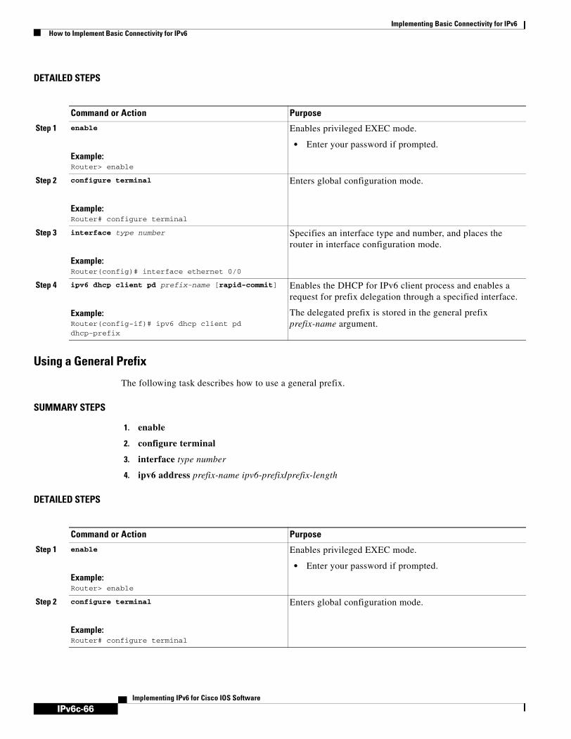
IPv6c-66
Implementing Basic Connectivity for IPv6How to Implement Basic Connectivity for IPv6
Implementing IPv6 for Cisco IOS Software
DETAILED STEPS
Using a General Prefix
The following task describes how to use a general prefix.
SUMMARY STEPS
1. enable
2. configure terminal
3. interface type number
4. ipv6 address prefix-name ipv6-prefix/prefix-length
DETAILED STEPS
Command or Action Purpose
Step 1 enable
Example:Router> enable
Enables privileged EXEC mode.
• Enter your password if prompted.
Step 2 configure terminal
Example:Router# configure terminal
Enters global configuration mode.
Step 3 interface type number
Example:Router(config)# interface ethernet 0/0
Specifies an interface type and number, and places the router in interface configuration mode.
Step 4 ipv6 dhcp client pd prefix-name [rapid-commit]
Example:Router(config-if)# ipv6 dhcp client pd dhcp-prefix
Enables the DHCP for IPv6 client process and enables a request for prefix delegation through a specified interface.
The delegated prefix is stored in the general prefix prefix-name argument.
Command or Action Purpose
Step 1 enable
Example:Router> enable
Enables privileged EXEC mode.
• Enter your password if prompted.
Step 2 configure terminal
Example:Router# configure terminal
Enters global configuration mode.

IPv6c-67
Implementing Basic Connectivity for IPv6How to Implement Basic Connectivity for IPv6
Implementing IPv6 for Cisco IOS Software
Configuring IPv4 and IPv6 Protocol StacksWhen an interface in a Cisco networking device is configured with both an IPv4 and an IPv6 address, the interface forwards both IPv4 and IPv6 traffic—the interface can send and receive data on both IPv4 and IPv6 networks. To configure an interface in a Cisco networking device to support both the IPv4 and IPv6 protocol stacks, use the following commands beginning in global configuration mode:
SUMMARY STEPS
1. enable
2. configure terminal
3. ipv6 unicast-routing
4. interface type number
5. ip address ip-address mask [secondary]
6. ipv6 address ipv6-prefix/prefix-length [eui-64]
DETAILED STEPS
Step 3 interface type number
Example:Router(config)# interface ethernet 0/0
Specifies an interface type and number, and places the router in interface configuration mode.
Step 4 ipv6 address prefix-name ipv6-prefix/prefix-length
Example:Router(config-if) ipv6 address my-prefix 2001:0DB8:0:7272::/64
Configures an IPv6 prefix name for an IPv6 address and enables IPv6 processing on the interface.
Command or Action Purpose
Command Purpose
Step 1 enable
Example:Router> enable
Enables privileged EXEC mode.
• Enter your password if prompted.
Step 2 configure terminal
Example:Router# configure terminal
Enters global configuration mode.
Step 3 ipv6 unicast-routing
Example:Router(config)# ipv6 unicast routing
Enables the forwarding of IPv6 unicast datagrams.

IPv6c-68
Implementing Basic Connectivity for IPv6How to Implement Basic Connectivity for IPv6
Implementing IPv6 for Cisco IOS Software
Configuring Syslog over IPv6
This task explains how to configure syslog over IPv6.
SUMMARY STEPS
1. enable
2. configure terminal
3. logging host {ip-address | ipv6 ipv6-address | hostname} [transport {udp [port port-number] | tcp [port port-number] [audit]}] [xml | filtered [stream stream-id]]
Step 4 interface type number
Example:Router(config)# interface ethernet 0
Specifies the interface type and number, and enters interface configuration mode.
Step 5 ip address ip-address mask [secondary]
Example:Router(config-if)# ip address 192.168.99.1 255.255.255.0
Specifies a primary or secondary IPv4 address for an interface.
Refer to the “Configuring IP Addressing” chapter of Cisco IOS IP Configuration Guide, Release 12.4, for information on configuring IPv4 addresses.
Step 6 ipv6 address ipv6-prefix/prefix-length [eui-64]
Example:Router(config-if)# ipv6 address 2001:0DB8:c18:1::3/64
Specifies the IPv6 network assigned to the interface and enables IPv6 processing on the interface.
Note See the “Configuring IPv6 Addressing and Enabling IPv6 Routing” section for more information on configuring IPv6 addresses.
Command Purpose

IPv6c-69
Implementing Basic Connectivity for IPv6How to Implement Basic Connectivity for IPv6
Implementing IPv6 for Cisco IOS Software
DETAILED STEPS
Configuring IPv6 ICMP Rate LimitingThis task explains how to configure the interval and and bucket size for IPv6 ICMP error messages.
IPv6 ICMP Rate Limiting
In Cisco IOS Release 12.2(8)T or later releases, the IPv6 ICMP rate limiting feature implements a token bucket algorithm for limiting the rate at which IPv6 ICMP error messages are sent out on the network. The initial implementation of IPv6 ICMP rate limiting defined a fixed interval between error messages, but some applications, such as traceroute, often require replies to a group of requests sent in rapid succession. The fixed interval between error messages is not flexible enough to work with applications such as traceroute and can cause the application to fail. Implementing a token bucket scheme allows a number of tokens—representing the ability to send one error message each—to be stored in a virtual bucket. The maximum number of tokens allowed in the bucket can be specified, and for every error message to be sent, one token is removed from the bucket. If a series of error messages is generated, error messages can be sent until the bucket is empty. When the bucket is empty of tokens, IPv6 ICMP error messages are not sent until a new token is placed in the bucket. The token bucket algorithm does not increase the average rate limiting time interval, and it is more flexible than the fixed time interval scheme.
SUMMARY STEPS
1. enable
2. configure terminal
3. ipv6 icmp error-interval milliseconds [bucketsize]
Command Purpose
Step 1 enable
Example:Router> enable
Enables privileged EXEC mode.
• Enter your password if prompted.
Step 2 configure terminal
Example:Router# configure terminal
Enters global configuration mode.
Step 3 logging host {ip-address | ipv6 ipv6-address | hostname} [transport {udp [port port-number] | tcp [port port-number] [audit]}] [xml | filtered [stream stream-id]]
Example:Router(config)# logging host ipv6 AAAA:BBBB:CCCC:DDDD::FFFF
Logs system messages and debug output to a remote host.
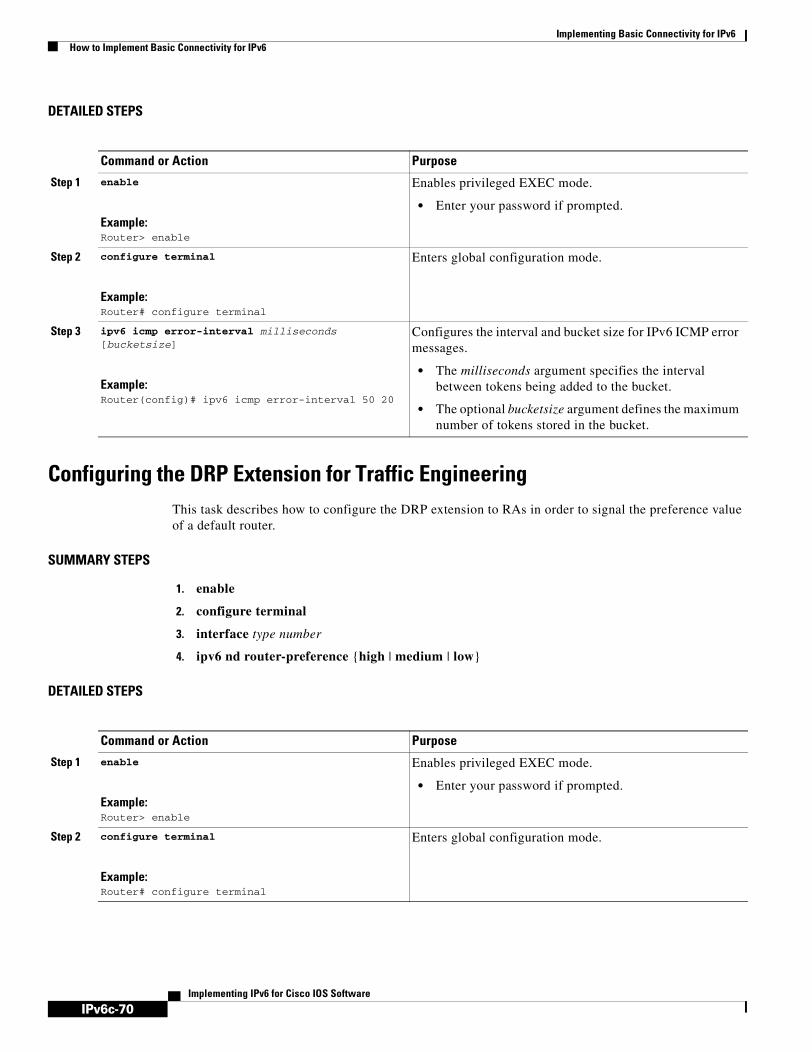
IPv6c-70
Implementing Basic Connectivity for IPv6How to Implement Basic Connectivity for IPv6
Implementing IPv6 for Cisco IOS Software
DETAILED STEPS
Configuring the DRP Extension for Traffic Engineering This task describes how to configure the DRP extension to RAs in order to signal the preference value of a default router.
SUMMARY STEPS
1. enable
2. configure terminal
3. interface type number
4. ipv6 nd router-preference {high | medium | low}
DETAILED STEPS
Command or Action Purpose
Step 1 enable
Example:Router> enable
Enables privileged EXEC mode.
• Enter your password if prompted.
Step 2 configure terminal
Example:Router# configure terminal
Enters global configuration mode.
Step 3 ipv6 icmp error-interval milliseconds [bucketsize]
Example:Router(config)# ipv6 icmp error-interval 50 20
Configures the interval and bucket size for IPv6 ICMP error messages.
• The milliseconds argument specifies the interval between tokens being added to the bucket.
• The optional bucketsize argument defines the maximum number of tokens stored in the bucket.
Command or Action Purpose
Step 1 enable
Example:Router> enable
Enables privileged EXEC mode.
• Enter your password if prompted.
Step 2 configure terminal
Example:Router# configure terminal
Enters global configuration mode.

IPv6c-71
Implementing Basic Connectivity for IPv6How to Implement Basic Connectivity for IPv6
Implementing IPv6 for Cisco IOS Software
Configuring CEF and dCEF Switching for IPv6This task explains how to configure CEFv6 and dCEFv6. By default, CEFv6 and dCEFv6 are disabled.
CEF Switching on Distributed and Nondistributed Architecture Platforms
CEFv6 is designed for nondistributed architecture platforms, such as the Cisco 7200 series routers. dCEFv6 is designed for distributed architecture platforms, such as the Cisco 12000 series Internet routers or the Cisco 7500 series routers. Nondistributed platforms do not support dCEFv6; however, some distributed platforms, such as the Cisco 7500 series routers, support both CEFv6 and dCEFv6. When CEFv6 is configured on Cisco 7500 series routers, CEF switching is performed by the RP; when dCEFv6 is configured, CEF switching is performed by the line cards. By default, the Cisco 12000 series Internet routers support only dCEFv6 (CEF switching is performed by the line cards).
Prerequisites
To forward CEFv6 and dCEFv6 traffic, you must configure the forwarding of IPv6 unicast datagrams globally on the router by using the ipv6 unicast-routing global configuration command, and you must configure an IPv6 address and IPv6 processing on an interface by using the ipv6 address interface configuration command.
You must enable CEFv4 globally on the router by using the ip cef command in global configuration mode before enabling CEFv6 globally on the router.
You must enable dCEFv4 by using the ip cef distributed command in global configuration mode before enabling dCEFv6.
Restrictions
The ipv6 cef and ipv6 cef distributed commands are not supported on the Cisco 12000 series Internet routers because this distributed platform operates only in dCEFv6 mode.
• In Cisco IOS Release 12.0(22)S or later releases, the following restrictions apply to nondistributed and distributed architecture platforms configured for CEFv6 and dCEFv6:
Note By default, the Cisco 12000 series Internet routers support only dCEFv6 (CEF switching is performed by the line cards).
Step 3 interface type number
Example:Router(config)# interface ethernet 0
Specifies the interface type and number, and enters interface configuration mode.
Step 4 ipv6 nd router-preference {high | medium | low}
Example:Router(config-if)# ipv6 nd router-preference
high
Configures a DRP for a router on a specific interface
Command or Action Purpose

IPv6c-72
Implementing Basic Connectivity for IPv6How to Implement Basic Connectivity for IPv6
Implementing IPv6 for Cisco IOS Software
– IPv6 packets that have global or site-local source and destination addresses are CEFv6-switched or dCEFv6-switched.
– IPv6 packets that have link-local source and destination addresses are process-switched.
– IPv6 packets that are tunneled within manually configured IPv6 tunnels are CEFv6-switched.
Note dCEFv6-switching of IPv6 packets that are tunneled within manually configured IPv6 tunnels is planned for a later release of the Cisco IOS software.
– Only the following interface and encapsulation types are supported:
ATM PVC and ATM LANE
Cisco High-Level Data Link Control
Ethernet, Fast Ethernet, and Gigabit Ethernet
FDDI
Frame Relay PVC
PPP over Packet-Over-SONET, ISDN, and serial (synchronous and asynchronous) interface types
– The following interface and encapsulation types are not supported:
HP 100VG-AnyLAN
Switched Multimegabit Data Service (SMDS)
Token Ring
X.25
Note Contact your local Cisco Systems account representative for specific CEFv6 and dCEFv6 hardware restrictions.
SUMMARY STEPS
1. enable
2. configure terminal
3. ipv6 ceforipv6 cef distributed
4. ipv6 cef accounting [non-recursive | per-prefix | prefix-length]

IPv6c-73
Implementing Basic Connectivity for IPv6How to Implement Basic Connectivity for IPv6
Implementing IPv6 for Cisco IOS Software
DETAILED STEPS
Configuring Unicast RPF
This task explains how to associate host names with IPv6 addresses.
Command or Action Purpose
Step 1 enable
Example:Router> enable
Enables privileged EXEC mode.
• Enter your password if prompted.
Step 2 configure terminal
Example:Router# configure terminal
Enters global configuration mode.
Step 3 ipv6 cef
or
ipv6 cef distributed
Example:Router(config)# ipv6 cef
or
Example:Router(config)# ipv6 cef distributed
Enables CEFv6 globally on the router.
or
Enables dCEFv6 globally on the router.
Step 4 ipv6 cef accounting [non-recursive | per-prefix | prefix-length]
Example:Router(config)# ipv6 cef accounting
Enables CEFv6 and dCEFv6 network accounting globally on the router.
• Network accounting for CEFv6 and dCEFv6 enables you to better understand CEFv6 traffic patterns within your network by collecting statistics specific to CEFv6 and dCEFv6 traffic. For example, network accounting for CEFv6 and dCEFv6 enables you to collect information such as the number of packets and bytes switched to a destination or the number of packets switched through a destination.
• The optional per-prefix keyword enables the collection of the number of packets and bytes express forwarded to an IPv6 destination (or IPv6 prefix).
• The optional prefix-length keyword enables the collection of the number of packets and bytes express forwarded to an IPv6 prefix length.
Note When CEFv6 is enabled globally on the router, accounting information is collected at the RP; when dCEFv6 is enabled globally on the router, accounting information is collected at the line cards.

IPv6c-74
Implementing Basic Connectivity for IPv6How to Implement Basic Connectivity for IPv6
Implementing IPv6 for Cisco IOS Software
Prerequisites
To use Unicast RPF, enable CEF switching or dCEF switching in the router. There is no need to configure the input interface for CEF switching. As long as CEF is running on the router, individual interfaces can be configured with other switching modes.
Note It is very important for CEF to be configured globally in the router. Unicast RPF will not work without CEF.
Restrictions
Unicast RPF should not be used on interfaces that are internal to the network. Internal interfaces are likely to have routing asymmetry, meaning that there are multiple routes to the source of a packet. Unicast RPF should be applied only where there is natural or configured symmetry.
For example, routers at the edge of the network of an Internet service provider (ISP) are more likely to have symmetrical reverse paths than routers that are in the core of the ISP network. Routers that are in the core of the ISP network have no guarantee that the best forwarding path out of the router will be the path selected for packets returning to the router. Therefore, we do not recommend that you apply Unicast RPF where there is a chance of asymmetric routing. It is simplest to place Unicast RPF only at the edge of a network or, for an ISP, at the customer edge of the network.
SUMMARY STEPS
1. enable
2. configure terminal
3. interface type number
4. ipv6 verify unicast source reachable-via {rx | any} [allow-default] [allow-self-ping] [list]
DETAILED STEPS
Command or Action Purpose
Step 1 enable
Example:Router> enable
Enables privileged EXEC mode.
• Enter your password if prompted.
Step 2 configure terminal
Example:Router# configure terminal
Enters global configuration mode.

IPv6c-75
Implementing Basic Connectivity for IPv6How to Implement Basic Connectivity for IPv6
Implementing IPv6 for Cisco IOS Software
Configuring NetFlow in IPv6 EnvironmentsTo configure NetFlow, you must define the exporting scheme that will be used to export NetFlow statistics, configure the NetFlow cache, and configure NetFlow on the interfaces from which statistics will be gathered. The tasks required to complete perform these functions are described in the following sections:
• Exporting NetFlow Statistics, page 75
• Configuring and Customizing the NetFlow Cache, page 77
• Managing NetFlow Statistics, page 78
• Configuring an Aggregation Cache, page 79
• Configuring a NetFlow Minimum Prefix Mask for Router-Based Aggregation, page 81
Exporting NetFlow StatisticsThis task describes how to define the exporting scheme that will be used to gather NetFlow statistics.
SUMMARY STEPS
1. enable
2. configure terminal
3. ipv6 flow-export version 9 [bgp-nexthop] [origin-as [bgp-nexthop] | peer-as [bgp-nexthop]]
4. ipv6 flow-aggregation cache {as | bgp-nexthop | destination-prefix | prefix | protocol-port | source-prefix}
5. enabled
6. ipv6 flow-export template {refresh-rate packet-refresh-rate | timeout timeout-value}
Step 3 interface type number
Example:Router(config)# interface atm 0
Specifies an interface type and number, and places the router in interface configuration mode.
Step 4 ipv6 verify unicast source reachable-via {rx | any} [allow-default] [allow-self-ping] [list]
Example:Router(config-if)# ipv6 verify unicast source reachable-via any
Verifies that a source address exists in the FIB table and enables Unicast RPF.
Command or Action Purpose

IPv6c-76
Implementing Basic Connectivity for IPv6How to Implement Basic Connectivity for IPv6
Implementing IPv6 for Cisco IOS Software
DETAILED STEPS
Command or Action Purpose
Step 1 enable
Example:Router> enable
Enables privileged EXEC mode.
• Enter your password if prompted.
Step 2 configure terminal
Example:Router# configure terminal
Enters global configuration mode.
Step 3 Router(config-if)# ipv6 flow-export version 9 [bgp-nexthop] [origin-as [bgp-nexthop] | peer-as [bgp-nexthop]]
Example:Router(config-if)# ipv6 flow-export version 9 bgp-nexthop
Enables NetFlow for IPv6 routing.
The example shows how to collect the next BGP hop.
Step 4 ipv6 flow-export destination ip-address udp-port
Example:Router(config-if)# ipv6 flow-export destination 10.0.101.254 9991
Configures the router to export NetFlow cache entries to a workstation.
Step 5 Router(config-flow-cache)# ipv6 flow-export template {refresh-rate packet-refresh-rate | timeout timeout-value}
Example:Router(config-flow-cache)# ipv6 flow-export template timeout 60
Enables the exporting of information in NetFlow cache entries.
Sets the timeout rate to 60 minutes.
Step 6 Router(config-flow-cache)# ipv6 flow-export template {refresh-rate packet-refresh-rate | timeout timeout-value}
Example:Router(config-flow-cache)# ipv6 flow-export template refresh-rate 30
Sets the refresh rate to 30 packets.

IPv6c-77
Implementing Basic Connectivity for IPv6How to Implement Basic Connectivity for IPv6
Implementing IPv6 for Cisco IOS Software
Configuring and Customizing the NetFlow CacheSeveral options are available for configuring and customizing the NetFlow cache.
• Customize the number of entries in the NetFlow cache
• Customize the timeout.
• Customize the MPLS parameters.
These options are all optional and are described in the following section:
• Customizing the NetFlow Cache, page 77
Customizing the NetFlow Cache
Normally the size of the NetFlow cache will meet your needs. However, you can increase or decrease the number of entries maintained in the cache to meet the needs of your NetFlow traffic rates. The default is 64K flow cache entries. Each cache entry requires about 64 bytes of storage. Assuming a cache with the default number of entries, about 4 MB of DRAM would be required. Each time a new flow is taken from the free flow queue, the number of free flows is checked. If only a few free flows remain, NetFlow attempts to age 30 flows using an accelerated timeout. If only one free flow remains, NetFlow automatically ages 30 flows regardless of their age. The intent is to ensure that free flow entries are always available.
Caution Cisco recommends that you not change the number of NetFlow cache entries. Improper use of this feature could cause network problems. To return to the default NetFlow cache entries, use the no ip flow-cache entries global configuration command.
The following task describes how to customize the number of entries in the NetFlow cache.
SUMMARY STEPS
1. enable
Step 7 Router(config-flow-cache)# ipv6 flow-export template options {export-stats | refresh-rate packet-refresh-rate | timeout}
Example:Router(config-flow-cache)# ipv6 flow-export
template options export-stats
Configures option templates.
Export statistics reports how many export packets have been sent and how many flows are exported.
Step 8 Router(config-flow-cache)# ipv6 flow {ingress | egress}
Example:Router(config-flow-cache)# ipv6 flow ingress
(Optional) Enables IPv6 flow capture for incoming (ingress) or outgoing (egress) packets.
Two commands for ingress and egress can be specified on the same interface. If a switched packet belongs to a flow that is captured at both ingress and egress, it will be accounted twice.This command must be entered on each interface where NetFlow capture is needed.
Command or Action Purpose

IPv6c-78
Implementing Basic Connectivity for IPv6How to Implement Basic Connectivity for IPv6
Implementing IPv6 for Cisco IOS Software
2. configure terminal
1. ipv6 flow-cache entries number
2. ipv6 flow-cache timeout {active minutes | inactive seconds}
3. ipv6 flow-aggregation cache {as | bgp-nexthop | destination-prefix | prefix | protocol-port | source-prefix}
DETAILED STEPS
Managing NetFlow StatisticsYou can display and clear NetFlow statistics. NetFlow statistics consist of IP packet size distribution, IP flow cache information, and flow information such as the protocol, total flow, flows per second, and so on. The resulting information can be used to determine information about your router traffic.
The following task describes how to manage NetFlow statistics. Use these commands as needed for verification of configuration.
Command or Action Purpose
Step 1 enable
Example:Router> enable
Enables privileged EXEC mode.
• Enter your password if prompted.
Step 2 configure terminal
Example:Router# configure terminal
Enters global configuration mode.
Step 3 ipv6 flow-cache entries number
Example:Router(config)# ipv6 flow-cache entries number
Changes the number of entries maintained in the NetFlow cache. The number of entries can be from 1024 to 524288. The default is 65536.
Step 4 ipv6 flow-cache timeout {active minutes | inactive seconds}
Example:Router(config)# ipv6 flow-cache timeout active 10
Customizes the cache timeout parameters.
Step 5 ipv6 flow-aggregation cache {as | bgp-nexthop |destination-prefix | prefix | protocol-port | source-prefix}
Example:Router(config)# ipv6 flow-aggregation cache mpls
Customizes the cache MPLS parameters.

IPv6c-79
Implementing Basic Connectivity for IPv6How to Implement Basic Connectivity for IPv6
Implementing IPv6 for Cisco IOS Software
SUMMARY STEPS
1. enable
1. show ip cache flow
2. clear ip flow stats
DETAILED STEPS
Configuring an Aggregation CacheTo configure an aggregation cache, you must enter aggregation cache configuration mode, and you must decide which type of aggregation scheme you would like to configure: Autonomous System, Destination Prefix, Prefix, Protocol Prefix, or Source Prefix aggregation cache. Once you define the aggregation scheme, the following task lets you define the operational parameters for that scheme.
SUMMARY STEPS
1. enable
2. configure terminal
3. ipv6 flow-export destination ip-address udp-port
4. ipv6 flow-aggregation cache {as | bgp-nexthop | destination-prefix | prefix | protocol-port | source-prefix}
5. cache {entries number | timeout {active minutes | inactive seconds}}
6. cache {entries number | timeout {active minutes | inactive seconds}}
7. ipv6 flow-export destination ip-address udp-port
Command or Action Purpose
Step 1 enable
Example:Router> enable
Enables privileged EXEC mode.
• Enter your password if prompted.
Step 2 show ip cache flow
Example:Router# show ip cache flow
Displays the NetFlow statistics.
Step 3 clear ip flow stats
Example:Router# clear ip flow stats
Clears the NetFlow statistics.

IPv6c-80
Implementing Basic Connectivity for IPv6How to Implement Basic Connectivity for IPv6
Implementing IPv6 for Cisco IOS Software
8. enabled
Command Purpose
Step 1 enable
Example:Router> enable
Enables privileged EXEC mode.
• Enter your password if prompted.
Step 2 configure terminal
Example:Router# configure terminal
Enters global configuration mode.
Step 3 ipv6 flow-export destination ip-address udp-port
Example:Router# ipv6 flow-export destination 10.0.101.254 9991
Enables the exporting of information in NetFlow cache entries to a specific address or port.
Step 4 ipv6 flow-aggregation cache {as | bgp-nexthop | destination-prefix | prefix | protocol-port | source-prefix}
Example:Router(config)# ipv6 flow-aggregation cache as
Enters aggregation cache configuration mode and enables an aggregation cache scheme (as, destination-prefix, prefix, protocol-port, or source-prefix).
Step 5 cache {entries number | timeout {active minutes | inactive seconds}}
Example:Router(config-flow-cache)# cache entries 2046
Specifies the number (in this example, 2046) of cache entries to allocate for the Autonomous System aggregation cache.
Step 6 cache {entries number | timeout {active minutes | inactive seconds}}
Example:Router(config-flow-cache)# cache timeout inactive 199
Specifies the number of seconds (in this example, 199) that an inactive entry is allowed to remain in the aggregation cache before it is deleted.
Step 7 cache {entries number | timeout {active minutes | inactive seconds}}
Example:Router(config-flow-cache)# cache timeout active 45
Specifies the number of minutes (in this example, 45) that an active entry is active.
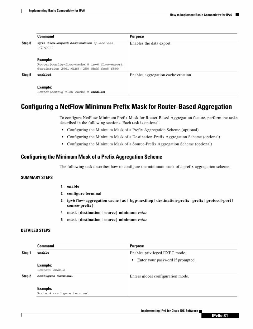
IPv6c-81
Implementing Basic Connectivity for IPv6How to Implement Basic Connectivity for IPv6
Implementing IPv6 for Cisco IOS Software
Configuring a NetFlow Minimum Prefix Mask for Router-Based AggregationTo configure NetFlow Minimum Prefix Mask for Router-Based Aggregation feature, perform the tasks described in the following sections. Each task is optional.
• Configuring the Minimum Mask of a Prefix Aggregation Scheme (optional)
• Configuring the Minimum Mask of a Destination-Prefix Aggregation Scheme (optional)
• Configuring the Minimum Mask of a Source-Prefix Aggregation Scheme (optional)
Configuring the Minimum Mask of a Prefix Aggregation Scheme
The following task describes how to configure the minimum mask of a prefix aggregation scheme.
SUMMARY STEPS
1. enable
2. configure terminal
3. ipv6 flow-aggregation cache {as | bgp-nexthop | destination-prefix | prefix | protocol-port | source-prefix}
4. mask {destination | source} minimum value
5. mask {destination | source} minimum value
DETAILED STEPS
Step 8 ipv6 flow-export destination ip-address udp-port
Example:Router(config-flow-cache)# ipv6 flow-export destination 2001:0DB8::250:8bff:fee8:f800
Enables the data export.
Step 9 enabled
Example:Router(config-flow-cache)# enabled
Enables aggregation cache creation.
Command Purpose
Command Purpose
Step 1 enable
Example:Router> enable
Enables privileged EXEC mode.
• Enter your password if prompted.
Step 2 configure terminal
Example:Router# configure terminal
Enters global configuration mode.

IPv6c-82
Implementing Basic Connectivity for IPv6How to Implement Basic Connectivity for IPv6
Implementing IPv6 for Cisco IOS Software
Configuring the Minimum Mask of a Destination-Prefix Aggregation Scheme
The following task describes how to configure the minimum mask of a destination-prefix aggregation scheme.
SUMMARY STEPS
1. enable
2. configure terminal
3. ipv6 flow-aggregation cache {as | bgp-nexthop | destination-prefix | prefix | protocol-port | source-prefix}
4. mask {destination | source} minimum value
DETAILED STEPS
Step 3 ipv6 flow-aggregation cache {as | bgp-nexthop | destination-prefix | prefix | protocol-port | source-prefix}
Example:Router(config)# ipv6 flow-aggregation cache prefix
Configures the prefix aggregation cache.
Step 4 mask {destination | source} minimum value
Example:Router(config-flow-cache)# mask source minimum value
Specifies the minimum value for the source mask.
Step 5 mask {destination | source} minimum value
Example:Router(config-flow-cache)# mask destination minimum value
Specifies minimum value for the destination mask.
Command Purpose
Command Purpose
Step 1 enable
Example:Router> enable
Enables privileged EXEC mode.
• Enter your password if prompted.
Step 2 configure terminal
Example:Router# configure terminal
Enters global configuration mode.

IPv6c-83
Implementing Basic Connectivity for IPv6How to Implement Basic Connectivity for IPv6
Implementing IPv6 for Cisco IOS Software
Configuring the Minimum Mask of a Source-Prefix Aggregation Scheme
The following task describes how to configure the minimum mask of a source-prefix aggregation scheme.
Note If the minimum mask has not been explicitly configured, no minimum mask information is displayed. The default value of the minimum mask is zero. The configurable range for the minimum mask is from 1 to 32. An appropriate value should be chosen by the user depending on the traffic. A higher value of the minimum mask will provide more detailed network addresses, but it may also result in increased number of flows in the aggregation cache.
SUMMARY STEPS
1. enable
2. configure terminal
3. ipv6 flow-aggregation cache {as | bgp-nexthop | destination-prefix | prefix | protocol-port | source-prefix}
4. mask {destination | source} minimum value
DETAILED STEPS
Step 3 ipv6 flow-aggregation cache {as | bgp-nexthop | destination-prefix | prefix | protocol-port | source-prefix}
Example:Router(config)# ipv6 flow-aggregation cache destination-prefix
Configures the destination aggregation cache.
Step 4 mask {destination | source} minimum value
Example:Router(config-flow-cache)# mask destination minimum 32
Specifies the minimum value for the destination mask.
Command Purpose
Command Purpose
Step 1 enable
Example:Router> enable
Enables privileged EXEC mode.
• Enter your password if prompted.
Step 2 configure terminal
Example:Router# configure terminal
Enters global configuration mode.
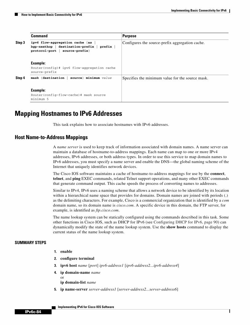
IPv6c-84
Implementing Basic Connectivity for IPv6How to Implement Basic Connectivity for IPv6
Implementing IPv6 for Cisco IOS Software
Mapping Hostnames to IPv6 AddressesThis task explains how to associate hostnames with IPv6 addresses.
Host Name-to-Address Mappings
A name server is used to keep track of information associated with domain names. A name server can maintain a database of hostname-to-address mappings. Each name can map to one or more IPv4 addresses, IPv6 addresses, or both address types. In order to use this service to map domain names to IPv6 addresses, you must specify a name server and enable the DNS—the global naming scheme of the Internet that uniquely identifies network devices.
The Cisco IOS software maintains a cache of hostname-to-address mappings for use by the connect, telnet, and ping EXEC commands, related Telnet support operations, and many other EXEC commands that generate command output. This cache speeds the process of converting names to addresses.
Similar to IPv4, IPv6 uses a naming scheme that allows a network device to be identified by its location within a hierarchical name space that provides for domains. Domain names are joined with periods (.) as the delimiting characters. For example, Cisco is a commercial organization that is identified by a com domain name, so its domain name is cisco.com. A specific device in this domain, the FTP server, for example, is identified as ftp.cisco.com.
The name lookup system can be statically configured using the commands described in this task. Some other functions in Cisco IOS, such as DHCP for IPv6 (see Configuring DHCP for IPv6, page 90) can dynamically modify the state of the name lookup system. Use the show hosts command to display the current status of the name lookup system.
SUMMARY STEPS
1. enable
2. configure terminal
3. ipv6 host name [port] ipv6-address1 [ipv6-address2...ipv6-address4]
4. ip domain-name nameorip domain-list name
5. ip name-server server-address1 [server-address2...server-address6]
Step 3 ipv6 flow-aggregation cache {as | bgp-nexthop | destination-prefix | prefix | protocol-port | source-prefix}
Example:Router(config)# ipv6 flow-aggregation cache source-prefix
Configures the source-prefix aggregation cache.
Step 4 mask {destination | source} minimum value
Example:Router(config-flow-cache)# mask source minimum 5
Specifies the minimum value for the source mask.
Command Purpose

IPv6c-85
Implementing Basic Connectivity for IPv6How to Implement Basic Connectivity for IPv6
Implementing IPv6 for Cisco IOS Software
6. ip domain-lookup
DETAILED STEPS
Command or Action Purpose
Step 1 enable
Example:Router> enable
Enables privileged EXEC mode.
• Enter your password if prompted.
Step 2 configure terminal
Example:Router# configure terminal
Enters global configuration mode.
Step 3 ipv6 host name [port] ipv6-address1 [ipv6-address2...ipv6-address4]
Example:Router(config)# ipv6 host cisco-sj 2001:0DB8:20:1::12
Defines a static hostname-to-address mapping in the hostname cache.
• Typically, it is easier to refer to network devices by symbolic names rather than numerical addresses (services such as Telnet can use hostnames or addresses). Hostnames and IPv6 addresses can be associated with one another through static or dynamic means.
• Manually assigning hostnames to addresses is useful when dynamic mapping is not available.
Step 4 ip domain-name name
or
ip domain-list name
Example:Router(config)# ip domain-name cisco.com
or
Example:Router(config)# ip domain-list cisco1.com
(Optional) Defines a default domain name that the Cisco IOS software will use to complete unqualified hostnames.
or
(Optional) Defines a list of default domain names to complete unqualified hostnames.
• You can specify a default domain name that the Cisco IOS software will use to complete domain name requests. You can specify either a single domain name or a list of domain names. Any hostname that does not contain a complete domain name will have the default domain name you specify appended to it before the name is looked up.
Note The ip domain-name and ip domain-list commands are used to specify default domain names that can be used by both IPv4 and IPv6.

IPv6c-86
Implementing Basic Connectivity for IPv6How to Implement Basic Connectivity for IPv6
Implementing IPv6 for Cisco IOS Software
Configuring IPv6 ATM and Frame Relay Interfaces This section explains how to how to map IPv6 addresses to ATM and Frame Relay permanent virtual circuits (PVCs). Specifically, the steps in this section explain how to explicitly map IPv6 addresses to the ATM and Frame Relay PVCs used to reach the addresses.
Note This task shows how to configure both ATM and Frame Relay PVCs and many of the steps are labeled optional because many networks will require only one type of PVC to be configured. The steps in this section are not applicable to ATM LAN Emulation (LANE).
IPv6 for Cisco IOS Software Support for Wide-Area Networking Technologies
IPv6 for Cisco IOS software supports wide-area networking technologies such as Cisco High-Level Data Link Control (HDLC), PPP over Packet Over SONET (PoS), ISDN, and serial (synchronous and asynchronous) interface types, ATM PVCs, and Frame Relay PVCs. These technologies function the same in IPv6 as they do in IPv4—IPv6 does not enhance the technologies in any way. However, new commands for mapping protocol (network-layer) addresses to ATM and Frame Relay PVCs have been introduced for IPv6.
IPv6 Addresses and PVCs
Broadcast and multicast are used in LANs to map protocol (network-layer) addresses to the hardware addresses of remote nodes (hosts and routers). Because using broadcast and multicast to map network-layer addresses to hardware addresses in circuit-based WANs such as ATM and Frame Relay networks is difficult to implement, these networks utilize implicit, explicit, and dynamic mappings for the network-layer addresses of remote nodes and the PVCs used to reach the addresses.
Assigning an IPv6 address to an interface by using the ipv6 address interface configuration command defines the IPv6 addresses for the interface and the network that is directly connected to the interface. If only one PVC is terminated on the interface (the interface is a point-to-point interface), there is an implicit mapping between all of the IPv6 addresses on the network and the PVC used to reach the addresses (no additional address mappings are needed). If several PVCs are terminated on the interface (the interface is a point-to-multipoint interface), the protocol ipv6 ATM VC configuration command (for ATM networks) or the frame-relay map ipv6 interface configuration command (for Frame Relay networks) is used to configure explicit mappings between the IPv6 addresses of the remote nodes and the PVCs used to reach the addresses.
Step 5 ip name-server server-address1 [server-address2...server-address6]
Example:Router(config)# ip name-server 2001:0DB8::250:8bff:fee8:f800 2001:0DB8:0:f004::1
Specifies one or more hosts that supply name information.
• Specifies one or more hosts (up to six) that can function as a name server to supply name information for DNS.
Note The server-address argument can be either an IPv4 or IPv6 address.
Step 6 ip domain-lookup
Example:Router(config)# ip domain-lookup
Enables DNS-based address translation.
• DNS is enabled by default.
Command or Action Purpose
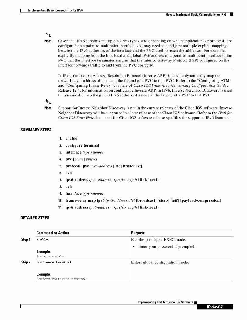
IPv6c-87
Implementing Basic Connectivity for IPv6How to Implement Basic Connectivity for IPv6
Implementing IPv6 for Cisco IOS Software
Note Given that IPv6 supports multiple address types, and depending on which applications or protocols are configured on a point-to-multipoint interface, you may need to configure multiple explicit mappings between the IPv6 addresses of the interface and the PVC used to reach the addresses. For example, explicitly mapping both the link-local and global IPv6 address of a point-to-multipoint interface to the PVC that the interface terminates ensures that the Interior Gateway Protocol (IGP) configured on the interface forwards traffic to and from the PVC correctly.
In IPv4, the Inverse Address Resolution Protocol (Inverse ARP) is used to dynamically map the network-layer address of a node at the far end of a PVC to that PVC. Refer to the “Configuring ATM” and “Configuring Frame Relay” chapters of Cisco IOS Wide-Area Networking Configuration Guide, Release 12.4, for information on configuring Inverse ARP. In IPv6, Inverse Neighbor Discovery is used to dynamically map the global IPv6 address of a node at the far end of a PVC to that PVC.
Note Support for Inverse Neighbor Discovery is not in the current releases of the Cisco IOS software. Inverse Neighbor Discovery will be supported in a later release of the Cisco IOS software. Refer to the IPv6 for Cisco IOS Start Here document for Cisco IOS software release specifics for supported IPv6 features.
SUMMARY STEPS
1. enable
2. configure terminal
3. interface type number
4. pvc [name] vpi/vci
5. protocol ipv6 ipv6-address [[no] broadcast]]
6. exit
7. ipv6 address ipv6-address {/prefix-length | link-local}
8. exit
9. interface type number
10. frame-relay map ipv6 ipv6-address dlci [broadcast] [cisco] [ietf] [payload-compression]
11. ipv6 address ipv6-address {/prefix-length | link-local}
DETAILED STEPS
Command or Action Purpose
Step 1 enable
Example:Router> enable
Enables privileged EXEC mode.
• Enter your password if prompted.
Step 2 configure terminal
Example:Router# configure terminal
Enters global configuration mode.
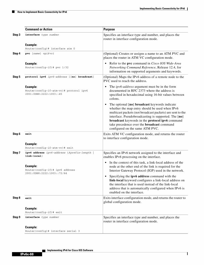
IPv6c-88
Implementing Basic Connectivity for IPv6How to Implement Basic Connectivity for IPv6
Implementing IPv6 for Cisco IOS Software
Step 3 interface type number
Example:Router(config)# interface atm 0
Specifies an interface type and number, and places the router in interface configuration mode.
Step 4 pvc [name] vpi/vci
Example:Router(config-if)# pvc 1/32
(Optional) Creates or assigns a name to an ATM PVC and places the router in ATM VC configuration mode.
• Refer to the pvc command in Cisco IOS Wide-Area Networking Command Reference, Release 12.4, for information on supported arguments and keywords.
Step 5 protocol ipv6 ipv6-address [[no] broadcast]
Example:Router(config-if-atm-vc)# protocol ipv6 2001:0DB8:2222:1003::45
(Optional) Maps the IPv6 address of a remote node to the PVC used to reach the address.
• The ipv6-address argument must be in the form documented in RFC 2373 where the address is specified in hexadecimal using 16-bit values between colons.
• The optional [no] broadcast keywords indicate whether the map entry should be used when IPv6 multicast packets (not broadcast packets) are sent to the interface. Pseudobroadcasting is supported. The [no] broadcast keywords in the protocol ipv6 command take precedence over the broadcast command configured on the same ATM PVC.
Step 6 exit
Example:Router(config-if-atm-vc)# exit
Exits ATM VC configuration mode, and returns the router to interface configuration mode.
Step 7 ipv6 address ipv6-address {/prefix-length | link-local}
Example:Router(config-if)# ipv6 address 2001:0DB8:2222:1003::72/64
Specifies an IPv6 network assigned to the interface and enables IPv6 processing on the interface.
• In the context of this task, a link-local address of the node at the other end of the link is required for the Interior Gateway Protocol (IGP) used in the network.
• Specifying the ipv6 address command with the link-local keyword configures a link-local address on the interface that is used instead of the link-local address that is automatically configured when IPv6 is enabled on the interface.
Step 8 exit
Example:Router(config-if)# exit
Exits interface configuration mode, and returns the router to global configuration mode.
Step 9 interface type number
Example:Router(config)# interface serial 3
Specifies an interface type and number, and places the router in interface configuration mode.
Command or Action Purpose

IPv6c-89
Implementing Basic Connectivity for IPv6How to Implement Basic Connectivity for IPv6
Implementing IPv6 for Cisco IOS Software
Step 10 frame-relay map ipv6 ipv6-address dlci [broadcast] [cisco] [ietf] [payload-compression]
Example:Router(config-if)# frame-relay map ipv6 FE80::E0:F727:E400:A 17 broadcast
(Optional) Maps the IPv6 address of a remote node to the data-link connection identifier (DLCI) of the PVC used to reach the address.
• The ipv6-address argument must be in the form documented in RFC 2373 where the address is specified in hexadecimal using 16-bit values between colons.
• The dlci argument specifies the DLCI number used to reach the specified IPv6 address on the interface. The acceptable range is from 16 to 1007.
• The optional broadcast keyword specifies that IPv6 multicast packets (not broadcast packets) should be forwarded to this IPv6 address when multicast is not enabled. (Refer to the frame-relay multicast-dlci command in the “Frame Relay Commands” chapter of Cisco IOS Wide-Area Networking Command Reference, Release 12.4, for information on defining a multicast DLCI.)
• The optional cisco keyword specifies the Cisco form of Frame Relay encapsulation.
• The optional ietf keyword specifies the IETF form of Frame Relay encapsulation.
• The optional payload-compression keyword specifies payload compression. (Refer to the frame-relay map ipv6 command in the IPv6 for Cisco IOS Command Reference document for subordinate keywords and arguments related to the payload-compression keyword.)
Step 11 ipv6 address ipv6-address {/prefix-length | link-local}
Example:Router(config-if)# ipv6 address 2001:0DB8:2222:1044::46/64
Specifies an IPv6 network assigned to the interface and enables IPv6 processing on the interface.
• In the context of this task, a link-local address of the node at the other end of the link is required for the IGP used in the network.
• Specifying the ipv6 address command with the link-local keyword configures a link-local address on the interface that is used instead of the link-local address that is automatically configured when IPv6 is enabled on the interface.
Command or Action Purpose

IPv6c-90
Implementing Basic Connectivity for IPv6How to Implement Basic Connectivity for IPv6
Implementing IPv6 for Cisco IOS Software
Configuring DHCP for IPv6The following tasks explain how to configure DHCP for IPv6:
• Configuring the DHCP for IPv6 Server Function, page 90
• Configuring the DHCP for IPv6 Client Function, page 91
• Configuring DHCP for IPv6 Relay Agent, page 92
• Configuring a Database Agent for the Server Function, page 93
• Configuring the Stateless DHCP for IPv6 Function, page 94
• Restarting the DHCP for IPv6 Client on an Interface, page 97
• Deleting Automatic Client Bindings from the DHCP for IPv6 Binding Table, page 97
• Troubleshooting DHCP for IPv6, page 98
Configuring the DHCP for IPv6 Server Function
This task explains how to create and configure the DHCP for IPv6 configuration pool and associate the pool with a server on an interface.
SUMMARY STEPS
1. enable
2. configure terminal
3. ipv6 dhcp pool poolname
4. domain-name domain
5. dns-server ipv6-address
6. prefix-delegation ipv6-prefix/prefix-length client-DUID [iaid iaid] [lifetime]
7. prefix-delegation pool poolname [lifetime]
8. exit
9. interface type number
10. ipv6 dhcp server poolname [rapid-commit] [preference value] [allow-hint]
DETAILED STEPS
Command or Action Purpose
Step 1 enable
Example:Router> enable
Enables privileged EXEC mode.
• Enter your password if prompted.
Step 2 configure terminal
Example:Router# configure terminal
Enters global configuration mode.

IPv6c-91
Implementing Basic Connectivity for IPv6How to Implement Basic Connectivity for IPv6
Implementing IPv6 for Cisco IOS Software
Configuring the DHCP for IPv6 Client Function
This task shows how to configure the DHCP for IPv6 client function on an interface and enable prefix delegation on an interface.
Step 3 ipv6 dhcp pool poolname
Example:Router(config)# ipv6 dhcp pool pool1
Configures a DHCP for IPv6 configuration information pool and enters DHCP for IPv6 pool configuration mode.
Step 4 domain-name domain
Example:Router(config-dhcp)# domain-name domain1.com
Configures a domain name for a DHCP for IPv6 client.
Step 5 dns-server ipv6-address
Example:Router(config-dhcp)# dns-server 2001:0DB8:3000:3000::42
Specifies the DNS IPv6 servers available to a DHCP for IPv6 client.
Step 6 prefix-delegation ipv6-prefix/prefix-length client-DUID [iaid iaid] [lifetime]
Example:Router(config-dhcp)# prefix-delegation 2001:0DB8:1263::/48 0005000400F1A4D070D03
Specifies a manually configured numeric prefix to be delegated to a specified client’s IAPD.
Step 7 prefix-delegation pool poolname [lifetime]
Example:Router(config-dhcp)# prefix-delegation pool prefix-pool lifetime 1800 600
Specifies a named IPv6 local prefix pool from which prefixes are delegated to DHCP for IPv6 clients.
Step 8 exit
Example:Router(config-if)# exit
Exits DHCP for IPv6 pool configuration mode configuration mode, and returns the router to global configuration mode.
Step 9 interface type number
Example:Router(config)# interface serial 3
Specifies an interface type and number, and places the router in interface configuration mode.
Step 10 ipv6 dhcp server poolname [rapid-commit] [preference value] [allow-hint]
Example:Router(config-if)# ipv6 dhcp server dhcp-pool
Enables DHCP for IPv6 on an interface.
Command or Action Purpose

IPv6c-92
Implementing Basic Connectivity for IPv6How to Implement Basic Connectivity for IPv6
Implementing IPv6 for Cisco IOS Software
SUMMARY STEPS
1. enable
2. configure terminal
3. interface type number
4. ipv6 dhcp client pd prefix-name [rapid-commit]
DETAILED STEPS
Configuring DHCP for IPv6 Relay Agent
This task describes how to enable the DHCP for IPv6 relay agent function and specify relay destination addresses on an interface.
SUMMARY STEPS
1. enable
2. configure terminal
3. interface type number
4. ipv6 dhcp relay destination ipv6-address [interface-type interface-number]
Command or Action Purpose
Step 1 enable
Example:Router> enable
Enables privileged EXEC mode.
• Enter your password if prompted.
Step 2 configure terminal
Example:Router# configure terminal
Enters global configuration mode.
Step 3 interface type number
Example:Router(config)# interface ethernet 0/0
Specifies an interface type and number, and places the router in interface configuration mode.
Step 4 ipv6 dhcp client pd prefix-name [rapid-commit]
Example:Router(config-if)# ipv6 dhcp client pd dhcp-prefix
Enables the DHCP for IPv6 client process and enables a request for prefix delegation through a specified interface.

IPv6c-93
Implementing Basic Connectivity for IPv6How to Implement Basic Connectivity for IPv6
Implementing IPv6 for Cisco IOS Software
DETAILED STEPS
Configuring a Database Agent for the Server Function
This task shows how to configure a DHCP for IPv6 binding database agent for the server function.
SUMMARY STEPS
1. enable
2. configure terminal
3. ipv6 dhcp database agent-URL [write-delay seconds] [timeout seconds]
Command or Action Purpose
Step 1 enable
Example:Router> enable
Enables privileged EXEC mode.
• Enter your password if prompted.
Step 2 configure terminal
Example:Router# configure terminal
Enters global configuration mode.
Step 3 interface type number
Example:Router(config)# interface ethernet4/2
Specifies an interface type and number, and places the router in interface configuration mode.
Step 4 ipv6 dhcp relay destination ipv6-address [interface-type interface-number]
Example:Router(config-if) ipv6 dhcp relay destination FE80::250:A2FF:FEBF:A056 ethernet4/3
Specifies a destination address to which client messages are forwarded and enables DHCP for IPv6 relay service on the interface.

IPv6c-94
Implementing Basic Connectivity for IPv6How to Implement Basic Connectivity for IPv6
Implementing IPv6 for Cisco IOS Software
DETAILED STEPS
Configuring the Stateless DHCP for IPv6 Function
The following tasks describe how to use the DHCP for IPv6 function to configure clients with information about the name lookup system. The server maintains no state related to clients; for example, no prefix pools and records of allocation are maintained. Therefore, this function is “stateless” DHCP for IPv6.
Configuring the Stateless DHCP for IPv6 Server
The following task describes how to configure the stateless DHCP for IPv6 server.
SUMMARY STEPS
1. enable
2. configure terminal
3. ipv6 dhcp pool poolname
4. dns-server ipv6-address
5. domain-name domain
6. exit
7. interface type number
8. ipv6 dhcp server poolname [rapid-commit] [preference value] [allow-hint]
9. ipv6 nd other-config-flag
Command or Action Purpose
Step 1 enable
Example:Router> enable
Enables privileged EXEC mode.
• Enter your password if prompted.
Step 2 configure terminal
Example:Router# configure terminal
Enters global configuration mode.
Step 3 ipv6 dhcp database agent-URL [write-delay seconds] [timeout seconds]
Example:Router(config)# ipv6 dhcp database tftp://10.0.0.1/dhcp-binding
Specifies DHCP for IPv6 binding database agent parameters.
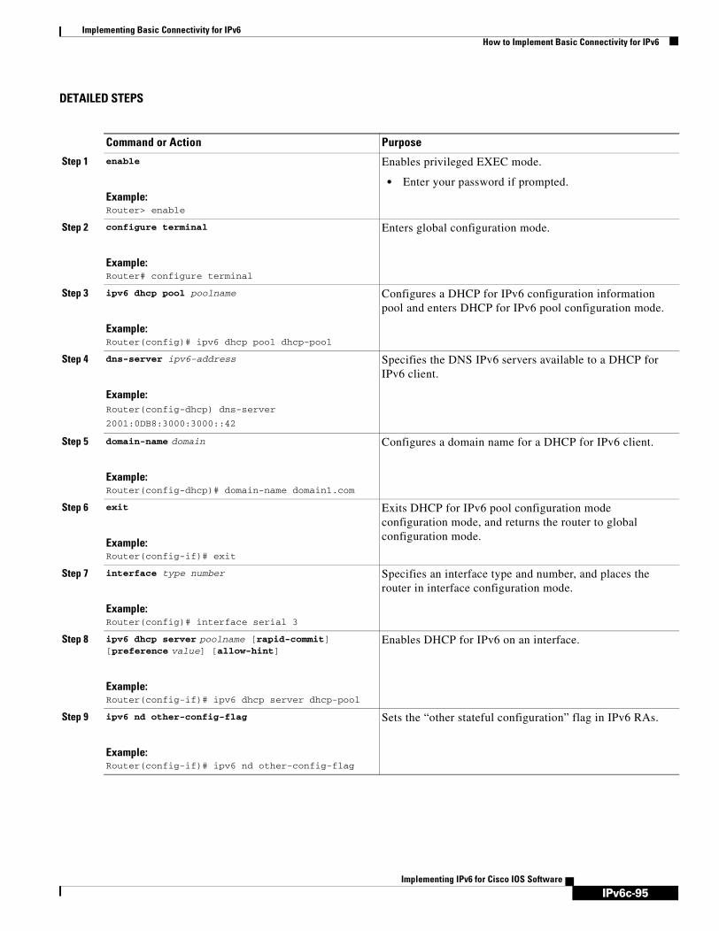
IPv6c-95
Implementing Basic Connectivity for IPv6How to Implement Basic Connectivity for IPv6
Implementing IPv6 for Cisco IOS Software
DETAILED STEPS
Command or Action Purpose
Step 1 enable
Example:Router> enable
Enables privileged EXEC mode.
• Enter your password if prompted.
Step 2 configure terminal
Example:Router# configure terminal
Enters global configuration mode.
Step 3 ipv6 dhcp pool poolname
Example:Router(config)# ipv6 dhcp pool dhcp-pool
Configures a DHCP for IPv6 configuration information pool and enters DHCP for IPv6 pool configuration mode.
Step 4 dns-server ipv6-address
Example:Router(config-dhcp) dns-server
2001:0DB8:3000:3000::42
Specifies the DNS IPv6 servers available to a DHCP for IPv6 client.
Step 5 domain-name domain
Example:Router(config-dhcp)# domain-name domain1.com
Configures a domain name for a DHCP for IPv6 client.
Step 6 exit
Example:Router(config-if)# exit
Exits DHCP for IPv6 pool configuration mode configuration mode, and returns the router to global configuration mode.
Step 7 interface type number
Example:Router(config)# interface serial 3
Specifies an interface type and number, and places the router in interface configuration mode.
Step 8 ipv6 dhcp server poolname [rapid-commit] [preference value] [allow-hint]
Example:Router(config-if)# ipv6 dhcp server dhcp-pool
Enables DHCP for IPv6 on an interface.
Step 9 ipv6 nd other-config-flag
Example:Router(config-if)# ipv6 nd other-config-flag
Sets the “other stateful configuration” flag in IPv6 RAs.

IPv6c-96
Implementing Basic Connectivity for IPv6How to Implement Basic Connectivity for IPv6
Implementing IPv6 for Cisco IOS Software
Configuring the Stateless DHCP for IPv6 Client
The following task describes how to configure the stateless DHCP for IPv6 client.
SUMMARY STEPS
1. enable
2. configure terminal
3. interface type number
4. ipv6 address autoconfig
DETAILED STEPS
Enabling Processing of Packets with Source Routing Header Options
The following task describes how to enable the processing of packets with source routing header options.
SUMMARY STEPS
1. enable
2. configure terminal
3. ipv6 source-route
Command or Action Purpose
Step 1 enable
Example:Router> enable
Enables privileged EXEC mode.
• Enter your password if prompted.
Step 2 configure terminal
Example:Router# configure terminal
Enters global configuration mode.
Step 3 interface type number
Example:Router(config)# interface serial 3
Specifies an interface type and number, and places the router in interface configuration mode.
Step 4 ipv6 address autoconfig
Example:Router(config-if)# ipv6 address autoconfig
Enables automatic configuration of IPv6 addresses using stateless autoconfiguration on an interface and enables IPv6 processing on the interface.

IPv6c-97
Implementing Basic Connectivity for IPv6How to Implement Basic Connectivity for IPv6
Implementing IPv6 for Cisco IOS Software
DETAILED STEPS
Restarting the DHCP for IPv6 Client on an Interface
This task explains how to restart the DHCP for IPv6 client on a specified interface after first releasing and unconfiguring previously acquired prefixes and other configuration options.
SUMMARY STEPS
1. enable
2. clear ipv6 dhcp client interface-type interface-number
DETAILED STEPS
Deleting Automatic Client Bindings from the DHCP for IPv6 Binding Table
This task explains how to delete automatic client bindings from the DHCP for IPv6 binding table.
SUMMARY STEPS
1. enable
Command or Action Purpose
Step 1 enable
Example:Router> enable
Enables privileged EXEC mode.
• Enter your password if prompted.
Step 2 configure terminal
Example:Router# configure terminal
Enters global configuration mode.
Step 3 ipv6 source-route
Example:Router(config)# ipv6 source-route
Enable processing of the IPv6 type 0 routing header.
Command or Action Purpose
Step 1 enable
Example:Router> enable
Enables privileged EXEC mode.
• Enter your password if prompted.
Step 2 clear ipv6 dhcp client interface-type interface-number
Example:Router# clear ipv6 dhcp client Ethernet 1/0
Restarts DHCP for IPv6 client on an interface.
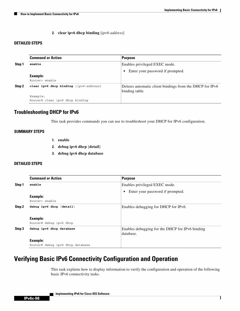
IPv6c-98
Implementing Basic Connectivity for IPv6How to Implement Basic Connectivity for IPv6
Implementing IPv6 for Cisco IOS Software
2. clear ipv6 dhcp binding [ipv6-address]
DETAILED STEPS
Troubleshooting DHCP for IPv6
This task provides commands you can use to troubleshoot your DHCP for IPv6 configuration.
SUMMARY STEPS
1. enable
2. debug ipv6 dhcp [detail]
3. debug ipv6 dhcp database
DETAILED STEPS
Verifying Basic IPv6 Connectivity Configuration and OperationThis task explains how to display information to verify the configuration and operation of the following basic IPv6 connectivity tasks.
Command or Action Purpose
Step 1 enable
Example:Router> enable
Enables privileged EXEC mode.
• Enter your password if prompted.
Step 2 clear ipv6 dhcp binding [ipv6-address]
Example:Router# clear ipv6 dhcp binding
Deletes automatic client bindings from the DHCP for IPv6 binding table.
Command or Action Purpose
Step 1 enable
Example:Router> enable
Enables privileged EXEC mode.
• Enter your password if prompted.
Step 2 debug ipv6 dhcp [detail]
Example:Router# debug ipv6 dhcp
Enables debugging for DHCP for IPv6.
Step 3 debug ipv6 dhcp database
Example:Router# debug ipv6 dhcp database
Enables debugging for the DHCP for IPv6 binding database.

IPv6c-99
Implementing Basic Connectivity for IPv6How to Implement Basic Connectivity for IPv6
Implementing IPv6 for Cisco IOS Software
• IPv6 Redirect Messages, page 99
IPv6 Redirect Messages
The IPv6 Redirect Messages feature enables a router to send Internet Control Message Protocol (ICMP) IPv6 neighbor redirect messages to inform hosts of better first hop nodes (routers or hosts) on the path to a destination.
There are no configuration tasks for the IPv6 Redirect Messages feature. The sending of IPv6 redirect messages is enabled by default. Use the no ipv6 redirects command in interface configuration mode to disable the sending of IPv6 redirect messages on an interface. Use the ipv6 redirects command in interface configuration mode to reenable the sending of IPv6 redirect messages if the Cisco IOS software is forced to resend a packet through the same interface on which the packet was received.
To verify whether the sending of IPv6 redirect messages is enabled on an interface, enter the show ipv6 interface command.
SUMMARY STEPS
1. enable
2. show ipv6 interface [brief] [[interface-type interface-number] [prefix]]
3. show ipv6 neighbors [interface-type interface-number | ipv6-address]
4. show ipv6 route [ipv6-address | ipv6-prefix/prefix-length | protocol]
5. show ipv6 traffic
6. show frame-relay map
7. show atm map
8. show ipv6 dhcp
9. show ipv6 dhcp binding [client-address]
10. show ipv6 dhcp database [agent-URL]
11. show ipv6 dhcp interface [interface-type interface-number]
12. show ipv6 dhcp pool [poolname]
13. show hosts
14. enable
15. show running-config

IPv6c-100
Implementing Basic Connectivity for IPv6How to Implement Basic Connectivity for IPv6
Implementing IPv6 for Cisco IOS Software
DETAILED STEPS
Command or Action Purpose
Step 1 enable
Example:Router# enable
Enables privileged EXEC mode.
• Enter your password if prompted.
Step 2 show ipv6 interface [brief] [[interface-type interface-number] [prefix]]
Example:Router# show ipv6 interface ethernet 0
Displays the usability status of interfaces configured for IPv6.
• Displays information about the status of IPv6 neighbor redirect messages, IPv6 neighbor discovery messages, and stateless autoconfiguration.
Step 3 show ipv6 neighbors [interface-type interface-number | ipv6-address]
Example:Router# show ipv6 neighbors ethernet 2
Displays IPv6 neighbor discovery cache information.
Step 4 show ipv6 route [ipv6-address | ipv6-prefix/prefix-length | protocol]
Example:Router# show ipv6 route
(Optional) Displays the current contents of the IPv6 routing table.
Step 5 show ipv6 traffic
Example:Router# show ipv6 traffic
(Optional) Displays statistics about IPv6 traffic.
Step 6 show frame-relay map
Example:Router# show frame-relay map
Displays the current map entries and information about the Frame Relay connections.
Step 7 show atm map
Example:Router# show atm map
Displays the list of all configured ATM static maps to remote hosts on an ATM network and on ATM bundle maps.
Step 8 show ipv6 dhcp
Example:Router# show ipv6 dhcp
Displays the DHCP unique identifier DUID on a specified device.
Step 9 show ipv6 dhcp binding [ipv6-address]
Example:Router# show ipv6 dhcp binding
Displays automatic client bindings from the DHCP for IPv6 database.
Step 10 show ipv6 dhcp database [agent-URL]
Example:Router# show ipv6 dhcp database
Displays the DHCP for IPv6 binding database agent information.

IPv6c-101
Implementing Basic Connectivity for IPv6How to Implement Basic Connectivity for IPv6
Implementing IPv6 for Cisco IOS Software
Examples
This section provides the following output examples:
• Sample Output for the show ipv6 interfaces Command
• Sample Output for the show ipv6 neighbors Command
• Sample Output for the show ipv6 route Command
• Sample Output for the show ipv6 traffic Command
• Sample Output for the show frame-relay map Command
• Sample Output for the show atm map Command
• Sample Output for the show ipv6 dhcp Command
• Sample Output for the show ipv6 dhcp binding Command
• Sample Output for the show ipv6 dhcp database Command
• Sample Output for the show ipv6 dhcp interface Command
• Sample Output for the show ipv6 dhcp pool Command
• Sample Output for the show running-config Command
• Sample Output for the show hosts Command
Step 11 show ipv6 dhcp interface [interface-type interface-number]
Example:Router# show ipv6 dhcp interface
Displays DHCP for IPv6 interface information.
Step 12 show ipv6 dhcp pool [poolname]
Example:Router# show ipv6 dhcp pool
Displays DHCP for IPv6 configuration pool information.
Step 13 show hosts
Example:Router# show hosts
Displays the default domain name, the style of name lookup service, a list of name server hosts, and the cached list of host names and addresses.
Step 14 enable
Example:Router> enable
Enables privileged EXEC mode.
• Enter your password if prompted.
Step 15 show running-config
Example:Router# show running-config
Displays the current configuration running on the router.
Command or Action Purpose

IPv6c-102
Implementing Basic Connectivity for IPv6How to Implement Basic Connectivity for IPv6
Implementing IPv6 for Cisco IOS Software
Sample Output for the show ipv6 interfaces Command
In the following example, the show ipv6 interface user EXEC command is used to verify that IPv6 addresses are configured correctly for Ethernet interface 0. Information is also displayed about the status of IPv6 neighbor redirect messages, IPv6 neighbor discovery messages and stateless autoconfiguration.
Router# show ipv6 interface ethernet 0
Ethernet0 is up, line protocol is up IPv6 is stalled, link-local address is FE80::1 Global unicast address(es): 2001:0DB8:2000::1, subnet is 2001:0DB8:2000::/64 2001:0DB8:3000::1, subnet is 2001:0DB8:3000::/64 Joined group address(es): FF02::1 FF02::2 FF02::1:FF00:1 MTU is 1500 bytes ICMP error messages limited to one every 100 milliseconds ICMP redirects are enabled ND DAD is enabled, number of DAD attempts: 1 ND reachable time is 30000 milliseconds ND advertised reachable time is 0 milliseconds ND advertised retransmit interval is 0 milliseconds ND router advertisements are sent every 200 seconds ND router advertisements live for 1800 seconds Hosts use stateless autoconfig for addresses.
Note For a description of each output display field, refer to the show ipv6 interfaces command in the IPv6 for Cisco IOS Command Reference.
Sample Output for the show ipv6 neighbors Command
In the following example, the show ipv6 neighbors user EXEC command is used to display IPv6 neighbor discovery cache information. A hyphen (-) in the Age field of the command output indicates a static entry. The following example displays IPv6 neighbor discovery cache information for Ethernet interface 2:
Router# show ipv6 neighbors ethernet 2
IPv6 Address Age Link-layer Addr State Interface2001:0DB8:0:4::2 0 0003.a0d6.141e REACH Ethernet2FE80::XXXX:A0FF:FED6:141E 0 0003.a0d6.141e REACH Ethernet22001:0DB8:1::45a - 0002.7d1a.9472 REACH Ethernet2
Note For a description of each output display field, refer to the show ipv6 neighbors command in the IPv6 for Cisco IOS Command Reference.

IPv6c-103
Implementing Basic Connectivity for IPv6How to Implement Basic Connectivity for IPv6
Implementing IPv6 for Cisco IOS Software
Sample Output for the show ipv6 route Command
When the ipv6-address or ipv6-prefix/prefix-length argument is specified, only route information for that address or network is displayed. The following is sample output from the show ipv6 route user EXEC command when entered with the IPv6 prefix 2001:0DB8::/35:
Router# show ipv6 route 2001:0DB8::/35
IPv6 Routing Table - 261 entriesCodes: C - Connected, L - Local, S - Static, R - RIP, B - BGPI1 - ISIS L1, I2 - ISIS L2, IA - ISIS interarea
B 2001:0DB8::/35 [20/3] via FE80::60:5C59:9E00:16, Tunnel1
Note For a description of each output display field, refer to the show ipv6 route command in the IPv6 for Cisco IOS Command Reference.
Sample Output for the show ipv6 traffic Command
In the following example, the show ipv6 traffic user EXEC command is used to display ICMP rate-limited counters:
Router# show ipv6 traffic
ICMP statistics: Rcvd: 188 input, 0 checksum errors, 0 too short 0 unknown info type, 0 unknown error type unreach: 0 routing, 0 admin, 0 neighbor, 0 address, 0 port parameter: 0 error, 0 header, 0 option 0 hopcount expired, 0 reassembly timeout,0 too big 0 echo request, 0 echo reply 0 group query, 0 group report, 0 group reduce 1 router solicit, 175 router advert, 0 redirects 0 neighbor solicit, 12 neighbor advert Sent: 7376 output, 56 rate-limited unreach: 0 routing, 15 admin, 0 neighbor, 0 address, 0 port parameter: 0 error, 0 header, 0 option 0 hopcount expired, 0 reassembly timeout,0 too big 15 echo request, 0 echo reply 0 group query, 0 group report, 0 group reduce 0 router solicit, 7326 router advert, 0 redirects 2 neighbor solicit, 22 neighbor advert
Note For a description of each output display field, refer to the show ipv6 traffic command in the IPv6 for Cisco IOS Command Reference.
Sample Output for the show frame-relay map Command
In the following example, the show frame-relay map user EXEC command is used to verify that the IPv6 address of a remote node is mapped to the DLCI of the PVC used to reach the address. The following example shows that the link-local and global IPv6 addresses (FE80::E0:F727:E400:A and 2001:0DB8:2222:1044::73; FE80::60:3E47:AC8:8 and 2001.0DB8:2222:1044::72) of two remote nodes are explicitly mapped to DLCI 17 and DLCI 19, respectively. Both DLCI 17 and DLCI 19 are terminated on interface serial 3 of this node; therefore, interface serial 3 of this node is a point-to-multipoint interface.
Router# show frame-relay map
Serial3 (up): ipv6 FE80::E0:F727:E400:A dlci 17(0x11,0x410), static, broadcast, CISCO, status defined, active

IPv6c-104
Implementing Basic Connectivity for IPv6How to Implement Basic Connectivity for IPv6
Implementing IPv6 for Cisco IOS Software
Serial3 (up): ipv6 2001:0DB8:2222:1044::72 dlci 19(0x13,0x430), static, CISCO, status defined, active Serial3 (up): ipv6 2001:0DB8:2222:1044::73 dlci 17(0x11,0x410), static, CISCO, status defined, active Serial3 (up): ipv6 FE80::60:3E47:AC8:8 dlci 19(0x13,0x430), static, broadcast, CISCO, status defined, active
Sample Output for the show atm map Command
In the following example, the show atm map user EXEC command is used to verify that the IPv6 address of a remote node is mapped to the PVC used to reach the address. The following example shows that the link-local and global IPv6 addresses (FE80::60:3E47:AC8:C and 2001:0DB8:2222:1003::72, respectively) of a remote node are explicitly mapped to PVC 1/32 of ATM interface 0:
Router# show atm map
Map list ATM0pvc1 : PERMANENT ipv6 FE80::60:3E47:AC8:C maps to VC 1, VPI 1, VCI 32, ATM0 , broadcast ipv6 2001:0DB8:2222:1003::72 maps to VC 1, VPI 1, VCI 32, ATM0
Sample Output for the show ipv6 dhcp Command
The following example from the show ipv6 dhcp command shows the DUID of the device:
Router# show ipv6 dhcp
This device's DHCPv6 unique identifier(DUID): 000300010002FCA5DC1C
Sample Output for the show ipv6 dhcp binding Command
In the following example, the show ipv6 dhcp binding command shows information about two clients, including their DUIDs, IAPDs, prefixes, and preferred and valid lifetimes:
Router# show ipv6 dhcp binding
Client: FE80::202:FCFF:FEA5:DC39 (Ethernet2/1)DUID: 000300010002FCA5DC1CIA PD: IA ID 0x00040001, T1 0, T2 0
Prefix: 3FFE:C00:C18:11::/68preferred lifetime 180, valid lifetime 12345expires at Nov 08 2002 02:24 PM (12320 seconds)
Client: FE80::202:FCFF:FEA5:C039 (Ethernet2/1)DUID: 000300010002FCA5C01CIA PD: IA ID 0x00040001, T1 0, T2 0
Prefix: 3FFE:C00:C18:1::/72preferred lifetime 240, valid lifetime 54321expires at Nov 09 2002 02:02 AM (54246 seconds)
Prefix: 3FFE:C00:C18:2::/72preferred lifetime 300, valid lifetime 54333expires at Nov 09 2002 02:03 AM (54258 seconds)
Prefix: 3FFE:C00:C18:3::/72preferred lifetime 280, valid lifetime 51111
Sample Output for the show ipv6 dhcp database Command
In the following example, the show ipv6 dhcp database command provides information on the binding database agents TFTP, NVRAM, and Flash:
Router# show ipv6 dhcp database
Database agent tftp://172.19.216.133/db.tftp:write delay: 69 seconds, transfer timeout: 300 secondslast written at Jan 09 2003 01:54 PM,
write timer expires in 56 seconds

IPv6c-105
Implementing Basic Connectivity for IPv6How to Implement Basic Connectivity for IPv6
Implementing IPv6 for Cisco IOS Software
last read at Jan 06 2003 05:41 PMsuccessful read times 1failed read times 0successful write times 3172failed write times 2
Database agent nvram:/dhcpv6-binding:write delay: 60 seconds, transfer timeout: 300 secondslast written at Jan 09 2003 01:54 PM,
write timer expires in 37 secondslast read at neversuccessful read times 0failed read times 0successful write times 3325failed write times 0
Database agent flash:/dhcpv6-db:write delay: 82 seconds, transfer timeout: 3 secondslast written at Jan 09 2003 01:54 PM,
write timer expires in 50 secondslast read at neversuccessful read times 0failed read times 0successful write times 2220failed write times 614
Sample Output for the show ipv6 dhcp interface Command
The following is sample output from the show ipv6 dhcp interface command. In the first example, the command is used on a router that has an interface acting as a DHCP for IPv6 server. In the second example, the command is used on a router that has an interface acting as a DHCP for IPv6 client:
Router1# show ipv6 dhcp interface
Ethernet2/1 is in server modeUsing pool: svr-p1Preference value: 20Rapid-Commit is disabled
Router2# show ipv6 dhcp interface
Ethernet2/1 is in client modeState is OPEN (1)List of known servers:
Address: FE80::202:FCFF:FEA1:7439, DUID 000300010002FCA17400Preference: 20
IA PD: IA ID 0x00040001, T1 120, T2 192Prefix: 3FFE:C00:C18:1::/72
preferred lifetime 240, valid lifetime 54321expires at Nov 08 2002 09:10 AM (54319 seconds)
Prefix: 3FFE:C00:C18:2::/72preferred lifetime 300, valid lifetime 54333expires at Nov 08 2002 09:11 AM (54331 seconds)
Prefix: 3FFE:C00:C18:3::/72preferred lifetime 280, valid lifetime 51111expires at Nov 08 2002 08:17 AM (51109 seconds)
DNS server: 2001:0DB8:1001::1DNS server: 2001:0DB8:1001::2Domain name: domain1.netDomain name: domain2.netDomain name: domain3.net
Prefix name is cli-p1Rapid-Commit is enabled

IPv6c-106
Implementing Basic Connectivity for IPv6How to Implement Basic Connectivity for IPv6
Implementing IPv6 for Cisco IOS Software
Sample Output for the show ipv6 dhcp pool Command
In the following example, the show ipv6 dhcp pool command provides information on the configuration pool named svr-p1, including the static bindings, prefix information, the DNS server, and the domain names found in the svr-p1 pool:
Router# show ipv6 dhcp pool
DHCPv6 pool: svr-p1Static bindings:
Binding for client 000300010002FCA5C01CIA PD: IA ID 00040002,
Prefix: 3FFE:C00:C18:3::/72preferred lifetime 604800, valid lifetime 2592000
IA PD: IA ID not specified; being used by 00040001Prefix: 3FFE:C00:C18:1::/72
preferred lifetime 240, valid lifetime 54321Prefix: 3FFE:C00:C18:2::/72
preferred lifetime 300, valid lifetime 54333Prefix: 3FFE:C00:C18:3::/72
preferred lifetime 280, valid lifetime 51111Prefix from pool: local-p1, Valid lifetime 12345, Preferred lifetime 180DNS server: 2001:0DB8:1001::1DNS server: 2001:0DB8:1001::2Domain name: domain1.netDomain name: domain2.netDomain name: domain3.net
Active clients: 2
Sample Output for the show running-config Command
In the following example, the show running-config privileged EXEC command is used to verify that IPv6 processing of packets is enabled globally on the router and on applicable interfaces, and that an IPv6 address is configured on applicable interfaces:
Router# show running-config
Building configuration...
Current configuration : 22324 bytes!! Last configuration change at 14:59:38 PST Tue Jan 16 2001! NVRAM config last updated at 04:25:39 PST Tue Jan 16 2001 by bird!hostname Router!ipv6 unicast-routing!interface Ethernet0 no ip route-cache no ip mroute-cache no keepalive media-type 10BaseTipv6 address 2001:0DB8:0:1::/64 eui-64
!
Note Display text was omitted from the example.

IPv6c-107
Implementing Basic Connectivity for IPv6How to Implement Basic Connectivity for IPv6
Implementing IPv6 for Cisco IOS Software
In the following example, the show running-config privileged EXEC command is used to verify that CEFv6 and network accounting for CEFv6 have been enabled globally on a nondistributed architecture platform, and that CEFv6 has been enabled on an IPv6 interface. The following output shows that both that CEFv6 and network accounting for CEFv6 have been enabled globally on the router, and that CEFv6 has also been enabled on Ethernet interface 0:
Router# show running-config
Building configuration...
Current configuration : 22324 bytes ! ! Last configuration change at 14:59:38 PST Tue Jan 16 2001 ! NVRAM config last updated at 04:25:39 PST Tue Jan 16 2001 by bird ! hostname Router!ip cefipv6 unicast-routingipv6 cefipv6 cef accounting prefix-length!!interface Ethernet0 ip address 10.4.9.11 255.0.0.0 media-type 10BaseT ipv6 address 2001:0DB8:C18:1::/64 eui-64!
Note Display text was omitted from the output.
In the following example, the show running-config command in privileged EXEC mode is used to verify that dCEFv6 and network accounting for dCEFv6 have been enabled globally on a distributed architecture platform, such as the Cisco 7500 series routers. The following example shows that both dCEFv6 and network accounting for CEFv6 have been enabled globally on the router.
Note dCEFv6 is enabled by default on the Cisco 12000 series Internet routers and disabled by default on the Cisco 7500 series routers. Therefore, output from the show running-config privileged EXEC command on the Cisco 12000 series does not show whether dCEFv6 is configured globally on the router. The following output is from a Cisco 7500 series router.
Router# show running-config
Building configuration...
Current configuration : 22324 bytes!! Last configuration change at 14:59:38 PST Tue Jan 16 2001! NVRAM config last updated at 04:25:39 PST Tue Jan 16 2001 by bird!hostname Router!ip cef distributedipv6 unicast-routingipv6 cef distributedipv6 cef accounting prefix-length

IPv6c-108
Implementing Basic Connectivity for IPv6Configuration Examples for Implementing Basic Connectivity for IPv6
Implementing IPv6 for Cisco IOS Software
Note Display text was omitted from the output.
In the following example, the show running-config privileged EXEC command is used to verify static host name-to-address mappings, default domain names, and name servers in the host name cache, and to verify that the DNS service is enabled:
Router# show running-config
Building configuration...!ipv6 host cisco-sj 2001:0DB8:20:1::12!ip domain-name cisco.comip domain-lookupip name-server 2001:0DB8:C01F:768::1
Note Display text was omitted from the example.
Sample Output for the show hosts Command
The state of the name lookup system on the DHCP for IPv6 client can be displayed with the show hosts command.
Router# show hostsDefault domain is not setDomain list:verybigcompany.comName/address lookup uses domain serviceName servers are 2001:0DB8:A:B::1, 2001:0DB8:3000:3000::42
Codes:UN - unknown, EX - expired, OK - OK, ?? - revalidate temp - temporary, perm - permanent NA - Not Applicable None - Not defined
Host Port Flags Age Type Address(es)sdfasfd None (temp, UN) 0 IPv6
Configuration Examples for Implementing Basic Connectivity for IPv6
This section provides the following configuration examples:
• IPv6 Addressing and IPv6 Routing Configuration Example, page 109
• Dual Protocol Stacks Configuration Example, page 109
• IPv6 ICMP Rate Limiting Configuration: Example, page 110
• CEFv6 and dCEFv6 Configuration: Example, page 110
• Configuring NetFlow in IPv6 Environments: Example, page 110
• Host Name-to-Address Mappings Configuration: Example, page 111
• IPv6 Address to ATM and Frame Relay PVC Mapping Configuration Examples, page 111
• DHCP for IPv6 Configuration Examples, page 114
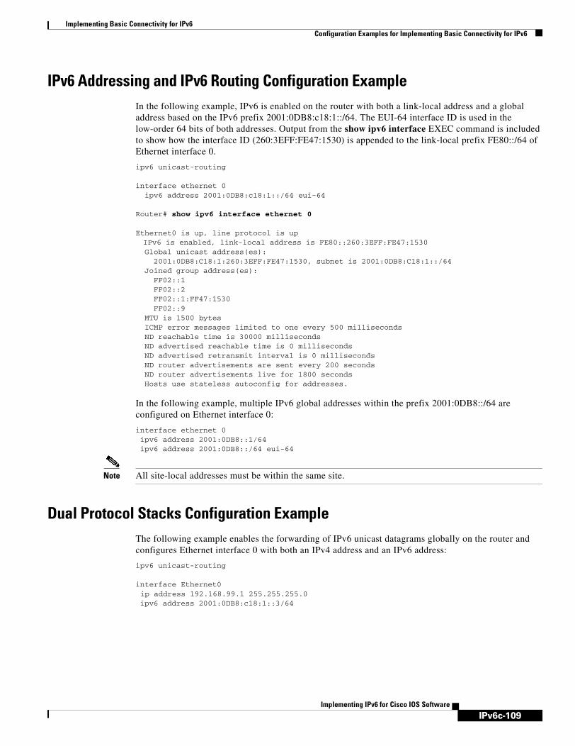
IPv6c-109
Implementing Basic Connectivity for IPv6Configuration Examples for Implementing Basic Connectivity for IPv6
Implementing IPv6 for Cisco IOS Software
IPv6 Addressing and IPv6 Routing Configuration ExampleIn the following example, IPv6 is enabled on the router with both a link-local address and a global address based on the IPv6 prefix 2001:0DB8:c18:1::/64. The EUI-64 interface ID is used in the low-order 64 bits of both addresses. Output from the show ipv6 interface EXEC command is included to show how the interface ID (260:3EFF:FE47:1530) is appended to the link-local prefix FE80::/64 of Ethernet interface 0.
ipv6 unicast-routing
interface ethernet 0ipv6 address 2001:0DB8:c18:1::/64 eui-64
Router# show ipv6 interface ethernet 0
Ethernet0 is up, line protocol is upIPv6 is enabled, link-local address is FE80::260:3EFF:FE47:1530
Global unicast address(es): 2001:0DB8:C18:1:260:3EFF:FE47:1530, subnet is 2001:0DB8:C18:1::/64 Joined group address(es): FF02::1 FF02::2 FF02::1:FF47:1530 FF02::9 MTU is 1500 bytes ICMP error messages limited to one every 500 milliseconds ND reachable time is 30000 milliseconds ND advertised reachable time is 0 milliseconds ND advertised retransmit interval is 0 milliseconds ND router advertisements are sent every 200 seconds ND router advertisements live for 1800 seconds Hosts use stateless autoconfig for addresses.
In the following example, multiple IPv6 global addresses within the prefix 2001:0DB8::/64 are configured on Ethernet interface 0:
interface ethernet 0ipv6 address 2001:0DB8::1/64
ipv6 address 2001:0DB8::/64 eui-64
Note All site-local addresses must be within the same site.
Dual Protocol Stacks Configuration ExampleThe following example enables the forwarding of IPv6 unicast datagrams globally on the router and configures Ethernet interface 0 with both an IPv4 address and an IPv6 address:
ipv6 unicast-routing
interface Ethernet0ip address 192.168.99.1 255.255.255.0ipv6 address 2001:0DB8:c18:1::3/64

IPv6c-110
Implementing Basic Connectivity for IPv6Configuration Examples for Implementing Basic Connectivity for IPv6
Implementing IPv6 for Cisco IOS Software
IPv6 ICMP Rate Limiting Configuration: ExampleThe following example shows an interval of 50 milliseconds and a bucket size of 20 tokens being configured for IPv6 ICMP error messages:
ipv6 icmp error-interval 50 20
CEFv6 and dCEFv6 Configuration: ExampleIn the following example, both CEFv6 and network accounting for CEFv6 have been enabled globally on a nondistributed architecture router, and CEFv6 has been enabled on Ethernet interface 0. The example also shows that the forwarding of IPv6 unicast datagrams has been configured globally on the router with the ipv6 unicast-routing command in global configuration mode, an IPv6 address has been configured on Ethernet interface 0 with the ipv6 address command in interface configuration mode, and CEFv4 has been configured globally on the router with the ip cef command in global configuration mode.
ip cefipv6 unicast-routingipv6 cefipv6 cef accounting prefix-length
interface Ethernet0 ip address 10.4.9.11 255.0.0.0 media-type 10BaseT ipv6 address 2001:0DB8:C18:1::/64 eui-64
In the following example, both dCEFv6 and network accounting for dCEFv6 have been enabled globally on a distributed architecture router. The forwarding of IPv6 unicast datagrams has been configured globally on the router with the ipv6 unicast-routing global configuration command and that dCEFv4 has been configured globally on the router with the ip cef distributed command in global configuration mode.
ip cef distributedipv6 unicast-routingipv6 cef distributedipv6 cef accounting prefix-length
Configuring NetFlow in IPv6 Environments: ExampleIf you configure the ipv6 flow ingress command on a few selected subinterfaces and then configure the ip route-cache flow command on the main interface, enabling the main interface will overwrite the ip flow ingress command and data collection will start from the main interface as well as all the subinterfaces. In a scenario where you configure the ipv6 flow ingress command and then configure the ip route-cache flow command on the main interface, you can restore subinterface data collection by using the no ip route-cache flow command. This configuration will disable data collection from the main interface and restore data collection to the subinterfaces you originally configured with the ipv6 flow ingress command.
The following example shows how to configure NetFlow on a Fast Ethernet subinterface 6/3.0:
Router(config)# interface FastEthernet6/3.0Router(config-subif)# ipv6 flow ingress

IPv6c-111
Implementing Basic Connectivity for IPv6Configuration Examples for Implementing Basic Connectivity for IPv6
Implementing IPv6 for Cisco IOS Software
The following example shows the configuration for a loopback source interface. The loopback interface has the IPv6 address 2001:0DB8:1:1:FFFF:FFFF:FFFF:FFFE/64 and is used by the serial interface in slot 5, port 0.
Router# configure terminalRouter(config)# interface loopback0Router(config-if)# ipv6 address 2001:0DB8:1:1:FFFF:FFFF:FFFF:FFFE/64Router(config-if)# exitRouter(config)# interface serial 5/0:0Router(config-if)# ip unnumbered loopback0Router(config-if)# encapsulation pppRouter(config-if)# ipv6 flow cacheRouter(config-if)# exitRouter(config)# ipv6 flow-export source loopback0Router(config)# exit
The following example shows a router configured to capture the first 64 bits of the source address for packets entering this interface:
Router(config)# interface FastEthernet6/3.0Router(config-subif)# ipv6 flow mask source maximum 64
Host Name-to-Address Mappings Configuration: Example The following example defines two static host name-to-address mappings in the host name cache, establishes a domain list with several alternate domain names to complete unqualified host names, specifies host 2001:0DB8::250:8bff:fee8:f800 and host 2001:0DB8:0:f004::1 as the name servers, and reenables the DNS service:
ipv6 host cisco-sj 2001:0DB8:700:20:1::12ipv6 host cisco-hq 2001:0DB8:768::1 2001:0DB8:20:1::22ip domain-list domain1-list.comip domain-list serviceprovider2-name.comip domain-list college2-name.eduip name-server 2001:0DB8::250:8bff:fee8:f800 2001:0DB8:0:f004::1ip domain-lookup
IPv6 Address to ATM and Frame Relay PVC Mapping Configuration Examples This section provides the following IPv6 ATM and Frame Relay PVC mapping configuration examples:
• IPv6 ATM PVC Mapping Configuration Example—Point-to-Point Interface
• IPv6 ATM PVC Mapping Configuration Example—Point-to-Multipoint Interface
• IPv6 Frame Relay PVC Mapping Configuration Example—Point-to-Point Interface
• IPv6 Frame Relay PVC Mapping Configuration Example—Point-to-Multipoint Interface
IPv6 ATM PVC Mapping Configuration Example—Point-to-Point Interface
In the following example, two nodes named Router 1 and Router 2 are connected by a single PVC. The point-to-point subinterface ATM0.132 is used on both nodes to terminate the PVC; therefore, the mapping between the IPv6 addresses of both nodes and the PVC is implicit (no additional mappings are required).
Router 1 Configurationinterface ATM0

IPv6c-112
Implementing Basic Connectivity for IPv6Configuration Examples for Implementing Basic Connectivity for IPv6
Implementing IPv6 for Cisco IOS Software
no ip address ! interface ATM0.132 point-to-point pvc 1/32 encapsulation aal5snap ! ipv6 address 2001:0DB8:2222:1003::72/64
Router 2 Configurationinterface ATM0 no ip address ! interface ATM0.132 point-to-point pvc 1/32 encapsulation aal5snap ! ipv6 address 2001:0DB8:2222:1003::45/64
IPv6 ATM PVC Mapping Configuration Example—Point-to-Multipoint Interface
In the following example, the same two nodes (Router 1 and Router 2) from the previous example are connected by the same PVC. In this example, however, the point-to-multipoint interface ATM0 is used on both nodes to terminate the PVC; therefore, explicit mappings are required between the link-local and global IPv6 addresses of interface ATM0 on both nodes and the PVC. Additionally, ATM pseudobroadcasts are enabled on the link-local address of interface ATM0 on both nodes. The link-local address specified here is the link-local address of the other end of the PVC.
Router 1 Configuration interface ATM0 no ip address pvc 1/32 protocol ipv6 2001:0DB8:2222:1003::45 protocol ipv6 FE80::60:2FA4:8291:2 broadcast encapsulation aal5snap ! ipv6 address 2001:0DB8:2222:1003::72/64
Router 2 Configurationinterface ATM0 no ip address pvc 1/32 protocol ipv6 FE80::60:3E47:AC8:C broadcast protocol ipv6 2001:0DB8:2222:1003::72 encapsulation aal5snap ! ipv6 address 2001:0DB8:2222:1003::45/64
IPv6 Frame Relay PVC Mapping Configuration Example—Point-to-Point Interface
In the following example, three nodes named Router A, Router B, and Router C make up a fully meshed network. Each node is configured with two PVCs, which provide an individual connection to each of the other two nodes. Each PVC is configured on a different point-to-point subinterface, which creates three unique IPv6 networks (2001:0DB8:2222:1017:/64, 2001:0DB8:2222:1018::/64, and 2001:0DB8:2222:1019::/64). Therefore, the mappings between the IPv6 addresses of each node and the DLCI (DLCI 17, 18, and 19) of the PVC used to reach the addresses are implicit (no additional mappings are required).

IPv6c-113
Implementing Basic Connectivity for IPv6Configuration Examples for Implementing Basic Connectivity for IPv6
Implementing IPv6 for Cisco IOS Software
Note Given that each PVC in the following example is configured on a different point-to-point subinterface, the configuration in the following example can also be used in a network that is not fully meshed. Additionally, configuring each PVC on a different point-to-point subinterface can help simplify your routing protocol configuration. However, the configuration in the following example requires more than one IPv6 network, whereas configuring each PVC on point-to-multipoint interfaces requires only one IPv6 network.
Router A Configurationinterface Serial3 encapsulation frame-relay ! interface Serial3.17 point-to-point description to Router B ipv6 address 2001:0DB8:2222:1017::46/64 frame-relay interface-dlci 17 ! interface Serial3.19 point-to-point description to Router C ipv6 address 2001:0DB8:2222:1019::46/64 frame-relay interface-dlci 19
Router B Configurationinterface Serial5 encapsulation frame-relay ! interface Serial5.17 point-to-point description to Router A ipv6 address 2001:0DB8:2222:1017::73/64 frame-relay interface-dlci 17 ! interface Serial5.18 point-to-point description to Router C ipv6 address 2001:0DB8:2222:1018::73/64 frame-relay interface-dlci 18
Router C Configurationinterface Serial0 encapsulation frame-relay ! interface Serial0.18 point-to-point description to Router B ipv6 address 2001:0DB8:2222:1018::72/64 frame-relay interface-dlci 18 ! interface Serial0.19 point-to-point description to Router A ipv6 address 2001:0DB8:2222:1019::72/64 frame-relay interface-dlci 19
IPv6 Frame Relay PVC Mapping Configuration Example—Point-to-Multipoint Interface In the following example, the same three nodes (Router A, Router B, and Router C) from the previous example make up a fully meshed network and each node is configured with two PVCs (which provide an individual connection to each of the other two nodes). However, the two PVCs on each node in the following example are configured on a single interface (serial 3, serial 5, and serial 10, respectively),

IPv6c-114
Implementing Basic Connectivity for IPv6Configuration Examples for Implementing Basic Connectivity for IPv6
Implementing IPv6 for Cisco IOS Software
which makes each interface a point-to-multipoint interface. Therefore, explicit mappings are required between the link-local and global IPv6 addresses of each interface on all three nodes and the DLCI (DLCI 17, 18, and 19) of the PVC used to reach the addresses.
Router A Configurationinterface Serial3 encapsulation frame-relay ipv6 address 2001:0DB8:2222:1044::46/64 frame-relay map ipv6 FE80::E0:F727:E400:A 17 broadcast frame-relay map ipv6 FE80::60:3E47:AC8:8 19 broadcast frame-relay map ipv6 2001:0DB8:2222:1044::72 19 frame-relay map ipv6 2001:0DB8:2222:1044::73 17
Router B Configurationinterface Serial5 encapsulation frame-relay ipv6 address 2001:0DB8:2222:1044::73/64 frame-relay map ipv6 FE80::60:3E59:DA78:C 17 broadcast frame-relay map ipv6 FE80::60:3E47:AC8:8 18 broadcast frame-relay map ipv6 2001:0DB8:2222:1044::46 17 frame-relay map ipv6 2001:0DB8:2222:1044::72 18
Router C Configurationinterface Serial10 encapsulation frame-relay ipv6 address 2001:0DB8:2222:1044::72/64 frame-relay map ipv6 FE80::60:3E59:DA78:C 19 broadcast frame-relay map ipv6 FE80::E0:F727:E400:A 18 broadcast frame-relay map ipv6 2001:0DB8:2222:1044::46 19 frame-relay map ipv6 2001:0DB8:2222:1044::73 18
DHCP for IPv6 Configuration ExamplesThis section provides the following DHCP for IPv6 mapping configuration examples:
• Configuring the DHCP for IPv6 Server Function: Example, page 114
• Configuring the DHCP for IPv6 Client Function: Example, page 115
• Configuring a Database Agent for the Server Function: Example, page 115
• Configuring the Stateless DHCP for IPv6 Function: Example, page 115
Configuring the DHCP for IPv6 Server Function: Example
DHCP for IPv6 clients are connected to this server on Ethernet interface 0/0. The server is configured to use parameters from the DHCP pool called dhcp-pool. This pool provides clients with the IPv6 address of a DNS server and the domain name to be used. It also specifies that prefixes can be delegated from the prefix pool called client-prefix-pool1. The prefixes delegated will have valid and preferred lifetimes of 1800 and 600 seconds. The prefix pool 'client-prefix-pool1' has a prefix of length /40 from which it will delegate (sub)prefixes of length /48.
ipv6 dhcp pool dhcp-poolprefix-delegation pool client-prefix-pool1 lifetime 1800 600dns-server 2001:0DB8:3000:3000::42domain-name verybigcompany.com
!interface Ethernet0/0description downlink to clients

IPv6c-115
Implementing Basic Connectivity for IPv6Configuration Examples for Implementing Basic Connectivity for IPv6
Implementing IPv6 for Cisco IOS Software
ipv6 address FEC0:240:104:2001::139/64ipv6 dhcp server dhcp-pool
!ipv6 local pool client-prefix-pool1 2001:0DB8:1200::/40 48
Configuring the DHCP for IPv6 Client Function: Example
This DHCP for IPv6 client has three interfaces: Ethernet interface 0/0 is the upstream link to a service provider, which has a DHCP for IPv6 server function enabled. The FastEthernet interfaces 0/0 and 0/1 are links to local networks.
The upstream interface, Ethernet interface 0/0, has the DHCP for IPv6 client function enabled. Prefixes delegated by the provider are stored in the general prefix called prefix-from-provider.
The local networks, FastEthernet interfaces 0/0 and 0/1, both assign interface addresses based on the general prefix called prefix-from-provider. The leftmost bits of the addresses come from the general prefix, and the rightmost bits are specified statically.
interface Ethernet0/0 description uplink to provider DHCP IPv6 server ipv6 dhcp client pd prefix-from-provider!interface FastEthernet0/0 description local network 0 ipv6 address prefix-from-provider 2001:0DB8::5:0:0:0:100/64!interface FastEthernet0/1 description local network 1 ipv6 address prefix-from-provider 2001:0DB8::6:0:0:0:100/64
Configuring a Database Agent for the Server Function: Example
The DHCP for IPv6 server is configured to store table bindings to the file named dhcp-binding on the server at address 10.0.0.1 using the TFTP protocol. The bindings are saved every 120 seconds.
ipv6 dhcp database tftp://10.0.0.1/dhcp-binding write-delay 120
Configuring the Stateless DHCP for IPv6 Function: Example
This example uses the DHCP for IPv6 function to configure clients with information about the name lookup system. The server is configured with a DHCP pool, which contains name lookup information to be passed to clients. It does not need to contain a prefix pool. This DHCP pool is attached to the access link to customers (Ethernet0/0) using the ipv6 dhcp server command. The access link also has the ipv6 nd other-config-flag command enabled. RA messages sent from this interface will inform clients that they should use DHCP for IPv6 for “other” (for example, nonaddress) configuration information.
ipv6 dhcp pool dhcp-pool dns-server 2001:0DB8:A:B::1 dns-server 2001:0DB8:3000:3000::42 domain-name verybigcompany.com!interface Ethernet0/0 description Access link down to customers ipv6 address 2001:0DB8:1234:42::1/64 ipv6 nd other-config-flag ipv6 dhcp server dhcp-pool
The client has no obvious DHCP for IPv6 configuration. However, the ipv6 address autoconfig command on the uplink to the service provider (Ethernet 0/0) causes two things to happen:

IPv6c-116
Implementing Basic Connectivity for IPv6Where to Go Next
Implementing IPv6 for Cisco IOS Software
• Addresses are autoconfigured on the interface, based on prefixes in RA messages received from the server.
• If received RA messages have the “other configuration” flag set, the interface will attempt to acquire other (for example, nonaddress) configuration from any DHCP for IPv6 servers.
interface Ethernet0/0 description Access link up to provider ipv6 address autoconfig
Where to Go NextIf you want to implement IPv6 routing protocols, refer to the Implementing RIP for IPv6, Implementing IS-IS for IPv6, or Implementing Multiprotocol BGP for IPv6 modules.
Additional ReferencesFor additional information related to implementing IPv6 basic connectivity, see the following sections:
• Related Documents, page 116
• Standards, page 117
• MIBs, page 117
• RFCs, page 117
• Technical Assistance, page 118
Related Documents
Related Topic Document Title
IP addressing and IP services configuration tasks “Configuring IP Addressing” and “Configuring IP Services” chapters in the Cisco IOS IP Configuration Guide, Release 12.4
IP addressing and IP services commands: complete command syntax, command mode, defaults, usage guidelines, and examples
Cisco IOS IP Command Reference, Volume 1 of 4: Addressing and Services, Release 12.4
Configuring HSRP in IPv4 “Configuring HSRP,” Cisco IOS IP Application Services Configuration Guide, Release 12.4
Switching configuration tasks, including CEF and NetFlow
Cisco IOS Switching Services Configuration Guide, Release 12.4
Switching commands: complete command syntax, command mode, defaults, usage guidelines, and examples
Cisco IOS Switching Services Command Reference, Release 12.4
WAN configuration tasks Cisco IOS Wide-Area Networking Configuration Guide, Release 12.4
WAN commands: complete command syntax, command mode, defaults, usage guidelines, and examples
Cisco IOS Wide-Area Networking Command Reference, Release 12.4
IPv6 supported feature list Start Here: Cisco IOS Software Release Specifics for IPv6 Features

IPv6c-117
Implementing Basic Connectivity for IPv6Additional References
Implementing IPv6 for Cisco IOS Software
Standards
MIBs
RFCs
IPv6 commands: complete command syntax, command mode, defaults, usage guidelines, and examples
Cisco IOS IPv6 Command Reference
IPv4 configuration and command reference information
Cisco IOS Release 12.4 Configuration Guides and Command References
Standards Title
No new or modified standards are supported by this feature, and support for existing standards has not been modified by this feature.
—
MIBs MIBs Link
• CISCO-IP-FORWARD-MIB
• CISCO-IP-MIB
To locate and download MIBs for selected platforms, Cisco IOS releases, and feature sets, use Cisco MIB Locator found at the following URL:
http://www.cisco.com/go/mibs
RFCs Title
RFC 1981 Path MTU Discovery for IP version 6
RFC 2281 Cisco Hot Standby Router Protocol (HSRP)
RFC 2373 IP Version 6 Addressing Architecture
RFC 2374 An Aggregatable Global Unicast Address Format
RFC 2460 Internet Protocol, Version 6 (IPv6) Specification
RFC 2461 Neighbor Discovery for IP Version 6 (IPv6)
RFC 2462 IPv6 Stateless Address Autoconfiguration
RFC 2463 Internet Control Message Protocol (ICMPv6) for the Internet Protocol Version 6 (IPv6) Specification
RFC 2464 Transmission of IPv6 Packets over Ethernet Networks
RFC 2467 Transmission of IPv6 Packets over FDDI Networks
RFC 2472 IP Version 6 over PPP
RFC 2492 IPv6 over ATM Networks
RFC 2590 Transmission of IPv6 Packets over Frame Relay Networks Specification
RFC 3152 Delegation of IP6.ARPA
Related Topic Document Title
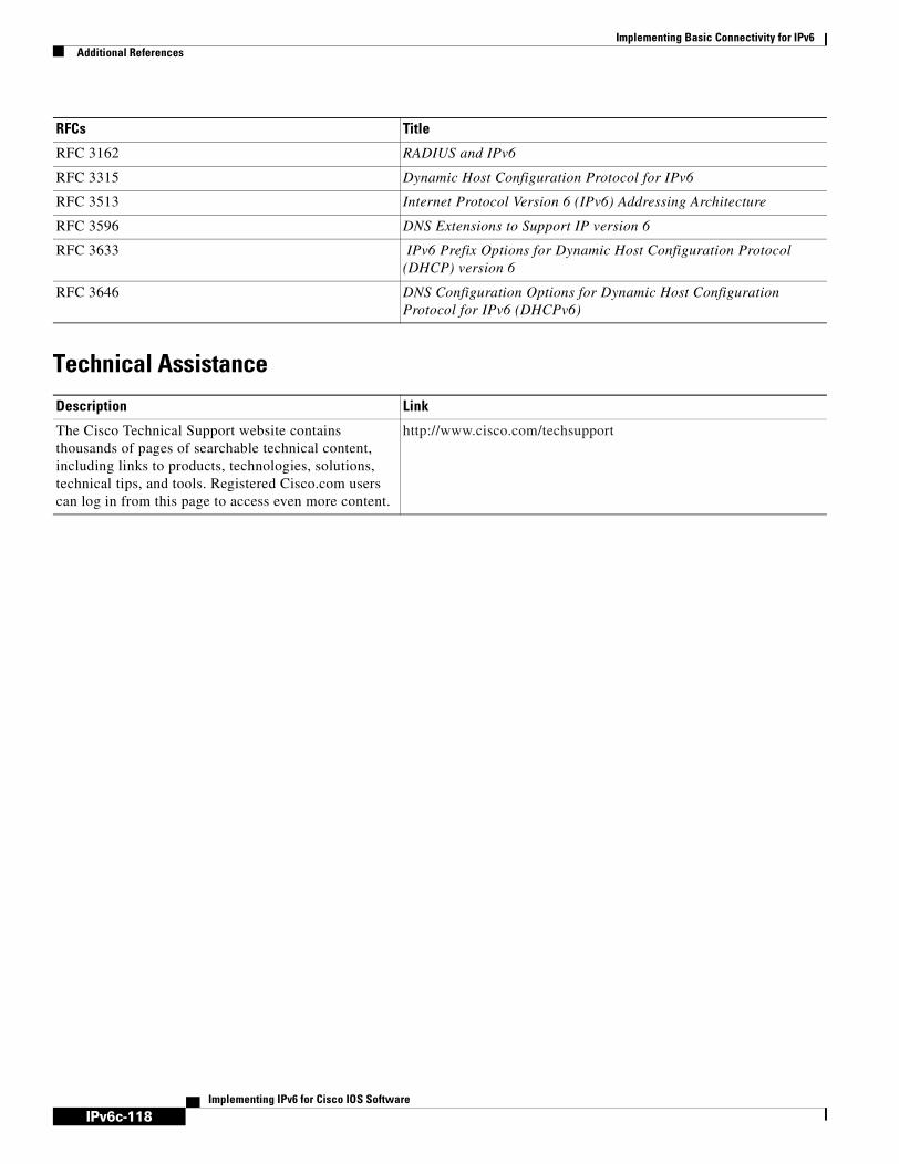
IPv6c-118
Implementing Basic Connectivity for IPv6Additional References
Implementing IPv6 for Cisco IOS Software
Technical Assistance
RFC 3162 RADIUS and IPv6
RFC 3315 Dynamic Host Configuration Protocol for IPv6
RFC 3513 Internet Protocol Version 6 (IPv6) Addressing Architecture
RFC 3596 DNS Extensions to Support IP version 6
RFC 3633 IPv6 Prefix Options for Dynamic Host Configuration Protocol (DHCP) version 6
RFC 3646 DNS Configuration Options for Dynamic Host Configuration Protocol for IPv6 (DHCPv6)
Description Link
The Cisco Technical Support website contains thousands of pages of searchable technical content, including links to products, technologies, solutions, technical tips, and tools. Registered Cisco.com users can log in from this page to access even more content.
http://www.cisco.com/techsupport
RFCs Title

IPv6c-119Implementing IPv6 for Cisco IOS Software
Implementing Multiprotocol BGP for IPv6
This module describes how to configure multiprotocol Border Gateway Protocol (BGP) for IPv6. BGP is an Exterior Gateway Protocol (EGP) used mainly to connect separate routing domains that contain independent routing policies (autonomous systems). Connecting to a service provider for access to the Internet is a common use for BGP. BGP can also be used within an autonomous system and this variation is referred to as internal BGP (iBGP). Multiprotocol BGP is an enhanced BGP that carries routing information for multiple network layer protocol address families, for example, IPv6 address family and for IP multicast routes. All BGP commands and routing policy capabilities can be used with multiprotocol BGP.
Finding Support Information for Platforms and Cisco IOS Software Images
Use Cisco Feature Navigator to find information about platform support and Cisco IOS software image support. Access Cisco Feature Navigator at http://www.cisco.com/go/fn. You must have an account on Cisco.com. If you do not have an account or have forgotten your username or password, click Cancel at the login dialog box and follow the instructions that appear.
Contents• Prerequisites for Implementing Multiprotocol BGP for IPv6, page 119
• Information About Implementing Multiprotocol BGP for IPv6, page 120
• How to Implement Multiprotocol BGP for IPv6, page 121
• Configuration Examples for Multiprotocol BGP for IPv6, page 147
• Where to Go Next, page 149
• Additional References, page 149
Prerequisites for Implementing Multiprotocol BGP for IPv6• This module assumes that you are familiar with IPv6 addressing and basic configuration. Refer to
the Implementing Basic Connectivity for IPv6 module for more information.
• This module assumes that you are familiar with IPv4. Refer to the publications referenced in the “Related Documents” section for IPv4 configuration and command reference information, as needed.
Table 6 identifies the earliest release for each early-deployment train in which each feature became available.

IPv6c-120
Implementing Multiprotocol BGP for IPv6Information About Implementing Multiprotocol BGP for IPv6
Implementing IPv6 for Cisco IOS Software
Information About Implementing Multiprotocol BGP for IPv6To configure multiprotocol BGP extensions for IPv6, you need to understand the following concept:
• Multiprotocol BGP Extensions for IPv6, page 120
• Multiprotocol BGP for the IPv6 Multicast Address Family, page 120
Multiprotocol BGP Extensions for IPv6Multiprotocol BGP is the supported EGP for IPv6. Multiprotocol BGP extensions for IPv6 supports the same features and functionality as IPv4 BGP. IPv6 enhancements to multiprotocol BGP include support for an IPv6 address family and network layer reachability information (NLRI) and next hop (the next router in the path to the destination) attributes that use IPv6 addresses.
Multiprotocol BGP for the IPv6 Multicast Address FamilyThe multiprotocol BGP for the IPv6 multicast address family feature provides multicast BGP extensions for IPv6 and supports the same features and functionality as IPv4 BGP. IPv6 enhancements to multicast BGP include support for an IPv6 multicast address family and network layer reachability information (NLRI) and next hop (the next router in the path to the destination) attributes that use IPv6 addresses.
Table 6 Minimum Required Cisco IOS Release
FeatureMinimum Required Cisco IOS Release by Release Train
Multiprotocol BGP extensions for IPv6 12.2(2)T, 12.0(21)ST, 12.0(22)S, 12.2(14)S, 12.3, 12.3(2)T, 12.4, 12.4(2)T, 12.2(28)SB
Configuring an IPv6 BGP routing process and BGP router ID
12.2(2)T, 12.0(21)ST, 12.0(22)S, 12.2(14)S, 12.3, 12.3(2)T, 12.4, 12.4(2)T, 12.2(28)SB
Configuring an IPv6 multiprotocol BGP Peer 12.2(2)T, 12.0(21)ST, 12.0(22)S, 12.2(14)S, 12.3, 12.3(2)T, 12.4, 12.4(2)T, 12.2(28)SB
Multiprotocol BGP link-local address peering 12.2(4)T, 12.0(21)ST, 12.0(22)S, 12.2(14)S, 12.3, 12.3(2)T, 12.4, 12.4(2)T, 12.2(28)SB
Configuring an IPv6 multiprotocol BGP peer group
12.2(2)T, 12.0(21)ST, 12.0(22)S, 12.2(14)S, 12.3, 12.3(2)T, 12.4, 12.4(2)T, 12.2(28)SB
Advertising routes into IPv6 multiprotocol BGP 12.2(2)T, 12.0(21)ST, 12.0(22)S, 12.2(14)S, 12.3, 12.3(2)T, 12.4, 12.4(2)T, 12.2(28)SB
Configuring route maps for IPv6 multiprotocol BGP prefixes
12.2(2)T, 12.0(21)ST, 12.0(22)S, 12.2(14)S, 12.3, 12.3(2)T, 12.4, 12.4(2)T, 12.2(28)SB
Redistributing prefixes into IPv6 multiprotocol BGP
12.2(2)T, 12.0(21)ST, 12.0(22)S, 12.2(14)S, 12.3, 12.3(2)T, 12.4, 12.4(2)T, 12.2(28)SB
IPv6 multicast address family support for multiprotocol BGP
12.0(26)S, 12.2(25)S, 12.2(28)SB
6PE multipath 12.2(25)S, 12.2(28)SB

IPv6c-121
Implementing Multiprotocol BGP for IPv6How to Implement Multiprotocol BGP for IPv6
Implementing IPv6 for Cisco IOS Software
Multicast BGP is an enhanced BGP that allows the deployment of interdomain IPv6 multicast. Multiprotocol BGP carries routing information for multiple network layer protocol address families; for example, IPv6 address family and for IPv6 multicast routes. The IPv6 multicast address family contains routes used for RPF lookup by the IPv6 PIM protocol, and multicast BGP IPV6 provides for inter- domain transport of the same. Users must use multiprotocol BGP for IPv6 multicast when using IPv6 multicast with BGP because the unicast BGP learned routes will not be used for IPv6 multicast.
Multicast BGP functionality is provided through a separate address family context. A subsequent address family identifier (SAFI) provides information about the type of the network layer reachability information that is carried in the attribute. Multiprotocol BGP unicast uses SAFI 1 messages, and multiprotocol BGP multicast uses SAFI 2 messages. SAFI 1 messages indicate that the routes are only usable for IP unicast, but not IP multicast. Because of this functionality, BGP routes in the IPv6 unicast RIB must be ignored in the IPv6 multicast RPF lookup.
A separate BGP routing table is maintained to configure incongruent policies and topologies (for example, IPv6 unicast and multicast) by using IPv6 multicast RPF lookup. Multicast RPF lookup is very similar to the IP unicast route lookup.
No MRIB is associated with the IPv6 multicast BGP table. However, IPv6 multicast BGP operates on the unicast IPv6 RIB when needed. Multicast BGP does not insert or update routes into the IPv6 unicast RIB.
6PE Multipath
Internal and external BGP multipath for IPv6 allows the IPv6 router to load balance between several paths (for example, same neighboring autonomous system [AS] or sub-AS, or the same metric) to reach its destination. The 6PE multipath feature uses multiprotocol internal BGP (MP-iBGP) to distribute IPv6 routes over the MPLS IPv4 core network and to attach an MPLS label to each route.
When MP-iBGP multipath is enabled on the 6PE router, all labeled paths are installed in the forwarding table with MPLS information (label stack) when MPLS information is available. This functionality enables 6PE to perform load balancing.
How to Implement Multiprotocol BGP for IPv6When configuring multiprotocol BGP extensions for IPv6, you must create the BGP routing process, configure peering relationships, and customize BGP for your particular network.
Note The following sections describe the configuration tasks for creating an IPv6 multiprotocol BGP routing process and associating peers, peer groups, and networks to the routing process. The following sections do not provide in-depth information on customizing multiprotocol BGP because the protocol functions the same in IPv6 as it does in IPv4. See the “Related Documents” section for further information on BGP and multiprotocol BGP configuration and command reference information.
The tasks in the following sections explain how to configure multiprotocol BGP extensions for IPv6. Each task in the list is identified as either required or optional:
• Configuring an IPv6 BGP Routing Process and BGP Router ID, page 122 (required)
• Configuring an IPv6 Multiprotocol BGP Peer, page 123 (required)
• Configuring an IPv6 Multiprotocol BGP Peer Using a Link-Local Address, page 124 (optional)
• Configuring an IPv6 Multiprotocol BGP Peer Group, page 128 (optional)

IPv6c-122
Implementing Multiprotocol BGP for IPv6How to Implement Multiprotocol BGP for IPv6
Implementing IPv6 for Cisco IOS Software
• Advertising Routes into IPv6 Multiprotocol BGP, page 131 (required)
• Configuring a Route Map for IPv6 Multiprotocol BGP Prefixes, page 132 (optional)
• Redistributing Prefixes into IPv6 Multiprotocol BGP, page 134 (optional)
• Advertising IPv4 Routes Between IPv6 BGP Peers, page 136 (optional)
• Assigning a BGP Administrative Distance, page 138 (optional)
• Generating Translate Updates for IPv6 Multicast BGP, page 139 (optional)
• Resetting BGP Sessions, page 141 (optional)
• Clearing External BGP Peers, page 141 (optional)
• Clearing IPv6 BGP Route Dampening Information, page 142 (optional)
• Clearing IPv6 BGP Flap Statistics, page 143 (optional)
• Verifying IPv6 Multiprotocol BGP Configuration and Operation, page 143 (optional)
Configuring an IPv6 BGP Routing Process and BGP Router IDThis task explains how to configure an IPv6 BGP routing process and an optional BGP router ID for a BGP-speaking router.
Prerequisites
Before configuring the router to run BGP for IPv6, you must globally enable IPv6 routing using the ipv6 unicast-routing global configuration command. For details on basic IPv6 connectivity tasks, refer to the Implementing Basic Connectivity for IPv6 module.
BGP Router ID for IPv6
BGP uses a router ID to identify BGP-speaking peers. The BGP router ID is 32-bit value that is often represented by an IPv4 address. By default, the Cisco IOS software sets the router ID to the IPv4 address of a loopback interface on the router. If no loopback interface is configured on the router, then the software chooses the highest IPv4 address configured to a physical interface on the router to represent the BGP router ID. When configuring BGP on a router that is enabled only for IPv6 (the router does not have an IPv4 address), you must manually configure the BGP router ID for the router. The BGP router ID, which is represented as a 32-bit value using an IPv4 address syntax, must be unique to the BGP peers of the router.
SUMMARY STEPS
1. enable
2. configure terminal
3. router bgp autonomous-system-number
4. no bgp default ipv4-unicast
5. bgp router-id ip-address

IPv6c-123
Implementing Multiprotocol BGP for IPv6How to Implement Multiprotocol BGP for IPv6
Implementing IPv6 for Cisco IOS Software
DETAILED STEPS
Configuring an IPv6 Multiprotocol BGP PeerThis task explains how to configure IPv6 multiprotocol BGP between two IPv6 routers (peers).
Restrictions
By default, neighbors that are defined using the neighbor remote-as command in router configuration mode exchange only IPv4 unicast address prefixes. To exchange other address prefix types, such as IPv6 prefixes, neighbors must also be activated using the neighbor activate command in address family configuration mode for the other prefix types, as shown for IPv6 prefixes.
SUMMARY STEPS
1. enable
2. configure terminal
3. router bgp autonomous-system-number
Command or Action Purpose
Step 1 enable
Example:Router> enable
Enables privileged EXEC mode.
• Enter your password if prompted.
Step 2 configure terminal
Example:Router# configure terminal
Enters global configuration mode.
Step 3 router bgp autonomous-system-number
Example:Router(config)# router bgp 65000
Configures a BGP routing process, and enters router configuration mode for the specified routing process.
Step 4 no bgp default ipv4-unicast
Example:Router(config-router)# no bgp default ipv4-unicast
Disables the IPv4 unicast address family for the BGP routing process specified in the previous step.
Note Routing information for the IPv4 unicast address family is advertised by default for each BGP routing session configured with the neighbor remote-as router configuration command unless you configure the no bgp default ipv4-unicast router configuration command before configuring the neighbor remote-as command.
Step 5 bgp router-id ip-address
Example:Router(config-router)# bgp router-id 192.168.99.70
(Optional) Configures a fixed 32-bit router ID as the identifier of the local router running BGP.
Note Configuring a router ID using the bgp router-id command resets all active BGP peering sessions.

IPv6c-124
Implementing Multiprotocol BGP for IPv6How to Implement Multiprotocol BGP for IPv6
Implementing IPv6 for Cisco IOS Software
4. neighbor ipv6-address remote-as autonomous-system-number
5. address-family ipv6 [unicast | multicast]
6. neighbor ipv6-address activate
DETAILED STEPS
Configuring an IPv6 Multiprotocol BGP Peer Using a Link-Local AddressThis task explains how to configure IPv6 multiprotocol BGP between two peers using link-local addresses.
Command or Action Purpose
Step 1 enable
Example:Router> enable
Enables privileged EXEC mode.
• Enter your password if prompted.
Step 2 configure terminal
Example:Router# configure terminal
Enters global configuration mode.
Step 3 router bgp autonomous-system-number
Example:Router(config)# router bgp 65000
Enters router configuration mode for the specified routing process.
Step 4 neighbor ipv6-address remote-as autonomous-system-number
Example:Router(config-router)# neighbor 2001:0DB8:0:CC00::1 remote-as 64600
Adds the IPv6 address of the neighbor in the specified autonomous system to the IPv6 multiprotocol BGP neighbor table of the local router.
• The ipv6-address argument in the neighbor remote-as command must be in the form documented in RFC 2373 where the address is specified in hexadecimal using 16-bit values between colons.
Step 5 address-family ipv6 [unicast | multicast]
Example:Router(config-router)# address-family ipv6
Specifies the IPv6 address family and enters address family configuration mode.
• The unicast keyword specifies the IPv6 unicast address family. By default, the router is placed in configuration mode for the IPv6 unicast address family if the unicast keyword is not specified with the address-family ipv6 command.
• The multicast keyword specifies IPv6 multicast address prefixes.
Step 6 neighbor ipv6-address activate
Example:Router(config-router-af)# neighbor 2001:0DB8:0:CC00::1 activate
Enables the neighbor to exchange prefixes for the IPv6 address family with the local router.

IPv6c-125
Implementing Multiprotocol BGP for IPv6How to Implement Multiprotocol BGP for IPv6
Implementing IPv6 for Cisco IOS Software
Multiprotocol BGP Peering Using Link-Local Addresses
Configuring IPv6 multiprotocol BGP between two IPv6 routers (peers) using link-local addresses requires that the interface for the neighbor be identified by using the update-source router configuration command and that a route map be configured to set an IPv6 global next hop.
Restrictions
• By default, neighbors that are defined using the neighbor remote-as command in router configuration mode exchange only IPv4 unicast address prefixes. To exchange other address prefix types, such as IPv6 prefixes, neighbors must also be activated using the neighbor activate command in address family configuration mode for the other prefix types, as shown for IPv6 prefixes.
• By default, route maps that are applied in router configuration mode using the neighbor route-map command are applied to only IPv4 unicast address prefixes. Route maps for other address families must be applied in address family configuration mode using the neighbor route-map command, as shown for the IPv6 address family. The route maps are applied either as the inbound or outbound routing policy for neighbors under the specified address family. Configuring separate route maps under each address family type simplifies managing complicated or different policies for each address family.
SUMMARY STEPS
1. enable
2. configure terminal
3. router bgp autonomous-system-number
4. neighbor ipv6-address remote-as autonomous-system-number
5. neighbor ipv6-address update-source interface-type
6. address-family ipv6 [unicast | multicast]
7. neighbor ipv6-address activate
8. neighbor ipv6-address route-map map-name {in | out}
9. exit
10. Repeat Step 9.
11. route-map map-name [permit | deny] [sequence-number]
12. match ipv6 address prefix-list prefix-list-name
13. set ipv6 next-hop ipv6-address [link-local-address]

IPv6c-126
Implementing Multiprotocol BGP for IPv6How to Implement Multiprotocol BGP for IPv6
Implementing IPv6 for Cisco IOS Software
DETAILED STEPS
Command or Action Purpose
Step 1 enable
Example:Router> enable
Enables privileged EXEC mode.
• Enter your password if prompted.
Step 2 configure terminal
Example:Router# configure terminal
Enters global configuration mode.
Step 3 router bgp autonomous-system-number
Example:Router(config)# router bgp 65000
Enters router configuration mode for the specified routing process.
Step 4 neighbor ipv6-address remote-as autonomous-system-number
Example:Router(config-router)# neighbor FE80::XXXX:BFF:FE0E:A471 remote-as 64600
Adds the link-local IPv6 address of the neighbor in the specified remote autonomous system to the IPv6 multiprotocol BGP neighbor table of the local router.
• The ipv6-address argument in the neighbor remote-as command must be a link-local IPv6 address in the form documented in RFC 2373 where the address is specified in hexadecimal using 16-bit values between colons.
Step 5 neighbor ipv6-address update-source interface-type interface-number
Example:Router(config-router)# neighbor FE80::XXXX:BFF:FE0E:A471 update-source fastethernet0
Specifies the link-local address over which the peering is to occur.
• If there are multiple connections to the neighbor and you do not specify the neighbor interface by using the interface-type and interface-number arguments in the neighbor update-source command, a TCP connection cannot be established with the neighbor using link-local addresses.
Step 6 address-family ipv6 [unicast | multicast]
Example:Router(config-router)# address-family ipv6
Specifies the IPv6 address family, and enters address family configuration mode.
• The unicast keyword specifies the IPv6 unicast address family. By default, the router is placed in configuration mode for the IPv6 unicast address family if the unicast keyword is not specified with the address-family ipv6 command.
• The multicast keyword specifies IPv6 multicast address prefixes.
Step 7 neighbor ipv6-address activate
Example:Router(config-router-af)# neighbor FE80::XXXX:BFF:FE0E:A471 activate
Enables the neighbor to exchange prefixes for the IPv6 address family with the local router using the specified link-local addresses.
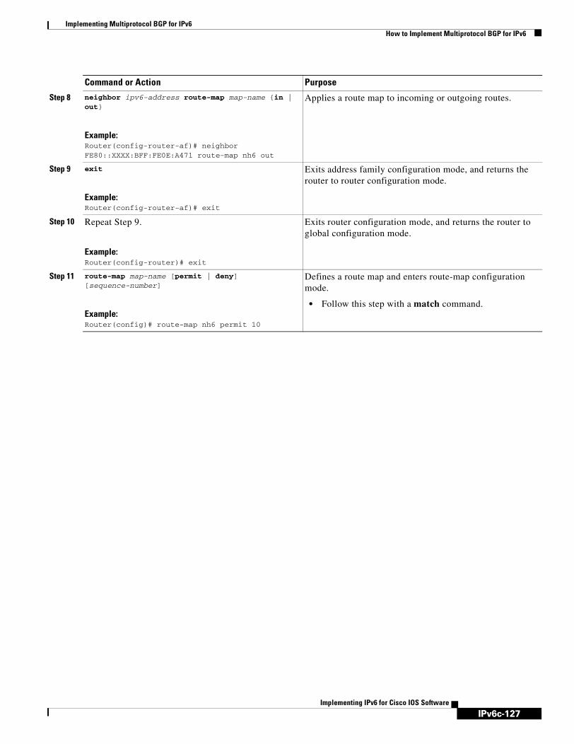
IPv6c-127
Implementing Multiprotocol BGP for IPv6How to Implement Multiprotocol BGP for IPv6
Implementing IPv6 for Cisco IOS Software
Step 8 neighbor ipv6-address route-map map-name {in | out}
Example:Router(config-router-af)# neighbor FE80::XXXX:BFF:FE0E:A471 route-map nh6 out
Applies a route map to incoming or outgoing routes.
Step 9 exit
Example:Router(config-router-af)# exit
Exits address family configuration mode, and returns the router to router configuration mode.
Step 10 Repeat Step 9.
Example:Router(config-router)# exit
Exits router configuration mode, and returns the router to global configuration mode.
Step 11 route-map map-name [permit | deny] [sequence-number]
Example:Router(config)# route-map nh6 permit 10
Defines a route map and enters route-map configuration mode.
• Follow this step with a match command.
Command or Action Purpose

IPv6c-128
Implementing Multiprotocol BGP for IPv6How to Implement Multiprotocol BGP for IPv6
Implementing IPv6 for Cisco IOS Software
Troubleshooting Tips
Peering not established by this task may be due to a missing route map set ipv6 next-hop command. Use the debug bgp ipv6 update command to display debugging information on the updates to help determine the state of the peering.
Configuring an IPv6 Multiprotocol BGP Peer GroupThis task explains how to configure an IPv6 peer group to perform multiprotocol BGP routing.
Step 12 match ipv6 address prefix-list prefix-list-name
Example:Router(config-route-map)# match ipv6 address prefix-list cisco
Distributes any routes that have a destination IPv6 network number address permitted by a prefix list, or performs policy routing on packets.
• Follow this step with a set command.
Step 13 set ipv6 next-hop ipv6-address [link-local-address]
Example:Router(config-route-map)# set ipv6 next-hop 2001:0DB8::1
Overrides the next hop advertised to the peer for IPv6 packets that pass a match clause of a route map for policy routing.
• The ipv6-address argument specifies the IPv6 global address of the next hop. It need not be an adjacent router.
• The link-local-address argument specifies the IPv6 link-local address of the next hop. It must be an adjacent router.
Note The route map sets the IPv6 next-hop addresses (global and link-local) in BGP updates. If the route map is not configured, the next-hop address in the BGP updates defaults to the unspecified IPv6 address (::), which is rejected by the peer.
If you specify only the global IPv6 next-hop address (the ipv6-address argument) with the set ipv6 next-hop command after specifying the neighbor interface (the interface-type argument) with the neighbor update-source command in Step 5, the link-local address of the interface specified with the interface-type argument is included as the next-hop in the BGP updates. Therefore, only one route map that sets the global IPv6 next-hop address in BGP updates is required for multiple BGP peers that use link-local addresses.
Command or Action Purpose
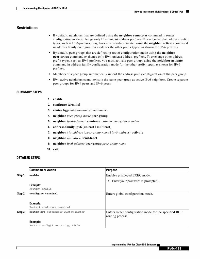
IPv6c-129
Implementing Multiprotocol BGP for IPv6How to Implement Multiprotocol BGP for IPv6
Implementing IPv6 for Cisco IOS Software
Restrictions
• By default, neighbors that are defined using the neighbor remote-as command in router configuration mode exchange only IPv4 unicast address prefixes. To exchange other address prefix types, such as IPv6 prefixes, neighbors must also be activated using the neighbor activate command in address family configuration mode for the other prefix types, as shown for IPv6 prefixes.
• By default, peer groups that are defined in router configuration mode using the neighbor peer-group command exchange only IPv4 unicast address prefixes. To exchange other address prefix types, such as IPv6 prefixes, you must activate peer groups using the neighbor activate command in address family configuration mode for the other prefix types, as shown for IPv6 prefixes.
• Members of a peer group automatically inherit the address prefix configuration of the peer group.
• IPv4 active neighbors cannot exist in the same peer group as active IPv6 neighbors. Create separate peer groups for IPv4 peers and IPv6 peers.
SUMMARY STEPS
1. enable
2. configure terminal
3. router bgp autonomous-system-number
4. neighbor peer-group-name peer-group
5. neighbor ipv6-address remote-as autonomous-system-number
6. address-family ipv6 [unicast | multicast]
7. neighbor {ip-address | peer-group-name | ipv6-address} activate
8. neighbor ip-address send-label
9. neighbor ipv6-address peer-group peer-group-name
10. exit
DETAILED STEPS
Command or Action Purpose
Step 1 enable
Example:Router> enable
Enables privileged EXEC mode.
• Enter your password if prompted.
Step 2 configure terminal
Example:Router# configure terminal
Enters global configuration mode.
Step 3 router bgp autonomous-system-number
Example:Router(config)# router bgp 65000
Enters router configuration mode for the specified BGP routing process.

IPv6c-130
Implementing Multiprotocol BGP for IPv6How to Implement Multiprotocol BGP for IPv6
Implementing IPv6 for Cisco IOS Software
Step 4 neighbor peer-group-name peer-group
Example:Router(config-router)# neighbor group1 peer-group
Creates a multiprotocol BGP peer group.
Step 5 neighbor ipv6-address remote-as autonomous-system-number
Example:Router(config-router)# neighbor 2001:0DB8:0:CC00::1 remote-as 64600
Adds the IPv6 address of the neighbor in the specified autonomous system to the IPv6 multiprotocol BGP neighbor table of the local router.
• The ipv6-address argument in the neighbor remote-as command must be in the form documented in RFC 2373 where the address is specified in hexadecimal using 16-bit values between colons.
Step 6 address-family ipv6 [unicast | multicast]
Example:Router(config-router)# address-family ipv6 unicast
Specifies the IPv6 address family, and enters address family configuration mode.
• The unicast keyword specifies the IPv6 unicast address family. By default, the router is placed in configuration mode for the IPv6 unicast address family if the unicast keyword is not specified with the address-family ipv6 command.
• The multicast keyword specifies IPv6 multicast address prefixes.
Step 7 neighbor {ip-address | peer-group-name | ipv6-address} activate
Example:Router(config-router-af)# neighbor 2001:0DB8:0:CC00::1 activate
Enables the neighbor to exchange prefixes for the specified family type with the neighbor and the local router.
• To avoid extra configuration steps for each neighbor, use the neighbor activate command with the peer-group-name argument as an alternative in this step.
Step 8 neighbor ip-address send-label
Example:Router(config-router-af)# neighbor 192.168.99.70 send-label
Advertises the capability of the router to send MPLS labels with BGP routes.
• In IPv6 address family configuration mode, this command enables binding and advertisement of aggregate labels when advertising IPv6 prefixes in BGP.
Step 9 neighbor ipv6-address peer-group peer-group-name
Example:Router(config-router-af)# neighbor 2001:0DB8:0:CC00::1 peer-group group1
Assigns the IPv6 address of a BGP neighbor to a peer group.
Step 10 exit
Example:Router(config-router-af)# exit
Exits address family configuration mode, and returns the router to router configuration mode.
• Repeat this step to exit router configuration mode and return the router to global configuration mode.
Command or Action Purpose

IPv6c-131
Implementing Multiprotocol BGP for IPv6How to Implement Multiprotocol BGP for IPv6
Implementing IPv6 for Cisco IOS Software
What to Do Next
Refer to the section “Configure BGP Peer Groups” of the “Configuring BGP” chapter in Cisco IOS IP Configuration Guide, Release 12.4, for more information on assigning options to peer groups and making a BGP or multiprotocol BGP neighbor a member of a peer group.
Advertising Routes into IPv6 Multiprotocol BGPThis task explains how to advertise (inject) a prefix into IPv6 multiprotocol BGP.
Restrictions
By default, networks that are defined in router configuration mode using the network command are injected into the IPv4 unicast database. To inject a network into another database, such as the IPv6 BGP database, you must define the network using the network command in address family configuration mode for the other database, as shown for the IPv6 BGP database.
SUMMARY STEPS
1. enable
2. configure terminal
3. router bgp autonomous-system-number
4. address-family ipv6 [unicast | multicast]
5. network ipv6-address/prefix-length
6. exit
DETAILED STEPS
Command or Action Purpose
Step 1 enable
Example:Router> enable
Enables privileged EXEC mode.
• Enter your password if prompted.
Step 2 configure terminal
Example:Router# configure terminal
Enters global configuration mode.
Step 3 router bgp autonomous-system-number
Example:Router(config)# router bgp 65000
Enters router configuration mode for the specified BGP routing process.

IPv6c-132
Implementing Multiprotocol BGP for IPv6How to Implement Multiprotocol BGP for IPv6
Implementing IPv6 for Cisco IOS Software
Configuring a Route Map for IPv6 Multiprotocol BGP PrefixesThis task explains how to configure a route map for IPv6 multiprotocol BGP prefixes.
Restrictions
• By default, neighbors that are defined using the neighbor remote-as command in router configuration mode exchange only IPv4 unicast address prefixes. To exchange other address prefix types, such as IPv6 prefixes, neighbors must also be activated using the neighbor activate command in address family configuration mode for the other prefix types, as shown for IPv6 prefixes.
• By default, route maps that are applied in router configuration mode using the neighbor route-map command are applied to only IPv4 unicast address prefixes. Route maps for other address families must be applied in address family configuration mode using the neighbor route-map command, as shown for the IPv6 address family. The route maps are applied either as the inbound or outbound
Step 4 address-family ipv6 [unicast | multicast]
Example:Router(config-router)# address-family ipv6 unicast
Specifies the IPv6 address family, and enters address family configuration mode.
• The unicast keyword specifies the IPv6 unicast address family. By default, the router is placed in configuration mode for the IPv6 unicast address family if the unicast keyword is not specified with the address-family ipv6 command.
• The multicast keyword specifies IPv6 multicast address prefixes.
Step 5 network ipv6-address/prefix-length
Example:Router(config-router-af)# network 2001:0DB8::/24
Advertises (injects) the specified prefix into the IPv6 BGP database. (The routes must first be found in the IPv6 unicast routing table.)
• Specifically, the prefix is injected into the database for the address family specified in the previous step.
• Routes are tagged from the specified prefix as “local origin.”
• The ipv6-prefix argument in the network command must be in the form documented in RFC 2373 where the address is specified in hexadecimal using 16-bit values between colons.
• The prefix-length argument is a decimal value that indicates how many of the high-order contiguous bits of the address comprise the prefix (the network portion of the address). A slash mark must precede the decimal value.
Step 6 exit
Example:Router(config-router-af)# exit
Exits address family configuration mode, and returns the router to router configuration mode.
• Repeat this step to exit router configuration mode and return the router to global configuration mode.
Command or Action Purpose
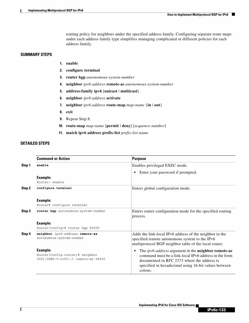
IPv6c-133
Implementing Multiprotocol BGP for IPv6How to Implement Multiprotocol BGP for IPv6
Implementing IPv6 for Cisco IOS Software
routing policy for neighbors under the specified address family. Configuring separate route maps under each address family type simplifies managing complicated or different policies for each address family.
SUMMARY STEPS
1. enable
2. configure terminal
3. router bgp autonomous-system-number
4. neighbor ipv6-address remote-as autonomous-system-number
5. address-family ipv6 [unicast | multicast]
6. neighbor ipv6-address activate
7. neighbor ipv6-address route-map map-name {in | out}
8. exit
9. Repeat Step 8.
10. route-map map-name [permit | deny] [sequence-number]
11. match ipv6 address prefix-list prefix-list-name
DETAILED STEPS
Command or Action Purpose
Step 1 enable
Example:Router> enable
Enables privileged EXEC mode.
• Enter your password if prompted.
Step 2 configure terminal
Example:Router# configure terminal
Enters global configuration mode.
Step 3 router bgp autonomous-system-number
Example:Router(config)# router bgp 65000
Enters router configuration mode for the specified routing process.
Step 4 neighbor ipv6-address remote-as autonomous-system-number
Example:Router(config-router)# neighbor 2001:0DB8:0:cc00::1 remote-as 64600
Adds the link-local IPv6 address of the neighbor in the specified remote autonomous system to the IPv6 multiprotocol BGP neighbor table of the local router.
• The ipv6-address argument in the neighbor remote-as command must be a link-local IPv6 address in the form documented in RFC 2373 where the address is specified in hexadecimal using 16-bit values between colons.

IPv6c-134
Implementing Multiprotocol BGP for IPv6How to Implement Multiprotocol BGP for IPv6
Implementing IPv6 for Cisco IOS Software
Redistributing Prefixes into IPv6 Multiprotocol BGPThis task explains how to redistribute (inject) prefixes from another routing protocol into IPv6 multiprotocol BGP.
Step 5 address-family ipv6 [unicast | multicast]
Example:Router(config-router)# address-family ipv6
Specifies the IPv6 address family, and enters address family configuration mode.
• The unicast keyword specifies the IPv6 unicast address family. By default, the router is placed in configuration mode for the IPv6 unicast address family if the unicast keyword is not specified with the address-family ipv6 command.
• The multicast keyword specifies IPv6 multicast address prefixes.
Step 6 neighbor ipv6-address activate
Example:Router(config-router-af)# neighbor 2001:0DB8:0:cc00::1 activate
Enables the neighbor to exchange prefixes for the IPv6 address family with the local router using the specified link-local addresses.
Step 7 neighbor ipv6-address route-map map-name {in | out}
Example:Router(config-router-af)# neighbor 2001:0DB8:0:cc00::1 route-map rtp in
Applies a route map to incoming or outgoing routes.
• Changes to the route map will not take effect for existing peers until the peering is reset or a soft reset is performed. Using the clear bgp ipv6 command with the soft and in keywords will perform a soft reset.
Step 8 exit
Example:Router(config-router-af)# exit
Exits address family configuration mode, and returns the router to router configuration mode.
Step 9 Repeat Step 8.
Example:Router(config-router)# exit
Exits router configuration mode, and returns the router to global configuration mode.
Step 10 route-map map-name [permit | deny] [sequence-number]
Example:Router(config)# route-map rtp permit 10
Defines a route map and enters route-map configuration mode.
• Follow this step with a match command.
Step 11 match ipv6 address prefix-list prefix-list-name
Example:Router(config-route-map)# match ipv6 address prefix-list cisco
Distributes any routes that have a destination IPv6 network number address permitted by a prefix list, or performs policy routing on packets.
Command or Action Purpose

IPv6c-135
Implementing Multiprotocol BGP for IPv6How to Implement Multiprotocol BGP for IPv6
Implementing IPv6 for Cisco IOS Software
Redistribution for IPv6
Redistribution is the process of injecting prefixes from one routing protocol into another routing protocol. This task explains how to inject prefixes from a routing protocol into IPv6 multiprotocol BGP. Specifically, prefixes that are redistributed into IPv6 multiprotocol BGP using the redistribute router configuration command are injected into the IPv6 unicast database.
SUMMARY STEPS
1. enable
2. configure terminal
3. router bgp autonomous-system-number
4. address-family ipv6 [unicast | multicast]
5. redistribute protocol [process-id] [level-1 | level-1-2 | level-2] [metric metric-value] [metric-type {internal | external}] [route-map map-name]
6. exit
DETAILED STEPS
Command or Action Purpose
Step 1 enable
Example:Router> enable
Enables privileged EXEC mode.
• Enter your password if prompted.
Step 2 configure terminal
Example:Router# configure terminal
Enters global configuration mode.
Step 3 router bgp autonomous-system-number
Example:Router(config)# router bgp 65000
Enters router configuration mode for the specified BGP routing process.
Step 4 address-family ipv6 [unicast | multicast]
Example:Router(config-router)# address-family ipv6
Specifies the IPv6 address family, and enters address family configuration mode.
• The unicast keyword specifies the IPv6 unicast address family. By default, the router is placed in configuration mode for the IPv6 unicast address family if the unicast keyword is not specified with the address-family ipv6 command.
• The multicast keyword specifies IPv6 multicast address prefixes.

IPv6c-136
Implementing Multiprotocol BGP for IPv6How to Implement Multiprotocol BGP for IPv6
Implementing IPv6 for Cisco IOS Software
Advertising IPv4 Routes Between IPv6 BGP PeersThis task explains how to advertise IPv4 routes between IPv6 peers. If an IPv6 network is connecting two separate IPv4 networks, it is possible to use IPv6 to advertise the IPv4 routes. Configure the peering using the IPv6 addresses within the IPv4 address family. Set the next hop with a static route or with an inbound route map because the advertised next hop will usually be unreachable. Advertising IPv6 routes between two IPv4 peers is also possible using the same model.
SUMMARY STEPS
1. enable
2. configure terminal
3. router bgp autonomous-system-number
4. neighbor peer-group-name peer-group
5. neighbor peer-group-name remote-as autonomous-system-number
6. address-family ipv4
7. neighbor ipv6-address peer-group peer-group-name
8. neighbor peer-group-name route-map map-name {in | out}
9. exit
10. Repeat Step 11.
11. route-map map-name [permit | deny] [sequence-number]
12. set ip next-hop ipv4-address [peer-address]
Step 5 redistribute protocol [process-id] [level-1 | level-1-2 | level-2] [metric metric-value] [metric-type {internal | external}] [route-map map-name]
Example:Router(config-router-af)# redistribute rip
Specifies the routing protocol from which prefixes should be redistributed into IPv6 multiprotocol BGP.
• The protocol argument can be one of the following keywords: bgp, connected, isis, rip, or static.
Note The connected keyword refers to routes that are established automatically by IPv6 having been enabled on an interface.
Step 6 exit
Example:Router(config-router-af)# exit
Exits address family configuration mode, and returns the router to router configuration mode.
• Repeat this step to exit router configuration mode and return the router to global configuration mode.
Command or Action Purpose

IPv6c-137
Implementing Multiprotocol BGP for IPv6How to Implement Multiprotocol BGP for IPv6
Implementing IPv6 for Cisco IOS Software
DETAILED STEPS
Command or Action Purpose
Step 1 enable
Example:Router> enable
Enables privileged EXEC mode.
• Enter your password if prompted.
Step 2 configure terminal
Example:Router# configure terminal
Enters global configuration mode.
Step 3 router bgp autonomous-system-number
Example:Router(config)# router bgp 65000
Enters router configuration mode for the specified routing process.
Step 4 neighbor peer-group-name peer-group
Example:Router(config-router)# neighbor 6peers peer-group
Creates a multiprotocol BGP peer group.
Step 5 neighbor peer-group-name remote-as autonomous-system-number
Example:Router(config-router)# neighbor 6peers remote-as 65002
Adds the IPv6 address of the neighbor in the specified autonomous system to the IPv6 multiprotocol BGP neighbor table of the local router.
• The ipv6-address argument in the neighbor remote-as command must be in the form documented in RFC 2373 where the address is specified in hexadecimal using 16-bit values between colons.
Step 6 address-family ipv4
Example:Router(config-router)# address-family ipv4
Specifies the IPv4 address family, and enters address family configuration mode.
Step 7 neighbor ipv6-address peer-group peer-group-name
Example:Router(config-router-af)# neighbor 2001:0DB8:yyyy::2 peer-group 6peers
Assigns the IPv6 address of a BGP neighbor to a peer group.
Step 8 neighbor peer-group-name route-map map-name {in | out}
Example:Router(config-router-af)# neighbor 6peers route-map rmap out
Applies a route map to incoming or outgoing routes.
• Changes to the route map will not take effect for existing peers until the peering is reset or a soft reset is performed. Using the clear bgp ipv6 command with the soft and in keywords will perform a soft reset.

IPv6c-138
Implementing Multiprotocol BGP for IPv6How to Implement Multiprotocol BGP for IPv6
Implementing IPv6 for Cisco IOS Software
Assigning a BGP Administrative DistanceThis task explains how to specify an administrative distance for multicast BGP routes to be used in RPF lookups for comparison with unicast routes.
Caution Changing the administrative distance of BGP internal routes is considered dangerous and is not recommended. One problem that can arise is the accumulation of routing table inconsistencies, which can break routing.
SUMMARY STEPS
1. enable
2. configure terminal
3. router bgp autonomous-system-number
4. address family ipv6 [unicast | multicast}
5. distance bgp external-distance internal-distance local-distance
Step 9 exit
Example:Router(config-router-af)# exit
Exits address family configuration mode, and returns the router to router configuration mode.
Step 10 Repeat Step 11.
Example:Router(config-router)# exit
Exits router configuration mode, and returns the router to global configuration mode.
Step 11 route-map map-name [permit | deny] [sequence-number]
Example:Router(config)# route-map rmap permit 10
Defines a route map and enters route-map configuration mode.
Step 12 set ip next-hop ipv4-address [peer-address]
Example:Router(config-route-map)# set ip next-hop 10.21.8.10
Overrides the next hop advertised to the peer for IPv4 packets.
Command or Action Purpose

IPv6c-139
Implementing Multiprotocol BGP for IPv6How to Implement Multiprotocol BGP for IPv6
Implementing IPv6 for Cisco IOS Software
DETAILED STEPS
Generating Translate Updates for IPv6 Multicast BGPThis task explains how to generate IPv6 multicast BGP updates that correspond to unicast IPv6 updates received from a peer.
The MBGP translate-update feature generally is used in an MBGP-capable router that peers with a customer site that has only a BGP-capable router; the customer site has not or cannot upgrade its router to an MBGP-capable image. Because the customer site cannot originate MBGP advertisements, the router with which it peers will translate the BGP prefixes into MBGP prefixes, which are used for multicast-source Reverse Path Forwarding (RPF) lookup.
SUMMARY STEPS
1. enable
2. configure terminal
3. router bgp autonomous-system-number
4. address-family ipv6 [unicast | multicast}
5. neighbor ipv6-address translate-update multicast
enable
Example:Router> enable
Enables privileged EXEC mode.
• Enter your password if prompted.
configure terminal
Example:Router# configure terminal
Enters global configuration mode.
router bgp autonomous-system-number
Example:Router(config)# router bgp 100
Enters router configuration mode for the specified routing process.
address family ipv6 [unicast | multicast}
Example:Router(config-router)# address-family ipv6 multicast
Enters address family configuration mode for configuring routing sessions such as BGP that use standard IPv6 address prefixes.
distance bgp external-distance internal-distance local-distance
Example:Router(config-router)# distance bgp 20 20 200
Assigns a BGP administrative distance.

IPv6c-140
Implementing Multiprotocol BGP for IPv6How to Implement Multiprotocol BGP for IPv6
Implementing IPv6 for Cisco IOS Software
DETAILED STEPS
enable
Example:Router> enable
Enables privileged EXEC mode.
• Enter your password if prompted.
configure terminal
Example:Router# configure terminal
Enters global configuration mode.
router bgp autonomous-system-number
Example:Router(config)# router bgp 100
Enters router configuration mode for the specified routing process.
address-family ipv6 [unicast | multicast}
Example:Router(config-router)# address-family ipv6 multicast
Enters address family configuration mode for configuring routing sessions such as BGP that use standard IPv6 address prefixes.
neighbor ipv6-address translate-update multicast
Example:Router(config-router)# neighbor 2001:0DB8::2 translate-update ipv6 multicast
Generates multiprotocol IPv6 BGP updates that correspond to unicast IPv6 updates received from a peer.

IPv6c-141
Implementing Multiprotocol BGP for IPv6How to Implement Multiprotocol BGP for IPv6
Implementing IPv6 for Cisco IOS Software
Resetting BGP SessionsThis task explains how to reset IPv6 BGP sessions.
SUMMARY STEPS
1. enable
2. clear bgp ipv6 {unicast | multicast} {* | autonomous-system-number | ip-address | ipv6-address | peer-group-name} [soft] [in | out]
DETAILED STEPS
Clearing External BGP PeersThis task explains how to clear external BGP peers and members of an IPv6 BGP peer group.
SUMMARY STEPS
1. enable
2. clear bgp ipv6 {unicast | multicast} external [soft] [in | out]
3. clear bgp ipv6 {unicast | multicast} peer-group [name]
Command or Action Purpose
Step 1 enable
Example:Router> enable
Enables privileged EXEC mode.
• Enter your password if prompted.
Step 2 clear bgp ipv6 {unicast | multicast} {* | autonomous-system-number | ip-address | ipv6-address | peer-group-name} [soft] [in | out]
Example:Router# clear bgp ipv6 unicast peer-group marketing soft out
Resets IPv6 BGP sessions.

IPv6c-142
Implementing Multiprotocol BGP for IPv6How to Implement Multiprotocol BGP for IPv6
Implementing IPv6 for Cisco IOS Software
DETAILED STEPS
Clearing IPv6 BGP Route Dampening InformationThis task explains how to clear IPv6 BGP route dampening information and how to unsuppress suppressed routes.
SUMMARY STEPS
1. enable
2. clear bgp ipv6 {unicast | multicast} dampening [ipv6-prefix/prefix-length]
DETAILED STEPS
Command or Action Purpose
Step 1 enable
Example:Router> enable
Enables privileged EXEC mode.
• Enter your password if prompted.
Step 2 clear bgp ipv6 {unicast | multicast} external [soft] [in | out]
Example:Router# clear bgp ipv6 unicast external soft in
Clears external IPv6 BGP peers.
Step 3 clear bgp ipv6 {unicast | multicast} peer-group [name]
Example:Router# clear bgp ipv6 unicast peer-group
Clears all members of an IPv6 BGP peer group.
Command or Action Purpose
Step 1 enable
Example:Router> enable
Enables privileged EXEC mode.
• Enter your password if prompted.
Step 2 clear bgp ipv6 {unicast | multicast} dampening [ipv6-prefix/prefix-length]
Example:Router# clear bgp ipv6 unicast dampening 2001:0DB8::/64
Clears IPv6 BGP route dampening information and unsuppress the suppressed routes.

IPv6c-143
Implementing Multiprotocol BGP for IPv6How to Implement Multiprotocol BGP for IPv6
Implementing IPv6 for Cisco IOS Software
Clearing IPv6 BGP Flap StatisticsThis task explains how to clear IPv6 BGP flap statistics.
SUMMARY STEPS
1. enable
2. clear bgp ipv6 {unicast | multicast} flap-statistics [ipv6-prefix/prefix-length | regexp regexp | filter-list list]
DETAILED STEPS
Verifying IPv6 Multiprotocol BGP Configuration and OperationThis task explains how to display information to verify the configuration and operation of IPv6 multiprotocol BGP.
SUMMARY STEPS
1. show bgp ipv6 {unicast | multicast} [ipv6-prefix/prefix-length] [longer-prefixes] [labels]
2. show bgp ipv6 {unicast | multicast} summary
3. show bgp ipv6 {unicast | multicast} dampening dampened-paths
4. enable
5. debug bgp ipv6 {unicast | multicast} dampening [access-list-name] [prefix-list prefix-list-name]
6. debug bgp ipv6 {unicast | multicast} updates [ipv6-address] [prefix-list prefix-list-name] [in | out]
Command or Action Purpose
Step 1 enable
Example:Router> enable
Enables privileged EXEC mode.
• Enter your password if prompted.
Step 2 clear bgp ipv6 {unicast | multicast} flap-statistics [ipv6-prefix/prefix-length | regexp regexp | filter-list list]
Example:Router#
Clears IPv6 BGP flap statistics.

IPv6c-144
Implementing Multiprotocol BGP for IPv6How to Implement Multiprotocol BGP for IPv6
Implementing IPv6 for Cisco IOS Software
DETAILED STEPS
Output Examples
This section provides the following output examples:
• Sample Output for the show bgp ipv6 Command
• Sample Output for the show bgp ipv6 summary Command
• Sample Output for the show bgp ipv6 dampened-paths Command
• Sample Output for the debug bgp ipv6 dampening Command
Command or Action Purpose
Step 1 show bgp ipv6 {unicast | multicast} [ipv6-prefix/prefix-length] [longer-prefixes] [labels]
Example:Router> show bgp ipv6 unicast
(Optional) Displays entries in the IPv6 BGP routing table.
Step 2 show bgp ipv6 {unicast | multicast} summary
Example:Router> show bgp ipv6 unicast summary
(Optional) Displays the status of all IPv6 BGP connections.
Step 3 show bgp ipv6 {unicast | multicast} dampening dampened-paths
Example:Router> show bgp ipv6 unicast dampening dampened-paths
(Optional) Displays IPv6 BGP dampened routes.
Step 4 enable
Example:Router> enable
Enables higher privilege levels, such as privileged EXEC mode.
• Enter your password if prompted.
Step 5 debug bgp ipv6 {unicast | multicast} dampening [access-list-name] [prefix-list prefix-list-name]
Example:Router# debug bgp ipv6 unicast dampening
(Optional) Displays debugging messages for IPv6 BGP dampening packets.
• If no prefix list is specified, debugging messages for all IPv6 BGP dampening packets are displayed.
Step 6 debug bgp ipv6 {unicast | multicast} updates [ipv6-address] [prefix-list prefix-list-name] [in | out]
Example:Router# debug bgp ipv6 unicast updates
(Optional) Displays debugging messages for IPv6 BGP update packets.
• If an ipv6-address argument is specified, debugging messages for IPv6 BGP updates to the specified neighbor are displayed.
• Use the in keyword to display debugging messages for inbound updates only.
• Use the out keyword to display debugging messages for outbound updates only.

IPv6c-145
Implementing Multiprotocol BGP for IPv6How to Implement Multiprotocol BGP for IPv6
Implementing IPv6 for Cisco IOS Software
• Sample Output for the debug bgp ipv6 updates Command
Sample Output for the show bgp ipv6 Command
In the following example, entries in the IPv6 BGP routing table are displayed using the show bgp ipv6 command:
Router> show bgp ipv6 unicast
BGP table version is 12612, local router ID is 192.168.99.70Status codes: s suppressed, d damped, h history, * valid, > best, i - internalOrigin codes: i - IGP, e - EGP, ? - incomplete
Network Next Hop Metric LocPrf Weight Path*> 2001:0DB8:E:C::2 0 3748 4697 1752 i* 2001:0DB8:0:CC00::1 0 1849 1273 1752 i* 2001:618:3::/48 2001:0DB8:E:4::2 1 0 4554 1849 65002 i*> 2001:0DB8:0:CC00::1 0 1849 65002 i*> 2001:620::/35 2001:0DB8:0:F004::1 0 3320 1275 559 i* 2001:0DB8:E:9::2 0 1251 1930 559 i* 2001:0DB8::A 0 3462 10566 1930 559 i* 2001:0DB8:20:1::11 0 293 1275 559 i* 2001:0DB8:E:4::2 1 0 4554 1849 1273 559 i* 2001:0DB8:E:B::2 0 237 3748 1275 559 i* 2001:0DB8:E:C::2 0 3748 1275 559 i
Note For a description of each output display field, refer to the show bgp ipv6 command in the IPv6 for Cisco IOS Command Reference document.
Sample Output for the show bgp ipv6 summary Command
In the following example, the status of all IPv6 BGP connections is displayed using the show bgp ipv6 summary command with the unicast keyword:
Router# show bgp ipv6 unicast summary
BGP router identifier 172.30.4.4, local AS number 200BGP table version is 1, main routing table version 1
Neighbor V AS MsgRcvd MsgSent TblVer InQ OutQ Up/Down State/PfxRcd2001:0DB8:101::2 4 200 6869 6882 0 0 0 06:25:24 Active
Sample Output for the show bgp ipv6 dampened-paths Command
In the following example, IPv6 BGP dampened routes are displayed using the show bgp ipv6 dampened-paths command with the unicast keyword:
Router# show bgp ipv6 unicast dampening dampened-paths
BGP table version is 12610, local router ID is 192.168.7.225Status codes: s suppressed, d damped, h history, * valid, > best, i - internalOrigin codes: i - IGP, e - EGP, ? - incomplete
Network From Reuse Path
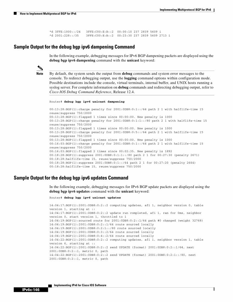
IPv6c-146
Implementing Multiprotocol BGP for IPv6How to Implement Multiprotocol BGP for IPv6
Implementing IPv6 for Cisco IOS Software
*d 3FFE:1000::/24 3FFE:C00:E:B::2 00:00:10 237 2839 5609 i*d 2001:228::/35 3FFE:C00:E:B::2 00:23:30 237 2839 5609 2713 i
Sample Output for the debug bgp ipv6 dampening Command
In the following example, debugging messages for IPv6 BGP dampening packets are displayed using the debug bgp ipv6 dampening command with the unicast keyword:
Note By default, the system sends the output from debug commands and system error messages to the console. To redirect debugging output, use the logging command options within configuration mode. Possible destinations include the console, virtual terminals, internal buffer, and UNIX hosts running a syslog server. For complete information on debug commands and redirecting debugging output, refer to Cisco IOS Debug Command Reference, Release 12.4.
Router# debug bgp ipv6 unicast dampening
00:13:28:BGP(1):charge penalty for 2001:0DB8:0:1::/64 path 2 1 with halflife-time 15 reuse/suppress 750/200000:13:28:BGP(1):flapped 1 times since 00:00:00. New penalty is 100000:13:28:BGP(1):charge penalty for 2001:0DB8:0:1:1::/80 path 2 1 with halflife-time 15 reuse/suppress 750/200000:13:28:BGP(1):flapped 1 times since 00:00:00. New penalty is 100000:13:28:BGP(1):charge penalty for 2001:0DB8:0:5::/64 path 2 1 with halflife-time 15 reuse/suppress 750/200000:13:28:BGP(1):flapped 1 times since 00:00:00. New penalty is 100000:16:03:BGP(1):charge penalty for 2001:0DB8:0:1::/64 path 2 1 with halflife-time 15 reuse/suppress 750/200000:16:03:BGP(1):flapped 2 times since 00:02:35. New penalty is 189200:18:28:BGP(1):suppress 2001:0DB8:0:1:1::/80 path 2 1 for 00:27:30 (penalty 2671)00:18:28:halflife-time 15, reuse/suppress 750/200000:18:28:BGP(1):suppress 2001:0DB8:0:1::/64 path 2 1 for 00:27:20 (penalty 2664)00:18:28:halflife-time 15, reuse/suppress 750/2000
Sample Output for the debug bgp ipv6 updates Command
In the following example, debugging messages for IPv6 BGP update packets are displayed using the debug bgp ipv6 updates command with the unicast keyword:
Router# debug bgp ipv6 unicast updates
14:04:17:BGP(1):2001:0DB8:0:2::2 computing updates, afi 1, neighbor version 0, table version 1, starting at ::14:04:17:BGP(1):2001:0DB8:0:2::2 update run completed, afi 1, ran for 0ms, neighbor version 0, start version 1, throttled to 114:04:19:BGP(1):sourced route for 2001:0DB8:0:2::1/64 path #0 changed (weight 32768)14:04:19:BGP(1):2001:0DB8:0:2::1/64 route sourced locally14:04:19:BGP(1):2001:0DB8:0:2:1::/80 route sourced locally14:04:19:BGP(1):2001:0DB8:0:3::2/64 route sourced locally14:04:19:BGP(1):2001:0DB8:0:4::2/64 route sourced locally14:04:22:BGP(1):2001:0DB8:0:2::2 computing updates, afi 1, neighbor version 1, table version 6, starting at ::14:04:22:BGP(1):2001:0DB8:0:2::2 send UPDATE (format) 2001:0DB8:0:2::1/64, next 2001:0DB8:0:2::1, metric 0, path 14:04:22:BGP(1):2001:0DB8:0:2::2 send UPDATE (format) 2001:0DB8:0:2:1::/80, next 2001:0DB8:0:2::1, metric 0, path
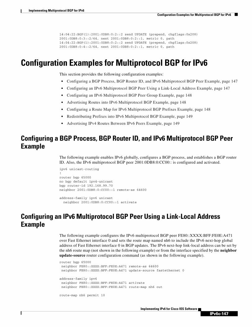
IPv6c-147
Implementing Multiprotocol BGP for IPv6Configuration Examples for Multiprotocol BGP for IPv6
Implementing IPv6 for Cisco IOS Software
14:04:22:BGP(1):2001:0DB8:0:2::2 send UPDATE (prepend, chgflags:0x208) 2001:0DB8:0:3::2/64, next 2001:0DB8:0:2::1, metric 0, path 14:04:22:BGP(1):2001:0DB8:0:2::2 send UPDATE (prepend, chgflags:0x208) 2001:0DB8:0:4::2/64, next 2001:0DB8:0:2::1, metric 0, path
Configuration Examples for Multiprotocol BGP for IPv6This section provides the following configuration examples:
• Configuring a BGP Process, BGP Router ID, and IPv6 Multiprotocol BGP Peer Example, page 147
• Configuring an IPv6 Multiprotocol BGP Peer Using a Link-Local Address Example, page 147
• Configuring an IPv6 Multiprotocol BGP Peer Group Example, page 148
• Advertising Routes into IPv6 Multiprotocol BGP Example, page 148
• Configuring a Route Map for IPv6 Multiprotocol BGP Prefixes Example, page 148
• Redistributing Prefixes into IPv6 Multiprotocol BGP Example, page 149
• Advertising IPv4 Routes Between IPv6 Peers Example, page 149
Configuring a BGP Process, BGP Router ID, and IPv6 Multiprotocol BGP Peer Example
The following example enables IPv6 globally, configures a BGP process, and establishes a BGP router ID. Also, the IPv6 multiprotocol BGP peer 2001:0DB8:0:CC00:: is configured and activated.
ipv6 unicast-routing!router bgp 65000no bgp default ipv4-unicastbgp router-id 192.168.99.70neighbor 2001:0DB8:0:CC00::1 remote-as 64600
address-family ipv6 unicast neighbor 2001:0DB8:0:CC00::1 activate
Configuring an IPv6 Multiprotocol BGP Peer Using a Link-Local Address Example
The following example configures the IPv6 multiprotocol BGP peer FE80::XXXX:BFF:FE0E:A471 over Fast Ethernet interface 0 and sets the route map named nh6 to include the IPv6 next-hop global address of Fast Ethernet interface 0 in BGP updates. The IPv6 next-hop link-local address can be set by the nh6 route map (not shown in the following example) or from the interface specified by the neighbor update-source router configuration command (as shown in the following example).
router bgp 65000neighbor FE80::XXXX:BFF:FE0E:A471 remote-as 64600neighbor FE80::XXXX:BFF:FE0E:A471 update-source fastethernet 0
address-family ipv6neighbor FE80::XXXX:BFF:FE0E:A471 activateneighbor FE80::XXXX:BFF:FE0E:A471 route-map nh6 out
route-map nh6 permit 10

IPv6c-148
Implementing Multiprotocol BGP for IPv6Configuration Examples for Multiprotocol BGP for IPv6
Implementing IPv6 for Cisco IOS Software
match ipv6 address prefix-list ciscoset ipv6 next-hop 2001:0DB8:5y6::1
ipv6 prefix-list cisco permit 2001:0DB8:2Fy2::/48 le 128ipv6 prefix-list cisco deny ::/0
Note If you specify only the global IPv6 next-hop address (the ipv6-address argument) with the set ipv6 next-hop command after specifying the neighbor interface (the interface-type argument) with the neighbor update-source command, the link-local address of the interface specified with the interface-type argument is included as the next hop in the BGP updates. Therefore, only one route map that sets the global IPv6 next-hop address in BGP updates is required for multiple BGP peers that use link-local addresses.
Configuring an IPv6 Multiprotocol BGP Peer Group ExampleThe following example configures the IPv6 multiprotocol BGP peer group named group1:
router bgp 65000no bgp default ipv4-unicastneighbor group1 peer-groupneighbor 2001:0DB8:0:CC00::1 remote-as 64600
address-family ipv6 unicastneighbor group1 activateneighbor 2001:0DB8:0:CC00::1 peer-group group1
Advertising Routes into IPv6 Multiprotocol BGP ExampleThe following example injects the IPv6 network 2001:0DB8::/24 into the IPv6 unicast database of the local router. (BGP checks that a route for the network exists in the IPv6 unicast database of the local router before advertising the network.)
router bgp 65000no bgp default ipv4-unicast
address-family ipv6 unicast network 2001:0DB8::/24
Configuring a Route Map for IPv6 Multiprotocol BGP Prefixes ExampleThe following example configures the route map named rtp to permit IPv6 unicast routes from network 2001:0DB8::/24 if they match the prefix list named cisco:
router bgp 64900no bgp default ipv4-unicastneighbor 2001:0DB8:0:CC00::1 remote-as 64700
address-family ipv6 unicastneighbor 2001:0DB8:0:CC00::1 activateneighbor 2001:0DB8:0:CC00::1 route-map rtp in
ipv6 prefix-list cisco seq 10 permit 2001:0DB8::/24
route-map rtp permit 10match ipv6 address prefix-list cisco

IPv6c-149
Implementing Multiprotocol BGP for IPv6Where to Go Next
Implementing IPv6 for Cisco IOS Software
Redistributing Prefixes into IPv6 Multiprotocol BGP ExampleThe following example redistributes RIP routes into the IPv6 unicast database of the local router:
router bgp 64900no bgp default ipv4-unicastaddress-family ipv6 unicastredistribute rip
Advertising IPv4 Routes Between IPv6 Peers ExampleThe following example advertises IPv4 routes between IPv6 peers when the IPv6 network is connecting two separate IPv4 networks. Peering is configured using IPv6 addresses in the IPv4 address family configuration mode. The inbound route map named rmap sets the next hop because the advertised next hop is likely to be unreachable.
router bgp 65000! neighbor 6peers peer-group neighbor 2001:0DB8:yyyy::2 remote-as 65002 address-family ipv4 neighbor 6peers activate neighbor 6peers soft-reconfiguration inbound neighbor 2001:0DB8:yyyy::2 peer-group 6peers neighbor 2001:0DB8:yyyy::2 route-map rmap in! route-map rmap permit 10 set ip next-hop 10.21.8.10
Where to Go NextIf you want to implement more IPv6 routing protocols, refer to the Implementing RIP for IPv6 or the Implementing IS-IS for IPv6 module.
Additional ReferencesFor additional information related to configuring multiprotocol BGP for IPv6, see the following sections:
• Related Documents, page 150
• Standards, page 150
• MIBs, page 150
• RFCs, page 150
• Technical Assistance, page 151

IPv6c-150
Implementing Multiprotocol BGP for IPv6Additional References
Implementing IPv6 for Cisco IOS Software
Related Documents
Standards
MIBs
RFCs
Related Topic Document Title
BGP configuration tasks “Configuring BGP” chapter in the Cisco IOS IP Configuration Guide, Release 12.4
Multiprotocol BGP configuration tasks “Configuring Multiprotocol BGP Extensions for IP Multicast” chapter in the Cisco IOS IP Configuration Guide, Release 12.4
BGP and multiprotocol BGP commands: complete command syntax, command mode, defaults, usage guidelines, and examples
Cisco IOS IP Command Reference, Volume 2 of 3: Routing Protocols, Release 12.4
IPv6 supported feature list Start Here: Cisco IOS Software Release Specifics for IPv6 Features
IPv6 commands: complete command syntax, command mode, defaults, usage guidelines, and examples
IPv6 for Cisco IOS Command Reference
IPv4 configuration and command reference information
Cisco IOS Release 12.4 Configuration Guides and Command References
Standards Title
No new or modified standards are supported by this feature, and support for existing standards has not been modified by this feature.
—
MIBs MIBs Link
No new or modified MIBs are supported by this feature, and support for existing MIBs has not been modified by this feature.
To locate and download MIBs for selected platforms, Cisco IOS releases, and feature sets, use Cisco MIB Locator found at the following URL:
http://www.cisco.com/go/mibs
RFCs1
1. Not all supported RFCs are listed.
Title
RFC 2545 Use of BGP-4 Multiprotocol Extensions for IPv6 Inter-Domain Routing
RFC 2858 Multiprotocol Extensions for BGP-4

IPv6c-151
Implementing Multiprotocol BGP for IPv6Additional References
Implementing IPv6 for Cisco IOS Software
Technical Assistance
Description Link
The Cisco Technical Support website contains thousands of pages of searchable technical content, including links to products, technologies, solutions, technical tips, and tools. Registered Cisco.com users can log in from this page to access even more content.
http://www.cisco.com/techsupport

IPv6c-152
Implementing Multiprotocol BGP for IPv6Additional References
Implementing IPv6 for Cisco IOS Software

IPv6c-153Implementing IPv6 for Cisco IOS Software
Implementing EIGRP for IPv6
First Published: February 27, 2006Last Updated: February 27, 2006
Customers can configure Enhanced Interior Gateway Routing Protocol (EIGRP) to route IPv6 prefixes. EIGRP IPv4 runs over an IPv4 transport, communicates only with IPv4 peers, and advertises only IPv4 routes, and EIGRP for IPv6 follows the same model. EIGRP for IPv4 and EIGRP for IPv6 are configured and managed separately. However, the configuration of EIGRP for IPv4 and IPv6 is similar and provides operational familiarity and continuity.
Finding Feature Information in This Module
Your Cisco IOS software release may not support all of the features documented in this module. To reach links to specific feature documentation in this module and to see a list of the releases in which each feature is supported, use the “Feature Information for Implementing EIGRP for IPv6” section on page 174.
Finding Support Information for Platforms and Cisco IOS Software Images
Use Cisco Feature Navigator to find information about platform support and Cisco IOS software image support. Access Cisco Feature Navigator at http://www.cisco.com/go/fn. You must have an account on Cisco.com. If you do not have an account or have forgotten your username or password, click Cancel at the login dialog box and follow the instructions that appear.
Contents• Prerequisites for Implementing EIGRP for IPv6, page 153
• Restrictions for Implementing EIGRP for IPv6, page 154
• Information About Implementing EIGRP for IPv6, page 154
• How to Implement EIGRP for IPv6, page 156
• Configuration Examples for Implementing EIGRP for IPv6, page 172
• Where to Go Next, page 173
• Additional References, page 173
Prerequisites for Implementing EIGRP for IPv6This document assumes that you are familiar with EIGRP IPv4.

IPv6c-154
Implementing EIGRP for IPv6Restrictions for Implementing EIGRP for IPv6
Implementing IPv6 for Cisco IOS Software
This document assumes that users have a basic knowledge of IPv6 addressing.
Restrictions for Implementing EIGRP for IPv6This section lists ways in which EIGRP for IPv6 differs from EIGRP IPv4 as well as EIGRP for IPv6 restrictions.
• EIGRP for IPv6 is directly configured on the interfaces over which it runs. This feature allows EIGRP for IPv6 to be configured without the use of a global IPv6 address. There is no network statement in EIGRP for IPv6.
In per-interface configuration at system startup, if EIGRP has been configured on an interface, then the EIGRP protocol may start running before any EIGRP router mode commands have been executed.
• An EIGRP for IPv6 protocol instance requires a router ID before it can start running.
• EIGRP for IPv6 has a shutdown feature. The routing process should be in “no shutdown” mode in order to start running.
• When a user uses passive-interface configuration, EIGRP for IPv6 does not need to be configured on the interface that is made passive.
• EIGRP for IPv6 provides route filtering using the distribute-list prefix-list command. Use of the route-map command is not supported for route filtering with a distribute list.
Information About Implementing EIGRP for IPv6To configure EIGRP for IPv6 in Cisco IOS, you should understand the following concepts:
• Cisco EIGRP for IPv6 Implementation, page 154
Cisco EIGRP for IPv6 ImplementationEIGRP is an enhanced version of the IGRP developed by Cisco. EIGRP uses the same distance vector algorithm and distance information as IGRP. However, the convergence properties and the operating efficiency of EIGRP have improved substantially over IGRP.
The convergence technology is based on research conducted at SRI International and employs an algorithm referred to as the diffusing update algorithm (DUAL). This algorithm guarantees loop-free operation at every instant throughout a route computation and allows all devices involved in a topology change to synchronize at the same time. Routers that are not affected by topology changes are not involved in recomputations. The convergence time with DUAL rivals that of any other existing routing protocol.
EIGRP provides the following features:
• Increased network width—With Routing Information Protocol (RIP), the largest possible width of your network is 15 hops. When EIGRP is enabled, the largest possible width is 224 hops. Because the EIGRP metric is large enough to support thousands of hops, the only barrier to expanding the network is the transport layer hop counter. Cisco works around this problem by incrementing the transport control field only when an IPv4 or an IPv6 packet has traversed 15 routers and the next hop to the destination was learned by way of EIGRP. When a RIP route is being used as the next hop to the destination, the transport control field is incremented as usual.

IPv6c-155
Implementing EIGRP for IPv6Information About Implementing EIGRP for IPv6
Implementing IPv6 for Cisco IOS Software
• Fast convergence—The DUAL algorithm allows routing information to converge as quickly as any other routing protocol.
• Partial updates—EIGRP sends incremental updates when the state of a destination changes, instead of sending the entire contents of the routing table. This feature minimizes the bandwidth required for EIGRP packets.
• Neighbor discovery mechanism—This is a simple hello mechanism used to learn about neighboring routers. It is protocol-independent.
• Arbitrary route summarization.
• Scaling—EIGRP scales to large networks.
• Route filtering—EIGRP for IPv6 provides route filtering using the distribute-list prefix-list command. Use of the route-map command is not supported for route filtering with a distribute list.
EIGRP has the following four basic components:
• Neighbor discovery—Neighbor discovery is the process that routers use to dynamically learn of other routers on their directly attached networks. Routers must also discover when their neighbors become unreachable or inoperative. EIGRP neighbor discovery is achieved with low overhead by periodically sending small hello packets. EIGRP neighbors can also discover a neighbor that has recovered after an outage because the recovered neighbor will send out a hello packet. As long as hello packets are received, the Cisco IOS software can determine that a neighbor is alive and functioning. Once this status is determined, the neighboring routers can exchange routing information.
• Reliable transport protocol—The reliable transport protocol is responsible for guaranteed, ordered delivery of EIGRP packets to all neighbors. It supports intermixed transmission of multicast and unicast packets. Some EIGRP packets must be sent reliably and others need not be. For efficiency, reliability is provided only when necessary. For example, on a multiaccess network that has multicast capabilities (such as Ethernet) it is not necessary to send hello packets reliably to all neighbors individually. Therefore, EIGRP sends a single multicast hello with an indication in the packet informing the receivers that the packet need not be acknowledged. Other types of packets (such as updates) require acknowledgment, which is indicated in the packet. The reliable transport has a provision to send multicast packets quickly when unacknowledged packets are pending. This provision helps to ensure that convergence time remains low in the presence of varying speed links.
• DUAL finite state machine—The DUAL finite state machine embodies the decision process for all route computations. It tracks all routes advertised by all neighbors. DUAL uses several metrics including distance and cost information to select efficient, loop-free paths. When multiple routes to a neighbor exist, DUAL determines which route has the lowest metric (named the feasible distance), and enters this route into the routing table. Other possible routes to this neighbor with larger metrics are received, and DUAL determines the reported distance to this network. The reported distance is defined as the total metric advertised by an upstream neighbor for a path to a destination. DUAL compares the reported distance with the feasible distance, and if the reported distance is less than the feasible distance, DUAL considers the route to be a feasible successor and enters the route into the topology table. The feasible successor route that is reported with the lowest metric becomes the successor route to the current route if the current route fails. To avoid routing loops, DUAL ensures that the reported distance is always less than the feasible distance for a neighbor router to reach the destination network; otherwise, the route to the neighbor may loop back through the local router.
• Protocol-dependent modules—When there are no feasible successors to a route that has failed, but there are neighbors advertising the route, a recomputation must occur. This is the process where DUAL determines a new successor. The amount of time required to recompute the route affects the convergence time. Recomputation is processor-intensive; it is advantageous to avoid unneeded recomputation. When a topology change occurs, DUAL will test for feasible successors. If there are feasible successors, DUAL will use them in order to avoid unnecessary recomputation.

IPv6c-156
Implementing EIGRP for IPv6How to Implement EIGRP for IPv6
Implementing IPv6 for Cisco IOS Software
The protocol-dependent modules are responsible for network layer protocol-specific tasks. An example is the EIGRP module, which is responsible for sending and receiving EIGRP packets that are encapsulated in IPv4 or IPv6. It is also responsible for parsing EIGRP packets and informing DUAL of the new information received. EIGRP asks DUAL to make routing decisions, but the results are stored in the IPv4 or IPv6 routing table. Also, EIGRP is responsible for redistributing routes learned by other IPv4 or IPv6 routing protocols.
How to Implement EIGRP for IPv6The tasks required to implement EIGRP for IPv6 are described in the following sections:
• Enabling EIGRP for IPv6 on an Interface, page 156
• Configuring the Percentage of Link Bandwidth Used, page 158
• Configuring Summary Aggregate Addresses, page 159
• Configuring EIGRP Route Authentication, page 160
• Changing the Next Hop in EIGRP, page 161
• Adjusting the Interval Between Hello Packets in EIGRP for IPv6, page 162
• Adjusting the Hold Time in EIGRP for IPv6, page 163
• Disabling Split Horizon in EIGRP for IPv6, page 164
• Configuring EIGRP Stub Routing for Greater Stability, page 165
• Customizing an EIGRP for IPv6 Routing Process, page 167
• Monitoring and Maintaining EIGRP, page 170
Enabling EIGRP for IPv6 on an InterfacePerform the following task to enable EIGRP for IPv6 on a specified interface. EIGRP for IPv6 is directly configured on the interfaces over which it runs, which allows EIGRP for IPv6 to be configured without the use of a global IPv6 address.
SUMMARY STEPS
1. enable
2. configure terminal
3. ipv6 unicast-routing
4. interface type number
5. ipv6 enable
6. ipv6 eigrp as-number
7. no shutdown
8. ipv6 router eigrp as-number
9. router-id {ip-address | ipv6-address}
10. no shutdown
11. exit
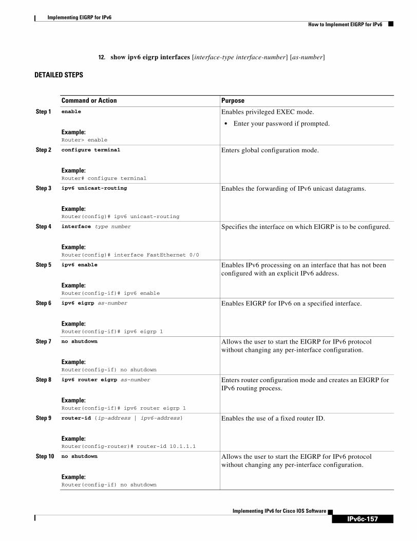
IPv6c-157
Implementing EIGRP for IPv6How to Implement EIGRP for IPv6
Implementing IPv6 for Cisco IOS Software
12. show ipv6 eigrp interfaces [interface-type interface-number] [as-number]
DETAILED STEPS
Command or Action Purpose
Step 1 enable
Example:Router> enable
Enables privileged EXEC mode.
• Enter your password if prompted.
Step 2 configure terminal
Example:Router# configure terminal
Enters global configuration mode.
Step 3 ipv6 unicast-routing
Example:Router(config)# ipv6 unicast-routing
Enables the forwarding of IPv6 unicast datagrams.
Step 4 interface type number
Example:Router(config)# interface FastEthernet 0/0
Specifies the interface on which EIGRP is to be configured.
Step 5 ipv6 enable
Example:Router(config-if)# ipv6 enable
Enables IPv6 processing on an interface that has not been configured with an explicit IPv6 address.
Step 6 ipv6 eigrp as-number
Example:Router(config-if)# ipv6 eigrp 1
Enables EIGRP for IPv6 on a specified interface.
Step 7 no shutdown
Example:Router(config-if) no shutdown
Allows the user to start the EIGRP for IPv6 protocol without changing any per-interface configuration.
Step 8 ipv6 router eigrp as-number
Example:Router(config-if)# ipv6 router eigrp 1
Enters router configuration mode and creates an EIGRP for IPv6 routing process.
Step 9 router-id {ip-address | ipv6-address}
Example:Router(config-router)# router-id 10.1.1.1
Enables the use of a fixed router ID.
Step 10 no shutdown
Example:Router(config-if) no shutdown
Allows the user to start the EIGRP for IPv6 protocol without changing any per-interface configuration.
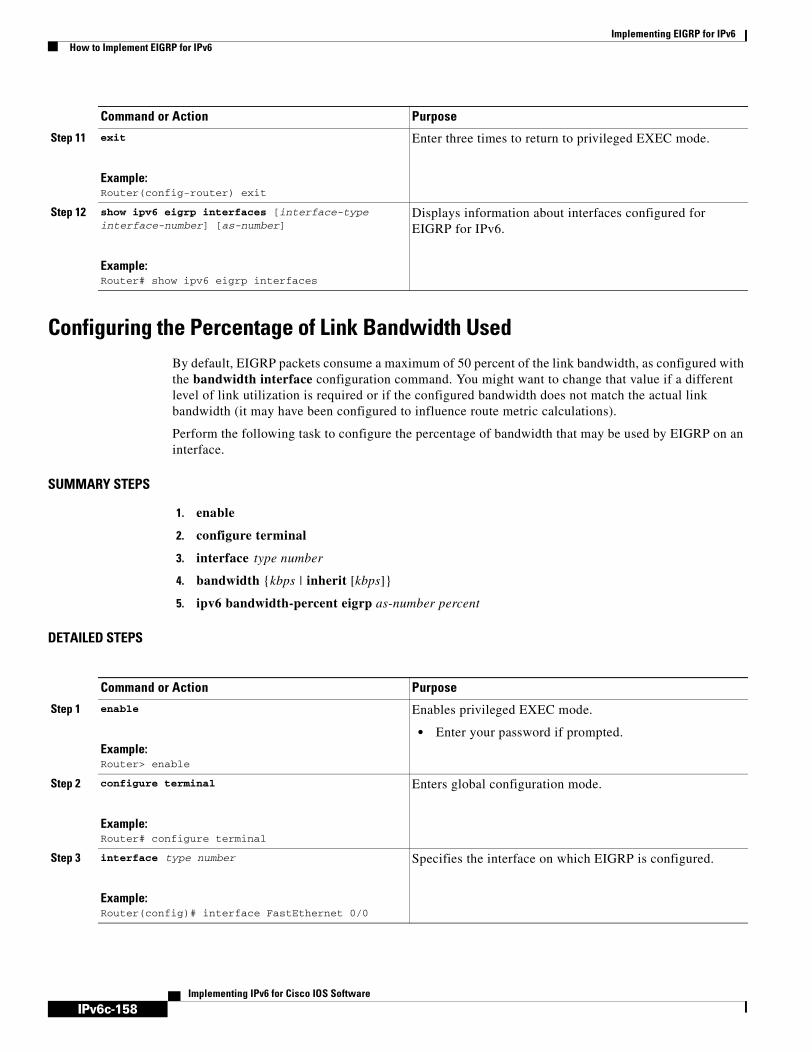
IPv6c-158
Implementing EIGRP for IPv6How to Implement EIGRP for IPv6
Implementing IPv6 for Cisco IOS Software
Configuring the Percentage of Link Bandwidth UsedBy default, EIGRP packets consume a maximum of 50 percent of the link bandwidth, as configured with the bandwidth interface configuration command. You might want to change that value if a different level of link utilization is required or if the configured bandwidth does not match the actual link bandwidth (it may have been configured to influence route metric calculations).
Perform the following task to configure the percentage of bandwidth that may be used by EIGRP on an interface.
SUMMARY STEPS
1. enable
2. configure terminal
3. interface type number
4. bandwidth {kbps | inherit [kbps]}
5. ipv6 bandwidth-percent eigrp as-number percent
DETAILED STEPS
Step 11 exit
Example:Router(config-router) exit
Enter three times to return to privileged EXEC mode.
Step 12 show ipv6 eigrp interfaces [interface-type interface-number] [as-number]
Example:Router# show ipv6 eigrp interfaces
Displays information about interfaces configured for EIGRP for IPv6.
Command or Action Purpose
Command or Action Purpose
Step 1 enable
Example:Router> enable
Enables privileged EXEC mode.
• Enter your password if prompted.
Step 2 configure terminal
Example:Router# configure terminal
Enters global configuration mode.
Step 3 interface type number
Example:Router(config)# interface FastEthernet 0/0
Specifies the interface on which EIGRP is configured.

IPv6c-159
Implementing EIGRP for IPv6How to Implement EIGRP for IPv6
Implementing IPv6 for Cisco IOS Software
Configuring Summary Aggregate AddressesYou can configure a summary aggregate address for a specified interface. If any more specific routes are in the routing table, EIGRP for IPv6 will advertise the summary address out the interface with a metric equal to the minimum of all more specific routes.
SUMMARY STEPS
1. enable
2. configure terminal
3. interface type number
4. ipv6 summary-address eigrp as-number ipv6-address [admin-distance]
DETAILED STEPS
Step 4 bandwidth {kbps | inherit [kbps]}
Example:Router(config-if)# bandwidth 56
Sets and communicates the current bandwidth value for an interface to higher-level protocols.
Step 5 ipv6 bandwidth-percent eigrp as-number percent
Example:Router(config-if)# ipv6 bandwidth-percent eigrp 1 75
Configures the percentage of bandwidth that may be used by EIGRP for IPv6 on an interface
Command or Action Purpose
Command or Action Purpose
Step 1 enable
Example:Router> enable
Enables privileged EXEC mode.
• Enter your password if prompted.
Step 2 configure terminal
Example:Router# configure terminal
Enters global configuration mode.
Step 3 interface type number
Example:Router(config)# interface FastEthernet 0/0
Specifies the interface on which EIGRP is configured.
Step 4 ipv6 summary-address eigrp as-number ipv6-address [admin-distance]
Example:Router(config-if)# ipv6 summary-address eigrp 1 2001:0DB8:0:1::/64
Configures a summary aggregate address for a specified interface.
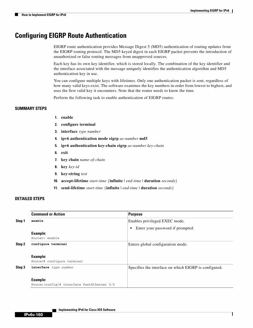
IPv6c-160
Implementing EIGRP for IPv6How to Implement EIGRP for IPv6
Implementing IPv6 for Cisco IOS Software
Configuring EIGRP Route AuthenticationEIGRP route authentication provides Message Digest 5 (MD5) authentication of routing updates from the EIGRP routing protocol. The MD5 keyed digest in each EIGRP packet prevents the introduction of unauthorized or false routing messages from unapproved sources.
Each key has its own key identifier, which is stored locally. The combination of the key identifier and the interface associated with the message uniquely identifies the authentication algorithm and MD5 authentication key in use.
You can configure multiple keys with lifetimes. Only one authentication packet is sent, regardless of how many valid keys exist. The software examines the key numbers in order from lowest to highest, and uses the first valid key it encounters. Note that the router needs to know the time.
Perform the following task to enable authentication of EIGRP routes:
SUMMARY STEPS
1. enable
2. configure terminal
3. interface type number
4. ipv6 authentication mode eigrp as-number md5
5. ipv6 authentication key-chain eigrp as-number key-chain
6. exit
7. key chain name-of-chain
8. key key-id
9. key-string text
10. accept-lifetime start-time {infinite | end-time | duration seconds}
11. send-lifetime start-time {infinite | end-time | duration seconds}
DETAILED STEPS
Command or Action Purpose
Step 1 enable
Example:Router> enable
Enables privileged EXEC mode.
• Enter your password if prompted.
Step 2 configure terminal
Example:Router# configure terminal
Enters global configuration mode.
Step 3 interface type number
Example:Router(config)# interface FastEthernet 0/0
Specifies the interface on which EIGRP is configured.

IPv6c-161
Implementing EIGRP for IPv6How to Implement EIGRP for IPv6
Implementing IPv6 for Cisco IOS Software
Changing the Next Hop in EIGRPEIGRP will, by default, set the IPv6 next-hop value to be itself for routes that it is advertising, even when advertising those routes back out the same interface where it learned them. To change this default, use the following task to instruct EIGRP to use the received next-hop value when advertising these routes.
Step 4 ipv6 authentication mode eigrp as-number md5
Example:Router(config-if)# ipv6 authentication mode eigrp 1 md5
Specify the type of authentication used in EIGRP for IPv6 packets.
Step 5 ipv6 authentication key-chain eigrp as-number key-chain
Example:Router(config-if)# ipv6 authentication key-chain eigrp 1 chain1
Enables authentication of EIGRP for IPv6 packets.
Step 6 exit
Example:Router(config-if)# exit
Exits to global configuration mode.
Step 7 key chain name-of-chain
Example:Router(config)# key chain chain1
Identifies a group of authentication keys. Use the name specified in Step 5.
Step 8 key key-id
Example:Router(config-keychain)# key 1
Identifies an authentication key on a key chain.
Step 9 key-string text
Example:Router(config-keychain-key)# key-string chain 1
Specifies the authentication string for a key.
Step 10 accept-lifetime start-time {infinite | end-time | duration seconds}
Example:Router(config-keychain-key)# accept-lifetime 14:30:00 Jan 10 2006 duration 7200
Sets the time period during which the authentication key on a key chain is received as valid.
Step 11 send-lifetime start-time {infinite | end-time | duration seconds}
Example:Router(config-keychain-key)# send-lifetime 15:00:00 Jan 10 2006 duration 3600
Sets the time period during which an authentication key on a key chain is valid to be sent.
Command or Action Purpose
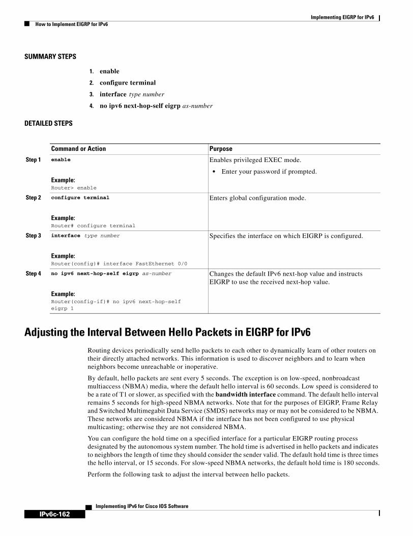
IPv6c-162
Implementing EIGRP for IPv6How to Implement EIGRP for IPv6
Implementing IPv6 for Cisco IOS Software
SUMMARY STEPS
1. enable
2. configure terminal
3. interface type number
4. no ipv6 next-hop-self eigrp as-number
DETAILED STEPS
Adjusting the Interval Between Hello Packets in EIGRP for IPv6Routing devices periodically send hello packets to each other to dynamically learn of other routers on their directly attached networks. This information is used to discover neighbors and to learn when neighbors become unreachable or inoperative.
By default, hello packets are sent every 5 seconds. The exception is on low-speed, nonbroadcast multiaccess (NBMA) media, where the default hello interval is 60 seconds. Low speed is considered to be a rate of T1 or slower, as specified with the bandwidth interface command. The default hello interval remains 5 seconds for high-speed NBMA networks. Note that for the purposes of EIGRP, Frame Relay and Switched Multimegabit Data Service (SMDS) networks may or may not be considered to be NBMA. These networks are considered NBMA if the interface has not been configured to use physical multicasting; otherwise they are not considered NBMA.
You can configure the hold time on a specified interface for a particular EIGRP routing process designated by the autonomous system number. The hold time is advertised in hello packets and indicates to neighbors the length of time they should consider the sender valid. The default hold time is three times the hello interval, or 15 seconds. For slow-speed NBMA networks, the default hold time is 180 seconds.
Perform the following task to adjust the interval between hello packets.
Command or Action Purpose
Step 1 enable
Example:Router> enable
Enables privileged EXEC mode.
• Enter your password if prompted.
Step 2 configure terminal
Example:Router# configure terminal
Enters global configuration mode.
Step 3 interface type number
Example:Router(config)# interface FastEthernet 0/0
Specifies the interface on which EIGRP is configured.
Step 4 no ipv6 next-hop-self eigrp as-number
Example:Router(config-if)# no ipv6 next-hop-self eigrp 1
Changes the default IPv6 next-hop value and instructs EIGRP to use the received next-hop value.

IPv6c-163
Implementing EIGRP for IPv6How to Implement EIGRP for IPv6
Implementing IPv6 for Cisco IOS Software
SUMMARY STEPS
1. enable
2. configure terminal
3. interface type number
4. ipv6 hello-interval eigrp as-number seconds
DETAILED STEPS
Adjusting the Hold Time in EIGRP for IPv6On very congested and large networks, the default hold time might not be sufficient time for all routers to receive hello packets from their neighbors. In this case, you may want to increase the hold time. Perform the following task to adjust the hold time.
SUMMARY STEPS
1. enable
2. configure terminal
3. interface type number
4. ipv6 hold-time eigrp as-number seconds
Command or Action Purpose
Step 1 enable
Example:Router> enable
Enables privileged EXEC mode.
• Enter your password if prompted.
Step 2 configure terminal
Example:Router# configure terminal
Enters global configuration mode.
Step 3 interface type number
Example:Router(config)# interface FastEthernet 0/0
Specifies the interface on which EIGRP is configured.
Step 4 ipv6 hello-interval eigrp as-number seconds
Example:Router(config)# ipv6 hello-interval eigrp 1 10
Configures the hello interval for the EIGRP for IPv6 routing process designated by an autonomous system number.

IPv6c-164
Implementing EIGRP for IPv6How to Implement EIGRP for IPv6
Implementing IPv6 for Cisco IOS Software
DETAILED STEPS
Disabling Split Horizon in EIGRP for IPv6Split horizon controls the sending of EIGRP update and query packets. When split horizon is enabled on an interface, update and query packets are not sent for destinations for which this interface is the next hop. Controlling update and query packets in this manner reduces the possibility of routing loops.
By default, split horizon is enabled on all interfaces.
Split horizon blocks route information from being advertised by a router out of any interface from which that information originated. This behavior usually optimizes communications among multiple routing devices, particularly when links are broken. However, with nonbroadcast networks (such as Frame Relay and SMDS), situations can arise for which this behavior is less than ideal. For these situations, including networks in which you have EIGRP configured, you may want to disable split horizon.
Perform the following task to disable split horizon.
SUMMARY STEPS
1. enable
2. configure terminal
3. interface type number
4. no ipv6 split-horizon eigrp as-number
Command or Action Purpose
Step 1 enable
Example:Router> enable
Enables privileged EXEC mode.
• Enter your password if prompted.
Step 2 configure terminal
Example:Router# configure terminal
Enters global configuration mode.
Step 3 interface type number
Example:Router(config)# interface FastEthernet 0/0
Specifies the interface on which EIGRP is configured.
Step 4 ipv6 hold-time eigrp as-number seconds
Example:Router(config)# ipv6 hold-time eigrp 1 40
Configures the hold time for a particular EIGRP for IPv6 routing process designated by the autonomous system number.
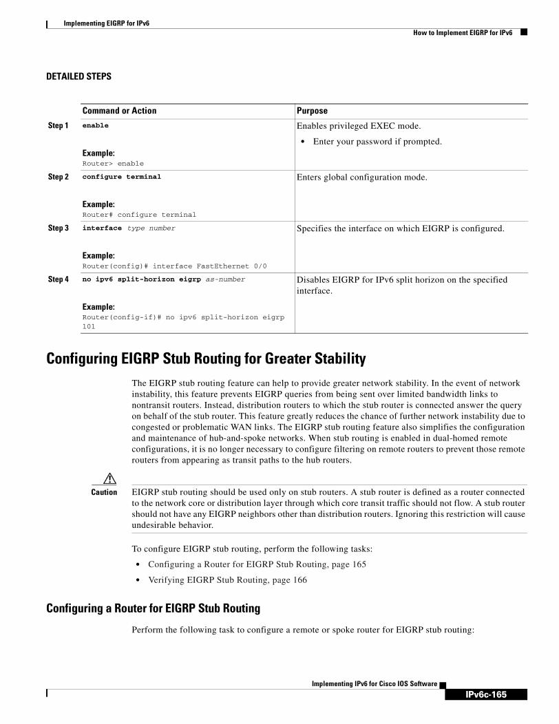
IPv6c-165
Implementing EIGRP for IPv6How to Implement EIGRP for IPv6
Implementing IPv6 for Cisco IOS Software
DETAILED STEPS
Configuring EIGRP Stub Routing for Greater StabilityThe EIGRP stub routing feature can help to provide greater network stability. In the event of network instability, this feature prevents EIGRP queries from being sent over limited bandwidth links to nontransit routers. Instead, distribution routers to which the stub router is connected answer the query on behalf of the stub router. This feature greatly reduces the chance of further network instability due to congested or problematic WAN links. The EIGRP stub routing feature also simplifies the configuration and maintenance of hub-and-spoke networks. When stub routing is enabled in dual-homed remote configurations, it is no longer necessary to configure filtering on remote routers to prevent those remote routers from appearing as transit paths to the hub routers.
Caution EIGRP stub routing should be used only on stub routers. A stub router is defined as a router connected to the network core or distribution layer through which core transit traffic should not flow. A stub router should not have any EIGRP neighbors other than distribution routers. Ignoring this restriction will cause undesirable behavior.
To configure EIGRP stub routing, perform the following tasks:
• Configuring a Router for EIGRP Stub Routing, page 165
• Verifying EIGRP Stub Routing, page 166
Configuring a Router for EIGRP Stub Routing
Perform the following task to configure a remote or spoke router for EIGRP stub routing:
Command or Action Purpose
Step 1 enable
Example:Router> enable
Enables privileged EXEC mode.
• Enter your password if prompted.
Step 2 configure terminal
Example:Router# configure terminal
Enters global configuration mode.
Step 3 interface type number
Example:Router(config)# interface FastEthernet 0/0
Specifies the interface on which EIGRP is configured.
Step 4 no ipv6 split-horizon eigrp as-number
Example:Router(config-if)# no ipv6 split-horizon eigrp 101
Disables EIGRP for IPv6 split horizon on the specified interface.
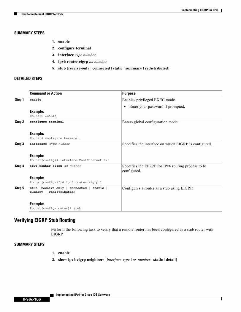
IPv6c-166
Implementing EIGRP for IPv6How to Implement EIGRP for IPv6
Implementing IPv6 for Cisco IOS Software
SUMMARY STEPS
1. enable
2. configure terminal
3. interface type number
4. ipv6 router eigrp as-number
5. stub [receive-only | connected | static | summary | redistributed]
DETAILED STEPS
Verifying EIGRP Stub Routing
Perform the following task to verify that a remote router has been configured as a stub router with EIGRP.
SUMMARY STEPS
1. enable
2. show ipv6 eigrp neighbors [interface-type | as-number | static | detail]
Command or Action Purpose
Step 1 enable
Example:Router> enable
Enables privileged EXEC mode.
• Enter your password if prompted.
Step 2 configure terminal
Example:Router# configure terminal
Enters global configuration mode.
Step 3 interface type number
Example:Router(config)# interface FastEthernet 0/0
Specifies the interface on which EIGRP is configured.
Step 4 ipv6 router eigrp as-number
Example:Router(config-if)# ipv6 router eigrp 1
Specifies the EIGRP for IPv6 routing process to be configured.
Step 5 stub [receive-only | connected | static | summary | redistributed]
Example:Router(config-router)# stub
Configures a router as a stub using EIGRP.
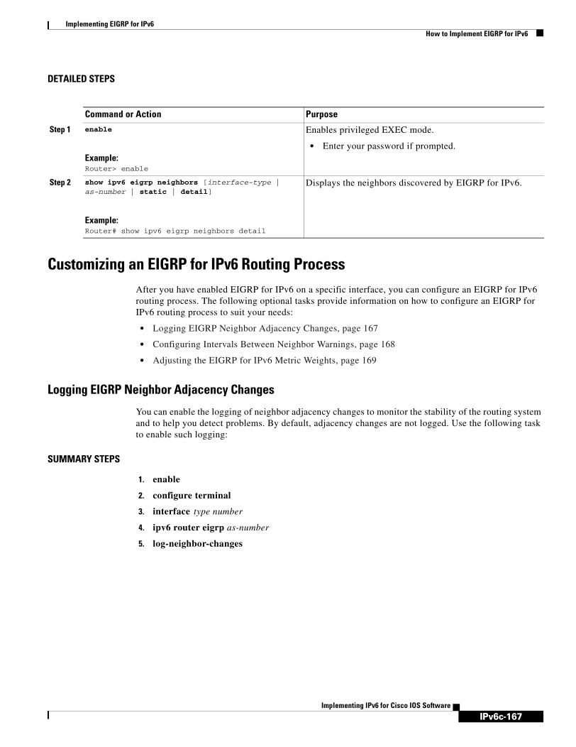
IPv6c-167
Implementing EIGRP for IPv6How to Implement EIGRP for IPv6
Implementing IPv6 for Cisco IOS Software
DETAILED STEPS
Customizing an EIGRP for IPv6 Routing Process After you have enabled EIGRP for IPv6 on a specific interface, you can configure an EIGRP for IPv6 routing process. The following optional tasks provide information on how to configure an EIGRP for IPv6 routing process to suit your needs:
• Logging EIGRP Neighbor Adjacency Changes, page 167
• Configuring Intervals Between Neighbor Warnings, page 168
• Adjusting the EIGRP for IPv6 Metric Weights, page 169
Logging EIGRP Neighbor Adjacency Changes
You can enable the logging of neighbor adjacency changes to monitor the stability of the routing system and to help you detect problems. By default, adjacency changes are not logged. Use the following task to enable such logging:
SUMMARY STEPS
1. enable
2. configure terminal
3. interface type number
4. ipv6 router eigrp as-number
5. log-neighbor-changes
Command or Action Purpose
Step 1 enable
Example:Router> enable
Enables privileged EXEC mode.
• Enter your password if prompted.
Step 2 show ipv6 eigrp neighbors [interface-type | as-number | static | detail]
Example:Router# show ipv6 eigrp neighbors detail
Displays the neighbors discovered by EIGRP for IPv6.

IPv6c-168
Implementing EIGRP for IPv6How to Implement EIGRP for IPv6
Implementing IPv6 for Cisco IOS Software
DETAILED STEPS
Configuring Intervals Between Neighbor Warnings
When neighbor warning messages occur, they are logged by default. Use the following task to configure the interval between neighbor warning messages.
SUMMARY STEPS
1. enable
2. configure terminal
3. interface type number
4. ipv6 router eigrp as-number
5. log-neighbor-warnings [seconds]
Command or Action Purpose
Step 1 enable
Example:Router> enable
Enables privileged EXEC mode.
• Enter your password if prompted.
Step 2 configure terminal
Example:Router# configure terminal
Enters global configuration mode.
Step 3 interface type number
Example:Router(config)# interface FastEthernet 0/0
Enters the interface on which EIGRP is configured.
Step 4 ipv6 router eigrp as-number
Example:Router(config-if)# ipv6 router eigrp 1
Specifies the EIGRP for IPv6 routing process to be configured.
Step 5 log-neighbor-changes
Example:Router(config-router)# log-neighbor-changes
Enables the logging of changes in EIGRP for IPv6 neighbor adjacencies.

IPv6c-169
Implementing EIGRP for IPv6How to Implement EIGRP for IPv6
Implementing IPv6 for Cisco IOS Software
DETAILED STEPS
Adjusting the EIGRP for IPv6 Metric WeightsEIGRP for IPv6 uses the minimum bandwidth on the path to a destination network and the total delay to compute routing metrics. You can use the metric weights command to adjust the default behavior of EIGRP for IPv6EIGRP for IPv6 routing and metric computations. For example, this adjustment allows you to tune system behavior to allow for satellite transmission. EIGRP for IPv6 metric defaults have been carefully selected to provide optimal performance in most networks.
Note Adjusting EIGRP metric weights can dramatically affect network performance. Because of the complexity of this task, we recommend that you do not change the default values without guidance from an experienced network designer.
By default, the EIGRP composite metric is a 32-bit quantity that is a sum of the segment delays and the lowest segment bandwidth (scaled and inverted) for a given route. For a network of homogeneous media, this metric reduces to a hop count. For a network of mixed media (FDDI, Ethernet, and serial lines running from 9600 bits per second to T1 rates), the route with the lowest metric reflects the most desirable path to a destination.
Perform the following task to adjust the EIGRP for IPv6 metric weights:
Command or Action Purpose
Step 1 enable
Example:Router> enable
Enables privileged EXEC mode.
• Enter your password if prompted.
Step 2 configure terminal
Example:Router# configure terminal
Enters global configuration mode.
Step 3 interface type number
Example:Router(config)# interface FastEthernet 0/0
Enters the interface on which EIGRP is configured.
Step 4 ipv6 router eigrp as-number
Example:Router(config-if)# ipv6 router eigrp 1
Specifies the EIGRP for IPv6 routing process to be configured.
Step 5 log-neighbor-warnings [seconds]
Example:Router(config-router)# log-neighbor-warnings 300
Configures the logging intervals of EIGRP neighbor warning messages.

IPv6c-170
Implementing EIGRP for IPv6How to Implement EIGRP for IPv6
Implementing IPv6 for Cisco IOS Software
SUMMARY STEPS
1. enable
2. configure terminal
3. interface type number
4. ipv6 router eigrp as-number
5. metric weights tos k1 k2 k3 k4 k5
DETAILED STEPS
Monitoring and Maintaining EIGRPUse of clear and debug commands helps users monitor and maintain their EIGRP for IPv6 environments. The following tasks provide commands used to monitor and maintain EIGRP for IPv6:
• Deleting Entries from EIGRP for IPv6 Routing Tables, page 170
• Using Debugging Commands to Troubleshoot an EIGRP for IPv6 Environment, page 171
Deleting Entries from EIGRP for IPv6 Routing Tables
Perform the following task to delete entries from EIGRP for IPv6 routing tables.
Command or Action Purpose
Step 1 enable
Example:Router> enable
Enables privileged EXEC mode.
• Enter your password if prompted.
Step 2 configure terminal
Example:Router# configure terminal
Enters global configuration mode.
Step 3 interface type number
Example:Router(config)# interface FastEthernet 0/0
Enters the interface on which EIGRP is configured.
Step 4 ipv6 router eigrp as-number
Example:Router(config-if)# ipv6 router eigrp 1
Specifies the EIGRP for IPv6 routing process to be configured.
Step 5 metric weights tos k1 k2 k3 k4 k5
Example:Router(config-router)# metric weights 0 2 0 2 0 0
Tunes EIGRP metric calculations.

IPv6c-171
Implementing EIGRP for IPv6How to Implement EIGRP for IPv6
Implementing IPv6 for Cisco IOS Software
SUMMARY STEPS
1. enable
2. clear ipv6 eigrp [as-number] [neighbor [ipv6-address | interface-type interface-number]]
DETAILED STEPS
Using Debugging Commands to Troubleshoot an EIGRP for IPv6 Environment
The use of debug commands can provide information users need to help troubleshoot an EIGRP for IPv6 environment. This task shows the commands used to display debugging information in EIGRP for IPv6. Note that the debug commands shown do not have to be used in any particular order and may be used only as needed:
SUMMARY STEPS
1. enable
2. debug eigrp fsm
3. debug eigrp neighbor [siatimer] [static]
4. debug eigrp packet
5. debug eigrp transmit [ack] [build] [detail] [link] [packetize] [peerdown] [sia] [startup] [strange]
6. debug ipv6 eigrp [as-number] [neighbor ipv6-address | notification | summary]
Command or Action Purpose
Step 1 enable
Example:Router> enable
Enables privileged EXEC mode.
• Enter your password if prompted.
Step 2 clear ipv6 eigrp [as-number] [neighbor [ipv6-address | interface-type interface-number]]
Example:Router# clear ipv6 eigrp neighbor 3FEE:12E1:2AC1:EA32
Deletes entries from EIGRP for IPv6 routing tables.

IPv6c-172
Implementing EIGRP for IPv6Configuration Examples for Implementing EIGRP for IPv6
Implementing IPv6 for Cisco IOS Software
DETAILED STEPS
Configuration Examples for Implementing EIGRP for IPv6This section contains the following configuration example:
• Configuring EIGRP to Establish Adjacencies on an Interface, page 172
Configuring EIGRP to Establish Adjacencies on an InterfaceEIGRP for IPv6 is configured directly on the interfaces over which it runs. This example shows the minimal configuration required for EIGRP for IPv6 to send hello packets in order to establish adjacencies on Ethernet 0:
ipv6 unicast-routinginterface e0
ipv6 enable ipv6 eigrp 1
Command or Action Purpose
Step 1 enable
Example:Router> enable
Enables privileged EXEC mode.
• Enter your password if prompted.
Step 2 debug eigrp fsm
Example:Router# debug eigrp fsm
Displays debugging information about EIGRP feasible successor metrics (FSMs).
Step 3 debug eigrp neighbor [siatimer] [static]
Example:Router# debug eigrp neighbor
Displays neighbors discovered by EIGRP for IPv6.
Step 4 debug eigrp packet
Example:Router# debug eigrp packet
Displays debugging information for EIGRP for IPv6 packets.
Step 5 debug eigrp transmit [ack] [build] [detail] [link] [packetize] [peerdown] [sia] [startup] [strange]
Example:Router# debug eigrp transmit
Display transmittal messages sent by EIGRP for IPv6.
Step 6 debug ipv6 eigrp [as-number] [neighbor ipv6-address | notification | summary]
Example:Router# debug ipv6 eigrp
Displays information about the EIGRP for IPv6 protocol.

IPv6c-173
Implementing EIGRP for IPv6Where to Go Next
Implementing IPv6 for Cisco IOS Software
no shutdown!ipv6 router eigrp 1 router-id 10.1.1.1 no shutdown
Where to Go NextIf you want to implement IPv6 interior gateway routing protocols, refer to the “Implementing RIP for IPv6” or “Implementing IS-IS for IPv6” module. To implement exterior gateway routing protocol Border Gateway Protocol (BGP), refer to the Implementing Multiprotocol BGP for IPv6 module.
Additional ReferencesThe following sections provide references related to implementing EIGRP for IPv6.
Related Documents
Standards
Related Topic Document Title
EIGRP for IPv6 commands Cisco IOS IPv6 Command Reference
IPv6 supported feature list Start Here: Cisco IOS Software Release Specifics for IPv6 Features
EIGRP for IPv4 “EIGRP,” Cisco IOS IP Routing Protocols Configuration Guide, Release 12.4
EIGRP for IPv4 commands “EIGRP Commands,” Cisco IOS IP Routing Protocols Command Reference, Release 12.4
Standard Title
No new or modified standards are supported by this feature, and support for existing standards has not been modified by this feature.
—

IPv6c-174
Implementing EIGRP for IPv6Feature Information for Implementing EIGRP for IPv6
Implementing IPv6 for Cisco IOS Software
MIBs
RFCs
Technical Assistance
Feature Information for Implementing EIGRP for IPv6Table 7 lists the release history for this feature.
Not all commands may be available in your Cisco IOS software release. For release information about a specific command, see the command reference documentation.
Cisco IOS software images are specific to a Cisco IOS software release, a feature set, and a platform. Use Cisco Feature Navigator to find information about platform support and Cisco IOS software image support. Access Cisco Feature Navigator at http://www.cisco.com/go/fn. You must have an account on Cisco.com. If you do not have an account or have forgotten your username or password, click Cancel at the login dialog box and follow the instructions that appear.
Note Table 7 lists only the Cisco IOS software release that introduced support for a given feature in a given Cisco IOS software release train. Unless noted otherwise, subsequent releases of that Cisco IOS software release train also support that feature.
MIB MIBs Link
To locate and download MIBs for selected platforms, Cisco IOS releases, and feature sets, use Cisco MIB Locator found at the following URL:
http://www.cisco.com/go/mibs
RFC Title
No new or modified RFCs are supported by this feature, and support for existing RFCs has not been modified by this feature.
—
Description Link
The Cisco Technical Support website contains thousands of pages of searchable technical content, including links to products, technologies, solutions, technical tips, and tools. Registered Cisco.com users can log in from this page to access even more content.
http://www.cisco.com/techsupport

IPv6c-175
Implementing EIGRP for IPv6Feature Information for Implementing EIGRP for IPv6
Implementing IPv6 for Cisco IOS Software
Table 7 Feature Information for EIGRP for IPv6
Feature Name Releases Feature Information
EIGRP Support for IPv6 12.4(6)T Customers can configure EIGRP to route IPv6 prefixes. There is no linkage between EIGRP for IPv4 and EIGRP for IPv6; they are configured and managed separately. However, the configuration of EIGRP for IPv4 and IPv6 is similar and provides operational familiarity and continuity.
The following sections provide information about this feature:
• “Cisco EIGRP for IPv6 Implementation” section on page 154
• “Enabling EIGRP for IPv6 on an Interface” section on page 156
The following commands were introduced or modified by this feature: accept-lifetime, bandwidth (interface), clear ipv6 eigrp, debug eigrp fsm, debug eigrp neighbor, debug eigrp packet, debug eigrp transmit, debug ipv6 eigrp, default-metric (EIGRP), distance (IPv6 EIGRP), distribute-list prefix-list (IPv6 EIGRP), ipv6 authentication key-chain eigrp, ipv6 authentication mode eigrp, ipv6 bandwidth-percent eigrp, ipv6 eigrp, ipv6 hello-interval eigrp, ipv6 hold-time eigrp, ipv6 next-hop-self eigrp, ipv6 router eigrp, ipv6 split-horizon eigrp, ipv6 summary-address eigrp, key chain, key, key-string (authentication), log-neighbor-changes (IPv6 EIGRP), log-neighbor-warnings, maximum-paths (IPv6), metric weights (EIGRP), neighbor (EIGRP), passive-interface (IPv6), redistribute (IPv6), router-id (IPv6), send-lifetime, show ipv6 eigrp interfaces, show ipv6 eigrp neighbors, show ipv6 eigrp topology, show ipv6 eigrp traffic, stub, timers active-time, variance (EIGRP).

IPv6c-176
Implementing EIGRP for IPv6Feature Information for Implementing EIGRP for IPv6
Implementing IPv6 for Cisco IOS Software

IPv6c-177Implementing IPv6 for Cisco IOS Software
Configuring GLBP for IPv6
Gateway Load Balancing Protocol (GLBP) is a First Hop Router Redundancy Protocol (FHRP) that protects data traffic from a failed router or circuit, like Hot Standby Router Protocol (HSRP) and Virtual Router Redundancy Protocol (VRRP), while allowing packet load sharing between a group of redundant routers.
Module History
This module was first published on February 27, 2006, and last updated on February 27, 2006.
Finding Feature Information in This Module
Your Cisco IOS software release may not support all features. To find information about feature support and configuration, use the “Feature Information for GLBP for IPv6” section on page 201.
Contents• Prerequisites for GLBP for IPv6, page 177
• Information About GLBP for IPv6, page 178
• How to Configure GLBP for IPv6, page 181
• Configuration Examples for GLBP for IPv6, page 198
• Additional References, page 200
• Glossary, page 201
• Feature Information for GLBP for IPv6, page 201
Prerequisites for GLBP for IPv6Before configuring GLBP, ensure that the routers can support multiple MAC addresses on the physical interfaces. For each GLBP forwarder to be configured, an additional MAC address is used.
In IPv6, link-local addressing must be disabled on interfaces configured with GLBP.

IPv6c-178
Configuring GLBP for IPv6Information About GLBP for IPv6
Implementing IPv6 for Cisco IOS Software
Information About GLBP for IPv6To configure GLBP, you need to understand the following concepts:
• GLBP Overview, page 178
• GLBP Active Virtual Gateway, page 178
• GLBP Virtual MAC Address Assignment, page 179
• GLBP Virtual Gateway Redundancy, page 180
• GLBP Virtual Forwarder Redundancy, page 180
• GLBP Gateway Priority, page 180
• GLBP Gateway Weighting and Tracking, page 181
• GLBP Benefits, page 181
GLBP OverviewThe Gateway Load Balancing Protocol feature provides automatic router backup for IP or IPv6 hosts configured with a single default gateway on an IEEE 802.3 LAN. Multiple first hop routers on the LAN combine to offer a single virtual first hop IP or IPv6 router while sharing the IP or IPv6 packet forwarding load. Other routers on the LAN may act as redundant GLBP routers that will become active if any of the existing forwarding routers fail.
GLBP performs a similar function for the user as HSRP and VRRP. HSRP and VRRP allow multiple routers to participate in a virtual router group configured with a virtual IP or IPv6 address. One member is elected to be the active router to forward packets sent to the virtual IP or IPv6 address for the group. The other routers in the group are redundant until the active router fails. These standby routers have unused bandwidth that the protocol is not using. Although multiple virtual router groups can be configured for the same set of routers, the hosts must be configured for different default gateways, which results in an extra administrative burden. The advantage of GLBP is that it additionally provides load balancing over multiple routers (gateways) using a single virtual IP or IPv6 address and multiple virtual MAC addresses. The forwarding load is shared among all routers in a GLBP group rather than being handled by a single router while the other routers stand idle. Each host is configured with the same virtual IP or IPv6 address, and all routers in the virtual router group participate in forwarding packets. GLBP members communicate between each other through hello messages sent every 3 seconds to the multicast address 224.0.0.102, User Datagram Protocol (UDP) port 3222 (source and destination).
GLBP Active Virtual GatewayMembers of a GLBP group elect one gateway to be the active virtual gateway (AVG) for that group. Other group members provide backup for the AVG in the event that the AVG becomes unavailable. The function of the AVG is that it assigns a virtual MAC address to each member of the GLBP group. Each gateway assumes responsibility for forwarding packets sent to the virtual MAC address assigned to it by the AVG. These gateways are known as active virtual forwarders (AVFs) for their virtual MAC address.
The AVG is also responsible for answering Address Resolution Protocol (ARP) requests for the virtual IP or IPv6 address. Load sharing is achieved by the AVG replying to the ARP requests with different virtual MAC addresses.

IPv6c-179
Configuring GLBP for IPv6Information About GLBP for IPv6
Implementing IPv6 for Cisco IOS Software
In Figure 21, Router A is the AVG for a GLBP group, and is responsible for the virtual IP address 10.21.8.10. Router A is also an AVF for the virtual MAC address 0007.b400.0101. Router B is a member of the same GLBP group and is designated as the AVF for the virtual MAC address 0007.b400.0102. Client 1 has a default gateway IP address of 10.21.8.10 and a gateway MAC address of 0007.b400.0101. Client 2 shares the same default gateway IP address but receives the gateway MAC address 0007.b400.0102 because Router B is sharing the traffic load with Router A.
Figure 21 GLBP Topology
If Router A becomes unavailable, Client 1 will not lose access to the WAN because Router B will assume responsibility for forwarding packets sent to the virtual MAC address of Router A, and for responding to packets sent to its own virtual MAC address. Router B will also assume the role of the AVG for the entire GLBP group. Communication for the GLBP members continues despite the failure of a router in the GLBP group.
GLBP Virtual MAC Address AssignmentA GLBP group allows up to four virtual MAC addresses per group. The AVG is responsible for assigning the virtual MAC addresses to each member of the group. Other group members request a virtual MAC address after they discover the AVG through hello messages. Gateways are assigned the next MAC address in sequence. A virtual forwarder that is assigned a virtual MAC address by the AVG is known as a primary virtual forwarder. Other members of the GLBP group learn the virtual MAC addresses from hello messages. A virtual forwarder that has learned the virtual MAC address is referred to as a secondary virtual forwarder.
Router AAVG 1AVF 1.1
Router BAVF 1.2
Virtual IP address 10.21.8.10Virtual MAC 0007.b400.0101 Virtual MAC 0007.b400.0102
Default gateway:Gateway MAC:
Client 1Virtual IP address 10.21.8.10Virtual MAC 0007.b400.0101
Client 2Virtual IP address 10.21.8.10Virtual MAC 0007.b400.0102
AVG = active virtual gateway
AVF = active virtual forwarder
7226
4
WAN Link1 WAN Link2

IPv6c-180
Configuring GLBP for IPv6Information About GLBP for IPv6
Implementing IPv6 for Cisco IOS Software
GLBP Virtual Gateway RedundancyGLBP operates virtual gateway redundancy in the same way as HSRP. One gateway is elected as the AVG, another gateway is elected as the standby virtual gateway, and the remaining gateways are placed in a listen state.
If an AVG fails, the standby virtual gateway will assume responsibility for the virtual IP or IPv6 address. A new standby virtual gateway is then elected from the gateways in the listen state.
GLBP Virtual Forwarder RedundancyGLBP virtual forwarder redundancy is similar to virtual gateway redundancy with an AVF. If the AVF fails, one of the secondary virtual forwarders in the listen state assumes responsibility for the virtual MAC address.
The new AVF is also a primary virtual forwarder for a different forwarder number. GLBP migrates hosts away from the old forwarder number using two timers that start as soon as the gateway changes to the active virtual forwarder state. GLBP uses the hello messages to communicate the current state of the timers.
The redirect time is the interval during which the AVG continues to redirect hosts to the old virtual forwarder MAC address. When the redirect time expires, the AVG stops using the old virtual forwarder MAC address in ARP replies, although the virtual forwarder will continue to forward packets that were sent to the old virtual forwarder MAC address.
The secondary hold time is the interval during which the virtual forwarder is valid. When the secondary hold time expires, the virtual forwarder is removed from all gateways in the GLBP group. The expired virtual forwarder number becomes eligible for reassignment by the AVG.
GLBP Gateway PriorityGLBP gateway priority determines the role that each GLBP gateway plays and the results if the AVG fails.
Priority also determines if a GLBP router functions as a backup virtual gateway and the order of ascendancy to becoming an AVG if the current AVG fails. You can configure the priority of each backup virtual gateway with a value of 1 through 255 using the glbp priority command.
In Figure 21, if Router A—the AVG in a LAN topology—fails, an election process takes place to determine which backup virtual gateway should take over. In this example, Router B is the only other member in the group so it will automatically become the new AVG. If another router existed in the same GLBP group with a higher priority, then the router with the higher priority would be elected. If both routers have the same priority, the backup virtual gateway with the higher IP or IPv6 address would be elected to become the active virtual gateway.
By default, the GLBP virtual gateway preemptive scheme is disabled. A backup virtual gateway can become the AVG only if the current AVG fails, regardless of the priorities assigned to the virtual gateways. You can enable the GLBP virtual gateway preemptive scheme using the glbp preempt command. Preemption allows a backup virtual gateway to become the AVG, if the backup virtual gateway is assigned a higher priority than the current AVG.

IPv6c-181
Configuring GLBP for IPv6How to Configure GLBP for IPv6
Implementing IPv6 for Cisco IOS Software
GLBP Gateway Weighting and TrackingGLBP uses a weighting scheme to determine the forwarding capacity of each router in the GLBP group. The weighting assigned to a router in the GLBP group can be used to determine whether it will forward packets and, if so, the proportion of hosts in the LAN for which it will forward packets. Thresholds can be set to disable forwarding when the weighting falls below a certain value. When the weighting rises above another threshold, forwarding is automatically reenabled.
The GLBP group weighting can be automatically adjusted by tracking the state of an interface within the router. If a tracked interface goes down, the GLBP group weighting is reduced by a specified value. Different interfaces can be tracked to decrement the GLBP weighting by varying amounts.
By default, the GLBP virtual forwarder preemptive scheme is enabled with a delay of 30 seconds. A backup virtual forwarder can become the AVF if the current AVF weighting falls below the low weighting threshold for 30 seconds. You can disable the GLBP forwarder preemptive scheme using the no glbp forwarder preempt command or change the delay using the glbp forwarder preempt delay minimum command.
GLBP Benefits
Load Sharing
You can configure GLBP in such a way that traffic from LAN clients can be shared equitably among multiple routers.
Multiple Virtual Routers
GLBP supports up to 1024 virtual routers (GLBP groups) on each physical interface of a router and up to four virtual forwarders per group.
Preemption
The redundancy scheme of GLBP enables you to preempt an active virtual gateway with a higher priority backup virtual gateway that has become available. Forwarder preemption works in a similar way, except that forwarder preemption uses weighting instead of priority and is enabled by default.
Authentication
You can also use the industry-standard Message Digest 5 (MD5) algorithm for improved reliability, security, and protection against GLBP-spoofing software. A router within a GLBP group with a different authentication string than other routers will be ignored by other group members. You can alternatively use a simple text password authentication scheme between GLBP group members to detect configuration errors.
How to Configure GLBP for IPv6Customizing the behavior of GLBP is optional. Be aware that as soon as you enable a GLBP group, that group is operating. It is possible that if you first enable a GLBP group before customizing GLBP, the router could take over control of the group and become the AVG before you have finished customizing the feature. Therefore, if you plan to customize GLBP, it is a good idea to do so before enabling GLBP.
This section contains the following procedures:
• Customizing GLBP, page 182 (optional)

IPv6c-182
Configuring GLBP for IPv6How to Configure GLBP for IPv6
Implementing IPv6 for Cisco IOS Software
• Configuring GLBP Authentication, page 184 (optional)
• Configuring GLBP Weighting Values and Object Tracking, page 192 (optional)
• Enabling and Verifying GLBP, page 194 (required)
• Troubleshooting the Gateway Load Balancing Protocol, page 196 (optional)
Customizing GLBPThis task explains how to customize your GLBP configuration.
SUMMARY STEPS
1. enable
2. configure terminal
3. interface type number
4. ip address ip-address mask [secondary]
or
ipv6 address {ipv6-address/prefix-length | prefix-name ipv6-prefix/prefix-length | autoconfig [default-route]}
5. glbp group timers [msec] hellotime [msec] holdtime
6. glbp group timers redirect redirect timeout
7. glbp group load-balancing [host-dependent | round-robin | weighted]
8. glbp group priority level
9. glbp group preempt [delay minimum seconds]
10. glbp group name redundancy-name
11. exit
DETAILED STEPS
Command or Action Purpose
Step 1 enable
Example:Router> enable
Enables privileged EXEC mode.
• Enter your password if prompted.
Step 2 configure terminal
Example:Router# configure terminal
Enters global configuration mode.
Step 3 interface type number
Example:Router(config)# interface fastethernet 0/0
Specifies an interface type and number, and enters interface configuration mode.

IPv6c-183
Configuring GLBP for IPv6How to Configure GLBP for IPv6
Implementing IPv6 for Cisco IOS Software
Step 4 ip address ip-address mask [secondary]
or
ipv6 address {ipv6-address/prefix-length | prefix-name ipv6-prefix/prefix-length | autoconfig [default-route]}
Example:Router(config-if)# ip address 10.21.8.32 255.255.255.0
or
Example:Router(config-if)# ipv6 address 2001:0DB8:0:7272::72/64
Specifies a primary or secondary IP address for an interface.
or
Configures an IPv6 address based on an IPv6 general prefix and enables IPv6 processing on an interface.
Step 5 glbp group timers [msec] hellotime [msec] holdtime
Example:Router(config-if)# glbp 10 timers 5 18
Configures the interval between successive hello packets sent by the AVG in a GLBP group.
• The holdtime argument specifies the interval in seconds before the virtual gateway and virtual forwarder information in the hello packet is considered invalid.
• The optional msec keyword specifies that the following argument will be expressed in milliseconds, instead of the default seconds.
Step 6 glbp group timers redirect redirect timeout
Example:Router(config-if)# glbp 10 timers redirect 600 7200
Configures the time interval during which the AVG continues to redirect clients to an AVF.
• The timeout argument specifies the interval in seconds before a secondary virtual forwarder becomes invalid.
Step 7 glbp group load-balancing [host-dependent | round-robin | weighted]
Example:Router(config-if)# glbp 10 load-balancing host-dependent
Specifies the method of load balancing used by the GLBP AVG.
Step 8 glbp group priority level
Example:Router(config-if)# glbp 10 priority 254
Sets the priority level of the gateway within a GLBP group.
• The default value is 100.
Step 9 glbp group preempt [delay minimum seconds]
Example:Router(config-if)# glbp 10 preempt delay minimum 60
Configures the router to take over as AVG for a GLBP group if it has a higher priority than the current AVG.
• This command is disabled by default.
• Use the optional delay and minimum keywords and the seconds argument to specify a minimum delay interval in seconds before preemption of the AVG takes place.
Command or Action Purpose

IPv6c-184
Configuring GLBP for IPv6How to Configure GLBP for IPv6
Implementing IPv6 for Cisco IOS Software
Configuring GLBP AuthenticationThe following sections describe configuration tasks for GLBP authentication. The task you perform depends on whether you want to use text authentication, a simple MD5 key string, or MD5 key chains for authentication.
• Configuring GLBP MD5 Authentication Using a Key String, page 185
• Configuring GLBP MD5 Authentication Using a Key Chain, page 187
• Configuring GLBP Text Authentication, page 190
How GLBP MD5 Authentication Works
GLBP MD5 authentication provides greater security than the alternative plain text authentication scheme. MD5 authentication allows each GLBP group member to use a secret key to generate a keyed MD5 hash that is part of the outgoing packet. A keyed hash of an incoming packet is generated and, if the hash within the incoming packet does not match the generated hash, the packet is ignored.
The key for the MD5 hash can either be given directly in the configuration using a key string or supplied indirectly through a key chain.
A router will ignore incoming GLBP packets from routers that do not have the same authentication configuration for a GLBP group. GLBP has three authentication schemes:
• No authentication
• Plain text authentication
• MD5 authentication
GLBP packets will be rejected in any of the following cases:
• The authentication schemes differ on the router and in the incoming packet.
• MD5 digests differ on the router and in the incoming packet.
• Text authentication strings differ on the router and in the incoming packet.
Step 10 glbp group name redundancy-name
Example:Router(config-if)# glbp 10 name abcompany
Enables IP or IPv6 redundancy by assigning a name to the GLBP group.
• The GLBP redundancy client must be configured with the same GLBP group name so the redundancy client and the GLBP group can be connected.
Note This command is for future use. The GLBP redundancy client is not yet available.
Step 11 exit
Example:Router(config-if)# exit
Exits interface configuration mode, and returns the router to global configuration mode.
Command or Action Purpose

IPv6c-185
Configuring GLBP for IPv6How to Configure GLBP for IPv6
Implementing IPv6 for Cisco IOS Software
Configuring GLBP MD5 Authentication Using a Key String
Configuring GLBP MD5 authentication protects the router against spoofing software and uses the industry-standard MD5 algorithm for improved reliability and security. Perform this task to configure GLBP MD5 authentication using a key string.
SUMMARY STEPS
1. enable
2. configure terminal
3. interface type number
4. ip address ip-address mask [secondary]
or
ipv6 address {ipv6-address/prefix-length | prefix-name ipv6-prefix/prefix-length | autoconfig [default-route]}
5. glbp group-number authentication md5 key-string [0 | 7] key
6. glbp group-number ip [ip-address [secondary]]
or
glbp group ipv6 [ipv6-address | autoconfig]
7. Repeat Steps 1 through 6 on each router that will communicate.
8. end
9. show glbp
DETAILED STEPS
Command Purpose
Step 1 enable
Example:Router> enable
Enables privileged EXEC mode.
• Enter your password if prompted.
Step 2 configure terminal
Example:Router# configure terminal
Enters global configuration mode.
Step 3 interface type number
Example:Router(config)# interface Ethernet 0/1
Configures an interface type and enters interface configuration mode.
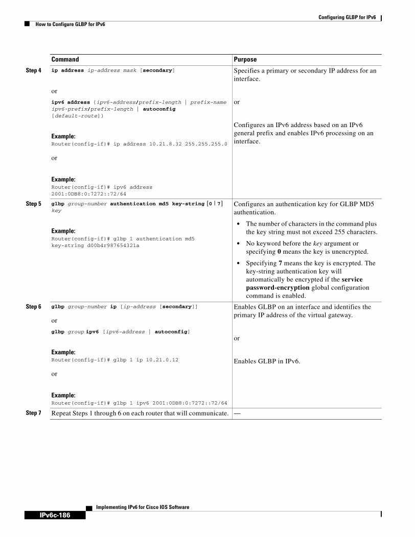
IPv6c-186
Configuring GLBP for IPv6How to Configure GLBP for IPv6
Implementing IPv6 for Cisco IOS Software
Step 4 ip address ip-address mask [secondary]
or
ipv6 address {ipv6-address/prefix-length | prefix-name ipv6-prefix/prefix-length | autoconfig [default-route]}
Example:Router(config-if)# ip address 10.21.8.32 255.255.255.0
or
Example:Router(config-if)# ipv6 address 2001:0DB8:0:7272::72/64
Specifies a primary or secondary IP address for an interface.
or
Configures an IPv6 address based on an IPv6 general prefix and enables IPv6 processing on an interface.
Step 5 glbp group-number authentication md5 key-string [0 | 7] key
Example:Router(config-if)# glbp 1 authentication md5 key-string d00b4r987654321a
Configures an authentication key for GLBP MD5 authentication.
• The number of characters in the command plus the key string must not exceed 255 characters.
• No keyword before the key argument or specifying 0 means the key is unencrypted.
• Specifying 7 means the key is encrypted. The key-string authentication key will automatically be encrypted if the service password-encryption global configuration command is enabled.
Step 6 glbp group-number ip [ip-address [secondary]]
or
glbp group ipv6 [ipv6-address | autoconfig]
Example:Router(config-if)# glbp 1 ip 10.21.0.12
or
Example:Router(config-if)# glbp 1 ipv6 2001:0DB8:0:7272::72/64
Enables GLBP on an interface and identifies the primary IP address of the virtual gateway.
or
Enables GLBP in IPv6.
Step 7 Repeat Steps 1 through 6 on each router that will communicate. —
Command Purpose

IPv6c-187
Configuring GLBP for IPv6How to Configure GLBP for IPv6
Implementing IPv6 for Cisco IOS Software
Configuring GLBP MD5 Authentication Using a Key Chain
Perform this task to configure GLBP MD5 authentication using a key chain. Key chains allow a different key string to be used at different times according to the key chain configuration. GLBP will query the appropriate key chain to obtain the current live key and key ID for the specified key chain.
SUMMARY STEPS
1. enable
2. configure terminal
3. key chain name-of-chain
4. key key-id
5. key-string string
6. exit
7. exit
8. interface type number
9. ip address ip-address mask [secondary]
or
ipv6 address {ipv6-address/prefix-length | prefix-name ipv6-prefix/prefix-length | autoconfig [default-route]}
10. glbp group-number authentication md5 key-chain name-of-chain
11. glbp group-number ip [ip-address [secondary]]
or
glbp group ipv6 [ipv6-address | autoconfig]
12. Repeat Steps 1 through 11 on each router that will communicate.
13. end
14. show glbp
15. show key chain
Step 8 end
Example:Router(config-if)# end
Returns to privileged EXEC mode.
Step 9 show glbp
Example:Router# show glbp
(Optional) Displays GLBP information.
• Use this command to verify your configuration. The key string and authentication type will be displayed if configured.
Command Purpose

IPv6c-188
Configuring GLBP for IPv6How to Configure GLBP for IPv6
Implementing IPv6 for Cisco IOS Software
DETAILED STEPS
Command Purpose
Step 1 enable
Example:Router> enable
Enables privileged EXEC mode.
• Enter your password if prompted.
Step 2 configure terminal
Example:Router# configure terminal
Enters global configuration mode.
Step 3 key chain name-of-chain
Example:Router(config)# key chain glbp2
Enables authentication for routing protocols and identifies a group of authentication keys.
Step 4 key key-id
Example:Router(config-keychain)# key 100
Identifies an authentication key on a key chain.
• The key-id must be a number.
Step 5 key-string string
Example:Router(config-keychain-key)# key-string xmen382
Specifies the authentication string for a key.
• The string can be 1 to 80 uppercase or lowercase alphanumeric characters; the first character cannot be a numeral.
Step 6 exit
Example:Router(config-keychain-key)# exit
Returns to keychain configuration mode.
Step 7 exit
Example:Router(config-keychain)# exit
Returns to global configuration mode.
Step 8 interface type number
Example:Router(config)# interface Ethernet 0/1
Configures an interface type and enters interface configuration mode.

IPv6c-189
Configuring GLBP for IPv6How to Configure GLBP for IPv6
Implementing IPv6 for Cisco IOS Software
Step 9 ip address ip-address mask [secondary]
or
ipv6 address {ipv6-address/prefix-length | prefix-name ipv6-prefix/prefix-length | autoconfig [default-route]}
Example:Router(config-if)# ip address 10.21.8.32 255.255.255.0
or
Example:Router(config-if)# ipv6 address 2001:0DB8:0:7272::72/64
Specifies a primary or secondary IP address for an interface.
or
Configures an IPv6 address based on an IPv6 general prefix and enables IPv6 processing on an interface.
Step 10 glbp group-number authentication md5 key-chain name-of-chain
Example:Router(config-if)# glbp 1 authentication md5 key-chain glbp2
Configures an authentication MD5 key chain for GLBP MD5 authentication.
• The key chain name must match the name specified in Step 3.
Step 11 glbp group-number ip [ip-address [secondary]]
or
glbp group ipv6 [ipv6-address | autoconfig]
Example:Router(config-if)# glbp 1 ip 10.21.0.12
or
Example:Router(config-if)# glbp 1 ipv6 2001:0DB8:0:7272::72/64
Enables GLBP on an interface and identifies the primary IP address of the virtual gateway.
or
Enables GLBP in IPv6.
Step 12 Repeat Steps 1 through 11 on each router that will communicate.
—
Step 13 end
Example:Router(config-if)# end
Returns to privileged EXEC mode.
Command Purpose

IPv6c-190
Configuring GLBP for IPv6How to Configure GLBP for IPv6
Implementing IPv6 for Cisco IOS Software
Configuring GLBP Text Authentication
Perform this task to configure GLBP text authentication. This method of authentication provides minimal security. Use MD5 authentication if security is required.
SUMMARY STEPS
1. enable
2. configure terminal
3. interface type number
4. ip address ip-address mask [secondary]
or
ipv6 address {ipv6-address/prefix-length | prefix-name ipv6-prefix/prefix-length | autoconfig [default-route]}
5. glbp group-number authentication text string
6. glbp group-number ip [ip-address [secondary]]
or
glbp group ipv6 [ipv6-address | autoconfig]
7. Repeat Steps 1 through 6 on each router that will communicate.
8. end
9. show glbp
Step 14 show glbp
Example:Router# show glbp
(Optional) Displays GLBP information.
• Use this command to verify your configuration. The key chain and authentication type will be displayed if configured.
Step 15 show key chain
Example:Router# show key chain
(Optional) Displays authentication key information.
Command Purpose

IPv6c-191
Configuring GLBP for IPv6How to Configure GLBP for IPv6
Implementing IPv6 for Cisco IOS Software
DETAILED STEPS
Command Purpose
Step 1 enable
Example:Router> enable
Enables privileged EXEC mode.
• Enter your password if prompted.
Step 2 configure terminal
Example:Router# configure terminal
Enters global configuration mode.
Step 3 interface type number
Example:Router(config)# interface Ethernet 0/1
Configures an interface type and enters interface configuration mode.
Step 4 ip address ip-address mask [secondary]
or
ipv6 address {ipv6-address/prefix-length | prefix-name ipv6-prefix/prefix-length | autoconfig [default-route]}
Example:Router(config-if)# ip address 10.21.8.32 255.255.255.0
or
Example:Router(config-if)# ipv6 address 2001:0DB8:0:7272::72/64
Specifies a primary or secondary IP address for an interface.
or
Configures an IPv6 address based on an IPv6 general prefix and enables IPv6 processing on an interface.
Step 5 glbp group-number authentication text string
Example:Router(config-if)# glbp 10 authentication text stringxyz
Authenticates GLBP packets received from other routers in the group.
• If you configure authentication, all routers within the GLBP group must use the same authentication string.
Step 6 glbp group-number ip [ip-address [secondary]]
or
glbp group ipv6 [ipv6-address | autoconfig]
Example:Router(config-if)# glbp 1 ip 10.21.0.12
or
Example:Router(config-if)# glbp 1 ipv6 2001:0DB8:0:7272::72/64
Enables GLBP on an interface and identifies the primary IP address of the virtual gateway.
or
Activates GLBP in IPv6.
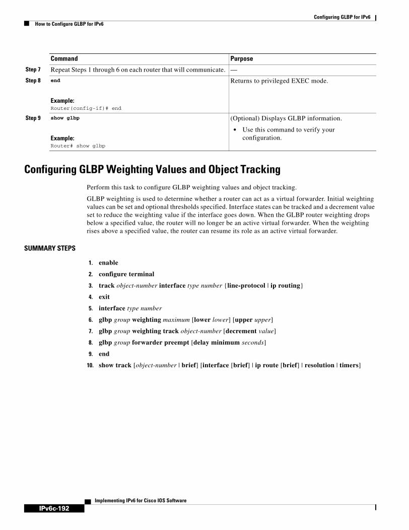
IPv6c-192
Configuring GLBP for IPv6How to Configure GLBP for IPv6
Implementing IPv6 for Cisco IOS Software
Configuring GLBP Weighting Values and Object TrackingPerform this task to configure GLBP weighting values and object tracking.
GLBP weighting is used to determine whether a router can act as a virtual forwarder. Initial weighting values can be set and optional thresholds specified. Interface states can be tracked and a decrement value set to reduce the weighting value if the interface goes down. When the GLBP router weighting drops below a specified value, the router will no longer be an active virtual forwarder. When the weighting rises above a specified value, the router can resume its role as an active virtual forwarder.
SUMMARY STEPS
1. enable
2. configure terminal
3. track object-number interface type number {line-protocol | ip routing}
4. exit
5. interface type number
6. glbp group weighting maximum [lower lower] [upper upper]
7. glbp group weighting track object-number [decrement value]
8. glbp group forwarder preempt [delay minimum seconds]
9. end
10. show track [object-number | brief] [interface [brief] | ip route [brief] | resolution | timers]
Step 7 Repeat Steps 1 through 6 on each router that will communicate. —
Step 8 end
Example:Router(config-if)# end
Returns to privileged EXEC mode.
Step 9 show glbp
Example:Router# show glbp
(Optional) Displays GLBP information.
• Use this command to verify your configuration.
Command Purpose

IPv6c-193
Configuring GLBP for IPv6How to Configure GLBP for IPv6
Implementing IPv6 for Cisco IOS Software
DETAILED STEPS
Command or Action Purpose
Step 1 enable
Example:Router> enable
Enables privileged EXEC mode.
• Enter your password if prompted.
Step 2 configure terminal
Example:Router# configure terminal
Enters global configuration mode.
Step 3 track object-number interface type number {line-protocol | ip routing}
Example:Router(config)# track 2 interface POS 6/0 ip routing
Configures an interface to be tracked where changes in the state of the interface affect the weighting of a GLBP gateway, and enters tracking configuration mode.
• This command configures the interface and corresponding object number to be used with the glbp weighting track command.
• The line-protocol keyword tracks whether the interface is up. The ip routing keywords also check that IP or IPv6 routing is enabled on the interface, and an IP or IPv6 address is configured.
Step 4 exit
Example:Router(config-track)# exit
Returns to global configuration mode.
Step 5 interface type number
Example:Router(config)# interface fastethernet 0/0
Enters interface configuration mode.
Step 6 glbp group weighting maximum [lower lower] [upper upper]
Example:Router(config-if)# glbp 10 weighting 110 lower 95 upper 105
Specifies the initial weighting value, and the upper and lower thresholds, for a GLBP gateway.
Step 7 glbp group weighting track object-number [decrement value]
Example:Router(config-if)# glbp 10 weighting track 2 decrement 5
Specifies an object to be tracked that affects the weighting of a GLBP gateway.
• The value argument specifies a reduction in the weighting of a GLBP gateway when a tracked object fails.
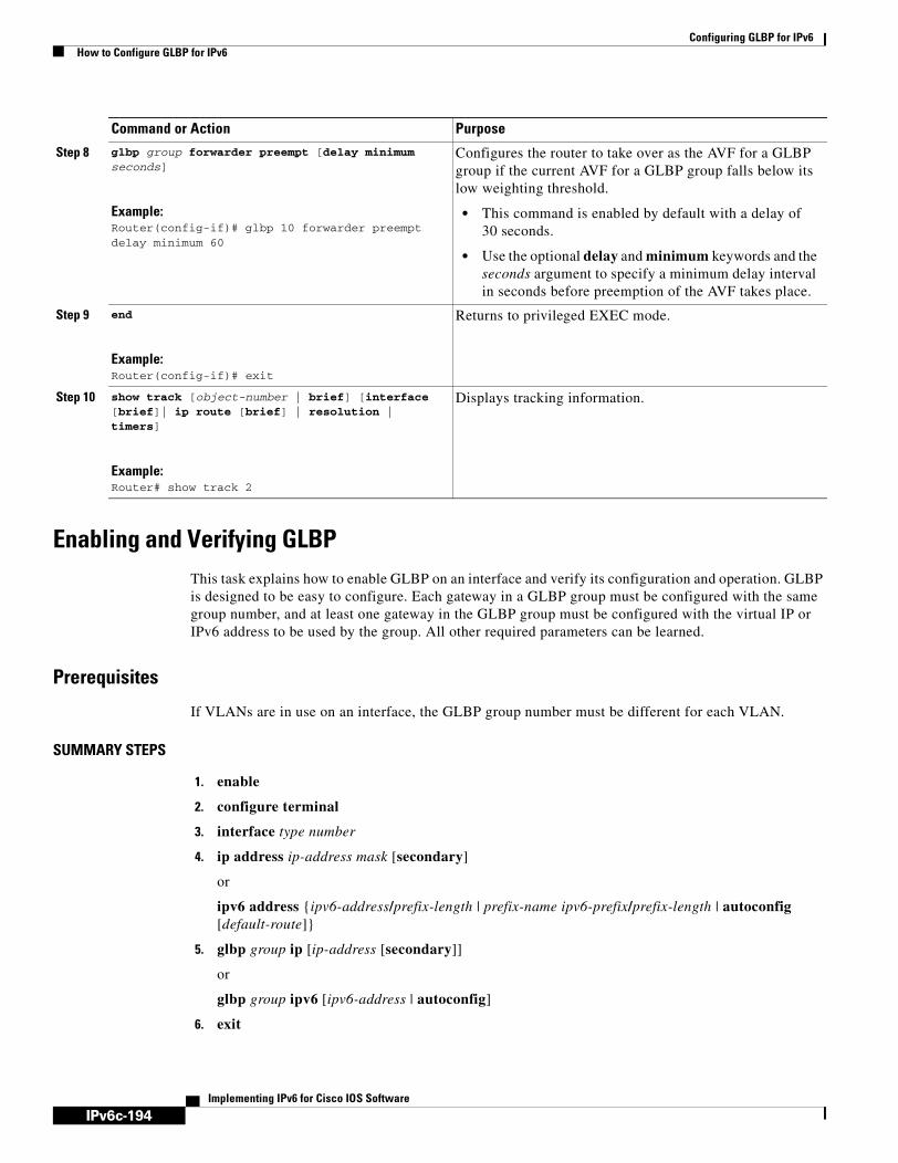
IPv6c-194
Configuring GLBP for IPv6How to Configure GLBP for IPv6
Implementing IPv6 for Cisco IOS Software
Enabling and Verifying GLBPThis task explains how to enable GLBP on an interface and verify its configuration and operation. GLBP is designed to be easy to configure. Each gateway in a GLBP group must be configured with the same group number, and at least one gateway in the GLBP group must be configured with the virtual IP or IPv6 address to be used by the group. All other required parameters can be learned.
Prerequisites
If VLANs are in use on an interface, the GLBP group number must be different for each VLAN.
SUMMARY STEPS
1. enable
2. configure terminal
3. interface type number
4. ip address ip-address mask [secondary]
or
ipv6 address {ipv6-address/prefix-length | prefix-name ipv6-prefix/prefix-length | autoconfig [default-route]}
5. glbp group ip [ip-address [secondary]]
or
glbp group ipv6 [ipv6-address | autoconfig]
6. exit
Step 8 glbp group forwarder preempt [delay minimum seconds]
Example:Router(config-if)# glbp 10 forwarder preempt delay minimum 60
Configures the router to take over as the AVF for a GLBP group if the current AVF for a GLBP group falls below its low weighting threshold.
• This command is enabled by default with a delay of 30 seconds.
• Use the optional delay and minimum keywords and the seconds argument to specify a minimum delay interval in seconds before preemption of the AVF takes place.
Step 9 end
Example:Router(config-if)# exit
Returns to privileged EXEC mode.
Step 10 show track [object-number | brief] [interface [brief]| ip route [brief] | resolution | timers]
Example:Router# show track 2
Displays tracking information.
Command or Action Purpose

IPv6c-195
Configuring GLBP for IPv6How to Configure GLBP for IPv6
Implementing IPv6 for Cisco IOS Software
7. show glbp [interface-type interface-number] [group] [state] [brief]
DETAILED STEPS
Command or Action Purpose
Step 1 enable
Example:Router> enable
Enables privileged EXEC mode.
• Enter your password if prompted.
Step 2 configure terminal
Example:Router# configure terminal
Enters global configuration mode.
Step 3 interface type number
Example:Router(config)# interface fastethernet 0/0
Specifies an interface type and number, and enters interface configuration mode.
Step 4 ip address ip-address mask [secondary]
or
ipv6 address {ipv6-address/prefix-length | prefix-name ipv6-prefix/prefix-length | autoconfig [default-route]}
Example:Router(config-if)# ip address 10.21.8.32 255.255.255.0
or
Example:Router(config-if)# ipv6 address 2001:0DB8:0:7272::72/64
Specifies a primary or secondary IP address for an interface.
or
Configures an IPv6 address based on an IPv6 general prefix and enables IPv6 processing on an interface.
Step 5 glbp group-number ip [ip-address [secondary]]
or
glbp group ipv6 [ipv6-address | autoconfig]
Example:Router(config-if)# glbp 1 ip 10.21.0.12
or
Example:Router(config-if)# glbp 1 ipv6 2001:0DB8:0:7272::72/64
Enables GLBP on an interface and identifies the primary IP address of the virtual gateway.
or
Enables GLBP in IPv6.

IPv6c-196
Configuring GLBP for IPv6How to Configure GLBP for IPv6
Implementing IPv6 for Cisco IOS Software
Examples
In the following example, output information is displayed about the status of the GLBP group, named 10, on the router:
Router# show glbp 10
FastEthernet0/0 - Group 10 State is Active 2 state changes, last state change 23:50:33 Virtual IP address is 10.21.8.10 Hello time 5 sec, hold time 18 sec Next hello sent in 4.300 secs Redirect time 600 sec, forwarder time-out 7200 sec Authentication text "stringabc" Preemption enabled, min delay 60 sec Active is local Standby is unknown Priority 254 (configured) Weighting 105 (configured 110), thresholds: lower 95, upper 105 Track object 2 state Down decrement 5 Load balancing: host-dependent There is 1 forwarder (1 active) Forwarder 1 State is Active 1 state change, last state change 23:50:15 MAC address is 0007.b400.0101 (default) Owner ID is 0005.0050.6c08 Redirection enabled Preemption enabled, min delay 60 sec Active is local, weighting 105
Troubleshooting the Gateway Load Balancing ProtocolThe Gateway Load Balancing Protocol feature introduces five privileged EXEC mode commands to enable diagnostic output concerning various events relating to the operation of GLBP to be displayed on a console. The debug condition glbp, debug glbp errors, debug glbp events, debug glbp packets, and debug glbp terse commands are intended only for troubleshooting purposes because the volume of output generated by the software can result in severe performance degradation on the router. Perform this task to minimize the impact of using the debug glbp commands.
Step 6 exit
Example:Router(config-if)# exit
Exits interface configuration mode, and returns the router to global configuration mode.
Step 7 show glbp [interface-type interface-number] [group] [state] [brief]
Example:Router(config)# show glbp 10
(Optional) Displays information about GLBP groups on a router.
• Use the optional brief keyword to display a single line of information about each virtual gateway or virtual forwarder.
• See the display output for this command in the “Examples” section of this task.
Command or Action Purpose

IPv6c-197
Configuring GLBP for IPv6How to Configure GLBP for IPv6
Implementing IPv6 for Cisco IOS Software
This procedure will minimize the load on the router created by the debug condition glbp or debug glbp command because the console port will no longer generate character-by-character processor interrupts. If you cannot connect to a console directly, you can run this procedure via a terminal server. If you must break the Telnet connection, however, you may not be able to reconnect because the router may be unable to respond due to the processor load of generating the debugging output.
Prerequisites
This task requires a router running GLBP to be attached directly to a console.
SUMMARY STEPS
1. enable
2. configure terminal
3. no logging console
4. Use Telnet to access a router port and repeat Steps 1 and 2.
5. end
6. terminal monitor
7. debug condition glbp interface-type interface-number group [forwarder]
8. terminal no monitor
DETAILED STEPS
Command or Action Purpose
Step 1 enable
Example:Router> enable
Enables privileged EXEC mode.
• Enter your password if prompted.
Step 2 configure terminal
Example:Router# configure terminal
Enters global configuration mode.
Step 3 no logging console
Example:Router(config)# no logging console
Disables all logging to the console terminal.
• To reenable logging to the console, use the logging console command in global configuration mode.
Step 4 Use Telnet to access a router port and repeat Steps 1 and 2.
Enters global configuration mode in a recursive Telnet session, which allows the output to be redirected away from the console port.
Step 5 end
Example:Router(config)# end
Exits to privileged EXEC mode.

IPv6c-198
Configuring GLBP for IPv6Configuration Examples for GLBP for IPv6
Implementing IPv6 for Cisco IOS Software
Configuration Examples for GLBP for IPv6This section contains the following configuration examples:
• Customizing GLBP Configuration: Example, page 198
• GLBP MD5 Authentication Using Key Strings: Example, page 198
• GLBP MD5 Authentication Using Key Chains: Example, page 199
• GLBP Text Authentication: Example, page 199
• GLBP Weighting: Example, page 199
• Enabling GLBP Configuration: Example, page 199
Customizing GLBP Configuration: ExampleIn the following example, Router A, shown in Figure 1, is configured with a number of GLBP commands:
interface fastethernet 0/0 ip address 10.21.8.32 255.255.255.0glbp 10 timers 5 18
glbp 10 timers redirect 600 7200glbp 10 load-balancing host-dependentglbp 10 priority 254glbp 10 preempt delay minimum 60
GLBP MD5 Authentication Using Key Strings: Example The following example configures GLBP MD5 authentication using a key string:
Step 6 terminal monitor
Example:Router# terminal monitor
Enables logging output on the virtual terminal.
Step 7 debug condition glbp interface-type interface-number group [forwarder]
Example:Router# debug condition glbp fastethernet 0/0 10 1
Displays debugging messages about GLBP conditions.
• Try to enter only specific debug condition glbp or debug glbp commands to isolate the output to a certain subcomponent and minimize the load on the processor. Use appropriate arguments and keywords to generate more detailed debug information on specified subcomponents.
• Enter the specific no debug condition glbp or no debug glbp command when you are finished.
Step 8 terminal no monitor
Example:Router# terminal no monitor
Disables logging on the virtual terminal.
Command or Action Purpose

IPv6c-199
Configuring GLBP for IPv6Configuration Examples for GLBP for IPv6
Implementing IPv6 for Cisco IOS Software
!interface Ethernet 0/1ip address 10.0.0.1 255.255.255.0glbp 2 authentication md5 key-string ThisStringIsTheSecretKeyglbp 2 ip 10.0.0.10
GLBP MD5 Authentication Using Key Chains: Example In the following example, GLBP queries the key chain “AuthenticateGLBP” to obtain the current live key and key ID for the specified key chain:
key chain AuthenticateGLBPkey 1key-string ThisIsASecretKey
interface Ethernet 0/1ip address 10.0.0.1 255.255.255.0glbp 2 authentication md5 key-chain AuthenticateGLBPglbp 2 ip 10.0.0.10
GLBP Text Authentication: Example The following example configures GLBP text authentication using a text string:
interface fastethernet 0/0 ip address 10.21.8.32 255.255.255.0glbp 10 authentication text stringxyzglbp 10 ip 10.21.8.10
GLBP Weighting: ExampleIn the following example, Router A, shown in Figure 1, is configured to track the IP routing state of the POS interfaces 5/0 and 6/0, an initial GLBP weighting with upper and lower thresholds is set, and a weighting decrement value of 10 is set. If POS interfaces 5/0 and 6/0 go down, the weighting value of the router is reduced.
track 1 interface POS 5/0 ip routingtrack 2 interface POS 6/0 ip routinginterface fastethernet 0/0glpb 10 weighting 110 lower 95 upper 105
glbp 10 weighting track 1 decrement 10 glbp 10 weighting track 2 decrement 10glbp 10 forwarder preempt delay minimum 60
Enabling GLBP Configuration: ExampleIn the following example, Router A, shown in Figure 1, is configured to enable GLBP, and the virtual IP address of 10.21.8.10 is specified for GLBP group 10:
interface fastethernet 0/0 ip address 10.21.8.32 255.255.255.0 glbp 10 ip 10.21.8.10

IPv6c-200
Configuring GLBP for IPv6Additional References
Implementing IPv6 for Cisco IOS Software
Additional ReferencesThe following sections provide references related to configuring GLBP for IPv6.
Related Documents
Standards
MIBs
RFCs
Related Topic Document Title
GLBP commands: complete command syntax, command mode, command history, defaults, usage guidelines, and examples
Cisco IOS IP Application Services Command Reference, Release 12.4
Key chains and key management commands: complete command syntax, command mode, command history, defaults, usage guidelines, and examples
Cisco IOS IP Routing Command Reference, Release 12.4
IPv6 commands: complete command syntax, command mode, command history, defaults, usage guidelines, and examples
Cisco IOS IPv6 Command Reference, Release 12.4
Object Tracking “ Configuring Enhanced Object Tracking” configuration module
VRRP “Configuring VRRP” configuration module
HSRP “Configuring HSRP” configuration module
Standards Title
No new or modified standards are supported by this feature, and support for existing standards has not been modified by this feature.
—
MIBs MIBs Link
No new MIBs are supported by this feature, and support for existing MIBs has not been modified by this feature.
To locate and download MIBs for selected platforms, Cisco IOS releases, and feature sets, use Cisco MIB Locator found at the following URL:
http://www.cisco.com/go/mibs
RFCs Title
No new or modified RFCs are supported by this feature, and support for existing RFCs has not been modified by this feature.
—

IPv6c-201
Configuring GLBP for IPv6Glossary
Implementing IPv6 for Cisco IOS Software
Technical Assistance
GlossaryAVF—active virtual forwarder. One virtual forwarder within a GLBP group is elected as active virtual forwarder for a specified virtual MAC address, and is responsible for forwarding packets sent to that MAC address. Multiple active virtual forwarders can exist for each GLBP group.
AVG—active virtual gateway. One virtual gateway within a GLBP group is elected as the active virtual gateway, and is responsible for the operation of the protocol.
GLBP gateway—Gateway Load Balancing Protocol gateway. A router or gateway running GLBP. Each GLBP gateway may participate in one or more GLBP groups.
GLBP group—Gateway Load Balancing Protocol group. One or more GLBP gateways configured with the same GLBP group number on connected Ethernet interfaces.
vIP—virtual IP address. An IPv4 address. There must be only one virtual IP address for each configured GLBP group. The virtual IP address must be configured on at least one GLBP group member. Other GLBP group members can learn the virtual IP address from hello messages.
Note Refer to the Internetworking Terms and Acronyms for terms not included in this glossary.
Feature Information for GLBP for IPv6Table 8 lists the features in this module and provides links to specific configuration information. Only features that were introduced or modified in Cisco IOS Release 12.2(1) or Cisco IOS Releases 12.2(14)S or a later release appear in the table.
Not all commands may be available in your Cisco IOS software release. For details on when support for a specific command was introduced, see the command reference documentation.
Cisco IOS software images are specific to a Cisco IOS software release, a feature set, and a platform. Use Cisco Feature Navigator to find information about platform support and Cisco IOS software image support. Access Cisco Feature Navigator at http://www.cisco.com/go/fn. You must have an account on Cisco.com. If you do not have an account or have forgotten your username or password, click Cancel at the login dialog box and follow the instructions that appear.
Description Link
The Cisco Technical Support website contains thousands of pages of searchable technical content, including links to products, technologies, solutions, technical tips, and tools. Registered Cisco.com users can log in from this page to access even more content.
http://www.cisco.com/techsupport

IPv6c-202
Configuring GLBP for IPv6Feature Information for GLBP for IPv6
Implementing IPv6 for Cisco IOS Software
Copyright © 2005 - 2006 Cisco Systems, Inc. All rights reserved.This module first published February 27, 2006. Last updated February 27, 2006
Table 8 Feature Information
Feature Name Releases Feature Configuration Information
Gateway Load Balancing Protocol 12.2(14)S 12.2(15)T
GLBP protects data traffic from a failed router or circuit, like HSRP and VRRP, while allowing packet load sharing between a group of redundant routers.
All sections in this configuration module provide information about this feature.
GLBP MD5 Authentication 12.2(18)S12.3(2)T
MD5 authentication provides greater security than the alternative plain text authentication scheme. MD5 authentication allows each GLBP group member to use a secret key to generate a keyed MD5 hash that is part of the outgoing packet. A keyed hash of an incoming packet is generated and, if the hash within the incoming packet does not match the generated hash, the packet is ignored.
The following section provides information about this feature:
• Configuring GLBP Authentication, page 184
The following commands were modified by this feature: glbp authentication and show glbp.
FHRP—GLBP Support for IPv6 12.4(6)T Support for IPv6 was added. All sections in this configuration module provide information about this feature.
The following command was added by this feature: glbp ipv6. The following command was modified by this feature: show glbp.
CCSP, CCVP, the Cisco Square Bridge logo, Follow Me Browsing, and StackWise are trademarks of Cisco Systems, Inc.; Changing the Way We Work, Live, Play, and Learn, and iQuick Study are service marks of Cisco Systems, Inc.; and Access Registrar, Aironet, BPX, Catalyst, CCDA, CCDP, CCIE, CCIP, CCNA, CCNP, Cisco, the Cisco Certified Internetwork Expert logo, Cisco IOS, Cisco Press, Cisco Systems, Cisco Systems Capital, the Cisco Systems logo, Cisco Unity, Enterprise/Solver, EtherChannel, EtherFast, EtherSwitch, Fast Step, FormShare, GigaDrive, GigaStack, HomeLink, Internet Quotient, IOS, IP/TV, iQ Expertise, the iQ logo, iQ Net Readiness Scorecard, LightStream, Linksys, MeetingPlace, MGX, the Networkers logo, Networking Academy, Network Registrar, Packet, PIX, Post-Routing, Pre-Routing, ProConnect, RateMUX, ScriptShare, SlideCast, SMARTnet, The Fastest Way to Increase Your Internet Quotient, and TransPath are registered trademarks of Cisco Systems, Inc. and/or its affiliates in the United States and certain other countries.
All other trademarks mentioned in this document or Website are the property of their respective owners. The use of the word partner does not imply a partnership relationship between Cisco and any other company. (0601R)

IPv6c-203Implementing IPv6 for Cisco IOS Software
Implementing IS-IS for IPv6
This module describes how to configure Integrated Intermediate System-to-Intermediate System (IS-IS) for IPv6. IS-IS is an Interior Gateway Protocol (IGP) that advertises link-state information throughout the network to create a picture of the network topology. IS-IS is an Open Systems Interconnection (OSI) hierarchical routing protocol that designates an intermediate system as a Level 1 or Level 2 device. Level 2 devices route between Level 1 areas to create an intradomain routing backbone. Integrated IS-IS uses a single routing algorithm to support several network address families, such as IPv6, IPv4, and OSI.
Finding Support Information for Platforms and Cisco IOS Software Images
Use Cisco Feature Navigator to find information about platform support and Cisco IOS software image support. Access Cisco Feature Navigator at http://www.cisco.com/go/fn. You must have an account on Cisco.com. If you do not have an account or have forgotten your username or password, click Cancel at the login dialog box and follow the instructions that appear.
Contents• Prerequisites for Implementing IS-IS for IPv6, page 203
• Restrictions for Implementing IS-IS for IPv6, page 204
• Information About Implementing IS-IS for IPv6, page 204
• How to Implement IS-IS for IPv6, page 206
• Configuration Examples for IPv6 IS-IS, page 221
• Where to Go Next, page 222
• Additional References, page 223
Prerequisites for Implementing IS-IS for IPv6• This module assumes that you are familiar with IPv4. Refer to the publications referenced in the
“Related Documents” section for IPv4 configuration and command reference information.
• This module assumes that you are familiar with IPv6 addressing and basic configuration. Refer to the Implementing Basic Connectivity for IPv6 module for more information.
Table 9 identifies the earliest release for each early-deployment train in which the feature became available.

IPv6c-204
Implementing IS-IS for IPv6Restrictions for Implementing IS-IS for IPv6
Implementing IPv6 for Cisco IOS Software
Restrictions for Implementing IS-IS for IPv6In Cisco IOS Release 12.0(21)ST, Cisco IOS Release 12.0(22)S or later releases, and Cisco IOS Release 12.2(8)T or later releases, IS-IS support for IPv6 implements single-topology IPv6 IS-IS functionality based on IETF IS-IS WG draft-ietf-isis-ipv6.txt. A single shortest path first (SPF) per level is used to compute OSI, IPv4 (if configured), and IPv6 routes. The use of a single SPF means that both IPv4 IS-IS and IPv6 IS-IS routing protocols must share a common network topology. To use IS-IS for IPv4 and IPv6 routing, any interface configured for IPv4 IS-IS must also be configured for IPv6 IS-IS, and vice versa. All routers within an IS-IS area (Level 1 routing) or domain (Level 2 routing) must also support the same set of address families: IPv4 only, IPv6 only, or both IPv4 and IPv6.
Beginning with release Cisco IOS Release 12.2(15)T, IS-IS support for IPv6 is enhanced to also support multitopology IPv6 support as defined in IETF IS-IS WG draft-ietf-isis-wg-multi-topology.txt. Multitopology IPv6 IS-IS support uses multiple SPFs to compute routes and removes the restriction that all interfaces must support all configured address families and that all routers in an IS-IS area or domain must support the same set of address families.
The following IS-IS router configuration commands are specific to IPv4 and are not supported by, or have any effect on, IPv6 IS-IS:
• mpls
• traffic-share
Information About Implementing IS-IS for IPv6To configure IS-IS for IPv6, you need to understand the following concept:
• IS-IS Enhancements for IPv6, page 205
Table 9 Minimum Required Cisco IOS Release
FeatureMinimum Required Cisco IOS Release by Release Train
Enhancements for IS-IS 12.2(8)T, 12.0(21)ST, 12.0(22)S, 12.2(14)S, 12.3, 12.3(2)T, 12.4, 12.4(2)T, 12.2(28)SB
Redistributing routes into an IPv6 IS-IS routing process
12.2(8)T, 12.0(21)ST, 12.0(22)S, 12.2(14)S, 12.3, 12.3(2)T, 12.4, 12.4(2)T, 12.2(28)SB
Redistributing IPv6 IS-IS routes between IS-IS levels
12.2(8)T, 12.0(21)ST, 12.0(22)S, 12.2(14)S, 12.3, 12.3(2)T, 12.4, 12.4(2)T, 12.2(28)SB
Disabling IPv6 protocol-support consistency checks
12.2(8)T, 12.0(21)ST, 12.0(22)S, 12.2(14)S, 12.3, 12.3(2)T, 12.4, 12.4(2)T, 12.2(28)SB
IS-IS multitopology support for IS-IS 12.2(15)T, 12.2(18)S, 12.0(26)S, 12.3, 12.3(2)T, 12.4, 12.4(2)T, 12.2(28)SB
IPv6 IS-IS local routing information base (RIB) 12.3(4)T, 12.2(25)S, 12.4, 12.4(2)T, 12.2(28)SB

IPv6c-205
Implementing IS-IS for IPv6Information About Implementing IS-IS for IPv6
Implementing IPv6 for Cisco IOS Software
IS-IS Enhancements for IPv6IS-IS in IPv6 functions the same and offers many of the same benefits as IS-IS in IPv4. IPv6 enhancements to IS-IS allow IS-IS to advertise IPv6 prefixes in addition to IPv4 and OSI routes. Extensions to the IS-IS command-line interface (CLI) allow configuration of IPv6-specific parameters. IPv6 IS-IS extends the address families supported by IS-IS to include IPv6, in addition to OSI and IPv4.
IS-IS in IPv6 supports either single-topology mode or multiple topology mode.
IS-IS Single-Topology Support for IPv6
Single-topology support for IPv6 allows IS-IS for IPv6 to be configured on interfaces along with other network protocols (for example, IPv4 and Connectionless Network Service [CLNS]). All interfaces must be configured with the identical set of network address families. In addition, all routers in the IS-IS area (for Level 1 routing) or the domain (for Level 2 routing) must support the identical set of network layer address families on all interfaces.
When single-topology support for IPv6 is being used, either old- or new-style TLVs may be used. However, the TLVs used to advertise reachability to IPv6 prefixes use extended metrics. Cisco routers do not allow an interface metric to be set to a value greater than 63 if the configuration is not set to support only new-style TLVs for IPv4. In single-topology IPv6 mode, the configured metric is always the same for both IPv4 and IPv6.
IS-IS Multitopology Support for IPv6
IS-IS multitopology support for IPv6 allows IS-IS to maintain a set of independent topologies within a single area or domain. This mode removes the restriction that all interfaces on which IS-IS is configured must support the identical set of network address families. It also removes the restriction that all routers in the IS-IS area (for Level 1 routing) or domain (for Level 2 routing) must support the identical set of network layer address families. Because multiple SPFs are performed, one for each configured topology, it is sufficient that connectivity exists among a subset of the routers in the area or domain for a given network address family to be routable.
You can use the isis ipv6 metric command to configure different metrics on an interface for IPv6 and IPv4.
When multitopology support for IPv6 is used, use the metric-style wide command to configure IS-IS to use new-style TLVs because TLVs used to advertise IPv6 information in link-state packets (LSPs) are defined to use only extended metrics.
Transition from Single-Topology to Multitopology Support for IPv6
All routers in the area or domain must use the same type of IPv6 support, either single-topology or multitopology. A router operating in multitopology mode will not recognize the ability of the single-topology mode router to support IPv6 traffic, which will lead to holes in the IPv6 topology. To transition from single-topology support to the more flexible multitopology support, a multitopology transition mode is provided.
The multitopology transition mode allows a network operating in single-topology IS-IS IPv6 support mode to continue to work while upgrading routers to include multitopology IS-IS IPv6 support. While in transition mode, both types of TLVs (single-topology and multitopology) are sent in LSPs for all configured IPv6 addresses, but the router continues to operate in single-topology mode (that is, the topological restrictions of the single-topology mode are still in effect). After all routers in the area or domain have been upgraded to support multitopology IPv6 and are operating in transition mode,

IPv6c-206
Implementing IS-IS for IPv6How to Implement IS-IS for IPv6
Implementing IPv6 for Cisco IOS Software
transition mode can be removed from the configuration. Once all routers in the area or domain are operating in multitopology IPv6 mode, the topological restrictions of single-topology mode are no longer in effect.
IPv6 IS-IS Local RIB
A router that is running IS-IS IPv6 maintains a local RIB in which it stores all routes to destinations it has learned from its neighbors. At the end of each SPF, IS-IS attempts to install the best (that is, the least-cost) routes to a destination present in the local RIB in the global IPv6 routing table.
For further information on the IPv6 IS-IS local RIB, see the Verifying IPv6 IS-IS Configuration and Operation section.
How to Implement IS-IS for IPv6When configuring supported routing protocols in IPv6, you must create the routing process, enable the routing process on interfaces, and customize the routing protocol for your particular network.
Note The following sections describe the configuration tasks for creating an IPv6 IS-IS routing process and enabling the routing process on interfaces. The following sections do not provide in-depth information on customizing IS-IS because the protocol functions the same in IPv6 as it does in IPv4. Refer to the publications referenced in the “Related Documents” section for further IPv6 and IPv4 configuration and command reference information.
The tasks in the following sections explain how to configure IPv6 IS-IS. Each task in the list is identified as either required or optional:
• Configuring Single-Topology IS-IS for IPv6, page 206 (required)
• Configuring Multitopology IS-IS for IPv6, page 208 (optional)
• Customizing IPv6 IS-IS, page 210 (optional)
• Redistributing Routes into an IPv6 IS-IS Routing Process, page 212 (optional)
• Redistributing IPv6 IS-IS Routes Between IS-IS Levels, page 213 (optional)
• Disabling IPv6 Protocol-Support Consistency Checks, page 214 (optional)
• Verifying IPv6 IS-IS Configuration and Operation, page 216 (optional)
Configuring Single-Topology IS-IS for IPv6This task explains how to create an IPv6 IS-IS process and enable IPv6 IS-IS support on an interface.
Configuring IS-IS comprises two activities. The first activity creates an IS-IS routing process and is performed using protocol-independent IS-IS commands. The second activity in configuring IPv6 IS-IS configures the operation of the IS-IS protocol on an interface.

IPv6c-207
Implementing IS-IS for IPv6How to Implement IS-IS for IPv6
Implementing IPv6 for Cisco IOS Software
Prerequisites
Before configuring the router to run IPv6 IS-IS, globally enable IPv6 using the ipv6 unicast-routing global configuration command. For details on basic IPv6 connectivity tasks, refer to the Implementing Basic Connectivity for IPv6 module.
Restrictions
If you are using IS-IS single-topology support for IPv6, IPv4, or both IPv6 and IPv4, you may configure both IPv6 and IPv4 on an IS-IS interface for Level 1, Level 2, or both Level 1 and Level 2. However, if both IPv6 and IPv4 are configured on the same interface, they must be running the same IS-IS level. That is, IPv4 cannot be configured to run on IS-IS Level 1 only on a specified Ethernet interface while IPv6 is configured to run IS-IS Level 2 only on the same Ethernet interface.
SUMMARY STEPS
1. enable
2. configure terminal
3. router isis area-name
4. net network-entity-title
5. exit
6. interface type number
7. ipv6 address ipv6-prefix/prefix-length [eui-64]
8. ipv6 router isis area-name
DETAILED STEPS
Command or Action Purpose
Step 1 enable
Example:Router> enable
Enables privileged EXEC mode.
• Enter your password if prompted.
Step 2 configure terminal
Example:Router# configure terminal
Enters global configuration mode.
Step 3 router isis area-name
Example:Router(config)# router isis area2
Enables IS-IS for the specified IS-IS routing process, and enters router configuration mode.

IPv6c-208
Implementing IS-IS for IPv6How to Implement IS-IS for IPv6
Implementing IPv6 for Cisco IOS Software
Configuring Multitopology IS-IS for IPv6This task explains how to configure multitopology IS-IS in IPv6.
When multitopology IS-IS for IPv6 is configured, the transition keyword allows a user who is working with the single-topology SPF mode of IS-IS IPv6 to continue to work while upgrading to multitopology IS-IS. After every router is configured with the transition keyword, users can remove the transition keyword on each router. When transition mode is not enabled, IPv6 connectivity between routers operating in single-topology mode and routers operating in multitopology mode is not possible.
You can continue to use the existing IPv6 topology while upgrading to multitopology IS-IS. The optional isis ipv6 metric command allows you to differentiate between link costs for IPv6 and IPv4 traffic when operating in multitopology mode.
Prerequisites
Perform the following steps after you have configured IS-IS for IPv6.
Step 4 net network-entity-title
Example:Router(config-router)# net 49.0001.0000.0000.000c.00
Configures an IS-IS network entity title (NET) for the routing process.
• The network-entity-title argument defines the area addresses for the IS-IS area and the system ID of the router.
Note For more details about the format of the network-entity-title argument, refer to the “Configuring ISO CLNS” chapter in Cisco IOS Apollo Domain, Banyan VINES, DECnet, IOS CLNS, XNS Configuration Guide, Release 12.4.
Step 5 exit
Example:Router(config-router)# exit
Exits router configuration mode and enters global configuration mode.
Step 6 interface type number
Example:Router(config)# interface Ethernet 0/0/1
Specifies the interface type and number, and enters interface configuration mode.
Step 7 ipv6 address ipv6-prefix/prefix-length [eui-64]
Example:Router(config-if)# ipv6 address 2001:0DB8::3/64
Specifies the IPv6 network assigned to the interface and enables IPv6 processing on the interface.
Note Refer to the Configuring Basic Connectivity for IPv6 module for more information on configuring IPv6 addresses.
Step 8 ipv6 router isis area-name
Example:Router(config-if)# ipv6 router isis area2
Enables the specified IPv6 IS-IS routing process on an interface.
Command or Action Purpose

IPv6c-209
Implementing IS-IS for IPv6How to Implement IS-IS for IPv6
Implementing IPv6 for Cisco IOS Software
SUMMARY STEPS
1. enable
2. configure terminal
3. router isis area-name
4. metric-style wide [transition] [level-1 | level-2 | level-1-2]
5. address-family ipv6 [unicast | multicast]
6. multi-topology [transition]
DETAILED STEPS
Command or Action Purpose
Step 1 enable
Example:Router> enable
Enables privileged EXEC mode.
• Enter your password if prompted.
Step 2 configure terminal
Example:Router# configure terminal
Enters global configuration mode.
Step 3 router isis area-name
Example:Router(config)# router isis area2
Enables IS-IS for the specified IS-IS routing process, and enters router configuration mode.
Step 4 metric-style wide [transition] [level-1 | level-2 | level-1-2]
Example:Router(config-router)# metric-style wide level-1
Configures a router running IS-IS to generate and accept only new-style TLVs.
Step 5 address-family ipv6 [unicast | multicast]
Example:Router(config-router)# address-family ipv6
Specifies the IPv6 address family, and enters address family configuration mode.
• The unicast keyword specifies the unicast IPv6 unicast address family. By default, the router is placed in configuration mode for the unicast IPv6 address family if the unicast keyword is not specified with the address-family ipv6 command.
Step 6 multi-topology [transition]
Example:Router(config-router-af)# multi-topology
Enables multitopology IS-IS for IPv6.
• The optional transition keyword allows an IS-IS IPv6 user to continue to use single-topology mode while upgrading to multitopology mode.
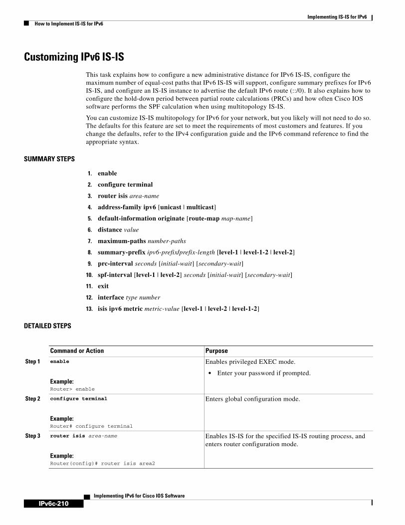
IPv6c-210
Implementing IS-IS for IPv6How to Implement IS-IS for IPv6
Implementing IPv6 for Cisco IOS Software
Customizing IPv6 IS-ISThis task explains how to configure a new administrative distance for IPv6 IS-IS, configure the maximum number of equal-cost paths that IPv6 IS-IS will support, configure summary prefixes for IPv6 IS-IS, and configure an IS-IS instance to advertise the default IPv6 route (::/0). It also explains how to configure the hold-down period between partial route calculations (PRCs) and how often Cisco IOS software performs the SPF calculation when using multitopology IS-IS.
You can customize IS-IS multitopology for IPv6 for your network, but you likely will not need to do so. The defaults for this feature are set to meet the requirements of most customers and features. If you change the defaults, refer to the IPv4 configuration guide and the IPv6 command reference to find the appropriate syntax.
SUMMARY STEPS
1. enable
2. configure terminal
3. router isis area-name
4. address-family ipv6 [unicast | multicast]
5. default-information originate [route-map map-name]
6. distance value
7. maximum-paths number-paths
8. summary-prefix ipv6-prefix/prefix-length [level-1 | level-1-2 | level-2]
9. prc-interval seconds [initial-wait] [secondary-wait]
10. spf-interval [level-1 | level-2] seconds [initial-wait] [secondary-wait]
11. exit
12. interface type number
13. isis ipv6 metric metric-value [level-1 | level-2 | level-1-2]
DETAILED STEPS
Command or Action Purpose
Step 1 enable
Example:Router> enable
Enables privileged EXEC mode.
• Enter your password if prompted.
Step 2 configure terminal
Example:Router# configure terminal
Enters global configuration mode.
Step 3 router isis area-name
Example:Router(config)# router isis area2
Enables IS-IS for the specified IS-IS routing process, and enters router configuration mode.
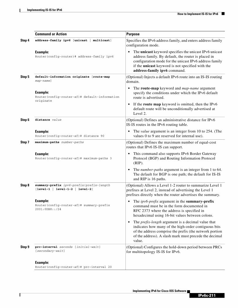
IPv6c-211
Implementing IS-IS for IPv6How to Implement IS-IS for IPv6
Implementing IPv6 for Cisco IOS Software
Step 4 address-family ipv6 [unicast | multicast]
Example:Router(config-router)# address-family ipv6
Specifies the IPv6 address family, and enters address family configuration mode.
• The unicast keyword specifies the unicast IPv6 unicast address family. By default, the router is placed in configuration mode for the unicast IPv6 address family if the unicast keyword is not specified with the address-family ipv6 command.
Step 5 default-information originate [route-map map-name]
Example:Router(config-router-af)# default-information originate
(Optional) Injects a default IPv6 route into an IS-IS routing domain.
• The route-map keyword and map-name argument specify the conditions under which the IPv6 default route is advertised.
• If the route map keyword is omitted, then the IPv6 default route will be unconditionally advertised at Level 2.
Step 6 distance value
Example:Router(config-router-af)# distance 90
(Optional) Defines an administrative distance for IPv6 IS-IS routes in the IPv6 routing table.
• The value argument is an integer from 10 to 254. (The values 0 to 9 are reserved for internal use).
Step 7 maximum-paths number-paths
Example:Router(config-router-af)# maximum-paths 3
(Optional) Defines the maximum number of equal-cost routes that IPv6 IS-IS can support.
• This command also supports IPv6 Border Gateway Protocol (BGP) and Routing Information Protocol (RIP).
• The number-paths argument is an integer from 1 to 64. The default for BGP is one path; the default for IS-IS and RIP is 16 paths.
Step 8 summary-prefix ipv6-prefix/prefix-length [level-1 | level-1-2 | level-2]
Example:Router(config-router-af)# summary-prefix 2001:0DB8::/24
(Optional) Allows a Level 1-2 router to summarize Level 1 prefixes at Level 2, instead of advertising the Level 1 prefixes directly when the router advertises the summary.
• The ipv6-prefix argument in the summary-prefix command must be in the form documented in RFC 2373 where the address is specified in hexadecimal using 16-bit values between colons.
• The prefix-length argument is a decimal value that indicates how many of the high-order contiguous bits of the address comprise the prefix (the network portion of the address). A slash mark must precede the decimal value.
Step 9 prc-interval seconds [initial-wait] [secondary-wait]
Example:Router(config-router-af)# prc-interval 20
(Optional) Configures the hold-down period between PRCs for multitopology IS-IS for IPv6.
Command or Action Purpose

IPv6c-212
Implementing IS-IS for IPv6How to Implement IS-IS for IPv6
Implementing IPv6 for Cisco IOS Software
Redistributing Routes into an IPv6 IS-IS Routing ProcessThis task explains how to redistribute IPv6 routes between protocols.
SUMMARY STEPS
1. enable
2. configure terminal
3. router isis area-name
4. address-family ipv6 [unicast | multicast]
5. redistribute protocol [process-id] [level-1 | level-1-2 | level-2] [metric metric-value] [metric-type {internal | external}] [route-map map-name]
DETAILED STEPS
Step 10 spf-interval [level-1 | level-2] seconds [initial-wait] [secondary-wait]
Example:Router(config-router-af)# spf-interval 30
(Optional) Configures how often Cisco IOS software performs the SPF calculation for multitopology IS-IS for IPv6.
Step 11 exit
Example:Router(config-router-af)# exit
Exits address family configuration mode, and returns the router to router configuration mode.
• Repeat this step to exit router configuration mode and return the router to global configuration mode.
Step 12 interface type number
Example:Router(config-router)# interface Ethernet 0/0/1
Specifies the interface type and number, and enters interface configuration mode.
Step 13 isis ipv6 metric metric-value [level-1 | level-2 | level-1-2]
Example:Router(config-if)# isis ipv6 metric 20
(Optional) Configures the value of an multitopology IS-IS for IPv6 metric.
Command or Action Purpose
Command or Action Purpose
Step 1 enable
Example:Router> enable
Enables privileged EXEC mode.
• Enter your password if prompted.
Step 2 configure terminal
Example:Router# configure terminal
Enters global configuration mode.

IPv6c-213
Implementing IS-IS for IPv6How to Implement IS-IS for IPv6
Implementing IPv6 for Cisco IOS Software
Redistributing IPv6 IS-IS Routes Between IS-IS LevelsThis task explains how to redistribute IPv6 routes learned at one IS-IS level into a different level.
SUMMARY STEPS
1. enable
2. configure terminal
3. router isis area-name
4. address-family ipv6 [unicast | multicast]
5. redistribute protocol [level-1 [into level-2] | level-1-2 | level-2 [into level-1]]
DETAILED STEPS
Step 3 router isis area-name
Example:Router(config)# router isis area2
Enables IS-IS for the specified IS-IS routing process, and enters router configuration mode.
Step 4 address-family ipv6 [unicast | multicast]
Example:Router(config-router)# address-family ipv6
Specifies the IPv6 address family, and enters address family configuration mode.
• The unicast keyword specifies the unicast IPv6 unicast address family. By default, the router is placed in configuration mode for the unicast IPv6 address family if the unicast keyword is not specified with the address-family ipv6 command.
Step 5 redistribute protocol [process-id] [level-1 | level-1-2 | level-2] [metric metric-value] [metric-type {internal | external}] [route-map map-name]
Example:Router(config-router-af)# redistribute bgp 64500 metric 100 route-map isismap
Redistributes routes from the specified protocol into the IS-IS process.
• The protocol argument can be one of the following keywords: bgp, connected, isis, rip, or static.
• Only the arguments and keywords relevant to this task are specified here.
Command or Action Purpose
Command or Action Purpose
Step 1 enable
Example:Router> enable
Enables privileged EXEC mode.
• Enter your password if prompted.
Step 2 configure terminal
Example:Router# configure terminal
Enters global configuration mode.

IPv6c-214
Implementing IS-IS for IPv6How to Implement IS-IS for IPv6
Implementing IPv6 for Cisco IOS Software
Disabling IPv6 Protocol-Support Consistency ChecksThis task explains how to disable protocol-support consistency checks in IPv6 single-topology mode.
For single-topology IS-IS IPv6, routers must be configured to run the same set of address families. IS-IS performs consistency checks on hello packets and will reject hello packets that do not have the same set of configured address families. For example, a router running IS-IS for both IPv4 and IPv6 will not form an adjacency with a router running IS-IS for IPv4 or IPv6 only. In order to allow adjacency to be formed in mismatched address-families network, the adjacency-check command in IPv6 address family configuration mode must be disabled. This command is designed for use only in special situations. Please read the following note before configuring this task.
Note Disabling the adjacency-check command can adversely affect your network configuration. Enter the no adjacency-check command only when you are running IPv4 IS-IS on all your routers and you want to add IPv6 IS-IS to your network but you need to maintain all your adjacencies during the transition. When the IPv6 IS-IS configuration is complete, remove the no adjacency-check command from the configuration.
SUMMARY STEPS
1. enable
2. configure terminal
3. router isis area-name
4. address-family ipv6 [unicast | multicast]
5. no adjacency-check
Step 3 router isis area-name
Example:Router(config)# router isis area2
Enables IS-IS for the specified IS-IS routing process, and enters router configuration mode.
Step 4 address-family ipv6 [unicast | multicast]
Example:Router(config-router)# address-family ipv6
Specifies the IPv6 address family, and enters address family configuration mode.
• The unicast keyword specifies the unicast IPv6 unicast address family. By default, the router is placed in configuration mode for the unicast IPv6 address family if the unicast keyword is not specified with the address-family ipv6 command.
Step 5 redistribute protocol [level-1 [into level-2] | level-1-2 | level-2 [into level-1]]
Example:Router(config-router-af)# redistribute isis level-1 into level-2
Redistributes IPv6 routes from one IS-IS level into another IS-IS level.
• By default, the routes learned by Level 1 instances are redistributed by the Level 2 instance.
Note The protocol argument must be isis in this configuration of the redistribute command. Only the arguments and keywords relevant to this task are specified here.
Command or Action Purpose

IPv6c-215
Implementing IS-IS for IPv6How to Implement IS-IS for IPv6
Implementing IPv6 for Cisco IOS Software
DETAILED STEPS
Disabling IPv4 Subnet Consistency ChecksThis task explains how to disable IPv4 subnet consistency checking when forming adjacencies. Cisco IOS software historically makes checks on hello packets to ensure that the IPv4 address is present and has a consistent subnet with the neighbor from which the hello packets are received. To disable this check, use the no adjacency-check command in the router configuration mode. However, if multitopology IS-IS is configured, this check is automatically suppressed, because multitopology IS-IS requires routers to form an adjacency regardless of whether or not all routers on a LAN support a common protocol.
SUMMARY STEPS
1. enable
2. configure terminal
3. router isis area-name
4. no adjacency-check
Command or Action Purpose
Step 1 enable
Example:Router> enable
Enables privileged EXEC mode.
• Enter your password if prompted.
Step 2 configure terminal
Example:Router# configure terminal
Enters global configuration mode.
Step 3 router isis area-name
Example:Router(config)# router isis area2
Enables IS-IS for the specified IS-IS routing process, and enters router configuration mode.
Step 4 address-family ipv6 [unicast | multicast]
Example:Router(config-router)# address-family ipv6
Specifies the IPv6 address family, and enters address family configuration mode.
• The unicast keyword specifies the unicast IPv6 unicast address family. By default, the router is placed in configuration mode for the unicast IPv6 address family if the unicast keyword is not specified with the address-family ipv6 command.
Step 5 no adjacency-check
Example:Router(config-router-af)# no adjacency-check
Disables the IPv6 protocol-support consistency checks performed on hello packets, allowing IPv6 to be introduced into an IPv4-only network without disrupting existing adjacencies.
• The adjacency-check command is enabled by default.
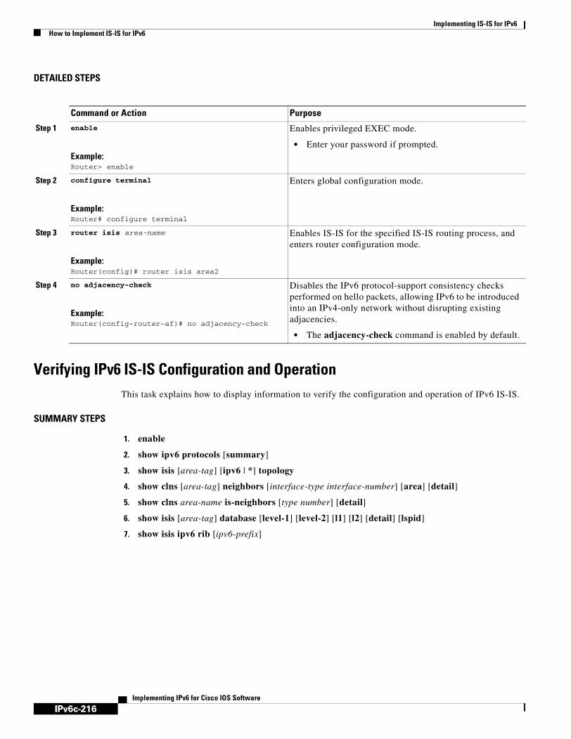
IPv6c-216
Implementing IS-IS for IPv6How to Implement IS-IS for IPv6
Implementing IPv6 for Cisco IOS Software
DETAILED STEPS
Verifying IPv6 IS-IS Configuration and OperationThis task explains how to display information to verify the configuration and operation of IPv6 IS-IS.
SUMMARY STEPS
1. enable
2. show ipv6 protocols [summary]
3. show isis [area-tag] [ipv6 | *] topology
4. show clns [area-tag] neighbors [interface-type interface-number] [area] [detail]
5. show clns area-name is-neighbors [type number] [detail]
6. show isis [area-tag] database [level-1] [level-2] [l1] [l2] [detail] [lspid]
7. show isis ipv6 rib [ipv6-prefix]
Command or Action Purpose
Step 1 enable
Example:Router> enable
Enables privileged EXEC mode.
• Enter your password if prompted.
Step 2 configure terminal
Example:Router# configure terminal
Enters global configuration mode.
Step 3 router isis area-name
Example:Router(config)# router isis area2
Enables IS-IS for the specified IS-IS routing process, and enters router configuration mode.
Step 4 no adjacency-check
Example:Router(config-router-af)# no adjacency-check
Disables the IPv6 protocol-support consistency checks performed on hello packets, allowing IPv6 to be introduced into an IPv4-only network without disrupting existing adjacencies.
• The adjacency-check command is enabled by default.

IPv6c-217
Implementing IS-IS for IPv6How to Implement IS-IS for IPv6
Implementing IPv6 for Cisco IOS Software
DETAILED STEPS
Troubleshooting Tips
You can use several system debugging commands to check your IS-IS for IPv6 implementation.
If adjacencies are not coming up properly, use the debug isis adj-packets command.
If you are using IS-IS multitopology for IPv6 and want to display statistical information about building routes between intermediate systems, use the debug isis spf-statistics command.
To display a log of significant events during an IS-IS SPF computation, use the debug isis spf-events command.
Command or Action Purpose
Step 1 enable
Example:Router> enable
Enables privileged EXEC mode.
• Enter your password if prompted.
Step 2 show ipv6 protocols [summary]
Example:Router# show ipv6 protocols
Displays the parameters and current state of the active IPv6 routing processes.
Step 3 show isis [area-tag] [ipv6 | *] topology
Example:Router# show isis topology
Displays a list of all connected routers running IS-IS in all areas.
Step 4 show clns [area-tag] neighbors [interface-type interface-number] [area] [detail]
Example:Router# show clns neighbors detail
Displays end system (ES), intermediate system (IS), and multitopology IS-IS (M-ISIS) neighbors.
Step 5 show clns area-name is-neighbors [type number] [detail]
Example:Router# show clns is-neighbors detail
Displays IS-IS adjacency information for IS-IS neighbors.
• Use the detail keyword to display the IPv6 link-local addresses of the neighbors.
Step 6 show isis [area-tag] database [level-1] [level-2] [l1] [l2] [detail] [lspid]
Example:Router# show isis database detail
Displays the IS-IS link-state database.
• In this example, the contents of each LSP are displayed using the detail keyword.
Step 7 show isis ipv6 rib [ipv6-prefix]
Example:Router# show isis ipv6 rib
Displays the IPv6 local RIB.

IPv6c-218
Implementing IS-IS for IPv6How to Implement IS-IS for IPv6
Implementing IPv6 for Cisco IOS Software
Examples
This section provides the following output examples:
• Sample Output for the show ipv6 protocols Command
• Sample Output for the show isis topology Command
• Sample Output for the show clns is-neighbors Command
• Sample Output for the show isis database Command
• Sample Output for the show isis ipv6 rib Command
Sample Output for the show ipv6 protocols Command
In the following example, output information about the parameters and current state of that active IPv6 routing processes is displayed using the show ipv6 protocols EXEC command:
Router# show ipv6 protocols
IPv6 Routing Protocol is "connected"IPv6 Routing Protocol is "static"IPv6 Routing Protocol is "isis" Interfaces: Ethernet0/0/3 Ethernet0/0/1 Serial1/0/1 Loopback1 (Passive) Loopback2 (Passive) Loopback3 (Passive) Loopback4 (Passive) Loopback5 (Passive) Redistribution: Redistributing protocol static at level 1 Address Summarization: L2: 2001:0DB8:33::/16 advertised with metric 0 L2: 2001:0DB8:44::/16 advertised with metric 20 L2: 2001:0DB8:66::/16 advertised with metric 10 L2: 2001:0DB8:77::/16 advertised with metric 10
Sample Output for the show isis topology Command
In the following example, output information about all connected routers running IS-IS in all areas is displayed using the show isis topology EXEC command:
Router# show isis topology
IS-IS paths to level-1 routersSystem Id Metric Next-Hop Interface SNPA0000.0000.000C 0000.0000.000D 20 0000.0000.00AA Se1/0/1 *HDLC*0000.0000.000F 10 0000.0000.000F Et0/0/1 0050.e2e5.d01d0000.0000.00AA 10 0000.0000.00AA Se1/0/1 *HDLC*
IS-IS paths to level-2 routersSystem Id Metric Next-Hop Interface SNPA0000.0000.000A 10 0000.0000.000A Et0/0/3 0010.f68d.f0630000.0000.000B 20 0000.0000.000A Et0/0/3 0010.f68d.f0630000.0000.000C --0000.0000.000D 30 0000.0000.000A Et0/0/3 0010.f68d.f0630000.0000.000E 30 0000.0000.000A Et0/0/3 0010.f68d.f063

IPv6c-219
Implementing IS-IS for IPv6How to Implement IS-IS for IPv6
Implementing IPv6 for Cisco IOS Software
Sample Output for the show clns neighbors Command
In the following example, detailed output information that displays both end system (ES) and intermediate system (IS) neighbors is displayed using the show clns neighbors command with the detail keyword.
Router# show clns neighbors detail
System Id Interface SNPA State Holdtime Type Protocol0000.0000.0007 Et3/3 aa00.0400.6408 UP 26 L1 IS-ISArea Address(es): 20IP Address(es): 172.16.0.42*Uptime: 00:21:490000.0C00.0C35 Et3/2 0000.0c00.0c36 Up 91 L1 IS-ISArea Address(es): 20IP Address(es): 192.168.0.42*Uptime: 00:21:520800.2B16.24EA Et3/3 aa00.0400.2d05 Up 27 L1 M-ISISArea Address(es): 20IP Address(es): 192.168.0.42*IPv6 Address(es): FE80::2B0:8EFF:FE31:EC57Uptime: 00:00:270800.2B14.060E Et3/2 aa00.0400.9205 Up 8 L1 IS-ISArea Address(es): 20IP Address(es): 192.168.0.30*Uptime: 00:21:52
Sample Output for the show clns is-neighbors Command
In the following example, output information to confirm that the local router has formed all the necessary IS-IS adjacencies with other IS-IS neighbors is displayed using the show clns is-neighbors EXEC command. To display the IPv6 link-local addresses of the neighbors, specify the detail keyword.
Router# show clns is-neighbors detail
System Id Interface State Type Priority Circuit Id Format0000.0000.00AA Se1/0/1 Up L1 0 00 Phase V Area Address(es): 49.0001 IPv6 Address(es): FE80::YYYY:D37C:C854:5 Uptime: 17:21:380000.0000.000F Et0/0/1 Up L1 64 0000.0000.000C.02 Phase V Area Address(es): 49.0001 IPv6 Address(es): FE80::XXXX:E2FF:FEE5:D01D Uptime: 17:21:410000.0000.000A Et0/0/3 Up L2 64 0000.0000.000C.01 Phase V Area Address(es): 49.000b IPv6 Address(es): FE80::ZZZZ:F6FF:FE8D:F063 Uptime: 17:22:06
Sample Output for the show isis database Command
In the following example, detailed output information about LSPs received from other routers and the IPv6 prefixes they are advertising is displayed using the show isis database EXEC command with the detail keyword specified:
Router# show isis database detail
IS-IS Level-1 Link State DatabaseLSPID LSP Seq Num LSP Checksum LSP Holdtime ATT/P/OL0000.0C00.0C35.00-00 0x0000000C 0x5696 325 0/0/0

IPv6c-220
Implementing IS-IS for IPv6How to Implement IS-IS for IPv6
Implementing IPv6 for Cisco IOS Software
Area Address: 47.0004.004D.0001Area Address: 39.0001Metric: 10 IS 0000.0C00.62E6.03Metric: 0 ES 0000.0C00.0C35
--More--0000.0C00.40AF.00-00* 0x00000009 0x8452 608 1/0/0
Area Address: 47.0004.004D.0001Topology: IPv4 (0x0) IPv6 (0x2)NLPID: 0xCC 0x8EIP Address: 172.16.21.49Metric: 10 IS 0800.2B16.24EA.01Metric: 10 IS 0000.0C00.62E6.03Metric: 0 ES 0000.0C00.40AFIPv6 Address: 2001:0DB8::/32Metric: 10 IPv6 (MT-IPv6) 2001:0DB8::/64Metric: 5 IS-Extended cisco.03Metric: 10 IS-Extended cisco1.03Metric: 10 IS (MT-IPv6) cisco.03
IS-IS Level-2 Link State Database:LSPID LSP Seq Num LSP Checksum LSP Holdtime ATT/P/OL0000.0000.000A.00-00 0x00000059 0x378A 949 0/0/0 Area Address: 49.000b NLPID: 0x8E IPv6 Address: 2001:0DB8:1:1:1:1:1:1 Metric: 10 IPv6 2001:0DB8:2:YYYY::/64 Metric: 10 IPv6 2001:0DB8:3:YYYY::/64 Metric: 10 IPv6 2001:0DB8:2:YYYY::/64 Metric: 10 IS-Extended 0000.0000.000A.01 Metric: 10 IS-Extended 0000.0000.000B.00 Metric: 10 IS-Extended 0000.0000.000C.01 Metric: 0 IPv6 11:1:YYYY:1:1:1:1:1/128 Metric: 0 IPv6 11:2:YYYY:1:1:1:1:1/128 Metric: 0 IPv6 11:3:YYYY:1:1:1:1:1/128 Metric: 0 IPv6 11:4:YYYY:1:1:1:1:1/128 Metric: 0 IPv6 11:5:YYYY:1:1:1:1:1/1280000.0000.000A.01-00 0x00000050 0xB0AF 491 0/0/0 Metric: 0 IS-Extended 0000.0000.000A.00 Metric: 0 IS-Extended 0000.0000.000B.00
Sample Output for the show isis ipv6 rib Command
The following example shows output from the show isis ipv6 rib command. An asterisk (*) indicates prefixes that have been installed in the master IPv6 RIB as IS-IS routes. Following each prefix is a list of all paths in order of preference, with optimal paths listed first and suboptimal paths listed after optimal paths.
Router# show isis ipv6 rib
IS-IS IPv6 process "", local RIB2001:0DB8:88:1::/64
via FE80::210:7BFF:FEC2:ACC9/Ethernet2/0, type L2 metric 20 LSP [3/7] via FE80::210:7BFF:FEC2:ACCC/Ethernet2/1, type L2 metric 20 LSP [3/7]* 2001:0DB8:1357:1::/64 via FE80::202:7DFF:FE1A:9471/Ethernet2/1, type L2 metric 10 LSP [4/9]* 2001:0DB8:45A::/64 via FE80::210:7BFF:FEC2:ACC9/Ethernet2/0, type L1 metric 20 LSP [C/6] via FE80::210:7BFF:FEC2:ACCC/Ethernet2/1, type L1 metric 20 LSP [C/6] via FE80::210:7BFF:FEC2:ACC9/Ethernet2/0, type L2 metric 20 LSP [3/7] via FE80::210:7BFF:FEC2:ACCC/Ethernet2/1, type L2 metric 20 LSP [3/7]

IPv6c-221
Implementing IS-IS for IPv6Configuration Examples for IPv6 IS-IS
Implementing IPv6 for Cisco IOS Software
Configuration Examples for IPv6 IS-ISThis section provides the following configuration examples:
• Configuring Single-Topology IS-IS for IPv6 Example, page 221
• Customizing IPv6 IS-IS Example, page 221
• Redistributing Routes into an IPv6 IS-IS Routing Process Example, page 221
• Redistributing IPv6 IS-IS Routes Between IS-IS Levels Example, page 222
• Disabling IPv6 Protocol-Support Consistency Checks Example, page 222
• Configuring Multitopology IS-IS for IPv6 Example, page 222
• Configuring the IS-IS IPv6 Metric for Multitopology IS-IS Example, page 222
Configuring Single-Topology IS-IS for IPv6 ExampleThe following example enables single-topology mode, creates an IS-IS process, defines the NET, configures an IPv6 address on an interface, and configures the interface to run IPv6 IS-IS:
ipv6 unicast-routing!router isisnet 49.0001.0000.0000.000c.00exit
interface Ethernet0/0/1ipv6 address 2001:0DB8::3/64ipv6 router isis area2
Customizing IPv6 IS-IS ExampleThe following example advertises the IPv6 default route (::/0)—with an origin of Ethernet interface 0/0/1—with all other routes in router updates sent on Ethernet interface 0/0/1. This example also sets an administrative distance for IPv6 IS-IS to 90, defines the maximum number of equal-cost paths that IPv6 IS-IS will support as 3, and configures a summary prefix of 2001:0DB8::/24 for IPv6 IS-IS.
router isis address-family ipv6default-information originatedistance 90maximum-paths 3summary-prefix 2001:0DB8::/24exit
Redistributing Routes into an IPv6 IS-IS Routing Process ExampleThe following example redistributes IPv6 BGP routes into the IPv6 IS-IS Level 2 routing process:
router isis address-family ipv6redistribute bgp 64500 metric 100 route-map isismapexit

IPv6c-222
Implementing IS-IS for IPv6Where to Go Next
Implementing IPv6 for Cisco IOS Software
Redistributing IPv6 IS-IS Routes Between IS-IS Levels ExampleThe following example redistributes IPv6 IS-IS Level 1 routes into the IPv6 IS-IS Level 2 routing process:
router isisaddress-family ipv6redistribute isis level-1 into level-2exit
Disabling IPv6 Protocol-Support Consistency Checks ExampleThe following example disables the adjacency-check command to allow a network administrator to configure IPv6 IS-IS on the router without disrupting the existing adjacencies:
router isis address-family ipv6no adjacency-checkexit
Configuring Multitopology IS-IS for IPv6 ExampleThe following example configures multitopology IS-IS in IPv6 after you have configured IS-IS for IPv6:
router isismetric-style wideaddress-family ipv6multi-topology
exit
Configuring the IS-IS IPv6 Metric for Multitopology IS-IS ExampleThe following example sets the value of an IS-IS IPv6 metric to 20:
interface Ethernet 0/0/1isis ipv6 metric 20
Where to Go NextIf you want to implement more IPv6 routing protocols, refer to the Implementing RIP for IPv6 or Implementing Multiprotocol BGP for IPv6 module.

IPv6c-223
Implementing IS-IS for IPv6Additional References
Implementing IPv6 for Cisco IOS Software
Additional ReferencesFor additional information related to Implementing IS-IS for IPv6, see the following sections:
• Related Documents, page 224
• Standards, page 224
• MIBs, page 224
• RFCs, page 224
• Technical Assistance, page 224

IPv6c-224
Implementing IS-IS for IPv6Additional References
Implementing IPv6 for Cisco IOS Software
Related Documents
Standards
MIBs
RFCs
Technical Assistance
Related Topic Document Title
IS-IS configuration tasks “Configuring Integrated IS-IS” chapter in the Cisco IOS IP Configuration Guide, Release 12.4
IS-IS commands: complete command syntax, command mode, defaults, usage guidelines, and examples
Cisco IOS IP Command Reference, Volume 2 of 3: Routing Protocols, Release 12.4
IPv6 supported feature list Start Here: Cisco IOS Software Release Specifics for IPv6 Features
IPv6 commands: complete command syntax, command mode, defaults, usage guidelines, and examples
IPv6 for Cisco IOS Command Reference
IPv4 configuration and command reference information
Cisco IOS Release 12.4 Configuration Guides and Command References
Standards Title
Draft-ietf-isis-ipv6.txt Routing IPv6 with IS-IS, October 31, 2002
Draft-ietf-isis-wg-multi-topology.txt M-ISIS: Multi-Topology (MT) Routing in IS-IS, October 2, 2002
MIBs MIBs Link
• CISCO-IETF-IP-FORWARD-MIB
• CISCO-IETF-IP-MIB
To locate and download MIBs for selected platforms, Cisco IOS releases, and feature sets, use Cisco MIB Locator found at the following URL:
http://www.cisco.com/go/mibs
RFCs Title
RFC 1195 Use of OSI IS-IS for Routing in TCP/IP and Dual Environments
Description Link
The Cisco Technical Support website contains thousands of pages of searchable technical content, including links to products, technologies, solutions, technical tips, and tools. Registered Cisco.com users can log in from this page to access even more content.
http://www.cisco.com/techsupport

IPv6c-225Implementing IPv6 for Cisco IOS Software
Implementing IPv6 over MPLS
Multiprotocol Label Switching (MPLS) is deployed by many service providers in their IPv4 networks. Service providers want to introduce IPv6 services to their customers, but changes to their existing IPv4 infrastructure can be expensive and the cost benefit for a small amount of IPv6 traffic does not make economic sense. Several integration scenarios have been developed to leverage an existing IPv4 MPLS infrastructure and add IPv6 services without requiring any changes to the network backbone.
Finding Support Information for Platforms and Cisco IOS Software Images
Use Cisco Feature Navigator to find information about platform support and Cisco IOS software image support. Access Cisco Feature Navigator at http://www.cisco.com/go/fn. You must have an account on Cisco.com. If you do not have an account or have forgotten your username or password, click Cancel at the login dialog box and follow the instructions that appear.
Contents• Prerequisites for Implementing IPv6 over MPLS, page 225
• Information About Implementing IPv6 over MPLS, page 226
• How to Implement IPv6 over MPLS, page 230
• Configuration Examples for IPv6 over MPLS, page 239
• Where to Go Next, page 241
• Additional References, page 241
Prerequisites for Implementing IPv6 over MPLS• This module assumes that you are familiar with IPv4. Refer to the publications referenced in the
“Related Documents” section for IPv4 configuration and command reference information.
• Before the IPv6 Provider Edge Router over MPLS (6PE) feature can be implemented, MPLS must be running over the core IPv4 network. If Cisco routers are used, Cisco Express Forwarding (CEF) or distributed CEF (dCEF) must be enabled for both IPv4 and IPv6 protocols. This module assumes that you are familiar with MPLS.
Table 10 identifies the earliest release for each early-deployment train in which the feature became available.

IPv6c-226
Implementing IPv6 over MPLSInformation About Implementing IPv6 over MPLS
Implementing IPv6 for Cisco IOS Software
Information About Implementing IPv6 over MPLSTo configure IPv6 over MPLS, you need to understand the following concepts:
• Benefits of Deploying IPv6 over MPLS Backbones, page 226
• IPv6 over a Circuit Transport over MPLS, page 226
• IPv6 Using Tunnels on the Customer Edge Routers, page 227
• IPv6 on the Provider Edge Routers (6PE), page 228
Benefits of Deploying IPv6 over MPLS BackbonesIPv6 over MPLS backbones enables isolated IPv6 domains to communicate with each other over an MPLS IPv4 core network. This implementation requires only a few backbone infrastructure upgrades and no reconfiguration of core routers because forwarding is based on labels rather than the IP header itself, providing a very cost-effective strategy for the deployment of IPv6.
Additionally, the inherent Virtual Private Network (VPN) and MPLS traffic engineering (MPLS-TE) services available within an MPLS environment allow IPv6 networks to be combined into IPv4 VPNs or extranets over an infrastructure supporting IPv4 VPNs and MPLS-TE. IPv6 VPNs are not supported.
IPv6 over a Circuit Transport over MPLSUsing any circuit transport for deploying IPv6 over MPLS networks has no impact on the operation or infrastructure of MPLS, and requires no configuration changes to the core or provider edge routers. Communication between the remote IPv6 domains runs native IPv6 protocols over a dedicated link, where the underlying mechanisms are fully transparent to IPv6. The IPv6 traffic is tunneled using the Any Transport over MPLS (MPLS/AToM) or Ethernet over MPLS (EoMPLS) feature with the routers connected through an ATM OC-3 or Ethernet interface, respectively.
Figure 22 shows the configuration for IPv6 over any circuit transport over MPLS.
Table 10 Minimum Required Cisco IOS Release
FeatureMinimum Required Cisco IOS Release by Release Train
IPv6 over a circuit transport over IPv6 12.2(15)T, 12.0(22)S, 12.2(14)S, 12.3, 12.3(2)T, 12.4, 12.4(2)T, 12.2(28)SB
IPv6 using tunnels over the customer edge routers 12.2(15)T, 12.0(22)S, 12.2(14)S, 12.3, 12.3(2)T, 12.4, 12.4(2)T, 12.2(28)SB
IPv6 on the provider edge routers (6PE) 12.2(15)T, 12.0(22)S, 12.2(14)S, 12.3, 12.3(2)T, 12.4, 12.4(2)T, 12.2(28)SB
6PE multipath 12.2(25)S, 12.4(6)T, 12.2(28)SB
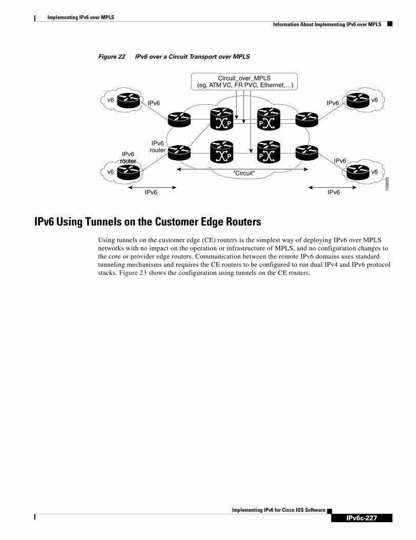
IPv6c-227
Implementing IPv6 over MPLSInformation About Implementing IPv6 over MPLS
Implementing IPv6 for Cisco IOS Software
Figure 22 IPv6 over a Circuit Transport over MPLS
IPv6 Using Tunnels on the Customer Edge RoutersUsing tunnels on the customer edge (CE) routers is the simplest way of deploying IPv6 over MPLS networks with no impact on the operation or infrastructure of MPLS, and no configuration changes to the core or provider edge routers. Communication between the remote IPv6 domains uses standard tunneling mechanisms and requires the CE routers to be configured to run dual IPv4 and IPv6 protocol stacks. Figure 23 shows the configuration using tunnels on the CE routers.
1036
29
IPv6router
Circuit_over_MPLS (eg. ATM VC, FR PVC, Ethernet,…)
IPv6 IPv6
IPv6
IPv6IPv6v6
v6
v6
v6"Circuit"
P P
P P
IPv6IPv6routerIPv6
router

IPv6c-228
Implementing IPv6 over MPLSInformation About Implementing IPv6 over MPLS
Implementing IPv6 for Cisco IOS Software
Figure 23 IPv6 Using Tunnels on the CE Routers
Refer to the Implementing Tunnels for IPv6 module for configuration information on manually configured tunnels, automatic tunnels, and 6to4 tunnels.
Limitations on using tunnels involve the manual configuring of a mesh of tunnels on the CE routers, creating scaling issues for large networks.
IPv6 on the Provider Edge Routers (6PE)The Cisco implementation of IPv6 provider edge router over MPLS is referred to as Cisco 6PE and enables IPv6 sites to communicate with each other over an MPLS IPv4 core network using MPLS label switched paths (LSPs). This feature relies on multiprotocol Border Gateway Protocol (BGP) extensions in the IPv4 network configuration on the provider edge (PE) router to exchange IPv6 reachability information in addition to an MPLS label for each IPv6 address prefix to be advertised. Edge routers are configured to be dual stack running both IPv4 and IPv6, and use the IPv4 mapped IPv6 address for IPv6 prefix reachability exchange.
A hierarchy of labels is imposed on the 6PE ingress router to keep the IPv6 traffic transparent to all the core routers. The top label provides connectivity inside the IPv4 MPLS core network and the label is distributed by Label Distribution Protocol (LDP), Tag Distribution Protocol (TDP), or Resource Reservation Protocol (RSVP). TDP and LDP can both be used for label distribution, but RSVP is used only in the context of MPLS-TE label exchange. The bottom label, automatically assigned to the IPv6 prefix of the destination, is distributed by multiprotocol BGP and used at each 6PE egress router for IPv6 forwarding.
In Figure 24 the 6PE routers are configured as dual stack routers able to route both IPv4 and IPv6 traffic. Each 6PE router is configured to run LDP, TDP, or RSVP (if traffic engineering is configured) to bind the IPv4 labels. The 6PE routers use multiprotocol BGP to exchange reachability information with the other 6PE devices within the MPLS domain, and to distribute aggregate IPv6 labels between them. All
v6
IPv6 IPv6
IPv6 over IPv4 tunnels
7271
9
v6
v4
IPv4 IPv6
Dual stackIPv4-IPv6CE routers
Dual stackIPv4-IPv6CE routers
v6
v6
IPv6 IPv4
v4
v4
IPv4
OC-48/192
PEP
P PE
PE
P
PPE

IPv6c-229
Implementing IPv6 over MPLSInformation About Implementing IPv6 over MPLS
Implementing IPv6 for Cisco IOS Software
6PE and core routers—P routers in Figure 3—within the MPLS domain share a common IPv4 Interior Gateway Protocol (IGP) such as Open Shortest Path First (OSPF) or Integrated Intermediate System-to-Intermediate System (IS-IS).
Figure 24 6PE Router Topology
The interfaces on the 6PE routers connecting to the CE router can be configured to forward IPv6 traffic, IPv4 traffic, or both types of traffic depending on the customer requirements. 6PE routers advertise IPv6 reachability information learned from their 6PE peers over the MPLS cloud. Service providers can delegate an IPv6 prefix from their registered IPv6 prefixes over the 6PE infrastructure; otherwise, there is no impact on the CE router.
The P routers in the core of the network are not aware that they are switching IPv6 packets. Core routers are configured to support MPLS and the same IPv4 IGP as the PE routers to establish internal reachability inside the MPLS cloud. Core routers also use LDP, TDP, or RSVP for binding IPv4 labels. Implementing the Cisco 6PE feature does not have any impact on the MPLS core devices.
Within the MPLS network, IPv6 traffic is forwarded using label switching, making the IPv6 traffic transparent to the core of the MPLS network. No IPv6 over IPv4 tunnels or Layer 2 encapsulation methods are required.
6PE Multipath
Internal and external Border Gateway Protocol (BGP) multipath for IPv6 allows the IPv6 router to load balance between several paths (for example, same neighboring autonomous system [AS] or sub-AS, or the same metric) to reach its destination. The 6PE multipath feature uses multiprotocol internal BGP (MP-iBGP) to distribute IPv6 routes over the MPLS IPv4 core network and to attach an MPLS label to each route.
When MP-iBGP multipath is enabled on the 6PE router, all labeled paths are installed in the forwarding table with MPLS information (label stack) when MPLS information is available. This functionality enables 6PE to perform load balancing.
v6
IPv6 IPv6
MP-iBGP sessions
6514
1
v6
v4
IPv4 IPv6
v6
v6
IPv6 IPv4
v4
v4
IPv4
6PE
P P
6PE
6PE
PP
6PE

IPv6c-230
Implementing IPv6 over MPLSHow to Implement IPv6 over MPLS
Implementing IPv6 for Cisco IOS Software
How to Implement IPv6 over MPLSThe following sections explain how to configure IPv6 over MPLS:
• Deploying IPv6 over a Circuit Transport over MPLS, page 230
• Deploying IPv6 on the Provider Edge Routers (6PE), page 230
• Configuring iBGP Multipath Load Sharing, page 234
• Verifying 6PE Configuration and Operation, page 235
Deploying IPv6 over a Circuit Transport over MPLSTo deploy IPv6 over a circuit transport over MPLS, the IPv6 routers must be configured for IPv6 connectivity. Refer to the Implementing Basic Connectivity for IPv6 module for details on basic IPv6 configuration. The MPLS router configuration requires AToM configuration or EoMPLS configuration. Refer to the AToM new feature module in Cisco IOS Release 12.0(23)S for details on configuration and command reference information.
Deploying IPv6 on the Provider Edge Routers (6PE)To implement IPv6 on provider edge routers two tasks must be completed. The first task is to specify the interface from which locally generated packets take their source IPv6 address. The second task is to bind and advertise aggregate labels.
Each 6PE router—6PE1 and 6PE2 in Figure 25—is assumed to be running IPv4 routing and CEF.
6PE Network Configuration
Two configuration tasks using the network shown in Figure 25 are required at the 6PE1 router to enable the 6PE feature.
The customer edge router—CE1 in Figure 25—is configured to forward its IPv6 traffic to the 6PE1 router. The P1 router in the core of the network is assumed to be running MPLS, a label distribution protocol, an IPv4 IGP, and CEF or dCEF, and does not require any new configuration to enable the 6PE feature. Although new configuration tasks are not required for the CE1 and P1 routers, configuration examples are shown for reference in the “6PE Configuration Example” section.
Figure 25 6PE Configuration Example
CE1
CE2
IPv6 Prefix: 3ffe:b00:ffff::/48
IPv6 Prefix: 3ffe:b00:dddd::/48
AS65000
P1
BGP + IS-IS
S 0/0 E 0/06PE2
E 0/0192.168.99.1
L0 192.168.99.5 L0 192.168.99.70
6PE1
7244
3

IPv6c-231
Implementing IPv6 over MPLSHow to Implement IPv6 over MPLS
Implementing IPv6 for Cisco IOS Software
Prerequisites
• The 6PE routers—the 6PE1 and 6PE2 routers in Figure 25—must be members of the core IPv4 network. The 6PE router interfaces attached to the core network must be running MPLS, the same label distribution protocol, and the same IPv4 IGP, as in the core network.
• The 6PE routers must also be configured to be dual stack to run both IPv4 and IPv6.
Restrictions
Note As of Cisco IOS Release 12.2(22)S, the following restrictions do not apply to Cisco IOS 12.2 S releases.
The following restrictions apply when implementing the IPv6 Provider Edge Router over MPLS (6PE) feature:
• Core MPLS routers are supporting MPLS and IPv4 only, so they cannot forward or create any IPv6 Internet Control Message Protocol (ICMP) messages.
• Load balancing ability is not provided by Cisco 6PE between an MPLS path and an IPv6 path. If both are available, the MPLS path is always preferred. Load balancing between two MPLS paths is possible.
• BGP multipath is not supported for Cisco 6PE routes. If two BGP peers advertise the same prefix with an equal cost, Cisco 6PE will use the last route to cross the MPLS core.
• 6PE feature is not supported over tunnels other than RSVP-TE tunnels.
Specifying the Source Address Interface on a 6PE Router
This task explains how to specify the interface from which locally generated packets take their source IPv6 address. This task is the first of two tasks that must be completed to deploy 6PE. See the “Binding and Advertising the 6PE Label to Advertise Prefixes” task for details about the second task required to implement 6PE.
SUMMARY STEPS
1. enable
2. configure terminal
3. ipv6 unicast-routing
4. ipv6 cef
5. interface type number
6. ipv6 address ipv6-prefix/prefix-length [eui-64]
7. exit
8. mpls ipv6 source-interface type number

IPv6c-232
Implementing IPv6 over MPLSHow to Implement IPv6 over MPLS
Implementing IPv6 for Cisco IOS Software
DETAILED STEPS
Command or Action Purpose
Step 1 enable
Example:Router> enable
Enables privileged EXEC mode.
• Enter your password if prompted.
Step 2 configure terminal
Example:Router# configure terminal
Enters global configuration mode.
Step 3 ipv6 unicast-routing
Example:Router(config)# ipv6 unicast-routing
Enables the forwarding of IPv6 unicast datagrams.
Step 4 ipv6 cef
Example:Router(config)# ipv6 cef
Enables IPv6 CEF.
Step 5 interface type number
Example:Router(config)# interface Serial 0/0
Specifies an interface type and number and enters interface configuration mode.
• In the context of this feature, the interface to be configured is the interface communicating with the CE router.
Step 6 ipv6 address ipv6-prefix/prefix-length [eui-64]
Example:Router(config-if)# ipv6 address 2001:0DB8:FFFF::2/64
Specifies an IPv6 network assigned to the interface and enables IPv6 processing on the interface.
• Specifying the ipv6 address ipv6-prefix/prefix-length interface configuration command without the eui-64 keyword configures site-local and global IPv6 addresses.
• Specifying the ipv6 address ipv6-prefix/prefix-length command with the eui-64 keyword configures site-local and global IPv6 addresses with an interface identifier (ID) in the low-order 64 bits of the IPv6 address. Only the 64-bit network prefix for the address needs to be specified; the last 64 bits are automatically computed from the interface ID.
• The link-local address for an interface is automatically configured when IPv6 is enabled on the interface.

IPv6c-233
Implementing IPv6 over MPLSHow to Implement IPv6 over MPLS
Implementing IPv6 for Cisco IOS Software
Binding and Advertising the 6PE Label to Advertise Prefixes
This task is the second task required for implementing 6PE. The “Specifying the Source Address Interface on a 6PE Router” task must be completed first. This task explains how to enable the binding and advertising of aggregate labels when advertising IPv6 prefixes to a specified BGP neighbor.
SUMMARY STEPS
1. enable
2. configure terminal
3. router bgp autonomous-system-number
4. no bgp default ipv4-unicast
5. neighbor {ip-address | peer-group-name} remote-as autonomous-system-number
6. neighbor {ip-address | peer-group-name} update-source interface-type interface-number
7. address-family ipv6 [unicast]
8. neighbor {ip-address | peer-group-name} activate
9. neighbor ip-address send-label
DETAILED STEPS
Step 7 exit
Example:Router(config-if)# exit
Exits interface configuration mode and enters global configuration mode.
Step 8 mpls ipv6 source-interface type number
Example:Router(config)# mpls ipv6 source-interface Loopback 0
Specifies the interface type and number from which MPLS will take the IPv6 address as a source address.
Note Effective with release 12.2(25)S, the mpls ipv6 source-interface command is no longer available in Cisco IOS software.
Command or Action Purpose
Command or Action Purpose
Step 1 enable
Example:Router> enable
Enables privileged EXEC mode.
• Enter your password if prompted.
Step 2 configure terminal
Example:Router# configure terminal
Enters global configuration mode.
Step 3 router bgp autonomous-system-number
Example:Router(config)# router bgp 65000
Enters router configuration mode for the specified routing process.

IPv6c-234
Implementing IPv6 over MPLSHow to Implement IPv6 over MPLS
Implementing IPv6 for Cisco IOS Software
Configuring iBGP Multipath Load Sharing
This task describes how to configure iBGP multipath load sharing and control the maximum number of parallel iBGP routes that can be installed in a routing table.
Step 4 no bgp default ipv4-unicast
Example:Router(config-router)# no bgp default ipv4-unicast
Disables the IPv4 unicast address family for the BGP routing process specified in the previous step.
Note Routing information for the IPv4 unicast address family is advertised by default for each BGP routing session configured with the neighbor remote-as router configuration command unless you configure the no bgp default ipv4-unicast router configuration command before configuring the neighbor remote-as command.
Step 5 neighbor {ip-address | peer-group-name} remote-as autonomous-system-number
Example:Router(config-router)# neighbor 192.168.99.70 remote-as 65000
Adds the IP address of the neighbor in the specified autonomous system to the BGP neighbor table of the local router.
Step 6 neighbor {ip-address | peer-group-name} update-source interface-type interface-number
Example:Router(config-router)# neighbor 192.168.99.70 update-source Loopback 0
Specifies the interface whose IPv4 address is to be used as the source address for the peering.
• In the context of this task, the interface must have an IPv4 address with a 32-bit mask configured. Use of a loopback interface is recommended. This address is used to determine the IPv6 next hop by the peer 6PE.
Step 7 address-family ipv6 [unicast]
Example:Router(config-router)# address-family ipv6
Specifies the IPv6 address family and enters address family configuration mode.
• The unicast keyword specifies the IPv6 unicast address family. By default, the router is placed in configuration mode for the IPv6 unicast address family if the unicast keyword is not specified with the address-family ipv6 command.
Step 8 neighbor {ip-address | peer-group-name} activate
Example:Router(config-router-af)# neighbor 192.168.99.70 activate
Enables the neighbor to exchange prefixes for the IPv6 address family with the local router.
Step 9 neighbor ip-address send-label
Example:Router(config-router-af)# neighbor 192.168.99.70 send-label
Advertises the capability of the router to send MPLS labels with BGP routes.
• In IPv6 address family configuration mode this command enables binding and advertisement of aggregate labels when advertising IPv6 prefixes in BGP.
Command or Action Purpose

IPv6c-235
Implementing IPv6 over MPLSHow to Implement IPv6 over MPLS
Implementing IPv6 for Cisco IOS Software
SUMMARY STEPS
1. enable
2. configure terminal
3. router bgp autonomous-system-number
4. maximum-paths ibgp {[number] [import number] | [import number]}
DETAILED STEPS
Verifying 6PE Configuration and OperationWhen 6PE is running the following components can be monitored:
• Multiprotocol BGP
• MPLS
• CEFv6
• IPv6 routing table
This optional task explains how to display information about the various components to verify the configuration and operation of 6PE.
SUMMARY STEPS
1. show bgp ipv6 [ipv6-prefix/prefix-length] [longer-prefixes] [tags]
2. show bgp ipv6 neighbors [ipv6-address] [received-routes | routes | flap-statistics | advertised-routes | paths regular-expression | dampened-routes]
Command or Action Purpose
Step 1 enable
Example:Router> enable
Enables privileged EXEC mode.
• Enter your password if prompted.
Step 2 configure terminal
Example:Router# configure terminal
Enters global configuration mode.
Step 3 router bgp autonomous-system-number
Example:Router(config)# router bgp 65000
Enters router configuration mode for the specified routing process.
Step 4 maximum-paths ibgp {[number] [import number] | [import number]}
Example:Router(config-router)# maximum-paths ibgp 3
Controls the maximum number of parallel iBGP routes that can be installed in a routing table.

IPv6c-236
Implementing IPv6 over MPLSHow to Implement IPv6 over MPLS
Implementing IPv6 for Cisco IOS Software
3. show mpls forwarding-table [network {mask | length} | labels label [-label] | interface interface | next-hop address | lsp-tunnel [tunnel-id]] [detail]
4. show bgp ipv6 [ipv6-prefix/prefix-length] [longer-prefixes] [labels]
5. show ipv6 cef [ipv6-prefix/prefix-length] [interface-type interface-number] [ipv6-prefix/prefix-length [longer-prefixes] | [similar-prefixes]] [detail] [internals]
6. show ipv6 route [ipv6-address | ipv6-prefix/prefix-length | protocol | interface-type interface-number]
DETAILED STEPS
Command or Action Purpose
Step 1 show bgp ipv6 [ipv6-prefix/prefix-length] [longer-prefixes] [tags]
Example:Router> show bgp ipv6 2001:0DB8:DDDD::/48
(Optional) Displays entries in the IPv6 BGP routing table.
• In this example, information about the IPv6 route for the prefix 2001:0DB8:DDDD::/48 is displayed.
Step 2 show bgp ipv6 neighbors [ipv6-address] [received-routes | routes | flap-statistics | advertised-routes | paths regular-expression | dampened-routes]
Example:Router> show bgp ipv6 neighbors 192.168.99.70
(Optional) Displays information about IPv6 BGP connections to neighbors.
• In this example, information including the IPv6 label capability is displayed for the BGP peer at 192.168.99.70.
Step 3 show mpls forwarding-table [network {mask | length} | labels label [-label] | interface interface | nexthop address | lsp-tunnel [tunnel-id]] [detail]
Example:Router> show mpls forwarding-table
(Optional) Displays the contents of the MPLS Forwarding Information Base (FIB).
• In this example, information linking the MPLS label with IPv6 prefixes is displayed where the labels are shown as aggregate and the prefix is shown as IPv6.
Step 4 show bgp ipv6 [ipv6-prefix/prefix-length] [longer-prefixes] [labels]
Example:Router> show bgp ipv6 labels
(Optional) Displays entries in the IPv6 BGP routing table.
• In this example, information about the top of the stack label with label switching is displayed.
Step 5 show ipv6 cef [ipv6-prefix/prefix-length] [interface-type interface-number] [ipv6-prefix/prefix-length [longer-prefixes] | [similar-prefixes]] [detail] [internals]
Example:Router> show ipv6 cef 2001:0DB8:DDDD::/64
(Optional) Displays FIB entries based on IPv6 address information.
• In this example, label information from the CEF table for prefix 2001:0DB8:DDDD::/64 is displayed.
Step 6 show ipv6 route [ipv6-address | ipv6-prefix/prefix-length | protocol | interface-type interface-number]
Example:Router> show ipv6 route
(Optional) Displays the current contents of the IPv6 routing table.

IPv6c-237
Implementing IPv6 over MPLSHow to Implement IPv6 over MPLS
Implementing IPv6 for Cisco IOS Software
Output Examples
This section provides the following output examples:
• Sample Output for the show bgp ipv6 Command, page 237
• Sample Output for the show bgp ipv6 neighbors Command, page 237
• Sample Output for the show mpls forwarding-table Command, page 238
• Sample Output for the show bgp ipv6 Command, page 238
• Sample Output for the show ipv6 cef Command, page 238
• Sample Output for the show ipv6 route Command, page 238
Sample Output for the show bgp ipv6 Command
In the following example, output information about an IPv6 route is displayed using the show bgp ipv6 user EXEC command with an IPv6 prefix:
Router> show bgp ipv6 2001:0DB8:DDDD::/48
BGP routing table entry for 2001:0DB8:DDDD::/48, version 15Paths: (1 available, best #1, table Global-IPv6-Table) Not advertised to any peer Local ::FFFF:192.168.99.70 (metric 20) from 192.168.99.70 (192.168.99.70) Origin IGP, localpref 100, valid, internal, best
Sample Output for the show bgp ipv6 neighbors Command
In the following example, output information about a BGP peer including the “IPv6 label” capability is displayed using the show bgp ipv6 neighbors user EXEC command with an IP address:
Router> show bgp ipv6 neighbors 192.168.99.70
BGP neighbor is 192.168.99.70, remote AS 65000, internal link BGP version 4, remote router ID 192.168.99.70 BGP state = Established, up for 00:05:17 Last read 00:00:09, hold time is 0, keepalive interval is 60 seconds Neighbor capabilities: Route refresh: advertised and received Address family IPv6 Unicast: advertised and received ipv6 MPLS Label capability: advertised and received Received 54 messages, 0 notifications, 0 in queue Sent 55 messages, 1 notifications, 0 in queue Default minimum time between advertisement runs is 5 seconds
For address family: IPv6 Unicast BGP table version 21880, neighbor version 21880 Index 1, Offset 0, Mask 0x2 Route refresh request: received 0, sent 0 77 accepted prefixes consume 4928 bytes Prefix advertised 4303, suppressed 0, withdrawn 1328 Number of NLRIs in the update sent: max 1, min 0
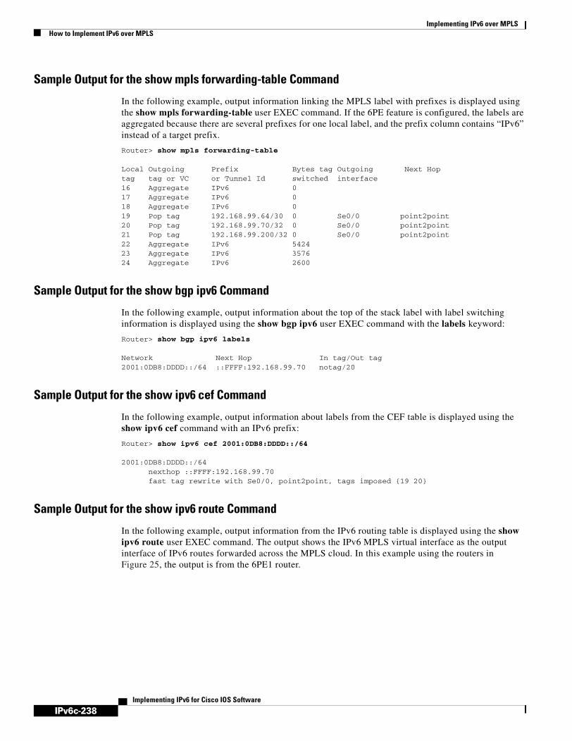
IPv6c-238
Implementing IPv6 over MPLSHow to Implement IPv6 over MPLS
Implementing IPv6 for Cisco IOS Software
Sample Output for the show mpls forwarding-table Command
In the following example, output information linking the MPLS label with prefixes is displayed using the show mpls forwarding-table user EXEC command. If the 6PE feature is configured, the labels are aggregated because there are several prefixes for one local label, and the prefix column contains “IPv6” instead of a target prefix.
Router> show mpls forwarding-table
Local Outgoing Prefix Bytes tag Outgoing Next Hop tag tag or VC or Tunnel Id switched interface 16 Aggregate IPv6 0 17 Aggregate IPv6 0 18 Aggregate IPv6 0 19 Pop tag 192.168.99.64/30 0 Se0/0 point2point 20 Pop tag 192.168.99.70/32 0 Se0/0 point2point 21 Pop tag 192.168.99.200/32 0 Se0/0 point2point 22 Aggregate IPv6 5424 23 Aggregate IPv6 3576 24 Aggregate IPv6 2600
Sample Output for the show bgp ipv6 Command
In the following example, output information about the top of the stack label with label switching information is displayed using the show bgp ipv6 user EXEC command with the labels keyword:
Router> show bgp ipv6 labels
Network Next Hop In tag/Out tag2001:0DB8:DDDD::/64 ::FFFF:192.168.99.70 notag/20
Sample Output for the show ipv6 cef Command
In the following example, output information about labels from the CEF table is displayed using the show ipv6 cef command with an IPv6 prefix:
Router> show ipv6 cef 2001:0DB8:DDDD::/64
2001:0DB8:DDDD::/64 nexthop ::FFFF:192.168.99.70 fast tag rewrite with Se0/0, point2point, tags imposed {19 20}
Sample Output for the show ipv6 route Command
In the following example, output information from the IPv6 routing table is displayed using the show ipv6 route user EXEC command. The output shows the IPv6 MPLS virtual interface as the output interface of IPv6 routes forwarded across the MPLS cloud. In this example using the routers in Figure 25, the output is from the 6PE1 router.

IPv6c-239
Implementing IPv6 over MPLSConfiguration Examples for IPv6 over MPLS
Implementing IPv6 for Cisco IOS Software
The 6PE2 router has advertised the IPv6 prefix of 2001:0DB8:dddd::/48 configured for the CE2 router and the next-hop address is the IPv4-compatible IPv6 address ::ffff:192.168.99.70, where 192.168.99.70 is the IPv4 address of the 6PE2 router.
Router> show ipv6 route
IPv6 Routing Table - 10 entriesCodes: C - Connected, L - Local, S - Static, R - RIP, B - BGPI1 - ISIS L1, I2 - ISIS L2, IA - ISIS interareaB 2001:0DB8:DDDD::/64 [200/0] via ::FFFF:192.168.99.70, IPv6-mplsB 2001:0DB8:DDDD::/64 [200/0] via ::FFFF:192.168.99.70, IPv6-mplsL 2001:0DB8:FFFF::1/128 [0/0] via ::, Ethernet0/0C 2001:0DB8:FFFF::/64 [0/0] via ::, Ethernet0/0S 2001:0DB8:FFFF::/48 [1/0] via 2001:0DB8:B00:FFFF::2, Ethernet0/0
Note For a description of each output display field, refer to the relevant show command in the IPv6 for Cisco IOS Command Reference.
Configuration Examples for IPv6 over MPLSThis section provides the following configuration example:
• 6PE Configuration Example, page 239
6PE Configuration ExampleThe following examples show configuration examples for three of the routers shown in Figure 25 and used in the “Specifying the Source Address Interface on a 6PE Router” and “Binding and Advertising the 6PE Label to Advertise Prefixes” sections.
Customer Edge Router
In the following example, serial interface 0/0 of the customer edge router—CE1 in Figure 25—is connected to the service provider and is assigned an IPv6 address. IPv6 is enabled and a default static route is installed using the IPv6 address of serial interface 0/0 of the 6PE1 router.
ip cef!ipv6 unicast-routing!interface Serial 0/0 description to_6PE1_router no ip address ipv6 address 2001:0DB8:FFFF::2/64!ipv6 route ::/0 Serial 0/0 FE80::210:XXXX:FEE1:1001

IPv6c-240
Implementing IPv6 over MPLSConfiguration Examples for IPv6 over MPLS
Implementing IPv6 for Cisco IOS Software
Provider Edge Router
The 6PE router—Router 6PE1 in Figure 25—is configured for both IPv4 and IPv6 traffic. Ethernet interface 0/0 is configured with an IPv4 address and is connected to a router in the core of the network—router P1 in Figure 25. Integrated IS-IS and TDP configurations on this router are similar to the P1 router.
Router 6PE1 exchanges IPv6 routing information with another 6PE router—Router 6PE2 in Figure 25— using internal BGP (iBGP) established over an IPv4 connection so that all the neighbor commands use the IPv4 address of the 6PE2 router. All the BGP peers are within autonomous system 65000, so synchronization with IGP is turned off for IPv4. In IPv6 address family configuration mode, synchronization is disabled by default.
IPv6 and CEFv6 are enabled, the 6PE2 neighbor is activated, and aggregate label binding and advertisement is enabled for IPv6 prefixes using the neighbor send-label command. Connected and static IPV6 routes are redistributed using BGP. If IPv6 packets are generated in the local router, the IPv6 address for MPLS processing will be the address of loopback interface 0.
In the following example, serial interface 0/0 connects to the customer and the IPv6 prefix delegated to the customer is 2001:0DB8:ffff::/48, which is determined from the service provider IPv6 prefix. A static route is configured to route IPv6 packets between the 6PE route and the CE router.
ip cefipv6 cefipv6 unicast-routing!mpls ipv6 source-interface Loopback0tag-switching tdp router-id Loopback0!interface Loopback0 ip address 192.168.99.5 255.255.255.255 ipv6 address 2001:0DB8:1000:1::1/64!interface Ethernet0/0 description to_P_router ip address 192.168.99.1 255.255.255.252 ip router isis tag-switching ip!interface Serial0/0 description to_CE_router no ip address ipv6 address 2001:0DB8:FFFF::1/64!router isis passive-interface Loopback0 net 49.0001.1921.6809.9005.00!router bgp 65000 no bgp default ipv4-unicast bgp log-neighbor-changes neighbor 192.168.99.70 remote-as 65000 neighbor 192.168.99.70 description to_6PE2 neighbor 192.168.99.70 update-source Loopback0 ! address-family ipv6 neighbor 192.168.99.70 activate neighbor 192.168.99.70 send-label network 2001:0DB8:FFFF::/48 exit-address-family!ipv6 route 2001:0DB8:FFFF::/48 Ethernet0/0 2001:0DB8:FFFF::2

IPv6c-241
Implementing IPv6 over MPLSWhere to Go Next
Implementing IPv6 for Cisco IOS Software
Core Router
In the following example, the router in the core of the network—Router P in Figure 25—is running MPLS, IS-IS, and IPv4 only. The Ethernet interfaces are configured with IPv4 address and are connected to the 6PE routers. IS-IS is the IGP for this network and the P1 and 6PE routers are in the same IS-IS area 49.0001. TDP and tag switching are enabled on both the Ethernet interfaces. CEF is enabled in global configuration mode.
ip cef!tag-switching tdp router-id Loopback0!interface Loopback0 ip address 192.168.99.200 255.255.255.255!interface Ethernet0/0 description to_6PE1 ip address 192.168.99.2 255.255.255.252 ip router isis tag-switching ip!interface Ethernet0/1 description to_6PE2 ip address 192.168.99.66 255.255.255.252 ip router isis tag-switching ip
router isis passive-interface Loopback0 net 49.0001.1921.6809.9200.00
Where to Go NextIf you want to further customize your MPLS network, refer to the Cisco IOS Switching Services Configuration Guide, Release 12.4.
Additional ReferencesFor additional information related to IPv6 over MPLS, see the following sections:
• Related Documents, page 242
• Standards, page 242
• MIBs, page 243
• RFCs, page 243
• Technical Assistance, page 243

IPv6c-242
Implementing IPv6 over MPLSAdditional References
Implementing IPv6 for Cisco IOS Software
Related Documents
Standards
Related Topic Document Title
MPLS configuration tasks “Configuring Multiprotocol Label Switching” chapter in the Cisco IOS Switching Services Configuration Guide, Release 12.4
MPLS commands: complete command syntax, command mode, defaults, usage guidelines, and examples
Cisco IOS Switching Services Command Reference, Release 12.4
IPv6 supported feature list Start Here: Cisco IOS Software Release Specifics for IPv6 Features
IPv6 commands: complete command syntax, command mode, defaults, usage guidelines, and examples
IPv6 for Cisco IOS Command Reference
IPv4 configuration and command reference information
Cisco IOS Release 12.4 Configuration Guides and Command References
Standards Title
Draft-ietf-ngtrans-bgp-tunnel-04.txt Connecting IPv6 Islands Across IPv4 Clouds with BGP

IPv6c-243
Implementing IPv6 over MPLSAdditional References
Implementing IPv6 for Cisco IOS Software
MIBs
RFCs
Technical Assistance
MIBs MIBs Link
No new or modified MIBs are supported by this feature, and support for existing MIBs has not been modified by this feature.
To locate and download MIBs for selected platforms, Cisco IOS releases, and feature sets, use Cisco MIB Locator found at the following URL:
http://www.cisco.com/go/mibs
RFCs Title
No new or modified RFCs are supported by this feature, and support for existing RFCs has not been modified by this feature.
—
Description Link
The Cisco Technical Support website contains thousands of pages of searchable technical content, including links to products, technologies, solutions, technical tips, and tools. Registered Cisco.com users can log in from this page to access even more content.
http://www.cisco.com/techsupport

IPv6c-244
Implementing IPv6 over MPLSAdditional References
Implementing IPv6 for Cisco IOS Software

IPv6c-245Implementing IPv6 for Cisco IOS Software
Implementing OSPF for IPv6
Implementing OSPF for IPv6 expands on OSPF to provide support for IPv6 routing prefixes. OSPF for IPv6 is described in RFC 2740. This module describes the concepts and tasks you need to implement OSPF for IPv6 on your network.
Finding Support Information for Platforms and Cisco IOS Software Images
Use Cisco Feature Navigator to find information about platform support and Cisco IOS software image support. Access Cisco Feature Navigator at http://www.cisco.com/go/fn. You must have an account on Cisco.com. If you do not have an account or have forgotten your username or password, click Cancel at the login dialog box and follow the instructions that appear.
Contents• Prerequisites for Implementing OSPF for IPv6, page 245
• Restrictions for Implementing OSPF for IPv6, page 246
• Information About Implementing OSPF for IPv6, page 246
• How to Implement OSPF for IPv6, page 251
• Configuration Examples for Implementing OSPF for IPv6, page 260
• Additional References, page 262
Prerequisites for Implementing OSPF for IPv6Before you enable Open Shortest Path First (OSPF) for IPv6 on an interface, you must do the following:
• Complete the OSPF network strategy and planning for your IPv6 network. For example, you must decide whether multiple areas are required.
• Enable IPv6 unicast routing.
• Enable IPv6 on the interface.
This document assumes that you are familiar with IPv4. Refer to the publications referenced in the “Related Documents” section for IPv4 configuration and command reference information. Table 11 identifies the earliest release for each early-deployment train in which the feature became available.

IPv6c-246
Implementing OSPF for IPv6Restrictions for Implementing OSPF for IPv6
Implementing IPv6 for Cisco IOS Software
Restrictions for Implementing OSPF for IPv6 • When running a dual-stack IP network with OSPF version 2 for IPv4 and OSPF for IPv6, be careful
when changing the defaults for commands used to enable OSPF for IPv6. Changing these defaults may affect your OSPF for IPv6 network, possibly adversely.
• Authentication is supported as of the 12.3(4)T release. Encryption will be supported in a later release.
Information About Implementing OSPF for IPv6To implement OSPF for IPv6, you need to understand the following concepts:
• How OSPF for IPv6 Works, page 247
• Comparison of OSPF for IPv6 and OSPF Version 2, page 247
• LSA Types for IPv6, page 248
• Force SPF in OSPF for IPv6, page 249
• Load Balancing in OSPF for IPv6, page 249
• Importing Addresses into OSPF for IPv6, page 250
• OSPF for IPv6 Customization, page 250
• OSPF for IPv6 Authentication Support with IPSec, page 250
Table 11 Minimum Required Cisco IOS Release
FeatureMinimum Required Cisco IOS Release by Release Train
OSPF Version 3 expands on OSPF Version 2 12.2(15)T, 12.0(24)S, 12.2(18)S, 12.3, 12.3(2)T, 12.4, 12.4(2)T, 12.2(28)SB
LSA types in OSPF for IPv6 12.2(15)T, 12.0(24)S, 12.2(18)S, 12.3, 12.3(2)T, 12.4, 12.4(2)T, 12.2(28)SB
NBMA interfaces in OSPF for IPv6 12.2(15)T, 12.0(24)S, 12.2(18)S, 12.3, 12.3(2)T, 12.4, 12.4(2)T, 12.2(28)SB
Force SPF in OSPF for IPv6 12.2(15)T, 12.0(24)S, 12.2(18)S, 12.3, 12.3(2)T, 12.4, 12.4(2)T, 12.2(28)SB
Load balancing in OSPF for IPv6 12.2(15)T, 12.0(24)S, 12.2(18)S, 12.3, 12.3(2)T, 12.4, 12.4(2)T, 12.2(28)SB
Addresses on an interface in OSPF for IPv6 12.2(15)T, 12.0(24)S, 12.2(18)S, 12.3, 12.3(2)T, 12.4, 12.4(2)T, 12.2(28)SB
OSPF for IPv6 authentication support with IPSec 12.3(4)T, 12.4, 12.4(2)T

IPv6c-247
Implementing OSPF for IPv6Information About Implementing OSPF for IPv6
Implementing IPv6 for Cisco IOS Software
How OSPF for IPv6 WorksOSPF is a routing protocol for IP. It is a link-state protocol, as opposed to a distance-vector protocol. Think of a link as being an interface on a networking device. A link-state protocol makes its routing decisions based on the states of the links that connect source and destination machines. The state of a link is a description of that interface and its relationship to its neighboring networking devices. The interface information includes the IPv6 prefix of the interface, the network mask, the type of network it is connected to, the routers connected to that network, and so on. This information is propagated in various type of link-state advertisements (LSAs).
A router’s collection of LSA data is stored in a link-state database. The contents of the database, when subjected to the Dijkstra algorithm, result in the creation of the OSPF routing table. The difference between the database and the routing table is that the database contains a complete collection of raw data; the routing table contains a list of shortest paths to known destinations via specific router interface ports.
OSPF version 3, which is described in RFC 2740, supports IPv6.
Comparison of OSPF for IPv6 and OSPF Version 2Much of the OSPF for IPv6 feature is the same as in OSPF version 2. OSPF version 3 for IPv6, which is described in RFC 2740, expands on OSPF version 2 to provide support for IPv6 routing prefixes and the larger size of IPv6 addresses.
In OSPF for IPv6, a routing process does not need to be explicitly created. Enabling OSPF for IPv6 on an interface will cause a routing process, and its associated configuration, to be created.
In OSPF for IPv6, each interface must be enabled using commands in interface configuration mode. This feature is different from OSPF version 2, in which interfaces are indirectly enabled using the router configuration mode.
When using a nonbroadcast multiaccess (NBMA) interface in OSPF for IPv6, users must manually configure the router with the list of neighbors. Neighboring routers are identified by their router ID.
In IPv6, users can configure many address prefixes on an interface. In OSPF for IPv6, all address prefixes on an interface are included by default. Users cannot select some address prefixes to be imported into OSPF for IPv6; either all address prefixes on an interface are imported, or no address prefixes on an interface are imported.
Unlike OSPF version 2, multiple instances of OSPF for IPv6 can be run on a link.
In OSPF for IPv6, it is possible that no IPv4 addresses will be configured on any interface. In this case, the user must use the router-id command to configure a router ID before the OSPF process will be started. A router ID is a 32-bit opaque number. OSPF version 2 takes advantage of the 32-bit IPv4 address to pick an IPv4 address as the router ID. If an IPv4 address does exist when OSPF for IPv6 is enabled on an interface, then that IPv4 address is used for the router ID. If more than one IPv4 address is available, a router ID is chosen using the same rules as for OSPF version 2.
OSPF automatically prefers a loopback interface over any other kind, and it chooses the highest IP address among all loopback interfaces. If no loopback interfaces are present, the highest IP address in the router is chosen. You cannot tell OSPF to use any particular interface.
For further information about configuring a router ID and the router-id command, refer to “Configuring OSPF” chapter of the Cisco IOS IP Configuration Guide and Cisco IOS IP Command Reference, Volume 2 of 4: Routing Protocols, Release 12.4.

IPv6c-248
Implementing OSPF for IPv6Information About Implementing OSPF for IPv6
Implementing IPv6 for Cisco IOS Software
LSA Types for IPv6The following list describes LSA types, each of which has a different purpose:
• Router LSAs (Type 1)—Describes the link state and costs of a router’s links to the area. These LSAs are flooded within an area only. The LSA indicates if the router is an Area Border Router (ABR) or Autonomous System Boundary Router (ASBR), and if it is one end of a virtual link. Type 1 LSAs are also used to advertise stub networks. In OSPF for IPv6, these LSAs have no address information and are network-protocol-independent. In OSPF for IPv6, router interface information may be spread across multiple router LSAs. Receivers must concatenate all router LSAs originated by a given router when running the SPF calculation.
• Network LSAs (Type 2)—Describes the link-state and cost information for all routers attached to the network. This LSA is an aggregation of all the link-state and cost information in the network. Only a designated router tracks this information and can generate a network LSA. In OSPF for IPv6, network LSAs have no address information and are network-protocol-independent.
• Interarea-prefix LSAs for ABRs (Type 3)—Advertises internal networks to routers in other areas (interarea routes). Type 3 LSAs may represent a single network or a set of networks summarized into one advertisement. Only ABRs generate summary LSAs. In OSPF for IPv6, addresses for these LSAs are expressed as prefix, prefix length instead of address, mask. The default route is expressed as a prefix with length 0.
• Interarea-router LSAs for ASBRs (Type 4)—Advertise the location of an ASBR. Routers that are trying to reach an external network use these advertisements to determine the best path to the next hop. ASBRs generate Type 4 LSAs.
• Autonomous system external LSAs (Type 5)—Redistributes routes from another AS, usually from a different routing protocol into OSPF. In OSPF for IPv6, addresses for these LSAs are expressed as prefix, prefix length instead of address, mask. The default route is expressed as a prefix with length 0.
• Link LSAs (Type 8)—Have local-link flooding scope and are never flooded beyond the link with which they are associated. Link LSAs provide the link-local address of the router to all other routers attached to the link, inform other routers attached to the link of a list of IPv6 prefixes to associate with the link, and allow the router to assert a collection of Options bits to associate with the network LSA that will be originated for the link.
• Intra-Area-Prefix LSAs (Type 9)—A router can originate multiple intra-area-prefix LSAs for each router or transit network, each with a unique link-state ID. The link-state ID for each intra-area-prefix LSA describes its association to either the router LSA or the network LSA and contains prefixes for stub and transit networks.
An address prefix occurs in almost all newly defined LSAs. The prefix is represented by three fields: PrefixLength, PrefixOptions, and Address Prefix. In OSPF for IPv6, addresses for these LSAs are expressed as prefix, prefix length instead of address, mask. The default route is expressed as a prefix with length 0. Type 3 and Type 9 LSAs carry all IPv6 prefix information that, in IPv4, is included in router LSAs and network LSAs. The Options field in certain LSAs (router LSAs, network LSAs, interarea-router LSAs, and link LSAs) has been expanded to 24 bits to provide support for OSPF in IPv6.
In OSPF for IPv6, the sole function of link-state ID in interarea-prefix LSAs, interarea-router LSAs, and autonomous-system external LSAs is to identify individual pieces of the link-state database. All addresses or router IDs that are expressed by the link-state ID in OSPF version 2 are carried in the body of the LSA in OSPF for IPv6.

IPv6c-249
Implementing OSPF for IPv6Information About Implementing OSPF for IPv6
Implementing IPv6 for Cisco IOS Software
The link-state ID in network LSAs and link LSAs is always the interface ID of the originating router on the link being described. For this reason, network LSAs and link LSAs are now the only LSAs whose size cannot be limited. A network LSA must list all routers connected to the link, and a link LSA must list all of the address prefixes of a router on the link.
NBMA in OSPF for IPv6
On NBMA networks, the designated router (DR) or backup DR (BDR) performs the LSA flooding. On point-to-point networks, flooding simply goes out an interface directly to a neighbor.
Routers that share a common segment (Layer 2 link between two interfaces) become neighbors on that segment. OSPF uses the Hello protocol, periodically sending hello packets out each interface. Routers become neighbors when they see themselves listed in the neighbor’s hello packet. After two routers become neighbors, they may proceed to exchange and synchronize their databases, which creates an adjacency. Not all neighboring routers have an adjacency.
On point-to-point and point-to-multipoint networks, the software floods routing updates to immediate neighbors. There is no DR or BDR; all routing information is flooded to each networking device.
On broadcast or NBMA segments only, OSPF minimizes the amount of information being exchanged on a segment by choosing one router to be a DR and one router to be a BDR. Thus, the routers on the segment have a central point of contact for information exchange. Instead of each router exchanging routing updates with every other router on the segment, each router exchanges information with the DR and BDR. The DR and BDR relay the information to the other routers.
The software looks at the priority of the routers on the segment to determine which routers will be the DR and BDR. The router with the highest priority is elected the DR. If there is a tie, then the router with the higher router ID takes precedence. After the DR is elected, the BDR is elected the same way. A router with a router priority set to zero is ineligible to become the DR or BDR.
When using NBMA in OSPF for IPv6, you cannot automatically detect neighbors. On an NBMA interface, you must configure your neighbors manually using interface configuration mode.
Force SPF in OSPF for IPv6When the process keyword is used with the clear ipv6 ospf command, the OSPF database is cleared and repopulated, and then the shortest path first (SPF) algorithm is performed. When the force-spf keyword is used with the clear ipv6 ospf command, the OSPF database is not cleared before the SPF algorithm is performed.
Load Balancing in OSPF for IPv6When a router learns multiple routes to a specific network via multiple routing processes (or routing protocols), it installs the route with the lowest administrative distance in the routing table. Sometimes the router must select a route from among many learned via the same routing process with the same administrative distance. In this case, the router chooses the path with the lowest cost (or metric) to the destination. Each routing process calculates its cost differently and the costs may need to be manipulated in order to achieve load balancing.
OSPF performs load balancing automatically in the following way. If OSPF finds that it can reach a destination through more than one interface and each path has the same cost, it installs each path in the routing table. The only restriction on the number of paths to the same destination is controlled by the maximum-paths command. The default maximum paths is 16, and the range is from 1 to 64.

IPv6c-250
Implementing OSPF for IPv6Information About Implementing OSPF for IPv6
Implementing IPv6 for Cisco IOS Software
Importing Addresses into OSPF for IPv6When importing the set of addresses specified on an interface on which OSPF for IPv6 is running into OSPF for IPv6, users cannot select specific addresses to be imported. Either all addresses are imported, or no addresses are imported.
OSPF for IPv6 CustomizationYou can customize OSPF for IPv6 for your network, but you likely will not need to do so. The defaults for OSPF in IPv6 are set to meet the requirements of most customers and features. If you must change the defaults, refer to the IPv4 configuration guide and the IPv6 command reference to find the appropriate syntax.
Caution Be careful when changing the defaults. Changing defaults will affect your OSPF for IPv6 network, possibly adversely.
OSPF for IPv6 Authentication Support with IPSecIn order to ensure that OSPF for IPv6 packets are not altered and re-sent to the router, causing the router to behave in a way not desired by its managers, OSPF for IPv6 packets must be authenticated. OSPF for IPv6 uses the IP Security (IPSec) secure socket application program interface (API) to add authentication to OSPF for IPv6 packets. This API has been extended to provide support for IPv6.
OSPF for IPv6 requires the use of IPSec to enable authentication. Crypto images are required to use authentication, because only crypto images include the IPSec API needed for use with OSPF for IPv6.
In OSPF for IPv6, authentication fields have been removed from OSPF headers. When OSPF runs on IPv6, OSPF relies on the IPv6 authentication header (AH) and IPv6 encapsulating security payload (ESP) to ensure integrity, authentication, and confidentiality of routing exchanges. IPv6 AH and ESP extension headers can be used to provide authentication and confidentiality to OSPF for IPv6.
To configure IPSec, users configure a security policy, which is a combination of the security policy index (SPI) and the key (the key creates and validates the Message Digest 5 [MD5] value). IPSec for OSPF for IPv6 can be configured on an interface or on an OSPF area. For higher security, users should configure a different policy on each interface configured with IPSec. If a user configures IPSec for an OSPF area, the policy is applied to all of the interfaces in that area, except for the interfaces that have IPSec configured directly. Once IPSec is configured for OSPF for IPv6, IPSec is invisible to the user.
The secure socket API is used by applications to secure traffic. The API needs to allow the application to open, listen, and close secure sockets. The binding between the application and the secure socket layer also allows the secure socket layer to inform the application of changes to the socket, such as connection open and close events. The secure socket API is able to identify the socket; that is, it can identify the local and remote addresses, masks, ports, and protocol that carry the traffic requiring security.
Each interface has a secure socket state, which can be one of the following:
• NULL: Do not create a secure socket for the interface if authentication is configured for the area.
• DOWN: Authentication has been configured for the interface (or the area that contains the interface), but OSPF has not received a CRYPTO_SS_SOCKET_UP message from IPSec.
• UP: OSPF has received a CRYPTO_SS_SOCKET_UP message from IPSec.

IPv6c-251
Implementing OSPF for IPv6How to Implement OSPF for IPv6
Implementing IPv6 for Cisco IOS Software
• CLOSING: The secure socket for the interface has been closed. A new socket may be opened for the interface, in which case the current secure socket makes the transition to the DOWN state. Otherwise, the interface will become UNCONFIGURED.
• UNCONFIGURED: Authentication is not configured on the interface.
OSPF will not send or accept packets while in the DOWN state.
For further information on IPSec and how to implement it, refer to Implementing Security for IPv6.
How to Implement OSPF for IPv6This section contains the following procedures:
• Enabling OSPF for IPv6 on an Interface, page 251 (required)
• Defining an OSPF for IPv6 Area Range, page 252 (optional)
• Configuring IPSec on OSPF for IPv6, page 253 (optional)
• Configuring NBMA Interfaces, page 255 (optional)
• Forcing an SPF Calculation, page 256 (optional)
• Verifying OSPF for IPv6 Configuration and Operation, page 257 (optional)
Enabling OSPF for IPv6 on an InterfaceThis task explains how to enable OSPF for IPv6 routing and configure OSPF for IPv6 on each interface. By default, OSPF for IPv6 routing is disabled and OSPF for IPv6 is not configured on an interface.
SUMMARY STEPS
1. enable
2. configure terminal
3. interface type number
4. ipv6 ospf process-id area area-id [instance instance-id]
DETAILED STEPS
Command or Action Purpose
Step 1 enable
Example:Router> enable
Enables privileged EXEC mode.
• Enter your password if prompted.
Step 2 configure terminal
Example:Router# configure terminal
Enters global configuration mode.

IPv6c-252
Implementing OSPF for IPv6How to Implement OSPF for IPv6
Implementing IPv6 for Cisco IOS Software
Defining an OSPF for IPv6 Area RangeThe cost of the summarized routes will be the highest cost of the routes being summarized. For example, if the following routes are summarized:
OI 2001:0DB8:0:0:7::/64 [110/20] via FE80::A8BB:CCFF:FE00:6F00, Ethernet0/0OI 2001:0DB8:0:0:8::/64 [110/100] via FE80::A8BB:CCFF:FE00:6F00, Ethernet0/0OI 2001:0DB8:0:0:9::/64 [110/20] via FE80::A8BB:CCFF:FE00:6F00, Ethernet0/0
they becomes one summarized route, as follows:
OI 2001:0DB8::/48 [110/100] via FE80::A8BB:CCFF:FE00:6F00, Ethernet0/0
This task explains how to consolidate or summarize routes for an OSPF area.
Prerequisites
OSPF for IPv6 routing must be enabled.
SUMMARY STEPS
1. enable
2. configure terminal
3. ipv6 router ospf process-id
4. area area-id range {ipv6-prefix / prefix-length} [advertise | not-advertise] [cost cost]
Step 3 interface type number
Example:Router(config)# interface ethernet 0/0
Specifies an interface type and number, and places the router in interface configuration mode.
Step 4 ipv6 ospf process-id area area-id [instance instance-id]
Example:Router(config-if)# ipv6 ospf 1 area 0
Enables OSPF for IPv6 on an interface.
Command or Action Purpose

IPv6c-253
Implementing OSPF for IPv6How to Implement OSPF for IPv6
Implementing IPv6 for Cisco IOS Software
DETAILED STEPS
Configuring IPSec on OSPF for IPv6Once you have configured OSPF for IPv6 and decide on your authentication, you must define the security policy on each of the routers within the group. The security policy consists of the combination of the key and the SPI. To define a security policy, you must define an SPI and a key.
You can configure authentication either on an interface or in an OSPF area. When you define an area, it then finds all the interfaces in the area and applies authentication to all the interfaces. For higher security, use a different authentication on each interface.
The following tasks explain how to configure authentication on an interface or in an OSPF area.
• Defining Authentication on an Interface, page 253
• Defining Authentication in an OSPF Area, page 254
Defining Authentication on an Interface
This task explains how to define authentication on an interface.
Prerequisites
Before you configure IPSec on an interface, you must configure OSPF for IPv6 on that interface.
SUMMARY STEPS
1. enable
2. configure terminal
Command or Action Purpose
Step 1 enable
Example:Router> enable
Enables privileged EXEC mode.
• Enter your password if prompted.
Step 2 configure terminal
Example:Router# configure terminal
Enters global configuration mode.
Step 3 ipv6 router ospf process-id
Example:Router(config)# ipv6 router ospf 1
Enables OSPF router configuration mode.
Step 4 area area-id range {ipv6-prefix/prefix-length} [advertise | not-advertise] [cost cost]
Example:Router(config-rtr)# area range 1 2001:0DB8::/48
Consolidates and summarizes routes at an area boundary.
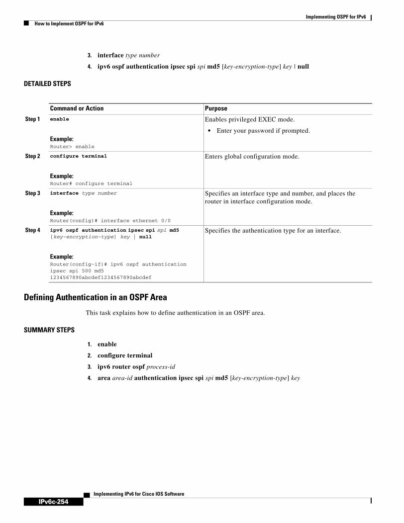
IPv6c-254
Implementing OSPF for IPv6How to Implement OSPF for IPv6
Implementing IPv6 for Cisco IOS Software
3. interface type number
4. ipv6 ospf authentication ipsec spi spi md5 [key-encryption-type] key | null
DETAILED STEPS
Defining Authentication in an OSPF Area
This task explains how to define authentication in an OSPF area.
SUMMARY STEPS
1. enable
2. configure terminal
3. ipv6 router ospf process-id
4. area area-id authentication ipsec spi spi md5 [key-encryption-type] key
Command or Action Purpose
Step 1 enable
Example:Router> enable
Enables privileged EXEC mode.
• Enter your password if prompted.
Step 2 configure terminal
Example:Router# configure terminal
Enters global configuration mode.
Step 3 interface type number
Example:Router(config)# interface ethernet 0/0
Specifies an interface type and number, and places the router in interface configuration mode.
Step 4 ipv6 ospf authentication ipsec spi spi md5 [key-encryption-type] key | null
Example:Router(config-if)# ipv6 ospf authentication ipsec spi 500 md5 1234567890abcdef1234567890abcdef
Specifies the authentication type for an interface.

IPv6c-255
Implementing OSPF for IPv6How to Implement OSPF for IPv6
Implementing IPv6 for Cisco IOS Software
DETAILED STEPS
Configuring NBMA InterfacesYou can customize OSPF for IPv6 in your network to use NBMA interfaces. OSPF for IPv6 cannot automatically detect neighbors over NBMA interfaces. On an NBMA interface, you must configure your neighbors manually using interface configuration mode. This task explains how to configure NBMA interfaces.
Prerequisites
Before you configure NBMA interfaces, you must perform the following tasks:
• Configure your network to be an NBMA network
• Identify each neighbor
Restrictions
• You cannot automatically detect neighbors when using NBMA interfaces. You must manually configure your router to detect neighbors when using an NBMA interface.
• When configuring the ipv6 ospf neighbor command, the IPv6 address used must be the link-local address of the neighbor.
SUMMARY STEPS
1. enable
Command or Action Purpose
Step 1 enable
Example:Router> enable
Enables privileged EXEC mode.
• Enter your password if prompted.
Step 2 configure terminal
Example:Router# configure terminal
Enters global configuration mode.
Step 3 ipv6 router ospf process-id
Example:Router(config)# ipv6 router ospf 1
Enables OSPF router configuration mode.
Step 4 area area-id authentication ipsec spi spi md5 [key-encryption-type] key
Example:Router(config-rtr)# area 1 authentication ipsec spi 678 md5 1234567890ABCDEF1234567890ABCDEF
Enables authentication for an OSPF area.

IPv6c-256
Implementing OSPF for IPv6How to Implement OSPF for IPv6
Implementing IPv6 for Cisco IOS Software
2. configure terminal
3. interface type number
4. frame-relay map ipv6 ipv6-address dlci [broadcast] [cisco] [ietf] [payload-compression {packet-by-packet | frf9 stac [hardware-options] | data-stream stac [hardware-options]}]
5. ipv6 ospf neighbor ipv6-address [priority number] [poll-interval seconds] [cost number] [database-filter all out]
DETAILED STEPS
Forcing an SPF CalculationThis task explains how to start the SPF algorithm without first clearing the OSPF database.
SUMMARY STEPS
1. enable
Command or Action Purpose
Step 1 enable
Example:Router> enable
Enables privileged EXEC mode.
• Enter your password if prompted.
Step 2 configure terminal
Example:Router# configure terminal
Enters global configuration mode.
Step 3 interface type number
Example:Router(config)# interface serial 0
Specifies an interface type and number, and places the router in interface configuration mode.
Step 4 frame-relay map ipv6 ipv6-address dlci [broadcast] [cisco] [ietf] [payload-compression {packet-by-packet | frf9 stac [hardware-options] | data-stream stac [hardware-options]}]
Example:Router(config-if)# frame-relay map ipv6 FE80::A8BB:CCFF:FE00:C01 120
Defines the mapping between a destination IPv6 address and the data-link connection identifier (DLCI) used to connect to the destination address.
• In this example, the NBMA link is frame relay. For other kinds of NBMA links, different mapping commands are used.
Step 5 ipv6 ospf neighbor ipv6-address [priority number] [poll-interval seconds] [cost number] [database-filter all out]
Example:Router(config-if) ipv6 ospf neighbor FE80::A8BB:CCFF:FE00:C01
Configures an OSPF for IPv6 neighboring router.

IPv6c-257
Implementing OSPF for IPv6How to Implement OSPF for IPv6
Implementing IPv6 for Cisco IOS Software
2. clear ipv6 ospf [process-id] {process | force-spf | redistribution | counters [neighbor [neighbor-interface]]}
Verifying OSPF for IPv6 Configuration and OperationThis task explains how to display information to verify the configuration and operation of OSPF for IPv6.
SUMMARY STEPS
1. enable
2. show ipv6 ospf [process-id] [area-id] interface [interface-type interface-number]
3. show ipv6 ospf [process-id] [area-id]
4. show crypto ipsec policy [name policy-name]
5. show crypto ipsec sa ipv6 [interface-type interface-number] [detailed]
DETAILED STEPS
Command or Action Purpose
Step 1 enable
Example:Router> enable
Enables privileged EXEC mode.
• Enter your password if prompted.
Step 2 clear ipv6 ospf [process-id] {process | force-spf | redistribution | counters [neighbor [neighbor-interface]]}
Example:Router# clear ipv6 ospf force-spf
Clears the OSPF state based on the OSPF routing process ID.
Command or Action Purpose
Step 1 enable
Example:Router> enable
Enables privileged EXEC mode.
• Enter your password if prompted.
Step 2 show ipv6 ospf [process-id] [area-id] interface [interface-type interface-number]
Example:Router# show ipv6 ospf interface
Displays OSPF-related interface information.
Step 3 show ipv6 ospf [process-id] [area-id]
Example:Router# show ipv6 ospf
Displays general information about OSPF routing processes.

IPv6c-258
Implementing OSPF for IPv6How to Implement OSPF for IPv6
Implementing IPv6 for Cisco IOS Software
Examples
This section provides the following output examples:
• Sample Output for the show ipv6 ospf interface Command, page 258
• Sample Output for the show ipv6 ospf Command, page 259
• Sample Output for the show crypto ipsec policy Command, page 259
• Sample Output for the show crypto ipsec sa ipv6 Command, page 259
Sample Output for the show ipv6 ospf interface Command
The following is sample output from the show ipv6 ospf interface command:
Router# show ipv6 ospf interface
ATM3/0 is up, line protocol is up Link Local Address FE80::205:5FFF:FED3:5808, Interface ID 13 Area 1, Process ID 1, Instance ID 0, Router ID 172.16.3.3 Network Type POINT_TO_POINT, Cost: 1 Transmit Delay is 1 sec, State POINT_TO_POINT, Timer intervals configured, Hello 10, Dead 40, Wait 40, Retransmit 5 Hello due in 00:00:06 Index 1/2/2, flood queue length 0 Next 0x0(0)/0x0(0)/0x0(0) Last flood scan length is 12, maximum is 12 Last flood scan time is 0 msec, maximum is 0 msec Neighbor Count is 1, Adjacent neighbor count is 1 Adjacent with neighbor 172.16.4.4 Suppress hello for 0 neighbor(s)FastEthernet0/0 is up, line protocol is up
Link Local Address FE80::205:5FFF:FED3:5808, Interface ID 3 Area 1, Process ID 1, Instance ID 0, Router ID 172.16.3.3 Network Type BROADCAST, Cost: 1 Transmit Delay is 1 sec, State BDR, Priority 1 Designated Router (ID) 172.16.6.6, local address FE80::205:5FFF:FED3:6408 Backup Designated router (ID) 172.16.3.3, local address FE80::205:5FFF:FED3:5808 Timer intervals configured, Hello 10, Dead 40, Wait 40, Retransmit 5 Hello due in 00:00:05 Index 1/1/1, flood queue length 0 Next 0x0(0)/0x0(0)/0x0(0) Last flood scan length is 12, maximum is 12 Last flood scan time is 0 msec, maximum is 0 msec Neighbor Count is 1, Adjacent neighbor count is 1 Adjacent with neighbor 172.16.6.6 (Designated Router) Suppress hello for 0 neighbor(s)
Step 4 show crypto ipsec policy [name policy-name]
Example:Router# show crypto ipsec policy
Displays the parameters for each IPSec parameter.
Step 5 show crypto ipsec sa ipv6 [interface-type interface-number] [detailed]
Example:Router# show crypto ipsec sa ipv6
Displays the settings used by current security associations (SAs).
Command or Action Purpose

IPv6c-259
Implementing OSPF for IPv6How to Implement OSPF for IPv6
Implementing IPv6 for Cisco IOS Software
Sample Output for the show ipv6 ospf Command
The following is sample output from the show ipv6 ospf command:
Router# show ipv6 ospf
Routing Process "ospfv3 1" with ID 172.16.3.3It is an autonomous system boundary routerRedistributing External Routes from,
staticSPF schedule delay 5 secs, Hold time between two SPFs 10 secsMinimum LSA interval 5 secs. Minimum LSA arrival 1 secsLSA group pacing timer 240 secsInterface flood pacing timer 33 msecsRetransmission pacing timer 66 msecsNumber of external LSA 1. Checksum Sum 0x218D Number of areas in this router is 1. 1 normal 0 stub 0 nssa
Area 1Number of interfaces in this area is 2SPF algorithm executed 9 timesNumber of LSA 15. Checksum Sum 0x67581 Number of DCbitless LSA 0Number of indication LSA 0Number of DoNotAge LSA 0Flood list length 0
Sample Output for the show crypto ipsec policy Command
The following is sample output from the show crypto ipsec policy command:
Router# show crypto ipsec policy
Crypto IPsec client security policy data
Policy name: OSPFv3-1-1000Policy refcount: 1Inbound AH SPI: 1000 (0x3E8)Outbound AH SPI: 1000 (0x3E8)Inbound AH Key: 1234567890ABCDEF1234567890ABCDEFOutbound AH Key: 1234567890ABCDEF1234567890ABCDEFTransform set: ah-md5-hmac
Sample Output for the show crypto ipsec sa ipv6 Command
The following is sample output from the show crypto ipsec sa ipv6 command:
Router# show crypto ipsec sa ipv6
IPv6 IPsec SA info for interface Ethernet0/0
protected policy name:OSPFv3-1-1000 IPsec created ACL name:Ethernet0/0-ipsecv6-ACL
local ident (addr/prefixlen/proto/port):(FE80::/10/89/0) remote ident (addr/prefixlen/proto/port):(::/0/89/0) current_peer::: PERMIT, flags={origin_is_acl,} #pkts encaps:21, #pkts encrypt:0, #pkts digest:21 #pkts decaps:20, #pkts decrypt:0, #pkts verify:20 #pkts compressed:0, #pkts decompressed:0 #pkts not compressed:0, #pkts compr. failed:0 #pkts not decompressed:0, #pkts decompress failed:0 #send errors 0, #recv errors 0
local crypto endpt. ::, remote crypto endpt. :: path mtu 1500, media mtu 1500

IPv6c-260
Implementing OSPF for IPv6Configuration Examples for Implementing OSPF for IPv6
Implementing IPv6 for Cisco IOS Software
current outbound spi:0x3E8(1000)
inbound ESP SAs:
inbound AH SAs: spi:0x3E8(1000) transform:ah-md5-hmac , in use settings ={Transport, } slot:0, conn_id:2000, flow_id:1, crypto map:N/R no sa timing (manual-keyed) replay detection support:N
inbound PCP SAs:
outbound ESP SAs:
outbound AH SAs: spi:0x3E8(1000) transform:ah-md5-hmac , in use settings ={Transport, } slot:0, conn_id:2001, flow_id:2, crypto map:N/R no sa timing (manual-keyed) replay detection support:N
outbound PCP SAs:
What to Do Next
For output examples of the commands used to verify OSPF for IPv6 configuration and operation, refer to the IPv6 for Cisco IOS Command Reference.
Configuration Examples for Implementing OSPF for IPv6This section provides the following configuration examples:
• Enabling OSPF for IPv6 on an Interface Configuration: Example, page 260
• Defining an OSPF for IPv6 Area Range: Example, page 260
• Defining Authentication on an Interface: Example, page 261
• Defining Authentication in an OSPF Area: Example, page 261
• Configuring NBMA Interfaces Configuration: Example, page 261
• Forcing SPF Configuration: Example, page 262
Enabling OSPF for IPv6 on an Interface Configuration: ExampleThe following example configures an OSPF routing process 109 to run on the interface and puts it in area 1:
ipv6 ospf 109 area 1
Defining an OSPF for IPv6 Area Range: ExampleThe following example specifies an OSPF for IPv6 area range:

IPv6c-261
Implementing OSPF for IPv6Configuration Examples for Implementing OSPF for IPv6
Implementing IPv6 for Cisco IOS Software
interface Ethernet7/0 ipv6 address 2001:0DB8:0:0:7::/64 eui-64 ipv6 enable ipv6 ospf 1 area 1!interface Ethernet8/0 ipv6 address 2001:0DB8:0:0:8::/64 eui-64 ipv6 enable ipv6 ospf 1 area 1!interface Ethernet9/0 ipv6 address 2001:0DB8:0:0:9::/64 eui-64 ipv6 enable ipv6 ospf 1 area 1!ipv6 router ospf 1 router-id 10.11.11.1 area 1 range 2001:0DB8::/48
Defining Authentication on an Interface: ExampleThe following example defines authentication on the Ethernet 0/0 interface:
interface Ethernet0/0 ipv6 enable ipv6 ospf 1 area 0 ipv6 ospf authentication ipsec spi 500 md5 1234567890ABCDEF1234567890ABCDEF
interface Ethernet0/0 ipv6 enable ipv6 ospf authentication null ipv6 ospf 1 area 0
Defining Authentication in an OSPF Area: ExampleThe following example defines authentication on OSPF area 0:
ipv6 router ospf 1 router-id 11.11.11.1 area 0 authentication ipsec spi 1000 md5 1234567890ABCDEF1234567890ABCDEF
Configuring NBMA Interfaces Configuration: ExampleThe following example configures an OSPF neighboring router with the IPv6 address of FE80::A8BB:CCFF:FE00:C01.
interface serial 0ipv6 enableipv6 ospf 1 area 0encapsulation frame-relayframe-relay map ipv6 FE80::A8BB:CCFF:FE00:C01 120ipv6 ospf neighbor FE80::A8BB:CCFF:FE00:C01

IPv6c-262
Implementing OSPF for IPv6Additional References
Implementing IPv6 for Cisco IOS Software
Forcing SPF Configuration: ExampleThe following example triggers SPF to redo the SPF and repopulate the routing tables:
clear ipv6 ospf force-spf
Additional ReferencesThe following sections provide additional references related to Implementing OSPF for IPv6.
• Related Documents
• Standards
• MIBs
• RFCs
• Technical Assistance

IPv6c-263
Implementing OSPF for IPv6Additional References
Implementing IPv6 for Cisco IOS Software
Related Documents
Standards
MIBs
RFCs
Related Topic Document Title
OSPF for IPv4 tasks “Configuring OSPF” chapter of the Cisco IOS IP Configuration Guide, Release 12.4
OSPF for IPv4 commands Cisco IOS IP Command Reference, Volume 2 of 4: Routing Protocols, Release 12.4
Configuring a router ID in OSPF “Configuring OSPF” chapter of the Cisco IOS IP Configuration Guide
Cisco IOS IP Command Reference, Volume 2 of 4: Routing Protocols, Release 12.4
OSPF for IPv6 commands IPv6 for Cisco IOS Command Reference
IPv6 supported feature list Start Here: Cisco IOS Software Release Specifics for IPv6 Features
Getting IPv6 started Implementing Basic Connectivity for IPv6
IPSec for IPv6 Implementing Security for IPv6
Security configuration tasks (IPv4) Cisco IOS Security Configuration Guide
Security commands: complete command syntax, command mode, defaults, usage guidelines, and examples (IPv4)
Cisco IOS Security Command Reference
IPv4 configuration and command reference information
Cisco IOS Release 12.4 Configuration Guides and Command References
Standards Title
draft-ietf-ospf-ospfv3-auth-03.txt Authentication/Confidentiality for OSPFv3, August 2003
MIBs MIBs Link
• CISCO-IETF-IP-FORWARD-MIB
• CISCO-IETF-IP-MIB
To locate and download MIBs for selected platforms, Cisco IOS releases, and feature sets, use Cisco MIB Locator found at the following URL:
http://www.cisco.com/go/mibs
RFCs Title
RFC 2401 Security Architecture for the Internet Protocol
RFC 2402 IP Authentication Header
RFC 2740 OSPF for IPv6

IPv6c-264
Implementing OSPF for IPv6Additional References
Implementing IPv6 for Cisco IOS Software
Technical Assistance
Description Link
The Cisco Technical Support website contains thousands of pages of searchable technical content, including links to products, technologies, solutions, technical tips, and tools. Registered Cisco.com users can log in from this page to access even more content.
http://www.cisco.com/techsupport

IPv6c-265Implementing IPv6 for Cisco IOS Software
Implementing RIP for IPv6
This module describes how to configure Routing Information Protocol for IPv6. RIP is a distance-vector routing protocol that uses hop count as a routing metric. RIP is an Interior Gateway Protocol (IGP) most commonly used in smaller networks.
Finding Support Information for Platforms and Cisco IOS Software Images
Use Cisco Feature Navigator to find information about platform support and Cisco IOS software image support. Access Cisco Feature Navigator at http://www.cisco.com/go/fn. You must have an account on Cisco.com. If you do not have an account or have forgotten your username or password, click Cancel at the login dialog box and follow the instructions that appear.
Contents• Prerequisites for Implementing RIP for IPv6, page 265
• Information About Implementing RIP for IPv6, page 266
• How to Implement RIP for IPv6, page 266
• Configuration Examples for IPv6 RIP, page 277
• Where to Go Next, page 277
• Additional References, page 277
Prerequisites for Implementing RIP for IPv6• This module assumes that you are familiar with IPv6 addressing and basic configuration. Refer to
the Implementing Basic Connectivity for IPv6 module for more information.
• This module assumes that you are familiar with IPv4. Refer to the publications referenced in the “Related Documents” section for IPv4 configuration and command reference information, as needed.
Table 12 identifies the earliest release for each early-deployment train in which the feature became available.

IPv6c-266
Implementing RIP for IPv6Information About Implementing RIP for IPv6
Implementing IPv6 for Cisco IOS Software
Information About Implementing RIP for IPv6To configure IPv6 RIP, you need to understand the following concept:
• RIP for IPv6, page 266
RIP for IPv6 IPv6 RIP functions the same and offers the same benefits as RIP in IPv4. RIP enhancements for IPv6, detailed in RFC 2080, include support for IPv6 addresses and prefixes, and the use of the all-RIP-routers multicast group address FF02::9 as the destination address for RIP update messages. New commands specific to RIP in IPv6 were also added to the Cisco IOS command-line interface (CLI).
In the Cisco IOS software implementation of IPv6 RIP each IPv6 RIP process maintains a local routing table, referred to as a Routing Information Database (RIB). The IPv6 RIP RIB contains a set of best-cost IPv6 RIP routes learned from all its neighboring networking devices. If IPv6 RIP learns the same route from two different neighbors, but with different costs, it will store only the lowest cost route in the local RIB. The RIB also stores any expired routes that the RIP process is advertising to its neighbors running RIP. IPv6 RIP will try to insert every non-expired route from its local RIB into the master IPv6 RIB. If the same route has been learned from a different routing protocol with a better administrative distance than IPv6 RIP, the RIP route will not be added to the IPv6 RIB but the RIP route will still exist in the IPv6 RIP RIB.
How to Implement RIP for IPv6When configuring supported routing protocols in IPv6, you must create the routing process, enable the routing process on interfaces, and customize the routing protocol for your particular network.
Note The following sections describe the configuration tasks for creating an IPv6 RIP routing process and enabling the routing process on interfaces. The following sections do not provide in-depth information on customizing RIP because the protocol functions the same in IPv6 as it does in IPv4. Refer to the publications referenced in the “Related Documents” section for further IPv6 and IPv4 configuration and command reference information.
Table 12 Minimum Required Cisco IOS Release
FeatureMinimum Required Cisco IOS Release by Release Train
RIP enhancements for IPv6 12.2(2)T, 12.0(21)ST, 12.0(22)S, 12.2(14)S, 12.3, 12.3(2)T, 12.4, 12.4(2)T, 12.2(28)SB
Route redistribution 12.2(2)T, 12.0(21)ST, 12.0(22)S, 12.2(14)S, 12.3, 12.3(2)T, 12.4, 12.4(2)T, 12.2(28)SB

IPv6c-267
Implementing RIP for IPv6How to Implement RIP for IPv6
Implementing IPv6 for Cisco IOS Software
The tasks in the following sections explain how to configure IPv6 RIP. Each task in the list is identified as either required or optional:
This section contains the following procedures:
• Enabling IPv6 RIP, page 267 (required)
• Customizing IPv6 RIP, page 268 (optional)
• Redistributing Routes into an IPv6 RIP Routing Process, page 269 (optional)
• Configuring Tags for RIP Routes, page 270 (optional)
• Filtering IPv6 RIP Routing Updates, page 271 (optional)
• Verifying IPv6 RIP Configuration and Operation, page 273 (optional)
Enabling IPv6 RIPThis task explains how to create an IPv6 RIP process and enable the specified IPv6 RIP process on an interface.
Prerequisites
Before configuring the router to run IPv6 RIP, globally enable IPv6 using the ipv6 unicast-routing global configuration command, and enable IPv6 on any interfaces on which IPv6 RIP is to be enabled. For details on basic IPv6 connectivity tasks, refer to the Implementing Basic Connectivity for IPv6 module.
SUMMARY STEPS
1. enable
2. configure terminal
3. interface type number
4. ipv6 rip name enable
DETAILED STEPS
Command or Action Purpose
Step 1 enable
Example:Router> enable
Enables privileged EXEC mode.
• Enter your password if prompted.
Step 2 configure terminal
Example:Router# configure terminal
Enters global configuration mode.

IPv6c-268
Implementing RIP for IPv6How to Implement RIP for IPv6
Implementing IPv6 for Cisco IOS Software
If you want to set or change a global value, follow steps 1 and 2, and then use the optional ipv6 router rip name command in global configuration mode.
Customizing IPv6 RIPThis optional task explains how to configure the maximum numbers of equal-cost paths that IPv6 RIP will support, adjust the IPv6 RIP timers, and originate a default IPv6 route.
SUMMARY STEPS
1. enable
2. configure terminal
3. ipv6 router rip name
4. maximum-paths number-paths
5. exit
6. interface type number
7. ipv6 rip name default-information {only | originate} [metric metric-value]
DETAILED STEPS
Step 3 interface type number
Example:Router(config)# interface Ethernet 0/0
Specifies the interface type and number, and enters interface configuration mode.
Step 4 ipv6 rip name enable
Example:Router(config-if)# ipv6 rip process1 enable
Enables the specified IPv6 RIP routing process on an interface.
Command or Action Purpose
Command or Action Purpose
Step 1 enable
Example:Router> enable
Enables privileged EXEC mode.
• Enter your password if prompted.
Step 2 configure terminal
Example:Router# configure terminal
Enters global configuration mode.
Step 3 ipv6 router rip name
Example:Router(config)# ipv6 router rip cisco
Configures an IPv6 RIP routing process and enters router configuration mode for the IPv6 RIP routing process.
• Use the name argument to identify a specific IPv6 RIP routing process.
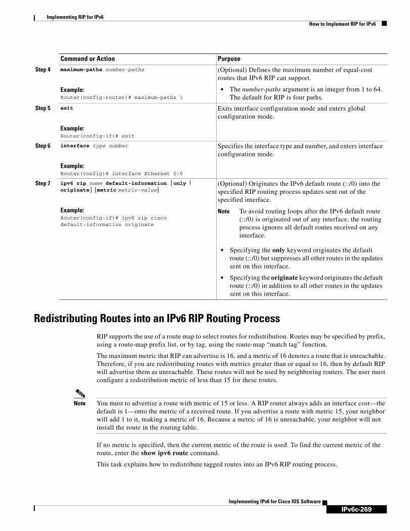
IPv6c-269
Implementing RIP for IPv6How to Implement RIP for IPv6
Implementing IPv6 for Cisco IOS Software
Redistributing Routes into an IPv6 RIP Routing ProcessRIP supports the use of a route map to select routes for redistribution. Routes may be specified by prefix, using a route-map prefix list, or by tag, using the route-map “match tag” function.
The maximum metric that RIP can advertise is 16, and a metric of 16 denotes a route that is unreachable. Therefore, if you are redistributing routes with metrics greater than or equal to 16, then by default RIP will advertise them as unreachable. These routes will not be used by neighboring routers. The user must configure a redistribution metric of less than 15 for these routes.
Note You must to advertise a route with metric of 15 or less. A RIP router always adds an interface cost—the default is 1—onto the metric of a received route. If you advertise a route with metric 15, your neighbor will add 1 to it, making a metric of 16. Because a metric of 16 is unreachable, your neighbor will not install the route in the routing table.
If no metric is specified, then the current metric of the route is used. To find the current metric of the route, enter the show ipv6 route command.
This task explains how to redistribute tagged routes into an IPv6 RIP routing process.
Step 4 maximum-paths number-paths
Example:Router(config-router)# maximum-paths 1
(Optional) Defines the maximum number of equal-cost routes that IPv6 RIP can support.
• The number-paths argument is an integer from 1 to 64. The default for RIP is four paths.
Step 5 exit
Example:Router(config-if)# exit
Exits interface configuration mode and enters global configuration mode.
Step 6 interface type number
Example:Router(config)# interface Ethernet 0/0
Specifies the interface type and number, and enters interface configuration mode.
Step 7 ipv6 rip name default-information {only | originate} [metric metric-value]
Example:Router(config-if)# ipv6 rip cisco default-information originate
(Optional) Originates the IPv6 default route (::/0) into the specified RIP routing process updates sent out of the specified interface.
Note To avoid routing loops after the IPv6 default route (::/0) is originated out of any interface, the routing process ignores all default routes received on any interface.
• Specifying the only keyword originates the default route (::/0) but suppresses all other routes in the updates sent on this interface.
• Specifying the originate keyword originates the default route (::/0) in addition to all other routes in the updates sent on this interface.
Command or Action Purpose

IPv6c-270
Implementing RIP for IPv6How to Implement RIP for IPv6
Implementing IPv6 for Cisco IOS Software
SUMMARY STEPS
1. enable
2. configure terminal
3. interface type number
4. ipv6 rip word enable
5. redistribute protocol [process-id] {level-1 | level-1-2 | level-2} [metric metric-value] [metric-type {internal | external}] [route-map map-name]
DETAILED STEPS
Configuring Tags for RIP RoutesWhen performing route redistribution, you can associate a numeric tag with a route. The tag is advertised with the route by RIP and will be installed along with the route in neighboring router’s routing table.
Command or Action Purpose
Step 1 enable
Example:Router> enable
Enables privileged EXEC mode.
• Enter your password if prompted.
Step 2 configure terminal
Example:Router# configure terminal
Enters global configuration mode.
Step 3 interface type number
Example:Router(config)# interface Ethernet 0/0
Specifies the interface type and number, and enters interface configuration mode.
Step 4 ipv6 rip word enable
Example:Router(config-if)# ipv6 router one enable
Enables an IPv6 Routing Information Protocol (RIP) routing process on an interface.
Step 5 redistribute protocol [process-id] {level-1 | level-1-2 | level-2} [metric metric-value] [metric-type {internal | external}] [route-map map-name]
Example:Router(config-router)# redistribute bgp 65001 route-map bgp-to-rip
Redistributes the specified routes into the IPv6 RIP routing process.
• The protocol argument can be one of the following keywords: bgp, connected, isis, rip, or static.
• The rip keyword and process-id argument specify an IPv6 RIP routing process.
Note The connected keyword refers to routes that are established automatically by assigning IPv6 addresses to an interface.

IPv6c-271
Implementing RIP for IPv6How to Implement RIP for IPv6
Implementing IPv6 for Cisco IOS Software
If you redistribute a tagged route (for example, a route in the IPv6 routing table that already has a tag) into RIP, then RIP will automatically advertise the tag with the route. If you use a redistribution route map to specify a tag, then RIP will use the route map tag in preference to the routing table tag.
The following task explains how to set route tags using a route map.
SUMMARY STEPS
1. enable
2. configure terminal
3. route-map map-tag [permit | deny] [sequence-number]
4. match ipv6 address {prefix-list prefix-list-name | access-list-name}
5. set tag value
DETAILED STEPS
Filtering IPv6 RIP Routing UpdatesRoute filtering using distribute lists provides control over the routes RIP receives and advertises. This control may be exercised globally or per interface.
Command or Action Purpose
Step 1 enable
Example:Router> enable
Enables privileged EXEC mode.
• Enter your password if prompted.
Step 2 configure terminal
Example:Router# configure terminal
Enters global configuration mode.
Step 3 route-map map-tag [permit | deny] [sequence-number]
Example:Router(config)# route-map bgp-to-rip permit 10
Defines a route map, and enters route-map configuration mode.
• Follow this step with a match command.
Step 4 match ipv6 address {prefix-list prefix-list-name | access-list-name}
Example:Router(config-route-map)# match ipv6 address prefix-list bgp-to-rip-flt
Specifies a list of IPv6 prefixes to be matched.
Step 5 set tag value
Example:Router(config-route-map)# set tag 4
Sets the tag value to associate with the redistributed routes.
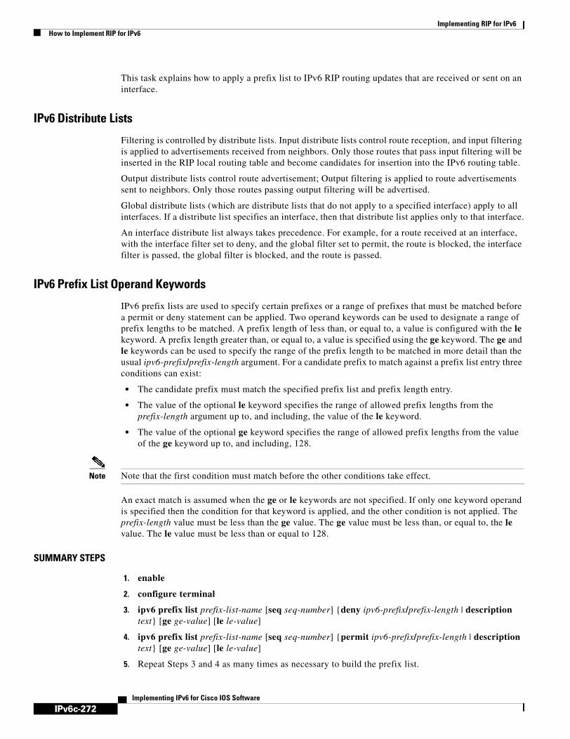
IPv6c-272
Implementing RIP for IPv6How to Implement RIP for IPv6
Implementing IPv6 for Cisco IOS Software
This task explains how to apply a prefix list to IPv6 RIP routing updates that are received or sent on an interface.
IPv6 Distribute Lists
Filtering is controlled by distribute lists. Input distribute lists control route reception, and input filtering is applied to advertisements received from neighbors. Only those routes that pass input filtering will be inserted in the RIP local routing table and become candidates for insertion into the IPv6 routing table.
Output distribute lists control route advertisement; Output filtering is applied to route advertisements sent to neighbors. Only those routes passing output filtering will be advertised.
Global distribute lists (which are distribute lists that do not apply to a specified interface) apply to all interfaces. If a distribute list specifies an interface, then that distribute list applies only to that interface.
An interface distribute list always takes precedence. For example, for a route received at an interface, with the interface filter set to deny, and the global filter set to permit, the route is blocked, the interface filter is passed, the global filter is blocked, and the route is passed.
IPv6 Prefix List Operand Keywords
IPv6 prefix lists are used to specify certain prefixes or a range of prefixes that must be matched before a permit or deny statement can be applied. Two operand keywords can be used to designate a range of prefix lengths to be matched. A prefix length of less than, or equal to, a value is configured with the le keyword. A prefix length greater than, or equal to, a value is specified using the ge keyword. The ge and le keywords can be used to specify the range of the prefix length to be matched in more detail than the usual ipv6-prefix/prefix-length argument. For a candidate prefix to match against a prefix list entry three conditions can exist:
• The candidate prefix must match the specified prefix list and prefix length entry.
• The value of the optional le keyword specifies the range of allowed prefix lengths from the prefix-length argument up to, and including, the value of the le keyword.
• The value of the optional ge keyword specifies the range of allowed prefix lengths from the value of the ge keyword up to, and including, 128.
Note Note that the first condition must match before the other conditions take effect.
An exact match is assumed when the ge or le keywords are not specified. If only one keyword operand is specified then the condition for that keyword is applied, and the other condition is not applied. The prefix-length value must be less than the ge value. The ge value must be less than, or equal to, the le value. The le value must be less than or equal to 128.
SUMMARY STEPS
1. enable
2. configure terminal
3. ipv6 prefix list prefix-list-name [seq seq-number] {deny ipv6-prefix/prefix-length | description text} [ge ge-value] [le le-value]
4. ipv6 prefix list prefix-list-name [seq seq-number] {permit ipv6-prefix/prefix-length | description text} [ge ge-value] [le le-value]
5. Repeat Steps 3 and 4 as many times as necessary to build the prefix list.

IPv6c-273
Implementing RIP for IPv6How to Implement RIP for IPv6
Implementing IPv6 for Cisco IOS Software
6. ipv6 router rip name
7. distribute-list prefix-list prefix-list-name {in | out} [interface-type interface-number]
DETAILED STEPS
Verifying IPv6 RIP Configuration and OperationA user may want to check IPv6 RIP configuration and operation. Some of the following scenarios may occur for which a user can then enable the following show and debug commands:
• “Why isn’t a certain route appearing in my IPv6 routing table?”
• “Am I receiving routes via RIP?”
Command or Action Purpose
Step 1 enable
Example:Router> enable
Enables privileged EXEC mode.
• Enter your password if prompted.
Step 2 configure terminal
Example:Router# configure terminal
Enters global configuration mode.
Step 3 ipv6 prefix list prefix-list-name [seq seq-number] {deny ipv6-prefix/prefix-length | description text} [ge ge-value] [le le-value]
Example:Router(config)# ipv6 prefix-list abc permit 2001:0db8::/16
Creates an entry in the IPv6 prefix list.
Step 4 ipv6 prefix list prefix-list-name [seq seq-number] {deny ipv6-prefix/prefix-length | description text} [ge ge-value] [le le-value]
Example:Router(config)# ipv6 prefix-list abc deny ::/0
Creates an entry in the IPv6 prefix list.
Step 5 Repeat Steps 3 and 4 as many times as necessary to build the prefix list.
—
Step 6 ipv6 router rip name
Example:Router(config)# ipv6 router rip cisco
Configures an IPv6 RIP routing process.
Step 7 distribute-list prefix-list prefix-list-name {in | out} [interface-type interface-number]
Example:Router(config-rtr-rip)# distribute-list prefix-list cisco in ethernet 0/0
Applies a prefix list to IPv6 RIP routing updates that are received or sent on an interface.

IPv6c-274
Implementing RIP for IPv6How to Implement RIP for IPv6
Implementing IPv6 for Cisco IOS Software
• “Is a certain route being filtered?”
• “Someone at a route site told me that I am not advertising a certain route. True?”
This task explains how to display information to verify the configuration and operation of IPv6 RIP.
SUMMARY STEPS
1. show ipv6 rip [name] [database | next-hops]
2. show ipv6 route [ipv6-address | ipv6-prefix/prefix-length | protocol]
3. enable
4. debug ipv6 rip [interface-type interface-number]
DETAILED STEPS
Output Examples
This section provides the following output examples:
• Sample Output for the show ipv6 rip Command, page 275
• Sample Output for the show ipv6 route Command, page 276
• Sample Output for the debug ipv6 rip Command, page 276
Command or Action Purpose
Step 1 show ipv6 rip [name] [database | next-hops]
Example:Router> show ipv6 rip cisco database
(Optional) Displays information about current IPv6 RIP processes.
• In this example, IPv6 RIP process database information is displayed for the specified IPv6 RIP process.
Step 2 show ipv6 route [ipv6-address | ipv6-prefix/prefix-length | protocol]
Example:Router> show ipv6 route rip
(Optional) Displays the current contents of the IPv6 routing table.
• In this example, only IPv6 RIP routes are displayed.
Step 3 enable
Example:Router> enable
Enables higher privilege levels, such as privileged EXEC mode.
• Enter your password if prompted.
Step 4 debug ipv6 rip [interface-type interface-number]
Example:Router# debug ipv6 rip
(Optional) Displays debugging messages for IPv6 RIP routing transactions.
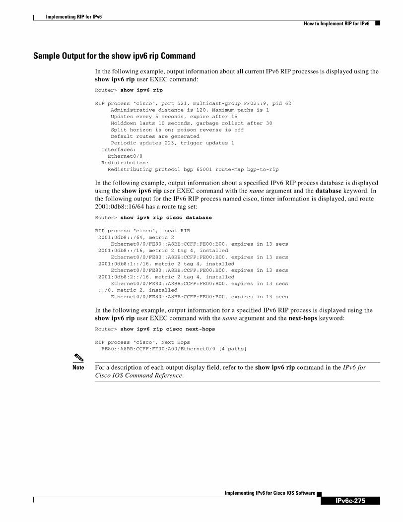
IPv6c-275
Implementing RIP for IPv6How to Implement RIP for IPv6
Implementing IPv6 for Cisco IOS Software
Sample Output for the show ipv6 rip Command
In the following example, output information about all current IPv6 RIP processes is displayed using the show ipv6 rip user EXEC command:
Router> show ipv6 rip
RIP process "cisco", port 521, multicast-group FF02::9, pid 62 Administrative distance is 120. Maximum paths is 1 Updates every 5 seconds, expire after 15 Holddown lasts 10 seconds, garbage collect after 30 Split horizon is on; poison reverse is off Default routes are generated Periodic updates 223, trigger updates 1 Interfaces: Ethernet0/0 Redistribution: Redistributing protocol bgp 65001 route-map bgp-to-rip
In the following example, output information about a specified IPv6 RIP process database is displayed using the show ipv6 rip user EXEC command with the name argument and the database keyword. In the following output for the IPv6 RIP process named cisco, timer information is displayed, and route 2001:0db8::16/64 has a route tag set:
Router> show ipv6 rip cisco database
RIP process "cisco", local RIB 2001:0db8::/64, metric 2 Ethernet0/0/FE80::A8BB:CCFF:FE00:B00, expires in 13 secs 2001:0db8::/16, metric 2 tag 4, installed Ethernet0/0/FE80::A8BB:CCFF:FE00:B00, expires in 13 secs 2001:0db8:1::/16, metric 2 tag 4, installed Ethernet0/0/FE80::A8BB:CCFF:FE00:B00, expires in 13 secs 2001:0db8:2::/16, metric 2 tag 4, installed Ethernet0/0/FE80::A8BB:CCFF:FE00:B00, expires in 13 secs ::/0, metric 2, installed Ethernet0/0/FE80::A8BB:CCFF:FE00:B00, expires in 13 secs
In the following example, output information for a specified IPv6 RIP process is displayed using the show ipv6 rip user EXEC command with the name argument and the next-hops keyword:
Router> show ipv6 rip cisco next-hops
RIP process "cisco", Next Hops FE80::A8BB:CCFF:FE00:A00/Ethernet0/0 [4 paths]
Note For a description of each output display field, refer to the show ipv6 rip command in the IPv6 for Cisco IOS Command Reference.
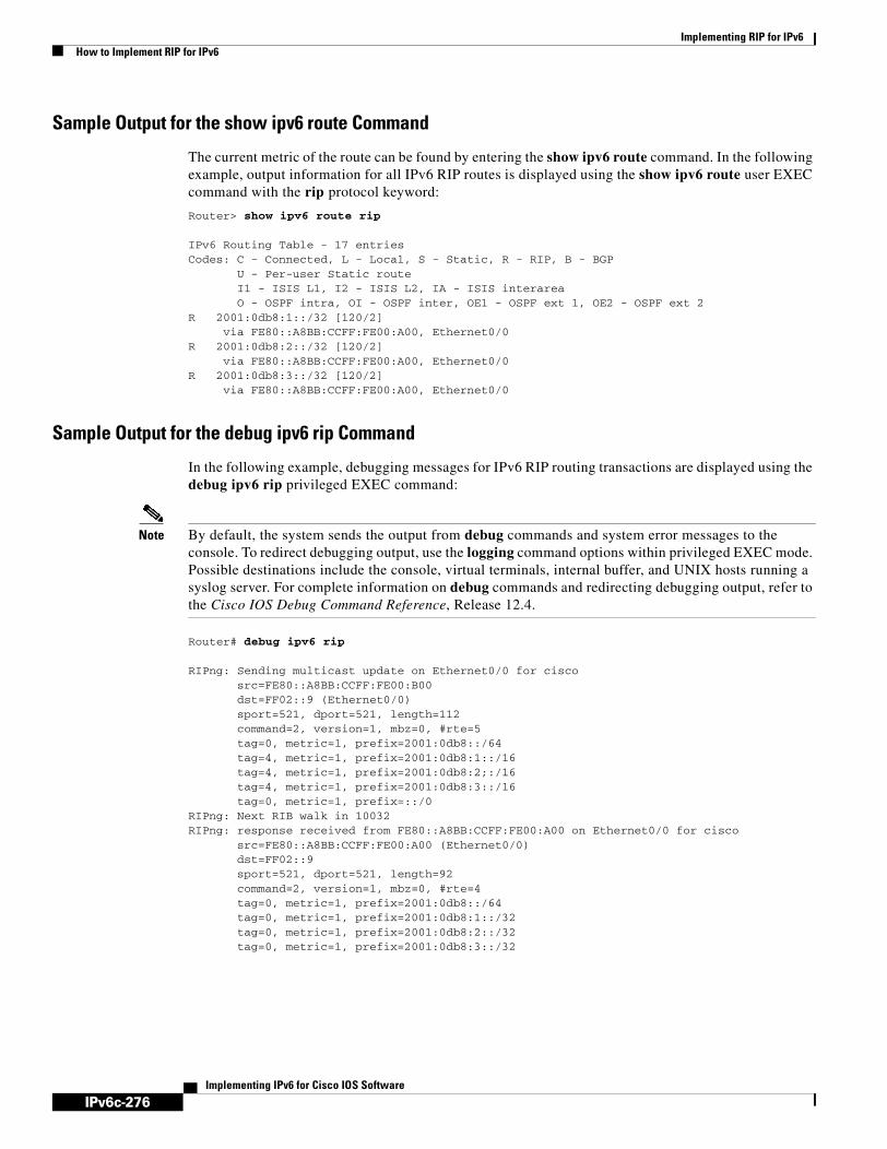
IPv6c-276
Implementing RIP for IPv6How to Implement RIP for IPv6
Implementing IPv6 for Cisco IOS Software
Sample Output for the show ipv6 route Command
The current metric of the route can be found by entering the show ipv6 route command. In the following example, output information for all IPv6 RIP routes is displayed using the show ipv6 route user EXEC command with the rip protocol keyword:
Router> show ipv6 route rip
IPv6 Routing Table - 17 entriesCodes: C - Connected, L - Local, S - Static, R - RIP, B - BGP U - Per-user Static route I1 - ISIS L1, I2 - ISIS L2, IA - ISIS interarea O - OSPF intra, OI - OSPF inter, OE1 - OSPF ext 1, OE2 - OSPF ext 2R 2001:0db8:1::/32 [120/2] via FE80::A8BB:CCFF:FE00:A00, Ethernet0/0R 2001:0db8:2::/32 [120/2] via FE80::A8BB:CCFF:FE00:A00, Ethernet0/0R 2001:0db8:3::/32 [120/2] via FE80::A8BB:CCFF:FE00:A00, Ethernet0/0
Sample Output for the debug ipv6 rip Command
In the following example, debugging messages for IPv6 RIP routing transactions are displayed using the debug ipv6 rip privileged EXEC command:
Note By default, the system sends the output from debug commands and system error messages to the console. To redirect debugging output, use the logging command options within privileged EXEC mode. Possible destinations include the console, virtual terminals, internal buffer, and UNIX hosts running a syslog server. For complete information on debug commands and redirecting debugging output, refer to the Cisco IOS Debug Command Reference, Release 12.4.
Router# debug ipv6 rip
RIPng: Sending multicast update on Ethernet0/0 for cisco src=FE80::A8BB:CCFF:FE00:B00 dst=FF02::9 (Ethernet0/0) sport=521, dport=521, length=112 command=2, version=1, mbz=0, #rte=5 tag=0, metric=1, prefix=2001:0db8::/64 tag=4, metric=1, prefix=2001:0db8:1::/16 tag=4, metric=1, prefix=2001:0db8:2;:/16 tag=4, metric=1, prefix=2001:0db8:3::/16 tag=0, metric=1, prefix=::/0RIPng: Next RIB walk in 10032RIPng: response received from FE80::A8BB:CCFF:FE00:A00 on Ethernet0/0 for cisco src=FE80::A8BB:CCFF:FE00:A00 (Ethernet0/0) dst=FF02::9 sport=521, dport=521, length=92 command=2, version=1, mbz=0, #rte=4 tag=0, metric=1, prefix=2001:0db8::/64 tag=0, metric=1, prefix=2001:0db8:1::/32 tag=0, metric=1, prefix=2001:0db8:2::/32 tag=0, metric=1, prefix=2001:0db8:3::/32

IPv6c-277
Implementing RIP for IPv6Configuration Examples for IPv6 RIP
Implementing IPv6 for Cisco IOS Software
Configuration Examples for IPv6 RIPThis section provides the following configuration examples:
• IPv6 RIP Configuration: Example, page 277
IPv6 RIP Configuration: ExampleIn the following example, the IPv6 RIP process named cisco is enabled on the router and on Ethernet interface 0/0. The IPv6 default route (::/0) is advertised in addition to all other routes in router updates sent on Ethernet interface 0/0. Additionally, BGP routes are redistributed into the RIP process named cisco according to a route map where routes that match a prefix list are also tagged. The number of parallel paths is set to one to allow the route tagging, and the IPv6 RIP timers are adjusted. A prefix list named eth0/0-in-flt filters inbound routing updates on Ethernet interface 0/0.
ipv6 router rip cisco maximum-paths 1 redistribute bgp 65001 route-map bgp-to-ripdistribute-list prefix-list eth0/0-in-flt in Ethernet0/0
!interface Ethernet0/0 ipv6 address 2001:0db8::/64 eui-64 ipv6 rip cisco enable ipv6 rip cisco default-information originate!ipv6 prefix-list bgp-to-rip-flt seq 10 deny 2001:0db8:3::/16 le 128ipv6 prefix-list bgp-to-rip-flt seq 20 permit 2001:0db8:1::/8 le 128!ipv6 prefix-list eth0/0-in-flt seq 10 deny ::/0ipv6 prefix-list eth0/0-in-flt seq 15 permit ::/0 le 128!route-map bgp-to-rip permit 10 match ipv6 address prefix-list bgp-to-rip-flt set tag 4
Where to Go NextIf you want to implement more IPv6 routing protocols, see the Implementing IS-IS for IPv6 or Implementing Multiprotocol BGP for IPv6 module.
Additional ReferencesFor additional information related to implementing RIP for IPv6, see the following sections:
• Related Documents, page 278
• Standards, page 278
• MIBs, page 278
• RFCs, page 278
• Technical Assistance, page 278

IPv6c-278
Implementing RIP for IPv6Additional References
Implementing IPv6 for Cisco IOS Software
Related Documents
Standards
MIBs
RFCs
Technical Assistance
Related Topic Document Title
RIP configuration tasks “Configuring Routing Information Protocol” chapter in the Cisco IOS IP Configuration Guide, Release 12.4
RIP commands: complete command syntax, command mode, defaults, usage guidelines, and examples
Cisco IOS IP Command Reference, Volume 2 of 3: Routing Protocols, Release 12.4
IPv6 supported feature list Start Here: Cisco IOS Software Release Specifics for IPv6 Features
IPv6 commands: complete command syntax, command mode, defaults, usage guidelines, and examples
IPv6 for Cisco IOS Command Reference
IPv4 configuration and command reference information
Cisco IOS Release 12.4 Configuration Guides and Command References
Standards Title
No new or modified standards are supported by this feature, and support for existing standards has not been modified by this feature.
—
MIBs MIBs Link
No new or modified MIBs are supported by this feature, and support for existing MIBs has not been modified by this feature.
To locate and download MIBs for selected platforms, Cisco IOS releases, and feature sets, use Cisco MIB Locator found at the following URL:
http://www.cisco.com/go/mibs
RFCs Title
RFC 2080 RIPng for IPv6
Description Link
The Cisco Technical Support website contains thousands of pages of searchable technical content, including links to products, technologies, solutions, technical tips, and tools. Registered Cisco.com users can log in from this page to access even more content.
http://www.cisco.com/techsupport

IPv6c-279Implementing IPv6 for Cisco IOS Software
Implementing IPv6 Multicast
Traditional IP communication allows a host to send packets to a single host (unicast transmission) or to all hosts (broadcast transmission). IPv6 multicast provides a third scheme, allowing a host to send a single data stream to a subset of all hosts (group transmission) simultaneously.
This module describes the concepts and tasks you need to implement IPv6 multicast on your network.
Finding Support Information for Platforms and Cisco IOS Software Images
Use Cisco Feature Navigator to find information about platform support and Cisco IOS software image support. Access Cisco Feature Navigator at http://www.cisco.com/go/fn. You must have an account on Cisco.com. If you do not have an account or have forgotten your username or password, click Cancel at the login dialog box and follow the instructions that appear.
Contents• Prerequisites for IPv6 Multicast, page 279
• Restrictions for IPv6 Multicast, page 281
• Information About IPv6 Multicast, page 282
• How to Implement IPv6 Multicast, page 297
• Configuration Examples for IPv6 Multicast, page 350
• Additional References, page 353
Prerequisites for IPv6 Multicast• In order to enable IPv6 multicast routing on a router, you must first enable IPv6 unicast routing on
the router. For information on how to enable IPv6 unicast routing on a router, refer to Implementing Basic Connectivity for IPv6.
• You must enable IPv6 unicast routing on all interfaces.
• This module assumes that you are familiar with IPv6 addressing and basic configuration. Refer to the Implementing Basic Connectivity for IPv6 module for more information.
• This module assumes that you are familiar with IPv4. Refer to the publications referenced in the “Related Documents” section for IPv4 configuration and command reference information, as needed.

IPv6c-280
Implementing IPv6 MulticastPrerequisites for IPv6 Multicast
Implementing IPv6 for Cisco IOS Software
Table 13 identifies the earliest release for each early-deployment release in which the feature became available.
,Table 13 Minimum Required Cisco IOS Release
Feature Minimum Required Cisco IOS Release by Release
IPv6 multicast 12.0(26)S, 12.2(18)S, 12.3(2)T, 12.4, 12.4(2)T, 12.2(28)SB
IPv6 address formats 12.2(2)T, 12.0(21)ST, 12.0(22)S, 12.2(14)S, 12.3, 12.3(2)T, 12.4, 12.4(2)T
Multicast Listener Discovery (MLD) protocol, Versions 1 and 2
12.0(26)S, 12.2(18)S, 12.3(2)T, 12.4, 12.4(2)T, 12.2(28)SB
PIM sparse mode (PIM-SM) 12.0(26)S, 12.2(18)S, 12.3(2)T, 12.4, 12.4(2)T, 12.2(28)SB
PIM Source Specific Multicast (PIM-SSM) 12.0(26)S, 12.2(18)S, 12.3(2)T, 12.4, 12.4(2)T, 12.2(28)SB
Multicast Routing Information Base (MRIB) 12.0(26)S, 12.2(18)S, 12.3(2)T, 12.4, 12.4(2)T
Multicast Forwarding Information Base (MFIB) 12.0(26)S, 12.2(18)S, 12.3(2)T, 12.4, 12.4(2)T
IPv6 multicast process switching and fast switching
12.0(26)S, 12.2(18)S, 12.3(2)T, 12.4, 12.4(2)T
Multicast scope boundaries 12.0(26)S, 12.2(18)S, 12.3(2)T, 12.4, 12.4(2)T, 12.2(28)SB
IPv6 multicast over IPv4 tunnels 12.0(26)S, 12.2(18)S, 12.3(2)T, 12.4, 12.4(2)T
Static RP configuration 12.0(26)S, 12.2(18)S, 12.3(2)T, 12.4, 12.4(2)T
MLD access group 12.0(26)S, 12.3(4)T, 12.2(25)S, 12.4, 12.4(2)T, 12.2(28)SB
PIM accept register 12.0(26)S, 12.3(4)T, 12.2(25)S, 12.4, 12.4(2)T, 12.2(28)SB
PIM embedded RP support 12.0(26)S, 12.3(4)T, 12.2(25)S, 12.4, 12.4(2)T, 12.2(28)SB
RPF flooding of BSR packets 12.0(26)S, 12.3(4)T, 12.2(25)S, 12.4, 12.4(2)T, 12.2(28)SB
Routable address hello option 12.0(26)S, 12.3(4)T, 12.2(25)S, 12.4, 12.4(2)T, 12.2(28)SB
Static multicast routing (mroute) 12.0(26)S, 12.3(4)T, 12.2(25)S, 12.4, 12.4(2)T, 12.2(28)SB
Address family support for multiprotocol BGP 12.0(26)S, 12.3(4)T, 12.4, 12.4(2)T, 12.2(28)SB
Distributed MFIB (dMFIB) 12.0(26)S, 12.3(4)T, 12.2(25)S, 12.4, 12.4(2)T, 12.2(28)SB
Explicit tracking of receivers 12.3(7)T, 12.2(25)S, 12.4, 12.4(2)T, 12.2(28)SB
IPv6 bidirectional PIM 12.3(7)T, 12.4, 12.4(2)T, 12.2(28)SB
MFIB display enhancements 12.3(7)T, 12.4, 12.4(2)T
IPv6 BSR 12.0(28)S, 12.2(25)S, 12.3(11)T, 12.4, 12.4(2)T, 12.2(28)SB

IPv6c-281
Implementing IPv6 MulticastRestrictions for IPv6 Multicast
Implementing IPv6 for Cisco IOS Software
Restrictions for IPv6 Multicast• IPv6 multicast for Cisco IOS software uses MLD version 2. This version of MLD is fully
backward-compatible with MLD version 1 (described in RFC 2710). Hosts that support only MLD version 1 will interoperate with a router running MLD version 2. Mixed LANs with both MLD version 1 and MLD version 2 hosts are likewise supported.
• IPv6 multicast is supported only over IPv4 tunnels in Cisco IOS Release 12.3(2)T, Cisco IOS Release 12.2(18)S, and Cisco IOS Release 12.0(26)S.
• When using bidirectional (bidir) range in a network, all routers in that network must be able to understand the bidirectional range in the bootstrap message (BSM).
Platform-Specific Information and Restrictions
In Cisco IOS Release 12.0(26)S, IPv6 Multicast is supported on the Cisco 12000 series Internet router only on the following line cards:
• IP Service Engine (ISE):
– 4-port Gigabit Ethernet ISE
– 4-port OC-3c/STM-1c POS/SDH ISE
– 8-port OC-3c/STM-1c POS/SDH ISE
– 16-port OC-3c/STM-1c POS/SDH ISE
– 4-port OC-12c/STM-4c POS/SDH ISE
– 1-port OC-48c/STM-16c POS/SDH ISE
• Engine 4 Plus (E4+) Packet-over-SONET (POS):
– 4-port OC-48c/STM-16c POS/SDH
– 1-port OC-192c/STM-64c POS/SDH
IPv6 BSR bidirectional support 12.3(14)T, 12.4, 12.4(2)T
IPv6 BSR scoped-zone support 12.2(18)SXE
SSM mapping for MLDv1 SSM 12.2(18)SXE, 12.4(2)T
IPv6 BSR ability to configure RP mapping 12.4(2)T
MLD group limits 12.4(2)T
Multicast user authentication and profile support 12.4(4)T
Table 13 Minimum Required Cisco IOS Release
Feature Minimum Required Cisco IOS Release by Release

IPv6c-282
Implementing IPv6 MulticastInformation About IPv6 Multicast
Implementing IPv6 for Cisco IOS Software
Note In future Cisco IOS releases, IPv6 Multicast will be supported on other Cisco 12000 series line cards. IPv6 Multicast will not, however, be supported on the following Cisco 12000 series line cards: Engine 1:- 8-port Fast Ethernet- 1-port Gigabit Ethernet
Engine 2:- 3-port Gigabit Ethernet
On Cisco 12000 series line cards, the IPv6 multicast feature includes support for Protocol Independent Multicast sparse mode (PIM-SM), Multicast Listener Discovery (MLDv2), static mroutes, and the IPv6 distributed Multicast Forwarding Information Base (MFIB).
Forwarding of IPv6 multicast traffic is hardware-based on Cisco 12000 series IP Service Engine (ISE) line cards that support IPv6 multicast and software-based on all other supported Cisco 12000 series line cards.
On Cisco 12000 series ISE line cards, IPv6 multicast is implemented so that if the number of IPv6 multicast routes exceeds the hardware capacity of the ternary content addressable memory (TCAM), the following error message is displayed to describe how to increase the TCAM hardware capacity for IPv6 multicast routes:
EE48-3-IPV6_TCAM_CAPACITY_EXCEEDED: IPv6 multicast pkts will be software switched.To support more IPv6 multicast routes in hardware: Get current TCAM usage with: show controllers ISE <slot> tcam In config mode, reallocate TCAM regions e.g. reallocate Netflow TCAM to IPv6 Mcast hw-module slot <num> tcam carve rx_ipv6_mcast <v6-mcast-percent> hw-module slot <num> tcam carve rx_top_nf <nf-percent> Verify with show command that sum of all TCAM regions = 100% Reload the linecard for the new TCAM carve config to take effectWARNING: Recarve may affect other input features(ACL,CAR,MQC,Netflow)
TCAM is used for IPv6 multicast forwarding lookups. To increase TCAM capacity for handling IPv6 multicast routes, you must use the hw-module slot number tcam carve rx_ipv6_mcast v6-mcast-percentage command in privileged EXEC mode, where v6-mcast-percentage specifies the percentage of TCAM hardware used by IPv6 multicast prefix.
For example, you can change the IPv6 multicast region from 1 percent (default) to 16 percent of the TCAM hardware by reallocating the NetFlow region from 35 percent (default) to 20 percent as follows:
Router# hw-module slot 3 tcam carve rx_ipv6_mcast 16Router# hw-module slot 3 tcam carve rx_nf 20
IPv6 multicast hardware forwarding is support on the Cisco Catalyst 6500 and 7600 series in Cisco IOS Release 12.2(18)SXE.
Information About IPv6 MulticastTo configure IPv6 multicast, you need to understand the following concepts:
• IPv6 Multicast Overview, page 283
• IPv6 Multicast Addressing, page 283
• IPv6 Multicast Routing Implementation, page 286

IPv6c-283
Implementing IPv6 MulticastInformation About IPv6 Multicast
Implementing IPv6 for Cisco IOS Software
• Multicast Listener Discovery Protocol for IPv6, page 286
• Protocol Independent Multicast, page 288
• Static Mroutes, page 295
• MRIB, page 295
• MFIB, page 295
• IPv6 Multicast Process Switching and Fast Switching, page 296
• Multiprotocol BGP for the IPv6 Multicast Address Family, page 297
IPv6 Multicast OverviewAn IPv6 multicast group is an arbitrary group of receivers that want to receive a particular data stream. This group has no physical or geographical boundaries—receivers can be located anywhere on the Internet or in any private network. Receivers that are interested in receiving data flowing to a particular group must join the group by signaling their local router. This signaling is achieved with the MLD protocol.
Routers use the MLD protocol to learn whether members of a group are present on their directly attached subnets. Hosts join multicast groups by sending MLD report messages. The network then delivers data to a potentially unlimited number of receivers, using only one copy of the multicast data on each subnet. IPv6 hosts that wish to receive the traffic are known as group members.
Packets delivered to group members are identified by a single multicast group address. Multicast packets are delivered to a group using best-effort reliability, just like IPv6 unicast packets.
The multicast environment consists of senders and receivers. Any host, regardless of whether it is a member of a group, can send to a group. However, only the members of a group receive the message.
A multicast address is chosen for the receivers in a multicast group. Senders use that address as the destination address of a datagram to reach all members of the group.
Membership in a multicast group is dynamic; hosts can join and leave at any time. There is no restriction on the location or number of members in a multicast group. A host can be a member of more than one multicast group at a time.
How active a multicast group is, its duration, and its membership can vary from group to group and from time to time. A group that has members may have no activity.
IPv6 Multicast AddressingAn IPv6 multicast address is an IPv6 address that has a prefix of FF00::/8 (1111 1111). An IPv6 multicast address is an identifier for a set of interfaces that typically belong to different nodes. A packet sent to a multicast address is delivered to all interfaces identified by the multicast address. The second octet following the prefix defines the lifetime and scope of the multicast address. A permanent multicast address has a lifetime parameter equal to 0; a temporary multicast address has a lifetime parameter equal to 1. A multicast address that has the scope of a node, link, site, or organization, or a global scope has a scope parameter of 1, 2, 5, 8, or E, respectively. For example, a multicast address with the prefix FF02::/16 is a permanent multicast address with a link scope. Figure 26 shows the format of the IPv6 multicast address.
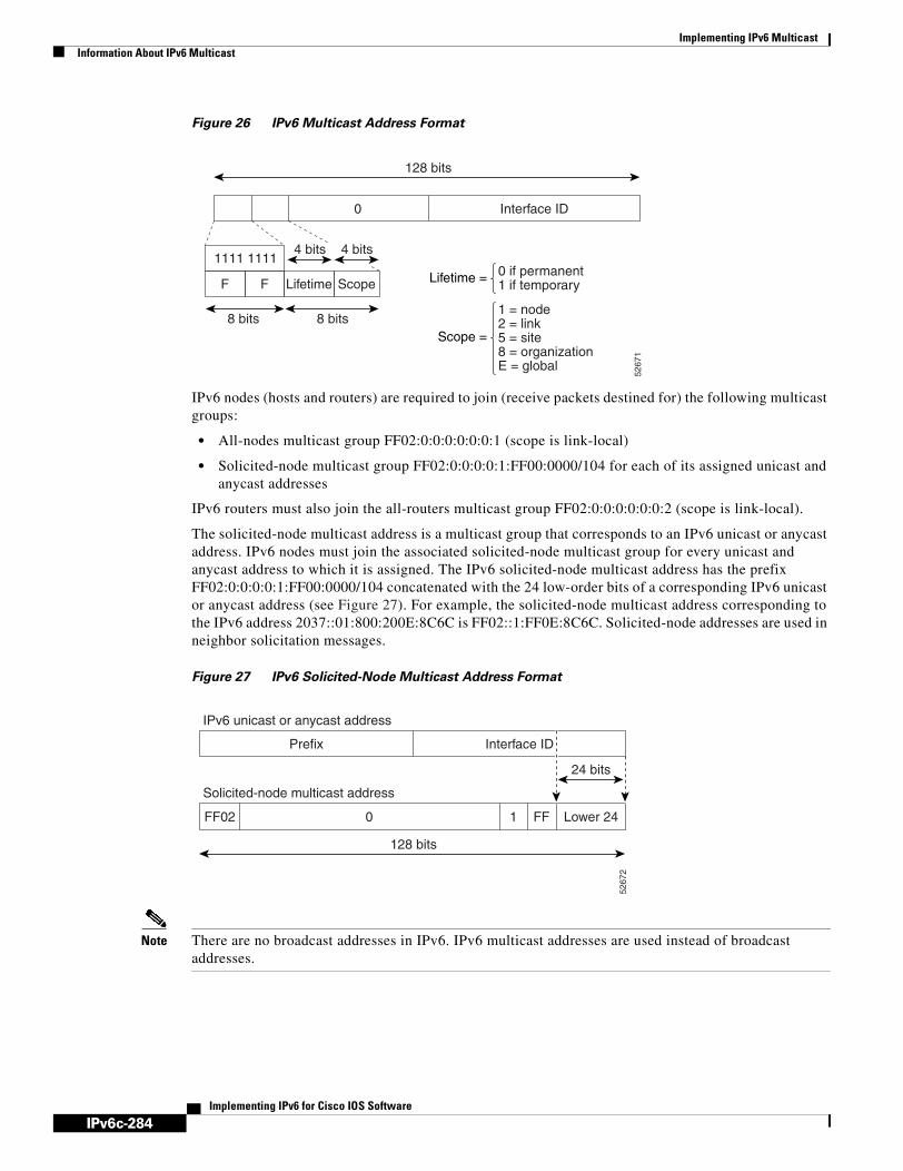
IPv6c-284
Implementing IPv6 MulticastInformation About IPv6 Multicast
Implementing IPv6 for Cisco IOS Software
Figure 26 IPv6 Multicast Address Format
IPv6 nodes (hosts and routers) are required to join (receive packets destined for) the following multicast groups:
• All-nodes multicast group FF02:0:0:0:0:0:0:1 (scope is link-local)
• Solicited-node multicast group FF02:0:0:0:0:1:FF00:0000/104 for each of its assigned unicast and anycast addresses
IPv6 routers must also join the all-routers multicast group FF02:0:0:0:0:0:0:2 (scope is link-local).
The solicited-node multicast address is a multicast group that corresponds to an IPv6 unicast or anycast address. IPv6 nodes must join the associated solicited-node multicast group for every unicast and anycast address to which it is assigned. The IPv6 solicited-node multicast address has the prefix FF02:0:0:0:0:1:FF00:0000/104 concatenated with the 24 low-order bits of a corresponding IPv6 unicast or anycast address (see Figure 27). For example, the solicited-node multicast address corresponding to the IPv6 address 2037::01:800:200E:8C6C is FF02::1:FF0E:8C6C. Solicited-node addresses are used in neighbor solicitation messages.
Figure 27 IPv6 Solicited-Node Multicast Address Format
Note There are no broadcast addresses in IPv6. IPv6 multicast addresses are used instead of broadcast addresses.
5267
1
128 bits
4 bits4 bits
0 if permanent1 if temporary
Interface ID0
1111 1111
8 bits 8 bits
F F Lifetime Scope Lifetime =
1 = node2 = link5 = site8 = organizationE = global
Scope =
5267
2
128 bits
Interface ID
IPv6 unicast or anycast address
Solicited-node multicast address
Prefix
Lower 24
24 bits
FF02 0 1 FF

IPv6c-285
Implementing IPv6 MulticastInformation About IPv6 Multicast
Implementing IPv6 for Cisco IOS Software
IPv6 Multicast Groups
An IPv6 address must be configured on an interface for the interface to forward IPv6 traffic. Configuring a site-local or global IPv6 address on an interface automatically configures a link-local address and activates IPv6 for that interface. Additionally, the configured interface automatically joins the following required multicast groups for that link:
• Solicited-node multicast group FF02:0:0:0:0:1:FF00::/104 for each unicast and anycast address assigned to the interface
• All-nodes link-local multicast group FF02::1
• All-routers link-local multicast group FF02::2
Note The solicited-node multicast address is used in the neighbor discovery process.
For further information on configuring IPv6 addresses, refer to the Implementing Basic Connectivity for IPv6 process module.
Scoped Address Architecture
IPv6 includes support for global and nonglobal addresses. This section describes the usage of IPv6 addresses of different scopes.
A scope zone, or a simply a zone, is a connected region of topology of a given scope. For example, the set of links connected by routers within a particular site, and the interfaces attached to those links, comprise a single zone of site-local scope.
A zone is a particular instance of a topological region (for example, Zone1’s site or Zone2’s site), whereas a scope is the size of a topological region (for example, a site or a link). The zone to which a particular nonglobal address pertains is not encoded in the address itself, but rather is determined by context, such as the interface from which it is sent or received. Therefore, addresses of a given nonglobal scope may be reused in different zones of that scope. For example, Zone1’s site and Zone2’s site may each contain a node with site-local address FEC0::1.
Zones of the different scopes are instantiated as follows:
• Each link, and the interfaces attached to that link, comprises a single zone of link-local scope (for both unicast and multicast).
• There is a single zone of global scope (for both unicast and multicast), comprising all the links and interfaces in the Internet.
• The boundaries of zones of scope other than interface-local, link-local, and global must be defined and configured by network administrators. A site boundary serves as such for both unicast and multicast.
Zone boundaries are relatively static features and do not change in response to short-term changes in topology. Therefore, the requirement that the topology within a zone be “connected” is intended to include links and interfaces that may be connected only occasionally. For example, a residential node or network that obtains Internet access by dialup to an employer’s site may be treated as part of the employer’s site-local zone even when the dialup link is disconnected. Similarly, a failure of a router, interface, or link that causes a zone to become partitioned does not split that zone into multiple zones; rather, the different partitions are still considered to belong to the same zone.
Zones have the following additional properties:
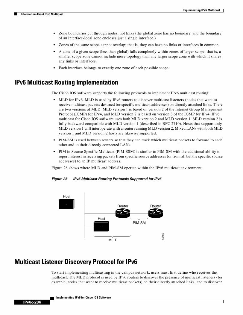
IPv6c-286
Implementing IPv6 MulticastInformation About IPv6 Multicast
Implementing IPv6 for Cisco IOS Software
• Zone boundaries cut through nodes, not links (the global zone has no boundary, and the boundary of an interface-local zone encloses just a single interface.)
• Zones of the same scope cannot overlap; that is, they can have no links or interfaces in common.
• A zone of a given scope (less than global) falls completely within zones of larger scope; that is, a smaller scope zone cannot include more topology than any larger scope zone with which it shares any links or interfaces.
• Each interface belongs to exactly one zone of each possible scope.
IPv6 Multicast Routing ImplementationThe Cisco IOS software supports the following protocols to implement IPv6 multicast routing:
• MLD for IPv6. MLD is used by IPv6 routers to discover multicast listeners (nodes that want to receive multicast packets destined for specific multicast addresses) on directly attached links. There are two versions of MLD: MLD version 1 is based on version 2 of the Internet Group Management Protocol (IGMP) for IPv4, and MLD version 2 is based on version 3 of the IGMP for IPv4. IPv6 multicast for Cisco IOS software uses both MLD version 2 and MLD version 1. MLD version 2 is fully backward-compatible with MLD version 1 (described in RFC 2710). Hosts that support only MLD version 1 will interoperate with a router running MLD version 2. Mixed LANs with both MLD version 1 and MLD version 2 hosts are likewise supported.
• PIM-SM is used between routers so that they can track which multicast packets to forward to each other and to their directly connected LANs.
• PIM in Source Specific Multicast (PIM-SSM) is similar to PIM-SM with the additional ability to report interest in receiving packets from specific source addresses (or from all but the specific source addresses) to an IP multicast address.
Figure 28 shows where MLD and PIM-SM operate within the IPv6 multicast environment.
Figure 28 IPv6 Multicast Routing Protocols Supported for IPv6
Multicast Listener Discovery Protocol for IPv6To start implementing multicasting in the campus network, users must first define who receives the multicast. The MLD protocol is used by IPv6 routers to discover the presence of multicast listeners (for example, nodes that want to receive multicast packets) on their directly attached links, and to discover
PIM-SM
Router Router
Host
Host
MLD 9536
5

IPv6c-287
Implementing IPv6 MulticastInformation About IPv6 Multicast
Implementing IPv6 for Cisco IOS Software
specifically which multicast addresses are of interest to those neighboring nodes. It is used for discovering local group and source-specific group membership. The MLD protocol provides a means to automatically control and limit the flow of multicast traffic throughout your network with the use of special multicast queriers and hosts.
The difference between multicast queriers and hosts is as follows:
• A querier is a network device, such as a router, that sends query messages to discover which network devices are members of a given multicast group.
• A host is a receiver, including routers, that send report messages to inform the querier of a host membership.
A set of queriers and hosts that receive multicast data streams from the same source is called a multicast group. Queriers and hosts use MLD reports to join and leave multicast groups and to begin receiving group traffic.
MLD uses the Internet Control Message Protocol (ICMP) to carry its messages. All MLD messages are link-local with a hop limit of 1, and they all have the router alert option set. The router alert option implies an implementation of the hop-by-hop option header.
MLD has three types of messages:
• Query—General, group-specific, and multicast-address-specific. In a query message, the multicast address field is set to 0 when MLD sends a general query. The general query learns which multicast addresses have listeners on an attached link.
Group-specific and multicast-address-specific queries are the same. A group address is a multicast address.
• Report—In a report message, the multicast address field is that of the specific IPv6 multicast address to which the sender is listening.
• Done—In a done message, the multicast address field is that of the specific IPv6 multicast address to which the source of the MLD message is no longer listening.
An MLD report must be sent with a valid IPv6 link-local source address, or the unspecified address (::), if the sending interface has not yet acquired a valid link-local address. Sending reports with the unspecified address is allowed to support the use of IPv6 multicast in the Neighbor Discovery Protocol.
For stateless autoconfiguration, a node is required to join several IPv6 multicast groups in order to perform duplicate address detection (DAD). Prior to DAD, the only address the reporting node has for the sending interface is a tentative one, which cannot be used for communication. Therefore, the unspecified address must be used.
MLD states that result from MLD version 2 or MLD version 1 membership reports can be limited globally or by interface. The MLD group limits feature provides protection against denial of service (DoS) attacks caused by MLD packets. Membership reports in excess of the configured limits will not be entered in the MLD cache, and traffic for those excess membership reports will not be forwarded.
MLD provides support for source filtering. Source filtering allows a node to report interest in listening to packets only from specific source addresses (as required to support SSM), or from all addresses except specific source addresses sent to a particular multicast address.
When a host using MLD version 1 sends a leave message, the router needs to send query messages to reconfirm that this host was the last MLD version 1 host joined to the group before it can stop forwarding traffic. This function takes about 2 seconds. This so-called “leave latency” is also present in IGMP version 2 for IPv4 multicast.

IPv6c-288
Implementing IPv6 MulticastInformation About IPv6 Multicast
Implementing IPv6 for Cisco IOS Software
MLD Access Group
The MLD access group provides receiver access control in Cisco IOS IPv6 multicast routers. This feature limits the list of groups a receiver can join, and it allows or denies sources used to join SSM channels.
Explicit Tracking of Receivers
The explicit tracking feature allows a router to track the behavior of the hosts within its IPv6 network. This feature also enables the fast leave mechanism to be used with MLD version 2 host reports.
Multicast User Authentication and Profile Support
IPv6 multicast by design allows any host in the network to become a receiver or a source for a multicast group. Therefore, multicast access control is needed to control multicast traffic in the network. Access control functionality consists mainly of source access control and accounting, receiver access control and accounting, and provisioning of this access control mechanism.
Multicast access control provides an interface between multicast and authentication, authorization, and accounting (AAA) for provisioning, authorizing, and accounting at the last-hop router, receiver access control functions in multicast, and group or channel disabling capability in multicast.
When you deploy a new multicast service environment, it is necessary to add user authentication and provide a user profile download on a per-interface basis. The use of AAA and IPv6 multicast supports user authentication and downloading of the user profile in a multicast environment.
The event that triggers the download of a multicast cast access-control profile from the RADIUS server to the access router is arrival of an MLD join on the access router. When this event occurs, a user can case the authorization cache to time out and request download periodically or use an appropriate multicast clear command to trigger a new download in case of profile changes.
Accounting occurs via RADIUS accounting. Start and stop accounting records are sent to the RADIUS server from the access router. In order for you to track resource consumption on a per-stream basis, these accounting records provide information about the multicast source and group. The start record is sent when the last-hop router receives a new MLD report, and the stop record is sent upon MLD leave or if the group or channel is deleted for any reason.
Protocol Independent MulticastProtocol Independent Multicast (PIM) is used between routers so that they can track which multicast packets to forward to each other and to their directly connected LANs. PIM works independently of the unicast routing protocol to perform send or receive multicast route updates like other protocols. Regardless of which unicast routing protocols are being used in the LAN to populate the unicast routing table, Cisco IOS PIM uses the existing unicast table content to perform the Reverse Path Forwarding (RPF) check instead of building and maintaining its own separate routing table.
You can configure IPv6 multicast to use either PIM-SM or PIM-SSM operation, or you can use both PIM-SM and PIM-SSM together in your network.

IPv6c-289
Implementing IPv6 MulticastInformation About IPv6 Multicast
Implementing IPv6 for Cisco IOS Software
PIM-Sparse Mode
IPv6 multicast provides support for intradomain multicast routing using PIM-SM. PIM-SM uses unicast routing to provide reverse-path information for multicast tree building, but it is not dependent on any particular unicast routing protocol.
PIM-SM is used in a multicast network when relatively few routers are involved in each multicast and these routers do not forward multicast packets for a group, unless there is an explicit request for the traffic. PIM-SM distributes information about active sources by forwarding data packets on the shared tree. PIM-SM initially uses shared trees, which requires the use of an RP.
Requests are accomplished via PIM joins, which are sent hop by hop toward the root node of the tree. The root node of a tree in PIM-SM is the RP in the case of a shared tree or the first-hop router that is directly connected to the multicast source in the case of a shortest path tree (SPT). The RP keeps track of multicast groups and the hosts that send multicast packets are registered with the RP by that host’s first-hop router.
As a PIM join travels up the tree, routers along the path set up multicast forwarding state so that the requested multicast traffic will be forwarded back down the tree. When multicast traffic is no longer needed, a router sends a PIM prune up the tree toward the root node to prune (or remove) the unnecessary traffic. As this PIM prune travels hop by hop up the tree, each router updates its forwarding state appropriately. Ultimately, the forwarding state associated with a multicast group or source is removed.
A multicast data sender sends data destined for a multicast group. The designated router (DR) of the sender takes those data packets, unicast-encapsulates them, and sends them directly to the RP. The RP receives these encapsulated data packets, de-encapsulates them, and forwards them onto the shared tree. The packets then follow the (*, G) multicast tree state in the routers on the RP tree, being replicated wherever the RP tree branches, and eventually reaching all the receivers for that multicast group. The process of encapsulating data packets to the RP is called registering, and the encapsulation packets are called PIM register packets.
Designated Router
Cisco routers use PIM-SM to forward multicast traffic and follow an election process to select a designated router when there is more than one router on a LAN segment.
The designated router is responsible for sending PIM register and PIM join and prune messages toward the RP to inform it about host group membership.
If there are multiple PIM-SM routers on a LAN, a designated router must be elected to avoid duplicating multicast traffic for connected hosts. The PIM router with the highest IPv6 address becomes the DR for the LAN unless you choose to force the DR election by use of the ipv6 pim dr-priority command. This command allows you to specify the DR priority of each router on the LAN segment (default priority = 1) so that the router with the highest priority will be elected as the DR. If all routers on the LAN segment have the same priority, then the highest IPv6 address is again used as the tiebreaker.
Figure 29 illustrates what happens on a multiaccess segment. Router A and Router B are connected to a common multiaccess Ethernet segment with Host A as an active receiver for Group A. Only Router A, operating as the DR, sends joins to the RP to construct the shared tree for Group A. If Router B was also permitted to send (*, G) joins to the RP, parallel paths would be created and Host A would receive duplicate multicast traffic. Once Host A begins to source multicast traffic to the group, the DR’s responsibility is to send register messages to the RP. If both routers were assigned the responsibility, the RP would receive duplicate multicast packets.

IPv6c-290
Implementing IPv6 MulticastInformation About IPv6 Multicast
Implementing IPv6 for Cisco IOS Software
Figure 29 Designated Router Election on a Multiaccess Segment
If the DR should fail, the PIM-SM provides a way to detect the failure of Router A and elect a failover DR. If the DR (Router A) became inoperable, Router B would detect this situation when its neighbor adjacency with Router A timed out. Because Router B has been hearing MLD membership reports from Host A, it already has MLD state for Group A on this interface and would immediately send a join to the RP when it became the new DR. This step reestablishes traffic flow down a new branch of the shared tree via Router B. Additionally, if Host A were sourcing traffic, Router B would initiate a new register process immediately after receiving the next multicast packet from Host A. This action would trigger the RP to join the SPT to Host A via a new branch through Router B.
Tips Two PIM routers are neighbors if there is a direct connection between them. To display your PIM neighbors, use the show ipv6 pim neighbor command in privileged EXEC mode.
Note DR election process is required only on multiaccess LANs. The last-hop router directly connected to the host is the DR.
Rendezvous Point
IPv6 PIM provides embedded RP support. Embedded RP support allows the router to learn RP information using the multicast group destination address instead of the statically configured RP. For routers that are the RP, the router must be statically configured as the RP.
The router searches for embedded RP group addresses in MLD reports or PIM messages and data packets. On finding such an address, the router learns the RP for the group from the address itself. It then uses this learned RP for all protocol activity for the group. For routers that are the RP, the router is advertised as an embedded RP must be configured as the RP.
To select a static RP over an embedded RP, the specific embedded RP group range or mask must be configured in the access list of the static RP. When PIM is configured in sparse mode, you must also choose one or more routers to operate as an RP. An RP is a single common root placed at a chosen point of a shared distribution tree and is configured statically in each box.
RP
HostMember ofGroup A
(*,G) Join
Router A(DR)
Router B
9536
6

IPv6c-291
Implementing IPv6 MulticastInformation About IPv6 Multicast
Implementing IPv6 for Cisco IOS Software
PIM DRs forward data from directly connected multicast sources to the RP for distribution down the shared tree. Data is forwarded to the RP in one of two ways:
• Data is encapsulated in register packets and unicast directly to the RP by the first-hop router operating as the DR.
• If the RP has itself joined the source tree, it is multicast-forwarded per the RPF forwarding algorithm described in the “PIM-Sparse Mode” section.
The RP address is used by first-hop routers to send PIM register messages on behalf of a host sending a packet to the group. The RP address is also used by last-hop routers to send PIM join and prune messages to the RP to inform it about group membership. You must configure the RP address on all routers (including the RP router).
A PIM router can be an RP for more than one group. Only one RP address can be used at a time within a PIM domain for a certain group. The conditions specified by the access list determine for which groups the router is an RP.
IPv6 multicast supports the PIM accept register feature, which is the ability to perform PIM-SM register message filtering at the RP. The user can match an access list or compare the AS path for the registered source with the AS path specified in a route map.
IPv6 BSR
PIM routers in a domain must be able to map each multicast group to the correct RP address. The BSR protocol for PIM-SM provides a dynamic, adaptive mechanism to distribute group-to-RP mapping information rapidly throughout a domain. With the IPv6 BSR feature, if an RP becomes unreachable, it will be detected and the mapping tables will be modified so that the unreachable RP is no longer used, and the new tables will be rapidly distributed throughout the domain.
Every PIM-SM multicast group needs to be associated with the IP or IPv6 address of an RP. When a new multicast sender starts sending, its local DR will encapsulate these data packets in a PIM register message and send them to the RP for that multicast group. When a new multicast receiver joins, its local DR will send a PIM join message to the RP for that multicast group. When any PIM router sends a (*, G) join message, the PIM router needs to know which is the next router toward the RP so that G (Group) can send a message to that router. Also, when a PIM router is forwarding data packets using (*, G) state, the PIM router needs to know which is the correct incoming interface for packets destined for G, because it needs to reject any packets that arrive on other interfaces.
A small set of routers from a domain are configured as candidate bootstrap routers (C-BSRs) and a single BSR is selected for that domain. A set of routers within a domain are also configured as candidate RPs (C-RPs); typically, these routers are the same routers that are configured as C-BSRs. Candidate RPs periodically unicast candidate-RP-advertisement (C-RP-Adv) messages to the BSR of that domain, advertising their willingness to be an RP. A C-RP-Adv message includes the address of the advertising C-RP, and an optional list of group addresses and mask length fields, indicating the group prefixes for which the candidacy is advertised. The BSR then includes a set of these C-RPs, along with their corresponding group prefixes, in bootstrap messages (BSMs) it periodically originates. BSMs are distributed hop-by-hop throughout the domain.
The IPv6 BSR ability to configure RP mapping allows IPv6 multicast routers to be statically configured to announce scope-to-RP mappings directly from the BSR instead of learning them from candidate-RP messages. Announcing RP mappings from the BSR is useful in several situations:
• When an RP address never changes because there is only a single RP or the group range uses an anycast RP, it may be less complex to configure the RP address announcement statically on the candidate BSRs.
IPv6c-292
Implementing IPv6 MulticastInformation About IPv6 Multicast
Implementing IPv6 for Cisco IOS Software
• When an RP address is a virtual RP address (such as when using bidirectional PIM), it cannot be learned by the BSR from a candidate-RP. Instead, the virtual RP address must be configured as an announced RP on the candidate BSRs.
Cisco IOS IPv6 routers provide support for the RPF flooding of BSR packets so that a Cisco IOS IPv6 router will not disrupt the flow of BSMs. The router will recognize and parse enough of the BSM to identify the BSR address. The router performs an RPF check for this BSR address and forwards the packet only if it is received on the RPF interface. The router also creates a BSR entry containing RPF information to use for future BSMs from the same BSR. When BSMs from a given BSR are no longer received, the BSR entry is timed out.
Bidirectional BSR support allows bidirectional RPs to be advertised in C-RP messages and bidirectional ranges in the BSM. All routers in a system must be able to use the bidirectional range in the BSM; otherwise, the bidirectional RP feature will not function.
BSR provides scoped zone support by distributing group-to-RP mappings in networks using administratively scoped multicast. The user can configure candidate BSRs and a set of candidate RPs for each administratively scoped region in the user’s domain.
For BSR to function correctly with administrative scoping, a BSR and at least one C-RP must be within every administratively scoped region. Administratively scoped zone boundaries must be configured at the zone border routers (ZBRs), because they need to filter PIM join messages that might inadvertently cross the border due to error conditions. In addition, at least one C-BSR within the administratively scoped zone must be configured to be a C-BSR for the administratively scoped zone’s address range.
A separate BSR election will then take place (using BSMs) for every administratively scoped range, plus one for the global range. Administratively scoped ranges are identified in the BSM because the group range is marked to indicate that this is an administrative scope range, not just a range that a particular set of RPs is configured to handle.
Unless the C-RP is configured with a scope, it discovers the existence of the administratively scoped zone and its group range through reception of a BSM from the scope zone’s elected BSR containing the scope zone’s group range. A C-RP stores each elected BSR's address and the administratively scoped range contained in its BSM. It separately unicasts C-RP-Adv messages to the appropriate BSR for every administratively scoped range within which it is willing to serve as an RP.
All PIM routers within a PIM bootstrap domain where administratively scoped ranges are in use must be able to receive BSMs and store the winning BSR and RP set for all administratively scoped zones that apply.
PIM-Source Specific Multicast
PIM-SSM is the routing protocol that supports the implementation of SSM and is derived from PIM-SM. However, unlike PIM-SM where data from all multicast sources are sent when there is a PIM join, the SSM feature forwards datagram traffic to receivers from only those multicast sources that the receivers have explicitly joined, thus optimizing bandwidth utilization and denying unwanted Internet broadcast traffic. Further, instead of the use of RP and shared trees, SSM uses information found on source addresses for a multicast group. This information is provided by receivers through the source addresses relayed to the last-hop routers by MLD membership reports, resulting in resulting in shortest-path trees directly to the sources.
In SSM, delivery of datagrams is based on (S, G) channels. Traffic for one (S, G) channel consists of datagrams with an IPv6 unicast source address S and the multicast group address G as the IPv6 destination address. Systems will receive this traffic by becoming members of the (S, G) channel. Signaling is not required, but receivers must subscribe or unsubscribe to (S, G) channels to receive or not receive traffic from specific sources.

IPv6c-293
Implementing IPv6 MulticastInformation About IPv6 Multicast
Implementing IPv6 for Cisco IOS Software
MLD version 2 is required for SSM to operate. MLD allows the host to provide source information. Before SSM will run with MLD, SSM must be supported in the Cisco IOS IPv6 router, the host where the application is running, and the application itself.
SSM Mapping for IPv6
SSM mapping for IPv6 supports both static and dynamic Domain Name System (DNS) mapping for MLD version 1 receivers. This feature allows deployment of IPv6 SSM with hosts that are incapable of providing MLD version 2 support in their TCP/IP host stack and their IP multicast receiving application.
SSM mapping allows the router to look up the source of a multicast MLD version 1 report either in the running configuration of the router or from a DNS server. The router can then initiate an (S, G) join toward the source.
PIM Shared Tree and Source Tree (Shortest-Path Tree)
By default, members of a group receive data from senders to the group across a single data distribution tree rooted at the RP. This type of distribution tree is called shared tree or rendezvous point tree (RPT), as illustrated in Figure 30. Data from senders is delivered to the RP for distribution to group members joined to the shared tree.
Figure 30 Shared Tree and Source Tree (Shortest Path Tree)
If the data threshold warrants, leaf routers on the shared tree may initiate a switch to the data distribution tree rooted at the source. This type of distribution tree is called a shortest path tree or source tree. By default, the Cisco IOS software switches to a source tree upon receiving the first data packet from a source.
The following process describes the move from shared tree to source tree in more detail:
1. Receiver joins a group; leaf Router C sends a join message toward the RP.
Router A
Source
Receiver
Router C RP
Router B
Shared treefrom RP
Source tree(shortest
path tree)
5264
7

IPv6c-294
Implementing IPv6 MulticastInformation About IPv6 Multicast
Implementing IPv6 for Cisco IOS Software
2. RP puts the link to Router C in its outgoing interface list.
3. Source sends the data; Router A encapsulates the data in the register and sends it to the RP.
4. RP forwards the data down the shared tree to Router C and sends a join message toward the source. At this point, data may arrive twice at Router C, once encapsulated and once natively.
5. When data arrives natively (unencapsulated) at the RP, the RP sends a register-stop message to Router A.
6. By default, receipt of the first data packet prompts Router C to send a join message toward the source.
7. When Router C receives data on (S, G), it sends a prune message for the source up the shared tree.
8. RP deletes the link to Router C from the outgoing interface of (S, G).
9. RP triggers a prune message toward the source.
Join and prune messages are sent for sources and RPs. They are sent hop-by-hop and are processed by each PIM router along the path to the source or RP. Register and register-stop messages are not sent hop-by-hop. They are sent by the designated router that is directly connected to a source and are received by the RP for the group.
Reverse Path Forwarding
Reverse-path forwarding is used for forwarding multicast datagrams. It functions as follows:
• If a router receives a datagram on an interface it uses to send unicast packets to the source, the packet has arrived on the RPF interface.
• If the packet arrives on the RPF interface, a router forwards the packet out the interfaces present in the outgoing interface list of a multicast routing table entry.
• If the packet does not arrive on the RPF interface, the packet is silently discarded to prevent loops.
PIM uses both source trees and RP-rooted shared trees to forward datagrams; the RPF check is performed differently for each, as follows:
• If a PIM router has source-tree state (that is, an (S, G) entry is present in the multicast routing table), the router performs the RPF check against the IPv6 address of the source of the multicast packet.
• If a PIM router has shared-tree state (and no explicit source-tree state), it performs the RPF check on the RP’s address (which is known when members join the group).
Sparse-mode PIM uses the RPF lookup function to determine where it needs to send joins and prunes. (S, G) joins (which are source-tree states) are sent toward the source. (*, G) joins (which are shared-tree states) are sent toward the RP.
Routable Address Hello Option
When an IPv6 interior gateway protocol is used to build the unicast routing table, the procedure to detect the upstream router address assumes the address of a PIM neighbor is always same as the address of the next-hop router, as long as they refer to the same router. However, it may not be the case when a router has multiple addresses on a link.
Two typical situations can lead to this situation for IPv6. The first situation can occur when the unicast routing table is not built by an IPv6 interior gateway protocol such as multicast BGP. The second situation occurs when the address of an RP shares a subnet prefix with down stream routers (note that the RP router address has to be domain-wide and therefore cannot be a link-local address).

IPv6c-295
Implementing IPv6 MulticastInformation About IPv6 Multicast
Implementing IPv6 for Cisco IOS Software
The routable address hello option allows the PIM protocol avoid such situations by adding a PIM hello message option that includes all the addresses on the interface on which the PIM hello message is advertised. When a PIM router finds an upstream router for some address, the result of RPF calculation is compared with the addresses in this option, in addition to PIM neighbor’s address itself. Because this option includes all the possible addresses of a PIM router on that link, it always includes the RPF calculation result if it refers to the PIM router supporting this option.
Bidirectional PIM
Bidirectional PIM allows multicast routers to keep reduced state information, as compared with unidirectional shared trees in PIM-SM. Bidirectional shared trees convey data from sources to the RP and distribute them from the RP to the receivers. Unlike PIM-SM, bidirectional PIM does not switch over to the source tree, and there is no register encapsulation of data from the source to the RP.
Bidirectional PIM offers advantages when there are many moderate or low-rate sources. However, the bidirectional source trees have worse delay characteristics than do the source trees built in PIM-SM.
Only static configuration of bidirectional RPs is supported in IPv6.
Static MroutesIPv6 static mroutes behave much in the same way as do IPv6 static routes. IPv6 static mroutes share the same database as IPv6 static routes and are implemented by extending static route support. Static mroutes support equal-cost multipath mroutes, and they also support unicast-only static routes.
For further information on IPv6 static routes, see the Implementing Static Routes for IPv6 module.
MRIBThe Multicast Routing Information Base (MRIB) is a protocol-independent repository of multicast routing entries instantiated by multicast routing protocols (routing clients). Its main function is to provide independence between routing protocols and the Multicast Forwarding Information Base (MFIB). It also acts as a coordination and communication point among its clients.
Routing clients use the services provided by the MRIB to instantiate routing entries and retrieve changes made to routing entries by other clients. Besides routing clients, MRIB also has forwarding clients (MFIB instances) and special clients such as MLD. MFIB retrieves its forwarding entries from MRIB and notifies the MRIB of any events related to packet reception. These notifications can either be explicitly requested by routing clients or spontaneously generated by the MFIB.
Another important function of the MRIB is to allow for the coordination of multiple routing clients in establishing multicast connectivity within the same multicast session. MRIB also allows for the coordination between MLD and routing protocols.
MFIBThe MFIB is a platform-independent and routing-protocol-independent library for IPv6 software. Its main purpose is to provide a Cisco IOS platform with an interface with which to read the IPv6 multicast forwarding table and notifications when the forwarding table changes. The information provided by the MFIB has clearly defined forwarding semantics and is designed to make it easy for the platform to translate to its specific hardware or software forwarding mechanisms.

IPv6c-296
Implementing IPv6 MulticastInformation About IPv6 Multicast
Implementing IPv6 for Cisco IOS Software
When routing or topology changes occur in the network, the IPv6 routing table is updated, and those changes are reflected in the MFIB. The MFIB maintains next-hop address information based on the information in the IPv6 routing table. Because there is a one-to-one correlation between MFIB entries and routing table entries, the MFIB contains all known routes and eliminates the need for route cache maintenance that is associated with switching paths such as fast switching and optimum switching.
Distributed MFIB
Distributed MFIB (dMFIB) is used to switch multicast IPv6 packets on distributed platforms. dMFIB may also contain platform-specific information on replication across line cards. The basic MFIB routines that implement the core of the forwarding logic are common to all forwarding environments.
dMFIB implements the following functionalities:
• Distributes a copy of the MFIB to the line cards.
• Relays data-driven protocol events generated in the line cards to PIM.
• Provides an MFIB platform application program interface (API) to propagate MFIB changes to platform-specific code responsible for programming the hardware acceleration engine. This API also includes entry points to switch a packet in software (necessary if the packet is triggering a data-driven event) and to upload traffic statistics to the software.
• Provides hooks to allow clients residing on the RP to read traffic statistics on demand. (dMFIB does not periodically upload these statistics to the RP.)
The combination of dMFIB and MRIB subsystems also allows the router to have a “customized” copy of the MFIB database in each line card and to transport MFIB-related platform-specific information from the RP to the line cards.
IPv6 Multicast Process Switching and Fast SwitchingA unified MFIB is used to provide both fast switching and process switching support for PIM-SM and PIM-SSM in IPv6 multicast. In process switching, the Route Processor must examine, rewrite, and forward each packet. The packet is first received and copied into the system memory. The router then looks up the Layer 3 network address in the routing table. The Layer 2 frame is then rewritten with the next-hop destination address and sent to the outgoing interface. The RP also computes the cyclic redundancy check (CRC). This switching method is the least scalable method for switching IPv6 packets.
IPv6 multicast fast switching allows routers to provide better packet forwarding performance than process switching. Information conventionally stored in a route cache is stored in several data structures for IPv6 multicast switching. The data structures provide optimized lookup for efficient packet forwarding.
In IPv6 multicast forwarding, the first packet is fast-switched if the PIM protocol logic allows it. Also in IPv6 multicast fast switching, the MAC encapsulation header is precomputed. IPv6 multicast fast switching uses the MFIB to make IPv6 destination prefix-based switching decisions. In addition to the MFIB, IPv6 multicast fast switching uses adjacency tables to prepend Layer 2 addressing information. The adjacency table maintains Layer 2 next-hop addresses for all MFIB entries.
The adjacency table is populated as adjacencies are discovered. Each time an adjacency entry is created (such as through the ARP protocol), a link-layer header for that adjacent node is precomputed and stored in the adjacency table. Once a route is determined, it points to a next hop and corresponding adjacency entry. It is subsequently used for encapsulation during switching of packets.

IPv6c-297
Implementing IPv6 MulticastHow to Implement IPv6 Multicast
Implementing IPv6 for Cisco IOS Software
A route might have several paths to a destination prefix, such as when a router is configured for simultaneous load balancing and redundancy. For each resolved path, a pointer is added for the adjacency corresponding to the next-hop interface for that path. This mechanism is used for load balancing across several paths.
Multiprotocol BGP for the IPv6 Multicast Address FamilyThe multicast BGP for the IPv6 multicast address family feature provides multicast BGP extensions for IPv6 and supports the same features and functionality as IPv4 BGP. IPv6 enhancements to multicast BGP include support for an IPv6 multicast address family and network layer reachability information (NLRI) and next hop (the next router in the path to the destination) attributes that use IPv6 addresses.
Multicast BGP is an enhanced BGP that allows the deployment of interdomain IPv6 multicast. Multicast BGP carries routing information for multiple network layer protocol address families; for example, IPv6 address family and for IPv6 multicast routes. The IPv6 multicast address family contains routes used for RPF lookup by the IPv6 PIM protocol, and multicast BGP IPv6 provides for interdomain transport of the same. Users must use multicast BGP for IPv6 multicast when using IPv6 multicast with BGP because the unicast multicast BGP learned routes will not be used for IPv6 multicast.
Multicast BGP functionality provided through a separate address family context. A subsequent address family identifier (SAFI) provides information about the type of the network layer reachability information that is carried in the attribute. Multicast BGP unicast uses SAFI 1 messages, and multiprotocol BGP multicast uses SAFI 2 messages.
A separate BGP routing table is maintained to configure incongruent policies and topologies (for example, IPv6 unicast and multicast) by using IPv6 multicast RPF lookup. Multicast RPF lookup is very similar to the IP unicast route lookup.
No MRIB is associated with the IPv6 multicast BGP table. However, IPv6 multicast BGP operates on the unicast IPv6 RIB when needed. Multicast BGP does not insert or update routes into the IPv6 unicast RIB.
How to Implement IPv6 MulticastThe tasks in the following sections explain how to implement IPv6 multicast:
• Enabling IPv6 Multicast Routing, page 298
• Configuring the MLD Protocol, page 298
• Configuring PIM, page 308
• Configuring a BSR, page 315
• Configuring SSM Mapping, page 319
• Configuring Static Mroutes, page 320
• Configuring IPv6 Multiprotocol BGP, page 322
• Using MFIB in IPv6 Multicast, page 332
• Disabling Default Features in IPv6 Multicast, page 334
• Troubleshooting IPv6 Multicast, page 339

IPv6c-298
Implementing IPv6 MulticastHow to Implement IPv6 Multicast
Implementing IPv6 for Cisco IOS Software
Enabling IPv6 Multicast RoutingThis task explains how to enable IPv6 multicast routing on all interfaces and to enable multicast forwarding for PIM and MLD on all enabled interfaces of the router.
Prerequisites
In order to enable IPv6 multicast routing on a router, you must first enable IPv6 unicast routing on the router. For information on how to enable IPv6 unicast routing on a router, refer to Implementing Basic Connectivity for IPv6.
If you are already using an IPv6 unicast router, use the following tasks to enable IPv6 multicast routing and configure IPv6 multicast routing options.
SUMMARY STEPS
1. enable
2. configure terminal
3. ipv6 multicast-routing
DETAILED STEPS
Configuring the MLD ProtocolThe following tasks describe how to customize and verify the MLD protocol.
• Customizing and Verifying MLD on an Interface, page 299
• Implementing MLD Group Limits, page 301
• Configuring Explicit Tracking of Receivers to Track Host Behavior, page 303
• Configuring Multicast User Authentication and Profile Support, page 304
• Resetting the MLD Traffic Counters, page 307
• Clearing the MLD Interface Counters, page 308
Command or Action Purpose
Step 1 enable
Example:Router> enable
Enables privileged EXEC mode.
• Enter your password if prompted.
Step 2 configure terminal
Example:Router# configure terminal
Enters global configuration mode.
Step 3 ipv6 multicast-routing
Example:Router(config)# ipv6 multicast-routing
Enables multicast routing on all IPv6-enabled interfaces and enables multicast forwarding for PIM and MLD on all enabled interfaces of the router.

IPv6c-299
Implementing IPv6 MulticastHow to Implement IPv6 Multicast
Implementing IPv6 for Cisco IOS Software
Customizing and Verifying MLD on an Interface
Use the following tasks to customize MLD and verify MLD information on each interface, if desired.
SUMMARY STEPS
1. enable
2. configure terminal
3. interface type number
4. ipv6 mld join-group [group-name | group-address] [[include | exclude] source-address | source-name]
5. ipv6 mld access-group access-list-name
6. ipv6 mld static-group [group-name | group-address] [[include | exclude] source-address | source-name]
7. ipv6 mld query-max-response-time seconds
8. ipv6 mld query-timeout seconds
9. ipv6 mld query-interval seconds
10. exit
11. show ipv6 mld groups [link-local] [group-name | group-address] [interface-type interface-number] [detail | explicit]
12. show ipv6 mld groups summary
13. show ipv6 mld interface [type number]
DETAILED STEPS
Command or Action Purpose
Step 1 enable
Example:Router> enable
Enables privileged EXEC mode.
• Enter your password if prompted.
Step 2 configure terminal
Example:Router# configure terminal
Enters global configuration mode.
Step 3 interface type number
Example:Router(config)# interface FastEthernet 1/0
Specifies an interface type and number, and places the router in interface configuration mode.

IPv6c-300
Implementing IPv6 MulticastHow to Implement IPv6 Multicast
Implementing IPv6 for Cisco IOS Software
Step 4 ipv6 mld join-group [group-name | group-address] [[include | exclude] source-address | source-name]
Example:Router(config-if)# ipv6 mld join-group FF04::12 exclude 2001:0DB8::10::11
Configures MLD reporting for a specified group and source.
Step 5 ipv6 mld access-group access-list-name
Example:Router(config-if)# ipv6 access-list acc-grp-1
Allows the user to perform IPv6 multicast receiver access control.
Step 6 ipv6 mld static-group [group-name | group-address] [[include | exclude] source-address | source-name]
Example:Router(config-if)# ipv6 mld static-group ff04::10 include 100::1
Statically forwards traffic for the multicast group onto a specified interface and cause the interface to behave as if a MLD joiner were present on the interface.
Step 7 ipv6 mld query-max-response-time seconds
Example:Router(config-if)# ipv6 mld query-max-response-time 20
Configures the maximum response time advertised in MLD queries.
Step 8 ipv6 mld query-timeout seconds
Example:Router(config-if)# ipv6 mld query-timeout 130
Configures the timeout value before the router takes over as the querier for the interface.
Step 9 ipv6 mld query-interval seconds
Example:Router(config-if)# ipv6 mld query-interval 60
Configures the frequency at which the Cisco IOS software sends MLD host-query messages.
Caution Changing this value may severely impact multicast forwarding.
Step 10 exit
Example:Router(config-if)# exit
Enter this command twice to exit interface configuration mode and enter privileged EXEC mode.
Step 11 show ipv6 mld groups [link-local] [group-name | group-address] [interface-type interface-number] [detail | explicit]
Example:Router# show ipv6 mld groups FastEthernet 2/1
Displays the multicast groups that are directly connected to the router and that were learned through MLD.
Command or Action Purpose

IPv6c-301
Implementing IPv6 MulticastHow to Implement IPv6 Multicast
Implementing IPv6 for Cisco IOS Software
Implementing MLD Group Limits
Per-interface and global MLD limits operate independently of each other. Both per-interface and global MLD limits can be configured on the same router. The number of MLD limits, globally or per interface, is not configured by default; the limits must be configured by the user. A membership report that exceeds either the per-interface or the global state limit is ignored.
The following tasks describe how to limit MLD states that result from MLD version 2 or MLD version 1 membership reports globally or per interface:
• Implementing MLD Group Limits Globally, page 301
• Clearing the MLD Interface Counters, page 308
Implementing MLD Group Limits Globally
This task describes how to limit MLD groups globally.
SUMMARY STEPS
1. enable
2. configure terminal
3. ipv6 mld state-limit number
Step 12 show ipv6 mld groups summary
Example:Router# show ipv6 mld groups summary
Displays the number of (*, G) and (S, G) membership reports present in the MLD cache.
Step 13 show ipv6 mld interface [type number]
Example:Router# show ipv6 mld interface FastEthernet 2/1
Displays multicast-related information about an interface.
Command or Action Purpose

IPv6c-302
Implementing IPv6 MulticastHow to Implement IPv6 Multicast
Implementing IPv6 for Cisco IOS Software
DETAILED STEPS
Implementing MLD Group Limits per Interface
This task describes how to limit MLD groups on a per-interface basis.
SUMMARY STEPS
1. enable
2. configure terminal
3. interface type number
4. ipv6 mld limit number [except access-list]
DETAILED STEPS
Command or Action Purpose
Step 1 enable
Example:Router> enable
Enables privileged EXEC mode.
• Enter your password if prompted.
Step 2 configure terminal
Example:Router# configure terminal
Enters global configuration mode.
Step 3 ipv6 mld state-limit number
Example:Router(config)# ipv6 mld state-limit 300
Limits the number of MLD states globally.
Command or Action Purpose
Step 1 enable
Example:Router> enable
Enables privileged EXEC mode.
• Enter your password if prompted.
Step 2 configure terminal
Example:Router# configure terminal
Enters global configuration mode.

IPv6c-303
Implementing IPv6 MulticastHow to Implement IPv6 Multicast
Implementing IPv6 for Cisco IOS Software
Configuring Explicit Tracking of Receivers to Track Host Behavior
This task enables the explicit tracking of receivers feature. The explicit tracking feature allows a router to track the behavior of the hosts within its IPv6 network and enables the fast leave mechanism to be used with MLD version 2 host reports.
SUMMARY STEPS
1. enable
2. configure terminal
3. interface type number
4. ipv6 mld explicit-tracking access-list-name
DETAILED STEPS
Step 3 interface type number
Example:Router(config)# interface FastEthernet 1/0
Specifies an interface type and number, and places the router in interface configuration mode.
Step 4 ipv6 mld limit number [except access-list]
Example:Router(config-if)# ipv6 mld limit 100
Limits the number of MLD states on a per-interface basis.
Command or Action Purpose
Command or Action Purpose
Step 1 enable
Example:Router> enable
Enables privileged EXEC mode.
• Enter your password if prompted.
Step 2 configure terminal
Example:Router# configure terminal
Enters global configuration mode.
Step 3 interface type number
Example:Router(config)# interface FastEthernet 1/0
Specifies an interface type and number, and places the router in interface configuration mode.
Step 4 ipv6 mld explicit-tracking access-list-name
Example:Router(config-if)# ipv6 mld explicit-tracking
list1
Enables explicit tracking of hosts.

IPv6c-304
Implementing IPv6 MulticastHow to Implement IPv6 Multicast
Implementing IPv6 for Cisco IOS Software
Configuring Multicast User Authentication and Profile Support
This section describes several tasks used to enable and configure the multicast user authentication and profile support feature.
Prerequisites
Before you configure multicast user authentication and profile support, you may configure the following receiver access control functions in IPv6 multicast.
• To limit MLD groups globally, see the “Implementing MLD Group Limits Globally” section on page 301.
• To limit MLD groups on a per-interface basis, see the “Implementing MLD Group Limits per Interface” section on page 302
• To specify the MLD groups and sources allowed on an interface, see the “Customizing and Verifying MLD on an Interface” section on page 299, step 5.
Restrictions
• The port, interface, VC, or VLAN ID is the user or subscriber identity. User identity by hostname, user ID or password is not supported.
To configure multicast user authentication and profile support, perform the following tasks:
• Enabling AAA Access Control for IPv6 Multicast, page 304
• Specifying Method Lists and Enabling Multicast Accounting, page 305
• Disabling the Router from Receiving Unauthenticated Multicast Traffic, page 306
• Resetting Authorization Status on an MLD Interface, page 307
Enabling AAA Access Control for IPv6 Multicast
The following task describes how to enable AAA access control.
SUMMARY STEPS
1. enable
2. configure terminal
3. aaa new-model

IPv6c-305
Implementing IPv6 MulticastHow to Implement IPv6 Multicast
Implementing IPv6 for Cisco IOS Software
DETAILED STEPS
Specifying Method Lists and Enabling Multicast Accounting
The following task describes how to specify the method lists used for AAA authorization and accounting and how to enable multicast accounting on specified groups or channels on an interface.
SUMMARY STEPS
1. enable
2. configure terminal
3. aaa authorization multicast default [method3 | method4]
4. aaa accounting multicast default [start-stop | stop-only] [broadcast] [method1] [method2] [method3] [method4]
5. interface type number
6. ipv6 multicast aaa account receive access-list-name [throttle throttle-number]
DETAILED STEPS
Command or Action Purpose
Step 1 enable
Example:Router> enable
Enables privileged EXEC mode.
• Enter your password if prompted.
Step 2 configure terminal
Example:Router# configure terminal
Enters global configuration mode.
Step 3 aaa new-model
Example:Router(config)# aaa new-model
Enables the AAA access control system.
Command or Action Purpose
Step 1 enable
Example:Router> enable
Enables privileged EXEC mode.
• Enter your password if prompted.
Step 2 configure terminal
Example:Router# configure terminal
Enters global configuration mode.

IPv6c-306
Implementing IPv6 MulticastHow to Implement IPv6 Multicast
Implementing IPv6 for Cisco IOS Software
In some situations, access control may be needed to prevent multicast traffic from being received unless the subscriber is authenticated and the channels are authorized as per access control profiles. That is, there should be no traffic at all unless specified otherwise by access control profiles.
Disabling the Router from Receiving Unauthenticated Multicast Traffic
The following task describes how to disable the router from receiving multicast traffic to be received from unauthenticated groups or unauthorized channels.
SUMMARY STEPS
1. enable
2. configure terminal
3. ipv6 multicast disable-group [access-list-name]
Step 3 aaa authorization multicast default [method3 | method4]
Example:Router(config)# aaa authorization multicast default
Enables AAA authorization and sets parameters that restrict user access to an IPv6 multicast network.
Step 4 aaa accounting multicast default [start-stop | stop-only] [broadcast] [method1] [method2] [method3] [method4]
Example:Router(config)# aaa accounting multicast default
Enables AAA accounting of IPv6 multicast services for billing or security purposes when you use RADIUS.
Step 5 interface type number
Example:Router(config)# interface FastEthernet 1/0
Specifies an interface type and number, and places the router in interface configuration mode.
Step 6 ipv6 multicast aaa account receive access-list-name [throttle throttle-number]
Example:Router(config-if)# ipv6 multicast aaa account receive list1
Enables AAA accounting on specified groups or channels.
Command or Action Purpose
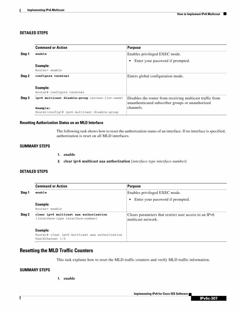
IPv6c-307
Implementing IPv6 MulticastHow to Implement IPv6 Multicast
Implementing IPv6 for Cisco IOS Software
DETAILED STEPS
Resetting Authorization Status on an MLD Interface
The following task shows how to reset the authorization status of an interface. If no interface is specified, authorization is reset on all MLD interfaces.
SUMMARY STEPS
1. enable
2. clear ipv6 multicast aaa authorization [interface-type interface-number]
DETAILED STEPS
Resetting the MLD Traffic Counters
This task explains how to reset the MLD traffic counters and verify MLD traffic information.
SUMMARY STEPS
1. enable
Command or Action Purpose
Step 1 enable
Example:Router> enable
Enables privileged EXEC mode.
• Enter your password if prompted.
Step 2 configure terminal
Example:Router# configure terminal
Enters global configuration mode.
Step 3 ipv6 multicast disable-group [access-list-name]
Example:Router(config)# ipv6 multicast disable-group
Disables the router from receiving multicast traffic from unauthenticated subscriber groups or unauthorized channels.
Command or Action Purpose
Step 1 enable
Example:Router> enable
Enables privileged EXEC mode.
• Enter your password if prompted.
Step 2 clear ipv6 multicast aaa authorization [interface-type interface-number]
Example:Router# clear ipv6 multicast aaa authorization FastEthernet 1/0
Clears parameters that restrict user access to an IPv6 multicast network.

IPv6c-308
Implementing IPv6 MulticastHow to Implement IPv6 Multicast
Implementing IPv6 for Cisco IOS Software
2. clear ipv6 mld traffic
3. show ipv6 mld traffic
DETAILED STEPS
Clearing the MLD Interface Counters
This task explains how to clear MLD interface counters.
SUMMARY STEPS
1. enable
2. clear ipv6 mld counters
DETAILED STEPS
Configuring PIM The following tasks explains how to configure PIM-SM and display PIM-SM configuration and information.
Command or Action Purpose
Step 1 enable
Example:Router> enable
Enables privileged EXEC mode.
• Enter your password if prompted.
Step 2 clear ipv6 mld traffic
Example:Router# clear ipv6 mld traffic
Resets all MLD traffic counters.
Step 3 show ipv6 mld traffic
Example:Router# show ipv6 mld traffic
Displays the MLD traffic counters.
Command or Action Purpose
Step 1 enable
Example:Router> enable
Enables privileged EXEC mode.
• Enter your password if prompted.
Step 2 clear ipv6 mld counters
Example:Router# clear ipv6 mld counters Ethernet1/0
Clears the MLD interface counters.

IPv6c-309
Implementing IPv6 MulticastHow to Implement IPv6 Multicast
Implementing IPv6 for Cisco IOS Software
• Configuring PIM-SM and Displaying PIM-SM Information for a Group Range, page 309
• Configuring PIM Options, page 310
• Configuring Bidirectional PIM and Displaying Bidirectional PIM Information, page 312
• Resetting the PIM Traffic Counters, page 313
• Clearing the PIM Topology Table to Reset the MRIB Connection, page 314
Configuring PIM-SM and Displaying PIM-SM Information for a Group Range
This task explains how to configure PIM-SM and display PIM-SM configuration and information.
SUMMARY STEPS
1. enable
2. configure terminal
3. ipv6 pim rp-address ipv6-address [group-access-list] [bidir]
4. exit
5. show ipv6 pim interface [state-on] [state-off] [type number]
6. show ipv6 pim group-map [group-name | group-address] | [group-range | group-mask] [info-source {bsr | default | embedded-rp | static}]
7. show ipv6 pim neighbor [detail] [interface-type interface-number | count]
8. show ipv6 pim range-list [config] [rp-address | rp-name]
9. show ipv6 pim tunnel [interface-type interface-number]
DETAILED STEPS
Command or Action Purpose
Step 1 enable
Example:Router> enable
Enables privileged EXEC mode.
• Enter your password if prompted.
Step 2 configure terminal
Example:Router# configure terminal
Enters global configuration mode.
Step 3 ipv6 pim rp-address ipv6-address [group-access-list] [bidir]
Example:Router(config)# ipv6 pim rp-address 2001:0DB8::01:800:200E:8C6C acc-grp-1
Configures the address of a PIM RP for a particular group range.
Step 4 exit
Example:Router(config-if)# exit
Exits global configuration mode, and returns the router to privileged EXEC mode.

IPv6c-310
Implementing IPv6 MulticastHow to Implement IPv6 Multicast
Implementing IPv6 for Cisco IOS Software
Configuring PIM Options
The following task explains commands you can use to refine your configuration for PIM-SM and PIM-SSM, both in general or on specified interfaces. The task also gives various commands that can be used to verify PIM configuration and information.
SUMMARY STEPS
1. enable
2. configure terminal
3. ipv6 pim spt-threshold infinity [group-list access-list-name]
4. ipv6 pim accept-register {list access-list | route-map map-name}
5. interface type number
6. ipv6 pim dr-priority value
7. ipv6 pim hello-interval seconds
8. ipv6 pim join-prune-interval seconds
9. exit
10. show ipv6 pim join-prune statistic [interface-type]
Step 5 show ipv6 pim interface [state-on] [state-off] [type number]
Example:Router# show ipv6 pim interface
Displays information about interfaces configured for PIM.
Step 6 show ipv6 pim group-map [group-name | group-address] | [group-range | group-mask] [info-source {bsr | default | embedded-rp | static}]
Example:Router# show ipv6 pim group-map
Displays an IPv6 multicast group mapping table.
Step 7 show ipv6 pim neighbor [detail] [interface-type interface-number | count]
Example:Router# show ipv6 pim neighbor
Displays the PIM neighbors discovered by the Cisco IOS software.
Step 8 show ipv6 pim range-list [config] [rp-address | rp-name]
Example:Router# show ipv6 pim range-list
Displays information about IPv6 multicast range lists.
Step 9 show ipv6 pim tunnel [interface-type interface-number]
Example:Router# show ipv6 pim tunnel
Displays information about the PIM register encapsulation and de-encapsulation tunnels on an interface.
Command or Action Purpose
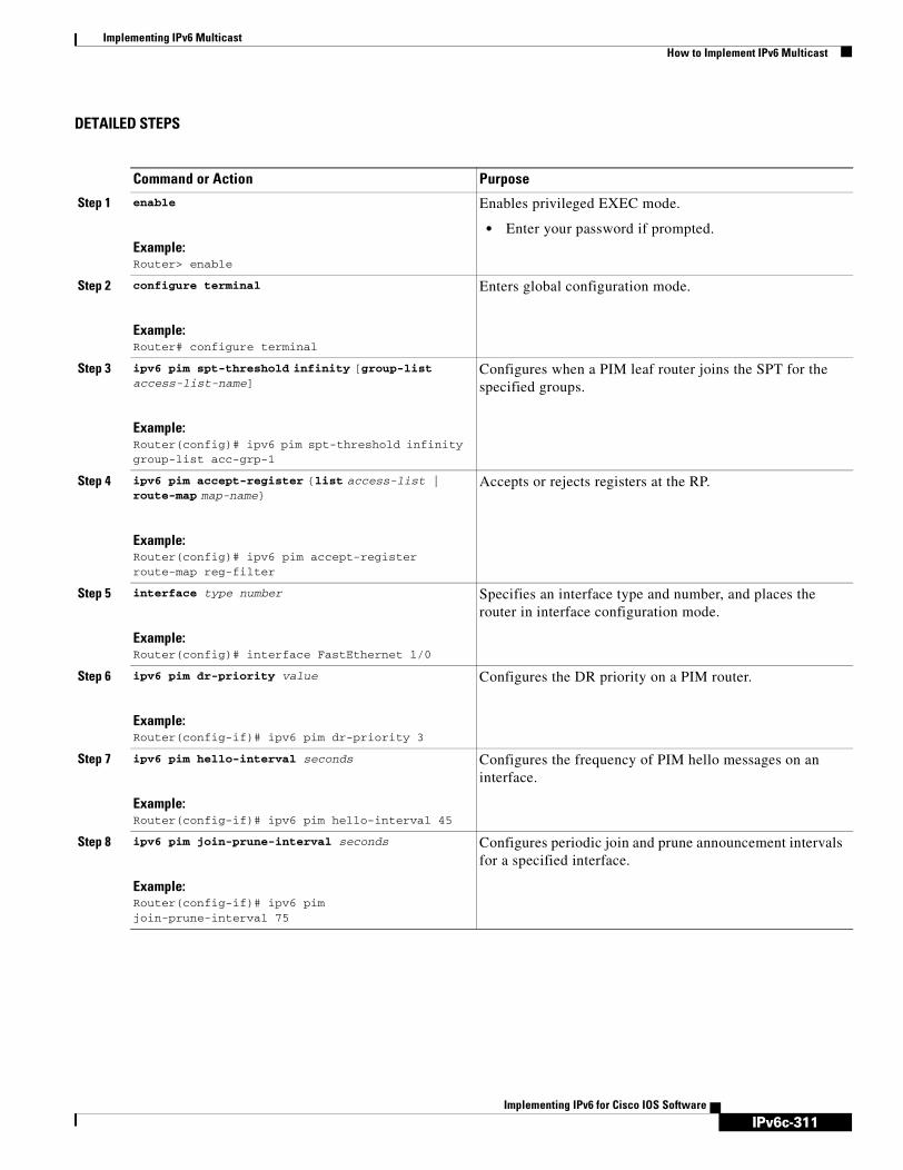
IPv6c-311
Implementing IPv6 MulticastHow to Implement IPv6 Multicast
Implementing IPv6 for Cisco IOS Software
DETAILED STEPS
Command or Action Purpose
Step 1 enable
Example:Router> enable
Enables privileged EXEC mode.
• Enter your password if prompted.
Step 2 configure terminal
Example:Router# configure terminal
Enters global configuration mode.
Step 3 ipv6 pim spt-threshold infinity [group-list access-list-name]
Example:Router(config)# ipv6 pim spt-threshold infinity group-list acc-grp-1
Configures when a PIM leaf router joins the SPT for the specified groups.
Step 4 ipv6 pim accept-register {list access-list | route-map map-name}
Example:Router(config)# ipv6 pim accept-register route-map reg-filter
Accepts or rejects registers at the RP.
Step 5 interface type number
Example:Router(config)# interface FastEthernet 1/0
Specifies an interface type and number, and places the router in interface configuration mode.
Step 6 ipv6 pim dr-priority value
Example:Router(config-if)# ipv6 pim dr-priority 3
Configures the DR priority on a PIM router.
Step 7 ipv6 pim hello-interval seconds
Example:Router(config-if)# ipv6 pim hello-interval 45
Configures the frequency of PIM hello messages on an interface.
Step 8 ipv6 pim join-prune-interval seconds
Example:Router(config-if)# ipv6 pim join-prune-interval 75
Configures periodic join and prune announcement intervals for a specified interface.

IPv6c-312
Implementing IPv6 MulticastHow to Implement IPv6 Multicast
Implementing IPv6 for Cisco IOS Software
Configuring Bidirectional PIM and Displaying Bidirectional PIM Information
This task explains how to configure bidirectional PIM and use show commands to display bidirectional PIM information.
SUMMARY STEPS
1. enable
2. configure terminal
3. ipv6 pim rp-address ipv6-address bidir
4. exit
5. show ipv6 pim df [interface-type interface-number] [rp-address]
6. show ipv6 pim df winner [interface-type interface-number] [rp-address]
DETAILED STEPS
Step 9 exit
Example:Router(config-if)# exit
Enter this command twice to exit interface configuration mode and enter privileged EXEC mode.
Step 10 show ipv6 pim join-prune statistic [interface-type]
Example:Router# show ipv6 pim join-prune statistic
Displays the average join-prune aggregation for the most recently aggregated 1000, 10,000, and 50,000 packets for each interface.
Command or Action Purpose
Command or Action Purpose
Step 1 enable
Example:Router> enable
Enables privileged EXEC mode.
• Enter your password if prompted.
Step 2 configure terminal
Example:Router# configure terminal
Enters global configuration mode.
Step 3 ipv6 pim rp-address ipv6-address bidir
Example:Router(config)# ipv6 pim rp-address 2001:0DB8::01:800:200E:8C6C bidir
Configures the address of a PIM RP for a particular group range. Use of the bidir keyword means that the group range will be used for bidirectional shared-tree forwarding.
Step 4 exit
Example:Router(config-if)# exit
Exits global configuration mode, and returns the router to privileged EXEC mode.

IPv6c-313
Implementing IPv6 MulticastHow to Implement IPv6 Multicast
Implementing IPv6 for Cisco IOS Software
Resetting the PIM Traffic Counters
If PIM malfunctions or in order to verify that the expected number of PIM packets are received and sent, the user can clear PIM traffic counters. Once the traffic counters are cleared, the user can enter the show ipv6 pim traffic command to verify that PIM is functioning correctly and that PIM packets are being received and sent correctly.
This task explains how to reset the PIM traffic counters and verify PIM traffic information.
SUMMARY STEPS
1. enable
2. clear ipv6 pim counters
3. show ipv6 pim traffic
DETAILED STEPS
Step 5 show ipv6 pim df [interface-type interface-number] [rp-address]
Example:Router# show ipv6 pim df
Displays the designated forwarder (DF)-election state of each interface for RP.
Step 6 show ipv6 pim df winner [interface-type interface-number] [rp-address]
Example:Router# show ipv6 pim df winner ethernet 1/0 200::1
Displays the DF-election winner on each interface for each RP.
Command or Action Purpose
Command or Action Purpose
Step 1 enable
Example:Router> enable
Enables privileged EXEC mode.
• Enter your password if prompted.
Step 2 clear ipv6 pim counters
Example:Router# clear ipv6 pim counters
Resets the PIM traffic counters.
Step 3 show ipv6 pim traffic
Example:Router# show ipv6 pim traffic
Displays the PIM traffic counters.
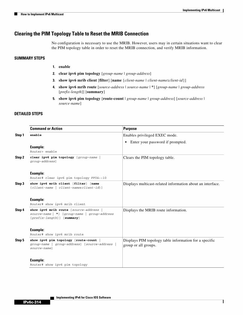
IPv6c-314
Implementing IPv6 MulticastHow to Implement IPv6 Multicast
Implementing IPv6 for Cisco IOS Software
Clearing the PIM Topology Table to Reset the MRIB Connection
No configuration is necessary to use the MRIB. However, users may in certain situations want to clear the PIM topology table in order to reset the MRIB connection, and verify MRIB information.
SUMMARY STEPS
1. enable
2. clear ipv6 pim topology [group-name | group-address]
3. show ipv6 mrib client [filter] [name {client-name | client-name:client-id}]
4. show ipv6 mrib route [source-address | source-name | *] [group-name | group-address [prefix-length]] [summary]
5. show ipv6 pim topology [route-count | group-name | group-address] [source-address | source-name]
DETAILED STEPS
Command or Action Purpose
Step 1 enable
Example:Router> enable
Enables privileged EXEC mode.
• Enter your password if prompted.
Step 2 clear ipv6 pim topology [group-name | group-address]
Example:Router# clear ipv6 pim topology FF04::10
Clears the PIM topology table.
Step 3 show ipv6 mrib client [filter] [name {client-name | client-name:client-id}]
Example:Router# show ipv6 mrib client
Displays multicast-related information about an interface.
Step 4 show ipv6 mrib route [source-address | source-name | *] [group-name | group-address [prefix-length]] [summary]
Example:Router# show ipv6 mrib route
Displays the MRIB route information.
Step 5 show ipv6 pim topology [route-count | group-name | group-address] [source-address | source-name]
Example:Router# show ipv6 pim topology
Displays PIM topology table information for a specific group or all groups.

IPv6c-315
Implementing IPv6 MulticastHow to Implement IPv6 Multicast
Implementing IPv6 for Cisco IOS Software
Configuring a BSRThe following tasks explains how to perform BSR configuration and to verify BSR configuration and information:
• Configuring a BSR and Verifying BSR Information, page 315
• Sending PIM RP Advertisements to the BSR, page 316
• Configuring BSR for Use Within Scoped Zones, page 317
• Configuring BSR Routers to Announce Scope-to-RP Mappings, page 318
Configuring a BSR and Verifying BSR Information
This task describes how to configure a BSR on a specified interface and verify BSR configuration information.
SUMMARY STEPS
1. enable
2. configure terminal
3. ipv6 pim bsr candidate bsr ipv6-address [hash-mask-length] [priority priority-value] [scope scope-value]
4. interface type number
5. ipv6 pim bsr border
6. exit
7. show ipv6 pim bsr {election | rp-cache | candidate-rp}
DETAILED STEPS
Command or Action Purpose
Step 1 enable
Example:Router> enable
Enables privileged EXEC mode.
• Enter your password if prompted.
Step 2 configure terminal
Example:Router# configure terminal
Enters global configuration mode.
Step 3 ipv6 pim bsr candidate bsr ipv6-address [hash-mask-length] [priority priority-value] [scope scope-value]
Example:Router(config)# ipv6 pim bsr candidate bsr 2001:0DB8:3000:3000::42 124 priority 10
Configures a router to be a candidate BSR.

IPv6c-316
Implementing IPv6 MulticastHow to Implement IPv6 Multicast
Implementing IPv6 for Cisco IOS Software
Sending PIM RP Advertisements to the BSR
This task explains how to configure a router to send PIM RP advertisements to the BSR.
SUMMARY STEPS
1. enable
2. configure terminal
3. ipv6 pim bsr candidate rp ipv6-address [group-list access-list-name] [priority priority-value] [interval seconds] [scope scope-value] [bidir]
4. interface type number
5. ipv6 pim bsr border
DETAILED STEPS
Step 4 interface type number
Example:Router(config)# interface FastEthernet 1/0
Specifies an interface type and number, and places the router in interface configuration mode.
Step 5 ipv6 pim bsr border
Example:Router(config-if)# ipv6 pim bsr border
Configures a border for all BSMs of any scope on a specified interface.
Step 6 exit
Example:Router(config-if)# exit
Enter this command twice to exit interface configuration mode and enter privileged EXEC mode.
Step 7 show ipv6 pim bsr {election | rp-cache | candidate-rp}
Example:Router# show ipv6 pim bsr election
Displays information related to PIM BSR protocol processing.
Command or Action Purpose
Command or Action Purpose
Step 1 enable
Example:Router> enable
Enables privileged EXEC mode.
• Enter your password if prompted.
Step 2 configure terminal
Example:Router# configure terminal
Enters global configuration mode.
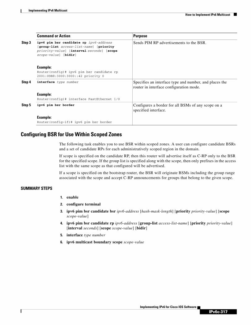
IPv6c-317
Implementing IPv6 MulticastHow to Implement IPv6 Multicast
Implementing IPv6 for Cisco IOS Software
Configuring BSR for Use Within Scoped Zones
The following task enables you to use BSR within scoped zones. A user can configure candidate BSRs and a set of candidate RPs for each administratively scoped region in the domain.
If scope is specified on the candidate RP, then this router will advertise itself as C-RP only to the BSR for the specified scope. If the group list is specified along with the scope, then only prefixes in the access list with the same scope as that configured will be advertised.
If a scope is specified on the bootstrap router, the BSR will originate BSMs including the group range associated with the scope and accept C-RP announcements for groups that belong to the given scope.
SUMMARY STEPS
1. enable
2. configure terminal
3. ipv6 pim bsr candidate bsr ipv6-address [hash-mask-length] [priority priority-value] [scope scope-value]
4. ipv6 pim bsr candidate rp ipv6-address [group-list access-list-name] [priority priority-value] [interval seconds] [scope scope-value] [bidir]
5. interface type number
6. ipv6 multicast boundary scope scope-value
Step 3 ipv6 pim bsr candidate rp ipv6-address [group-list access-list-name] [priority priority-value] [interval seconds] [scope scope-value] [bidir]
Example:Router(config)# ipv6 pim bsr candidate rp 2001:0DB8:3000:3000::42 priority 0
Sends PIM RP advertisements to the BSR.
Step 4 interface type number
Example:Router(config)# interface FastEthernet 1/0
Specifies an interface type and number, and places the router in interface configuration mode.
Step 5 ipv6 pim bsr border
Example:Router(config-if)# ipv6 pim bsr border
Configures a border for all BSMs of any scope on a specified interface.
Command or Action Purpose

IPv6c-318
Implementing IPv6 MulticastHow to Implement IPv6 Multicast
Implementing IPv6 for Cisco IOS Software
DETAILED STEPS
Configuring BSR Routers to Announce Scope-to-RP Mappings
IPv6 BSR routers can be statically configured to announce scope-to-RP mappings directly instead of learning them from candidate-RP messages. A user might want to configure a BSR router to announce scope-to-RP mappings so that an RP that does not support BSR is imported into the BSR. Enabling this feature also allows an RP positioned outside the enterprise’s BSR domain to be learned by the known remote RP on the local candidate BSR routers.
SUMMARY STEPS
1. enable
2. configure terminal
Command or Action Purpose
Step 1 enable
Example:Router> enable
Enables privileged EXEC mode.
• Enter your password if prompted.
Step 2 configure terminal
Example:Router# configure terminal
Enters global configuration mode.
Step 3 ipv6 pim bsr candidate bsr ipv6-address [hash-mask-length] [priority priority-value] [scope scope-value]
Example:Router(config)# ipv6 pim bsr candidate bsr 2001:0DB8:1:1:4 scope 6
Configures a router to be a candidate BSR.
Step 4 ipv6 pim bsr candidate rp ipv6-address [group-list access-list-name] [priority priority-value] [interval seconds] [scope scope-value] [bidir]
Example:Router(config)# ipv6 pim bsr candidate rp 2001:0DB8:1:1:1 group-list list scope 6
Configures the candidate RP to send PIM RP advertisements to the BSR.
Step 5 interface type number
Example:Router(config)# interface FastEthernet 1/0
Specifies an interface type and number, and places the router in interface configuration mode.
Step 6 ipv6 multicast boundary scope scope-value
Example:Router(config-if)# ipv6 multicast boundary scope 6
Configures a multicast boundary on the interface for a specified scope.

IPv6c-319
Implementing IPv6 MulticastHow to Implement IPv6 Multicast
Implementing IPv6 for Cisco IOS Software
3. ipv6 pim bsr announced rp ipv6-address [group-list access-list-name] [priority priority-value] [bidir] [scope scope-value]
DETAILED STEPS
Configuring SSM Mapping When the SSM mapping feature is enabled, DNS-based SSM mapping is automatically enabled, which means that the router will look up the source of a multicast MLD version 1 report from a DNS server.
You can use either DNS-based or static SSM mapping, depending on your router configuration. If you choose to use static SSM mapping, you can configure multiple static SSM mappings. If multiple static SSM mappings are configured, the source addresses of all matching access lists will be used.
This task explains how to enable SSM mapping, disable DNS-based mapping, and configure static SSM mapping.
Restrictions
To use DNS-based SSM mapping, the router needs to find at least one correctly configured DNS server, to which the router may be directly attached.
SUMMARY STEPS
1. enable
2. configure terminal
3. ipv6 mld [vrf vrf-name] ssm-map enable
4. no ipv6 mld [vrf vrf-name] ssm-map query dns
5. ipv6 mld ssm-map [vrf vrf-name] static access-list source-address
6. exit
Command or Action Purpose
Step 1 enable
Example:Router> enable
Enables privileged EXEC mode.
• Enter your password if prompted.
Step 2 configure terminal
Example:Router# configure terminal
Enters global configuration mode.
Step 3 ipv6 pim bsr announced rp ipv6-address [group-list access-list-name] [priority priority-value] [bidir] [scope scope-value]
Example:Router(config)# ipv6 pim bsr announced rp 2001:0DB8:3000:3000::42 priority 0
Announces scope-to-RP mappings directly from the BSR for the specified candidate RP.

IPv6c-320
Implementing IPv6 MulticastHow to Implement IPv6 Multicast
Implementing IPv6 for Cisco IOS Software
7. show ipv6 mld ssm-map [source-address]
DETAILED STEPS
Configuring Static MroutesThis task explains how to configure a static multicast route and verify static mroute information. Static multicast routes (mroutes) in IPv6 can be implemented as an extension of IPv6 static routes. You can configure your router to use a static route for unicast routing only, to use a static multicast route for multicast RPF selection only, or to use a static route for both unicast routing and multicast RPF selection.
Command or Action Purpose
Step 1 enable
Example:Router> enable
Enables privileged EXEC mode.
• Enter your password if prompted.
Step 2 configure terminal
Example:Router# configure terminal
Enters global configuration mode.
Step 3 ipv6 mld [vrf vrf-name] ssm-map enable
Example:Router(config)# ipv6 mld ssm-map enable
Enables the SSM mapping feature for groups in the configured SSM range.
Step 4 no ipv6 mld [vrf vrf-name] ssm-map query dns
Example:Router(config)# no ipv6 mld ssm-map query dns
Disables DNS-based SSM mapping.
Step 5 ipv6 mld ssm-map [vrf vrf-name] static access-list source-address
Example:Router(config)# ipv6 mld ssm-map static
SSM_MAP_ACL_2 2001:0DB8:1::1
Configures static SSM mappings.
Step 6 exit
Example:Router(config-if)# exit
Exits global configuration mode, and returns the router to privileged EXEC mode.
Step 7 show ipv6 mld ssm-map [source-address]
Example:Router# show ipv6 mld ssm-map
Displays SSM mapping information.

IPv6c-321
Implementing IPv6 MulticastHow to Implement IPv6 Multicast
Implementing IPv6 for Cisco IOS Software
SUMMARY STEPS
1. enable
2. configure terminal
3. ipv6 route ipv6-prefix/prefix-length {ipv6-address | interface-type interface-number [ipv6-address]} [administrative-distance] [administrative-multicast-distance | unicast | multicast] [tag tag]
4. exit
5. show ipv6 mroute [link-local | [group-name | group-address [source-address | source-name]] [summary] [count]
6. show ipv6 mroute [link-local | group-name | group-address] active [kbps]
7. show ipv6 rpf ipv6-prefix
DETAILED STEPS
Command or Action Purpose
Step 1 enable
Example:Router> enable
Enables privileged EXEC mode.
• Enter your password if prompted.
Step 2 configure terminal
Example:Router# configure terminal
Enters global configuration mode.
Step 3 ipv6 route ipv6-prefix/prefix-length {ipv6-address | interface-type interface-number [ipv6-address]} [administrative-distance] [administrative-multicast-distance | unicast | multicast] [tag tag]
Example:Router(config)# ipv6 route 2001:0DB8::/64 6::6 100
Establishes static IPv6 routes. The example shows a static route used for both unicast routing and multicast RPF selection.
Step 4 exit
Example:Router(config-if)# exit
Exits global configuration mode, and returns the router to privileged EXEC mode.
Step 5 show ipv6 mroute [link-local | [group-name | group-address [source-address | source-name]] [summary] [count]
Example:Router# show ipv6 mroute ff07::1
Displays the contents of the IPv6 multicast routing table.

IPv6c-322
Implementing IPv6 MulticastHow to Implement IPv6 Multicast
Implementing IPv6 for Cisco IOS Software
Configuring IPv6 Multiprotocol BGP The following tasks explain how to configure IPv6 multiprotocol BGP to perform multicast routing. Note that these multicast BGP tasks related to IPv6 multicast are similar to those multicast BGP tasks for IPv6 unicast.
• Configuring an IPv6 Peer Group to Perform Multicast BGP Routing, page 322
• Advertising Routes into IPv6 Multiprotocol BGP, page 324
• Redistributing Prefixes into IPv6 Multiprotocol BGP, page 326
• Assigning a BGP Administrative Distance, page 327
• Generating Translate Updates for IPv6 Multicast BGP, page 328
• Resetting BGP Sessions, page 329
• Clearing External BGP Peers, page 330
• Clearing IPv6 BGP Route Dampening Information, page 331
• Clearing IPv6 BGP Flap Statistics, page 331
Configuring an IPv6 Peer Group to Perform Multicast BGP Routing
The following tasks explain how to configure an IPv6 peer group to perform multicast BGP routing.
SUMMARY STEPS
1. enable
2. configure terminal
3. router bgp autonomous-system-number
4. neighbor peer-group-name peer-group
5. neighbor ipv6-address remote-as autonomous-system-number
6. address-family ipv6 [unicast | multicast]
7. neighbor {ip-address | peer-group-name | ipv6-address} activate
8. neighbor ipv6-address peer-group peer-group-name
Step 6 show ipv6 mroute [link-local | group-name | group-address] active [kbps]
Example:Router# show ipv6 mroute active
Displays the active multicast streams on the router.
Step 7 show ipv6 rpf ipv6-prefix
Example:Router# show ipv6 rpf 2001:0DB8::1:1:2
Checks RPF information for a given unicast host address and prefix.
Command or Action Purpose

IPv6c-323
Implementing IPv6 MulticastHow to Implement IPv6 Multicast
Implementing IPv6 for Cisco IOS Software
DETAILED STEPS
Command or Action Purpose
Step 1 enable
Example:Router> enable
Enables privileged EXEC mode.
• Enter your password if prompted.
Step 2 configure terminal
Example:Router# configure terminal
Enters global configuration mode.
Step 3 router bgp autonomous-system-number
Example:Router(config)# router bgp 65000
Enters router configuration mode for the specified BGP routing process.
Step 4 neighbor peer-group-name peer-group
Example:Router(config-router)# neighbor group1 peer-group
Creates an multicast BGP peer group.
Step 5 neighbor ipv6-address remote-as autonomous-system-number
Example:Router(config-router)# neighbor 2001:0DB8:0:CC00::1 remote-as 64600
Adds the IPv6 address of the neighbor in the specified autonomous system to the IPv6 multicast BGP neighbor table of the local router.
• The ipv6-address argument in the neighbor remote-as command must be in the form documented in RFC 2373 where the address is specified in hexadecimal using 16-bit values between colons.
Step 6 address-family ipv6 [unicast | multicast]
Example:Router(config-router)# address-family ipv6 multicast
Specifies the IPv6 address family, and enters address family configuration mode.
• The unicast keyword specifies the IPv6 unicast address family. By default, the router is placed in configuration mode for the IPv6 unicast address family if the unicast keyword is not specified with the address-family ipv6 command.
• The multicast keyword specifies IPv6 multicast address prefixes.

IPv6c-324
Implementing IPv6 MulticastHow to Implement IPv6 Multicast
Implementing IPv6 for Cisco IOS Software
What to Do Next
Refer to the section “Configuring an IPv6 Multiprotocol BGP Peer Group” in the Implementing Multiprotocol BGP for IPv6 implementation guide and the “Configure BGP Peer Groups” section of the “Configuring BGP” chapter in the Cisco IOS IP Configuration Guide, Release 12.4, for more information on assigning options to peer groups and making a BGP or multicast BGP neighbor a member of a peer group.
Advertising Routes into IPv6 Multiprotocol BGP
This task explains how to advertise (inject) a prefix into IPv6 multicast BGP. Note that this task and other multicast BGP tasks related to IPv6 multicast are similar to those multicast BGP tasks for IPv6 unicast.
SUMMARY STEPS
1. enable
2. configure terminal
3. router bgp autonomous-system-number
4. address-family ipv6 [unicast | multicast]
5. network ipv6-address/prefix-length
Step 7 neighbor {ip-address | peer-group-name | ipv6-address} activate
Example:Router(config-router-af)# neighbor 2001:0DB8:0:CC00::1 activate
Enables the neighbor to exchange prefixes for the specified family type with the neighbor and the local router.
• To avoid extra configuration steps for each neighbor, use the neighbor activate command with the peer-group-name argument as an alternative in this step.
Step 8 neighbor ipv6-address peer-group peer-group-name
Example:Router(config-router-af)# neighbor 2001:0DB8:0:CC00::1 peer-group group1
Assigns the IPv6 address of a BGP neighbor to a peer group.
Command or Action Purpose

IPv6c-325
Implementing IPv6 MulticastHow to Implement IPv6 Multicast
Implementing IPv6 for Cisco IOS Software
DETAILED STEPS
What to Do Next
Refer to the section “Advertising Routes into IPv6 Multiprotocol BGP” in the Implementing Multiprotocol BGP for IPv6 implementation guide for more information on assigning options to peer groups and making a BGP or multicast BGP neighbor a member of a peer group.
Command or Action Purpose
Step 1 enable
Example:Router> enable
Enables privileged EXEC mode.
• Enter your password if prompted.
Step 2 configure terminal
Example:Router# configure terminal
Enters global configuration mode.
Step 3 router bgp autonomous-system-number
Example:Router(config)# router bgp 65000
Enters router configuration mode for the specified BGP routing process.
Step 4 address-family ipv6 [unicast | multicast]
Example:Router(config-router)# address-family ipv6 multicast
Specifies the IPv6 address family, and enters address family configuration mode.
• The unicast keyword specifies the IPv6 unicast address family. By default, the router is placed in configuration mode for the IPv6 unicast address family if the unicast keyword is not specified with the address-family ipv6 command.
• The multicast keyword specifies IPv6 multicast address prefixes.
Step 5 network ipv6-address/prefix-length
Example:Router(config-router-af)# network 2001:0DB8::/24
Advertises (injects) the specified prefix into the IPv6 BGP database. (The routes must first be found in the IPv6 unicast routing table.)
• Specifically, the prefix is injected into the database for the address family specified in the previous step.
• Routes are tagged from the specified prefix as “local origin.”
• The ipv6-prefix argument in the network command must be in the form documented in RFC 2373 where the address is specified in hexadecimal using 16-bit values between colons.
• The prefix-length argument is a decimal value that indicates how many of the high-order contiguous bits of the address comprise the prefix (the network portion of the address). A slash mark must precede the decimal value.

IPv6c-326
Implementing IPv6 MulticastHow to Implement IPv6 Multicast
Implementing IPv6 for Cisco IOS Software
Redistributing Prefixes into IPv6 Multiprotocol BGP
This task explains how to redistribute (inject) prefixes from another routing protocol into IPv6 multicast BGP. Note that this task and other multicast BGP tasks related to IPv6 multicast are similar to those multicast BGP tasks for IPv6 unicast.
SUMMARY STEPS
1. enable
2. configure terminal
3. router bgp autonomous-system-number
4. address-family ipv6 [unicast | multicast]
5. redistribute protocol [process-id] [level-1 | level-1-2 | level-2] [metric metric-value] [metric-type {internal | external}] [route-map map-name]
DETAILED STEPS
Command or Action Purpose
Step 1 enable
Example:Router> enable
Enables privileged EXEC mode.
• Enter your password if prompted.
Step 2 configure terminal
Example:Router# configure terminal
Enters global configuration mode.
Step 3 router bgp autonomous-system-number
Example:Router(config)# router bgp 65000
Enters router configuration mode for the specified BGP routing process.
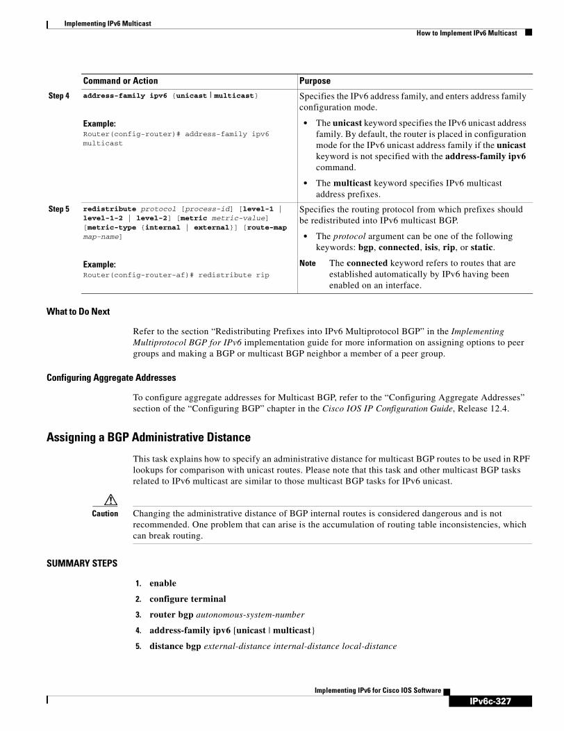
IPv6c-327
Implementing IPv6 MulticastHow to Implement IPv6 Multicast
Implementing IPv6 for Cisco IOS Software
What to Do Next
Refer to the section “Redistributing Prefixes into IPv6 Multiprotocol BGP” in the Implementing Multiprotocol BGP for IPv6 implementation guide for more information on assigning options to peer groups and making a BGP or multicast BGP neighbor a member of a peer group.
Configuring Aggregate Addresses
To configure aggregate addresses for Multicast BGP, refer to the “Configuring Aggregate Addresses” section of the “Configuring BGP” chapter in the Cisco IOS IP Configuration Guide, Release 12.4.
Assigning a BGP Administrative Distance
This task explains how to specify an administrative distance for multicast BGP routes to be used in RPF lookups for comparison with unicast routes. Please note that this task and other multicast BGP tasks related to IPv6 multicast are similar to those multicast BGP tasks for IPv6 unicast.
Caution Changing the administrative distance of BGP internal routes is considered dangerous and is not recommended. One problem that can arise is the accumulation of routing table inconsistencies, which can break routing.
SUMMARY STEPS
1. enable
2. configure terminal
3. router bgp autonomous-system-number
4. address-family ipv6 [unicast | multicast}
5. distance bgp external-distance internal-distance local-distance
Step 4 address-family ipv6 {unicast | multicast}
Example:Router(config-router)# address-family ipv6 multicast
Specifies the IPv6 address family, and enters address family configuration mode.
• The unicast keyword specifies the IPv6 unicast address family. By default, the router is placed in configuration mode for the IPv6 unicast address family if the unicast keyword is not specified with the address-family ipv6 command.
• The multicast keyword specifies IPv6 multicast address prefixes.
Step 5 redistribute protocol [process-id] [level-1 | level-1-2 | level-2] [metric metric-value] [metric-type {internal | external}] [route-map map-name]
Example:Router(config-router-af)# redistribute rip
Specifies the routing protocol from which prefixes should be redistributed into IPv6 multicast BGP.
• The protocol argument can be one of the following keywords: bgp, connected, isis, rip, or static.
Note The connected keyword refers to routes that are established automatically by IPv6 having been enabled on an interface.
Command or Action Purpose

IPv6c-328
Implementing IPv6 MulticastHow to Implement IPv6 Multicast
Implementing IPv6 for Cisco IOS Software
DETAILED STEPS
Generating Translate Updates for IPv6 Multicast BGP
This task explains how to generate IPv6 multicast BGP updates that correspond to unicast IPv6 updates received from a peer.
The multicast BGP translate-update feature generally is used in an multicast BGP-capable router that peers with a customer site that has only a BGP-capable router; the customer site has not or cannot upgrade its router to an multicast BGP-capable image. Because the customer site cannot originate multicast BGP advertisements, the router with which it peers will translate the BGP prefixes into multicast BGP prefixes, which are used for multicast-source RPF lookup.
SUMMARY STEPS
1. enable
2. configure terminal
3. router bgp autonomous-system-number
4. address-family ipv6 [unicast | multicast}
5. neighbor ipv6-address translate-update ipv6 multicast [unicast]
Command or Action Purpose
Step 1 enable
Example:Router> enable
Enables privileged EXEC mode.
• Enter your password if prompted.
Step 2 configure terminal
Example:Router# configure terminal
Enters global configuration mode.
Step 3 router bgp autonomous-system-number
Example:Router(config)# router bgp 100
Enters router configuration mode for the specified routing process.
Step 4 address-family ipv6 [unicast | multicast}
Example:Router(config-router)# address-family ipv6 multicast
Enters address family configuration mode for configuring routing sessions such as BGP that use standard IPv6 address prefixes.
Step 5 distance bgp external-distance internal-distance local-distance
Example:Router(config-router)# distance bgp 20 20 200
Assigns a BGP administrative distance.

IPv6c-329
Implementing IPv6 MulticastHow to Implement IPv6 Multicast
Implementing IPv6 for Cisco IOS Software
DETAILED STEPS
Resetting BGP Sessions
This task explains how to reset IPv6 BGP sessions.
SUMMARY STEPS
1. enable
2. clear bgp ipv6 {unicast | multicast} {* | autonomous-system-number | ip-address | ipv6-address | peer-group-name} [soft] [in | out]
Command or Action Purpose
Step 1 enable
Example:Router> enable
Enables privileged EXEC mode.
• Enter your password if prompted.
Step 2 configure terminal
Example:Router# configure terminal
Enters global configuration mode.
Step 3 router bgp autonomous-system-number
Example:Router(config)# router bgp 100
Enters router configuration mode for the specified routing process.
Step 4 address-family ipv6 [unicast | multicast}
Example:Router(config-router)# address-family ipv6 multicast
Enters address family configuration mode for configuring routing sessions such as BGP that use standard IPv6 address prefixes.
Step 5 neighbor ipv6-address translate-update ipv6 multicast [unicast]
Example:Router(config-router)# neighbor 2001:0DB8:7000::2 translate-update ipv6 multicast
Generates multiprotocol IPv6 BGP updates that correspond to unicast IPv6 updates received from a peer.

IPv6c-330
Implementing IPv6 MulticastHow to Implement IPv6 Multicast
Implementing IPv6 for Cisco IOS Software
DETAILED STEPS
Clearing External BGP Peers
This task explains how to clear external BGP peers and members of an IPv6 BGP peer group.
SUMMARY STEPS
1. enable
2. clear bgp ipv6 {unicast | multicast} external [soft] [in | out]
3. clear bgp ipv6 {unicast | multicast} peer-group [name]
DETAILED STEPS
Command or Action Purpose
Step 1 enable
Example:Router> enable
Enables privileged EXEC mode.
• Enter your password if prompted.
Step 2 clear bgp ipv6 {unicast | multicast} {* | autonomous-system-number | ip-address | ipv6-address | peer-group-name} [soft] [in | out]
Example:Router# clear bgp ipv6 unicast peer-group marketing soft out
Resets IPv6 BGP sessions.
Command or Action Purpose
Step 1 enable
Example:Router> enable
Enables privileged EXEC mode.
• Enter your password if prompted.
Step 2 clear bgp ipv6 {unicast | multicast} external [soft] [in | out]
Example:Router# clear bgp ipv6 unicast external soft in
Clears external IPv6 BGP peers.
Step 3 clear bgp ipv6 {unicast | multicast} peer-group [name]
Example:Router# clear bgp ipv6 unicast peer-group
Clears all members of an IPv6 BGP peer group.

IPv6c-331
Implementing IPv6 MulticastHow to Implement IPv6 Multicast
Implementing IPv6 for Cisco IOS Software
Clearing IPv6 BGP Route Dampening Information
This task explains how to clear IPv6 BGP route dampening information and how to unsuppress suppressed routes.
SUMMARY STEPS
1. enable
2. clear bgp ipv6 {unicast | multicast} dampening [ipv6-prefix/prefix-length]
DETAILED STEPS
Clearing IPv6 BGP Flap Statistics
This task explains how to clear IPv6 BGP flap statistics.
SUMMARY STEPS
1. enable
2. clear bgp ipv6 {unicast | multicast} flap-statistics [ipv6-prefix/prefix-length | regexp regexp | filter-list list]
Command or Action Purpose
Step 1 enable
Example:Router> enable
Enables privileged EXEC mode.
• Enter your password if prompted.
Step 2 clear bgp ipv6 {unicast | multicast} dampening [ipv6-prefix/prefix-length]
Example:Router# clear bgp ipv6 unicast dampening 2001:0DB8:7000::/64
Clears IPv6 BGP route dampening information and unsuppress the suppressed routes.

IPv6c-332
Implementing IPv6 MulticastHow to Implement IPv6 Multicast
Implementing IPv6 for Cisco IOS Software
DETAILED STEPS
Using MFIB in IPv6 Multicast Multicast forwarding is automatically enabled when IPv6 multicast routing is enabled. The following tasks explain how to display information to verify MFIB configuration and operation and reset MFIB as needed.
• Verifying MFIB Operation in IPv6 Multicast, page 332
• Resetting MFIB Traffic Counters, page 333
Verifying MFIB Operation in IPv6 Multicast
This task explains how to display and verify MFIB use in IPv6 multicast.
SUMMARY STEPS
1. enable
2. show ipv6 mfib [group-name | group-address [source-name | source-address]] [verbose]
3. show ipv6 mfib [group-name | group-address] active [kbps]
4. show ipv6 mfib [group-name | group-address [source-name | source-address]] count
5. show ipv6 mfib interface
6. show ipv6 mfib status
7. show ipv6 mfib summary
Command or Action Purpose
Step 1 enable
Example:Router> enable
Enables privileged EXEC mode.
• Enter your password if prompted.
Step 2 clear bgp ipv6 {unicast | multicast} flap-statistics [ipv6-prefix/prefix-length | regexp regexp | filter-list list]
Example:Router# clear bgp ipv6 multicast flap-statistics
Clears IPv6 BGP flap statistics.

IPv6c-333
Implementing IPv6 MulticastHow to Implement IPv6 Multicast
Implementing IPv6 for Cisco IOS Software
DETAILED STEPS
Resetting MFIB Traffic Counters
This task explains how to reset all active MFIB traffic counters.
SUMMARY STEPS
1. enable
2. clear ipv6 mfib counters [group-name | group-address [source-address | source-name]]
Command or Action Purpose
Step 1 enable
Example:Router> enable
Enables privileged EXEC mode.
• Enter your password if prompted.
Step 2 show ipv6 mfib [group-name | group-address [source-name | source-address]] [verbose]
Example:Router# show ipv6 mfib
Displays the forwarding entries and interfaces in the IPv6 MFIB.
Step 3 show ipv6 mfib [group-name | group-address] active [kbps]
Example:Router# show ipv6 mfib active
Displays the rate at which active sources are sending to multicast groups.
Step 4 show ipv6 mfib [group-name | group-address [source-name | source-address]] count
Example:Router# show ipv6 mfib count
Displays summary traffic statistics from the MFIB about the group and source.
Step 5 show ipv6 mfib interface
Example:Router# show ipv6 mfib interface
Displays information about IPv6 multicast-enabled interfaces and their forwarding status.
Step 6 show ipv6 mfib status
Example:Router# show ipv6 mfib status
Displays general MFIB configuration and operational status.
Step 7 show ipv6 mfib summary
Example:Router# show ipv6 mfib summary
Displays summary information about the number of IPv6 MFIB entries and interfaces.
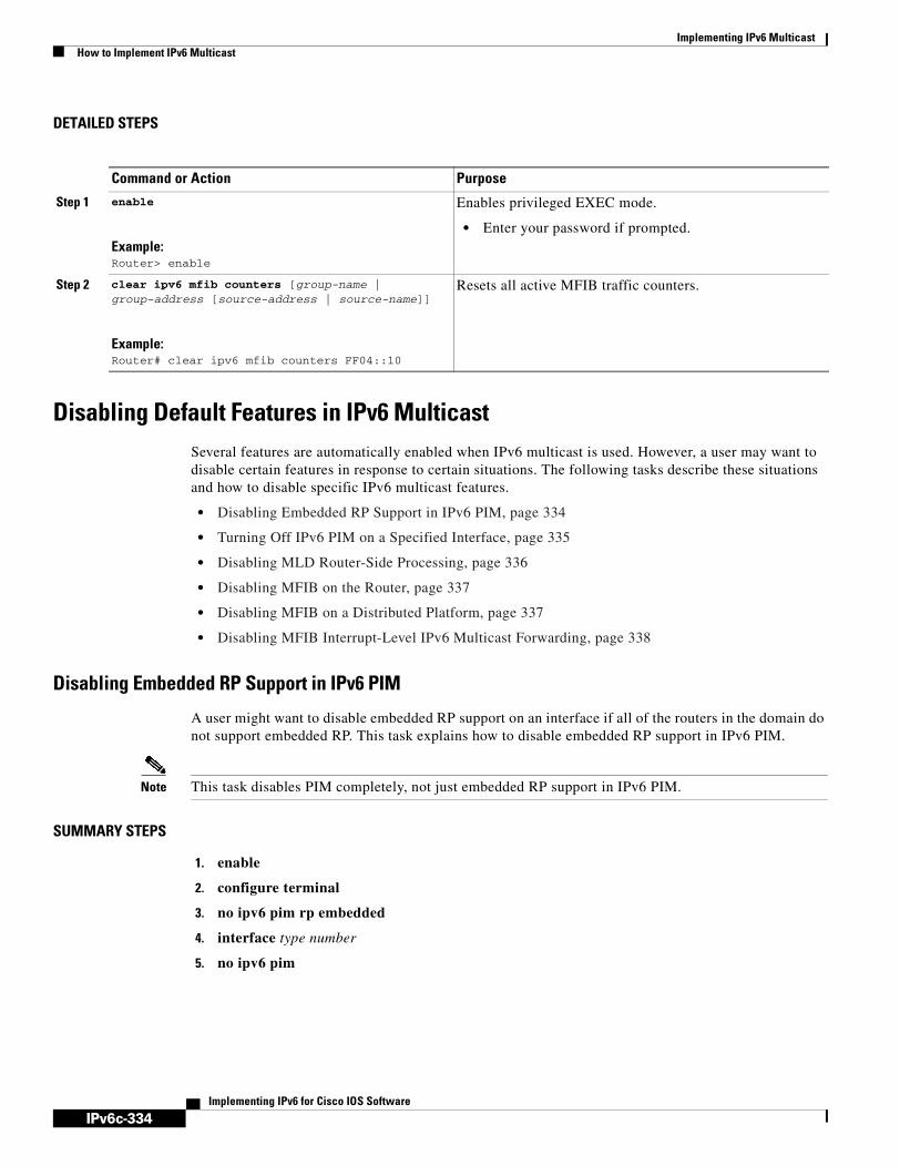
IPv6c-334
Implementing IPv6 MulticastHow to Implement IPv6 Multicast
Implementing IPv6 for Cisco IOS Software
DETAILED STEPS
Disabling Default Features in IPv6 MulticastSeveral features are automatically enabled when IPv6 multicast is used. However, a user may want to disable certain features in response to certain situations. The following tasks describe these situations and how to disable specific IPv6 multicast features.
• Disabling Embedded RP Support in IPv6 PIM, page 334
• Turning Off IPv6 PIM on a Specified Interface, page 335
• Disabling MLD Router-Side Processing, page 336
• Disabling MFIB on the Router, page 337
• Disabling MFIB on a Distributed Platform, page 337
• Disabling MFIB Interrupt-Level IPv6 Multicast Forwarding, page 338
Disabling Embedded RP Support in IPv6 PIM
A user might want to disable embedded RP support on an interface if all of the routers in the domain do not support embedded RP. This task explains how to disable embedded RP support in IPv6 PIM.
Note This task disables PIM completely, not just embedded RP support in IPv6 PIM.
SUMMARY STEPS
1. enable
2. configure terminal
3. no ipv6 pim rp embedded
4. interface type number
5. no ipv6 pim
Command or Action Purpose
Step 1 enable
Example:Router> enable
Enables privileged EXEC mode.
• Enter your password if prompted.
Step 2 clear ipv6 mfib counters [group-name | group-address [source-address | source-name]]
Example:Router# clear ipv6 mfib counters FF04::10
Resets all active MFIB traffic counters.

IPv6c-335
Implementing IPv6 MulticastHow to Implement IPv6 Multicast
Implementing IPv6 for Cisco IOS Software
DETAILED STEPS
Turning Off IPv6 PIM on a Specified Interface
A user might only want specified interfaces to perform IPv6 multicast and will therefore want to turn off PIM on a specified interface. This task explains how to turn off PIM on a specified interface.
SUMMARY STEPS
1. enable
2. configure terminal
3. interface type number
4. no ipv6 pim
Command or Action Purpose
Step 1 enable
Example:Router> enable
Enables privileged EXEC mode.
• Enter your password if prompted.
Step 2 configure terminal
Example:Router# configure terminal
Enters global configuration mode.
Step 3 no ipv6 pim rp embedded
Example:Router(config)# no ipv6 pim rp embedded
Disables embedded RP support in IPv6 PIM.
Step 4 interface type number
Example:Router(config)# interface FastEthernet 1/0
Specifies an interface type and number, and places the router in interface configuration mode.
Step 5 no ipv6 pim
Example:Router(config-if)# no ipv6 pim
Turns off IPv6 PIM on a specified interface.

IPv6c-336
Implementing IPv6 MulticastHow to Implement IPv6 Multicast
Implementing IPv6 for Cisco IOS Software
DETAILED STEPS
Disabling MLD Router-Side Processing
A user might only want specified interfaces to perform IPv6 multicast and will therefore want to turn off MLD router-side processing on a specified interface. Use the following task to disable MLD router-side processing on a specified interface.
SUMMARY STEPS
1. enable
2. configure terminal
3. interface type number
4. no ipv6 mld router
DETAILED STEPS
Command or Action Purpose
Step 1 enable
Example:Router> enable
Enables privileged EXEC mode.
• Enter your password if prompted.
Step 2 configure terminal
Example:Router# configure terminal
Enters global configuration mode.
Step 3 interface type number
Example:Router(config)# interface FastEthernet 1/0
Specifies an interface type and number, and places the router in interface configuration mode.
Step 4 no ipv6 pim
Example:Router(config-if)# no ipv6 pim
Turns off IPv6 PIM on a specified interface.
Command or Action Purpose
Step 1 enable
Example:Router> enable
Enables privileged EXEC mode.
• Enter your password if prompted.
Step 2 configure terminal
Example:Router# configure terminal
Enters global configuration mode.

IPv6c-337
Implementing IPv6 MulticastHow to Implement IPv6 Multicast
Implementing IPv6 for Cisco IOS Software
Disabling MFIB on the Router
Multicast forwarding is automatically enabled when IPv6 multicast routing is enabled. However, a user may want to disable multicast forwarding on the router. The following task explains how to disable multicast forwarding on the router:
SUMMARY STEPS
1. enable
2. configure terminal
3. no ipv6 mfib
DETAILED STEPS
Disabling MFIB on a Distributed Platform
Multicast forwarding is automatically enabled when IPv6 multicast routing is enabled. However, a user may want to disable multicast forwarding on a distributed platform. The following task explains how to disable multicast forwarding on a distributed platform:
Step 3 interface type number
Example:Router(config)# interface FastEthernet 1/0
Specifies an interface type and number, and places the router in interface configuration mode.
Step 4 no ipv6 mld router
Example:Router(config-if)# no ipv6 mld router
Disables MLD router-side processing on a specified interface.
Command or Action Purpose
Command or Action Purpose
Step 1 enable
Example:Router> enable
Enables privileged EXEC mode.
• Enter your password if prompted.
Step 2 configure terminal
Example:Router# configure terminal
Enters global configuration mode.
Step 3 no ipv6 mfib
Example:Router(config)# no ipv6 mfib
Disables IPv6 multicast forwarding on the router.

IPv6c-338
Implementing IPv6 MulticastHow to Implement IPv6 Multicast
Implementing IPv6 for Cisco IOS Software
SUMMARY STEPS
1. enable
2. configure terminal
3. ipv6 mfib-mode centralized-only
DETAILED STEPS
Disabling MFIB Interrupt-Level IPv6 Multicast Forwarding
Multicast Forwarding Information Base (MFIB) interrupt-level IPv6 multicast forwarding of outgoing packets on a specific interface is enabled on interfaces that support Cisco Express Forwarding (CEF). However, a user may want to disable MFIB interrupt-level forwarding on a specified interface. The following task explains how to disable this feature:
SUMMARY STEPS
1. enable
2. configure terminal
3. interface type number
4. no ipv6 mfib fast
Command or Action Purpose
Step 1 enable
Example:Router> enable
Enables privileged EXEC mode.
•Enter your password if prompted.
Step 2 configure terminal
Example:Router# configure terminal
Enters global configuration mode.
Step 3 ipv6 mfib-mode centralized-only
Example:Router(config)# ipv6 mfib-mode centralized-only
Disables distributed forwarding on a distributed platform.

IPv6c-339
Implementing IPv6 MulticastHow to Implement IPv6 Multicast
Implementing IPv6 for Cisco IOS Software
DETAILED STEPS
Troubleshooting IPv6 MulticastUse debug commands to help you troubleshoot an IPv6 multicast environment. This task describes the commands to display debugging information on IPv6 multicast.
SUMMARY STEPS
1. enable
2. debug ipv6 mfib [adjacency | signal | db | init | mrib | pak | ps] [group-name | group-address]
3. debug ipv6 mld [group-name | group-address | interface-type]
4. debug ipv6 mld explicit [group-name | group-address]
5. debug ipv6 pim [group-name | group-address | interface-type | neighbor | bsr]
6. debug bgp ipv6 [A.B.C.D] [dampening [prefix-list] [in | out] [detail]
7. debug ipv6 mrib client
8. debug ipv6 mrib io
9. debug ipv6 mrib proxy
10. debug ipv6 mrib route [group-name | group-address]
11. debug ipv6 mrib table
Command or Action Purpose
Step 1 enable
Example:Router> enable
Enables privileged EXEC mode.
• Enter your password if prompted.
Step 2 configure terminal
Example:Router# configure terminal
Enters global configuration mode.
Step 3 interface type number
Example:Router(config)# interface FastEthernet 1/0
Specifies an interface type and number, and places the router in interface configuration mode.
Step 4 no ipv6 mfib fast
Example:Router(config-if)# no ipv6 mfib fast
Disables MFIB interrupt-level IPv6 multicast forwarding of outgoing packets on a specific interface.
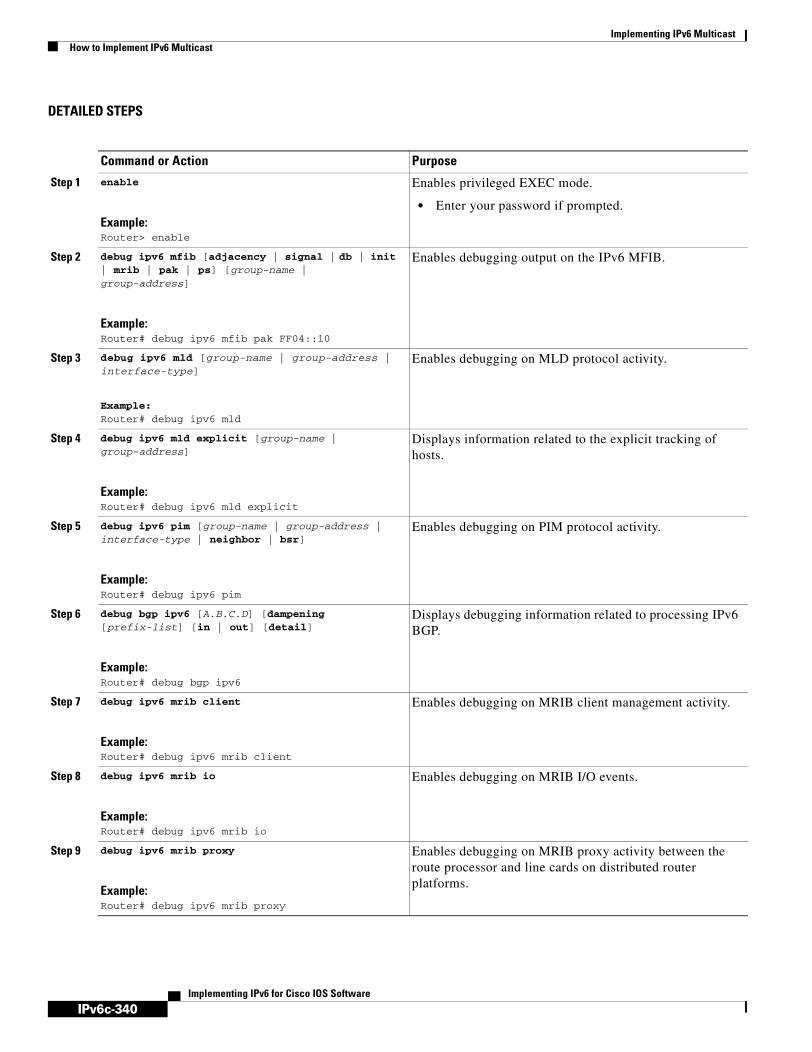
IPv6c-340
Implementing IPv6 MulticastHow to Implement IPv6 Multicast
Implementing IPv6 for Cisco IOS Software
DETAILED STEPS
Command or Action Purpose
Step 1 enable
Example:Router> enable
Enables privileged EXEC mode.
• Enter your password if prompted.
Step 2 debug ipv6 mfib [adjacency | signal | db | init | mrib | pak | ps] [group-name | group-address]
Example:Router# debug ipv6 mfib pak FF04::10
Enables debugging output on the IPv6 MFIB.
Step 3 debug ipv6 mld [group-name | group-address | interface-type]
Example:Router# debug ipv6 mld
Enables debugging on MLD protocol activity.
Step 4 debug ipv6 mld explicit [group-name | group-address]
Example:Router# debug ipv6 mld explicit
Displays information related to the explicit tracking of hosts.
Step 5 debug ipv6 pim [group-name | group-address | interface-type | neighbor | bsr]
Example:Router# debug ipv6 pim
Enables debugging on PIM protocol activity.
Step 6 debug bgp ipv6 [A.B.C.D] [dampening [prefix-list] [in | out] [detail]
Example:Router# debug bgp ipv6
Displays debugging information related to processing IPv6 BGP.
Step 7 debug ipv6 mrib client
Example:Router# debug ipv6 mrib client
Enables debugging on MRIB client management activity.
Step 8 debug ipv6 mrib io
Example:Router# debug ipv6 mrib io
Enables debugging on MRIB I/O events.
Step 9 debug ipv6 mrib proxy
Example:Router# debug ipv6 mrib proxy
Enables debugging on MRIB proxy activity between the route processor and line cards on distributed router platforms.
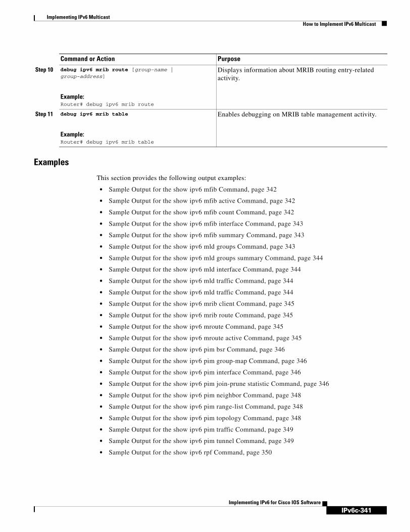
IPv6c-341
Implementing IPv6 MulticastHow to Implement IPv6 Multicast
Implementing IPv6 for Cisco IOS Software
Examples
This section provides the following output examples:
• Sample Output for the show ipv6 mfib Command, page 342
• Sample Output for the show ipv6 mfib active Command, page 342
• Sample Output for the show ipv6 mfib count Command, page 342
• Sample Output for the show ipv6 mfib interface Command, page 343
• Sample Output for the show ipv6 mfib summary Command, page 343
• Sample Output for the show ipv6 mld groups Command, page 343
• Sample Output for the show ipv6 mld groups summary Command, page 344
• Sample Output for the show ipv6 mld interface Command, page 344
• Sample Output for the show ipv6 mld traffic Command, page 344
• Sample Output for the show ipv6 mld traffic Command, page 344
• Sample Output for the show ipv6 mrib client Command, page 345
• Sample Output for the show ipv6 mrib route Command, page 345
• Sample Output for the show ipv6 mroute Command, page 345
• Sample Output for the show ipv6 mroute active Command, page 345
• Sample Output for the show ipv6 pim bsr Command, page 346
• Sample Output for the show ipv6 pim group-map Command, page 346
• Sample Output for the show ipv6 pim interface Command, page 346
• Sample Output for the show ipv6 pim join-prune statistic Command, page 346
• Sample Output for the show ipv6 pim neighbor Command, page 348
• Sample Output for the show ipv6 pim range-list Command, page 348
• Sample Output for the show ipv6 pim topology Command, page 348
• Sample Output for the show ipv6 pim traffic Command, page 349
• Sample Output for the show ipv6 pim tunnel Command, page 349
• Sample Output for the show ipv6 rpf Command, page 350
Step 10 debug ipv6 mrib route [group-name | group-address]
Example:Router# debug ipv6 mrib route
Displays information about MRIB routing entry-related activity.
Step 11 debug ipv6 mrib table
Example:Router# debug ipv6 mrib table
Enables debugging on MRIB table management activity.
Command or Action Purpose

IPv6c-342
Implementing IPv6 MulticastHow to Implement IPv6 Multicast
Implementing IPv6 for Cisco IOS Software
Sample Output for the show ipv6 mfib Command
The following example displays the forwarding entries and interfaces in the MFIB. The router is configured for fast switching, and it has a receiver joined to FF05::1 on Ethernet1/1 and a source (2001:0DB8:1:1:20) sending on Ethernet1/2:
Router# show ipv6 mfib
IP Multicast Forwarding Information BaseEntry Flags: C - Directly Connected, S - Signal, IA - Inherit A flag, AR - Activity Required, D - DropForwarding Counts: Pkt Count/Pkts per second/Avg Pkt Size/Kbits per secondOther counts: Total/RPF failed/Other dropsInterface Flags: A - Accept, F - Forward, NS - Negate Signalling IC - Internal Copy, NP - Not platform switched SP - Signal PresentInterface Counts: FS Pkt Count/PS Pkt Count(*,FF00::/8) Flags: C Forwarding: 0/0/0/0, Other: 0/0/0 Tunnel0 Flags: NS(*,FF00::/15) Flags: D Forwarding: 0/0/0/0, Other: 0/0/0(*,FF05::1) Flags: C Forwarding: 2/0/100/0, Other: 0/0/0 Tunnel0 Flags: A NS Ethernet1/1 Flags: F NS Pkts: 0/2(2001:0DB8:1:1:200,FF05::1) Flags: Forwarding: 5/0/100/0, Other: 0/0/0 Ethernet1/2 Flags: A Ethernet1/1 Flags: F NS Pkts: 3/2(*,FF10::/15) Flags: D Forwarding: 0/0/0/0, Other: 0/0/0
Sample Output for the show ipv6 mfib active Command
The following example displays statistics on the rate at which active IP multicast sources are sending information. The router is switching traffic from 2001:0DB8:1:1:200 to FF05::1:
Router# show ipv6 mfib active
Active IPv6 Multicast Sources - sending >= 4 kbpsGroup: FF05::1 Source: 2001:0DB8:1:1:200 Rate: 20 pps/16 kbps(1sec), 0 kbps(last 128 sec)
Sample Output for the show ipv6 mfib count Command
The following example displays statistics from the MFIB about the group and source. The router is switching traffic from 2001:0DB8:1:1:200 to FF05::1:
Router# show ipv6 mfib count
IP Multicast Statistics54 routes, 7 groups, 0.14 average sources per groupForwarding Counts: Pkt Count/Pkts per second/Avg Pkt Size/Kilobits per secondOther counts: Total/RPF failed/Other drops(OIF-null, rate-limit etc)Group: FF00::/8 RP-tree: Forwarding: 0/0/0/0, Other: 0/0/0Group: FF00::/15 RP-tree: Forwarding: 0/0/0/0, Other: 0/0/0Group: FF05::1 RP-tree: Forwarding: 2/0/100/0, Other: 0/0/0 Source: 10::1:1:200, Forwarding: 367/10/100/7, Other: 0/0/0
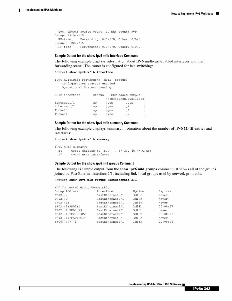
IPv6c-343
Implementing IPv6 MulticastHow to Implement IPv6 Multicast
Implementing IPv6 for Cisco IOS Software
Tot. shown: Source count: 1, pkt count: 369Group: FF10::/15 RP-tree: Forwarding: 0/0/0/0, Other: 0/0/0Group: FF20::/15 RP-tree: Forwarding: 0/0/0/0, Other: 0/0/0
Sample Output for the show ipv6 mfib interface Command
The following example displays information about IPv6 multicast-enabled interfaces and their forwarding status. The router is configured for fast switching:
Router# show ipv6 mfib interface
IPv6 Multicast Forwarding (MFIB) status: Configuration Status: enabled Operational Status: running
MFIB interface status CEF-based output [configured,available]Ethernet1/1 up [yes ,yes ]Ethernet1/2 up [yes ,? ]Tunnel0 up [yes ,? ]Tunnel1 up [yes ,? ]
Sample Output for the show ipv6 mfib summary Command
The following example displays summary information about the number of IPv6 MFIB entries and interfaces:
Router# show ipv6 mfib summary
IPv6 MFIB summary: 54 total entries [1 (S,G), 7 (*,G), 46 (*,G/m)] 17 total MFIB interfaces
Sample Output for the show ipv6 mld groups Command
The following is sample output from the show ipv6 mld groups command. It shows all of the groups joined by Fast Ethernet interface 2/1, including link-local groups used by network protocols.
Router# show ipv6 mld groups FastEthernet 2/1
MLD Connected Group MembershipGroup Address Interface Uptime ExpiresFF02::2 FastEthernet2/1 3d18h neverFF02::D FastEthernet2/1 3d18h neverFF02::16 FastEthernet2/1 3d18h neverFF02::1:FF00:1 FastEthernet2/1 3d18h 00:00:27FF02::1:FF00:79 FastEthernet2/1 3d18h neverFF02::1:FF23:83C2 FastEthernet2/1 3d18h 00:00:22FF02::1:FFAF:2C39 FastEthernet2/1 3d18h neverFF06:7777::1 FastEthernet2/1 3d18h 00:00:26

IPv6c-344
Implementing IPv6 MulticastHow to Implement IPv6 Multicast
Implementing IPv6 for Cisco IOS Software
Sample Output for the show ipv6 mld groups summary Command
The following is sample output from the show ipv6 mld groups summary command:
Router# show ipv6 mld groups summary
MLD Route Summary No. of (*,G) routes = 5 No. of (S,G) routes = 0
Sample Output for the show ipv6 mld interface Command
The following is sample output from the show ipv6 mld interface command for Fast Ethernet interface 2/1:
Router# show ipv6 mld interface FastEthernet 2/1
FastEthernet2/1 is up, line protocol is upInternet address is FE80::205:5FFF:FEAF:2C39/10MLD is enabled in interfaceCurrent MLD version is 2MLD query interval is 125 secondsMLD querier timeout is 255 secondsMLD max query response time is 10 seconds Last member query response interval is 1 secondsMLD activity: 25 joins, 17 leavesMLD querying router is FE80::205:5FFF:FEAF:2C39 (this system)
Sample Output for the show ipv6 mld ssm-map Command
The following examples show SSM mapping for the source address 2001:0DB8::1:
Router# show ipv6 mld ssm-map 2001:0DB8::1
Group address : 2001:0DB8::1 Group mode ssm : TRUE Database : STATIC Source list : 2001:0DB8::2
2001:0DB8::3
Router# show ipv6 mld ssm-map 2001:0DB8::2
Group address : 2001:0DB8::2 Group mode ssm : TRUE Database : DNS Source list : 2001:0DB8::3
2001:0DB8::1
Sample Output for the show ipv6 mld traffic Command
The following example displays the MLD protocol messages received and sent.
Router# show ipv6 mld traffic
MLD Traffic CountersElapsed time since counters cleared:00:00:21
Received SentValid MLD Packets 3 1 Queries 1 0 Reports 2 1 Leaves 0 0 Mtrace packets 0 0
Errors:Malformed Packets 0

IPv6c-345
Implementing IPv6 MulticastHow to Implement IPv6 Multicast
Implementing IPv6 for Cisco IOS Software
Bad Checksums 0 Martian source 0 Packets Received on MLD-disabled Interface 0
Sample Output for the show ipv6 mrib client Command
The following is sample output from the show ipv6 mrib client command:
Router# show ipv6 mrib client
IP MRIB client-connectionsigmp:145 (connection id 0)pim:146 (connection id 1)mfib ipv6:3 (connection id 2)slot 3 mfib ipv6 rp agent:16 (connection id 3)slot 1 mfib ipv6 rp agent:16 (connection id 4)slot 0 mfib ipv6 rp agent:16 (connection id 5)slot 4 mfib ipv6 rp agent:16 (connection id 6)slot 2 mfib ipv6 rp agent:16 (connection id 7)
Sample Output for the show ipv6 mrib route Command
The following is sample output from the show ipv6 mrib route command using the summary keyword:
Router# show ipv6 mrib route summary
MRIB Route-DB Summary No. of (*,G) routes = 52 No. of (S,G) routes = 0 No. of Route x Interfaces (RxI) = 10
Sample Output for the show ipv6 mroute Command
Using the show ipv6 mroute command is a good way to dynamically verify that multicast IPv6 data is flowing. The following is sample output from the show ipv6 mroute command:
Router# show ipv6 mroute ff07::1
Multicast Routing TableFlags:D - Dense, S - Sparse, B - Bidir Group, s - SSM Group, C - Connected, L - Local, I - Received Source Specific Host Report, P - Pruned, R - RP-bit set, F - Register flag, T - SPT-bit set, J - Join SPT Timers:Uptime/ExpiresInterface state:Interface, State
(*, FF07::1), 00:04:45/00:02:47, RP 2001:0DB8:6::6, flags:S Incoming interface:Tunnel5 RPF nbr:6:6:6::6 Outgoing interface list: POS4/0, Forward, 00:04:45/00:02:47
(2001:0DB8:999::99, FF07::1), 00:02:06/00:01:23, flags:SFT Incoming interface:POS1/0 RPF nbr:2001:0DB8:999::99 Outgoing interface list: POS4/0, Forward, 00:02:06/00:03:27
Sample Output for the show ipv6 mroute active Command
The following is sample output from the show ipv6 mroute active command:
Router# show ipv6 mroute active
Active IPv6 Multicast Sources - sending >= 4 kbpsGroup:FF05::1

IPv6c-346
Implementing IPv6 MulticastHow to Implement IPv6 Multicast
Implementing IPv6 for Cisco IOS Software
Source:2001:0DB8:1:1:1 Rate:11 pps/8 kbps(1sec), 8 kbps(last 8 sec)
Sample Output for the show ipv6 pim bsr Command
The following example displays BSM election information:
Router# show ipv6 pim bsr election
PIMv2 BSR informationBSR Election InformationScope Range List: ff00::/8This system is the Bootstrap Router (BSR)BSR Address: 2001:0DB8:1:1:4Uptime: 00:11:55, BSR Priority: 0, Hash mask length: 126RPF: FE80::A8BB:CCFF:FE03:C400,Ethernet0/0BS Timer: 00:00:07This system is candidate BSRCandidate BSR address: 2001:0DB8:1:1:4, priority: 0, hash mask length: 126
Sample Output for the show ipv6 pim group-map Command
The following is sample output from the show ipv6 pim group-map command:
Router# show ipv6 pim group-map
FF33::/32* SSM Info source:Static Uptime:00:08:32, Groups:0 FF34::/32* SSM Info source:Static Uptime:00:09:42, Groups:0
Sample Output for the show ipv6 pim interface Command
The following is sample output from the show ipv6 pim interface command using the state-on keyword:
Router# show ipv6 pim interface state-on
Interface PIM Nbr Hello DR Count Intvl Prior
Ethernet0 on 0 30 1 Address:FE80::208:20FF:FE08:D7FF DR :this systemPOS1/0 on 0 30 1 Address:FE80::208:20FF:FE08:D554 DR :this systemPOS4/0 on 1 30 1 Address:FE80::208:20FF:FE08:D554 DR :FE80::250:E2FF:FE8B:4C80POS4/1 on 0 30 1 Address:FE80::208:20FF:FE08:D554 DR :this systemLoopback0 on 0 30 1 Address:FE80::208:20FF:FE08:D554 DR :this system
Sample Output for the show ipv6 pim join-prune statistic Command
The following example provides the join/prune aggregation on Ethernet interface 0/0/0:
Router# show ipv6 pim join-prune statistic Ethernet0/0/0

IPv6c-347
Implementing IPv6 MulticastHow to Implement IPv6 Multicast
Implementing IPv6 for Cisco IOS Software
PIM Average Join/Prune Aggregation for last (1K/10K/50K) packetsInterface Transmitted Received
Ethernet0/0/0 0 / 0 / 0 1 / 0 / 0
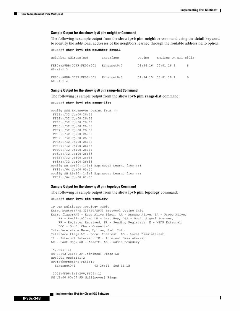
IPv6c-348
Implementing IPv6 MulticastHow to Implement IPv6 Multicast
Implementing IPv6 for Cisco IOS Software
Sample Output for the show ipv6 pim neighbor Command
The following is sample output from the show ipv6 pim neighbor command using the detail keyword to identify the additional addresses of the neighbors learned through the routable address hello option:
Router# show ipv6 pim neighbor detail
Neighbor Address(es) Interface Uptime Expires DR pri Bidir
FE80::A8BB:CCFF:FE00:401 Ethernet0/0 01:34:16 00:01:16 1 B60::1:1:3
FE80::A8BB:CCFF:FE00:501 Ethernet0/0 01:34:15 00:01:18 1 B60::1:1:4
Sample Output for the show ipv6 pim range-list Command
The following is sample output from the show ipv6 pim range-list command:
Router# show ipv6 pim range-list
config SSM Exp:never Learnt from ::: FF33::/32 Up:00:26:33 FF34::/32 Up:00:26:33 FF35::/32 Up:00:26:33 FF36::/32 Up:00:26:33 FF37::/32 Up:00:26:33 FF38::/32 Up:00:26:33 FF39::/32 Up:00:26:33 FF3A::/32 Up:00:26:33 FF3B::/32 Up:00:26:33 FF3C::/32 Up:00:26:33 FF3D::/32 Up:00:26:33 FF3E::/32 Up:00:26:33 FF3F::/32 Up:00:26:33config SM RP:40::1:1:1 Exp:never Learnt from ::: FF13::/64 Up:00:03:50config SM RP:40::1:1:3 Exp:never Learnt from ::: FF09::/64 Up:00:03:50
Sample Output for the show ipv6 pim topology Command
The following is sample output from the show ipv6 pim topology command:
Router# show ipv6 pim topology
IP PIM Multicast Topology TableEntry state:(*/S,G)[RPT/SPT] Protocol Uptime InfoEntry flags:KAT - Keep Alive Timer, AA - Assume Alive, PA - Probe Alive, RA - Really Alive, LH - Last Hop, DSS - Don't Signal Sources, RR - Register Received, SR - Sending Registers, E - MSDP External, DCC - Don't Check ConnectedInterface state:Name, Uptime, Fwd, InfoInterface flags:LI - Local Interest, LD - Local Dissinterest,II - Internal Interest, ID - Internal Dissinterest,LH - Last Hop, AS - Assert, AB - Admin Boundary
(*,FF05::1)SM UP:02:26:56 JP:Join(now) Flags:LH RP:2001:0DB8:1:1:2RPF:Ethernet1/1,FE81::1 Ethernet0/1 02:26:56 fwd LI LH
(2001:0DB8:1:1:200,FF05::1)SM UP:00:00:07 JP:Null(never) Flags:

IPv6c-349
Implementing IPv6 MulticastHow to Implement IPv6 Multicast
Implementing IPv6 for Cisco IOS Software
RPF:Ethernet1/1,FE80::30:1:4 Ethernet1/1 00:00:07 off LI
Sample Output for the show ipv6 pim traffic Command
The following example shows the number of PIM protocol messages received and sent.
Router# show ipv6 pim traffic
PIM Traffic CountersElapsed time since counters cleared:00:05:29
Received SentValid PIM Packets 22 22 Hello 22 22 Join-Prune 0 0 Register 0 0 Register Stop 0 0 Assert 0 0 Bidir DF Election 0 0
Errors:Malformed Packets 0 Bad Checksums 0 Send Errors 0 Packet Sent on Loopback Errors 0 Packets Received on PIM-disabled Interface 0 Packets Received with Unknown PIM Version 0
Sample Output for the show ipv6 pim tunnel Command
The following is sample output from the show ipv6 pim tunnel command on the RP:
Router# show ipv6 pim tunnel
Tunnel0*Type :PIM EncapRP :100::1Source:100::1
Tunnel0*Type :PIM DecapRP :100::1Source: -
The following is sample output from the show ipv6 pim tunnel command on a non-RP:
Router# show ipv6 pim tunnel
Tunnel0* Type :PIM Encap RP :100::1 Source:2001::1:1:1

IPv6c-350
Implementing IPv6 MulticastConfiguration Examples for IPv6 Multicast
Implementing IPv6 for Cisco IOS Software
Sample Output for the show ipv6 rpf Command
The following example displays RPF information for the unicast host with the IPv6 address of 2001:0DB8:1:1:2:
Router# show ipv6 rpf 2001:0DB8:1:1:2
RPF information for 2001:0DB8:1:1:2 RPF interface:Ethernet3/2 RPF neighbor:FE80::40:1:3 RPF route/mask:20::/64 RPF type:Unicast RPF recursion count:0 Metric preference:110 Metric:30
Configuration Examples for IPv6 MulticastThis section provides the following configuration examples:
• Enabling IPv6 Multicast Routing: Example, page 350
• Configuring PIM: Examples, page 351
• Configuring PIM Options: Example, page 351
• Configuring the MLD Protocol: Examples, page 351
• Configuring Explicit Tracking of Receivers: Example, page 351
• Configuring Mroutes: Example, page 352
• Configuring an IPv6 Multiprotocol BGP Peer Group: Example, page 352
• Advertising Routes into IPv6 Multiprotocol BGP: Example, page 352
• Redistributing Prefixes into IPv6 Multiprotocol BGP: Example, page 352
• Generating Translate Updates for IPv6 Multicast BGP: Example, page 352
• Disabling Embedded RP Support in IPv6 PIM: Example, page 353
• Turning Off IPv6 PIM on a Specified Interface: Example, page 353
• Disabling MLD Router-Side Processing: Example, page 353
• Disabling and Reenabling MFIB: Example, page 353
Enabling IPv6 Multicast Routing: ExampleThe following example enables multicast routing on all interfaces. Entering this command also enables multicast forwarding for PIM and MLD on all enabled interfaces of the router.
Router> enableRouter# configure terminalRouter(config)# ipv6 multicast-routing
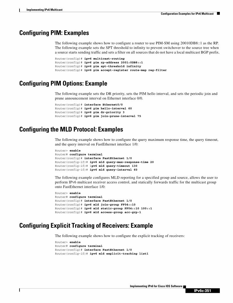
IPv6c-351
Implementing IPv6 MulticastConfiguration Examples for IPv6 Multicast
Implementing IPv6 for Cisco IOS Software
Configuring PIM: ExamplesThe following example shows how to configure a router to use PIM-SM using 20010DB8::1 as the RP. The following example sets the SPT threshold to infinity to prevent switchover to the source tree when a source starts sending traffic and sets a filter on all sources that do not have a local multicast BGP prefix.
Router(config)# ipv6 multicast-routingRouter(config)# ipv6 pim rp-address 2001:0DB8::1Router(config)# ipv6 pim spt-threshold infinityRouter(config)# ipv6 pim accept-register route-map reg-filter
Configuring PIM Options: ExampleThe following example sets the DR priority, sets the PIM hello interval, and sets the periodic join and prune announcement interval on Ethernet interface 0/0.
Router(config)# interface Ethernet0/0Router(config)# ipv6 pim hello-interval 60Router(config)# ipv6 pim dr-priority 3Router(config)# ipv6 pim join-prune-interval 75
Configuring the MLD Protocol: ExamplesThe following example shows how to configure the query maximum response time, the query timeout, and the query interval on FastEthernet interface 1/0:
Router> enableRouter# configure terminalRouter(config)# interface FastEthernet 1/0Router(config-if)# ipv6 mld query-max-response-time 20Router(config-if)# ipv6 mld query-timeout 130Router(config-if)# ipv6 mld query-interval 60
The following example configures MLD reporting for a specified group and source, allows the user to perform IPv6 multicast receiver access control, and statically forwards traffic for the multicast group onto FastEthernet interface 1/0:
Router> enableRouter# configure terminalRouter(config)# interface FastEthernet 1/0Router(config)# ipv6 mld join-group FF04::10Router(config)# ipv6 mld static-group FF04::10 100::1Router(config)# ipv6 mld access-group acc-grp-1
Configuring Explicit Tracking of Receivers: ExampleThe following example shows how to configure the explicit tracking of receivers:
Router> enableRouter# configure terminalRouter(config)# interface FastEthernet 1/0Router(config-if)# ipv6 mld explicit-tracking list1

IPv6c-352
Implementing IPv6 MulticastConfiguration Examples for IPv6 Multicast
Implementing IPv6 for Cisco IOS Software
Configuring Mroutes: ExampleThe following example shows how to configure a static multicast route to be used for multicast RPF selection only.
Router> enableRouter# configure terminalRouter(config)# ipv6 route 2001:0DB8::/64 7::7 100 multicast
Configuring an IPv6 Multiprotocol BGP Peer Group: ExampleThe following example configures the IPv6 multiprotocol BGP peer group named group1:
router bgp 65000no bgp default ipv4-unicastneighbor group1 peer-groupneighbor 2001:0DB8:0:CC00::1 remote-as 64600
address-family ipv6 multicast neighbor 3FFE:C00:0:1:A8BB:CCFF:FE00:8200 activate no auto-summary no synchronization exit-address-family
Advertising Routes into IPv6 Multiprotocol BGP: ExampleThe following example injects the IPv6 network 2001:0DB8::/24 into the IPv6 multicast database of the local router. (BGP checks that a route for the network exists in the IPv6 multicast database of the local router before advertising the network.)
router bgp 65000no bgp default ipv4-unicast
address-family ipv6 multicast network 2001:0DB8::/24
Redistributing Prefixes into IPv6 Multiprotocol BGP: ExampleThe following example redistributes BGP routes into the IPv6 multicast database of the local router:
router bgp 64900no bgp default ipv4-unicast
address-family ipv6 multicastredistribute BGP
Generating Translate Updates for IPv6 Multicast BGP: ExampleThe following example shows how to generate IPv6 multicast BGP updates that correspond to unicast IPv6 updates.
router bgp 64900no bgp default ipv4-unicast
address-family ipv6 multicastneighbor 2001:0DB8:7000::2 translate-update ipv6 multicast

IPv6c-353
Implementing IPv6 MulticastAdditional References
Implementing IPv6 for Cisco IOS Software
Disabling Embedded RP Support in IPv6 PIM: ExampleThe following example disables embedded RP support on IPv6 PIM:
Router(config)# ipv6 multicast-routingRouter(config)# no ipv6 pim rp embedded
Turning Off IPv6 PIM on a Specified Interface: ExampleThe following example turns off IPv6 PIM on FastEthernet interface 1/0:
Router(config)# ipv6 multicast-routingRouter(config)# interface FastEthernet 1/0Router(config)# no ipv6 pim
Disabling MLD Router-Side Processing: ExampleThe following example turns off MLD router-side processing on FastEthernet interface 1/0:
Router> enableRouter# configure terminalRouter(config)# interface FastEthernet 1/0Router(config-if)# no ipv6 mld router
Disabling and Reenabling MFIB: ExampleMulticast forwarding is automatically enabled when IPv6 multicast routing is enabled; however, a user may want to disable multicast forwarding on the router. The following example shows how to disable multicast forwarding on the router and, if desired, reenable multicast forwarding on the router. The example also shows how to disable MFIB interrupt-level IPv6 multicast forwarding of outgoing packets on FastEthernet interface 1/0:
Router> enableRouter# configure terminalRouter(config) no ipv6 mfibRouter(config) ipv6 mfib-mode centralized-onlyRouter(config) interface FastEthernet 1/0Router(config-if) no ipv6 mfib fast
Additional ReferencesSee the following sections for additional information related to IPv6 multicast.
Related Documents
Related Topic Document Title
IPv6 multicast addresses Implementing Basic Connectivity for IPv6
IPv6 supported feature list Start Here: Cisco IOS Software Release Specifics for IPv6 Features
Multicast BGP for IPv6 Implementing Multiprotocol BGP for IPv6

IPv6c-354
Implementing IPv6 MulticastAdditional References
Implementing IPv6 for Cisco IOS Software
Standards and Drafts
IPv6 static routes Implementing Static Routes for IPv6
IPv6 tunnels Implementing Tunneling for IPv6
Platform-specific information for Cisco 12000 series Internet Routers
12.0(26)S release notes, New Software Features in Cisco IOS Release 12.0(26)S
IPv6 commands: complete command syntax, command mode, defaults, usage guidelines, and examples
IPv6 for Cisco IOS Command Reference
IPv4 configuration and command reference information
Cisco IOS IP Configuration Guide, Release 12.4Cisco IOS IP Command Reference, Volume 3 of 4: Multicast, Release 12.4
Standards Title
draft-ietf-pim-sm-v2-new Protocol Independent Multicast - Sparse Mode PIM-SM): Protocol Specification (Revised), March 6, 2003
draft-savola-mboned-mcast-rpaddr Embedding the Address of RP in IPv6 Multicast Address, May 23, 2003
draft-suz-pim-upstream-detection PIM Upstream Detection Among Multiple Addresses, February 2003
draft-ietf-pim-bidir-05 Bi-directional Protocol Independent Multicast (BIDIR-PIM), June 20, 2003
draft-ietf-pim-sm-bsr-03.txt Bootstrap Router (BSR) Mechanism for PIM Sparse Mode, February 25, 2003
Related Topic Document Title

IPv6c-355
Implementing IPv6 MulticastAdditional References
Implementing IPv6 for Cisco IOS Software
MIBs
RFCs
Technical Assistance
MIBs MIBs Link
No new or modified MIBs are supported by this feature, and support for existing MIBs has not been modified by this feature.
To locate and download MIBs for selected platforms, Cisco IOS releases, and feature sets, use Cisco MIB Locator found at the following URL:
http://www.cisco.com/go/mibs
RFCs Title
RFC 2373 IP Version 6 Addressing Architecture
RFC 2460 Internet Protocol, Version 6 (IPv6) Specification
RFC 2461 Neighbor Discovery for IP version 6 (IPv6)
RFC 2462 IPv6 Stateless Address Autoconfiguration
RFC 3576 Change of Authorization
RFC 3590 Source Address Selection for the Multicast Listener Discovery (MLD) Protocol
RFC 3810 Multicast Listener Discovery Version 2 (MLDv2) for IPv6
RFC 4007 IPv6 Scoped Address Architecture
Description Link
The Cisco Technical Support website contains thousands of pages of searchable technical content, including links to products, technologies, solutions, technical tips, and tools. Registered Cisco.com users can log in from this page to access even more content.
http://www.cisco.com/techsupport

IPv6c-356
Implementing IPv6 MulticastAdditional References
Implementing IPv6 for Cisco IOS Software

IPv6c-357Implementing IPv6 for Cisco IOS Software
Managing Cisco IOS Applications over IPv6
This document describes the concepts and commands used to enable access to an IPv6 router. The copy, ping, telnet, and traceroute commands have been modified in the Cisco IOS Release 12.2(13)T to provide IPv6 management capability. Secure Shell (SSH) has been enhanced to provide support for IPv6 addresses that enable a Cisco router to accept and establish secure, encrypted connections with remote IPv6 nodes over an IPv6 transport.
Finding Support Information for Platforms and Cisco IOS Software Images
Use Cisco Feature Navigator to find information about platform support and Cisco IOS software image support. Access Cisco Feature Navigator at http://www.cisco.com/go/fn. You must have an account on Cisco.com. If you do not have an account or have forgotten your username or password, click Cancel at the login dialog box and follow the instructions that appear.
Contents• Prerequisites for Managing Cisco IOS Applications over IPv6, page 357
• Information About Managing Cisco IOS Applications over IPv6, page 358
• How to Manage Cisco IOS Applications over IPv6, page 360
• Configuration Examples for Managing Cisco IOS Applications over IPv6, page 366
• Where to Go Next, page 369
• Additional References, page 369
Prerequisites for Managing Cisco IOS Applications over IPv6• This document assumes that you are familiar with IPv4. Refer to the publications referenced in the
“Additional References” section for IPv4 configuration and command reference information.
• By default, IPv6 routing is disabled in the Cisco IOS software. To enable IPv6 routing, you must first enable the forwarding of IPv6 traffic globally on the router and then you must assign IPv6 addresses to individual interfaces in the router. At least one interface must have IPv6 configured.
• To enable Telnet access to a router, you must create a vty interface and password.
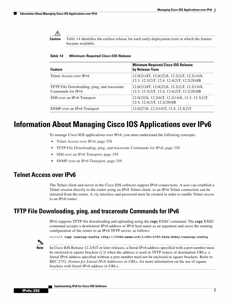
IPv6c-358
Managing Cisco IOS Applications over IPv6Information About Managing Cisco IOS Applications over IPv6
Implementing IPv6 for Cisco IOS Software
Caution Table 14 identifies the earliest release for each early-deployment train in which the feature became available.
Information About Managing Cisco IOS Applications over IPv6To manage Cisco IOS applications over IPv6, you must understand the following concepts:
• Telnet Access over IPv6, page 358
• TFTP File Downloading, ping, and traceroute Commands for IPv6, page 358
• SSH over an IPv6 Transport, page 359
• SNMP over an IPv6 Transport, page 359
Telnet Access over IPv6The Telnet client and server in the Cisco IOS software support IPv6 connections. A user can establish a Telnet session directly to the router using an IPv6 Telnet client, or an IPv6 Telnet connection can be initiated from the router. A vty interface and password must be created in order to enable Telnet access to an IPv6 router.
TFTP File Downloading, ping, and traceroute Commands for IPv6IPv6 supports TFTP file downloading and uploading using the copy EXEC command. The copy EXEC command accepts a destination IPv6 address or IPv6 host name as an argument and saves the running configuration of the router to an IPv6 TFTP server, as follows:
Router# copy running-config tftp://[3ffe:xxxx:c18:1:290:27ff:fe3a:9e9a]/running-config
Note In Cisco IOS Release 12.2(8)T or later releases, a literal IPv6 address specified with a port number must be enclosed in square brackets ([ ]) when the address is used in TFTP source or destination URLs; a literal IPv6 address specified without a port number need not be enclosed in square brackets. Refer to RFC 2732, Format for Literal IPv6 Addresses in URLs, for more information on the use of square brackets with literal IPv6 address in URLs.
Table 14 Minimum Required Cisco IOS Release
FeatureMinimum Required Cisco IOS Release by Release Train
Telnet Access over IPv6 12.0(21)ST, 12.0(22)S, 12.2(2)T, 12.2(14)S, 12.3, 12.3(2)T, 12.4, 12.4(2)T, 12.2(28)SB
TFTP File Downloading, ping, and traceroute Commands for IPv6
12.0(21)ST, 12.0(22)S, 12.2(2)T, 12.2(14)S, 12.3, 12.3(2)T, 12.4, 12.4(2)T, 12.2(28)SB
SSH over an IPv6 Transport 12.0(22)S, 12.2(8)T, 12.2(14)S, 12.3, 12.3(2)T, 12.4, 12.4(2)T, 12.2(28)SB
SNMP over an IPv6 Transport 12.0(27)S, 12.3(14)T, 12.4, 12.4(2)T

IPv6c-359
Managing Cisco IOS Applications over IPv6Information About Managing Cisco IOS Applications over IPv6
Implementing IPv6 for Cisco IOS Software
The ping EXEC command accepts a destination IPv6 address or IPv6 host name as an argument and sends Internet Control Message Protocol version 6 (ICMPv6) echo request messages to the specified destination. The ICMPv6 echo reply messages are reported on the console. Extended ping functionality is also supported in IPv6.
The traceroute EXEC command accepts a destination IPv6 address or IPv6 host name as an argument and will generate IPv6 traffic to report each IPv6 hop used to reach the destination address.
Refer to the IPv6 for Cisco IOS Command Reference document for information on IPv6 modifications to the copy, ping, telnet, and traceroute commands. These commands also appear in the Cisco IOS Configuration Fundamentals Command Reference. Refer to the Start Here: Cisco IOS Software Release Specifics for IPv6 Features document on Cisco.com for Cisco IOS software release specifics for supported IPv6 features.
SSH over an IPv6 TransportIn Cisco IOS Release 12.2(8)T or later releases or Cisco IOS Release 12.0(22)S or later releases, SSH in IPv6 functions the same and offers the same benefits as SSH in IPv4—the SSH Server feature enables an SSH client to make a secure, encrypted connection to a Cisco router and the SSH Client feature enables a Cisco router to make a secure, encrypted connection to another Cisco router or to any other device running an SSH server. IPv6 enhancements to SSH consist of support for IPv6 addresses that enable a Cisco router to accept and establish secure, encrypted connections with remote IPv6 nodes over an IPv6 transport.
The SSH over an IPv6 Transport feature has no specific configuration tasks. The ssh EXEC command can be used to start an encrypted session with a remote IPv4 or IPv6 networking device. After the SSH server is enabled using the ip ssh global configuration command, inbound IPv4 and IPv6 connections can be made to the local router.
Note The SSH client runs in user EXEC mode and has no specific configuration tasks or commands.
On Cisco.com, refer to the “Configuring Secure Shell” chapter in the Cisco IOS Security Configuration Guide for additional SSH configuration information. Refer to the “Secure Shell Commands” chapter in the Cisco IOS Security Command Reference for additional SSH command information.
SNMP over an IPv6 TransportSimple Network Management Protocol (SNMP) can be configured over IPv6 transport so that an IPv6 host can perform SNMP queries and receive SNMP notifications from a device running Cisco IOS IPv6. The SNMP agent and related MIBs have been enhanced to support IPv6 addressing.
The following MIBs are supported for IPv6:
• CISCO-CONFIG-COPY-MIB
• CISCO-CONFIG-MAN-MIB
• CISCO-DATA-COLLECTION-MIB
• CISCO-FLASH-MIB
• ENTITY-MIB
• NOTIFICATION-LOG-MIB
• SNMP-TARGET-MIB

IPv6c-360
Managing Cisco IOS Applications over IPv6How to Manage Cisco IOS Applications over IPv6
Implementing IPv6 for Cisco IOS Software
CISCO-CONFIG-COPY-MIB and CISCO-FLASH-MIB support IPv6 addressing when either TFTP, remote copy protocol (rcp), or FTP is used.
The following MIB has been added for the IPv6 over SNMP support feature:
• CISCO-SNMP-TARGET-EXT-MIB
The following MIBs have been modified for the IPv6 over SNMP support feature:
• CISCO-FLASH-MIB
• CISCO-CONFIG-MAN-MIB
• CISCO-CONFIG-COPY-MIB
Refer to Cisco IOS Configuration Fundamentals Configuration Guide for detailed information about SNMP, MIBs, and managing Cisco networks in Cisco IOS software.
How to Manage Cisco IOS Applications over IPv6This section contains the following procedures:
• Enabling Telnet Access to an IPv6 Router and Establishing a Telnet Session, page 360 (Optional)
• Enabling SSH on an IPv6 Router, page 362 (Optional)
• Disabling HTTP Access to an IPv6 Router, page 363 (Optional)
• Configuring an SNMP Notification Server over IPv6, page 364 (Optional)
Enabling Telnet Access to an IPv6 Router and Establishing a Telnet Session This task describes how to enable Telnet access to an IPv6 router and establish a Telnet session. Using either IPv4 or IPv6 transport, you can use Telnet to connect from a host to a router, from a router to a router, and from a router to a host.
Refer to the Implementing Basic Connectivity for IPv6 module for information on IPv6 addressing and enabling IPv6 routing. Refer to the Cisco IOS Security Command Reference, Release 12.4, for information on password configuration.
SUMMARY STEPS
1. enable
2. configure terminal
3. ipv6 host name [port] ipv6-address1 [ipv6-address2...ipv6-address4]
4. line [aux | console | tty | vty] line-number [ending-line-number]
5. password password
6. login [local | tacacs]
7. ipv6 access-class acl-name
8. telnet host [port] [keyword]

IPv6c-361
Managing Cisco IOS Applications over IPv6How to Manage Cisco IOS Applications over IPv6
Implementing IPv6 for Cisco IOS Software
DETAILED STEPS
What to Do Next
Proceed to the “Configuration Examples for Managing Cisco IOS Applications over IPv6” section.
Command or Action Purpose
Step 1 enable
Example:Router> enable
Enables privileged EXEC mode.
• Enter your password if prompted.
Step 2 configure terminal
Example:Router# configure terminal
Enters global configuration mode.
Step 3 ipv6 host name [port] ipv6-address1 [ipv6-address2...ipv6-address4]
Example:Router(config)# ipv6 host cisco-sj 2001:0DB8:20:1::12
Defines a static host name-to-address mapping in the host name cache.
Step 4 line [aux | console | tty | vty] line-number [ending-line-number]
Example:Router(config)# line vty 0 4
Works with the vty keyword to create a vty interface.
Step 5 password password
Example:Router(config)# password hostword
Creates a password that enables Telnet.
Step 6 login [local | tacacs]
Example:Router(config)# login tacacs
(Optional) Enables password checking at login.
Step 7 ipv6 access-class acl-name
Example:Router(config)# ipv6 access-list hostlist
(Optional) Adds an IPv6 access list to the line interface.
• Using this command restricts remote access to sessions that match the access list.
Step 8 telnet host [port] [keyword]
Example:Router(config)# telnet cisco-sj
Establishes a Telnet session from a router to a remote host using either the host name or the IPv6 address.
The Telnet session can be established to a router name or to an IPv6 address.

IPv6c-362
Managing Cisco IOS Applications over IPv6How to Manage Cisco IOS Applications over IPv6
Implementing IPv6 for Cisco IOS Software
Enabling SSH on an IPv6 RouterThis task describes how to enable SSH for use over an IPv6 transport. If you do not configure SSH parameters, then the default values will be used.
Prerequisites
Prior to configuring SSH over an IPv6 transport, ensure that the following conditions exist:
• An IPSec (Data Encryption Standard (DES) or 3DES) encryption software image from Cisco IOS Release 12.2(8)T or later releases or Cisco IOS Release 12.0(22)S or later releases is loaded on your router. IPv6 transport for the SSH server and SSH client requires an IPSec encryption software image. Refer to the “Loading and Maintaining System Images” chapter of Cisco IOS Configuration Fundamentals Configuration Guide, Release 12.4, for information on downloading a software image to your router.
• A host name and host domain are configured for your router. Refer to the “Mapping Host Names to IPv6 Addresses” section of the Implementing Basic Connectivity for IPv6 module for information on assigning host names to IPv6 addresses and specifying default domain names that can be used by both IPv4 and IPv6.
• A Rivest, Shamir, and Adelman (RSA) key pair, which automatically enables SSH, is generated for your router. Refer to the “Configuring Certification Authority Interoperability” chapter of Cisco IOS Security Configuration Guide, Release 12.4, for information on generating an RSA key pair.
Note RSA is the public key cryptographic system developed by Ron Rivest, Adi Shamir, and Leonard Adelman. RSA keys come in pairs: one public key and one private key.
• A user authentication mechanism for local or remote access is configured on your router. Refer to the “Restrictions” section of the Start Here: Cisco IOS Software Release Specifics for IPv6 Features document for authentication mechanism restrictions for SSH over an IPv6 transport.
Restrictions
The basic restrictions for SSH over an IPv4 transport listed in the “Configuring Secure Shell” chapter of Cisco IOS Security Configuration Guide, Release 12.4, apply to SSH over an IPv6 transport. In addition to the restrictions listed in that chapter, the use of locally stored usernames and passwords is the only user authentication mechanism supported by SSH over an IPv6 transport; the TACACS+ and RADIUS user authentication mechanisms are not supported over an IPv6 transport.
Note To authenticate SSH clients, configure TACACS+ or RADIUS over an IPv4 transport and then connect to an SSH server over an IPv6 transport.
SUMMARY STEPS
1. enable
2. configure terminal
3. ip ssh [timeout seconds | authentication-retries integer]
4. exit

IPv6c-363
Managing Cisco IOS Applications over IPv6How to Manage Cisco IOS Applications over IPv6
Implementing IPv6 for Cisco IOS Software
5. ssh [-l userid] [-c {des | 3des}] [-o numberofpasswordprompts n] [-p port-num] {ip-addr | hostname} [command]
DETAILED STEPS
What to Do Next
Proceed to the “Configuration Examples for Managing Cisco IOS Applications over IPv6” section.
Disabling HTTP Access to an IPv6 RouterHTTP access over IPv6 is automatically enabled if an HTTP server is enabled and the router has an IPv6 address. If the HTTP server is not required, it should be disabled as described in this section.
Command or Action Purpose
Step 1 enable
Example:Router> enable
Enables privileged EXEC mode.
• Enter your password if prompted.
Step 2 configure terminal
Example:Router# configure terminal
Enters global configuration mode.
Step 3 ip ssh [timeout seconds | authentication-retries integer]
Example:Router(config)# ip ssh timeout 100 authentication-retries 2
Configures SSH control variables on your router.
• You can specify the timeout in seconds, not to exceed 120 seconds. The default is 120. This setting applies to the SSH negotiation phase. Once the EXEC session starts, the standard timeouts configured for the vty apply.
By default, five vty lines are defined (0–4); therefore, five terminal sessions are possible. After the SSH executes a shell, the vty timeout starts. The vty timeout defaults to 10 minutes.
• You can also specify the number of authentication retries, not to exceed five authentication retries. The default is three.
Step 4 exit
Example:Router(config)# exit
Exits configuration mode, and returns the router to privileged EXEC mode.
Step 5 ssh [-l userid] [-c {des | 3des}] [-o numberofpasswordprompts n] [-p port-num] {ip-addr | hostname} [command]
Example:Router# ssh
Starts an encrypted session with a remote networking device.

IPv6c-364
Managing Cisco IOS Applications over IPv6How to Manage Cisco IOS Applications over IPv6
Implementing IPv6 for Cisco IOS Software
SUMMARY STEPS
1. enable
2. configure terminal
3. no ip http server
DETAILED STEPS
What to Do Next
Proceed to the “Configuration Examples for Managing Cisco IOS Applications over IPv6” section.
Configuring an SNMP Notification Server over IPv6Use an SNMP community string to define the relationship between the SNMP manager and the agent. The community string acts like a password to regulate access to the agent on the router. Optionally, you can specify one or more of the following characteristics associated with the string:
• An access list of IP addresses of the SNMP managers that are permitted to use the community string to gain access to the agent.
• A MIB view, which defines the subset of all MIB objects accessible to the given community.
• Read and write or read-only permission for the MIB objects accessible to the community.
You can configure one or more community strings. To remove a specific community string, use the no snmp-server community command.
The snmp-server host command specifies which hosts will receive SNMP notifications, and whether you want the notifications sent as traps or inform requests. The snmp-server enable traps command globally enables the production mechanism for the specified notification types (such as Border Gateway Protocol [BGP] traps, config traps, entity traps, and Hot Standby Router Protocol [HSRP] traps).
SUMMARY STEPS
1. enable
Command or Action Purpose
Step 1 enable
Example:Router> enable
Enables privileged EXEC mode.
• Enter your password if prompted.
Step 2 configure terminal
Example:Router# configure terminal
Enters global configuration mode.
Step 3 no ip http server
Example:Router(config)# no ip http server
Disables HTTP access.
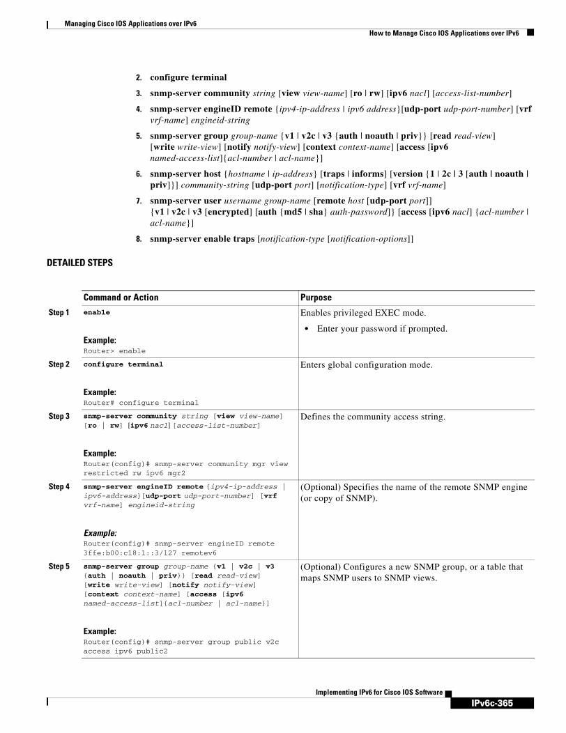
IPv6c-365
Managing Cisco IOS Applications over IPv6How to Manage Cisco IOS Applications over IPv6
Implementing IPv6 for Cisco IOS Software
2. configure terminal
3. snmp-server community string [view view-name] [ro | rw] [ipv6 nacl] [access-list-number]
4. snmp-server engineID remote {ipv4-ip-address | ipv6 address}[udp-port udp-port-number] [vrf vrf-name] engineid-string
5. snmp-server group group-name {v1 | v2c | v3 {auth | noauth | priv}} [read read-view] [write write-view] [notify notify-view] [context context-name] [access [ipv6 named-access-list]{acl-number | acl-name}]
6. snmp-server host {hostname | ip-address} [traps | informs] [version {1 | 2c | 3 [auth | noauth | priv]}] community-string [udp-port port] [notification-type] [vrf vrf-name]
7. snmp-server user username group-name [remote host [udp-port port]] {v1 | v2c | v3 [encrypted] [auth {md5 | sha} auth-password]} [access [ipv6 nacl] {acl-number | acl-name}]
8. snmp-server enable traps [notification-type [notification-options]]
DETAILED STEPS
Command or Action Purpose
Step 1 enable
Example:Router> enable
Enables privileged EXEC mode.
• Enter your password if prompted.
Step 2 configure terminal
Example:Router# configure terminal
Enters global configuration mode.
Step 3 snmp-server community string [view view-name] [ro | rw] [ipv6 nacl] [access-list-number]
Example:Router(config)# snmp-server community mgr view restricted rw ipv6 mgr2
Defines the community access string.
Step 4 snmp-server engineID remote {ipv4-ip-address | ipv6-address}[udp-port udp-port-number] [vrf vrf-name] engineid-string
Example:Router(config)# snmp-server engineID remote 3ffe:b00:c18:1::3/127 remotev6
(Optional) Specifies the name of the remote SNMP engine (or copy of SNMP).
Step 5 snmp-server group group-name {v1 | v2c | v3 {auth | noauth | priv}} [read read-view] [write write-view] [notify notify-view] [context context-name] [access [ipv6 named-access-list]{acl-number | acl-name}]
Example:Router(config)# snmp-server group public v2c access ipv6 public2
(Optional) Configures a new SNMP group, or a table that maps SNMP users to SNMP views.

IPv6c-366
Managing Cisco IOS Applications over IPv6Configuration Examples for Managing Cisco IOS Applications over IPv6
Implementing IPv6 for Cisco IOS Software
What to Do Next
Refer to the Cisco IOS Configuration Fundamentals Configuration Guide for more information about SNMP and MIBs.
Configuration Examples for Managing Cisco IOS Applications over IPv6
This section provides the following configuration examples:
• Enabling Telnet Access to an IPv6 Router Configuration: Examples, page 366
• Disabling HTTP Access to an IPv6 Router, page 363
• Configuring an SNMP Notification Server: Examples, page 368
Enabling Telnet Access to an IPv6 Router Configuration: ExamplesThe following examples provide information on how to enable Telnet and start a session to or from an IPv6 router. In the following example, the IPv6 address is specified as 2001:0db8:20:1::12, and the host name is specified as cisco-sj. The show host command is used to verify this information.
Router# configure terminal
Step 6 snmp-server host {hostname | ip-address} [traps | informs] [version {1 | 2c | 3 [auth | noauth | priv]}] community-string [udp-port port] [notification-type] [vrf vrf-name]
Example:Router(config)# snmp-server host host1.com 2c vrf trap-vrf
Specifies the recipient of an SNMP notification operation.
Specifies whether you want the SNMP notifications sent as traps or informs, the version of SNMP to use, the security level of the notifications (for SNMPv3), and the recipient (host) of the notifications.
Step 7 snmp-server user username group-name [remote host [udp-port port]] {v1 | v2c | v3 [encrypted] [auth {md5 | sha} auth-password]} [access [ipv6 nacl] {acl-number | acl-name}]
Example:Router(config)# snmp-server user user1 bldg1 remote 3ffe:b00:c18:1::3/127 v2c access ipv6 public2
(Optional) Configures a new user to an existing SNMP group.
Note You cannot configure a remote user for an address without first configuring the engine ID for that remote host. This is a restriction imposed in the design of these commands; if you try to configure the user before the host, you will receive a warning message and the command will not be executed
Step 8 snmp-server enable traps [notification-type [notification-options]]
Example:Router(config)# snmp-server enable traps bgp
Enables sending of traps or informs, and specifies the type of notifications to be sent.
• If a notification-type is not specified, all supported notification will be enabled on the router.
• To discover which notifications are available on your router, enter the snmp-server enable traps ? command.
Command or Action Purpose
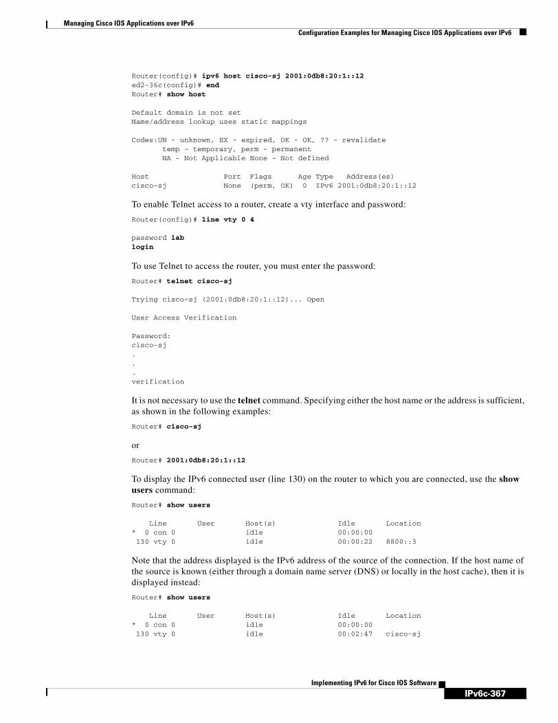
IPv6c-367
Managing Cisco IOS Applications over IPv6Configuration Examples for Managing Cisco IOS Applications over IPv6
Implementing IPv6 for Cisco IOS Software
Router(config)# ipv6 host cisco-sj 2001:0db8:20:1::12ed2-36c(config)# endRouter# show host
Default domain is not setName/address lookup uses static mappings
Codes:UN - unknown, EX - expired, OK - OK, ?? - revalidate temp - temporary, perm - permanent NA - Not Applicable None - Not defined
Host Port Flags Age Type Address(es)cisco-sj None (perm, OK) 0 IPv6 2001:0db8:20:1::12
To enable Telnet access to a router, create a vty interface and password:
Router(config)# line vty 0 4
password lablogin
To use Telnet to access the router, you must enter the password:
Router# telnet cisco-sj
Trying cisco-sj (2001:0db8:20:1::12)... Open
User Access Verification
Password:cisco-sj...verification
It is not necessary to use the telnet command. Specifying either the host name or the address is sufficient, as shown in the following examples:
Router# cisco-sj
or
Router# 2001:0db8:20:1::12
To display the IPv6 connected user (line 130) on the router to which you are connected, use the show users command:
Router# show users
Line User Host(s) Idle Location* 0 con 0 idle 00:00:00 130 vty 0 idle 00:00:22 8800::3
Note that the address displayed is the IPv6 address of the source of the connection. If the host name of the source is known (either through a domain name server (DNS) or locally in the host cache), then it is displayed instead:
Router# show users
Line User Host(s) Idle Location* 0 con 0 idle 00:00:00 130 vty 0 idle 00:02:47 cisco-sj

IPv6c-368
Managing Cisco IOS Applications over IPv6Configuration Examples for Managing Cisco IOS Applications over IPv6
Implementing IPv6 for Cisco IOS Software
If the user at the connecting router suspends the session with ^6x and then enters the show sessions command, the IPv6 connection is displayed:
Router# show sessions
Conn Host Address Byte Idle Conn Name* 1 cisco-sj 2001:0db8:20:1::12 0 0 cisco-sj
The Conn Name field shows the host name of the destination only if it is known. If it is not known, the output might look similar to the following:
Router# show sessions
Conn Host Address Byte Idle Conn Name* 1 2001:0db8:20:1::12 2001:0db8:20:1::12 0 0 2001:0db8:20:1::12
Disabling HTTP Access to the Router: ExampleIn the following example, the show running-config privileged EXEC command is used to show that HTTP access is disabled on the router:
Router# show running-config
Building configuration...!Current configuration : 1490 bytes!version 12.2!hostname Router!no ip http server!line con 0line aux 0line vty 0 4
Configuring an SNMP Notification Server: ExamplesThe following example permits any SNMP to access all objects with read-only permission using the community string named public. The router also will send BGP traps to the IPv4 host 172.16.1.111 and IPv6 host 3ffe:b00:c18:1::3/127 using SNMPv1 and to the host 172.16.1.27 using SNMPv2c. The community string named public is sent with the traps.
Router(config)# snmp-server community publicRouter(config)# snmp-server enable traps bgpRouter(config)# snmp-server host 172.16.1.27 version 2c publicRouter(config)# snmp-server host 172.16.1.111 version 1 publicRouter(config)# snmp-server host 3ffe:b00:c18:1::3/127 public
Associate an SNMP Server Group with Specified Views Example
In the following example, the SNMP context A is associated with the views in SNMPv2c group GROUP1 and the IPv6 named access list public2:
Router(config)# snmp-server context A Router(config)# snmp mib community-map commA context A target-list commAVpn Router(config)# snmp mib target list commAVpn vrf Customer_A Router(config)# snmp-server view viewA ciscoPingMIB includedRouter(config)# snmp-server view viewA ipForward included
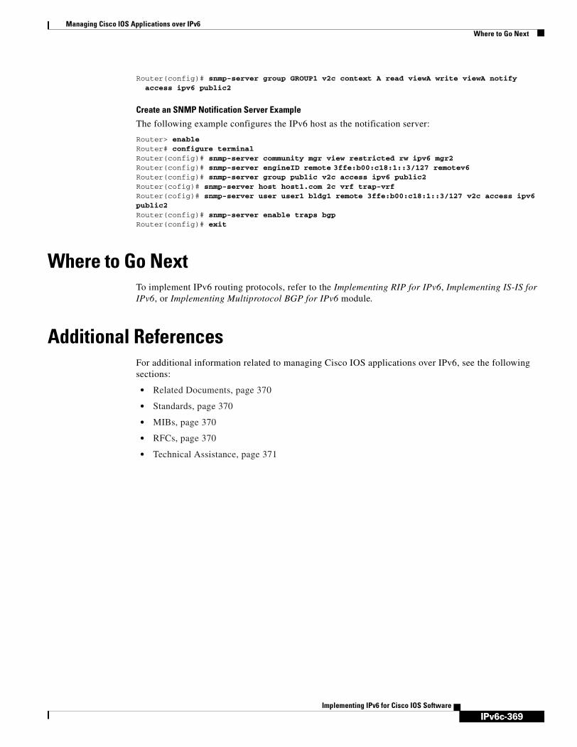
IPv6c-369
Managing Cisco IOS Applications over IPv6Where to Go Next
Implementing IPv6 for Cisco IOS Software
Router(config)# snmp-server group GROUP1 v2c context A read viewA write viewA notify access ipv6 public2
Create an SNMP Notification Server Example
The following example configures the IPv6 host as the notification server:
Router> enableRouter# configure terminalRouter(config)# snmp-server community mgr view restricted rw ipv6 mgr2Router(config)# snmp-server engineID remote 3ffe:b00:c18:1::3/127 remotev6Router(config)# snmp-server group public v2c access ipv6 public2Router(cofig)# snmp-server host host1.com 2c vrf trap-vrf Router(cofig)# snmp-server user user1 bldg1 remote 3ffe:b00:c18:1::3/127 v2c access ipv6 public2Router(config)# snmp-server enable traps bgpRouter(config)# exit
Where to Go NextTo implement IPv6 routing protocols, refer to the Implementing RIP for IPv6, Implementing IS-IS for IPv6, or Implementing Multiprotocol BGP for IPv6 module.
Additional ReferencesFor additional information related to managing Cisco IOS applications over IPv6, see the following sections:
• Related Documents, page 370
• Standards, page 370
• MIBs, page 370
• RFCs, page 370
• Technical Assistance, page 371

IPv6c-370
Managing Cisco IOS Applications over IPv6Additional References
Implementing IPv6 for Cisco IOS Software
Related Documents
Standards
MIBs
RFCs
Related Topic Document Title
tftp, ping, telnet, and traceroute command information
Cisco IOS Configuration Fundamentals Command Reference, Release 12.4
Cisco IOS Terminal Service Command Reference, Release 12.4
SSH configuration information Cisco IOS Security Command Reference, Release 12.4
IPv6 supported features Start Here: Cisco IOS Software Release Specifics for IPv6 Features
Basic IPv6 configuration tasks Implementing Basic Connectivity for IPv6
IPv6 commands: complete command syntax, command mode, defaults, usage guidelines, and examples
IPv6 for Cisco IOS Command Reference
IPv4 configuration and command reference information
Cisco IOS Release 12.4 Configuration Guides and Command References
Standards Title
No new or modified standards are supported by this feature, and support for existing standards has not been modified by this feature.
—
MIBs MIBs Link
• CISCO-CONFIG-COPY-MIB
• CISCO-DATA-COLLECTION-MIB
• CISCO-FLASH-MIB
• ENTITY-MIB
• NOTIFICATION-LOG-MIB
• SNMP-TARGET-MIB
• CISCO-SNMP-TARGET-EXT-MIB
To locate and download MIBs for selected platforms, Cisco IOS releases, and feature sets, use Cisco MIB Locator found at the following URL:
http://www.cisco.com/go/mibs
RFCs Title
RFC 2732 Format for Literal IPv6 Addresses in URLs
IPv6c-371
Managing Cisco IOS Applications over IPv6Additional References
Implementing IPv6 for Cisco IOS Software
Technical Assistance
Description Link
The Cisco Technical Support website contains thousands of pages of searchable technical content, including links to products, technologies, solutions, technical tips, and tools. Registered Cisco.com users can log in from this page to access even more content.
http://www.cisco.com/techsupport

IPv6c-372
Managing Cisco IOS Applications over IPv6Additional References
Implementing IPv6 for Cisco IOS Software

IPv6c-373Implementing IPv6 for Cisco IOS Software
Implementing IPSec in IPv6 Security
Cisco IOS IPv6 security features for your Cisco networking devices can protect your network against degradation or failure and also against data loss or compromise resulting from intentional attacks and from unintended but damaging mistakes by well-meaning network users.
Cisco IOS IPSec functionality provides network data encryption at the IP packet level, offering a robust, standards-based security solution. IPSec provides data authentication and anti-replay services in addition to data confidentiality services.
IPSec is a mandatory component of IPv6 specification. OSPF for IPv6 provides IPSec authentication support and protection, and IPv6 IPSec tunnel mode and encapsulation is used to protect IPv6 unicast and multicast traffic.
Finding Support Information for Platforms and Cisco IOS Software Images
Use Cisco Feature Navigator to find information about platform support and Cisco IOS software image support. Access Cisco Feature Navigator at http://www.cisco.com/go/fn. You must have an account on Cisco.com. If you do not have an account or have forgotten your username or password, click Cancel at the login dialog box and follow the instructions that appear.
Contents• Prerequisites for Implementing IPSec for IPv6 Security, page 373
• Information About Implementing IPSec for IPv6 Security, page 374
• How to Implement IPSec for IPv6 Security, page 376
• Configuration Examples for IPSec for IPv6 Security, page 390
• Additional References, page 390
Prerequisites for Implementing IPSec for IPv6 Security• You should be familiar with IPv4. Refer to the publications referenced in the “Related Documents”
section for IPv4 configuration and command reference information.
• You should be familiar with IPv6 addressing and basic configuration. Refer to the Implementing Basic Connectivity for IPv6 module for more information.
Table 15 identifies the earliest release for each early-deployment train in which the feature became available.

IPv6c-374
Implementing IPSec in IPv6 SecurityInformation About Implementing IPSec for IPv6 Security
Implementing IPv6 for Cisco IOS Software
Information About Implementing IPSec for IPv6 SecurityTo implement security features for IPv6, you need to understand the following concepts:
• OSPF for IPv6 Authentication Support with IPSec, page 374
• IPSec for IPv6, page 374
OSPF for IPv6 Authentication Support with IPSecIn order to ensure that OSPF for IPv6 packets are not altered and re-sent to the router, causing the router to behave in a way not desired by its managers, OSPF for IPv6 packets must be authenticated. OSPF for IPv6 uses the IP Security (IPSec) secure socket application program interface (API) to add authentication to OSPF for IPv6 packets. This API has been extended to provide support for IPv6.
OSPF for IPv6 requires the use of IPSec to enable authentication. Crypto images are required to use authentication, because only crypto images include the IPSec API needed for use with OSPF for IPv6.
In OSPF for IPv6, authentication fields have been removed from OSPF headers. When OSPF runs on IPv6, OSPF relies on the IPv6 authentication header (AH) and IPv6 encapsulating security payload (ESP) to ensure integrity, authentication, and confidentiality of routing exchanges. IPv6 AH and ESP extension headers can be used to provide authentication and confidentiality to OSPF for IPv6.
To configure IPSec, users configure a security policy, which is a combination of the security policy index (SPI) and the key (the key creates and validates the Message Digest 5 [MD5] value). IPSec for OSPF for IPv6 can be configured on an interface or on an OSPF area. For higher security, users should configure a different policy on each interface configured with IPSec. If a user configures IPSec for an OSPF area, the policy is applied to all of the interfaces in that area, except for the interfaces that have IPSec configured directly. Once IPSec is configured for OSPF for IPv6, IPSec is invisible to the user.
For information about configuring IPSec on OSPF in IPv6, see the Implementing OSPF for IPv6 module.
IPSec for IPv6IP Security, or IPSec, is a framework of open standards developed by the Internet Engineering Task Force (IETF) that provide security for transmission of sensitive information over unprotected networks such as the Internet. IPSec acts at the network layer, protecting and authenticating IP packets between participating IPSec devices (peers), such as Cisco routers. IPSec provides the following optional network security services. In general, local security policy will dictate the use of one or more of these services:
• Data confidentiality—The IPSec sender can encrypt packets before sending them across a network.
Table 15 Minimum Required Cisco IOS Release
FeatureMinimum Required Cisco IOS Release by Release Train
IPv6 IPSec to Authenticate Open Shortest Path First for IPv6 (OSPFv3)
12.3(4)T, 12.4, 12.4(2)T
IPv6 IPSec VPN 12.4(4)T

IPv6c-375
Implementing IPSec in IPv6 SecurityInformation About Implementing IPSec for IPv6 Security
Implementing IPv6 for Cisco IOS Software
• Data integrity—The IPSec receiver can authenticate packets sent by the IPSec sender to ensure that the data has not been altered during transmission.
• Data origin authentication—The IPSec receiver can authenticate the source of the IPSec packets sent. This service depends upon the data integrity service.
• Antireplay—The IPSec receiver can detect and reject replayed packets.
With IPSec, data can be sent across a public network without observation, modification, or spoofing. IPSec functionality is similar in both IPv6 and IPv4; however, site-to-site tunnel mode only is supported in IPv6.
In IPv6, IPSec is implemented using the AH authentication header and the ESP extension header. The authentication header provides integrity and authentication of the source. It also provides optional protection against replayed packets. The authentication header protects the integrity of most of the IP header fields and authenticates the source through a signature-based algorithm. The ESP header provides confidentiality, authentication of the source, connectionless integrity of the inner packet, antireplay, and limited traffic flow confidentiality.
The Internet Key Exchange (IKE) protocol is a key management protocol standard that is used in conjunction with IPSec. IPSec can be configured without IKE, but IKE enhances IPSec by providing additional features, flexibility, and ease of configuration for the IPSec standard.
IKE is a hybrid protocol that implements the Oakley key exchange and Skeme key exchange inside the Internet Security Association Key Management Protocol (ISAKMP) framework. (ISAKMP, Oakley, and Skeme are security protocols implemented by IKE.) (see Figure 31). This functionality is similar to the security gateway model using IPv4 IPSec protection.
IPv6 IPSec Site-to-Site Protection Using Virtual Tunnel Interface
The IPSec virtual tunnel interface (VTI) provides site-to-site IPv6 crypto protection of IPv6 traffic. Native IPv6 IPSec encapsulation is used to protect all types of IPv6 unicast and multicast traffic.
The IPSec VTI allows IPv6 routers to work as security gateways, establish IPSec tunnels between other security gateway routers, and provide crypto IPSec protection for traffic from internal networks when it is sent across the public IPv6 Internet (see Figure 31). This functionality is similar to the security gateway model using IPv4 IPSec protection.
Figure 31 IPSec Tunnel Interface for IPv6
Protected IPv6 network A
IPv6 security Gateway router
IPv6 security Gateway router
IPv6 public network
IPv6 IPsec tunnel with Native IPv6-AH/ESP-IPv6
encapsulation
Site-A
Protected IPv6 network B
Site-B
1460
01
IPv6 host IPv6 host

IPv6c-376
Implementing IPSec in IPv6 SecurityHow to Implement IPSec for IPv6 Security
Implementing IPv6 for Cisco IOS Software
When the IPSec tunnel is configured, IKE and IPSec security associations (SAs) are negotiated and set up before the line protocol for the tunnel interface is changed to the UP state. The remote IKE peer is the same as the tunnel destination address; the local IKE peer will be the address picked from tunnel source interface which has the same IPv6 address scope as tunnel destination address.
Figure 2 shows the IPSec packet format.
Figure 32 IPv6 IPSec Packet Format
For further information on IPSec VTI, see the IPSec Virtual Tunnel Interface module in Cisco IOS Release 12.3(14)T.
How to Implement IPSec for IPv6 SecurityThe tasks in the following sections explain how to configure IPSec for IPv6:
• Configuring a VTI for Site-to-Site IPv6 IPSec Protection, page 376
• Verifying IPSec Tunnel Mode Configuration, page 384
• Troubleshooting IPSec for IPv6 Configuration and Operation, page 386
Configuring a VTI for Site-to-Site IPv6 IPSec ProtectionThe following tasks describe how to configure an IPSec VTI for site-to-site IPSec protection of IPv6 unicast and multicast traffic. This feature allows the use of IPv6 IPSec encapsulation to protect IPv6 traffic.
• Creating an IKE Policy and a Preshared Key in IPv6, page 376 (Required)
• Configuring ISAKMP Aggressive Mode, page 379 (Optional)
• Configuring an IPSec Transform Set and IPSec Profile, page 380 (Required)
• Configuring an ISAKMP Profile in IPv6, page 381 (Required)
• Configuring IPv6 IPSec VTI, page 382 (Required)
Creating an IKE Policy and a Preshared Key in IPv6
Because IKE negotiations must be protected, each IKE negotiation begins by agreement of both peers on a common (shared) IKE policy. This policy states which security parameters will be used to protect subsequent IKE negotiations and mandates how the peers are authenticated.
After the two peers agree upon a policy, the security parameters of the policy are identified by an SA established at each peer, and these SAs apply to all subsequent IKE traffic during the negotiation.
OuterIPv6 header
InnerIPv6 header
Payload PaddingAHheader
ESPheader
ESPAuth
(except for mutable fields)
ESP encrESP encrypted
ESP HMAESP HMAC authenticatedC authenticated
AH authenticatedAH authenticated
ESP encrypted
ESP HMAC authenticated
AH authenticated
1462
05

IPv6c-377
Implementing IPSec in IPv6 SecurityHow to Implement IPSec for IPv6 Security
Implementing IPv6 for Cisco IOS Software
You can configure multiple, prioritized policies on each peer—each with a different combination of parameter values. However, at least one of these policies must contain exactly the same encryption, hash, authentication, and Diffie-Hellman parameter values as one of the policies on the remote peer. For each policy that you create, you assign a unique priority (1 through 10,000, with 1 being the highest priority).
Note If you are interoperating with a device that supports only one of the values for a parameter, your choice is limited to the value supported by the other device. Aside from this limitation, there is often a trade-off between security and performance, and many of these parameter values represent such a trade-off. You should evaluate the level of security risks for your network and your tolerance for these risks.
IKE Peers Agreeing Upon a Matching IKE Policy
When the IKE negotiation begins, IKE searches for an IKE policy that is the same on both peers. The peer that initiates the negotiation will send all its policies to the remote peer, and the remote peer will try to find a match. The remote peer looks for a match by comparing its own highest priority policy against the policies received from the other peer. The remote peer checks each of its policies in order of its priority (highest priority first) until a match is found.
A match is made when both policies from the two peers contain the same encryption, hash, authentication, and Diffie-Hellman parameter values, and when the remote peer’s policy specifies a lifetime that is less than or equal to the lifetime in the policy being compared. (If the lifetimes are not identical, the shorter lifetime—from the remote peer’s policy—will be used.)
If a match is found, IKE will complete negotiation, and IPSec security associations will be created. If no acceptable match is found, IKE refuses negotiation and IPSec will not be established.
Note Depending on which authentication method is specified in a policy, additional configuration might be required. If a peer’s policy does not have the required companion configuration, the peer will not submit the policy when attempting to find a matching policy with the remote peer.
ISAKMP Identity for Preshared Keys
You should set the ISAKMP identity for each peer that uses preshared keys in an IKE policy.
When two peers use IKE to establish IPSec SAs, each peer sends its identity to the remote peer. Each peer sends either its hostname or its IPv6 address, depending on how you have set the ISAKMP identity of the router.
By default, a peer’s ISAKMP identity is the IPv6 address of the peer. If appropriate, you could change the identity to be the peer’s hostname instead. As a general rule, set the identities of all peers the same way—either all peers should use their IPv6 addresses or all peers should use their hostnames. If some peers use their hostnames and some peers use their IPv6 addresses to identify themselves to each other, IKE negotiations could fail if the identity of a remote peer is not recognized and a DNS lookup is unable to resolve the identity.
SUMMARY STEPS
1. enable
2. configure terminal
3. crypto isakmp policy priority
4. authentication {rsa-sig | rsa-encr | pre-share}

IPv6c-378
Implementing IPSec in IPv6 SecurityHow to Implement IPSec for IPv6 Security
Implementing IPv6 for Cisco IOS Software
5. hash {sha | md5}
6. group {1 | 2 | 5}
7. encryption {des | 3des | aes | aes 192 | aes 256}
8. lifetime seconds
9. exit
10. crypto isakmp key password-type keystring {address peer-address [mask] | ipv6 {ipv6-address/ipv6-prefix} | hostname hostname} [no-xauth]
11. crypto keyring keyring-name [vrf fvrf-name]
12. pre-shared-key {address address [mask] | hostname hostname | ipv6 {ipv6-address | ipv6-prefix}} key key
DETAILED STEPS
Command or Action Purpose
Step 1 enable
Example:Router> enable
Enables privileged EXEC mode.
• Enter your password if prompted.
Step 2 configure terminal
Example:Router# configure terminal
Enters global configuration mode.
Step 3 crypto isakmp policy priority
Example:Router(config)# crypto isakmp policy 15
Defines an IKE policy, and enters ISAKMP policy configuration mode.
Policy number 1 indicates the policy with the highest priority. The smaller the priority argument value, the higher the priority.
Step 4 authentication {rsa-sig | rsa-encr | pre-share}
Example:Router(config-isakmp-policy)# authentication pre-share
Specifies the authentication method within an IKE policy.
The rsa-sig and rsa-encr keywords are not supported in IPv6.
Step 5 hash {sha | md5}
Example:Router(config-isakmp-policy)# hash md5
Specifies the hash algorithm within an IKE policy.
Step 6 group {1 | 2 | 5}
Example:Router(config-isakmp-policy)# group 2
Specifies the Diffie-Hellman group identifier within an IKE policy.
Step 7 encryption {des | 3des | aes | aes 192 | aes 256}
Example:Router(config-isakmp-policy)# encryption 3des
Specifies the encryption algorithm within an IKE policy.

IPv6c-379
Implementing IPSec in IPv6 SecurityHow to Implement IPSec for IPv6 Security
Implementing IPv6 for Cisco IOS Software
Configuring ISAKMP Aggressive Mode
This optional task describes how to configure ISAKMP aggressive mode.
Note You likely do not need to configure aggressive mode in a site-to-site scenario. The default mode is typically used.
SUMMARY STEPS
1. enable
2. configure terminal
3. crypto isakmp peer {address {ipv4-address | ipv6 ipv6-address ipv6-prefix-length} | hostname fqdn-hostname}
4. set aggressive-mode client-endpoint {client-endpoint | ipv6 ipv6-address}
Step 8 lifetime seconds
Example:Router(config-isakmp-policy)# lifetime 43200
Specifies the lifetime of an IKE SA. Setting the IKE lifetime value is optional.
Step 9 exit
Example:Router(config-isakmp-policy)# exit
Enter this command to exit ISAKMP policy configuration mode and enter global configuration mode.
Step 10 crypto isakmp key enc-type-digit keystring {address peer-address [mask] | ipv6 {ipv6-address/ipv6-prefix} | hostname hostname} [no-xauth]
Example:Router(config)# crypto isakmp key 0 my-preshare-key-0 address ipv6 3ffe:1001::2/128
Configures a preshared authentication key.
Step 11 crypto keyring keyring-name [vrf fvrf-name]
Example:Router(config)# crypto keyring keyring1
Defines a crypto keyring to be used during IKE authentication.
Step 12 pre-shared-key {address address [mask] | hostname hostname | ipv6 {ipv6-address | ipv6-prefix}} key key
Example:Router (config-keyring)# pre-shared-key ipv6 3FFE:2002::A8BB:CCFF:FE01:2C02/128
Defines a preshared key to be used for IKE authentication.
Command or Action Purpose

IPv6c-380
Implementing IPSec in IPv6 SecurityHow to Implement IPSec for IPv6 Security
Implementing IPv6 for Cisco IOS Software
DETAILED STEPS
Configuring an IPSec Transform Set and IPSec Profile
This task describes how to configure an IPSec transform set. A transform set is a combination of security protocols and algorithms that is acceptable to the IPSec routers.
SUMMARY STEPS
1. enable
2. configure terminal
3. crypto ipsec transform-set transform-set-name transform1 [transform2] [transform3] [transform4]
4. crypto ipsec profile name
5. set transform-set transform-set-name [transform-set-name2...transform-set-name6]
Command or Action Purpose
Step 1 enable
Example:Router> enable
Enables privileged EXEC mode.
• Enter your password if prompted.
Step 2 configure terminal
Example:Router# configure terminal
Enters global configuration mode.
Step 3 crypto isakmp peer {address {ipv4-address | ipv6 ipv6-address ipv6-prefix-length} | hostname fqdn-hostname}
Example:Router(config)# crypto isakmp peer address ipv6 3FFE:2002::A8BB:CCFF:FE01:2C02/128
Enables an IPSec peer for IKE querying for tunnel attributes.
Step 4 set aggressive-mode client-endpoint {client-endpoint | ipv6 ipv6-address}
Example:Router(config-isakmp-peer)# set aggressive mode client-endpoint ipv6 3FFE:2002::A8BB:CCFF:FE01:2C02/128
Defines the remote peer’s IPv6 address, which will be used by aggressive mode negotiation. The remote peer’s address is usually the client side’s end-point address.

IPv6c-381
Implementing IPSec in IPv6 SecurityHow to Implement IPSec for IPv6 Security
Implementing IPv6 for Cisco IOS Software
DETAILED STEPS
Configuring an ISAKMP Profile in IPv6
This optional task describes how to configure an ISAKMP profile in IPv6.
SUMMARY STEPS
1. enable
2. configure terminal
3. crypto isakmp profile profile-name [accounting aaalist]
4. self-identity {address | address ipv6] | fqdn | user-fqdn user-fqdn}
5. match identity {group group-name | address {address [mask] [fvrf] | ipv6 ipv6-address} | host host-name | host domain domain-name | user user-fqdn | user domain domain-name}
Command or Action Purpose
Step 1 enable
Example:Router> enable
Enables privileged EXEC mode.
• Enter your password if prompted.
Step 2 configure terminal
Example:Router# configure terminal
Enters global configuration mode.
Step 3 crypto ipsec transform-set transform-set-name transform1 [transform2] [transform3] [transform4]
Example:Router(config)# crypto ipsec transform-set myset0 ah-sha-hmac esp-3des
Defines a transform set, and places the router in crypto transform configuration mode.
Step 4 crypto ipsec profile name
Example:Router(config)# crypto ipsec profile profile0
Defines the IPSec parameters that are to be used for IPSec encryption between two IPSec routers.
Step 5 set transform-set transform-set-name [transform-set-name2...transform-set-name6]
Example:Router (config-crypto-transform)# set-transform-set myset0
Specifies which transform sets can be used with the crypto map entry.

IPv6c-382
Implementing IPSec in IPv6 SecurityHow to Implement IPSec for IPv6 Security
Implementing IPv6 for Cisco IOS Software
DETAILED STEPS
Configuring IPv6 IPSec VTI
This task describes how to configure and enable IPv6 IPSec virtual tunnel mode for IPv6.
Prerequisites
Use the ipv6 unicast-routing command to enable IPv6 unicast routing.
SUMMARY STEPS
1. enable
2. configure terminal
3. ipv6 unicast-routing
4. interface tunnel tunnel-number
5. ipv6 address ipv6-address/prefix
6. ipv6 enable
Command or Action Purpose
Step 1 enable
Example:Router> enable
Enables privileged EXEC mode.
• Enter your password if prompted.
Step 2 configure terminal
Example:Router# configure terminal
Enters global configuration mode.
Step 3 crypto isakmp profile profile-name [accounting aaalist]
Example:Router(config)# crypto ipsec profile profile1
Defines an ISAKMP profile and audits IPSec user sessions.
Step 4 self-identity {address | address ipv6] | fqdn | user-fqdn user-fqdn}
Example:Router(config-isakmp-profile)# self-identity address ipv6
Defines the identity that the local IKE uses to identify itself to the remote peer.
Step 5 match identity {group group-name | address {address [mask] [fvrf] | ipv6 ipv6-address} | host host-name | host domain domain-name | user user-fqdn | user domain domain-name}
Example:Router(config-isakmp-profile)# match identity address ipv6 3FFE:2002::A8BB:CCFF:FE01:2C02/128
Matches an identity from a remote peer in an ISAKMP profile.

IPv6c-383
Implementing IPSec in IPv6 SecurityHow to Implement IPSec for IPv6 Security
Implementing IPv6 for Cisco IOS Software
7. tunnel source {ip-address | ipv6-address | interface-type interface-number}
8. tunnel destination {host-name | ip-address | ipv6-address}
9. tunnel mode {aurp | cayman | dvmrp | eon | gre | gre multipoint | gre ipv6 | ipip [decapsulate-any] | ipsec ipv4 | iptalk | ipv6 | ipsec ipv6 | mpls | nos | rbscp}
10. tunnel protection ipsec profile name [shared]
DETAILED STEPS
Command or Action Purpose
Step 1 enable
Example:Router> enable
Enables privileged EXEC mode.
• Enter your password if prompted.
Step 2 configure terminal
Example:Router# configure terminal
Enters global configuration mode.
Step 3 ipv6 unicast-routing
Example:Router(config)# ipv6 unicast-routing
Enables IPv6 unicast routing. You only need to enable IPv6 unicast routing once, not matter how many interface tunnels you want to configure.
Step 4 interface tunnel tunnel-number
Example:Router(config)# interface tunnel 0
Specifies a tunnel interface and number, and enters interface configuration mode.
Step 5 ipv6 address ipv6-address/prefix
Example:Router(config-if)# ipv6 address 3FFE:C000:0:7::/64 eui-64
Provides an IPv6 address to this tunnel interface, so that IPv6 traffic can be routed to this tunnel.
Step 6 ipv6 enable
Example:Router(config-if)# ipv6 enable
Enables IPv6 on this tunnel interface.
Step 7 tunnel source {ip-address | ipv6-address | interface-type interface-number}
Example:Router(config-if)# tunnel source ethernet0
Sets the source address for a tunnel interface.
Step 8 tunnel destination {host-name | ip-address | ipv6-address}
Example:Router(config-if)# tunnel destination 2001:0DB8:1111:2222::1
Specifies the destination for a tunnel interface.

IPv6c-384
Implementing IPSec in IPv6 SecurityHow to Implement IPSec for IPv6 Security
Implementing IPv6 for Cisco IOS Software
Verifying IPSec Tunnel Mode ConfigurationThis optional task describes how to display information to verify IPSec tunnel mode configuration. Use the following commands as needed to verify configuration and operation.
SUMMARY STEPS
1. show adjacency [summary [interface-type interface-number]] | [prefix] [interface interface-number] [connectionid id] [link {ipv4 | ipv6 | mpls}] [detail]
2. show crypto engine {accelerator | brief | configuration | connections [active | dh | dropped-packet | show] | qos}
3. show crypto ipsec sa [ipv6] [interface-type interface-number] [detailed]
4. show crypto isakmp peer [config | detail]
5. show crypto isakmp policy
6. show crypto isakmp profile
7. show crypto map [interface interface | tag map-name]
8. show crypto session [detail] | [local ip-address [port local-port] | [remote ip-address [port remote-port]] | [detail]] | [fvfr vrf-name] | [ivrf vrf-name]
9. show crypto socket
10. show ipv6 access-list [access-list-name]
11. show ipv6 cef [vrf] [ipv6-prefix/prefix-length] | [interface-type interface-number] [longer-prefixes | similar-prefixes | detail | internal | platform | epoch | source]]
12. show interface type number stats
Step 9 tunnel mode {aurp | cayman | dvmrp | eon | gre | gre multipoint | gre ipv6 | ipip [decapsulate-any] | ipsec ipv4 | iptalk | ipv6 | ipsec ipv6 | mpls | nos | rbscp}
Example:Router(config-if)# tunnel mode ipsec ipv6
Sets the encapsulation mode for the tunnel interface. For IPSec, only the ipsec ipv6 keywords are supported.
Step 10 tunnel protection ipsec profile name [shared]
Example:Router(config-if)# tunnel protection ipsec profile profile1
Associates a tunnel interface with an IPSec profile. IPv6 does not support the shared keyword.
Command or Action Purpose

IPv6c-385
Implementing IPSec in IPv6 SecurityHow to Implement IPSec for IPv6 Security
Implementing IPv6 for Cisco IOS Software
DETAILED STEPS
Command or Action Purpose
Step 1 show adjacency [summary [interface-type interface-number]] | [prefix] [interface interface-number] [connectionid id] [link {ipv4 | ipv6 | mpls}] [detail]
Example:Router# show adjacency detail
Displays information about the CEF adjacency table or the hardware Layer 3-switching adjacency table.
Step 2 show crypto engine {accelerator | brief | configuration | connections [active | dh | dropped-packet | show] | qos}
Example:Router# show crypto engine connection active
Displays a summary of the configuration information for the crypto engines.
Step 3 show crypto ipsec sa [ipv6] [interface-type interface-number] [detailed]
Example:Router# show crypto ipsec sa ipv6
Displays the settings used by current SAs in IPv6.
Step 4 show crypto isakmp peer [config | detail]
Example:Router# show crypto isakmp peer detail
Displays peer descriptions.
Step 5 show crypto isakmp policy
Example:Router# show crypto isakmp policy
Displays the parameters for each IKE policy.
Step 6 show crypto map [interface interface | tag map-name]
Example:Router# show crypto map
Displays the crypto map configuration.
The crypto maps shown in this command output are dynamically generated. The user does not have to configure crypto maps.
Step 7 show crypto session [detail] | [local ip-address [port local-port] | [remote ip-address [port remote-port]] | [detail]] | [fvfr vrf-name] | [ivrf vrf-name]
Example:Router# show crypto session
Displays status information for active crypto sessions.
IPv6 does not support the fvfr or ivrf keywords or the vrf-name argument.
Step 8 show crypto socket
Example:Router# show crypto socket
Lists crypto sockets.

IPv6c-386
Implementing IPSec in IPv6 SecurityHow to Implement IPSec for IPv6 Security
Implementing IPv6 for Cisco IOS Software
Troubleshooting IPSec for IPv6 Configuration and OperationThis optional task explains how to display information to troubleshoot the configuration and operation of IPv6 IPSec. Use the following commands only as needed to verify configuration and operation.
SUMMARY STEPS
1. enable
2. debug crypto ipsec [error]
3. debug crypto engine packet [detail] [error]
4. debug crypto isakmp [error]
5. debug crypto socket [error]
DETAILED STEPS
Step 9 show ipv6 access-list [access-list-name]
Example:Router# show ipv6 access-list
Displays the contents of all current IPv6 access lists.
Step 10 show ipv6 cef [ipv6-prefix/prefix-length] | [interface-type interface-number] [longer-prefixes | similar-prefixes | detail | internal | platform | epoch | source]]
Example:Router# show ipv6 cef
Displays entries in the IPv6 Forwarding Information Base (FIB).
Step 11 show interface type number stats
Example:Router# show interface fddi 3/0/0 stats
Displays numbers of packets that were process switched, fast switched, and distributed switched.
Command or Action Purpose
Command or Action Purpose
Step 1 enable
Example:Router# enable
Enables privileged EXEC mode.
• Enter your password if prompted.
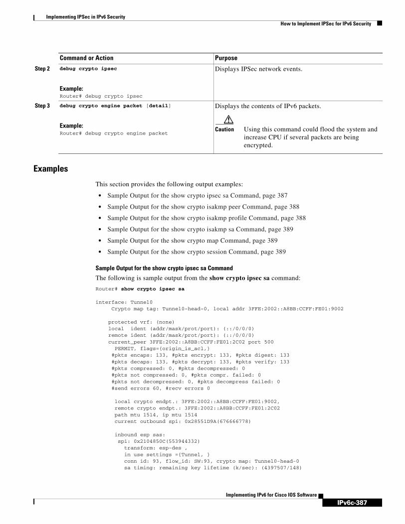
IPv6c-387
Implementing IPSec in IPv6 SecurityHow to Implement IPSec for IPv6 Security
Implementing IPv6 for Cisco IOS Software
Examples
This section provides the following output examples:
• Sample Output for the show crypto ipsec sa Command, page 387
• Sample Output for the show crypto isakmp peer Command, page 388
• Sample Output for the show crypto isakmp profile Command, page 388
• Sample Output for the show crypto isakmp sa Command, page 389
• Sample Output for the show crypto map Command, page 389
• Sample Output for the show crypto session Command, page 389
Sample Output for the show crypto ipsec sa Command
The following is sample output from the show crypto ipsec sa command:
Router# show crypto ipsec sa
interface: Tunnel0 Crypto map tag: Tunnel0-head-0, local addr 3FFE:2002::A8BB:CCFF:FE01:9002
protected vrf: (none) local ident (addr/mask/prot/port): (::/0/0/0) remote ident (addr/mask/prot/port): (::/0/0/0) current_peer 3FFE:2002::A8BB:CCFF:FE01:2C02 port 500 PERMIT, flags={origin_is_acl,} #pkts encaps: 133, #pkts encrypt: 133, #pkts digest: 133 #pkts decaps: 133, #pkts decrypt: 133, #pkts verify: 133 #pkts compressed: 0, #pkts decompressed: 0 #pkts not compressed: 0, #pkts compr. failed: 0 #pkts not decompressed: 0, #pkts decompress failed: 0 #send errors 60, #recv errors 0
local crypto endpt.: 3FFE:2002::A8BB:CCFF:FE01:9002, remote crypto endpt.: 3FFE:2002::A8BB:CCFF:FE01:2C02 path mtu 1514, ip mtu 1514 current outbound spi: 0x28551D9A(676666778)
inbound esp sas: spi: 0x2104850C(553944332) transform: esp-des , in use settings ={Tunnel, } conn id: 93, flow_id: SW:93, crypto map: Tunnel0-head-0 sa timing: remaining key lifetime (k/sec): (4397507/148)
Step 2 debug crypto ipsec
Example:Router# debug crypto ipsec
Displays IPSec network events.
Step 3 debug crypto engine packet [detail]
Example:Router# debug crypto engine packet
Displays the contents of IPv6 packets.
Caution Using this command could flood the system and increase CPU if several packets are being encrypted.
Command or Action Purpose

IPv6c-388
Implementing IPSec in IPv6 SecurityHow to Implement IPSec for IPv6 Security
Implementing IPv6 for Cisco IOS Software
IV size: 8 bytes replay detection support: Y Status: ACTIVE
inbound ah sas: spi: 0x967698CB(2524354763) transform: ah-sha-hmac , in use settings ={Tunnel, } conn id: 93, flow_id: SW:93, crypto map: Tunnel0-head-0 sa timing: remaining key lifetime (k/sec): (4397507/147) replay detection support: Y Status: ACTIVE
inbound pcp sas:
outbound esp sas: spi: 0x28551D9A(676666778) transform: esp-des , in use settings ={Tunnel, } conn id: 94, flow_id: SW:94, crypto map: Tunnel0-head-0 sa timing: remaining key lifetime (k/sec): (4397508/147) IV size: 8 bytes replay detection support: Y Status: ACTIVE
outbound ah sas: spi: 0xA83E05B5(2822636981) transform: ah-sha-hmac , in use settings ={Tunnel, } conn id: 94, flow_id: SW:94, crypto map: Tunnel0-head-0 sa timing: remaining key lifetime (k/sec): (4397508/147) replay detection support: Y Status: ACTIVE
outbound pcp sas:
Sample Output for the show crypto isakmp peer Command
The following sample output shows peer descriptions on an IPv6 router:
Router# show crypto isakmp peer detail
Peer: 2001:0DB8:0:1::1 Port: 500 Local: 2001:0DB8:0:2::1Phase1 id: 2001:0DB8:0:1::1flags: NAS Port: 0 (Normal)IKE SAs: 1 IPSec SA bundles: 1last_locker: 0x141A188, last_last_locker: 0x0last_unlocker: 0x0, last_last_unlocker: 0x0
Sample Output for the show crypto isakmp profile Command
The following sample output shows the ISAKMP profiles that are defined on an IPv6 router.
Router# show crypto isakmp profile
ISAKMP PROFILE tomIdentities matched are:ipv6-address 2001:0DB8:0:1::1/32 Certificate maps matched are:Identity presented is: ipv6-address fqdnkeyring(s): <none>trustpoint(s): <all>

IPv6c-389
Implementing IPSec in IPv6 SecurityHow to Implement IPSec for IPv6 Security
Implementing IPv6 for Cisco IOS Software
Sample Output for the show crypto isakmp sa Command
The following sample output shows the SAs of an active IPv6 device. The IPv4 device is inactive:
Router# show crypto isakmp sa detail
Codes: C - IKE configuration mode, D - Dead Peer Detection K - Keepalives, N - NAT-traversal X - IKE Extended Authentication psk - Preshared key, rsig - RSA signature renc - RSA encryptionIPv4 Crypto ISAKMP SA
C-id Local Remote I-VRF Status Encr Hash Auth DH Lifetime Cap.
IPv6 Crypto ISAKMP SA
dst: 3FFE:2002::A8BB:CCFF:FE01:2C02 src: 3FFE:2002::A8BB:CCFF:FE01:9002 conn-id: 1001 I-VRF: Status: ACTIVE Encr: des Hash: sha Auth: psk DH: 1 Lifetime: 23:45:00 Cap: D Engine-id:Conn-id = SW:1
dst: 3FFE:2002::A8BB:CCFF:FE01:2C02 src: 3FFE:2002::A8BB:CCFF:FE01:9002 conn-id: 1002 I-VRF: Status: ACTIVE Encr: des Hash: sha Auth: psk DH: 1 Lifetime: 23:45:01 Cap: D Engine-id:Conn-id = SW:2
Sample Output for the show crypto map Command
The following sample output shows the dynamically generated crypto maps of an active IPv6 device:
Router# show crypto map
Crypto Map "Tunnel1-head-0" 65536 ipsec-isakmpProfile name: profile0Security association lifetime: 4608000 kilobytes/300 secondsPFS (Y/N): NTransform sets={
ts,}
Crypto Map "Tunnel1-head-0" 65537Map is a PROFILE INSTANCE.Peer = 2001:1::2
IPv6 access list Tunnel1-head-0-ACL (crypto)permit ipv6 any any (61445999 matches) sequence 1
Current peer: 2001:1::2Security association lifetime: 4608000 kilobytes/300 secondsPFS (Y/N): NTransform sets={
ts,}Interfaces using crypto map Tunnel1-head-0:Tunnel1
Sample Output for the show crypto session Command
The following output from the show crypto session information provides details on currently active crypto sessions:
Router# show crypto session detail

IPv6c-390
Implementing IPSec in IPv6 SecurityConfiguration Examples for IPSec for IPv6 Security
Implementing IPv6 for Cisco IOS Software
Crypto session current status
Code: C - IKE Configuration mode, D - Dead Peer Detection K - Keepalives, N - NAT-traversal, X - IKE Extended Authentication
Interface: Tunnel1Session status: UP-ACTIVEPeer: 2001:1::1 port 500 fvrf: (none) ivrf: (none) Phase1_id: 2001:1::1 Desc: (none) IKE SA: local 2001:1::2/500 remote 2001:1::1/500 Active Capabilities:(none) connid:14001 lifetime:00:04:32 IPSEC FLOW: permit ipv6 ::/0 ::/0 Active SAs: 4, origin: crypto map Inbound: #pkts dec'ed 42641 drop 0 life (KB/Sec) 4534375/72 Outbound: #pkts enc'ed 6734980 drop 0 life (KB/Sec) 2392402/72
Configuration Examples for IPSec for IPv6 SecurityThis section provides the following configuration example:
• Configuring a VTI for Site-to-Site IPv6 IPSec Protection: Example, page 390
Configuring a VTI for Site-to-Site IPv6 IPSec Protection: ExampleThe following example shows configuration for a single IPv6 IPSec tunnel:
crypto isakmp policy 1authentication pre-share
!crypto isakmp key myPreshareKey0 address ipv6 3FFE:2002::A8BB:CCFF:FE01:2C02/128crypto isakmp keepalive 30 30!crypto ipsec transform-set 3des ah-sha-hmac esp-3des !crypto ipsec profile profile0
set transform-set 3des !ipv6 cef!interface Tunnel0
ipv6 address 3FFE:1001::/64 eui-64ipv6 enableipv6 ceftunnel source Ethernet2/0tunnel destination 3FFE:2002::A8BB:CCFF:FE01:2C02tunnel mode ipsec ipv6tunnel protection ipsec profile profile0
Additional ReferencesFor additional information related to implementing security for IPv6, see the following sections:
• Related Documents, page 391
• Standards, page 391

IPv6c-391
Implementing IPSec in IPv6 SecurityAdditional References
Implementing IPv6 for Cisco IOS Software
• MIBs, page 391
• RFCs, page 392
• Technical Assistance, page 392
Related Documents
Standards
MIBs
Related Topic Document Title
OSPF for IPv6 authentication support with IPSec Implementing OSPF for IPv6, Release 12.4
IPSec VTI information IPSec Virtual Tunnel Interface, Release 12.3(14)T
IPv6 supported feature list Start Here: Cisco IOS Software Release Specifics for IPv6 Features
IPv6 commands: complete command syntax, command mode, defaults, usage guidelines, and examples
IPv6 for Cisco IOS Command Reference
IPv4 security configuration tasks Cisco IOS Security Configuration Guide, Release 12.4
IPv4 security commands: complete command syntax, command mode, defaults, usage guidelines, and examples
Cisco IOS Security Command Reference, Release 12.4
IPv4 configuration and command reference information
Cisco IOS Release 12.4 Configuration Guides and Command References
Standards Title
No new or modified standards are supported by this feature, and support for existing standards has not been modified by this feature.
—
MIBs MIBs Link
No new or modified MIBs are supported by this feature, and support for existing MIBs has not been modified by this feature.
To locate and download MIBs for selected platforms, Cisco IOS releases, and feature sets, use Cisco MIB Locator found at the following URL:
http://www.cisco.com/go/mibs

IPv6c-392
Implementing IPSec in IPv6 SecurityAdditional References
Implementing IPv6 for Cisco IOS Software
RFCs
Technical Assistance
RFCs Title
RFC 2401 Security Architecture for the Internet Protocol
RFC 2402 IP Authentication Header
RFC 2404 The Use of Hash Message Authentication Code Federal Information Processing Standard 180-1 within Encapsulating Security Payload and Authentication Header
RFC 2406 IP Encapsulating Security Payload (ESP)
RFC 2407 The Internet Security Domain of Interpretation for ISAKMP
RFC 2408 Internet Security Association and Key Management Protocol (ISAKMP)
RFC 2409 Internet Key Exchange (IKE)
RFC 2460 Internet Protocol, Version 6 (IPv6) Specification
RFC 2474 Definition of the Differentiated Services Field (DS Field) in the IPv4 and IPv6 Headers
RFC 3576 Change of Authorization
Description Link
The Cisco Technical Support website contains thousands of pages of searchable technical content, including links to products, technologies, solutions, technical tips, and tools. Registered Cisco.com users can log in from this page to access even more content.
http://www.cisco.com/techsupport

IPv6c-393Implementing IPv6 for Cisco IOS Software
Implementing Traffic Filters and Firewalls for IPv6 Security
The Implementing Traffic Filters and Firewalls for IPv6 Security module describes how to configure Cisco IOS IPv6 traffic filter and firewall features for your Cisco networking devices. These security features can protect your network against degradation or failure and also against data loss or compromise resulting from intentional attacks and from unintended but damaging mistakes by well-meaning network users.
Finding Support Information for Platforms and Cisco IOS Software Images
Use Cisco Feature Navigator to find information about platform support and Cisco IOS software image support. Access Cisco Feature Navigator at http://www.cisco.com/go/fn. You must have an account on Cisco.com. If you do not have an account or have forgotten your username or password, click Cancel at the login dialog box and follow the instructions that appear.
Contents• Prerequisites for Implementing Traffic Filters and Firewalls for IPv6 Security, page 393
• Information About Implementing Traffic Filters and Firewalls for IPv6 Security, page 394
• How to Implement Traffic Filters and Firewalls for IPv6 Security, page 396
• Configuration Examples for Implementing Traffic Filters and Firewalls for IPv6 Security, page 418
• Additional References, page 421
Prerequisites for Implementing Traffic Filters and Firewalls for IPv6 Security
• You should be familiar with IPv4. Refer to the publications referenced in the “Related Documents” section for IPv4 configuration and command reference information.
• You should be familiar with IPv6 addressing and basic configuration. Refer to the Implementing Basic Connectivity for IPv6 module for more information.
Table 16 identifies the earliest release for each early-deployment train in which the feature became available.

IPv6c-394
Implementing Traffic Filters and Firewalls for IPv6 SecurityInformation About Implementing Traffic Filters and Firewalls for IPv6 Security
Implementing IPv6 for Cisco IOS Software
Information About Implementing Traffic Filters and Firewalls for IPv6 Security
To implement security features for IPv6, you need to understand the following concepts:
• Access Control Lists for IPv6 Traffic Filtering, page 394
• Cisco IOS Firewall for IPv6, page 394
Access Control Lists for IPv6 Traffic FilteringCisco IOS Release 12.2(2)T through Cisco IOS Release 12.2(13)T and Cisco IOS Release 12.0(21)ST and later releases support only standard IPv6 ACL functionality. This functionality is similar to standard ACLs in IPv4. Access lists determine what traffic is blocked and what traffic is forwarded at router interfaces and allow filtering based on source and destination addresses, inbound and outbound to a specific interface. Each access list has an implicit deny statement at the end. IPv6 ACLs are defined and their deny and permit conditions are set using the ipv6 access-list command with the deny and permit keywords in global configuration mode.
In Cisco IOS Release 12.0(23)S and 12.2(13)T or later releases, the standard IPv6 ACL functionality is extended to support traffic filtering based on IPv6 option headers and optional, upper-layer protocol type information for finer granularity of control (functionality similar to extended ACLs in IPv4).
Cisco IOS Firewall for IPv6Cisco IOS Firewall is a feature that provides advanced traffic filtering functionality as an integral part of a network’s firewall. Cisco IOS Firewall for IPv6 enables you to implement Cisco IOS Firewall in IPv6 networks. Cisco IOS Firewall coexists with Cisco IOS Firewall for IPv4 networks and is supported on all dual-stack routers.
Cisco IOS Firewall for IPv6 includes the following features:
Table 16 Minimum Required Cisco IOS Release
FeatureMinimum Required Cisco IOS Release by Release Train
Standard access control lists 12.2(2)T, 12.0(21)ST, 12.0(22)S, 12.2(14)S, 12.3, 12.3(2)T, 12.4, 12.4(2)T, 12.2(28)SB
Extended ACLs1
1. IPv6 extended access control lists and IPv6 provider edge router over Multiprotocol Label Switching (MPLS) are implemented with hardware acceleration on the Cisco 12000 series Internet router IP service engineer (ISE) line cards in Cisco IOS routers in Cisco IOS Release 12.0(25)S and later releases.
12.0(23)S, 12.2(13)T, 12.2(14)S, 12.3, 12.3(2)T, 12.4, 12.4(2)T, 12.2(28)SB
IPv6 IOS Firewall 12.3(7)T, 12.4, 12.4(2)T
IPv6 FTP Firewall inspection 12.3(11)T, 12.4, 12.4(2)T
IPv6 ACL enhancements 12.4(2)T
IPv6c-395
Implementing Traffic Filters and Firewalls for IPv6 SecurityInformation About Implementing Traffic Filters and Firewalls for IPv6 Security
Implementing IPv6 for Cisco IOS Software
• Fragmented packet inspection—The fragment header is used to trigger fragment processing. Cisco IOS Firewall virtual fragment reassembly (VFR) examines out-of-sequence fragments and switches the packets into correct order, examines the number of fragments from a single IP given a unique identifier (Denial of Service [DoS] attack), and performs virtual reassembly to hand off packets to upper-layer protocols.
• IPv6 DoS attack mitigation—Mitigation mechanisms have been implemented in the same fashion as for IPv4 implementation, including SYN half-open connections.
• Tunneled packet inspection—Tunneled IPv6 packets terminated at a Cisco IOS firewall router can be inspected by the Cisco IOS Firewall for IPv6.
• Stateful packet inspection—Stateful packet inspection of TCP, User Datagram Protocol (UDP), Internet Control Message Protocol version 6 (ICMPv6), and FTP sessions.
• Stateful inspection of packets originating from the IPv4 network and terminating in an IPv6 environment—This feature uses IPv4-to-IPv6 translation services.
• Interpretation or recognition of most IPv6 Extension Header information—IPv6 Extension Header information including routing header, hop-by-hop Options header, and fragment header is interpreted or recognized.
• Port-to-application mapping (PAM)—Cisco IOS Firewall for IPv6 includes PAM.
PAM in Cisco IOS Firewall for IPv6
PAM allows you to customize TCP or UDP port numbers for network services or applications. PAM uses this information to support network environments that run services using ports that are different from the registered or well-known ports associated with an application.
Using the port information, PAM establishes a table of default port-to-application mapping information at the firewall. The information in the PAM table enables Context-based Access Control (CBAC) supported services to run on nonstandard ports. CBAC was limited to inspecting traffic using only the well-known or registered ports associated with an application, whereas PAM allows network administrators to customize network access control for specific applications and services.
PAM also supports host or subnet specific port mapping, which allows you to apply PAM to a single host or subnet using standard ACLs. Host or subnet specific port mapping is done using standard ACLs.
Cisco IOS Firewall Alerts, Audit Trails, and System Logging
Cisco IOS Firewall generates real-time alerts and audit trails based on events tracked by the firewall. Enhanced audit trail features use system logging to track all network transactions; to record time stamps, source host, destination host, and ports used; and to record the total number of transmitted bytes for advanced, session-based reporting. Real-time alerts send system logging error messages to central management consoles when the system detects suspicious activity. Using Cisco IOS Firewall inspection rules, you can configure alerts and audit trail information on a per-application protocol basis. For example, if you want to generate audit trail information for TCP traffic, you can specify the generation of this information in the Cisco IOS Firewall rule that defines TCP inspection.
The Cisco IOS Firewall provides audit trail messages to record details about inspected sessions. Audit trail information is configurable on a per-application basis using the CBAC inspection rules. To determine which protocol was inspected, use the port number associated with the responder. The port number appears immediately after the address.

IPv6c-396
Implementing Traffic Filters and Firewalls for IPv6 SecurityHow to Implement Traffic Filters and Firewalls for IPv6 Security
Implementing IPv6 for Cisco IOS Software
IPv6 Packet Inspection
The following header fields are all used for IPv6 inspection—traffic class, flow label, payload length, next header, hop limit, and source or destination address. For further information on and descriptions of the IPv6 header fields, see RFC 2474.
Tunneling Support
IPv6 packets tunneled in IPv4 are not inspected. If a tunnel terminates on a router, and IPv6 traffic exiting the tunnel is nonterminating, then the traffic is inspected.
Virtual Fragment Reassembly
When VFR is enabled, VFR processing begins after ACL input lists are checked against incoming packets. The incoming packets are tagged with the appropriate VFR information.
Cisco IOS Firewall Restrictions
Cisco IOS Intrusion Detection System (IDS) is not supported for IPv6.
How to Implement Traffic Filters and Firewalls for IPv6 SecurityThe tasks in the following sections explain how to configure security features for IPv6:
• Configuring IPv6 Traffic Filtering, page 396
• Controlling Access to a vty, page 402
• Configuring Cisco IOS Firewall for IPv6, page 405
• Verifying IPv6 Security Configuration and Operation, page 411
• Troubleshooting IPv6 Security Configuration and Operation, page 413
Configuring IPv6 Traffic FilteringTo enable IPv6 traffic filtering, you must perform the following steps:
1. Create an IPv6 ACL
2. Configure the IPv6 ACL to pass or block traffic
3. Apply the IPv6 ACL to an interface
If you are running Cisco IOS Release 12.2(13)T, 12.0(23)S or later releases, proceed to the “Creating and Configuring an IPv6 ACL for Traffic Filtering” section. If you are running Cisco IOS Release 12.2(11)T, 12.0(22)S, 12.0(21)ST or earlier releases, proceed to the “Creating an IPv6 ACL for Traffic Filtering for Older Releases” section.
Restrictions
IPv6 ACLs are defined by a unique name (IPv6 does not support numbered ACLs). An IPv4 ACL and an IPv6 ACL cannot share the same name.

IPv6c-397
Implementing Traffic Filters and Firewalls for IPv6 SecurityHow to Implement Traffic Filters and Firewalls for IPv6 Security
Implementing IPv6 for Cisco IOS Software
Creating and Configuring an IPv6 ACL for Traffic Filtering
This part describes how to configure your networking devices to filter traffic, function as a firewall, or detect potential viruses. The following task explains how to create an IPv6 ACL and configure the IPv6 ACL to filter traffic in Cisco IOS Release 12.2(13)T and 12.0(23)S or later releases.
Prerequisites
In Cisco IOS Release 12.2(13)T and 12.0(23)S or later releases, for backward compatibility, the ipv6 access-list command with the deny and permit keywords in global configuration mode is still supported; however, an IPv6 ACL defined with deny and permit conditions in global configuration mode is translated to IPv6 access list configuration mode. See the “Create and Apply IPv6 ACL: Examples” section for an example of a translated IPv6 ACL configuration.
Restrictions
• Each IPv6 ACL contains implicit permit rules to enable IPv6 neighbor discovery. These rules can be overridden by the user by placing a deny ipv6 any any statement within an ACL. The IPv6 neighbor discovery process makes use of the IPv6 network layer service; therefore, by default, IPv6 ACLs implicitly allow IPv6 neighbor discovery packets to be sent and received on an interface. In IPv4, the Address Resolution Protocol (ARP), which is equivalent to the IPv6 neighbor discovery process, makes use of a separate data link layer protocol; therefore, by default, IPv4 ACLs implicitly allow ARP packets to be sent and received on an interface.
• Time-based and reflexive ACLs are not supported for IPv4 or IPv6 on the Cisco 12000 series platform. The reflect, timeout, and time-range keywords of the permit command in IPv6 are excluded on the Cisco 12000 series.
SUMMARY STEPS
1. enable
2. configure terminal
3. ipv6 access-list access-list-name
4. permit protocol {source-ipv6-prefix/prefix-length | any | host source-ipv6-address} [operator [port-number]] {destination-ipv6-prefix/prefix-length | any | host destination-ipv6-address} [operator [port-number]] [dest-option-type [doh-number | doh-type]] [dscp value] [flow-label value] [fragments] [log] [log-input] [mobility] [mobility-type [mh-number | mh-type]] [reflect name [timeout value]] [routing] [routing-type routing-number] [sequence value] [time-range name]ordeny protocol {source-ipv6-prefix/prefix-length | any | host source-ipv6-address} [operator [port-number]] {destination-ipv6-prefix/prefix-length | any | host destination-ipv6-address} [operator [port-number]] [dest-option-type [doh-number | doh-type]] [dscp value] [flow-label value] [fragments] [log] [log-input] [mobility] [mobility-type [mh-number | mh-type]] [routing] [routing-type routing-number] [sequence value] [time-range name] [undetermined-transport]

IPv6c-398
Implementing Traffic Filters and Firewalls for IPv6 SecurityHow to Implement Traffic Filters and Firewalls for IPv6 Security
Implementing IPv6 for Cisco IOS Software
DETAILED STEPS
Command or Action Purpose
Step 1 enable
Example:Router> enable
Enables privileged EXEC mode.
• Enter your password if prompted.
Step 2 configure terminal
Example:Router# configure terminal
Enters global configuration mode.
Step 3 ipv6 access-list access-list-name
Example:Router(config)# ipv6 access-list outbound
Defines an IPv6 ACL and enters IPv6 access list configuration mode. The router prompt changes to Router(config-ipv6-acl)#.
• The access-list name argument specifies the name of the IPv6 ACL. IPv6 ACL names cannot contain a space or quotation mark, or begin with a numeral.
Step 4 permit protocol {source-ipv6-prefix/prefix-length | any | host source-ipv6-address} [operator [port-number]] {destination-ipv6-prefix/prefix-length | any | host destination-ipv6-address} [operator [port-number]] [dest-option-type [doh-number | doh-type]] [dscp value] [flow-label value] [fragments] [log] [log-input] [mobility] [mobility-type [mh-number | mh-type]] [reflect name [timeout value]] [routing] [routing-type routing-number] [sequence value] [time-range name]
or
deny protocol {source-ipv6-prefix/prefix-length | any | host source-ipv6-address} [operator [port-number]] {destination-ipv6-prefix/prefix-length | any | host destination-ipv6-address} [operator [port-number]] [dest-option-type [doh-number | doh-type]] [dscp value] [flow-label value] [fragments] [log] [log-input] [mobility] [mobility-type [mh-number | mh-type]] [routing] [routing-type routing-number] [sequence value] [time-range name] [undetermined-transport]
Example:Router(config-ipv6-acl)# permit tcp 2001:0DB8:0300:0201::/32 eq telnet any reflect reflectout
Example:Router(config-ipv6-acl)# deny tcp host 2001:0db8:1::1 any log-input
Specifies permit or deny conditions for an IPv6 ACL.
• The protocol argument specifies the name or number of an Internet protocol. It can be one of the keywords ahp, esp, icmp, ipv6, pcp, sctp, tcp, or udp, or an integer in the range from 0 to 255 representing an IPv6 protocol number.
• The source-ipv6-prefix/prefix-length and destination-ipv6-prefix/prefix-length arguments specify the source and destination IPv6 network or class of networks about which to set permit conditions.
• These arguments must be in the form documented in RFC 2373 where the address is specified in hexadecimal using 16-bit values between colons.
• The any keyword is an abbreviation for the IPv6 prefix ::/0.
• The host source-ipv6-address keyword and argument specify the source IPv6 host address about which to set permit conditions.
• The source-ipv6-address argument must be in the form documented in RFC 2373 where the address is specified in hexadecimal using 16-bit values between colons.
• Refer to the permit and deny commands in the IPv6 for Cisco IOS Command Reference document for information on supported arguments and keywords.
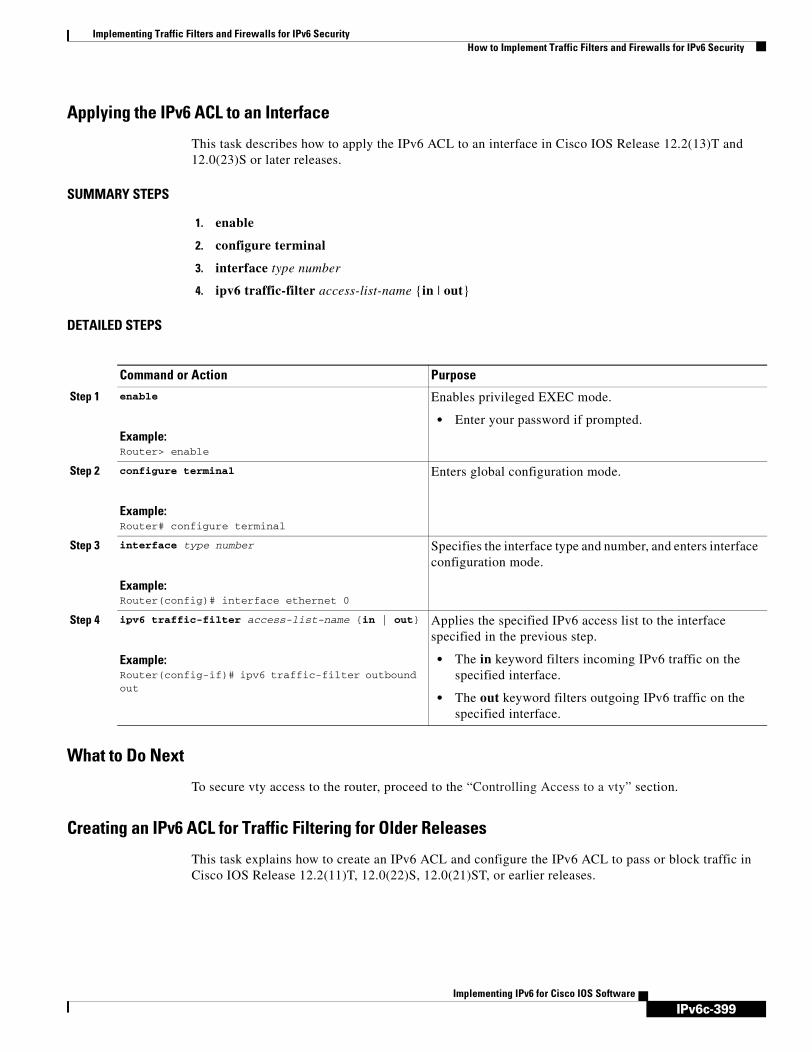
IPv6c-399
Implementing Traffic Filters and Firewalls for IPv6 SecurityHow to Implement Traffic Filters and Firewalls for IPv6 Security
Implementing IPv6 for Cisco IOS Software
Applying the IPv6 ACL to an Interface
This task describes how to apply the IPv6 ACL to an interface in Cisco IOS Release 12.2(13)T and 12.0(23)S or later releases.
SUMMARY STEPS
1. enable
2. configure terminal
3. interface type number
4. ipv6 traffic-filter access-list-name {in | out}
DETAILED STEPS
What to Do Next
To secure vty access to the router, proceed to the “Controlling Access to a vty” section.
Creating an IPv6 ACL for Traffic Filtering for Older Releases
This task explains how to create an IPv6 ACL and configure the IPv6 ACL to pass or block traffic in Cisco IOS Release 12.2(11)T, 12.0(22)S, 12.0(21)ST, or earlier releases.
Command or Action Purpose
Step 1 enable
Example:Router> enable
Enables privileged EXEC mode.
• Enter your password if prompted.
Step 2 configure terminal
Example:Router# configure terminal
Enters global configuration mode.
Step 3 interface type number
Example:Router(config)# interface ethernet 0
Specifies the interface type and number, and enters interface configuration mode.
Step 4 ipv6 traffic-filter access-list-name {in | out}
Example:Router(config-if)# ipv6 traffic-filter outbound out
Applies the specified IPv6 access list to the interface specified in the previous step.
• The in keyword filters incoming IPv6 traffic on the specified interface.
• The out keyword filters outgoing IPv6 traffic on the specified interface.

IPv6c-400
Implementing Traffic Filters and Firewalls for IPv6 SecurityHow to Implement Traffic Filters and Firewalls for IPv6 Security
Implementing IPv6 for Cisco IOS Software
Restrictions
• The source-ipv6-prefix argument filters traffic by packet source address, and the destination-ipv6-prefix argument filters traffic by packet destination address.
• The Cisco IOS software compares an IPv6 prefix against the permit and deny condition statements in the access list. Every IPv6 access list, including access lists that do not have any permit and deny condition statements, has an implicit deny any any statement as its last match condition. The priority or sequence value applied to each condition statement dictates the order in which the statement is applied in the access list.
SUMMARY STEPS
1. enable
2. configure terminal
3. ipv6 access-list access-list-name {permit | deny} {source-ipv6-prefix/prefix-length | any} {destination-ipv6-prefix/prefix-length | any} [priority value]

IPv6c-401
Implementing Traffic Filters and Firewalls for IPv6 SecurityHow to Implement Traffic Filters and Firewalls for IPv6 Security
Implementing IPv6 for Cisco IOS Software
DETAILED STEPS
Applying the IPv6 ACL to an Interface in Older Releases
This task describes how to apply the IPv6 ACL to an interface in Cisco IOS Release 12.2(11)T, 12.0(22)S, 12.0(21)ST, or earlier releases.
SUMMARY STEPS
1. enable
2. configure terminal
3. interface type number
4. ipv6 traffic-filter access-list-name {in | out}
Command or Action Purpose
Step 1 enable
Example:Router> enable
Enables privileged EXEC mode.
• Enter your password if prompted.
Step 2 configure terminal
Example:Router# configure terminal
Enters global configuration mode.
Step 3 ipv6 access-list access-list-name {permit | deny} {source-ipv6-prefix/prefix-length | any} {destination-ipv6-prefix/prefix-length | any} [priority value]
Example:Router(config)# ipv6 access-list list2 deny fec0:0:0:2::/64 any
Defines an IPv6 ACL and sets deny or permit conditions for the ACL.
• The access-list name argument specifies the name of the IPv6 ACL. IPv6 ACL names cannot contain a space or quotation mark, or begin with a numeral.
• The deny keyword specifies deny conditions for the access list.
• The permit keyword specifies permit conditions for the access list.
• The prefix-length argument indicates the number of consecutive, most significant bits that are used in the match. A slash mark must precede the decimal value.
• The any keyword, when specified instead of the source-ipv6-prefix/prefix-length or destination-ipv6-prefix/prefix-length argument, matches any prefix and is equivalent to the IPv6 prefix ::/0.
• The priority keyword specifies the order in which the statement is applied in the access list. The acceptable range is from 1 to 4294967295.

IPv6c-402
Implementing Traffic Filters and Firewalls for IPv6 SecurityHow to Implement Traffic Filters and Firewalls for IPv6 Security
Implementing IPv6 for Cisco IOS Software
DETAILED STEPS
Controlling Access to a vtyThe following two tasks explain how to restrict access to a vty on a router.
• Creating an IPv6 ACL for Access Class Filtering, page 402
• Applying an IPv6 ACL to the Virtual Terminal Line, page 404
Access Class Filtering in IPv6
Filtering incoming and outgoing connections to and from the router based on an IPv6 ACL is performed using the ipv6 access-class command in line configuration mode. The ipv6 access-class command is similar to the access-class command, except the IPv6 ACLs are defined by a name. If the IPv6 ACL is applied to inbound traffic, the source address in the ACL is matched against the incoming connection source address and the destination address in the ACL is matched against the local router address on the interface. If the IPv6 ACL is applied to outbound traffic, the source address in the ACL is matched against the local router address on the interface and the destination address in the ACL is matched against the outgoing connection source address. We recommend that identical restrictions are set on all the virtual terminal lines because a user can attempt to connect to any of them.
Creating an IPv6 ACL for Access Class Filtering
The following task explains how to control access to a vty on a router by creating an IPv6 ACL to provide access class filtering.
Command or Action Purpose
Step 1 enable
Example:Router> enable
Enables privileged EXEC mode.
• Enter your password if prompted.
Step 2 configure terminal
Example:Router# configure terminal
Enters global configuration mode.
Step 3 interface type number
Example:Router(config)# interface ethernet 0
Specifies the interface type and number, and enters interface configuration mode.
Step 4 ipv6 traffic-filter access-list-name {in | out}
Example:Router(config-if)# ipv6 traffic-filter list2 out
Applies the specified IPv6 access list to the interface specified in the previous step.
• The in keyword filters incoming IPv6 traffic on the specified interface.
• The out keyword filters outgoing IPv6 traffic on the specified interface.

IPv6c-403
Implementing Traffic Filters and Firewalls for IPv6 SecurityHow to Implement Traffic Filters and Firewalls for IPv6 Security
Implementing IPv6 for Cisco IOS Software
SUMMARY STEPS
1. enable
2. configure terminal
3. ipv6 access-list access-list-name
4. permit protocol {source-ipv6-prefix/prefix-length | any | host source-ipv6-address} [operator [port-number]] {destination-ipv6-prefix/prefix-length | any | host destination-ipv6-address} [operator [port-number]] [dest-option-type [doh-number | doh-type]] [dscp value] [flow-label value] [fragments] [log] [log-input] [mobility] [mobility-type [mh-number | mh-type]] [reflect name [timeout value]] [routing] [routing-type routing-number] [sequence value] [time-range name]ordeny protocol {source-ipv6-prefix/prefix-length | any | host source-ipv6-address} [operator [port-number]] {destination-ipv6-prefix/prefix-length | any | host destination-ipv6-address} [operator [port-number]] [dest-option-type [doh-number | doh-type]] [dscp value] [flow-label value] [fragments] [log] [log-input] [mobility] [mobility-type [mh-number | mh-type]] [routing] [routing-type routing-number] [sequence value] [time-range name] [undetermined-transport]
DETAILED STEPS
Command or Action Purpose
Step 1 enable
Example:Router> enable
Enables privileged EXEC mode.
• Enter your password if prompted.
Step 2 configure terminal
Example:Router# configure terminal
Enters global configuration mode.

IPv6c-404
Implementing Traffic Filters and Firewalls for IPv6 SecurityHow to Implement Traffic Filters and Firewalls for IPv6 Security
Implementing IPv6 for Cisco IOS Software
Applying an IPv6 ACL to the Virtual Terminal Line
After you have created the IPv6 ACL for access class filtering, you must apply it to a specified virtual terminal line. The following task describes how to apply the ACL to the virtual terminal line.
SUMMARY STEPS
1. enable
2. configure terminal
Step 3 ipv6 access-list access-list-name
Example:Router(config)# ipv6 access-list cisco
Defines an IPv6 ACL and enters IPv6 access list configuration mode. The router prompt changes to Router(config-ipv6-acl)#.
• The access-list name argument specifies the name of the IPv6 ACL. IPv6 ACL names cannot contain a space or quotation mark, or begin with a numeral.
Step 4 permit protocol {source-ipv6-prefix/prefix-length | any | host source-ipv6-address} [operator [port-number]] {destination-ipv6-prefix/prefix-length | any | host destination-ipv6-address} [operator [port-number]] [dest-option-type [doh-number | doh-type]] [dscp value] [flow-label value] [fragments] [log] [log-input] [mobility] [mobility-type [mh-number | mh-type]] [reflect name [timeout value]] [routing] [routing-type routing-number] [sequence value] [time-range name]
or
deny protocol {source-ipv6-prefix/prefix-length | any | host source-ipv6-address} [operator [port-number]] {destination-ipv6-prefix/prefix-length | any | host destination-ipv6-address} [operator [port-number]] [dest-option-type [doh-number | doh-type]] [dscp value] [flow-label value] [fragments] [log] [log-input] [mobility] [mobility-type [mh-number | mh-type]] [routing] [routing-type routing-number] [sequence value] [time-range name] [undetermined-transport]
Example:Router(config-ipv6-acl)# permit ipv6 host 2001:0DB8:0:4::32 any eq telnet
or
Example:Router(config-ipv6-acl)# deny ipv6 host 2001:0DB8:0:6::6/32 any
Specifies permit or deny conditions for an IPv6 ACL.
• The protocol argument specifies the name or number of an Internet protocol. For an access class match against the IPv6 ACL the argument must be either the ipv6 or the tcp keyword. If TCP ports are specified within the ACL, the port ranges must include the ports used to gain access. For incoming connections, for example, the destination port must include the Telnet port.
• The source-ipv6-prefix/prefix-length and destination-ipv6-prefix/prefix-length arguments specify the source and destination IPv6 network or class of networks about which to set permit conditions. These arguments must be in the form documented in RFC 2373 where the address is specified in hexadecimal using 16-bit values between colons.
• The any keyword is an abbreviation for the IPv6 prefix ::/0.
• The host source-ipv6-address keyword and argument specify the source IPv6 host address about which to set permit conditions. The source-ipv6-address argument must be in the form documented in RFC 2373 where the address is specified in hexadecimal using 16-bit values between colons.
• Refer to the permit and deny commands in the IPv6 for Cisco IOS Command Reference document for information on supported arguments and keywords.
Command or Action Purpose
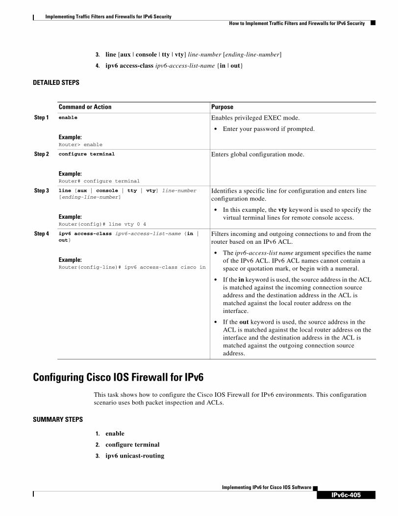
IPv6c-405
Implementing Traffic Filters and Firewalls for IPv6 SecurityHow to Implement Traffic Filters and Firewalls for IPv6 Security
Implementing IPv6 for Cisco IOS Software
3. line [aux | console | tty | vty] line-number [ending-line-number]
4. ipv6 access-class ipv6-access-list-name {in | out}
DETAILED STEPS
Configuring Cisco IOS Firewall for IPv6This task shows how to configure the Cisco IOS Firewall for IPv6 environments. This configuration scenario uses both packet inspection and ACLs.
SUMMARY STEPS
1. enable
2. configure terminal
3. ipv6 unicast-routing
Command or Action Purpose
Step 1 enable
Example:Router> enable
Enables privileged EXEC mode.
• Enter your password if prompted.
Step 2 configure terminal
Example:Router# configure terminal
Enters global configuration mode.
Step 3 line [aux | console | tty | vty] line-number [ending-line-number]
Example:Router(config)# line vty 0 4
Identifies a specific line for configuration and enters line configuration mode.
• In this example, the vty keyword is used to specify the virtual terminal lines for remote console access.
Step 4 ipv6 access-class ipv6-access-list-name {in | out}
Example:Router(config-line)# ipv6 access-class cisco in
Filters incoming and outgoing connections to and from the router based on an IPv6 ACL.
• The ipv6-access-list name argument specifies the name of the IPv6 ACL. IPv6 ACL names cannot contain a space or quotation mark, or begin with a numeral.
• If the in keyword is used, the source address in the ACL is matched against the incoming connection source address and the destination address in the ACL is matched against the local router address on the interface.
• If the out keyword is used, the source address in the ACL is matched against the local router address on the interface and the destination address in the ACL is matched against the outgoing connection source address.

IPv6c-406
Implementing Traffic Filters and Firewalls for IPv6 SecurityHow to Implement Traffic Filters and Firewalls for IPv6 Security
Implementing IPv6 for Cisco IOS Software
4. ipv6 inspect name inspection-name protocol [alert {on | off}] [audit-trail {on | off}] [timeout seconds]
5. interface type number
6. ipv6 address ipv6-address/prefix
7. ipv6 enable
8. ipv6 traffic-filter [inbound | outbound}
9. ipv6 inspect inspect-name
10. ipv6 access-list access-list-name
11. permit protocol {source-ipv6-prefix/prefix-length | any | host source-ipv6-address} [operator [port-number]] {destination-ipv6-prefix/prefix-length | any | host destination-ipv6-address} [operator [port-number]] [dest-option-type [doh-number | doh-type]] [dscp value] [flow-label value] [fragments] [log] [log-input] [mobility] [mobility-type [mh-number | mh-type]] [reflect name [timeout value]] [routing] [routing-type routing-number] [sequence value] [time-range name]ordeny protocol {source-ipv6-prefix/prefix-length | any | host source-ipv6-address} [operator [port-number]] {destination-ipv6-prefix/prefix-length | any | host destination-ipv6-address} [operator [port-number]] [dest-option-type [doh-number | doh-type]] [dscp value] [flow-label value] [fragments] [log] [log-input] [mobility] [mobility-type [mh-number | mh-type]] [routing] [routing-type routing-number] [sequence value] [time-range name] [undetermined-transport]
DETAILED STEPS
Command or Action Purpose
Step 1 enable
Example:Router> enable
Enables privileged EXEC mode.
• Enter your password if prompted.
Step 2 configure terminal
Example:Router# configure terminal
Enters global configuration mode.
Step 3 ipv6 unicast-routing
Example:Router(config)# ipv6 unicast-routing
Enables IPv6 unicast routing.
Step 4 ipv6 inspect name inspection-name protocol [alert {on | off}] [audit-trail {on | off}] [timeout seconds]
Example:Router(config)# ipv6 inspect name ipv6_test icmp timeout 60
Defines a set of IPv6 inspection rules for the firewall.

IPv6c-407
Implementing Traffic Filters and Firewalls for IPv6 SecurityHow to Implement Traffic Filters and Firewalls for IPv6 Security
Implementing IPv6 for Cisco IOS Software
Step 5 interface type number
Example:Router(config)# interface FastEthernet0/0
Specifies the interface on which the inspection will occur.
Step 6 ipv6 address ipv6-address/prefix
Example:Router(config-if)# ipv6 address 3FFE:C000:0:7::/64 eui-64
Provides the address for the inspection interface.
Step 7 ipv6 enable
Example:Router(config-if)# ipv6 enable
Enables IPv6 routing.
Note This step is optional if the IPv6 address is specified in step 6.
Step 8 ipv6 traffic-filter access-list-name {in | out}
Example:Router(config-if)# ipv6 traffic-filter outbound out
Applies the specified IPv6 access list to the interface specified in the previous step.
• The in keyword filters incoming IPv6 traffic on the specified interface.
• The out keyword filters outgoing IPv6 traffic on the specified interface.
Step 9 ipv6 inspect inspection-name {in | out}
Example:Router(config)#ipv6 inspect ipv6_test in
Applies the set of inspection rules.
Command or Action Purpose

IPv6c-408
Implementing Traffic Filters and Firewalls for IPv6 SecurityHow to Implement Traffic Filters and Firewalls for IPv6 Security
Implementing IPv6 for Cisco IOS Software
Configuring PAM for IPv6
The tasks in the following sections explain how to configure PAM for IPv6.
• Creating an IPv6 Access Class Filter for PAM, page 408
• Applying the IPv6 Access Class Filter to PAM, page 410
Creating an IPv6 Access Class Filter for PAM
The following task explains how to create an IPv6 access class filter to use in PAM configuration:
Step 10 ipv6 access-list acl-name
Example:Router(config)# ipv6 access-list outbound
Defines an IPv6 ACL and enters IPv6 access list configuration mode. The router prompt changes to Router(config-ipv6-acl)#.
• The access-list name argument specifies the name of the IPv6 ACL. IPv6 ACL names cannot contain a space or quotation mark, or begin with a numeral.
Step 11 permit protocol {source-ipv6-prefix/prefix-length | any | host source-ipv6-address} [operator [port-number]] {destination-ipv6-prefix/prefix-length | any | host destination-ipv6-address} [operator [port-number]] [dest-option-type [doh-number | doh-type]] [dscp value] [flow-label value] [fragments] [log] [log-input] [mobility] [mobility-type [mh-number | mh-type]] [reflect name [timeout value]] [routing] [routing-type routing-number] [sequence value] [time-range name]
or
deny protocol {source-ipv6-prefix/prefix-length | any | host source-ipv6-address} [operator [port-number]] {destination-ipv6-prefix/prefix-length | any | host destination-ipv6-address} [operator [port-number]] [dest-option-type [doh-number | doh-type]] [dscp value] [flow-label value] [fragments] [log] [log-input] [mobility] [mobility-type [mh-number | mh-type]] [routing] [routing-type routing-number] [sequence value] [time-range name] [undetermined-transport]
Example:Router(config-ipv6-acl)# permit tcp 2001:0DB8:0300:0201::/32 any reflect reflectout
or
Example:Router(config-ipv6-acl)# deny tcp fec0:0:0:0201::/64 any
Specifies permit or deny conditions for an IPv6 ACL.
• The protocol argument specifies the name or number of an Internet protocol. It can be one of the keywords ahp, esp, icmp, ipv6, pcp, sctp, tcp, or udp, or an integer in the range from 0 to 255 representing an IPv6 protocol number.
• The source-ipv6-prefix/prefix-length and destination-ipv6-prefix/prefix-length arguments specify the source and destination IPv6 network or class of networks about which to set permit conditions.
• These arguments must be in the form documented in RFC 2373 where the address is specified in hexadecimal using 16-bit values between colons.
• The any keyword is an abbreviation for the IPv6 prefix ::/0.
• The host source-ipv6-address keyword and argument specify the source IPv6 host address about which to set permit conditions.
• The source-ipv6-address argument must be in the form documented in RFC 2373 where the address is specified in hexadecimal using 16-bit values between colons.
• Refer to the permit and deny commands in the IPv6 for Cisco IOS Command Reference document for information on supported arguments and keywords.
Command or Action Purpose

IPv6c-409
Implementing Traffic Filters and Firewalls for IPv6 SecurityHow to Implement Traffic Filters and Firewalls for IPv6 Security
Implementing IPv6 for Cisco IOS Software
SUMMARY STEPS
1. enable
2. configure terminal
3. ipv6 access-list acl-name
4. permit protocol {source-ipv6-prefix/prefix-length | any | host source-ipv6-address} [operator [port-number]] {destination-ipv6-prefix/prefix-length | any | host destination-ipv6-address} [operator [port-number]] [dest-option-type [doh-number | doh-type]] [dscp value] [flow-label value] [fragments] [log] [log-input] [mobility] [mobility-type [mh-number | mh-type]] [reflect name [timeout value]] [routing] [routing-type routing-number] [sequence value] [time-range name]or deny protocol {source-ipv6-prefix/prefix-length | any | host source-ipv6-address} [operator [port-number]] {destination-ipv6-prefix/prefix-length | any | host destination-ipv6-address} [operator [port-number]] [dest-option-type [doh-number | doh-type]] [dscp value] [flow-label value] [fragments] [log] [log-input] [mobility] [mobility-type [mh-number | mh-type]] [routing] [routing-type routing-number] [sequence value] [time-range name] [undetermined-transport]
DETAILED STEPS
Command or Action Purpose
Step 1 enable
Example:Router> enable
Enables privileged EXEC mode.
• Enter your password if prompted.
Step 2 configure terminal
Example:Router# configure terminal
Enters global configuration mode.
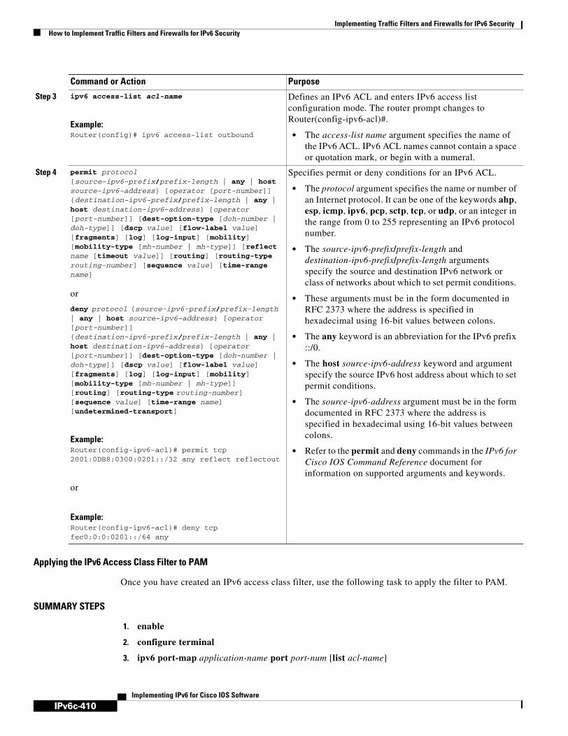
IPv6c-410
Implementing Traffic Filters and Firewalls for IPv6 SecurityHow to Implement Traffic Filters and Firewalls for IPv6 Security
Implementing IPv6 for Cisco IOS Software
Applying the IPv6 Access Class Filter to PAM
Once you have created an IPv6 access class filter, use the following task to apply the filter to PAM.
SUMMARY STEPS
1. enable
2. configure terminal
3. ipv6 port-map application-name port port-num [list acl-name]
Step 3 ipv6 access-list acl-name
Example:Router(config)# ipv6 access-list outbound
Defines an IPv6 ACL and enters IPv6 access list configuration mode. The router prompt changes to Router(config-ipv6-acl)#.
• The access-list name argument specifies the name of the IPv6 ACL. IPv6 ACL names cannot contain a space or quotation mark, or begin with a numeral.
Step 4 permit protocol {source-ipv6-prefix/prefix-length | any | host source-ipv6-address} [operator [port-number]] {destination-ipv6-prefix/prefix-length | any | host destination-ipv6-address} [operator [port-number]] [dest-option-type [doh-number | doh-type]] [dscp value] [flow-label value] [fragments] [log] [log-input] [mobility] [mobility-type [mh-number | mh-type]] [reflect name [timeout value]] [routing] [routing-type routing-number] [sequence value] [time-range name]
or
deny protocol {source-ipv6-prefix/prefix-length | any | host source-ipv6-address} [operator [port-number]] {destination-ipv6-prefix/prefix-length | any | host destination-ipv6-address} [operator [port-number]] [dest-option-type [doh-number | doh-type]] [dscp value] [flow-label value] [fragments] [log] [log-input] [mobility] [mobility-type [mh-number | mh-type]] [routing] [routing-type routing-number] [sequence value] [time-range name] [undetermined-transport]
Example:Router(config-ipv6-acl)# permit tcp 2001:0DB8:0300:0201::/32 any reflect reflectout
or
Example:Router(config-ipv6-acl)# deny tcp fec0:0:0:0201::/64 any
Specifies permit or deny conditions for an IPv6 ACL.
• The protocol argument specifies the name or number of an Internet protocol. It can be one of the keywords ahp, esp, icmp, ipv6, pcp, sctp, tcp, or udp, or an integer in the range from 0 to 255 representing an IPv6 protocol number.
• The source-ipv6-prefix/prefix-length and destination-ipv6-prefix/prefix-length arguments specify the source and destination IPv6 network or class of networks about which to set permit conditions.
• These arguments must be in the form documented in RFC 2373 where the address is specified in hexadecimal using 16-bit values between colons.
• The any keyword is an abbreviation for the IPv6 prefix ::/0.
• The host source-ipv6-address keyword and argument specify the source IPv6 host address about which to set permit conditions.
• The source-ipv6-address argument must be in the form documented in RFC 2373 where the address is specified in hexadecimal using 16-bit values between colons.
• Refer to the permit and deny commands in the IPv6 for Cisco IOS Command Reference document for information on supported arguments and keywords.
Command or Action Purpose

IPv6c-411
Implementing Traffic Filters and Firewalls for IPv6 SecurityHow to Implement Traffic Filters and Firewalls for IPv6 Security
Implementing IPv6 for Cisco IOS Software
DETAILED STEPS
Verifying IPv6 Security Configuration and OperationThis task explains how to display information to verify the configuration and operation of IPv6 security options. Use the following commands as needed to verify configuration and operation.
SUMMARY STEPS
1. show crypto ipsec sa [map map-name | address | identity | interface interface-type interface-number | peer [vrf fvrf-name] address | vrf ivrf-name | ipv6 [interface-type interface-number]] [detail]
2. show crypto isakmp peer [config | detail]
3. show crypto isakmp profile
4. show crypto isakmp sa [active | standby | detail]
5. show ipv6 access-list [access-list-name]
6. show ipv6 inspect {name inspection-name | config | interfaces | session [detail] | all}
7. show ipv6 prefix-list [detail | summary] [list-name]
8. show ipv6 virtual-reassembly interface interface-type
9. show logging [slot slot-number | summary]
10. show ipv6 port-map [application-name | port port-number]
Command or Action Purpose
Step 1 enable
Example:Router> enable
Enables privileged EXEC mode.
• Enter your password if prompted.
Step 2 configure terminal
Example:Router# configure terminal
Enters global configuration mode.
Step 3 ipv6 port-map application-name port port-num [list acl-name]
Example:Router(config)# ipv6 port-map ftp port 8090 list PAM_ACL
Establishes PAM for the system.

IPv6c-412
Implementing Traffic Filters and Firewalls for IPv6 SecurityHow to Implement Traffic Filters and Firewalls for IPv6 Security
Implementing IPv6 for Cisco IOS Software
DETAILED STEPS
Command or Action Purpose
Step 1 show crypto ipsec sa [map map-name | address | identity | interface interface-type interface-number | peer [vrf fvrf-name] address | vrf ivrf-name | ipv6 [interface-type interface-number]] [detail]
Example:Router# show crypto ipsec sa ipv6
Displays the settings used by current SAs.
Step 2 show crypto isakmp peer [config | detail]
Example:Router# show crypto isakmp peer
Displays peer descriptions.
Step 3 show crypto isakmp profile
Example:Router# show crypto isakmp profile
Lists all the ISAKMP profiles that are defined on a router.
Step 4 show crypto isakmp sa [active | standby | detail]
Example:Router# show crypto isakmp sa
Displays current IKE SAs.
Step 5 show ipv6 access-list [access-list-name]
Example:Router# show ipv6 access-list
Displays the contents of all current IPv6 access lists.
Step 6 show ipv6 inspect {name inspection-name | config | interfaces | session [detail] | all}
Example:Router# show ipv6 inspect interfaces
Displays CBAC configuration and session information.
Step 7 show ipv6 prefix-list [detail | summary] [list-name]
Example:Router# show ipv6 prefix-list
Displays information about an IPv6 prefix list or IPv6 prefix list entries.
Step 8 show ipv6 virtual-reassembly interface interface-type
Example:Router# show ipv6 virtual-reassembly interface e1/1
Displays configuration and statistical information of VFR.

IPv6c-413
Implementing Traffic Filters and Firewalls for IPv6 SecurityHow to Implement Traffic Filters and Firewalls for IPv6 Security
Implementing IPv6 for Cisco IOS Software
Troubleshooting IPv6 Security Configuration and OperationThis optional task explains how to display information to troubleshoot the configuration and operation of IPv6 security options. Use the following commands only as needed to verify configuration and operation.
SUMMARY STEPS
1. enable
2. clear ipv6 access-list [access-list-name]
3. clear ipv6 inspect {session session-number | all}
4. clear ipv6 prefix-list [prefix-list-name] [ipv6-prefix/prefix-length]
5. debug crypto ipsec
6. debug crypto engine packet [detail]
7. debug ipv6 inspect {function-trace | object-creation | object-deletion | events | timers | protocol | detailed}
8. debug ipv6 packet [access-list access-list-name] [detail]
DETAILED STEPS
Step 9 show logging [slot slot-number | summary]
Example:Router# show logging
Displays the state of system logging (syslog) and the contents of the standard system logging buffer.
• Access list entries with the log or log-input keywords will be logged when a packet matches the access list entry.
Step 10 show ipv6 port-map [application-name | port port-number]
Example:Router# show ipv6 port-map ftp
Displays PAM configuration.
Command or Action Purpose
Command or Action Purpose
Step 1 enable
Example:Router# enable
Enables privileged EXEC mode.
• Enter your password if prompted.
Step 2 clear ipv6 access-list [access-list-name]
Example:Router# clear ipv6 access-list tin
Resets the IPv6 access list match counters.
• If the access-list-name argument is specified, only the specified access list counters will be reset.

IPv6c-414
Implementing Traffic Filters and Firewalls for IPv6 SecurityHow to Implement Traffic Filters and Firewalls for IPv6 Security
Implementing IPv6 for Cisco IOS Software
Examples
This section provides the following output examples:
• Sample Output for the show crypto ipsec sa ipv6 Command, page 415
• Sample Output for the show crypto isakmp peer Command, page 416
• Sample Output for the show crypto isakmp profile Command, page 416
• Sample Output for the show crypto isakmp sa Command, page 416
• Sample Output for the show ipv6 access-list Command, page 417
• Sample Output for the show ipv6 prefix-list Command, page 417
• Sample Output for the show ipv6 virtual-reassembly Command, page 417
• Sample Output for the show logging Command, page 418
• Sample Output for the clear ipv6 access-list Command, page 418
Step 3 clear ipv6 inspect {session session-number | all}
Example:Router# clear ipv6 inspect all
Removes a specific IPv6 session or all IPv6 inspection sessions.
Step 4 clear ipv6 prefix-list [prefix-list-name] [ipv6-prefix/prefix-length]
Example:Router# clear ipv6 prefix-list
Resets the hit count of the IPv6 prefix list entries.
Step 5 debug crypto ipsec
Example:Router# debug crypto ipsec
Displays IPSec network events.
Step 6 debug crypto engine packet [detail]
Example:Router# debug crypto engine packet
Displays the contents of IPv6 packets.
Caution Using this command could flood the system and increase CPU if several packets are being encrypted.
Step 7 debug ipv6 inspect {function-trace | object-creation | object-deletion | events | timers | protocol | detailed}
Example:Router# debug ipv6 inspect timers
Displays messages about Cisco IOS Firewall events.
Step 8 debug ipv6 packet [access-list access-list-name] [detail]
Example:Router# debug ipv6 packet access-list PAK-ACL
Displays debugging messages for IPv6 packets.
• If the access-list keyword and access-list-name argument is specified, only packets matching the access list permit entries are displayed.
Command or Action Purpose

IPv6c-415
Implementing Traffic Filters and Firewalls for IPv6 SecurityHow to Implement Traffic Filters and Firewalls for IPv6 Security
Implementing IPv6 for Cisco IOS Software
Sample Output for the show crypto ipsec sa ipv6 Command
The following is sample output from the show crypto ipsec sa ipv6 command:
Router# show crypto ipsec sa ipv6
interface: Tunnel0 Crypto map tag: Tunnel0-head-0, local addr 3FFE:2002::A8BB:CCFF:FE01:9002
protected vrf: (none) local ident (addr/mask/prot/port): (::/0/0/0) remote ident (addr/mask/prot/port): (::/0/0/0) current_peer 3FFE:2002::A8BB:CCFF:FE01:2C02 port 500 PERMIT, flags={origin_is_acl,} #pkts encaps: 133, #pkts encrypt: 133, #pkts digest: 133 #pkts decaps: 133, #pkts decrypt: 133, #pkts verify: 133 #pkts compressed: 0, #pkts decompressed: 0 #pkts not compressed: 0, #pkts compr. failed: 0 #pkts not decompressed: 0, #pkts decompress failed: 0 #send errors 60, #recv errors 0
local crypto endpt.: 3FFE:2002::A8BB:CCFF:FE01:9002, remote crypto endpt.: 3FFE:2002::A8BB:CCFF:FE01:2C02 path mtu 1514, ip mtu 1514 current outbound spi: 0x28551D9A(676666778)
inbound esp sas: spi: 0x2104850C(553944332) transform: esp-des , in use settings ={Tunnel, } conn id: 93, flow_id: SW:93, crypto map: Tunnel0-head-0 sa timing: remaining key lifetime (k/sec): (4397507/148) IV size: 8 bytes replay detection support: Y Status: ACTIVE
inbound ah sas: spi: 0x967698CB(2524354763) transform: ah-sha-hmac , in use settings ={Tunnel, } conn id: 93, flow_id: SW:93, crypto map: Tunnel0-head-0 sa timing: remaining key lifetime (k/sec): (4397507/147) replay detection support: Y Status: ACTIVE
inbound pcp sas:
outbound esp sas: spi: 0x28551D9A(676666778) transform: esp-des , in use settings ={Tunnel, } conn id: 94, flow_id: SW:94, crypto map: Tunnel0-head-0 sa timing: remaining key lifetime (k/sec): (4397508/147) IV size: 8 bytes replay detection support: Y Status: ACTIVE
outbound ah sas: spi: 0xA83E05B5(2822636981) transform: ah-sha-hmac , in use settings ={Tunnel, } conn id: 94, flow_id: SW:94, crypto map: Tunnel0-head-0 sa timing: remaining key lifetime (k/sec): (4397508/147) replay detection support: Y

IPv6c-416
Implementing Traffic Filters and Firewalls for IPv6 SecurityHow to Implement Traffic Filters and Firewalls for IPv6 Security
Implementing IPv6 for Cisco IOS Software
Status: ACTIVE
outbound pcp sas:
Sample Output for the show crypto isakmp peer Command
The following sample output shows peer descriptions on an IPv6 router:
Router# show crypto isakmp peer detail
Peer: 2001:0DB8:0:1::1 Port: 500 Local: 2001:0DB8:0:2::1Phase1 id: 2001:0DB8:0:1::1flags: NAS Port: 0 (Normal)IKE SAs: 1 IPSec SA bundles: 1last_locker: 0x141A188, last_last_locker: 0x0last_unlocker: 0x0, last_last_unlocker: 0x0
Sample Output for the show crypto isakmp profile Command
The following sample output shows the ISAKMP profiles that are defined on an IPv6 router.
Router# show crypto isakmp profile
ISAKMP PROFILE tomIdentities matched are:ipv6-address 2001:0DB8:0:1::1/32 Certificate maps matched are:Identity presented is: ipv6-address fqdnkeyring(s): <none>trustpoint(s): <all>
Sample Output for the show crypto isakmp sa Command
The following sample output shows the SAs of an active IPv6 device. The IPv4 device is inactive:
Router# show crypto isakmp sa detail
Codes: C - IKE configuration mode, D - Dead Peer Detection K - Keepalives, N - NAT-traversal X - IKE Extended Authentication psk - Preshared key, rsig - RSA signature renc - RSA encryptionIPv4 Crypto ISAKMP SA
C-id Local Remote I-VRF Status Encr Hash Auth DH Lifetime Cap.
IPv6 Crypto ISAKMP SA
dst: 3FFE:2002::A8BB:CCFF:FE01:2C02 src: 3FFE:2002::A8BB:CCFF:FE01:9002 conn-id: 1001 I-VRF: Status: ACTIVE Encr: des Hash: sha Auth: psk DH: 1 Lifetime: 23:45:00 Cap: D Engine-id:Conn-id = SW:1
dst: 3FFE:2002::A8BB:CCFF:FE01:2C02 src: 3FFE:2002::A8BB:CCFF:FE01:9002 conn-id: 1002 I-VRF: Status: ACTIVE Encr: des Hash: sha Auth: psk DH: 1 Lifetime: 23:45:01 Cap: D Engine-id:Conn-id = SW:2

IPv6c-417
Implementing Traffic Filters and Firewalls for IPv6 SecurityHow to Implement Traffic Filters and Firewalls for IPv6 Security
Implementing IPv6 for Cisco IOS Software
Sample Output for the show ipv6 access-list Command
In the following example, the show ipv6 access-list command is used to verify that IPv6 ACLs are configured correctly:
Router> show ipv6 access-list
IPv6 access list inbound permit tcp any any eq bgp reflect tcptraffic (8 matches) sequence 10 permit tcp any any eq telnet reflect tcptraffic (15 matches) sequence 20 permit udp any any reflect udptraffic sequence 30
IPv6 access list tcptraffic (reflexive) (per-user) permit tcp host 2001:0DB8:1::32 eq bgp host 2001:0DB8:2::32 eq 11000 timeout 300 (time
left 243) sequence 1 permit tcp host 2001:0DB8:1::32 eq telnet host 2001:0DB8:2::32 eq 11001 timeout 300
(time left 296) sequence 2
IPv6 access list outbound evaluate udptraffic evaluate tcptraffic
Note For a description of each output display field, refer to the show ipv6 access-list command in the IPv6 for Cisco IOS Command Reference document.
Sample Output for the show ipv6 prefix-list Command
The following example shows the output of the show ipv6 prefix-list command with the detail keyword:
Router# show ipv6 prefix-list detail
Prefix-list with the last deletion/insertion: bgp-inipv6 prefix-list 6to4: count: 1, range entries: 0, sequences: 5 - 5, refcount: 2 seq 5 permit 2001:0db8::/32 (hit count: 313, refcount: 1)ipv6 prefix-list aggregate: count: 2, range entries: 2, sequences: 5 - 10, refcount: 30 seq 5 deny 3FFE:C00::/24 ge 25 (hit count: 568, refcount: 1) seq 10 permit ::/0 le 48 (hit count: 31310, refcount: 1)ipv6 prefix-list bgp-in: count: 6, range entries: 3, sequences: 5 - 30, refcount: 31 seq 5 deny 5F00::/8 le 128 (hit count: 0, refcount: 1) seq 10 deny ::/0 (hit count: 0, refcount: 1) seq 15 deny ::/1 (hit count: 0, refcount: 1) seq 20 deny ::/2 (hit count: 0, refcount: 1) seq 25 deny ::/3 ge 4 (hit count: 0, refcount: 1) seq 30 permit ::/0 le 128 (hit count: 240664, refcount: 0)
Sample Output for the show ipv6 virtual-reassembly CommandRouter# show ipv6 virtual-reassembly interface e1/1
Configuration Information:---------------------------------Virtual Fragment Reassembly (VFR) is ENABLED...Maximum number of datagram that can be reassembled at a time: 64Maximum number of fragments per datagram: 8Timeout value of a datagram: 3 seconds
Statistical Information:----------------------------Number of datagram being reassembled:12Number of fragments being processed:48

IPv6c-418
Implementing Traffic Filters and Firewalls for IPv6 SecurityConfiguration Examples for Implementing Traffic Filters and Firewalls for IPv6 Security
Implementing IPv6 for Cisco IOS Software
Total number of datagram reassembled:6950Total number of datagram failed: 9
Sample Output for the show logging Command
In the following example, the show logging command is used to display logging entries that match the first line (sequence 10) of the access list named tin:
Router> show logging
00:00:36: %IPV6-6-ACCESSLOGP: list tin/10 permitted tcp 2001:0db8:1::1(11001) (Ethernet0/0) -> 2001:0db8:1::2(179), 1 packet
Sample Output for the clear ipv6 access-list Command
In the following example, the show ipv6 access-list command is used to display some match counters for the access list named tin. Privileged EXEC mode is entered using the enable command (not shown) and the clear ipv6 access-list EXEC command is issued to reset the match counters for the access list named tin. The show ipv6 access-list EXEC command is used again to show that the match counters have been reset.
Router> show ipv6 access-list tin
IPv6 access list tin permit tcp any any log-input (6 matches) sequence 10 permit icmp any any echo-request log-input sequence 20 permit icmp any any echo-reply log-input sequence 30
Router# clear ipv6 access-list tin
Router# show ipv6 access-list tin
IPv6 access list tin permit tcp any any log-input sequence 10 permit icmp any any echo-request log-input sequence 20 permit icmp any any echo-reply log-input sequence 30
Configuration Examples for Implementing Traffic Filters and Firewalls for IPv6 Security
This section provides the following configuration examples:
• Create and Apply IPv6 ACL: Examples, page 418
• Controlling Access to a vty: Example, page 420
• Configuring Cisco IOS Firewall for IPv6: Example, page 420
Create and Apply IPv6 ACL: Examples
Create and Apply an IPv6 ACL Example for Release 12.2(13)T or 12.0(23)S
The following example is from a router running Cisco IOS Release 12.2(13)T.
The example configures two IPv6 ACLs named OUTBOUND and INBOUND and applies both ACLs to outbound and inbound traffic on Ethernet interface 0. The first and second permit entries in the OUTBOUND list permit all TCP and User Datagram Protocol (UDP) packets from network 2001:0DB8:0300:0201::/32 to exit out of Ethernet interface 0. The entries also configure the temporary

IPv6c-419
Implementing Traffic Filters and Firewalls for IPv6 SecurityConfiguration Examples for Implementing Traffic Filters and Firewalls for IPv6 Security
Implementing IPv6 for Cisco IOS Software
IPv6 reflexive ACL named REFLECTOUT to filter returning (incoming) TCP and UDP packets on Ethernet interface 0. The first deny entry in the OUTBOUND list keeps all packets from the network fec0:0:0:0201::/64 (packets that have the site-local prefix fec0:0:0:0201 as the first 64 bits of their source IPv6 address) from exiting out of Ethernet interface 0.
The evaluate command in the INBOUND list applies the temporary IPv6 reflexive ACL named REFLECTOUT to inbound TCP and UDP packets on Ethernet interface 0. When outgoing TCP or UDP packets are permitted on Ethernet interface 0 by the OUTBOUND list, the INBOUND list uses the REFLECTOUT list to match (evaluate) the returning (incoming) TCP and UDP packets.
ipv6 access-list OUTBOUNDpermit tcp 2001:0DB8:0300:0201::/32 any reflect REFLECTOUTpermit udp 2001:0DB8:0300:0201::/32 any reflect REFLECTOUTdeny fec0:0:0:0201::/64 any
ipv6 access-list INBOUNDevaluate REFLECTOUT
interface ethernet 0ipv6 traffic-filter OUTBOUND outipv6 traffic-filter INBOUND in
Note Given that a permit any any statement is not included as the last entry in the OUTBOUND or INBOUND ACL, only TCP and UDP packets matching the configured permit entries in the ACL and ICMP packets matching the implicit permit conditions in the ACL are permitted out of and in to Ethernet interface 0 (the implicit deny all condition at the end of the ACL denies all other packet types on the interface).
The following example can be run on a router running Cisco IOS Release 12.2(13)T or 12.0(23)S.
The example configures HTTP access to be restricted to certain hours during the day, and to log any activity outside of the permitted hours.
time-range lunchtime periodic weekdays 12:00 to 13:00
ipv6 access-list OUTBOUND permit tcp any any eq www time-range lunchtime deny tcp any any eq www log-input permit tcp 2001:0DB8::/32 any permit udp 2001:0DB8::/32 any
Create and Apply an IPv6 ACL Example for Previous Releases
The following example is from a router running Cisco IOS Release 12.2(11)T or earlier releases, 12.0(21)ST, or 12.0(22)S.
The example configures the IPv6 ACL named list2 and applies the ACL to outbound traffic on Ethernet interface 0. Specifically, the first ACL entry keeps all packets from the network fec0:0:0:2::/64 (packets that have the site-local prefix fec0:0:0:2 as the first 64 bits of their source IPv6 address) from exiting out of Ethernet interface 0. The second entry in the ACL permits all other traffic to exit out of Ethernet interface 0. The second entry is necessary because an implicit deny all condition is at the end of each IPv6 ACL.
ipv6 access-list list2 deny fec0:0:0:2::/64 anyipv6 access-list list2 permit any any
interface ethernet 0ipv6 traffic-filter list2 out

IPv6c-420
Implementing Traffic Filters and Firewalls for IPv6 SecurityConfiguration Examples for Implementing Traffic Filters and Firewalls for IPv6 Security
Implementing IPv6 for Cisco IOS Software
If the same configuration was used on a router running Cisco IOS Release 12.2(13)T, 12.0(23)S, or later releases, the configuration would be translated into IPv6 access list configuration mode as follows:
ipv6 access-list list2 deny ipv6 fec0:0:0:2::/64 anypermit ipv6 any any
interface ethernet 0ipv6 traffic-filter list2 out
Note IPv6 is automatically configured as the protocol type in permit any any and deny any any statements that are translated from global configuration mode to IPv6 access list configuration mode.
Controlling Access to a vty: ExampleIn the following example, incoming connections to the virtual terminal lines 0 to 4 are filtered based on the IPv6 access list named cisco.
ipv6 access-list cisco permit ipv6 host 2001:0DB8:0:4::2/32 any!line vty 0 4 ipv6 access-class cisco in
Configuring Cisco IOS Firewall for IPv6: ExampleThis Cisco IOS Firewall configuration example uses inbound and outbound filters for inspection and makes use of access lists to manage the traffic. The inspect mechanism is the method of permitting return traffic based upon a packet being valid for an existing session for which the state is being maintained.
enableconfigure terminalipv6 unicast-routingipv6 inspect name ipv6_test icmp timeout 60ipv6 inspect name ipv6_test tcp timeout 60ipv6 inspect name ipv6_test udp timeout 60
interface FastEthernet0/0 ipv6 address 3FFE:C000:0:7::/64 eui-64 ipv6 enable ipv6 traffic-filter INBOUND out ipv6 inspect ipv6_test in interface FastEthernet0/1 ipv6 address 3FFE:C000:1:7::/64 eui-64 ipv6 enable ipv6 traffic-filter OUTBOUND in ! This is used for 3745b connection to tftpboot server interface FastEthernet4/0 ip address 192.168.17.33 255.255.255.0 duplex auto speed 100 ip default-gateway 192.168.17.8! end of tftpboot server config ! Access-lists to deny everything except for Neighbor Discovery ICMP messages

IPv6c-421
Implementing Traffic Filters and Firewalls for IPv6 SecurityAdditional References
Implementing IPv6 for Cisco IOS Software
ipv6 access-list INBOUND permit icmp any any nd-na permit icmp any any nd-ns deny ipv6 any any log ipv6 access-list OUTBOUND permit icmp any any nd-na permit icmp any any nd-ns deny ipv6 any any log
Additional ReferencesFor additional information related to implementing security for IPv6, see the following sections:
• Related Documents, page 421
• Standards, page 421
• MIBs, page 422
• RFCs, page 422
• Technical Assistance, page 422
Related Documents
Standards
Related Topic Document Title
Security configuration tasks Cisco IOS Security Configuration Guide, Release 12.4
Security commands: complete command syntax, command mode, defaults, usage guidelines, and examples
Cisco IOS Security Command Reference, Release 12.4
IPv6 supported feature list Start Here: Cisco IOS Software Release Specifics for IPv6 Features
IPv6 commands: complete command syntax, command mode, defaults, usage guidelines, and examples
IPv6 for Cisco IOS Command Reference
IPv4 configuration and command reference information
Cisco IOS Release 12.4 Configuration Guides and Command References
Standards Title
No new or modified standards are supported by this feature, and support for existing standards has not been modified by this feature.
—

IPv6c-422
Implementing Traffic Filters and Firewalls for IPv6 SecurityAdditional References
Implementing IPv6 for Cisco IOS Software
MIBs
RFCs
Technical Assistance
MIBs MIBs Link
No new or modified MIBs are supported by this feature, and support for existing MIBs has not been modified by this feature.
To locate and download MIBs for selected platforms, Cisco IOS releases, and feature sets, use Cisco MIB Locator found at the following URL:
http://www.cisco.com/go/mibs
RFCs Title
RFC 2401 Security Architecture for the Internet Protocol
RFC 2402 IP Authentication Header
RFC 2428 FTP Extensions for IPv6 and NATs
RFC 2460 Internet Protocol, Version 6 (IPv6) Specification
RFC 2474 Definition of the Differentiated Services Field (DS Field) in the IPv4 and IPv6 Headers
RFC 3576 Change of Authorization
Description Link
The Cisco Technical Support website contains thousands of pages of searchable technical content, including links to products, technologies, solutions, technical tips, and tools. Registered Cisco.com users can log in from this page to access even more content.
http://www.cisco.com/techsupport
IPv6c-423Implementing IPv6 for Cisco IOS Software
Implementing Static Routes for IPv6
This module describes how to configure static routes for IPv6. Routing defines the paths over which packets travel in the network. Manually configured static routes may be used instead of dynamic routing protocols for smaller networks or for sections of a network that have only one path to an outside network. Lack of redundancy limits the usefulness of static routes, and in larger networks manual reconfiguration of routes can become a large administrative overhead.
Finding Support Information for Platforms and Cisco IOS Software Images
Use Cisco Feature Navigator to find information about platform support and Cisco IOS software image support. Access Cisco Feature Navigator at http://www.cisco.com/go/fn. You must have an account on Cisco.com. If you do not have an account or have forgotten your username or password, click Cancel at the login dialog box and follow the instructions that appear.
Contents• Prerequisites for Implementing Static Routes for IPv6, page 423
• Restrictions for Implementing Static Routes for IPv6, page 424
• Information About Implementing Static Routes for IPv6, page 424
• How to Implement Static Routes for IPv6, page 426
• Configuration Examples for Implementing Static Routes for IPv6, page 432
• Where to Go Next, page 437
• Additional References, page 438
Prerequisites for Implementing Static Routes for IPv6• This document assumes that you are familiar with IPv4. Refer to the publications referenced in the
“Related Documents” section for IPv4 configuration and command reference information. Any differences in functions between the IPv4 and IPv6 environments are documented in Implementing IPv6 for Cisco IOS and the Cisco IOS IPv6 Command Reference.
• Before configuring the router with a static IPv6 route you must enable the forwarding of IPv6 packets using the ipv6 unicast-routing global configuration command, enable IPv6 on at least one interface, and configure an IPv6 address on that interface. For details on basic IPv6 connectivity tasks, refer to the Implementing Basic Connectivity for IPv6 module.

IPv6c-424
Implementing Static Routes for IPv6Restrictions for Implementing Static Routes for IPv6
Implementing IPv6 for Cisco IOS Software
Table 17 identifies the earliest release for each early-deployment train in which the Static Routes feature became available.
Restrictions for Implementing Static Routes for IPv6• IPv6 static routes do not currently support the tag and permanent keywords of the IPv4 ip route
command.
• IPv6 does not currently support inserting static routes into virtual routing and forwarding (VRF) tables.
Information About Implementing Static Routes for IPv6To configure static routes for IPv6, you need to understand the following concepts:
• Static Routes, page 424
• Directly Attached Static Routes, page 425
• Recursive Static Routes, page 425
• Fully Specified Static Routes, page 426
• Floating Static Routes, page 426
Static RoutesNetworking devices forward packets using route information that is either manually configured or dynamically learned using a routing protocol. Static routes are manually configured and define an explicit path between two networking devices. Unlike a dynamic routing protocol, static routes are not automatically updated and must be manually reconfigured if the network topology changes. The benefits of using static routes include security and resource efficiency. Static routes use less bandwidth than dynamic routing protocols and no CPU cycles are used to calculate and communicate routes. The main disadvantage to using static routes is the lack of automatic reconfiguration if the network topology changes.
Static routes can be redistributed into dynamic routing protocols but routes generated by dynamic routing protocols cannot be redistributed into the static routing table. No algorithm exists to prevent the configuration of routing loops that use static routes.
Static routes are useful for smaller networks with only one path to an outside network and to provide security for a larger network for certain types of traffic or links to other networks that need more control. In general, most networks use dynamic routing protocols to communicate between networking devices but may have one or two static routes configured for special cases.
Table 17 Minimum Required Cisco IOS Release
FeatureMinimum Required Cisco IOS Release by Release Train
Static routing 12.2(2)T, 12.0(21)ST, 12.0(22)S, 12.2(14)S, 12.3, 12.3(2)T, 12.4, 12.4(2)T, 12.2(28)SB

IPv6c-425
Implementing Static Routes for IPv6Information About Implementing Static Routes for IPv6
Implementing IPv6 for Cisco IOS Software
Directly Attached Static RoutesIn directly attached static routes, only the output interface is specified. The destination is assumed to be directly attached to this interface, so the packet destination is used as the next hop address. This example shows such a definition:
ipv6 route 2001:0DB8::/32 ethernet1/0
The example specifies that all destinations with address prefix 2001:0DB8::/32 are directly reachable via interface Ethernet1/0.
Directly attached static routes are candidates for insertion in the IPv6 routing table only if they refer to a valid IPv6 interface; that is, an interface that is both up and has IPv6 enabled on it.
Recursive Static RoutesIn a recursive static route, only the next hop is specified. The output interface is derived from the next hop. This example shows such a definition:
ipv6 route 2001:0DB8::/32 2001:0DB8:3000:1
This example specifies that all destinations with address prefix 2001:0DB8::/32 are reachable via the host with address 2001:0DB8:3000:1.
A recursive static route is valid (that is, it is a candidate for insertion in the IPv6 routing table) only when the specified next hop resolves, either directly or indirectly, to a valid IPv6 output interface, provided the route does not self-recurse, and the recursion depth does not exceed the maximum IPv6 forwarding recursion depth.
A route self-recurses if it is itself used to resolve its own next hop. For example, suppose we have the following routes in the IPv6 routing table:
IPv6 Routing Table - 9 entriesCodes: C - Connected, L - Local, S - Static, R - RIP, B - BGP U - Per-user Static route I1 - ISIS L1, I2 - ISIS L2, IA - ISIS interarea O - OSPF intra, OI - OSPF inter, OE1 - OSPF ext 1, OE2 - OSPF ext 2R 2001:0DB8::/32 [130/0] via ::, Serial2/0B 2001:0DB8:3000:0/16 [200/45] Via 2001:0DB8::0104
The following examples defines a recursive IPv6 static route:
ipv6 route 2001:0DB8::/32 2001:0BD8:3000:1
This static route will not be inserted into the IPv6 routing table because it is self-recursive. The next hop of the static route, 2001:0DB8:3000:1, resolves via the BGP route 2001:0DB8:3000:0/16, which is itself a recursive route (that is, it only specifies a next hop). The next hop of the BGP route, 2001:0DB8::0104, resolves via the static route. Therefore, the static route would be used to resolve its own next hop.
It is not normally useful to manually configure a self-recursive static route, although it is not prohibited. However, a recursive static route that has been inserted in the IPv6 routing table may become self-recursive as a result of some transient change in the network learned through a dynamic routing protocol. If this occurs, the fact that the static route has become self-recursive will be detected and it will be removed from the IPv6 routing table, although not from the configuration. A subsequent network change may cause the static route to no longer be self-recursive, in which case it will be re-inserted in the IPv6 routing table.

IPv6c-426
Implementing Static Routes for IPv6How to Implement Static Routes for IPv6
Implementing IPv6 for Cisco IOS Software
IPv6 recursive static routes are checked at one-minute intervals. So, a recursive static route may take up to a minute to be inserted into the routing table once its next hop becomes valid. Likewise, it may take a minute or so for the route to disappear from the table if its next hop becomes invalid.
Fully Specified Static RoutesIn a fully specified static route, both the output interface and the next hop are specified. This form of static route is used when the output interface is a multi-access one and it is necessary to explicitly identify the next hop. The next hop must be directly attached to the specified output interface. The following example shows a definition of a fully specified static route:
ipv6 route 2001:DB8:/32 ethernet1/0 2001:0DB8:3000:1
A fully specified route is valid (that is, a candidate for insertion into the IPv6 routing table) when the specified IPv6 interface is IPv6-enabled and up.
Floating Static RoutesFloating static routes are static routes that are used to back up dynamic routes learned through configured routing protocols. A floating static route is configured with a higher administrative distance than the dynamic routing protocol it is backing up. As a result, the dynamic route learned through the routing protocol is always used in preference to the floating static route. If the dynamic route learned through the routing protocol is lost, the floating static route will be used in its place. The following example defines a floating static route:
ipv6 route 2001:DB8:/32 ethernet1/0 2001:0DB8:3000:1 210
Any of the three types of IPv6 static routes can be used as a floating static route. A floating static route must be configured with an administrative distance that is greater than the administrative distance of the dynamic routing protocol, because routes with smaller administrative distances are preferred.
Note By default, static routes have smaller administrative distances than dynamic routes, so static routes will be used in preference to dynamic routes.
How to Implement Static Routes for IPv6The following sections explain how to configure static IPv6 routes:
• Configuring a Static IPv6 Route, page 426
• Configuring a Floating Static IPv6 Route, page 428
• Verifying Static IPv6 Route Configuration and Operation, page 430
Configuring a Static IPv6 RouteThis task explains how to configure a static default IPv6 route, a static IPv6 route through a point-to-point interface, and a static IPv6 route to a multiaccess interface.

IPv6c-427
Implementing Static Routes for IPv6How to Implement Static Routes for IPv6
Implementing IPv6 for Cisco IOS Software
Static Routes in IPv6
Use the ipv6 route command to configure IPv6 static routes.
SUMMARY STEPS
1. enable
2. configure terminal
3. ipv6 route ipv6-prefix/prefix-length {ipv6-address | interface-type interface-number [ipv6-address]} [administrative-distance] [administrative-multicast-distance | unicast | multicast] [tag tag]
DETAILED STEPS
Additional Syntax Examples for Configuring Static Routes
In addition to the syntax example included in the DETAILED STEPS, page 427, the following syntax examples illustrate use of the ipv6 route for configuring the various types of static routes.
Directly Attached Static Route through Point-to-Point Interface Example Syntax
The following example shows how to configure a directly attached static route through a point-to-point interface.
Router(config)# ipv6 route 2001:0DB8::/32 serial 0
Directly Attached Static Route on Broadcast Interface Example Syntax
The following example shows how to configure a directly attached static route on a broadcast interface.
Router(config)# ipv6 route 2001:0DB8::1/32 ethernet1/0
Command or Action Purpose
Step 1 enable
Example:Router> enable
Enables privileged EXEC mode.
• Enter your password if prompted.
Step 2 configure terminal
Example:Router# configure terminal
Enters global configuration mode.
Step 3 ipv6 route ipv6-prefix/prefix-length {ipv6-address | interface-type interface-number [ipv6-address]} [administrative-distance] [administrative-multicast-distance | unicast | multicast] [tag tag]
Example:Router(config)# ipv6 route ::/0 serial 2/0
Configures a static IPv6 route.
• A static default IPv6 route is being configured on a serial interface.
• See the syntax examples that immediately follow this table for specific uses of the ipv6 route command for configuring static routes.
• Refer to the ipv6 route command entry in the IPv6 for Cisco IOS Software Command Reference for more details on the arguments and keywords used in this command.

IPv6c-428
Implementing Static Routes for IPv6How to Implement Static Routes for IPv6
Implementing IPv6 for Cisco IOS Software
Fully Specified Static Route on Broadcast Interface Example Syntax
The following example shows how to configure a fully specified static route on a broadcast interface.
Router(config)# ipv6 route 2001:0DB8::1/32 ethernet1/0 fe80::1
Recursive Static Route
In the following example, a static route is being configured to a specified next hop address, from which the output interface is automatically derived.
Router(config)# ipv6 route 2001:0DB8::/32 2001:0DB8:2002:1
What to Do Next
Proceed to the “Verifying Static IPv6 Route Configuration and Operation” section.
Configuring a Floating Static IPv6 RouteThis task explains how to configure a floating static IPv6 route.
SUMMARY STEPS
1. enable
2. configure terminal
3. ipv6 route ipv6-prefix/prefix-length {ipv6-address | interface-type interface-number [ipv6-address]} [administrative-distance] [administrative-multicast-distance | unicast | multicast] [tag tag]

IPv6c-429
Implementing Static Routes for IPv6How to Implement Static Routes for IPv6
Implementing IPv6 for Cisco IOS Software
DETAILED STEPS
Command or Action Purpose
Step 1 enable
Example:Router> enable
Enables privileged EXEC mode.
• Enter your password if prompted.
Step 2 configure terminal
Example:Router# configure terminal
Enters global configuration mode.
Step 3 ipv6 route ipv6-prefix/prefix-length {ipv6-address | interface-type interface-number [ipv6-address]} [administrative-distance] [administrative-multicast-distance | unicast | multicast] [tag tag]
Example:Router(config)# ipv6 route 2001:0DB8::/32 serial 2/0 201
Configures a static IPv6 route.
• In this example, a floating static IPv6 route is being configured. An administrative distance of 200 is configured.
• Default administrative distances are as follows:
– Connected interface—0
– Static route—1
– Enhanced Interior Gateway Routing Protocol (EIGRP) summary route—5
– External Border Gateway Protocol (eBGP)—20
– Internal Enhanced IGRP—90
– IGRP—100
– Open Shortest Path First—110
– Intermediate System-to-Intermediate System (IS-IS)—115
– Routing Information Protocol (RIP)—120
– Exterior Gateway Protocol (EGP)—140
– EIGRP external route—170
– Internal BGP—200
– Unknown—255

IPv6c-430
Implementing Static Routes for IPv6How to Implement Static Routes for IPv6
Implementing IPv6 for Cisco IOS Software
Verifying Static IPv6 Route Configuration and OperationThis task explains how to display information to verify the configuration and operation of static IPv6 routes.
Use the show ipv6 static command to display a set of static routes and the installed status of each, that is, whether an entry for each route appears in the IPv6 routing table.
Use the show ipv6 route command to confirm that installed routes are in the IPv6 routing table and that each route definition reflects the expected cost and metric. If a static route that you have configured does not appear in the IPv6 routing table, it is possible that there is a lower administrative distance from another source in the table, such as from a routing protocol. Such a change to the routing table would occur only if you have specified a non-default administrative distance on the static route.
If a lower administrative distance exists, the static route is “floating” and will be inserted into the routing table only when the route learned through the routing protocol disappears. If there is not a lower administrative distance in the routing table, then the static route should be used.
Use the show ipv6 static command with the detail keyword to determine what is causing any discrepancy. For example, if the static route is a direct static route, the interface might be down or IPv6 might not be enabled on the interface.
SUMMARY STEPS
1. enable
2. show ipv6 static [ipv6-address | ipv6-prefix/prefix-length][interface interface-type interface-number] [recursive] [detail]
or
show ipv6 route [ipv6-address | ipv6-prefix/prefix-length | protocol | interface-type interface-number]
3. debug ipv6 routing

IPv6c-431
Implementing Static Routes for IPv6How to Implement Static Routes for IPv6
Implementing IPv6 for Cisco IOS Software
DETAILED STEPS
For examples of output from the show ipv6 static command, see Configuration Examples Using the show ipv6 static, show ipv6 route, and debug ipv6 routing Commands, page 434.
Command or Action Purpose
Step 1 enable
Example:Router> enable
Enables privileged EXEC mode.
• Enter your password if prompted.
Step 2 show ipv6 static [ipv6-address | ipv6-prefix/prefix-length][interface interface-type interface-number] [recursive] [detail]
or
show ipv6 route [ipv6-address | ipv6-prefix/prefix-length | protocol | interface-type interface-number]
Example:Router# show ipv6 static
Example:Router# show ipv6 route static
Displays the current contents of the IPv6 routing table.
• These examples show two different ways of displaying IPv6 static routes.
• Refer to the show ipv6 static and show ipv6 route command entries in the IPv6 for Cisco IOS Software Command Reference for more details on the arguments and keywords used in this command.
Step 3 debug ipv6 routing
Example:Router# debug ipv6 routing
Displays debugging messages for IPv6 routing table updates and route cache updates.

IPv6c-432
Implementing Static Routes for IPv6Configuration Examples for Implementing Static Routes for IPv6
Implementing IPv6 for Cisco IOS Software
Configuration Examples for Implementing Static Routes for IPv6Static routes may be used for a variety of purposes. Common usages include the following:
• Manual summarization
• Traffic discard
• Fixed default route
• Backup route
In many cases, alternative mechanisms exist within Cisco IOS to achieve the same objective. Whether to use static routes or one of the alternative mechanisms depends on local circumstances.
This section provides the following configuration examples:
• Configuring Manual Summarization Example, page 432
• Configuring Traffic Discard Example, page 433
• Configuring a Fixed Default Route Example, page 433
• Configuring a Floating Static IPv6 Route, page 428
• Configuration Examples Using the show ipv6 static, show ipv6 route, and debug ipv6 routing Commands, page 434
Configuring Manual Summarization ExampleThe following example shows a static route being used to summarize local interface prefixes advertised into RIP. The static route also serves as a discard route, discarding any packets received by the router to a 2001:0DB8:1::/48 destination not covered by a more specific interface prefix.
Router> enableRouter# configure terminal
Enter configuration commands, one per line. End with CNTL/Z.
Router(config)# interface ethernet0/0Router(config-if)# ipv6 address 2001:0DB8:2:1234/64Router(config-if)# exitRouter(config)# Router(config)# interface ethernet1/0Router(config-if)# ipv6 address 2001:0DB8:3:1234/64Router(config-if)# exitRouter(config)#
Router(config)# interface ethernet2/0Router(config-if)# ipv6 address 2001:0DB8:4:1234/64Router(config-if)# exitRouter(config)#
Router(config)# interface ethernet3/0Router(config-if)# ipv6 address 2001:0DB8::1234/64Router(config-if)# ipv6 rip one enableRouter(config-if)# exitRouter(config)#
Router(config)# ipv6 router rip oneRouter(config-rtr)# redistribute staticRouter(config-rtr)# exitRouter(config)#

IPv6c-433
Implementing Static Routes for IPv6Configuration Examples for Implementing Static Routes for IPv6
Implementing IPv6 for Cisco IOS Software
Router(config)# ipv6 route 2001:0DB8:1:1/48 null0Router(config)# endRouter#
00:01:30: %SYS-5-CONFIG_I: Configured from console by console
Router# show ipv6 route static
IPv6 Routing Table - 3 entriesCodes: C - Connected, L - Local, S - Static, R - RIP, B - BGP U - Per-user Static route I1 - ISIS L1, I2 - ISIS L2, IA - ISIS interarea, IS - ISIS summary O - OSPF intra, OI - OSPF inter, OE1 - OSPF ext 1, OE2 - OSPF ext 2 ON1 - OSPF NSSA ext 1, ON2 - OSPF NSSA ext 2S 2001:0DB8:1::/48 [1/0] via ::, Null0
Configuring Traffic Discard ExampleConfiguring a static route to point at interface null0 may be used for discarding traffic to a particular prefix. For example, if it is required to discard all traffic to prefix 2001:0DB8:42:1/64, the following static route would be defined:
Router> enableRouter# configure terminalEnter configuration commands, one per line. End with CNTL/Z.
Router(config)# ipv6 route 2001:0DB8:42:1::/64 null0 Router(config)# endRouter#00:05:44: %SYS-5-CONFIG_I: Configured from console by console
Configuring a Fixed Default Route ExampleA default static route is often used in simple router topologies. In the following example, a router is connected to its local site via Ethernet0/0 and to the main corporate network via Serial2/0 and Serial3/0. All nonlocal traffic will be routed over the two serial interfaces.
Router(config)# interface ethernet0/0Router(config-if)# ipv6 address 2001:0DB8:17:1234/64Router(config-if)# exit
Router(config)# interface Serial2/0Router(config-if)# ipv6 address 2001:0DB8:1:1234/64Router(config-if)# exit
Router(config)# interface Serial3/0Router(config-if)# ipv6 address 2001:0DB8:2:124/64Router(config-if)# exit
Router(config)# ipv6 route ::/0 Serial2/0Router(config)# ipv6 route ::/0 Serial3/0Router(config)# endRouter#
00:06:30: %SYS-5-CONFIG_I: Configured from console by consoleRouter# show ipv6 route static

IPv6c-434
Implementing Static Routes for IPv6Configuration Examples for Implementing Static Routes for IPv6
Implementing IPv6 for Cisco IOS Software
IPv6 Routing Table - 7 entriesCodes: C - Connected, L - Local, S - Static, R - RIP, B - BGP U - Per-user Static route I1 - ISIS L1, I2 - ISIS L2, IA - ISIS interarea, IS - ISIS summary O - OSPF intra, OI - OSPF inter, OE1 - OSPF ext 1, OE2 - OSPF ext 2 ON1 - OSPF NSSA ext 1, ON2 - OSPF NSSA ext 2S ::/0 [1/0] via ::, Serial2/0 via ::, Serial3/0
Configuring a Floating Static Route ExampleA floating static route often is used to provide a backup path in the event of connectivity failure. In the following example, the router has connectivity to the network core via Serial2/0 and learns the route 2001:0DB8:1:1/32 via IS-IS. If the Serial2/0 interface fails, or if route 2001:0DB8:1:1/32 is no longer learned via IS-IS (indicating loss of connectivity elsewhere in the network), traffic is routed via the backup ISDN interface.
Router> enableRouter# configure terminalEnter configuration commands, one per line. End with CNTL/Z.
Router(config)# interface ethernet0/0Router(config-if)# ipv6 address 2001:0DB8:17:1234/64Router(config-if)# exit
Router(config)# interface Serial2/0Router(config-if)# ipv6 address 2001:0DB8:1:1234/64Router(config-if)# ipv6 router isisRouter(config-if)# exit
Router(config)# router isisRouter(config-router)# net 42.0000.0000.0000.0001.00Router(config-router)# exit
Router(config)# interface BRI1/0Router(config-if)# encapsulation pppRouter(config-if)# ipv6 enableRouter(config-if)# isdn switch-type basic-net3Router(config-if)# ppp authentication chap optionalRouter(config-if)# ppp multilinkRouter(config-if)# exit
Router(config)# dialer-list 1 protocol ipv6 permitRouter(config)# ipv6 route 2001:0DB8:1::/32 BRI1/0 200Router(config)# endRouter#00:03:07: %SYS-5-CONFIG_I: Configured from console by console
Configuration Examples Using the show ipv6 static, show ipv6 route, and debug ipv6 routing Commands
The following examples show the various forms and output for the show ipv6 static and the debug ipv6 routing commands. The following examples are included:
• Sample Output from the show ipv6 static Command when No Options Are Specified in the Command Syntax, page 435
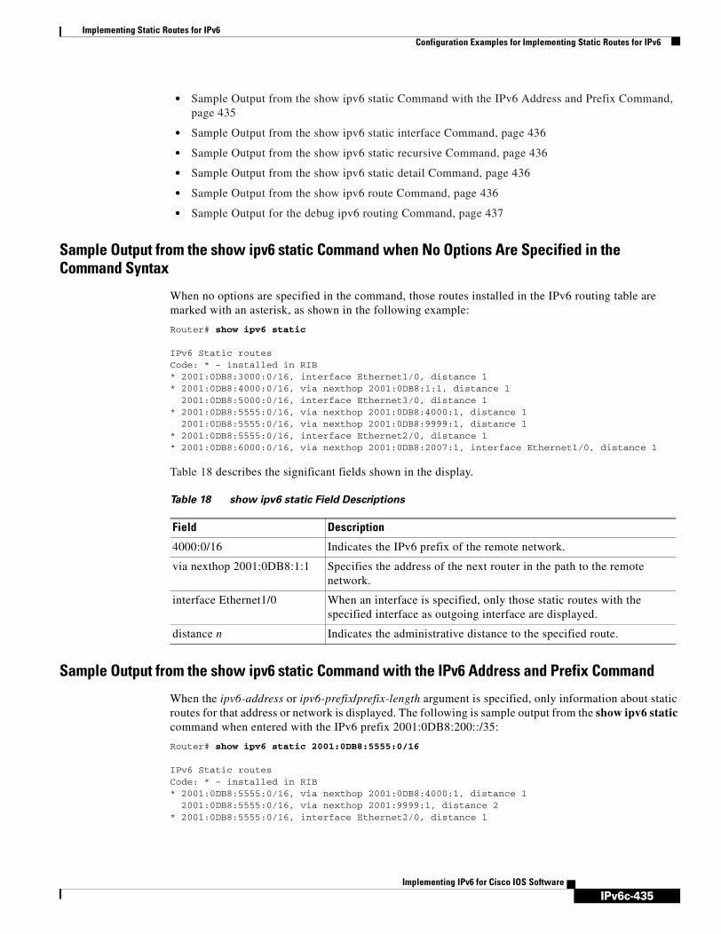
IPv6c-435
Implementing Static Routes for IPv6Configuration Examples for Implementing Static Routes for IPv6
Implementing IPv6 for Cisco IOS Software
• Sample Output from the show ipv6 static Command with the IPv6 Address and Prefix Command, page 435
• Sample Output from the show ipv6 static interface Command, page 436
• Sample Output from the show ipv6 static recursive Command, page 436
• Sample Output from the show ipv6 static detail Command, page 436
• Sample Output from the show ipv6 route Command, page 436
• Sample Output for the debug ipv6 routing Command, page 437
Sample Output from the show ipv6 static Command when No Options Are Specified in the Command Syntax
When no options are specified in the command, those routes installed in the IPv6 routing table are marked with an asterisk, as shown in the following example:
Router# show ipv6 static
IPv6 Static routesCode: * - installed in RIB* 2001:0DB8:3000:0/16, interface Ethernet1/0, distance 1* 2001:0DB8:4000:0/16, via nexthop 2001:0DB8:1:1, distance 1
2001:0DB8:5000:0/16, interface Ethernet3/0, distance 1* 2001:0DB8:5555:0/16, via nexthop 2001:0DB8:4000:1, distance 1
2001:0DB8:5555:0/16, via nexthop 2001:0DB8:9999:1, distance 1* 2001:0DB8:5555:0/16, interface Ethernet2/0, distance 1* 2001:0DB8:6000:0/16, via nexthop 2001:0DB8:2007:1, interface Ethernet1/0, distance 1
Table 18 describes the significant fields shown in the display.
Sample Output from the show ipv6 static Command with the IPv6 Address and Prefix Command
When the ipv6-address or ipv6-prefix/prefix-length argument is specified, only information about static routes for that address or network is displayed. The following is sample output from the show ipv6 static command when entered with the IPv6 prefix 2001:0DB8:200::/35:
Router# show ipv6 static 2001:0DB8:5555:0/16
IPv6 Static routesCode: * - installed in RIB* 2001:0DB8:5555:0/16, via nexthop 2001:0DB8:4000:1, distance 1
2001:0DB8:5555:0/16, via nexthop 2001:9999:1, distance 2* 2001:0DB8:5555:0/16, interface Ethernet2/0, distance 1
Table 18 show ipv6 static Field Descriptions
Field Description
4000:0/16 Indicates the IPv6 prefix of the remote network.
via nexthop 2001:0DB8:1:1 Specifies the address of the next router in the path to the remote network.
interface Ethernet1/0 When an interface is specified, only those static routes with the specified interface as outgoing interface are displayed.
distance n Indicates the administrative distance to the specified route.

IPv6c-436
Implementing Static Routes for IPv6Configuration Examples for Implementing Static Routes for IPv6
Implementing IPv6 for Cisco IOS Software
Sample Output from the show ipv6 static interface Command
When an interface is supplied, only those static routes with the specified interface as outgoing interface are displayed. The interface keyword may be used with or without the IPv6 address and prefix specified in the show ipv6 static command.
Router# show ipv6 static interface ethernet3/0
IPv6 Static routesCode: * - installed in RIB 2001:0DB8:5000:)/16, interface Ethernet3/0, distance 1
Sample Output from the show ipv6 static recursive Command
When the recursive keyword is specified in the show ipv6 static command, only recursive static routes are displayed. The recursive keyword is mutually exclusive with the interface keyword, but it may be used with or without the IPv6 prefix included in the command syntax.
Router# show ipv6 static recursive
IPv6 Static routesCode: * - installed in RIB* 2001:0DB8:4000:0/16, via nexthop 2001:0DB8:1:1, distance 1* 2001:0DB8:5555:0/16, via nexthop 2001:0DB8:4000:1, distance 2
2001:0DB8:5555:0/16, via nexthop 2001:0DB8:9999:1, distance 3
Sample Output from the show ipv6 static detail Command
When the detail keyword is specified, the following additional information is also displayed:
• For valid recursive routes, the output path set, and maximum resolution depth
• For invalid recursive routes, the reason why the route is not valid.
• For invalid direct or fully-specified routes, the reason why the route is not valid.
Router# show ipv6 static detail
IPv6 Static routesCode: * - installed in RIB* 2001:0DB8:3000:0/16, interface Ethernet1/0, distance 1* 2001:0DB8:4000:0/16, via nexthop 2001:0DB8:2001:1, distance 1 Resolves to 1 paths (max depth 1) via Ethernet1/0
2001:0DB8:5000:0/16, interface Ethernet3/0, distance 1 Interface is down* 2001:0DB8:5555:0/16, via nexthop 2001:0DB8:4000:1, distance 1 Resolves to 1 paths (max depth 2) via Ethernet1/0
2001:0DB8:5555:0/16, via nexthop 2001:0DB8:9999:1, distance 1 Route does not fully resolve* 2001:0DB8:5555:0/16, interface Ethernet2/0, distance 1* 2001:0DB8:6000:0/16, via nexthop 2001:0DB8:2007:1, interface Ethernet1/0, distance 1
Sample Output from the show ipv6 route Command
In the following example, the show ipv6 route command is used to verify the configuration of a static route through a point-to-point interface:
Router# show ipv6 route

IPv6c-437
Implementing Static Routes for IPv6Where to Go Next
Implementing IPv6 for Cisco IOS Software
IPv6 Routing Table - 9 entriesCodes: C - Connected, L - Local, S - Static, R - RIP, B - BGP U - Per-user Static route I1 - ISIS L1, I2 - ISIS L2, IA - ISIS interarea O - OSPF intra, OI - OSPF inter, OE1 - OSPF ext 1, OE2 - OSPF ext 2S 2001:0DB8::/32 [1/0] via ::, Serial2/0
In the following example, the show ipv6 route command is used to verify the configuration of a static route on a multiaccess interface. An IPv6 link-local address—FE80::1—is the next hop router.
Router# show ipv6 route
IPv6 Routing Table - 11 entriesCodes: C - Connected, L - Local, S - Static, R - RIP, B - BGP U - Per-user Static route I1 - ISIS L1, I2 - ISIS L2, IA - ISIS interarea O - OSPF intra, OI - OSPF inter, OE1 - OSPF ext 1, OE2 - OSPF ext 2S 2001:0DB8::/32 [1/0] via FE80::1, Ethernet0/0
To display all static routes in the IPv6 routing table, use the show ipv6 route static command is used with static as the value of the protocol argument:
Router# show ipv6 route static
IPv6 Routing Table - 330 entriesCodes: C - Connected, L - Local, S - Static, R - RIP, B - BGP U - Per-user Static route I1 - ISIS L1, I2 - ISIS L2, IA - ISIS interareaS 2001:0DB8::/32 [1/0] via ::, Tunnel0S 3FFE:C00:8011::/48 [1/0] via ::, Null0S ::/0 [254/0] via 2001:0DB8:2002:806B, Null
Sample Output for the debug ipv6 routing Command
In the following example, the debug ipv6 routing command is used to verify the installation of a floating static route into the IPv6 routing table when an IPv6 RIP route is deleted. The floating static IPv6 route was previously configured with an administrative distance value of 130. The backup route was added as a floating static route because RIP routes have a default administrative distance of 120, and the RIP route should be the preferred route. When the RIP route is deleted, the floating static route is installed in the IPv6 routing table.
Router# debug ipv6 routing
*Oct 10 18:28:00.847: IPv6RT0: rip two, Delete 2001:0DB8::/32 from table*Oct 10 18:28:00.847: IPv6RT0: static, Backup call for 2001:0DB8::/32*Oct 10 18:28:00.847: IPv6RT0: static, Add 2001:0DB8::/32 to table*Oct 10 18:28:00.847: IPv6RT0: static, Adding next-hop :: over Serial2/0 for 2001:0DB8::/32, [130/0]
Where to Go NextIf you want to implement routing protocols, refer to the Implementing RIP for IPv6, Implementing IS-IS for IPv6, Implementing OSPF for IPv6, or Implementing Multiprotocol BGP for IPv6 module.

IPv6c-438
Implementing Static Routes for IPv6Additional References
Implementing IPv6 for Cisco IOS Software
Additional ReferencesFor additional information related to configuring static IPv6 routes, see the following sections:
• Related Documents, page 438
• Standards, page 438
• MIBs, page 438
• RFCs, page 439
• Technical Assistance, page 439
Related Documents
Standards
MIBs
Related Topic Document Title
IP static route configuration “Configuring IP Routing Protocol-Independent Features” chapter in the Cisco IOS IP Configuration Guide, Release 12.4
IP static route commands: complete command syntax, command mode, defaults, usage guidelines, and examples
Cisco IOS IP Command Reference, Volume 2 of 3: Routing Protocols, Release 12.4
IPv6 supported feature list Start Here: Cisco IOS Software Release Specifics for IPv6 Features
IPv6 commands: complete command syntax, command mode, defaults, usage guidelines, and examples
IPv6 for Cisco IOS Command Reference
IPv4 configuration and command reference information
http://www.cisco.com/univercd/cc/td/doc/product/software/ios123/123cgcr/index.htm
Standards Title
No new or modified standards are supported by this feature, and support for existing standards has not been modified by this feature.
—
MIBs MIBs Link
No new or modified MIBs are supported by this feature, and support for existing MIBs has not been modified by this feature.
To locate and download MIBs for selected platforms, Cisco IOS releases, and feature sets, use Cisco MIB Locator found at the following URL:
http://www.cisco.com/go/mibs

IPv6c-439
Implementing Static Routes for IPv6Additional References
Implementing IPv6 for Cisco IOS Software
RFCs
Technical Assistance
RFCs Title
No new or modified RFCs are supported by this feature, and support for existing RFCs has not been modified by this feature.
—
Description Link
The Cisco Technical Support website contains thousands of pages of searchable technical content, including links to products, technologies, solutions, technical tips, and tools. Registered Cisco.com users can log in from this page to access even more content.
http://www.cisco.com/techsupport

IPv6c-440
Implementing Static Routes for IPv6Additional References
Implementing IPv6 for Cisco IOS Software

IPv6c-441Implementing IPv6 for Cisco IOS Software
Implementing ADSL and Deploying Dial Access for IPv6
This module describes the implementation of prefix pools and per-user Remote Access Dial-In User Service (RADIUS) attributes in IPv6. It also describes the deployment of IPv6 in Digital Subscriber Line (DSL) and dial-access environments. Asymmetric Digital Subscriber Line (ADSL) and dial deployment provide the extensions that make large-scale access possible for IPv6 environments, including IPv6 RADIUS attributes, stateless address configuration on Point-to-Point Protocol (PPP) links, per-user static routes, and access control lists (ACLs).
Finding Support Information for Platforms and Cisco IOS Software Images
Use Cisco Feature Navigator to find information about platform support and Cisco IOS software image support. Access Cisco Feature Navigator at http://www.cisco.com/go/fn. You must have an account on Cisco.com. If you do not have an account or have forgotten your username or password, click Cancel at the login dialog box and follow the instructions that appear.
Contents• Restrictions for Implementing ADSL and Deploying Dial Access for IPv6, page 442
• Information About Implementing ADSL and Deploying Dial Access for IPv6, page 442
• How to Configure ADSL and Deploy Dial Access in IPv6, page 446
• Configuration Examples for Implementing ADSL and Deploying Dial Access for IPv6, page 454
• Where to Go Next, page 455
• Additional References, page 455
Prerequisites for Implementing ADSL and Dial Access for IPv6Table 19 identifies the earliest release for each early-deployment train in which each feature became available.

IPv6c-442
Implementing ADSL and Deploying Dial Access for IPv6Restrictions for Implementing ADSL and Deploying Dial Access for IPv6
Implementing IPv6 for Cisco IOS Software
Restrictions for Implementing ADSL and Deploying Dial Access for IPv6
ADSL and Dial Deployment is available for interfaces with PPP encapsulation enabled, including PPP over ATM (PPPoA), PPP over Ethernet (PPPoE), PPP over async, and PPP over ISDN.
Information About Implementing ADSL and Deploying Dial Access for IPv6
To implement ADSL and deploy dial access for IPv6, you need to understand the following concepts:
• Address Assignment for IPv6, page 442
• AAA Attributes for IPv6, page 443
Address Assignment for IPv6A Cisco router configured with IPv6 will advertise its IPv6 prefixes on one or more interfaces, allowing IPv6 clients to automatically configure their addresses. In IPv6, address assignment is performed at the network layer, in contrast to IPv4 where a number of functions are handled in the PPP layer. The only function handled in IPv6 Control Protocol (IPv6CP) is the negotiation of a unique interface identifier. Everything else, including DNS server discovery, is done within the IPv6 protocol itself.
Contrary to IPv4 address assignment, an IPv6 user will be assigned a prefix, not a single address. Typically the Internet Service Provider (ISP) assigns a 64- or 48-bit prefix.
In the IPv6 world, Internet service providers (ISPs) assign long-lived prefixes to users, which has some impact on the routing system. In typical IPv4 environments, each network access server (NAS) has a pool of 24-bit addresses and users get addresses from this pool when dialing in. If a user dials another POP or is connected to another NAS at the same POP, a different IPv4 address is assigned.
Table 19 Minimum Required Cisco IOS Release
FeatureMinimum Required Cisco IOS Release by Release Train
Enhanced IPv6 features for ADSL and dial deployment
12.2(13)T, 12.3, 12.3(2)T, 12.4, 12.4(2)T
AAA IPv6 attribute support 12.3(4)T, 12.4, 12.4(2)T
PPPoA 12.2(13)T, 12.3, 12.3(2)T, 12.4, 12.4(2)T
PPPoE 12.2(13)T, 12.3, 12.3(2)T, 12.4, 12.4(2)T
Prefix pools 12.2(13)T, 12.3, 12.3(2)T, 12.4, 12.4(2)T
AAA support for Cisco VSA IPv6 attributes 12.2(13)T, 12.3, 12.3(2)T, 12.4, 12.4(2)T
AAA support for RFC 3162 IPv6 RADIUS attributes
12.3(4)T, 12.4, 12.4(2)T
DHCP for IPv6 prefix delegation via AAA 12.3(14)T, 12.2(18)SXE, 12.4, 12.4(2)T

IPv6c-443
Implementing ADSL and Deploying Dial Access for IPv6Information About Implementing ADSL and Deploying Dial Access for IPv6
Implementing IPv6 for Cisco IOS Software
Addresses for IPv6 are assigned by two different methods.
• Stateless Address Autoconfiguration, page 443
• Prefix Delegation, page 443
Stateless Address Autoconfiguration
Assigning addresses using the stateless address autoconfiguration method can only be used to assign 64-bit prefixes. Each user is assigned a 64-bit prefix, which is advertised to the user in a router advertisement (RA). All addresses are automatically configured based on the assigned prefix.
A typical scenario is to assign a separate 64-bit prefix per user; however, users can also be assigned a prefix from a shared pool of addresses. Using the shared limits addresses to only one address per user.
This solution works best for the cases where the customer provider edge router (CPE) is a single PC or is limited to only one subnet. If the user has multiple subnets, Layer 2 (L2) bridging, multilink subnets or proxy RA can be used. The prefix advertised in the RA can come from an authorization, authentication, and accounting (AAA) server, which also provides the prefix attribute, can be manually configured, or can be allocated from a prefix pool.
The Framed-Interface-Id AAA attribute influences the choice of interface identifier for peers and, in combination with the prefix, the complete IPv6 address can be determined.
Prefix Delegation
Prefix delegation uses Dynamic Host Configuration Protocol (DHCP). When the user requests a prefix from the prefix delegator, typically the NAS, the prefix is allocated as described in the “Stateless Address Autoconfiguration” section on page 443.
An IPv6 prefix delegating router selects IPv6 prefixes to be assigned to a requesting router upon receiving a request from the client. The delegating router might select prefixes for a requesting router in the following ways:
• Static assignment based on subscription to an ISP
• Dynamic assignment from a pool of available prefixes
• Selection based on an external authority such as a RADIUS server using the Framed-IPv6-Prefix attribute (see the “Framed-IPv6-Prefix” section on page 444).
DHCP SIP Server Options
Two DHCP for IPv6 Session Initiation Protocol (SIP) server options describe a local outbound SIP proxy: one carries a list of domain names, the other a list of IPv6 addresses. These two options can be configured in a DHCPv6 configuration pool.
AAA Attributes for IPv6Vendor-specific attributes (VSAs) have been developed to support AAA for IPv6. The Cisco VSAs are inacl, outacl, route, and prefix.
Prefix pools and pool names are configurable through AAA.
The following RADIUS attributes as described in RFC 3162 are supported for IPv6:
• Framed-Interface-Id

IPv6c-444
Implementing ADSL and Deploying Dial Access for IPv6Information About Implementing ADSL and Deploying Dial Access for IPv6
Implementing IPv6 for Cisco IOS Software
• Framed-IPv6-Prefix
• Login-IPv6-Host
• Framed-IPv6-Route
• Framed-IPv6-Pool
These attributes can be configured on a RADIUS server and downloaded to access servers where they can be applied to access connections.
AAA attributes are described in the following sections:
• RADIUS Per-User Attributes for Virtual Access in IPv6 Environments, page 444
• IPv6 Prefix Pools, page 446
Prerequisites for Using AAA Attributes for IPv6
The AAA attributes for IPv6 are compliant with RFC 3162 and require a RADIUS server capable of supporting RFC 3162.
RADIUS Per-User Attributes for Virtual Access in IPv6 Environments
The following IPv6 attributes for RADIUS attribute-value (AV) pairs are supported for virtual access:
• Framed-Interface-Id, page 444
• Framed-IPv6-Prefix, page 444
• Login-IPv6-Host, page 445
• Framed-IPv6-Route, page 445
• Framed-IPv6-Pool, page 445
• IPv6 Route, page 445
• IPv6 ACL, page 445
• IPv6 Prefix#, page 445
• IPv6 Pool, page 446
Apart from the new IPv6 prefix and IPv6 pool attributes, these are all existing Cisco VSAs extended to support the IPv6 protocol.
Framed-Interface-Id
The Framed-Interface-Id attribute indicates the IPv6 interface identifier to be configured. This per-user attribute is used during the IPv6CP negotiations and may be used in access-accept packets. If the Interface-Identifier IPv6CP option has been successfully negotiated, this attribute must be included in an Acc-0Request packet as a hint by the NAS to the server that it would prefer that value.
Framed-IPv6-Prefix
The Framed-IPv6-Prefix attribute performs the same function as the Cisco VSA: It is used for virtual access only and indicates an IPv6 prefix (and corresponding route) to be configured. This attribute is a per-user attribute and lets the user specify which prefixes to advertise in Neighbor Discovery Router Advertisement messages. The Framed-IPv6-Prefix attribute may be used in access-accept packets and can appear multiple times. The NAS will create a corresponding route for the prefix.

IPv6c-445
Implementing ADSL and Deploying Dial Access for IPv6Information About Implementing ADSL and Deploying Dial Access for IPv6
Implementing IPv6 for Cisco IOS Software
To use this attribute for DHCP for IPv6 prefix delegation, create a profile for the same user on the RADIUS server. The user name associated with the second profile has the suffix “-dhcpv6.”
The Framed-IPv6-Prefix attribute in the two profiles is treated differently. If a NAS needs both to send a prefix in router advertisements (RAs) and delegate a prefix to a remote user’s network, the prefix for RA is placed in the Framed-IPv6-Prefix attribute in the user’s regular profile, and the prefix used for prefix delegation is placed in the attribute in the user’s separate profile.
Login-IPv6-Host
The Login-IPv6-Host attribute is a per-user attribute that indicates the IPv6 system with which to connect the user when the Login-Service attribute is included.
Framed-IPv6-Route
The Framed-IPv6-Route attribute performs the same function as the Cisco VSA: It is a per-user attribute that provides routing information to be configured for the user on the NAS. This attribute is a string attribute and is specified using the ipv6 route command.
Framed-IPv6-Pool
The IPv6-Pool attribute is a per-user attribute that contains the name of an assigned pool that should be used to assign an IPv6 prefix for the user. This pool should either be defined locally on the router or defined on a RADIUS server from which pools can be downloaded.
IPv6 Route
The IPv6 route attribute allows you to specify a per-user static route. A static route is appropriate when the Cisco IOS software cannot dynamically build a route to the destination. See the description of the ipv6 route command for more information about building static routes.
The following example shows the IPv6 route attribute used to define a static route.
cisco-avpair = "ipv6:route#1=2001:0DB8:cc00:1::/48",cisco-avpair = "ipv6:route#2=2001::0DB8:cc00:2::/48",
IPv6 ACL
You can specify a complete IPv6 access list. The unique name of the access list is generated automatically. The access list is removed when its user logs out. The previous access list on the interface is reapplied.
The inacl and outacl attributes allow you to a specific existing access list configured on the router. The following example shows ACL number 1 specified as the access list:
cisco-avpair = "ipv6:inacl#1=permit 2001:0DB8:cc00:1::/48",cisco-avpair = "ipv6:outacl#1=deny 2001:0DB8::/10",
IPv6 Prefix#
The IPv6 prefix# attribute lets you indicate which prefixes to advertise in Neighbor Discovery Router Advertisement messages. When the prefix# attribute is used, a corresponding route (marked as a per-user static route) is installed in the routing information base (RIB) tables for the given prefix.
cisco-avpair = "ipv6:prefix#1=2001:0db8:/64",cisco-avpair = "ipv6:prefix#2=2001:0db8:/64",

IPv6c-446
Implementing ADSL and Deploying Dial Access for IPv6How to Configure ADSL and Deploy Dial Access in IPv6
Implementing IPv6 for Cisco IOS Software
IPv6 Pool
For RADIUS authentication, the IPv6 pool attribute extends the IPv4 address pool attributed to support the IPv6 protocol. It specifies the name of a local pool on the NAS from which to get the prefix and is used whenever the service is configured as PPP and whenever the protocol is specified as IPv6. Note that the address pool works in conjunction with local pooling. It specifies the name of the local pool that has been preconfigured on the NAS.
IPv6 Prefix Pools
The function of prefix pools in IPv6 is similar to that of address pools in IPv4. The main difference is that IPv6 assigns prefixes rather than single addresses.
As for IPv4, a pool or a pool definition can be configured locally or it can be retrieved from an AAA server. Overlapping membership between pools is not permitted.
Once a pool is configured, it cannot be changed. If you change the configuration, the pool will be removed and re-created. All prefixes previously allocated will be freed.
Prefix pools can be defined so that each user is allocated a 64-bit prefix or so that a single prefix is shared among several users. In a shared prefix pool, each user may receive only one address from the pool.
How to Configure ADSL and Deploy Dial Access in IPv6The configuration guidelines contained in this section show how to configure ADSL and dial access in IPv6 environments.
• Configuring the NAS, page 446 (required)
• Configuring the Remote CE Router, page 449 (required)
• Configuring the DHCP for IPv6 Server to Obtain Prefixes from RADIUS Servers, page 452 (optional)
• Configuring DHCP for IPv6 AAA and SIP Options, page 453 (optional)
Configuring the NASThe first step in setting up dial access is to configure the NAS. All of the dialer groups, access lists, and routes are known to the NAS. This task shows how to configure the NAS to implement ADSL and deploy dial access for IPv6 environments.
SUMMARY STEPS
1. enable
2. configure terminal
3. hostname name
4. aaa new-model
5. aaa authentication ppp {default | list-name} method1 [method2...]
6. aaa authorization configuration default {radius | tacacs+}

IPv6c-447
Implementing ADSL and Deploying Dial Access for IPv6How to Configure ADSL and Deploy Dial Access in IPv6
Implementing IPv6 for Cisco IOS Software
7. show ipv6 route [ipv6-address | ipv6-prefix/prefix-length | protocol | interface-type interface-number]
8. virtual-profile virtual-template number
9. interface serial controller-number:timeslot
10. encapsulation encapsulation-type
11. exit
12. dialer-group group-number
13. ppp authentication {protocol1 [protocol2...]} [if-needed] [list-name | default] [callin] [one-time] [optional]
14. interface virtual-template number
15. ipv6 enable
16. dialer-list dialer-group protocol protocol-name {permit | deny | list access-list-number | access-group}
17. radius-server host {hostname | ip-address} [auth-port port-number] [acct-port port-number] [timeout seconds] [retransmit retries] [key string] [alias{hostname | ip-address}]
DETAILED STEPS
Command or Action Purpose
Step 1 enable
Example:Router> enable
Enables privileged EXEC mode.
• Enter your password if prompted.
Step 2 configure terminal
Example:Router# configure terminal
Enters global configuration mode.
Step 3 hostname name
Example:Router(config)# hostname cust1-53a
Specifies the host name for the network server.
Step 4 aaa new-model
Example:Router(config)# aaa new-model
Enables the AAA server.
Step 5 aaa authentication ppp {default | list-name} method1 [method2...]
Example:Router(config)# aaa authentication ppp default if-needed group radius
Specifies one or more AAA authentication methods for use on serial interfaces that are running PPP.

IPv6c-448
Implementing ADSL and Deploying Dial Access for IPv6How to Configure ADSL and Deploy Dial Access in IPv6
Implementing IPv6 for Cisco IOS Software
Step 6 aaa authorization configuration default {radius | tacacs+}
Example:Router(config)# aaa authorization network default group radius
Downloads configuration information from the AAA server.
Step 7 show ipv6 route [ipv6-address | ipv6-prefix/prefix-length | protocol | interface-type interface-number]
Example:Router(config)# show ipv6 route
Shows the routes installed by the previous commands.
Step 8 virtual-profile virtual-template number
Example:Router(config)# virtual-profile virtual-template 1
Enables virtual profiles by virtual interface template.
Step 9 interface serial controller-number:timeslot
Example:Router(config)# interface Serial0:15
Specifies a serial interface created on a channelized E1 or channelized T1 controller (for ISDN PRI, channel-associated signaling, or robbed-bit signaling).
Step 10 encapsulation encapsulation-type
Example:Router(config-if)# encapsulation ppp
Sets the encapsulation method used by the interface.
Step 11 exit
Example:Router(config-if)# exit
Returns to global configuration mode.
Step 12 dialer-group group-number
Example:Router(config)# dialer-group 1
Control access by configuring an interface to belong to a specific dialing group.
Step 13 ppp authentication {protocol1 [protocol2...]} [if-needed] [list-name | default] [callin] [one-time] [optional]
Example:Router(config)# ppp authentication chap
Enables Challenge Handshake Authentication Protocol (CHAP) or Password Authentication Protocol (PAP) or both and specifies the order in which CHAP and PAP authentication are selected on the interface.
Step 14 interface virtual-template number
Example:Router(config)# interface virtual-template1
Creates a virtual template interface that can be configured and applied dynamically in creating virtual access interfaces.
Command or Action Purpose

IPv6c-449
Implementing ADSL and Deploying Dial Access for IPv6How to Configure ADSL and Deploy Dial Access in IPv6
Implementing IPv6 for Cisco IOS Software
Troubleshooting Tips
Verify that the access list is installed correctly before proceeding with the next task. Use the show ipv6 access-list and show ipv6 interface commands.
What to Do Next
Configure the remote customer edge (CE) router as described in the “Configuring the Remote CE Router” section on page 449
Configuring the Remote CE RouterThe following task describes how to configure each remote CE router.
SUMMARY STEPS
1. enable
2. configure terminal
3. hostname name
4. interface bri number.subinterface-number [multipoint | point-to-point]
5. encapsulation encapsulation-type
6. ipv6 address autoconfig
7. isdn switch-type switch-type
8. ppp authentication {protocol1 [protocol2...]} [if-needed] [list-name | default] [callin] [one-time]
Step 15 ipv6 enable
Example:Router(config)# ipv6 enable
Enables IPv6 processing on an interface that has not been configured with an explicit IPv6 address.
Step 16 dialer-list dialer-group protocol protocol-name {permit | deny | list access-list-number | access-group}
Example:Router(config)# dialer-list 1 protocol ipv6 permit
Defines a dial-on-demand routing (DDR) dialer list for dialing by protocol or by a combination of a protocol and a previously defined access list.
Step 17 radius-server host {hostname | ip-address} [auth-port port-number] [acct-port port-number] [timeout seconds] [retransmitretries] [key string] [alias{hostname | ip-address}]
Example:Router(config)# radius-server host 172.17.250.8 auth-port 1812 acct-port 1813 key testing123
Specifies a RADIUS server host.
Command or Action Purpose

IPv6c-450
Implementing ADSL and Deploying Dial Access for IPv6How to Configure ADSL and Deploy Dial Access in IPv6
Implementing IPv6 for Cisco IOS Software
9. ppp multilink [bap | required]
10. exit
11. dialer-list dialer-group protocol protocol-name {permit | deny | list access-list-number | access-group}
12. ipv6 route ipv6-prefix/prefix-length {ipv6-address | interface-type interface-number [ipv6-address]} [administrative-distance] [administrative-multicast-distance | unicast | multicast] [tag tag]
DETAILED STEPS
Command or Action Purpose
Step 1 enable
Example:Router> enable
Enables privileged EXEC mode.
• Enter your password if prompted.
Step 2 configure terminal
Example:Router# configure terminal
Enters global configuration mode.
Step 3 hostname name
Example:Router(config)# hostname cust1-36a
Specifies the host name for the network server.
Step 4 interface bri number.subinterface-number [multipoint | point-to-point]
Example:Router(config)# interface BRI1/0
Configures a BRI interface and enters interface configuration mode.
Step 5 encapsulation encapsulation-type
Example:Router(config-if)# encapsulation ppp
Sets the encapsulation method used by the interface.
Step 6 ipv6 address autoconfig
Example:Router(config-if)# ipv6 address autoconfig
Indicates that the IPv6 address will be generated automatically.
Step 7 isdn switch-type switch-type
Example:Router(config-if)# isdn switch-type basic-net3
Specifies the central office switch type on the ISDN interface.

IPv6c-451
Implementing ADSL and Deploying Dial Access for IPv6How to Configure ADSL and Deploy Dial Access in IPv6
Implementing IPv6 for Cisco IOS Software
What to Do Next
Once you have configured the NAS and CE router, configure RADIUS to establish the AV pairs for callback. Callback allows remote network users to dial in to the NAS without being charged. When callback is required, the NAS hangs up the current call and dials the caller back. When the NAS performs the callback, only information for the outgoing connection is applied. The rest of the attributes from the preauthentication access-accept message are discarded.
The following example shows a RADIUS profile configuration for a local campus:
campus1 Auth-Type = Local, Password = "mypassword" User-Service-Type = Framed-User, Framed-Protocol = PPP, cisco-avpair = "ipv6:inacl#1=permit dead::/64 any", cisco-avpair = "ipv6:route=dead::/64", cisco-avpair = "ipv6:route=cafe::/64", cisco-avpair = "ipv6:prefix=dead::/64 0 0 onlink autoconfig", cisco-avpair = "ipv6:prefix=cafe::/64 0 0 onlink autoconfig", cisco-avpair = "ip:route=10.0.0.0 255.0.0.0",
Step 8 ppp authentication {protocol1 [protocol2...]} [if-needed] [list-name | default] [callin] [one-time]
Example:Router(config-if)# ppp authentication chap optional
Enables Challenge Handshake Authentication Protocol (CHAP) or Password Authentication Protocol (PAP) or both and specifies the order in which CHAP and PAP authentication are selected on the interface.
Step 9 ppp multilink [bap | required]
Example:Router(config-if)# ppp multilink
Enables Multilink PPP (MLP) on an interface and, optionally, enables Bandwidth Allocation Control Protocol (BACP) and Bandwidth Allocation Protocol (BAP) for dynamic bandwidth allocation.
Step 10 exit
Example:Router(config-if)# exit
Exits interface configuration mode and returns to global configuration mode.
Step 11 dialer-list dialer-group protocol protocol-name {permit | deny | list access-list-number | access-group}
Example:Router(config)# dialer-list 1 protocol ipv6 permit
Defines a dial-on-demand routing (DDR) dialer list for dialing by protocol or by a combination of a protocol and a previously defined access list.
Step 12 ipv6 route ipv6-prefix/prefix-length {ipv6-address | interface-type interface-number [ipv6-address]} [administrative-distance] [administrative-multicast-distance | unicast | multicast] [tag tag]
Example:Router(config)# ipv6 route 2001:0db8:1/128 BRI1/0
Establishes static IPv6 routes. Use one command for each route.
Command or Action Purpose

IPv6c-452
Implementing ADSL and Deploying Dial Access for IPv6How to Configure ADSL and Deploy Dial Access in IPv6
Implementing IPv6 for Cisco IOS Software
The RADIUS AV pairs for IPv6 are described in RADIUS Per-User Attributes for Virtual Access in IPv6 Environments, page 444.
Refer to the Cisco IOS Security Configuration Guide for detailed information about configuring RADIUS.
Configuring the DHCP for IPv6 Server to Obtain Prefixes from RADIUS ServersThe following task describes how to configure the DHCP for IPv6 server to obtain prefixes from RADIUS servers.
Prerequisites
Before you perform this task, you must configure the AAA client and PPP on the router.
SUMMARY STEPS
1. enable
2. configure terminal
3. interface type number
4. ipv6 nd prefix framed-ipv6-prefix
DETAILED STEPS
Command or Action Purpose
Step 1 enable
Example:Router> enable
Enables privileged EXEC mode.
• Enter your password if prompted.
Step 2 configure terminal
Example:Router# configure terminal
Enters global configuration mode.
Step 3 interface type number
Example:Router(config)# interface ethernet 0/0
Specifies an interface type and number, and places the router in interface configuration mode.
Step 4 ipv6 nd prefix framed-ipv6-prefix
Example:Router(config-if)# ipv6 nd prefix framed-ipv6-prefix
Adds the prefix in a received RADIUS framed IPv6 prefix attribute to the interface’s neighbor discovery prefix queue.
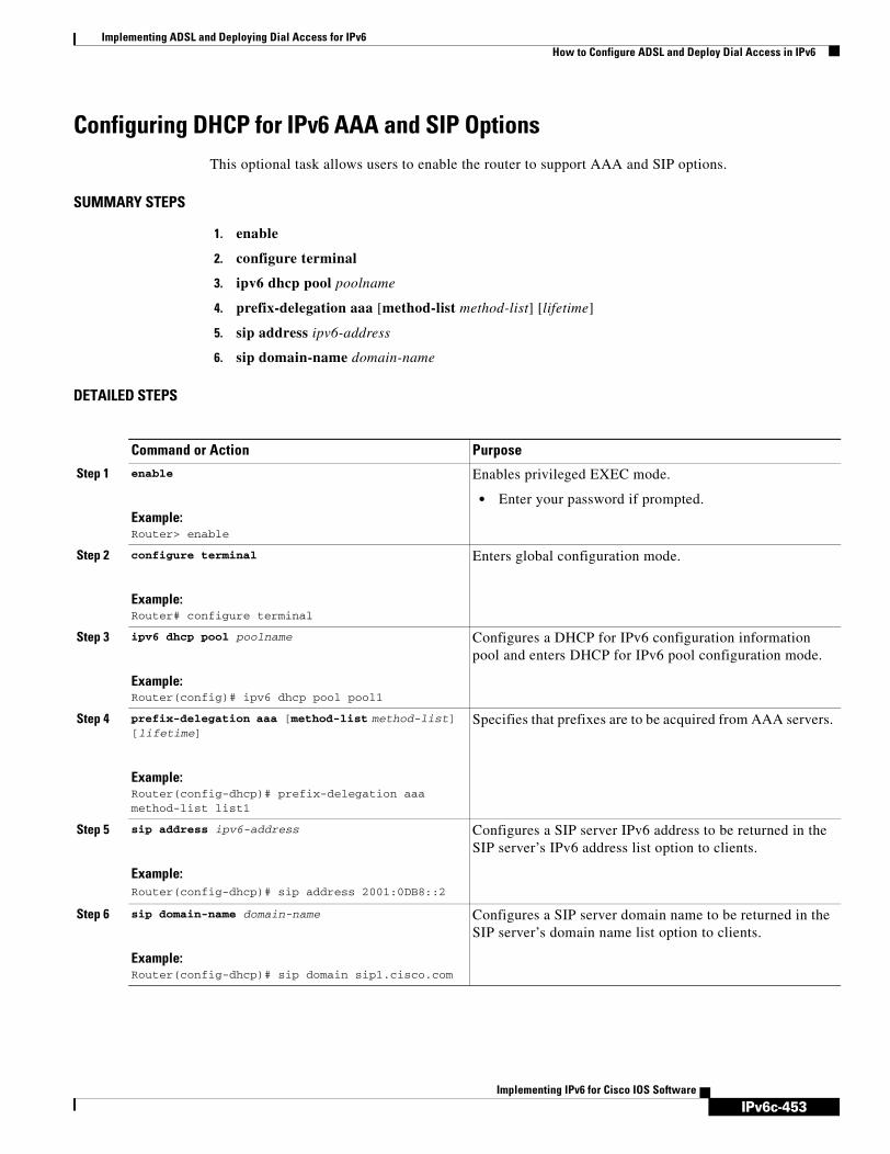
IPv6c-453
Implementing ADSL and Deploying Dial Access for IPv6How to Configure ADSL and Deploy Dial Access in IPv6
Implementing IPv6 for Cisco IOS Software
Configuring DHCP for IPv6 AAA and SIP OptionsThis optional task allows users to enable the router to support AAA and SIP options.
SUMMARY STEPS
1. enable
2. configure terminal
3. ipv6 dhcp pool poolname
4. prefix-delegation aaa [method-list method-list] [lifetime]
5. sip address ipv6-address
6. sip domain-name domain-name
DETAILED STEPS
Command or Action Purpose
Step 1 enable
Example:Router> enable
Enables privileged EXEC mode.
• Enter your password if prompted.
Step 2 configure terminal
Example:Router# configure terminal
Enters global configuration mode.
Step 3 ipv6 dhcp pool poolname
Example:Router(config)# ipv6 dhcp pool pool1
Configures a DHCP for IPv6 configuration information pool and enters DHCP for IPv6 pool configuration mode.
Step 4 prefix-delegation aaa [method-list method-list] [lifetime]
Example:Router(config-dhcp)# prefix-delegation aaa method-list list1
Specifies that prefixes are to be acquired from AAA servers.
Step 5 sip address ipv6-address
Example:Router(config-dhcp)# sip address 2001:0DB8::2
Configures a SIP server IPv6 address to be returned in the SIP server’s IPv6 address list option to clients.
Step 6 sip domain-name domain-name
Example:Router(config-dhcp)# sip domain sip1.cisco.com
Configures a SIP server domain name to be returned in the SIP server’s domain name list option to clients.

IPv6c-454
Implementing ADSL and Deploying Dial Access for IPv6Configuration Examples for Implementing ADSL and Deploying Dial Access for IPv6
Implementing IPv6 for Cisco IOS Software
Configuration Examples for Implementing ADSL and Deploying Dial Access for IPv6
This section provides the following configuration example:
• Implementing ADSL and Deploying Dial Access for IPv6 Example, page 454
Implementing ADSL and Deploying Dial Access for IPv6 ExampleThis example shows a typical configuration for ADSL and dial access. The following three separate configurations are required:
• NAS Configuration
• Remote CE Router Configuration
• RADIUS Configuration
NAS Configuration
This configuration for the ISP NAS shows the configuration that supports access from the remote CE router.
hostname cust1-53a aaa new-model aaa authentication ppp default if-needed group radius aaa authorization network default group radius virtual-profile virtual-template 1 interface Serial0:15 encapsulation ppp dialer-group 1 ppp authentication chap ! interface Virtual-Template1 ipv6 enable ! dialer-list 1 protocol ipv6 permit radius-server host 172.17.250.8 auth-port 1812 acct-port 1813 key testing123
Remote CE Router Configuration
This configuration for the remote customer edge router shows PPP encapsulation and IPv6 routes defined.
hostname cust-36a interface BRI1/0 encapsulation ppp ipv6 enable isdn switch-type basic-net3 ppp authentication chap optional ppp multilink ! dialer-list 1 protocol ipv6 permit ipv6 route 2001:0DB8:1/128 BRI1/0 ipv6 route ::/0 2001:0db8:1
RADIUS Configuration
This RADIUS configuration shows the definition of AV pairs to establish the static routes.
campus1 Auth-Type = Local, Password = "mypassword"

IPv6c-455
Implementing ADSL and Deploying Dial Access for IPv6Where to Go Next
Implementing IPv6 for Cisco IOS Software
User-Service-Type = Framed-User, Framed-Protocol = PPP, cisco-avpair = "ipv6:inacl#1=permit dead::/64 any", cisco-avpair = "ipv6:route=library::/64", cisco-avpair = "ipv6:route=cafe::/64", cisco-avpair = "ipv6:prefix=library::/64 0 0 onlink autoconfig", cisco-avpair = "ipv6:prefix=cafe::/64 0 0 onlink autoconfig", cisco-avpair = "ip:route=11.0.0.0 255.0.0.0",
Where to Go NextFor information about implementing routing protocols for IPv6, refer to the Implementing RIP for IPv6, Implementing IS-IS for IPv6, or the Implementing Multiprotocol BGP for IPv6 module. For information about implementing security for IPv6 environments, refer to the Implementing Security for IPv6 module.
Additional ReferencesFor additional information related to Implementing ADSL and deploying dial access for IPv6, refer to the following references:
• Related Documents
• Standards
• MIBs
• RFCs
• Technical Assistance
Related Documents
Related Topic Document Title
Certification authority and interoperability, RA proxy The chapter “Configuring Certification Authority Interoperability” in the Cisco IOS Security Configuration Guide, Release 12.4.
http://www.cisco.com/univercd/cc/td/doc/product/software/ios123/123cgcr/sec_vcg.htm
RADIUS server configuration Cisco IOS Security Configuration Guide, Release 12.4 (see above) and Cisco IOS Dial Technologies Configuration Guide, Release 12.4.
http://www.cisco.com/univercd/cc/td/doc/product/software/ios123/123cgcr/dial_vcg.htm
Per-user configuration (AAA, AV pairs table, IP address pooling, RADIUS server configuration), large-scale dial-out, virtual templates and virtual profiles
Cisco IOS Dial Technologies Configuration Guide, Release 12.4.

IPv6c-456
Implementing ADSL and Deploying Dial Access for IPv6Additional References
Implementing IPv6 for Cisco IOS Software
Standards
MIBs
RFCs
ADSL, PPP Cisco IOS Wide Area Networking Configuration Guide, Release 12.4.
http://www.cisco.com/univercd/cc/td/doc/product/software/ios123/123cgcr/wan_vcg.htm
VSAs Cisco Access Register Concepts and Reference Guide
http://www.cisco.com/univercd/cc/td/doc/product/rtrmgmt/cnsar/3_0/concepts/vsa.htm
Standards Title
No new or modified standards are supported by this feature, and support for existing standards has not been modified by this feature.
—
MIBs MIBs Link
No new or modified MIBs are supported by this feature, and support for existing MIBs has not been modified by this feature.
To locate and download MIBs for selected platforms, Cisco IOS releases, and feature sets, use Cisco MIB Locator found at the following URL:
http://www.cisco.com/go/mibs
RFCs Title
RFC 3162 RADIUS and IPv6
RFC 3177 IAB/IESG Recommendations on IPv6 Address
RFC 3319 Dynamic Host Configuration Protocol (DHCPv6) Options for Session Initiated Protocol (SIP) Servers
Related Topic Document Title
IPv6c-457
Implementing ADSL and Deploying Dial Access for IPv6Additional References
Implementing IPv6 for Cisco IOS Software
Technical Assistance
Description Link
The Cisco Technical Support website contains thousands of pages of searchable technical content, including links to products, technologies, solutions, technical tips, and tools. Registered Cisco.com users can log in from this page to access even more content.
http://www.cisco.com/techsupport

IPv6c-458
Implementing ADSL and Deploying Dial Access for IPv6Additional References
Implementing IPv6 for Cisco IOS Software

IPv6c-459Implementing IPv6 for Cisco IOS Software
Implementing NAT Protocol Translation
Network Address Translation - Protocol Translation (NAT-PT) is an IPv6-IPv4 translation mechanism, as defined in RFC 2765 and RFC 2766, allowing IPv6-only devices to communicate with IPv4-only devices and vice versa.
Finding Support Information for Platforms and Cisco IOS Software Images
Use Cisco Feature Navigator to find information about platform support and Cisco IOS software image support. Access Cisco Feature Navigator at http://www.cisco.com/go/fn. You must have an account on Cisco.com. If you do not have an account or have forgotten your username or password, click Cancel at the login dialog box and follow the instructions that appear.
Contents• Prerequisites for Implementing NAT-PT, page 459
• Restrictions for Implementing NAT-PT, page 460
• Information About Implementing NAT-PT, page 460
• How to Implement NAT-PT, page 463
• Configuration Examples for NAT-PT, page 476
• Where to Go Next, page 478
• Additional References, page 478
Prerequisites for Implementing NAT-PTBefore implementing NAT-PT, you must configure IPv4 and IPv6 on the router interfaces that need to communicate between IPv4-only and IPv6-only networks.
Table 20 identifies the earliest release for each early-deployment train in which the feature became available.
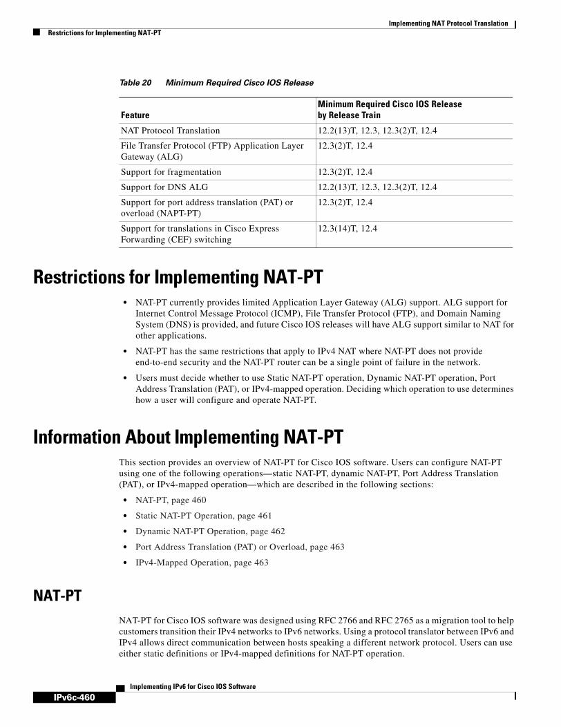
IPv6c-460
Implementing NAT Protocol TranslationRestrictions for Implementing NAT-PT
Implementing IPv6 for Cisco IOS Software
Restrictions for Implementing NAT-PT• NAT-PT currently provides limited Application Layer Gateway (ALG) support. ALG support for
Internet Control Message Protocol (ICMP), File Transfer Protocol (FTP), and Domain Naming System (DNS) is provided, and future Cisco IOS releases will have ALG support similar to NAT for other applications.
• NAT-PT has the same restrictions that apply to IPv4 NAT where NAT-PT does not provide end-to-end security and the NAT-PT router can be a single point of failure in the network.
• Users must decide whether to use Static NAT-PT operation, Dynamic NAT-PT operation, Port Address Translation (PAT), or IPv4-mapped operation. Deciding which operation to use determines how a user will configure and operate NAT-PT.
Information About Implementing NAT-PTThis section provides an overview of NAT-PT for Cisco IOS software. Users can configure NAT-PT using one of the following operations—static NAT-PT, dynamic NAT-PT, Port Address Translation (PAT), or IPv4-mapped operation—which are described in the following sections:
• NAT-PT, page 460
• Static NAT-PT Operation, page 461
• Dynamic NAT-PT Operation, page 462
• Port Address Translation (PAT) or Overload, page 463
• IPv4-Mapped Operation, page 463
NAT-PTNAT-PT for Cisco IOS software was designed using RFC 2766 and RFC 2765 as a migration tool to help customers transition their IPv4 networks to IPv6 networks. Using a protocol translator between IPv6 and IPv4 allows direct communication between hosts speaking a different network protocol. Users can use either static definitions or IPv4-mapped definitions for NAT-PT operation.
Table 20 Minimum Required Cisco IOS Release
FeatureMinimum Required Cisco IOS Release by Release Train
NAT Protocol Translation 12.2(13)T, 12.3, 12.3(2)T, 12.4
File Transfer Protocol (FTP) Application Layer Gateway (ALG)
12.3(2)T, 12.4
Support for fragmentation 12.3(2)T, 12.4
Support for DNS ALG 12.2(13)T, 12.3, 12.3(2)T, 12.4
Support for port address translation (PAT) or overload (NAPT-PT)
12.3(2)T, 12.4
Support for translations in Cisco Express Forwarding (CEF) switching
12.3(14)T, 12.4

IPv6c-461
Implementing NAT Protocol TranslationInformation About Implementing NAT-PT
Implementing IPv6 for Cisco IOS Software
Figure 33 shows NAT-PT runs on a router between an IPv6 network and an IPv4 network to connect an IPv6-only node with an IPv4-only node.
Figure 33 NAT-PT Basic Operation
Although IPv6 solves addressing issues for customers, a long transition period is likely before customers move to an exclusive IPv6 network environment. During the transition period any new IPv6-only networks will need to continue to communicate with existing IPv4 networks. NAT-PT is designed to be deployed to allow direct communication between IPv6-only networks and IPv4-only networks. For a service provider customer an example could be an IPv6-only client trying to access an IPv4-only web server. Enterprise customers will also migrate to IPv6 in stages, and many of their IPv4-only networks will be operational for several years. Dual stack networks may have some IPv6-only hosts configured to take advantage of the IPv6 autoconfiguration, global addressing, and simpler management, and these hosts can use NAT-PT to communicate with existing IPv4-only networks in the same organization.
One of the benefits of NAT-PT is that no changes are required to existing hosts because all the NAT-PT configurations are performed at the NAT-PT router. Customers with existing stable IPv4 networks can introduce an IPv6 network and use NAT-PT to allow communication without disrupting the existing network. To further illustrate the seamless transition, File Transfer Protocol (FTP) can be used between IPv4 and IPv6 networks just as within an IPv4 network. Packet fragmentation is enabled by default when IPv6 is configured allowing IPv6 and IPv4 networks to resolve fragmentation problems between the networks. Without the ability to resolve fragmentation, connectivity could become intermittent when fragmented packets might be dropped or improperly interpreted.
Cisco has developed other transition techniques including dual stack, IPv6 over MPLS, and tunneling. NAT-PT should not be used when other native communication techniques exist. If a host is configured as a dual stack host with both IPv4 and IPv6, we do not recommend using NAT-PT to communicate between the dual stack host and an IPv6-only or IPv4-only host. NAT-PT is not recommended for a scenario in which an IPv6-only network is trying to communicate to another IPv6-only network via an IPv4 backbone or vice versa, because NAT-PT would require a double translation to be performed. In this scenario, tunneling techniques would be recommended.
The following sections describe the operations that may be used to configure NAT-PT. Users have the option to use one of the following operations for NAT-PT operation, but not all four.
Static NAT-PT OperationStatic NAT-PT uses static translation rules to map one IPv6 address to one IPv4 address. IPv6 network nodes communicate with IPv4 network nodes using an IPv6 mapping of the IPv4 address configured on the NAT-PT router.
Figure 34 shows how the IPv6-only node named A can communicate with the IPv4-only node named C using NAT-PT. The NAT-PT device is configured to map the source IPv6 address for node A of 2001:0db8:bbbb:1::1 to the IPv4 address 192.168.99.2. NAT-PT is also configured to map the source address of IPv4 node C, 192.168.30.1 to 2001:0db8::a. When packets with a source IPv6 address of node
8287
4
IPv6network IPv4
IPv4-onlynodeIPv6-only
node
NAT-PT

IPv6c-462
Implementing NAT Protocol TranslationInformation About Implementing NAT-PT
Implementing IPv6 for Cisco IOS Software
A are received at the NAT-PT router they are translated to have a destination address to match node C in the IPv4-only network. NAT-PT can also be configured to match a source IPv4 address and translate the packet to an IPv6 destination address to allow an IPv4-only host communicate with an IPv6-only host.
If you have multiple IPv6-only or IPv4-only hosts that need to communicate, you may need to configure many static NAT-PT mappings. Static NAT-PT is useful when applications or servers require access to a stable IPv4 address. Accessing an external IPv4 DNS server is an example where static NAT PT can be used.
Figure 34 Static NAT-PT Operation
Dynamic NAT-PT OperationDynamic NAT-PT allows multiple NAT-PT mappings by allocating addresses from a pool. NAT-PT is configured with a pool of IPv6 and/or IPv4 addresses. At the start of a NAT-PT session a temporary address is dynamically allocated from the pool. The number of addresses available in the address pool determines the maximum number of concurrent sessions. The NAT-PT device records each mapping between addresses in a dynamic state table.
Figure 35 shows how dynamic NAT-PT operates. The IPv6-only node B can communicate with the IPv4-only node D using dynamic NAT-PT. The NAT-PT device is configured with an IPv6 access list, prefix list, or route map to determine which packets are to be translated by NAT-PT. A pool of IPv4 addresses—10.21.8.1 to 10.21.8.10 in Figure 35— is also configured. When an IPv6 packet to be translated is identified, NAT-PT uses the configured mapping rules and assigns a temporary IPv4 address from the configured pool of IPv4 addresses.
Figure 35 Dynamic NAT-PT Operation
Dynamic NAT-PT translation operation requires at least one static mapping for the IPv4 DNS server.
8287
5
IPv6network IPv4
IPv4-onlynode
IPv6-onlynode
NAT-PT
NAT-PT prefix: 2001:0DB8:yyyy::/96
192.168.30.1
Src Addr2001:0DB8:bbbb:1::1
Src Addr192.168.99.2
Dest Addr192.168.30.1
2001:0DB8:bbbb:1::1
Dest Addr2001:0DB8:yyyy::a
NAT-PTtranslation
A C
8287
6
IPv6network IPv4
IPv4-onlynode
IPv6-onlynode
B D
NAT-PT192.168.30.12001:0DB8:bbbb:1::1
NAT-PT IPv4 address pool: 10.21.8.1 – 10.21.8.10

IPv6c-463
Implementing NAT Protocol TranslationHow to Implement NAT-PT
Implementing IPv6 for Cisco IOS Software
After the IPv6 to IPv4 connection is established, the reply packets going from IPv4 to IPv6 take advantage of the previously established dynamic mapping to translate back from IPv4 to IPv6. If the connection is initiated by an IPv4-only host then the explanation is reversed.
Port Address Translation (PAT) or OverloadPort Address Translation (PAT), also known as Overload, allows a single IPv4 address to be used among multiple sessions by multiplexing on the port number to associate several IPv6 users with a single IPv4 address. The Port Address Translation can be accomplished through a specific interface or through a pool of addresses. Figure 36 shows multiple IPv6 addresses from the IPv6 network linked to a single IPv4 interface into the IPv4 network.
Figure 36 Port Address Translation
IPv4-Mapped OperationCustomers can also send traffic from their IPv6 network to an IPv4 network without configuring IPv6 destination address mapping. A packet arriving at an interface is checked to discover if it has a NAT-PT prefix that was configured with the ipv6 nat prefix v4-mapped command. If the prefix does match, then an access-list check is performed to discover if the source address matches the access list or prefix list. If the prefix does not match, the packet is dropped.
If the prefix matches, source address translation is performed. If a rule has been configured for the source address translation, the last 32 bits of the destination IPv6 address is used as the IPv4 destination and a flow entry is created.
How to Implement NAT-PT• Configuring Basic IPv6 to IPv4 Connectivity for NAT-PT, page 464 (required)
• Configuring IPv4-Mapped NAT-PT, page 465 (required)
• Configuring Mappings for IPv6 Hosts Accessing IPv4 Hosts, page 466 (required)
• Configuring Mappings for IPv4 Hosts Accessing IPv6 Hosts, page 469 (optional)
• Configuring Port Address Translation, page 470
9566
9
V61
IPv4 Network
IPv6 Network
NAT-PT Router
e0-190.1.1.101V62
V63

IPv6c-464
Implementing NAT Protocol TranslationHow to Implement NAT-PT
Implementing IPv6 for Cisco IOS Software
• Verifying NAT-PT Configuration and Operation, page 472 (optional)
Configuring Basic IPv6 to IPv4 Connectivity for NAT-PTThis task explains how to configure the NAT-PT prefix globally, and enable NAT-PT on an interface. For NAT-PT to be operational, NAT-PT must be enabled on both the incoming and outgoing interfaces.
NAT-PT Prefix
An IPv6 prefix with a prefix length of 96 must be specified for NAT-PT to use. The IPv6 prefix can be a unique local unicast prefix, a subnet of your allocated IPv6 prefix, or even an extra prefix obtained from your Internet service provider (ISP). The NAT-PT prefix is used to match a destination address of an IPv6 packet. If the match is successful, NAT-PT will use the configured address mapping rules to translate the IPv6 packet to an IPv4 packet. The NAT-PT prefix can be configured globally or with different IPv6 prefixes on individual interfaces. Using a different NAT-PT prefix on several interfaces allows the NAT-PT router to support an IPv6 network with multiple exit points to IPv4 networks.
SUMMARY STEPS
1. enable
2. configure terminal
3. ipv6 nat prefix ipv6-prefix/prefix-length
4. interface type number
5. ipv6 address ipv6-prefix {/prefix-length | link-local}
6. ipv6 nat
7. exit
8. interface type number
9. ip address ip-address mask [secondary]
10. ipv6 nat
DETAILED STEPS
Command or Action Purpose
Step 1 enable
Example:Router> enable
Enables privileged EXEC mode.
• Enter your password if prompted.
Step 2 configure terminal
Example:Router# configure terminal
Enters global configuration mode.

IPv6c-465
Implementing NAT Protocol TranslationHow to Implement NAT-PT
Implementing IPv6 for Cisco IOS Software
Configuring IPv4-Mapped NAT-PTThe following task describes how to enable customers to send traffic from their IPv6 network to an IPv4 network without configuring IPv6 destination address mapping. This task shows the the ipv6 nat prefix v4-mapped command configured on a specified interface, but the command could alternatively be configured globally:
Step 3 ipv6 nat prefix ipv6-prefix/prefix-length
Example:Router# ipv6 nat prefix 2001:0db8::/96
Assigns an IPv6 prefix as a global NAT-PT prefix.
• Matching destination prefixes in IPv6 packets are translated by NAT-PT.
• The only prefix length supported is 96.
Step 4 interface type number
Example:Router(config)# interface ethernet 3/1
Specifies an interface type and number, and places the router in interface configuration mode.
Step 5 ipv6 address ipv6-address {/prefix-length | link-local}
Example:Router(config-if)# ipv6 address 2001:0db8:yyyy:1::9/64
Specifies an IPv6 address assigned to the interface and enables IPv6 processing on the interface.
Step 6 ipv6 nat
Example:Router(config-if)# ipv6 nat
Enables NAT-PT on the interface.
Step 7 exit
Example:Router(config-if)# exit
Exits interface configuration mode, and returns the router to global configuration mode.
Step 8 interface type number
Example:Router(config)# interface ethernet 3/3
Specifies an interface type and number, and places the router in interface configuration mode.
Step 9 ip address ip-address mask [secondary]
Example:Router(config-if)# ip address 192.168.30.9 255.255.255.0
Specifies an IP address and mask assigned to the interface and enables IP processing on the interface.
Step 10 ipv6 nat
Example:Router(config-if)# ipv6 nat
Enables NAT-PT on the interface.
Command or Action Purpose

IPv6c-466
Implementing NAT Protocol TranslationHow to Implement NAT-PT
Implementing IPv6 for Cisco IOS Software
SUMMARY STEPS
1. enable
2. configure terminal
3. interface type number
4. ipv6 nat prefix ipv6-prefix v4-mapped {access-list-name | ipv6-prefix}
DETAILED STEPS
Configuring Mappings for IPv6 Hosts Accessing IPv4 HostsThis task explains how to configure static or dynamic IPv6 to IPv4 address mappings. The dynamic address mappings include assigning a pool of IPv4 addresses and using an access list, prefix list, or route map to define which packets are to be translated.
SUMMARY STEPS
1. enable
2. configure terminal
3. ipv6 nat v6v4 source ipv6-address ipv4-addressoripv6 nat v6v4 source {list access-list-name | route-map map-name} pool name
4. ipv6 nat v6v4 pool name start-ipv4 end-ipv4 prefix-length prefix-length
5. ipv6 nat translation [max-entries number] {timeout | udp-timeout | dns-timeout | tcp-timeout | finrst-timeout | icmp-timeout} {seconds | never}
Command or Action Purpose
Step 1 enable
Example:Router> enable
Enables privileged EXEC mode.
• Enter your password if prompted.
Step 2 configure terminal
Example:Router# configure terminal
Enters global configuration mode.
Step 3 interface type number
Example:Router(config)# interface ethernet 3/1
Specifies an interface type and number, and places the router in interface configuration mode.
Step 4 ipv6 nat prefix ipv6-prefix v4-mapped {access-list-name | ipv6-prefix}
Example:Router(config-if)# ipv6 nat prefix 2001::/96
v4-mapped v4map_acl
Enables customers to send traffic from their IPv6 network to an IPv4 network without configuring IPv6 destination address mapping.

IPv6c-467
Implementing NAT Protocol TranslationHow to Implement NAT-PT
Implementing IPv6 for Cisco IOS Software
6. ipv6 access-list access-list-name
7. permit {protocol} {source-ipv6-prefix/prefix-length | any | host source-ipv6-address} [operator [port-number]] {destination-ipv6-prefix/prefix-length | any | host destination-ipv6-address}
8. exit
9. show ipv6 nat translations [icmp | tcp | udp] [verbose]
10. show ipv6 nat statistics
DETAILED STEPS
Command or Action Purpose
Step 1 enable
Example:Router> enable
Enables privileged EXEC mode.
• Enter your password if prompted.
Step 2 configure terminal
Example:Router# configure terminal
Enters global configuration mode.
Step 3 ipv6 nat v6v4 source ipv6-address ipv4-addressoripv6 nat v6v4 source {list access-list-name | route-map map-name} pool name
Example:Router(config)# ipv6 nat v6v4 source 2001:0db8:yyyy:1::1 10.21.8.10
Example:Router(config)# ipv6 nat v6v4 source list pt-list1 pool v4pool
Enables a static IPv6 to IPv4 address mapping using NAT-PT.
or
Enables a dynamic IPv6 to IPv4 address mapping using NAT-PT.
• Use the list or route-map keyword to specify a prefix list, access list, or a route map to define which packets are translated.
• Use the pool keyword to specify the name of a pool of addresses, created by the ipv6 nat v6v4 pool command, to be used in dynamic NAT-PT address mapping.
Step 4 ipv6 nat v6v4 pool name start-ipv4 end-ipv4 prefix-length prefix-length
Example:Router(config)# ipv6 nat v6v4 pool v4pool 10.21.8.1 10.21.8.10 prefix-length 24
Specifies a pool of IPv4 addresses to be used by NAT-PT for dynamic address mapping.
Step 5 ipv6 nat translation [max-entries number] {timeout | udp-timeout | dns-timeout | tcp-timeout | finrst-timeout | icmp-timeout} {seconds | never}
Example:Router(config)# ipv6 nat translation udp-timeout 600
(Optional) Specifies the time after which NAT-PT translations time out.

IPv6c-468
Implementing NAT Protocol TranslationHow to Implement NAT-PT
Implementing IPv6 for Cisco IOS Software
Step 6 ipv6 access-list access-list-name
Example:Router(config)# ipv6 access-list pt-list1
(Optional) Defines an IPv6 access list and enters IPv6 access list configuration mode. The router prompt changes to Router(config-ipv6-acl)#.
• The access-list name argument specifies the name of the IPv6 access control list (ACL). IPv6 ACL names cannot contain a space or quotation mark, or begin with a numeral.
Step 7 permit {protocol} {source-ipv6-prefix/prefix-length | any | host source-ipv6-address} [operator [port-number]] {destination-ipv6-prefix/prefix-length | any | host destination-ipv6-address}
Example:Router(config-ipv6-acl)# permit ipv6 2001:0db8:bbbb:1::/64 any
(Optional) Specifies permit conditions for an IPv6 ACL.
• The protocol argument specifies the name or number of an Internet protocol. It can be one of the keywords ahp, esp, icmp, ipv6, pcp, sctp, tcp, or udp, or an integer in the range from 0 to 255 representing an IPv6 protocol number.
• The source-ipv6-prefix/prefix-length and destination-ipv6-prefix/prefix-length arguments specify the source and destination IPv6 network or class of networks about which to set permit conditions. These arguments must be in the form documented in RFC 2373 where the address is specified in hexadecimal using 16-bit values between colons.
• The any keyword is an abbreviation for the IPv6 prefix ::/0.
• The host source-ipv6-address keyword and argument combination specifies the source IPv6 host address about which to set permit conditions. The source-ipv6-address argument must be in the form documented in RFC 2373 where the address is specified in hexadecimal using 16-bit values between colons.
• Only the arguments and keywords relevant to this task are specified here. Refer to the permit command in the IPv6 for Cisco IOS Command Reference document for information on supported arguments and keywords.
Step 8 exit
Example:Router(config-if)# exit
Exits access list configuration mode, and returns the router to global configuration mode. Enter the exit command twice to return to privileged EXEC mode.
Command or Action Purpose

IPv6c-469
Implementing NAT Protocol TranslationHow to Implement NAT-PT
Implementing IPv6 for Cisco IOS Software
What to Do Next
If you do not require any IPv4 to IPv6 mappings, proceed to the “Verifying NAT-PT Configuration and Operation” task.
Configuring Mappings for IPv4 Hosts Accessing IPv6 HostsThis optional task explains how to configure static or dynamic IPv4 to IPv6 address mappings. The dynamic address mappings include assigning a pool of IPv6 addresses and using an access list, prefix list, or route map to define which packets are to be translated.
SUMMARY STEPS
1. enable
2. configure terminal
3. ipv6 nat v4v6 source ipv4-address ipv6-addressoripv6 nat v4v6 source list {access-list-number | name} pool name
4. ipv6 nat v4v6 pool name start-ipv6 end-ipv6 prefix-length prefix-length
5. access-list {access-list-name | number} {deny | permit} [source source-wildcard] [log]
DETAILED STEPS
Step 1 show ipv6 nat translations [icmp | tcp | udp] [verbose]
Example:Router> show ipv6 nat translations verbose
(Optional) Displays active NAT-PT translations.
• Use the optional icmp, tcp, and udp keywords to display detailed information about the NAT-PT translation events for the specified protocol.
• Use the optional verbose keyword to display more detailed information about the active translations.
Step 1 show ipv6 nat statistics
Example:Router> show ipv6 nat statistics
(Optional) Displays NAT-PT statistics.
Command or Action Purpose
Command or Action Purpose
Step 1 enable
Example:Router> enable
Enables privileged EXEC mode.
• Enter your password if prompted.
Step 2 configure terminal
Example:Router# configure terminal
Enters global configuration mode.
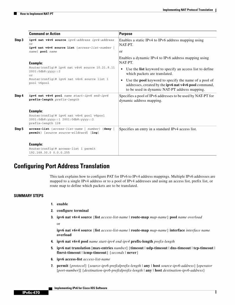
IPv6c-470
Implementing NAT Protocol TranslationHow to Implement NAT-PT
Implementing IPv6 for Cisco IOS Software
Configuring Port Address TranslationThis task explains how to configure PAT for IPv6 to IPv4 address mappings. Multiple IPv6 addresses are mapped to a single IPv4 address or to a pool of IPv4 addresses and using an access list, prefix list, or route map to define which packets are to be translated.
SUMMARY STEPS
1. enable
2. configure terminal
3. ipv6 nat v6v4 source {list access-list-name | route-map map-name} pool name overload
or
ipv6 nat v6v4 source {list access-list-name | route-map map-name} interface interface name overload
4. ipv6 nat v6v4 pool name start-ipv4 end-ipv4 prefix-length prefix-length
5. ipv6 nat translation [max-entries number] {timeout | udp-timeout | dns-timeout | tcp-timeout | finrst-timeout | icmp-timeout} {seconds | never}
6. ipv6 access-list access-list-name
7. permit {protocol} {source-ipv6-prefix/prefix-length | any | host source-ipv6-address} [operator [port-number]] {destination-ipv6-prefix/prefix-length | any | host destination-ipv6-address}
Step 3 ipv6 nat v4v6 source ipv6-address ipv4-addressoripv6 nat v4v6 source list {access-list-number | name} pool name
Example:Router(config)# ipv6 nat v4v6 source 10.21.8.11 2001:0db8:yyyy::2orRouter(config)# ipv6 nat v4v6 source list 1 pool v6pool
Enables a static IPv4 to IPv6 address mapping using NAT-PT.
or
Enables a dynamic IPv4 to IPv6 address mapping using NAT-PT.
• Use the list keyword to specify an access list to define which packets are translated.
• Use the pool keyword to specify the name of a pool of addresses, created by the ipv6 nat v4v6 pool command, to be used in dynamic NAT-PT address mapping.
Step 4 ipv6 nat v4v6 pool name start-ipv6 end-ipv6 prefix-length prefix-length
Example:Router(config)# ipv6 nat v4v6 pool v6pool 2001:0db8:yyyy::1 2001:0db8:yyyy::2 prefix-length 128
Specifies a pool of IPv6 addresses to be used by NAT-PT for dynamic address mapping.
Step 5 access-list {access-list-name | number} {deny | permit} [source source-wildcard] [log]
Example:Router(config)# access-list 1 permit 192.168.30.0 0.0.0.255
Specifies an entry in a standard IPv4 access list.
Command or Action Purpose

IPv6c-471
Implementing NAT Protocol TranslationHow to Implement NAT-PT
Implementing IPv6 for Cisco IOS Software
DETAILED STEPS
Command or Action Purpose
Step 1 enable
Example:Router> enable
Enables privileged EXEC mode.
• Enter your password if prompted.
Step 2 configure terminal
Example:Router# configure terminal
Enters global configuration mode.
Step 3 ipv6 nat v6v4 source {list access-list-name | route-map map-name} pool name overloadoripv6 nat v6v4 source {list access-list-name | route-map map-name} interface interface name overload
Example:Router(config)# ipv6 nat v6v4 source 2001:0db8:yyyy:1::1 10.21.8.10
Example:Router(config)# ipv6 nat v6v4 source list pt-list1 pool v4pool overload
Enables a dynamic IPv6 to IPv4 address overload mapping using a pool address.
or
Enables a dynamic IPv6 to IPv4 address overload mapping using an interface address.
• Use the list or route-map keyword to specify a prefix list, access list, or a route map to define which packets are translated.
• Use the pool keyword to specify the name of a pool of addresses, created by the ipv6 nat v6v4 pool command, to be used in dynamic NAT-PT address mapping.
• Use the interface keyword to specify the interface address to be used for overload.
Step 4 ipv6 nat v6v4 pool name start-ipv4 end-ipv4 prefix-length prefix-length
Example:Router(config)# ipv6 nat v6v4 pool v4pool 10.21.8.1 10.21.8.10 prefix-length 24
Specifies a pool of IPv4 addresses to be used by NAT-PT for dynamic address mapping.
Step 5 ipv6 nat translation [max-entries number] {timeout | udp-timeout | dns-timeout | tcp-timeout | finrst-timeout | icmp-timeout} {seconds | never}
Example:Router(config)# ipv6 nat translation udp-timeout 600
(Optional) Specifies the time after which NAT-PT translations time out.

IPv6c-472
Implementing NAT Protocol TranslationHow to Implement NAT-PT
Implementing IPv6 for Cisco IOS Software
What to Do Next
If you do not require any Ipv6-to-IPv4 or IPv4-to-IPv6 mappings, proceed to the “Verifying NAT-PT Configuration and Operation” task.
Verifying NAT-PT Configuration and OperationThis task explains how to display information to verify the configuration and operation of NAT-PT.
SUMMARY STEPS
1. clear ipv6 nat translation *
Step 6 ipv6 access-list access-list-name
Example:Router(config)# ipv6 access-list pt-list1
(Optional) Defines an IPv6 access list and enters IPv6 access list configuration mode. The router prompt changes to Router(config-ipv6-acl)#.
• The access-list name argument specifies the name of the IPv6 access control list (ACL). IPv6 ACL names cannot contain a space or quotation mark, or begin with a numeral.
Step 7 permit {protocol} {source-ipv6-prefix/prefix-length | any | host source-ipv6-address} [operator [port-number]] {destination-ipv6-prefix/prefix-length | any | host destination-ipv6-address}
Example:Router(config-ipv6-acl)# permit ipv6 2001:0db8:bbbb:1::/64 any
(Optional) Specifies permit conditions for an IPv6 ACL.
• The protocol argument specifies the name or number of an Internet protocol. It can be one of the keywords ahp, esp, icmp, ipv6, pcp, sctp, tcp, or udp, or an integer in the range from 0 to 255 representing an IPv6 protocol number.
• The source-ipv6-prefix/prefix-length and destination-ipv6-prefix/prefix-length arguments specify the source and destination IPv6 network or class of networks about which to set permit conditions. These arguments must be in the form documented in RFC 2373 where the address is specified in hexadecimal using 16-bit values between colons.
• The any keyword is an abbreviation for the IPv6 prefix ::/0.
• The host source-ipv6-address keyword and argument combination specifies the source IPv6 host address about which to set permit conditions. The source-ipv6-address argument must be in the form documented in RFC 2373 where the address is specified in hexadecimal using 16-bit values between colons.
• Only the arguments and keywords relevant to this task are specified here. Refer to the permit command in the IPv6 for Cisco IOS Command Reference document for information on supported arguments and keywords.
Command or Action Purpose

IPv6c-473
Implementing NAT Protocol TranslationHow to Implement NAT-PT
Implementing IPv6 for Cisco IOS Software
2. enable
3. debug ipv6 nat [detailed]
4. debug ipv6 nat [port]
DETAILED STEPS
Output Examples
This section provides the following output examples:
• Sample Output for the show ipv6 nat translations Command
• Sample Output for the show ipv6 nat statistics Command
• Sample Output for the clear ipv6 nat translation Command
• Sample Output for the debug ipv6 nat Command
Command or Action Purpose
Step 1 clear ipv6 nat translation *
Example:Router> clear ipv6 nat translation *
(Optional) Clears dynamic NAT-PT translations from the dynamic translation state table.
• Use the * keyword to clear all dynamic NAT-PT translations.
Note Static translation configuration is not affected by this command.
Step 2 enable
Example:Router> enable
Enables higher privilege levels, such as privileged EXEC mode.
• Enter your password if prompted.
Step 3 debug ipv6 nat [detailed]
Example:Router# debug ipv6 nat detail
(Optional) Displays debugging messages for NAT-PT translation events.
• Use the detailed keyword to display more detailed information about the NAT-PT translation events.
Step 4 debug ipv6 nat [port]
Example:Router# debug ipv6 nat port
Displays port allocation events during NAT-PT overload operation.

IPv6c-474
Implementing NAT Protocol TranslationHow to Implement NAT-PT
Implementing IPv6 for Cisco IOS Software
Sample Output for the show ipv6 nat translations Command
In the following example, output information about active NAT-PT translations is displayed using the show ipv6 nat translations command:
Router> show ipv6 nat translations
Prot IPv4 source IPv6 source IPv4 destination IPv6 destination --- --- --- 192.168.123.2 2001:0db8::2
--- --- --- 192.168.122.10 2001:0db8::10
tcp 192.168.124.8,11047 2001:0db8:3::8,11047 192.168.123.2,23 2001:0db8::2,23
udp 192.168.124.8,52922 2001:0db8:3::8,52922 192.168.123.2,69 2001::2,69
udp 192.168.124.8,52922 2001:0db8:3::8,52922 192.168.123.2,52922 2001:0db8::2,52922
--- 192.168.124.8 2001:0db8:3::8 192.168.123.2 2001:0db8::2
--- 192.168.124.8 2001:0db8:3::8 --- ---
--- 192.168.121.4 2001:0db8:5::4 --- ---

IPv6c-475
Implementing NAT Protocol TranslationHow to Implement NAT-PT
Implementing IPv6 for Cisco IOS Software
In the following example, detailed output information about active NAT-PT translations is displayed using the show ipv6 nat translations command with the verbose keyword:
Router> show ipv6 nat translations verbose
Prot IPv4 source IPv6 source IPv4 destination IPv6 destination --- --- --- 192.168.123.2 2001:0db8::2 create 00:04:24, use 00:03:24,
--- --- --- 192.168.122.10 2001:0db8::10 create 00:04:24, use 00:04:24,
tcp 192.168.124.8,11047 2001:0db8:3::8,11047 192.168.123.2,23 2001:0db8::2,23 create 00:03:24, use 00:03:20, left 00:16:39,
udp 192.168.124.8,52922 2001:0db8:3::8,52922 192.168.123.2,69 2001:0db8::2,69 create 00:02:51, use 00:02:37, left 00:17:22,
udp 192.168.124.8,52922 2001:0db8:3::8,52922 192.168.123.2,52922 2001:0db8::2,52922 create 00:02:48, use 00:02:30, left 00:17:29,
--- 192.168.124.8 2001:0db8:3::8 192.168.123.2 2001:0db8::2 create 00:03:24, use 00:02:34, left 00:17:25,
--- 192.168.124.8 2001:0db8:3::8 --- --- create 00:04:24, use 00:03:24,
--- 192.168.121.4 2001:0db8:5::4 --- --- create 00:04:25, use 00:04:25,
Sample Output for the show ipv6 nat statistics Command
In the following example, output information about NAT-PT statistics is displayed using the show ipv6 nat statistics command:
Router> show ipv6 nat statistics
Total active translations: 4 (4 static, 0 dynamic; 0 extended) NAT-PT interfaces: Ethernet3/1, Ethernet3/3 Hits: 0 Misses: 0 Expired translations: 0

IPv6c-476
Implementing NAT Protocol TranslationConfiguration Examples for NAT-PT
Implementing IPv6 for Cisco IOS Software
Sample Output for the clear ipv6 nat translation Command
In the following example, all dynamic NAT-PT translations are cleared from the dynamic translation state table using the clear ipv6 nat translation command with the * keyword. When the output information about active NAT-PT translations is then displayed using the show ipv6 nat translations command, only the static translation configurations remain. Compare this show command output with the output for the show ipv6 nat translations command in Step 1.
Router> clear ipv6 nat translation *
Router> show ipv6 nat translations
Prot IPv4 source IPv6 source IPv4 destination IPv6 destination --- --- --- 192.168.123.2 2001:0db8::2
--- --- --- 192.168.122.10 2001:0db8::10
--- 192.168.124.8 2001:0db8:3::8 --- ---
--- 192.168.121.4 2001:0db8:5::4 --- ---
Sample Output for the debug ipv6 nat Command
In the following example, debugging messages for NAT-PT translation events are displayed using the debug ipv6 nat command:
Router# debug ipv6 nat
00:06:06: IPv6 NAT: icmp src (2001:0db8:3002::8) -> (192.168.124.8), dst (2001:0db8:2001::2) -> (192.168.123.2)00:06:06: IPv6 NAT: icmp src (192.168.123.2) -> (2001:0db8:2001::2), dst (192.168.124.8) -> (2001:0db8:3002::8)00:06:06: IPv6 NAT: icmp src (2001:0db8:3002::8) -> (192.168.124.8), dst (2001:0db8:2001::2) -> (192.168.123.2) 00:06:06: IPv6 NAT: icmp src (192.168.123.2) -> (2001:0db8:2001::2), dst (192.168.124.8) -> (2001:0db8:3002::8) 00:06:06: IPv6 NAT: tcp src (2001:0db8:3002::8) -> (192.168.124.8), dst (2001:0db8:2001::2) -> (192.168.123.2) 00:06:06: IPv6 NAT: tcp src (192.168.123.2) -> (2001:0db8:2001::2), dst (192.168.124.8) -> (2001:0db8:3002::8) 00:06:06: IPv6 NAT: tcp src (2001:0db8:3002::8) -> (192.168.124.8), dst (2001:0db8:2001::2) -> (192.168.123.2) 00:06:06: IPv6 NAT: tcp src (2001:0db8:3002::8) -> (192.168.124.8), dst (2001:0db8:2001::2) -> (192.168.123.2) 00:06:06: IPv6 NAT: tcp src (2001:0db8:3002::8) -> (192.168.124.8), dst (2001:0db8:2001::2) -> (192.168.123.2) 00:06:06: IPv6 NAT: tcp src (192.168.123.2) -> (2001:0db8:2001::2), dst (192.168.124.8) -> (2001:0db8:3002::8)
Configuration Examples for NAT-PTThis section provides the following configuration examples:
• Static NAT-PT Configuration: Example, page 477

IPv6c-477
Implementing NAT Protocol TranslationConfiguration Examples for NAT-PT
Implementing IPv6 for Cisco IOS Software
• Enabling Traffic to be Sent from an IPv6 Network to an IPv4 Network without Using IPv6 Dastination Address Mapping: Example, page 477
• Dynamic NAT-PT Configuration for IPv6 Hosts Accessing IPv4 Hosts: Example, page 477
• Dynamic NAT-PT Configuration for IPv4 Hosts Accessing IPv6 Hosts Example, page 478
Static NAT-PT Configuration: ExampleThe following example configures the NAT-PT prefix globally, enables NAT-PT on two interfaces, and configures two static NAT-PT mappings. Ethernet interface 3/1 is configured as IPv6 only, and Ethernet interface 3/3 is configured as IPv4 only.
interface Ethernet3/1 ipv6 address 2001:0db8:3002::9/64 ipv6 enable ipv6 nat ! interface Ethernet3/3 ip address 192.168.30.9 255.255.255.0 ipv6 nat ! ipv6 nat v4v6 source 192.168.30.1 2001:0db8:0::2 ipv6 nat v6v4 source 2001:0db8:bbbb:1::1 10.21.8.10 ipv6 nat prefix 2001:0db8:0::/96
Enabling Traffic to be Sent from an IPv6 Network to an IPv4 Network without Using IPv6 Dastination Address Mapping: Example
In the following example, the access list permits any IPv6 source address with the prefix 2001::/96 to go to the destination with a 2000::/96 prefix. The destination is then translated to the last 32 bit of its IPv6 address; for example: source address = 2001::1, destination address = 2000::192.168.1.1. The destination then becomes 192.168.1.1 in the IPv4 network:
ipv6 nat prefix 2000::/96 v4-mapped v4map_acl
ipv6 access-list v4map_aclpermit ipv6 2001::/96 2000::/96
Dynamic NAT-PT Configuration for IPv6 Hosts Accessing IPv4 Hosts: ExampleThe following example configures the NAT-PT prefix globally, enables NAT-PT on two interfaces, and configures one static NAT-PT mapping (used, for example, to access a DNS server). A dynamic NAT-PT mapping is also configured to map IPv6 addresses to IPv4 addresses using a pool of IPv4 addresses named v4pool. The packets to be translated by NAT-PT are filtered using an IPv6 access list named pt-list1. The User Datagram Protocol (UDP) translation entries are configured to time out after 10 minutes. Ethernet interface 3/1 is configured as IPv6 only, and Ethernet interface 3/3 is configured as IPv4 only.
interface Ethernet3/1 ipv6 address 2001:0db8:bbbb:1::9/64 ipv6 enable ipv6 nat ! interface Ethernet3/3

IPv6c-478
Implementing NAT Protocol TranslationWhere to Go Next
Implementing IPv6 for Cisco IOS Software
ip address 192.168.30.9 255.255.255.0 ipv6 nat ! ipv6 nat v4v6 source 192.168.30.1 2001:0db8:0::2 ipv6 nat v6v4 source list pt-list1 pool v4pool ipv6 nat v6v4 pool v4pool 10.21.8.1 10.21.8.10 prefix-length 24 ipv6 nat translation udp-timeout 600ipv6 nat prefix 2001:0db8:1::/96 ! ipv6 access-list pt-list1 permit ipv6 2001:0db8:bbbb:1::/64 any
Dynamic NAT-PT Configuration for IPv4 Hosts Accessing IPv6 Hosts ExampleThe following example configures the NAT-PT prefix globally, enables NAT-PT on two interfaces, and configures one static NAT-PT mapping (used, for example, to access a DNS server). A dynamic NAT-PT mapping is also configured to map IPv4 addresses to IPv6 addresses using a pool of IPv6 addresses named v6pool. The packets to be translated by NAT-PT are filtered using an access list named pt-list2. Ethernet interface 3/1 is configured as IPv6 only, and Ethernet interface 3/3 is configured as IPv4 only.
interface Ethernet3/1 ipv6 address 2001:0db8:bbbb:1::9/64 ipv6 enable ipv6 nat ! interface Ethernet3/3 ip address 192.168.30.9 255.255.255.0 ipv6 nat ! ipv6 nat v4v6 source list pt-list2 pool v6pool ipv6 nat v4v6 pool v6pool 2001:0db8:0::1 2001:0db8:0::2 prefix-length 128 ipv6 nat v6v4 source 2001:0db8:bbbb:1::1 10.21.8.0 ipv6 nat prefix 2001:0db8:0::/96 ! access-list pt-list2 permit 192.168.30.0 0.0.0.255
Where to Go NextIf you want to implement IPv6 routing protocols, refer to the Implementing RIP for IPv6, Implementing IS-IS for IPv6, or the Implementing Multiprotocol BGP for IPv6 module.
Additional ReferencesFor additional information related to the NAT Protocol Translation feature, see the following references:
• Related Documents, page 479
• Standards, page 479
• MIBs, page 479
• RFCs, page 479
• Technical Assistance, page 480

IPv6c-479
Implementing NAT Protocol TranslationAdditional References
Implementing IPv6 for Cisco IOS Software
Related Documents
Standards
MIBs
RFCs
Related Topic Document Title
IP addressing and IP services configuration tasks “Configuring IP Addressing” and “Configuring IP Services” chapters in the Cisco IOS IP Configuration Guide, Release 12.4
IP addressing and IP services commands: complete command syntax, command mode, defaults, usage guidelines, and examples
Cisco IOS IP Command Reference, Volume 1 of 3: Addressing and Services, Release 12.4
IPv6 supported feature list Start Here: Cisco IOS Software Release Specifics for IPv6 Features
IPv6 commands: complete command syntax, command mode, defaults, usage guidelines, and examples
IPv6 for Cisco IOS Command Reference
IPv4 configuration and command reference information
Cisco IOS Release 12.4 Configuration Guides and Command References
Standards Title
No new or modified standards are supported by this feature, and support for existing standards has not been modified by this feature.
—
MIBs MIBs Link
No new or modified MIBs are supported by this feature, and support for existing MIBs has not been modified by this feature.
To locate and download MIBs for selected platforms, Cisco IOS releases, and feature sets, use Cisco MIB Locator found at the following URL:
http://www.cisco.com/go/mibs
RFCs Title
RFC 2765 Stateless IP/ICMP Translation Algorithm (SIIT)
RFC 2766 Network Address Translation - Protocol Translation (NAT-PT)

IPv6c-480
Implementing NAT Protocol TranslationAdditional References
Implementing IPv6 for Cisco IOS Software
Technical Assistance
Description Link
The Cisco Technical Support website contains thousands of pages of searchable technical content, including links to products, technologies, solutions, technical tips, and tools. Registered Cisco.com users can log in from this page to access even more content.
http://www.cisco.com/techsupport

IPv6c-481Implementing IPv6 for Cisco IOS Software
Implementing Policy-Based Routing for IPv6
Policy-based routing (PBR) for both IPv6 and IPv4 in Cisco IOS software allows a user to manually configure how received packets should be routed. PBR allows the user to identify packets using several attributes and to specify the next hop or output interface to which the packet should be sent. PBR also provides a basic packet-marking capability.
Finding Support Information for Platforms and Cisco IOS Software Images
Use Cisco Feature Navigator to find information about platform support and Cisco IOS software image support. Access Cisco Feature Navigator at http://www.cisco.com/go/fn. You must have an account on Cisco.com. If you do not have an account or have forgotten your username or password, click Cancel at the login dialog box and follow the instructions that appear.
Contents• Prerequisites for Policy-Based Routing for IPv6, page 481
• Restrictions for Policy-Based Routing for IPv6, page 482
• Information About Policy-Based Routing, page 482
• How to Implement Policy-Based Routing for IPv6, page 484
• Configuration Examples for Policy-Based Routing for IPv6, page 489
• Additional References, page 490
Prerequisites for Policy-Based Routing for IPv6• This module assumes that you are familiar with IPv6 addressing and basic configuration. Refer to
the Implementing Basic Connectivity for IPv6 module for more information.
• This module assumes that you are familiar with IPv4. Refer to the publications referenced in the “Related Documents” section for IPv4 configuration and command reference information, as needed.

IPv6c-482
Implementing Policy-Based Routing for IPv6Restrictions for Policy-Based Routing for IPv6
Implementing IPv6 for Cisco IOS Software
Restrictions for Policy-Based Routing for IPv6Distributed Cisco Express Forwarding (formerly known as dCEF) is supported on the Cisco 7500 series routers only.
Table 21 identifies the earliest release for each early-deployment release in which the feature became available.
Information About Policy-Based RoutingTo configure PBR for IPv6 for Cisco IOS software, you must understand the following concepts:
• Policy-Based Routing Overview, page 482
• How Policy-Based Routing Works, page 483
• When to Use Policy-Based Routing, page 484
Policy-Based Routing OverviewPBR gives you a flexible means of routing packets by allowing you to configure a defined policy for traffic flows, which leseens reliance on routes derived from routing protocols. To this end, PBR gives you more control over routing by extending and complementing the existing mechanisms provided by routing protocols. PBR allows you to set the IPv6 precedence. It also allows you to specify a path for certain traffic, such as priority traffic over a high-cost link.
PBR for IPv6 may be applied to both forwarded and originated IPv6 packets. For forwarded packets, PBR for IPv6 will be implemented as an IPv6 input interface feature, supported in the process, Cisco Express Forwarding (formerly known as CEF), and distributed Cisco Express Forwarding forwarding paths.
You can set up PBR as a way to route packets based on configured policies. For example, you can implement routing policies to allow or deny paths based on the identity of a particular end system, an application protocol, or the size of packets.
PBR allows you to perform the following tasks:
• Classify traffic based on extended access list criteria. Access lists, then, establish the match criteria.
• Set IPv6 precedence bits, giving the network the ability to enable differentiated classes of service.
• Route packets to specific traffic-engineered paths; you might need to route them to allow a specific quality of service (QoS) through the network.
Policies can be based on IPv6 address, port numbers, protocols, or size of packets. For a simple policy, you can use any one of these descriptors; for a complex policy, you can use all of them.
PBR allows you to classify and mark packets at the edge of the network. PBR marks a packet by setting its precedence value. The precedence value can be used directly by routers in the network core to apply the appropriate QoS to a packet, which keeps packet classification at your network edge.
Table 21 Minimum Required Cisco IOS Release
Feature Minimum Required Cisco IOS Release by Release
Policy-Based Routing for IPv6 12.3(7)T, 12.4, 12.4(2)T, 12.2(30)S

IPv6c-483
Implementing Policy-Based Routing for IPv6Information About Policy-Based Routing
Implementing IPv6 for Cisco IOS Software
How Policy-Based Routing WorksAll packets received on an interface with PBR enabled are passed through enhanced packet filters known as route maps. The route maps used by PBR dictate the policy, determining where to forward packets.
Route maps are composed of statements. The route map statements can be marked as permit or deny, and they are interpreted in the following ways:
• If a packet matches all match statements for a route map that is marked as permit, then the router attempts to policy route the packet using the set statements. Otherwise, the packet is forwarded normally.
• If the packet matches any match statements for a route map that is marked as deny, then the packet is not subject to PBR and is forwarded normally.
• If the statement is marked as permit and the packets do not match any route map statements, the packets are sent back through the normal forwarding channels and destination-based routing is performed.
You specify PBR on the interface that receives the packet, not on the interface from which the packet is sent.
Packet Matching
PBR for IPv6 will match packets using the match ipv6 address command in the associated PBR route map. Packet match criteria are those criteria supported by IPv6 access lists, as follows:
• Input interface
• Source IPv6 address (using a prefix list or a standard or extended access list [ACL])
• Destination IPv6 address (standard or extended ACL)
• Protocol (extended ACL)
• Source port and destination port (extended ACL)
• Differentiated services code point (DSCP) (extended ACL)
• Flow-label (extended ACL)
• Fragment (extended ACL)
Packets may also be matched by length using the match length statement in the PBR route map.
Match statements are evaluated first by the criteria specified in the match ipv6 address command and then by criteria specified in the match length command. Therefore, if both an ACL and a length statement are used, a packet will first be subject to an ACL match. Only packets that pass the ACL match will then be subject to the length match. Finally, only packets that pass both the ACL and the length statement will be policy routed.
Packet Forwarding Using Set Statements
PBR for IPv6 packet forwarding is controlled using a number of set statements in the PBR route map. These set statements are evaluated individually in the order shown, and PBR will attempt to forward the packet using each of the of the set statements in turn. PBR evaluates each set statement by itself, without reference to any prior or subsequent set statement.
You may set multiple forwarding statements in the PBR for IPv6 route map. The following set statements may be specified:
IPv6c-484
Implementing Policy-Based Routing for IPv6How to Implement Policy-Based Routing for IPv6
Implementing IPv6 for Cisco IOS Software
• IPv6 next hop. The next hop to which the packet should be sent. The next hop must be present in the Routing Information Base (RIB), it must be directly connected, and it must be a global IPv6 address. If the next hop is invalid, the set statement is ignored.
• Output interface. A packet is forwarded out of a specified interface. An entry for the packet destination address must exist in the IPv6 RIB, and the specified output interface must be in the path set. If the interface is invalid, the statement is ignored.
• Default IPv6 next hop. The next hop to which the packet should be sent. It must be a global IPv6 address. This set statement is used only when there is no explicit entry for the packet destination in the IPv6 RIB.
• Default output interface. The packet is forwarded out a specified interface. This set statement is used only when there is no explicit entry for the packet destination in the IPv6 RIB.
Note The order in which PBR evaluates the set statements is the order in which they are listed above. This order may differ from the order in which route-map set statements are listed by Cisco IOS show commands.
When to Use Policy-Based RoutingYou might use PBR if you want certain packets to be routed some way other than the obvious shortest path. For example, PBR can be used to provide the following functionality:
• Equal access
• Protocol-sensitive routing
• Source-sensitive routing
• Routing based on interactive versus batch traffic
• Routing based on dedicated links
Some applications or traffic can benefit from QoS-specific routing; for example, you could transfer stock records to a corporate office on a higher-bandwidth, higher-cost link for a short time while sending routine application data such as e-mail over a lower-bandwidth, lower-cost link.
How to Implement Policy-Based Routing for IPv6The tasks in the following sections explain how to implement Policy-Based Routing for IPv6:
• Enabling PBR on an Interface, page 484
• Enabling Local PBR for IPv6, page 487
• Enabling Cisco Express Forwarding-Switched PBR for IPv6, page 487
• Troubleshooting PBR for IPv6, page 488
Enabling PBR on an InterfaceTo enable PBR for IPv6, you must create a route map that specifies the packet match criteria and desired policy-route action. Then you associate the route map on the required interface. All packets arriving on the specified interface that match the match clauses will be subject to PBR.

IPv6c-485
Implementing Policy-Based Routing for IPv6How to Implement Policy-Based Routing for IPv6
Implementing IPv6 for Cisco IOS Software
This task enables PBR on an interface.
SUMMARY STEPS
1. enable
2. configure terminal
3. route-map map-tag [permit | deny] [sequence-number]
4. match length minimum-length maximum-length
or
match ipv6 address {prefix-list prefix-list-name | access-list-name}
5. set ipv6 precedence precedence-value
or
set ipv6 next-hop global-ipv6-address [global-ipv6-address...]
or
set interface type number [...type number]
or
set ipv6 default next-hop global-ipv6-address [global-ipv6-address...]
or
set default interface type number [...type number]
6. exit
7. interface type number
8. ipv6 policy route-map route-map-name
DETAILED STEPS
Command or Action Purpose
Step 1 enable
Example:Router> enable
Enables privileged EXEC mode.
• Enter your password if prompted.
Step 2 configure terminal
Example:Router# configure terminal
Enters global configuration mode.
Step 3 route-map map-tag [permit | deny] [sequence-number]
Example:Router(config)# route-map rip-to-ospf permit
Defines the conditions for redistributing routes from one routing protocol into another, or enables policy routing.
• Use the route-map command to enter route-map configuration mode.

IPv6c-486
Implementing Policy-Based Routing for IPv6How to Implement Policy-Based Routing for IPv6
Implementing IPv6 for Cisco IOS Software
Step 4 match length minimum-length maximum-length
or
match ipv6 address {prefix-list prefix-list-name | access-list-name}
Example:Router(config-route-map)# match length 3 200
or
Router(config-route-map)# match ipv6 address marketing
Specifies the match criteria.
• You can specify any or all of the following:
– Matches the Level 3 length of the packet.
– Matches a specified IPv6 access list.
– If you do not specify a match command, the route map applies to all packets.
Step 5 set ipv6 precedence precedence-value
or
set ipv6 next-hop global-ipv6-address [global-ipv6-address...]
or
set interface type number [...type number]
or
set ipv6 default next-hop global-ipv6-address [global-ipv6-address...]
or
set default interface type number [...type number]
Example:Router(config-route-map)# set ipv6 precedence 1
or
Router(config-route-map)# set ipv6 next-hop 2001:0db8:2003:1::95
or
Router(config-route-map)# set interface ethernet 0
or
Router(config-route-map)# set ipv6 default next-hop 2001:0db8:2003:1::95
or
Router(config-route-map)# set default interface ethernet 0
Specifies the action or actions to take on the packets that match the criteria.
• You can specify any or all of the following:
– Sets precedence value in the IPv6 header.
– Sets next hop to which to route the packet (the next hop must be adjacent).
– Sets output interface for the packet.
– Sets next hop to which to route the packet, if there is no explicit route for this destination.
– Sets output interface for the packet, if there is no explicit route for this destination.
Step 6 exit
Example:Router(config-route-map)# exit
Returns the router to global configuration mode.
Command or Action Purpose

IPv6c-487
Implementing Policy-Based Routing for IPv6How to Implement Policy-Based Routing for IPv6
Implementing IPv6 for Cisco IOS Software
Enabling Local PBR for IPv6Packets that are generated by the router are not normally policy routed. This task enables local PBR for IPv6 for such packets, indicating which route map the router should use.
SUMMARY STEPS
1. enable
2. configure terminal
3. ipv6 local policy route-map route-map-name
DETAILED STEPS
Enabling Cisco Express Forwarding-Switched PBR for IPv6Beginning in Cisco IOS Release 12.3(7)T, PBR for IPv6 is supported in the Cisco Express Forwarding switching path. Cisco Express Forwarding-switched PBR is the optimal way to perform PBR on a router.
No special configuration is required to enable Cisco Express Forwarding-switched PBR for IPv6. It is on by default as soon as you enable Cisco Express Forwarding and PBR on the router.
Step 7 interface type number
Example:Router(config)# interface FastEthernet 1/0
Specifies an interface type and number, and places the router in interface configuration mode.
Step 8 ipv6 policy route-map route-map-name
Example:Router(config-if)# ipv6 policy-route-map interactive
Identifies a route map to use for IPv6 PBR on an interface.
Command or Action Purpose
Command or Action Purpose
Step 1 enable
Example:Router> enable
Enables privileged EXEC mode.
• Enter your password if prompted.
Step 2 configure terminal
Example:Router# configure terminal
Enters global configuration mode.
Step 3 ipv6 local policy route-map route-map-name
Example:Router(config)# ipv6 local policy route-map pbr-src-90
Configures PBR for IPv6 for packets generated by the router.
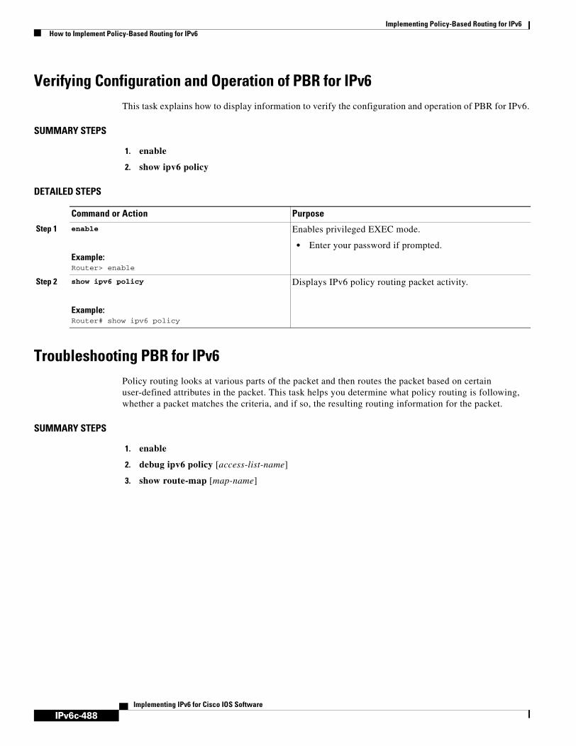
IPv6c-488
Implementing Policy-Based Routing for IPv6How to Implement Policy-Based Routing for IPv6
Implementing IPv6 for Cisco IOS Software
Verifying Configuration and Operation of PBR for IPv6This task explains how to display information to verify the configuration and operation of PBR for IPv6.
SUMMARY STEPS
1. enable
2. show ipv6 policy
DETAILED STEPS
Troubleshooting PBR for IPv6Policy routing looks at various parts of the packet and then routes the packet based on certain user-defined attributes in the packet. This task helps you determine what policy routing is following, whether a packet matches the criteria, and if so, the resulting routing information for the packet.
SUMMARY STEPS
1. enable
2. debug ipv6 policy [access-list-name]
3. show route-map [map-name]
Command or Action Purpose
Step 1 enable
Example:Router> enable
Enables privileged EXEC mode.
• Enter your password if prompted.
Step 2 show ipv6 policy
Example:Router# show ipv6 policy
Displays IPv6 policy routing packet activity.

IPv6c-489
Implementing Policy-Based Routing for IPv6Configuration Examples for Policy-Based Routing for IPv6
Implementing IPv6 for Cisco IOS Software
DETAILED STEPS
Examples
This section provides the following output examples:
• Sample Output for the show ipv6 policy Command, page 489
• Sample Output for the show route-map Command, page 489
Sample Output for the show ipv6 policy Command
The show ipv6 policy command displays PBR configuration, as shown in the following example:
Router# show ipv6 policy
Interface RoutemapEthernet0/0 src-1
Sample Output for the show route-map Command
The show route-map command displays specific route-map information, such as a count of policy matches:
Router# show route-map
route-map bill, permit, sequence 10 Match clauses: Set clauses: Policy routing matches:0 packets, 0 bytes
Configuration Examples for Policy-Based Routing for IPv6The following sections provide PBR for IPv6 configuration examples:
• Enabling PBR on an Interface: Example, page 490
• Enabling Local PBR for IPv6: Example, page 490
Command or Action Purpose
Step 1 enable
Example:Router> enable
Enables privileged EXEC mode.
• Enter your password if prompted.
Step 2 debug ipv6 policy [access-list-name]
Example:Router# debug ipv6 policy
Displays IPv6 policy routing packet activity.
Step 3 show route-map [map-name]
Example:Router# show route-map
Displays all route maps configured or only the one specified.

IPv6c-490
Implementing Policy-Based Routing for IPv6Additional References
Implementing IPv6 for Cisco IOS Software
Enabling PBR on an Interface: ExampleIn the following example, a route map named pbr-dest-1 is created and configured, specifying packet match criteria and desired policy-route action. Then, PBR is enabled on Ethernet interface 0/0.
ipv6 access-list match-dest-1 permit ipv6 any 2001:0db8:2001:1760::/32
route-map pbr-dest-1 permit 10 match ipv6 address match-dest-1 set interface Ethernet 0/0
interface Ethernet0/0 ipv6 policy-route-map interactive
Enabling Local PBR for IPv6: ExampleIn the following example, packets with a destination IPv6 address matching that allowed by access list pbr-src-90 are sent to the router at IPv6 address 2001:0db8:2003:1::95:
ipv6 access-list src-90 permit ipv6 host 2001:0db8:2003::90 2001:0db8:2001:1000::/64
route-map pbr-src-90 permit 10 match ipv6 address src-90 set ipv6 next-hop 2001:0db8:2003:1::95
ipv6 local policy route-map pbr-src-90
Additional ReferencesThe following sections provide references related to implementing PBR for IPv6.
Related Documents
Related Topic Document Title
QoS for IPv6 Implementing QoS for IPv6
Multicast Border Gateway Protocol (BGP) for IPv6 Implementing Multiprotocol BGP for IPv6
Access control lists for IPv6 Implementing Security for IPv6
IPv6 supported feature list Start Here: Cisco IOS Software Release Specifics for IPv6 Features
IPv6 commands: complete command syntax, command mode, defaults, usage guidelines, and examples
IPv6 for Cisco IOS Command Reference
IPv4 Policy-Based Routing Cisco IOS Quality of Service Solutions Configuration Guide
IPv4 configuration and command reference information
Cisco IOS Release 12.4 Configuration Guides and Command References

IPv6c-491
Implementing Policy-Based Routing for IPv6Additional References
Implementing IPv6 for Cisco IOS Software
MIBs
Technical Assistance
MIBs MIBs Link
No new or modified MIBs are required for this feature. To locate and download MIBs for selected platforms, Cisco IOS releases, and feature sets, use Cisco MIB Locator found at the following URL:
http://www.cisco.com/go/mibs
Description Link
The Cisco Technical Support website contains thousands of pages of searchable technical content, including links to products, technologies, solutions, technical tips, and tools. Registered Cisco.com users can log in from this page to access even more content.
http://www.cisco.com/techsupport

IPv6c-492
Implementing Policy-Based Routing for IPv6Additional References
Implementing IPv6 for Cisco IOS Software

IPv6c-493Implementing IPv6 for Cisco IOS Software
Implementing QoS for IPv6 for Cisco IOS Software
This module provides tasks for implementing quality of service (QoS) features in IPv6 environments, specifically the application of the Differentiated Services (DiffServ) QoS features to IPv6 packets.
Finding Support Information for Platforms and Cisco IOS Software Images
Use Cisco Feature Navigator to find information about platform support and Cisco IOS software image support. Access Cisco Feature Navigator at http://www.cisco.com/go/fn. You must have an account on Cisco.com. If you do not have an account or have forgotten your username or password, click Cancel at the login dialog box and follow the instructions that appear.
Contents• Prerequisites for QoS for IPv6, page 493
• Restrictions for QoS for IPv6, page 494
• Information About QoS in IPv6, page 494
• How to Implement QoS for IPv6, page 497
• Configuration Examples for Implementing QoS for IPv6, page 507
• Additional References, page 508
Prerequisites for QoS for IPv6Table 22 identifies the earliest release for each early-deployment train in which the feature became available.
Table 22 Minimum Required Cisco IOS Release
FeatureMinimum Required Cisco IOS Release by Release Train
IPv6 quality of service (QoS) 12.2(13)T, 12.3, 12.3(2)T, 12.0(28)S1, 12.4, 12.4(2)T
Modular QoS command-line interface (MQC) packet classification
12.2(13)T, 12.3, 12.3(2)T, 12.4, 12.4(2)T

IPv6c-494
Implementing QoS for IPv6 for Cisco IOS SoftwareRestrictions for QoS for IPv6
Implementing IPv6 for Cisco IOS Software
Restrictions for QoS for IPv6The following QoS features are not supported for managing IPv6 traffic:
• Compressed Real-Time Protocol (CRTP)
• Network-based application recognition (NBAR)
• Committed access rate (CAR)
• Priority queueing (PQ)
• Custom queueing (CQ)
Platform-Specific Information and Restrictions
IPv6 QoS is supported on Cisco 12000 series Internet routers in Cisco IOS Release 12.0(28)S. Certain features of IPv6 QoS are not supported in Release 12.0(28)S. These features include packet classification.
Information About QoS in IPv6The following sections provide information about the QoS features available for managing IPv6 traffic:
• Implementation Strategy for QoS for IPv6, page 495
• Packet Classification in IPv6, page 495
• Policies and Class-Based Packet Marking in IPv6 Networks, page 496
• Congestion Management in IPv6 Networks, page 496
• Congestion Avoidance for IPv6 Traffic, page 496
• Traffic Policing in IPv6 Environments, page 496
MQC traffic shaping 12.2(13)T, 12.3, 12.3(2)T, 12.0(28)S1, 12.4, 12.4(2)T
MQC traffic policing 12.2(13)T, 12.3, 12.3(2)T, 12.0(28)S1, 12.4, 12.4(2)T
MQC packet marking/remarking 12.2(13)T, 12.3, 12.3(2)T, 12.0(28)S1, 12.4, 12.4(2)T
Queueing 12.2(13)T, 12.3, 12.3(2)T, 12.0(28)S1, 12.4, 12.4(2)T
MQC WRED-based drop 12.2(13)T, 12.3, 12.3(2)T, 12.0(28)S1, 12.4, 12.4(2)T
1. Feature is supported on Cisco 12000 series Internet routers in Cisco IOS Release 12.0(28)S.
Table 22 Minimum Required Cisco IOS Release
FeatureMinimum Required Cisco IOS Release by Release Train

IPv6c-495
Implementing QoS for IPv6 for Cisco IOS SoftwareInformation About QoS in IPv6
Implementing IPv6 for Cisco IOS Software
Implementation Strategy for QoS for IPv6IPv6 packets are forwarded by paths that are different from those for IPv4. QoS features supported for IPv6 environments include packet classification, queueing, traffic shaping, WRED, class-based packet marking, and policing of IPv6 packets. These features are available at both the process switching and Cisco Express Forwarding (CEF) switching paths of IPv6.
All of the QoS features available for IPv6 environments are managed from the modular QoS command-line interface (CLI). The modular QoS CLI allows you to define traffic classes, create and configure traffic policies (policy maps), and then attach those traffic policies to interfaces. A detailed description of the modular QoS CLI can be found in the Cisco IOS Quality of Service Configuration Guide.
To implement QoS in networks running IPv6, follow the same steps that you would follow to implement QoS in networks running only IPv4. At a very high level, the basic steps for implementing QoS are as follows:
1. Know which applications in your network need QoS.
2. Understand the characteristics of the applications so that you can make decisions about which QoS features would be appropriate.
3. Know your network topology so that you know how link layer header sizes are affected by changes and forwarding.
4. Create classes based on the criteria you establish for your network. In particular, if the same network is also carrying IPv4 traffic along with IPv6, decide if you want to treat both of them the same way or treat them separately and specify match criteria accordingly. If you want to treat them the same, use match statements such as match precedence, match dscp, set precedence, and set dscp. If you want to treat them separately, add match criteria such as match protocol ip and match protocol ipv6 in a match-all class map.
5. Create a policy to mark each class.
6. Work from the edge toward the core in applying QoS features.
7. Build the policy to treat the traffic.
8. Apply the policy.
Packet Classification in IPv6Packet classification is available with both process and CEF switching path. Classification can be based on IPv6 precedence, differentiated services control point (DSCP), and other IPv6 protocol-specific values that can be specified in IPv6 access lists in addition to other non-IPv6 protocol specific values such as COS, packet length, and QOS group. Once you determine which applications need QoS, you can create classes based on the characteristics of the applications. You can use a variety of match criteria to classify traffic. You can combine various match criteria to segregate, isolate, and differentiate traffic.
The enhancements to the modular QoS CLI allow you to create matches on precedence, DSCP, and IPv6 access group values in both IPv4 and IPv6 packets. The match command has been modified so that matches can be made on DSCP values and precedence for both IP and IPv6 packets. See “Using the

IPv6c-496
Implementing QoS for IPv6 for Cisco IOS SoftwareInformation About QoS in IPv6
Implementing IPv6 for Cisco IOS Software
Match Criteria to Manage IPv6 Traffic Flows” section on page 162 for configuration guidelines and see the match dscp and match precedence command descriptions. See the “Enhanced Packet Marking” document in Release 12.2(13)T for details of the modular QoS CLI enhancements.
Policies and Class-Based Packet Marking in IPv6 NetworksYou can create a policy to mark each class of traffic with appropriate priority values, using either DSCP or precedence. Class-based marking allows you to set the IPv6 precedence and DSCP values for traffic management. The traffic is marked as it enters the router on the ingress interface. The markings are used to treat the traffic (forward, queue) as it leaves the router on the egress interface. Always mark and treat the traffic as close as possible to its source.
Use the set dscp and set precedence commands for packet marking. These commands have been modified to handle both IPv4 and IPv6 traffic. See the “Specifying Marking Criteria for IPv6 Packets” section on page 497 for configuration guidelines for using these commands. See the set dscp and set precedence command pages for detailed descriptions of the commands.
Congestion Management in IPv6 NetworksOnce you have marked the traffic, you can use the markings to build a policy and classify traffic on the rest of the network segments. If you keep the policy simple (no more than about four classes), it will be easier to manage. Class-based and flow-based queueing are supported for IPv6. The processes and tasks use the same commands and arguments to configure various queueing options for both IP and IPv6. Refer to the Cisco IOS Quality of Service Configuration Guide for configuration and usage instructions of queueing features.
Congestion Avoidance for IPv6 TrafficWRED implements the RED-based drop policy on the packets that are likely to overflow the limits of Class-based Weighted Fair Queueing (CBWFQ). WRED supports class-based and flow-based (using DSCP or precedence values) queueing. The WRED commands apply to both IPv4 and IPv6 with no changes. Refer to the Cisco IOS Quality of Service Solutions Configuration Guide for information about these QoS features.
Traffic Policing in IPv6 EnvironmentsCongestion management for IPv6 is similar to its implementation for IP packets, and the commands used to configure queueing and traffic shaping features for IPv6 environments are the same commands as those used for IP. Traffic shaping allows you to limit the packet dequeue rate by holding additional packets in the queues and forwarding them as specified by parameters configured for traffic shaping features. Traffic shaping uses flow-based queueing by default. CBWFQ can be used to classify and prioritize the packets. Class-Based Policer and Generic Traffic Shaping (GTS) or Frame Relay Traffic Shaping (FRTS) can be used for conditioning and policing traffic.
Although no changes to existing configuration or command usage for policing are required for use in IPv6 environments, the police command has been enhanced to mark both IPv4 and IPv6 packets when the following keyword options are used in confirm action, exceed action, and violate action:
• set-dscp-transmit

IPv6c-497
Implementing QoS for IPv6 for Cisco IOS SoftwareHow to Implement QoS for IPv6
Implementing IPv6 for Cisco IOS Software
• set-precedence-transmit
Refer to the Cisco IOS Quality of Service Solutions Configuration Guide for information about these features and Cisco IOS Quality of Service Solutions Command Reference for detailed descriptions of these commands and their options.
How to Implement QoS for IPv6These configuration tasks describe how to classify traffic with match criteria and use the match criteria to manage traffic flows. The following sections are included:
• Restrictions for Classifying Traffic in IPv6 Networks, page 497 (required)
• Specifying Marking Criteria for IPv6 Packets, page 497 (required)
• Using the Match Criteria to Manage IPv6 Traffic Flows, page 498 (required)
• Verifying Packet Marking Criteria, page 500 (optional)
Restrictions for Classifying Traffic in IPv6 NetworksExcept for the modifications to the match dscp and match precedence commands (which are described in this document) and the addition of the IPv6-specific match access-group name command, the functionality of all of the match commands is the same for both IPv4 and IPv6.
The match access-group xxx command for matching numbered access lists is not supported. Note that the match ip rtp command for matching RTP port ranges works only for IPv4 packets.
The set cos and match cos commands for 802.1Q (dot1Q) interfaces are supported only for CEF-switched packets. Process-switched packets, such as router-generated packets, are not marked when these options are used.
The set cos and match cos for ISL links is not supported for CEF-switched packets. Process switching is not supported with these options.
Specifying Marking Criteria for IPv6 PacketsThe following task uses the set precedence command to establish the match criteria (or mark the packets) that will be used later to match packets for classifying network traffic. Commands used for this purpose are set precedence and set dscp. These commands have been modified to accommodate marking of IPv6 packets.
SUMMARY STEPS
1. enable
2. configure terminal
3. policy map policy-map-name
4. class {class-name | class-default}
5. set precedence cos table table-map-name
or
set dscp cos table table-map-name

IPv6c-498
Implementing QoS for IPv6 for Cisco IOS SoftwareHow to Implement QoS for IPv6
Implementing IPv6 for Cisco IOS Software
DETAILED STEPS
Troubleshooting Tips
Confirm That CEF Is Enabled
Use the show cef interface, show ipv6 cef, show ipv6 interface neighbors, and show interface statistics commands to confirm that CEF is enabled and that packets are being CEF switched.
Confirm That Packets Are CEF Switched
Use the show policy-map interface command to display per-interface, per-policy CEF-switching statistics.
Using the Match Criteria to Manage IPv6 Traffic FlowsOnce you have defined the traffic classes and established the policies, you can use the match commands to match the traffic to the policies that you establish. You can use multiple match statements. Depending on the type of class, you can specify whether to match all classes or any of the classes.
Command or Action Purpose
Step 1 enable
Example:Router> enable
Enables such as privileged EXEC mode.
• Enter your password if prompted.
Step 2 configure terminal
Example:Router# configure terminal
Enters global configuration mode.
Step 3 policy map policy-map-name
Example:Router(config)# policy map policy1
Creates a policy map using the specified name and enters QoS policy-map configuration mode.
• Enter name of policy map you want to create.
Step 4 class {class-name | class-default}
Example:Router(config-pmap)# class class-default
Specifies the treatment for traffic of specified class (or the default class) and enters QoS policy-map class configuration mode.
Step 5 set precedence cos table table-map-name
or
set dscp cos table table-map-name
Example:Router(config-pmap-c)# set dscp cos table table-map1Router(config-pmap-c)# set precedence cos table table-map1
Sets the precedence value. This example is based on the CoS value (and action) defined in the specified table map. The CLI is applicable to both IPv4 and IPv6 packets. However, the action occurs only on the packets that matched the criteria specified for the class name used in Step 4.
• Both precedence and DSCP cannot be changed in the same packets.
• Sets the DSCP value based on the CoS value (and action) defined in the specified table map.

IPv6c-499
Implementing QoS for IPv6 for Cisco IOS SoftwareHow to Implement QoS for IPv6
Implementing IPv6 for Cisco IOS Software
SUMMARY STEPS
1. enable
2. configure terminal
3. class-map {class-name | class-default}
4. match precedence precedence-value [precedence-value precedence-value]
or
match access-group name ipv6-access-group
or
match [ip] dscp dscp-value [dscp-value dscp-value dscp-value dscp-value dscp-value dscp-value dscp-value]
DETAILED STEPS
Command or Action Purpose
Step 1 enable
Example:Router> enable
Enables such as privileged EXEC mode.
• Enter your password if prompted.
Step 2 configure terminal
Example:Router# configure terminal
Enters global configuration mode.
Step 3 class-map {class-name | class-default}
Example:Router(config-pmap-c)# class clsl
Creates the specified class and enters QoS class-map configuration mode.
Step 4 match precedence precedence-value [precedence-value precedence-value]
or
match access-group name ipv6-access-group
or
match [ip] dscp dscp-value [dscp-value dscp-value dscp-value dscp-value dscp-value dscp-value dscp-value]
Example:Router(config-pmap-c)# match precedence 5Router(config-pmap-c)# match access-group name ipv6aclRouter(config-pmap-c)# match ip dscp 15
Matches the precedence value. The precedence applies to both IPv4 and IPv6 packets.
or
Specifies the name of an IPv6 access list against whose contents packets are checked to determine if they belong to the traffic class.
or
Identifies a specific IP DSCP value as a match criterion.

IPv6c-500
Implementing QoS for IPv6 for Cisco IOS SoftwareHow to Implement QoS for IPv6
Implementing IPv6 for Cisco IOS Software
Configuration Examples for Using the Match Criteria to Manage IPv6 Traffic Flows
The following example shows how to use the match precedence command to manage IPv6 traffic flows.
Router# configure terminal
Enter configuration commands, one per line. End with CNTL/Z.Router(config)# class-m c1Router(config-cmap)# match precedence 5Router(config-cmap)# end
Router#Router(config)# policy p1Router(config-pmap)# class c1Router(config-pmap-c)# police 10000 conform set-prec-trans 4Router(config-pmap-c)# end
Router#
Verifying Packet Marking CriteriaTo verify that packet marking is working as expected, use the show policy command. The interesting information from the output of this command is the difference in the number of total packets versus the number of packets marked. Explanations of the counters follow the example.
Router# show policy p1
Policy Map p1 Class c1 police 10000 1500 1500 conform-action set-prec-transmit 4 exceed-action drop
Router# configure terminalEnter configuration commands, one per line. End with CNTL/Z.Router(config)# interface serial 4/1Router(config-if)# service out p1Router(config-if)# endRouter#Router# show policy interface s4/1 Serial4/1 Service-policy output: p1 Class-map: c1 (match-all) 0 packets, 0 bytes 5 minute offered rate 0 bps, drop rate 0 bps Match: precedence 5 police: 10000 bps, 1500 limit, 1500 extended limit conformed 0 packets, 0 bytes; action: set-prec-transmit 4 exceeded 0 packets, 0 bytes; action: drop conformed 0 bps, exceed 0 bps violate 0 bps
Class-map: class-default (match-any) 10 packets, 1486 bytes 5 minute offered rate 0 bps, drop rate 0 bps Match: any
Interpreting Packet Counters in show policy-map interface Command Output
During periods of transmit congestion at the outgoing interface, packets arrive faster than the interface can send them. It is helpful to know how to interpret the output of the show policy-map interface command, which is useful for monitoring the results of a service-policy created with Cisco’s modular QoS CLI.

IPv6c-501
Implementing QoS for IPv6 for Cisco IOS SoftwareHow to Implement QoS for IPv6
Implementing IPv6 for Cisco IOS Software
Congestion typically occurs when a fast ingress interface feeds a relatively slow egress interface. A common congestion point is a branch-office router with an Ethernet port facing the LAN and a serial port facing the WAN. Users on the LAN segment are generating 10 Mbps of traffic, which is being fed into a T1 with 1.5 Mbps of bandwidth.
Functionally, congestion is defined as filling the transmit ring on the interface (a ring is a special buffer control structure). Every interface supports a pair of rings: a receive ring for receiving packets and a transmit ring for sending packets. The size of the rings varies with the interface controller and with the bandwidth of the interface or virtual circuit (VC). As in the following example, use the show atm vc vcd command to display the value of the transmit ring on a PA-A3 ATM port adapter.
Router# show atm vc 3
ATM5/0.2: VCD: 3, VPI: 2, VCI: 2 VBR-NRT, PeakRate: 30000, Average Rate: 20000, Burst Cells: 94 AAL5-LLC/SNAP, etype:0x0, Flags: 0x20, VCmode: 0x0 OAM frequency: 0 second(s) PA TxRingLimit: 10 InARP frequency: 15 minutes(s) Transmit priority 2 InPkts: 0, OutPkts: 0, InBytes: 0, OutBytes: 0 InPRoc: 0, OutPRoc: 0 InFast: 0, OutFast: 0, InAS: 0, OutAS: 0 InPktDrops: 0, OutPktDrops: 0 CrcErrors: 0, SarTimeOuts: 0, OverSizedSDUs: 0 OAM cells received: 0 OAM cells sent: 0 Status: UP
Cisco IOS software (also referred to as the Layer 3 processor) and the interface driver use the transmit ring when moving packets to the physical media. The two processors collaborate in the following way:
• The interface sends packets according to the interface rate or a shaped rate.
• The interface maintains a hardware queue or transmit ring, where it stores the packets waiting for transmission onto the physical wire.
• When the hardware queue or transmit ring fills, the interface provides explicit back pressure to the Layer 3 processor system. It notifies the Layer 3 processor to stop dequeuing packets to the interface’s transmit ring because the transmit ring is full. The Layer 3 processor now stores the excess packets in the Layer 3 queues.
• When the interface sends the packets on the transmit ring and empties the ring, it once again has sufficient buffers available to store the packets. It releases the back pressure, and the Layer 3 processor dequeues new packets to the interface.
The most important aspect of this communication system is that the interface recognizes that its transmit ring is full and throttles the receipt of new packets from the Layer 3 processor system. Thus, when the interface is congested, the drop decision is moved from a random, last-in, first-dropped decision in the first in, first out (FIFO) queue of the transmit ring to a differentiated decision based on IP-level service policies implemented by the Layer 3 processor.
Number of Packets and Packets Matched
Service policies apply only to packets stored in the Layer 3 queues. Table 23 illustrates which packets sit in the Layer 3 queue. Locally generated packets are always process switched and are delivered first to the Layer 3 queue before being passed on to the interface driver. Fast-switched and CEF-switched packets are delivered directly to the transmit ring and sit in the L3 queue only when the transmit ring is full.
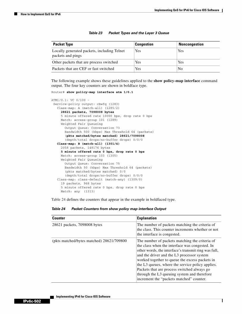
IPv6c-502
Implementing QoS for IPv6 for Cisco IOS SoftwareHow to Implement QoS for IPv6
Implementing IPv6 for Cisco IOS Software
Table 23 Packet Types and the Layer 3 Queue
The following example shows these guidelines applied to the show policy-map interface command output. The four key counters are shown in boldface type.
Router# show policy-map interface atm 1/0.1
ATM1/0.1: VC 0/100 - Service-policy output: cbwfq (1283)
Class-map: A (match-all) (1285/2) 28621 packets, 7098008 bytes 5 minute offered rate 10000 bps, drop rate 0 bps Match: access-group 101 (1289) Weighted Fair Queueing
Output Queue: Conversation 73 Bandwidth 500 (kbps) Max Threshold 64 (packets) (pkts matched/bytes matched) 28621/7098008 (depth/total drops/no-buffer drops) 0/0/0
Class-map: B (match-all) (1301/4) 2058 packets, 148176 bytes 5 minute offered rate 0 bps, drop rate 0 bps Match: access-group 103 (1305) Weighted Fair Queueing
Output Queue: Conversation 75 Bandwidth 50 (kbps) Max Threshold 64 (packets) (pkts matched/bytes matched) 0/0 (depth/total drops/no-buffer drops) 0/0/0
Class-map: class-default (match-any) (1309/0) 19 packets, 968 bytes 5 minute offered rate 0 bps, drop rate 0 bps Match: any (1313)
Table 24 defines the counters that appear in the example in boldfaced type.
Packet Type Congestion Noncongestion
Locally generated packets, including Telnet packets and pings
Yes Yes
Other packets that are process switched Yes Yes
Packets that are CEF or fast switched Yes No
Table 24 Packet Counters from show policy map interface Output
Counter Explanation
28621 packets, 7098008 bytes The number of packets matching the criteria of the class. This counter increments whether or not the interface is congested.
(pkts matched/bytes matched) 28621/709800 The number of packets matching the criteria of the class when the interface was congested. In other words, the interface’s transmit ring was full, and the driver and the L3 processor system worked together to queue the excess packets in the L3 queues, where the service policy applies. Packets that are process switched always go through the L3 queuing system and therefore increment the “packets matched” counter.

IPv6c-503
Implementing QoS for IPv6 for Cisco IOS SoftwareHow to Implement QoS for IPv6
Implementing IPv6 for Cisco IOS Software
Without congestion, there is no need to queue any excess packets. When congestion occurs, packets, including CEF- and fast-switched packets, might go into the Layer 3 queue. If you use congestion management features, packets accumulating at an interface are queued until the interface is free to send them; they are then scheduled according to their assigned priority and the queueing mechanism configured for the interface.
Normally, the packets counter is much larger than the packets matched counter. If the values of the two counters are nearly equal, then the interface is receiving a large number of process-switched packets or is heavily congested. Both of these conditions should be investigated to ensure optimal packet forwarding.
Conversation Number Allocation
Routers allocate conversation numbers for the queues that are created when the service policy is applied. The following example shows the queues and related information.
Router# show policy-map interface s1/0.1 dlci 100
Serial1/0.1: DLCI 100 - output : mypolicy Class voice Weighted Fair Queueing Strict Priority Output Queue: Conversation 72 Bandwidth 16 (kbps) Packets Matched 0 (pkts discards/bytes discards) 0/0 Class immediate-data Weighted Fair Queueing Output Queue: Conversation 73 Bandwidth 60 (%) Packets Matched 0 (pkts discards/bytes discards/tail drops) 0/0/0 mean queue depth: 0 drops: class random tail min-th max-th mark-prob 0 0 0 64 128 1/10 1 0 0 71 128 1/10 2 0 0 78 128 1/10 3 0 0 85 128 1/10 4 0 0 92 128 1/10 5 0 0 99 128 1/10 6 0 0 106 128 1/10
Class-map: B (match-all) (1301/4) These numbers define an internal ID used with the CISCO-CLASS-BASED-QOS-MIB Management Information Base (MIB). They no longer appear in the show policy-map command output in current releases of Cisco IOS.
5 minute offered rate 0 bps, drop rate 0 bps Use the load-interval command to change this value and make it a more instantaneous value. The lowest value is 30 seconds; however, statistics displayed in the show policy-map interface command output are updated every 10 seconds. Because the command effectively provides a snapshot at a specific moment, the statistics may not reflect a temporary change in queue size.
Table 24 Packet Counters from show policy map interface Output
Counter Explanation

IPv6c-504
Implementing QoS for IPv6 for Cisco IOS SoftwareHow to Implement QoS for IPv6
Implementing IPv6 for Cisco IOS Software
7 0 0 113 128 1/10 rsvp 0 0 120 128 1/10 Class priority-data Weighted Fair Queueing Output Queue: Conversation 74 Bandwidth 40 (%) Packets Matched 0 Max Threshold 64 (packets) (pkts discards/bytes discards/tail drops) 0/0/0 Class class-default Weighted Fair Queueing Flow Based Fair Queueing Maximum Number of Hashed Queues 64 Max Threshold 20 (packets)
Information reported for each class includes the following:
• Class definition
• Queueing method applied
• Output Queue Conversation number
• Bandwidth used
• Number of packets discarded
• Number of bytes discarded
• Number of packets dropped
The class-default class is the default class to which traffic is directed, if that traffic does not satisfy the match criteria of other classes whose policy is defined in the policy map. The fair-queue command allows you to specify the number of dynamic queues into which IP flows are sorted and classified. Alternately, routers allocate a default number of queues derived from the bandwidth on the interface or VC. Supported values in either case are a power of two, in a range from 16 to 4096.
Table 25 lists the default values for interfaces and for ATM permanent virtual circuits (PVCs).
Table 26 lists the default number of dynamic queues in relation to ATM PVC bandwidth.
Table 25 Default Number of Dynamic Queues as a Function of Interface Bandwidth
Bandwidth Range Number of Dynamic Queues
Less than or equal to 64 kbps 16
More than 64 kbps and less than or equal to 128 kbps
32
More than 128 kbps and less than or equal to 256 kbps
64
More than 256 kbps and less than or equal to 512 kbps
128
More than 512 kbps 256
Table 26 Default Number of Dynamic Queues as a Function of ATM PVC Bandwidth
Bandwidth Range Number of Dynamic Queues
Less than or equal to 128 kbps 16
More than 128 kbps and less than or equal to 512 kbps
32

IPv6c-505
Implementing QoS for IPv6 for Cisco IOS SoftwareHow to Implement QoS for IPv6
Implementing IPv6 for Cisco IOS Software
Based on the number of reserved queues for WFQ, Cisco IOS software assigns a conversation or queue number as shown in the Table 9.
Confirming the Service Policy
This task tests the packets matched counter and your service policy. Ensure that the traffic flow matches the input or output parameter of the policy. For example, downloading a file from an FTP server generates congestion in the receive direction because the server sends large MTU-sized frames, and the client PC returns small acknowledgments (ACKs).
SUMMARY STEPS
1. Simulate congestion
2. enable
3. configure terminal
4. interface atm slot/0. subinterface-number {multipoint | point-to-point}
5. ip address ip-address mask [secondary]
6. pvc [name] vpi/vci [ces | ilmi | qsaal | smds]
7. tx-ring-limit ring-limit
8. service-policy {input | output} policy-map-name
More than 512 kbps and less than or equal to 2000 kbps
64
More than 2000 kbps and less than or equal to 8000 kbps
128
More than 8000 kbps 256
Table 26 Default Number of Dynamic Queues as a Function of ATM PVC Bandwidth
Bandwidth Range Number of Dynamic Queues
Table 27 Conversation Numbers Assigned to Queues
Number Type of Traffic
1 to 256 General flow-based traffic queues. Traffic that does not match to a user-created class will match to class-default and one of the flow-based queues.
257 to 263 Reserved for Cisco Discovery Protocol (formerly known as CDP) and for packets marked with an internal high-priority flag.
264 Reserved queue for the priority class (classes configured with the priority command). Look for the “Strict Priority” value for the class in the show policy-map interface output. The priority queue uses a conversation ID equal to the number of dynamic queues, plus 8.
265 and higher Queues for user-created classes.

IPv6c-506
Implementing QoS for IPv6 for Cisco IOS SoftwareHow to Implement QoS for IPv6
Implementing IPv6 for Cisco IOS Software
DETAILED STEPS
Command or Action Purpose
Step 1 Simulate congestion with an extended ping using a large ping size and a large number of pings. Also, try downloading a large file from an FTP server.
The file constitutes “disturbing” data and fills the interface bandwidth.
Step 2 enable
Example:Router> enable
Enables privileged EXEC mode.
• Enter your password if prompted.
Step 3 configure terminal
Example:Router# configure terminal
Enters global configuration mode.
Step 4 interface atm slot/0. subinterface-number {multipoint | point-to-point}
Example:Router(config)# interface atm 1/0.1 point-to-point}
Enters interface configuration mode.
Step 5 ip address ip-address mask [secondary]
Example:Router(config-if)# ip address 10.1.1.1 255.255.255.0
Specifies the IP address of the interface you want to test.
Step 6 pvc [name] vpi/vci [ces | ilmi | qsaal | smds]
Example:Router(config-if)# pvc cisco 0/5
Creates or assigns a name to an ATM PVC, optionally specifies the encapsulation type on an ATM PVC, and enters interface-ATM-VC configuration mode.
Step 7 tx-ring-limit ring-limit
Example:Router(config-if-atm-vc)# tx-ring-limit 10
Reduces the size of the transmit ring of the interface. Lowering this value accelerates the use of the QoS in the Cisco IOS software.
• Specify the ring limit as the number of packets for 2600 and 3600 series routers, or as the number of memory particles for 7200 and 7500 series routers.
Step 8 service-policy {input | output} policy-map-name
Example:Router(config-if-atm-vc)# service-policy output policy9
Attaches a policy map to an input interface or VC, or an output interface or VC, to be used as the service policy for that interface or VC.
• Note that the packets matched counter is a part of queueing feature and is available only on service policies attached in output direction.

IPv6c-507
Implementing QoS for IPv6 for Cisco IOS SoftwareConfiguration Examples for Implementing QoS for IPv6
Implementing IPv6 for Cisco IOS Software
Configuration Examples for Implementing QoS for IPv6This section provides the following configuration examples:
• Verification of CEF Switching: Example, page 507
• Matching DSCP Value: Example, page 507
Verification of CEF Switching: ExampleThe following is sample output from the show cef interface detail command for Ethernet interface 1/0/0. Use this command to verify that CEF switching is enabled for policy decisions to occur. Notice that the display shows that CEF switching is enabled.
Router# show cef interface Ethernet 1/0/0 detail Ethernet1/0/0 is up (if_number 9) Corresponding hwidb fast_if_number 9 Corresponding hwidb firstsw->if_number 9 Internet address is 10.2.61.8/24 ICMP redirects are always sent Per packet load-sharing is disabled IP unicast RPF check is disabled Inbound access list is not set Outbound access list is not set IP policy routing is disabled Hardware idb is Ethernet1/0/0 Fast switching type 1, interface type 5 IP Distributed CEF switching enabled IP Feature Fast switching turbo vector IP Feature CEF switching turbo vector Input fast flags 0x0, Output fast flags 0x0 ifindex 7(7) Slot 1 Slot unit 0 VC -1 Transmit limit accumulator 0x48001A82 (0x48001A82) IP MTU 1500
Matching DSCP Value: ExampleThe following example shows how to configure the service policy called priority50 and attach service policy priority50 to an interface. In this example, the match dscp command includes the optional ip keyword, meaning that the match is for IPv4 packets only. The class map called ipdscp15 will evaluate all packets entering interface Fast Ethernet 1/0/0. If the packet is an IPv4 packet and has a DSCP value of 15, the packet will be treated as priority traffic and will be allocated with bandwidth of 50 kbps.
Router(config)# class-map ipdscp15Router(config-cmap)# match ip dscp 15Router(config)# exitRouter(config)# policy-map priority50Router(config-pmap)# class ipdscp15Router(config-pmap-c)# priority 50Router(config-pmap-c)# exitRouter(config-pmap)# exitRouter(config)# interface fa1/0/0Router(config-if)# service-policy input priority55
To match on IPv6 packets only, use the match dscp command without the ip keyword preceded by the match protocol command. Ensure that the class map has the match-all attribute (which is the default).
IPv6c-508
Implementing QoS for IPv6 for Cisco IOS SoftwareAdditional References
Implementing IPv6 for Cisco IOS Software
Router(config)# class-map ipdscp15Router(config-cmap)# match protocol ipv6Router(config-cmap)# match dscp 15Router(config)# exit
To match packets on both IPv4 and IPv6 protocols, use the match dscp command:
Router(config)# class-map ipdscp15Router(config-cmap)# match dscp 15Router(config)# exit
Additional ReferencesThe following sections provide references related to QoS for IPv6:
Related Documents
MIBs
Related Topic Document Title
QoS features Cisco IOS Quality of Service Solutions Configuration Guide, Release 12.4
Cisco IOS Quality of Service Solutions Command Reference, Release 12.4
Enhancements for packet marking Enhanced Packet Marking
IPv4 configuration and command reference information Cisco IOS Release 12.4 Configuration Guides and Command References
MIBs MIBs Link
No new or modified MIBs are supported by this feature, and support for existing MIBs has not been modified by this feature.
To locate and download MIBs for selected platforms, Cisco IOS releases, and feature sets, use Cisco MIB Locator found at the following URL:
http://www.cisco.com/go/mibs

IPv6c-509
Implementing QoS for IPv6 for Cisco IOS SoftwareAdditional References
Implementing IPv6 for Cisco IOS Software
RFCs
Technical Assistance
RFCs Title
RFC 2474 Definition of the Differentiated Services Field (DS Field) in the IPv4 and IPv6 Headers
RFC 2475 An Architecture for Differentiated Services Framework
RFC 2597 Assured Forwarding PHB
RFC 2598 An Expedited Forwarding PHB
RFC 2640 Internet Protocol, Version 6 Specification
RFC 2697 A Single Rate Three Color Marker
RFC 2698 A Two Rate Three Color Marker
Description Link
The Cisco Technical Support website contains thousands of pages of searchable technical content, including links to products, technologies, solutions, technical tips, and tools. Registered Cisco.com users can log in from this page to access even more content.
http://www.cisco.com/techsupport

IPv6c-510
Implementing QoS for IPv6 for Cisco IOS SoftwareAdditional References
Implementing IPv6 for Cisco IOS Software

IPv6c-511Implementing IPv6 for Cisco IOS Software
Implementing Tunneling for IPv6
This module describes how to configure overlay tunneling techniques used by the Cisco IOS software to support the transition from IPv4-only networks to integrated IPv4- and IPv6-based networks. Tunneling encapsulates IPv6 packets in IPv4 packets and uses the IPv4 network as a link-layer mechanism.
Finding Support Information for Platforms and Cisco IOS Software Images
Use Cisco Feature Navigator to find information about platform support and Cisco IOS software image support. Access Cisco Feature Navigator at http://www.cisco.com/go/fn. You must have an account on Cisco.com. If you do not have an account or have forgotten your username or password, click Cancel at the login dialog box and follow the instructions that appear.
Contents• Prerequisites for Implementing Tunneling for IPv6, page 511
• Restrictions for Implementing Tunneling for IPv6, page 512
• Information About Implementing Tunneling for IPv6, page 512
• How to Implement Tunneling for IPv6, page 517
• Configuration Examples for Implementing Tunneling for IPv6, page 527
• Where to Go Next, page 531
• Additional References, page 532
Prerequisites for Implementing Tunneling for IPv6This document assumes that you are familiar with IPv4. Refer to the publications referenced in the “Related Documents” section for IPv4 configuration and command reference information. Table 28 identifies the earliest release for each early-deployment train in which the feature became available.

IPv6c-512
Implementing Tunneling for IPv6Restrictions for Implementing Tunneling for IPv6
Implementing IPv6 for Cisco IOS Software
Restrictions for Implementing Tunneling for IPv6In Cisco IOS Release 12.0(21)ST and Cisco IOS Release 12.0(22)S and earlier releases, the Cisco 12000 series gives a very low priority to the processing of IPv6 tunneled packets. Therefore, we strongly recommend that you limit the use of IPv6 tunnels on the Cisco 12000 series using these releases to topologies that sustain a low level of network traffic and require a minimal amount of process-switching resources. IPv6 manually configured tunnel traffic in Cisco IOS Release 12.0(23)S is processed in software on the CPU of the line card, instead of in the Route Processor (RP) in the Cisco 12000 router, resulting in enhanced performance.
Information About Implementing Tunneling for IPv6To configure tunneling for IPv6, you need to understand the following concepts:
• Overlay Tunnels for IPv6, page 513
• IPv6 Manually Configured Tunnels, page 514
• GRE/IPv4 Tunnel Support for IPv6 Traffic, page 515
• GRE/CLNS Tunnel Support for IPv4 and IPv6 Packets, page 515
• Automatic 6to4 Tunnels, page 515
• Automatic IPv4-Compatible IPv6 Tunnels, page 516
• ISATAP Tunnels, page 516
Table 28 Minimum Required Cisco IOS Release
Feature Minimum Required Cisco IOS Release by Release Train
Automatic 6-to-4 Tunnels 12.2(2)T, 12.0(21)ST, 12.0(22)S, 12.2(14)S, 12.3, 12.3(2)T, 12.4, 12.4(2)T, 12.2(28)SB
Automatic IPv4-Compatible Tunnels 12.2(2)T, 12.0(21)ST, 12.0(22)S, 12.2(14)S, 12.3, 12.3(2)T, 12.4, 12.4(2)T, 12.2(28)SB
IPv6 manually configured tunnels 12.2(2)T, 12.0(21)ST, 12.0(23)S, 12.2(14)S, 12.3, 12.3(2)T, 12.4, 12.4(2)T, 12.2(28)SB
IPv6 over IPv4 GRE tunnels 12.2(2)T, 12.0(21)ST, 12.0(22)S, 12.2(14)S, 12.3, 12.3(2)T, 12.4, 12.4(2)T, 12.2(28)SB
IPv6 over UTI using a tunnel line card1
1. Supported on the Cisco 12000 series Internet router only.
12.0(23)S
ISATAP tunnels 12.2(14)S, 12.3(2)T, 12.4, 12.4(2)T, 12.2(28)SB
GRE Tunnels over an IPv6 Network 12.3(7)T, 12.4, 12.4(2)T, 12.2(30)S
IPv4 over IPv6 Tunnels 12.3(7)T, 12.4, 12.4(2)T, 12.2(30)S
IPv6 over IPv6 Tunnels 12.3(7)T, 12.4, 12.4(2)T, 12.2(30)S
CLNS Support for GRE Tunneling of IPv4 and IPv6 in CTunnels
12.3(7)T, 12.2(25)S, 12.4, 12.4(2)T, 12.2(28)SB

IPv6c-513
Implementing Tunneling for IPv6Information About Implementing Tunneling for IPv6
Implementing IPv6 for Cisco IOS Software
Overlay Tunnels for IPv6Overlay tunneling encapsulates IPv6 packets in IPv4 packets for delivery across an IPv4 infrastructure (a core network or the Internet). (See Figure 37.) By using overlay tunnels, you can communicate with isolated IPv6 networks without upgrading the IPv4 infrastructure between them. Overlay tunnels can be configured between border routers or between a border router and a host; however, both tunnel endpoints must support both the IPv4 and IPv6 protocol stacks. Cisco IOS IPv6 supports the following types of overlay tunneling mechanisms:
• Manual
• Generic routing encapsulation (GRE)
• IPv4-compatible
• 6to4
• Intra-Site Automatic Tunnel Addressing Protocol (ISATAP)
Figure 37 Overlay Tunnels)
Note Overlay tunnels reduce the maximum transmission unit (MTU) of an interface by 20 octets (assuming the basic IPv4 packet header does not contain optional fields). A network using overlay tunnels is difficult to troubleshoot. Therefore, overlay tunnels connecting isolated IPv6 networks should not be considered as a final IPv6 network architecture. The use of overlay tunnels should be considered as a transition technique toward a network that supports both the IPv4 and IPv6 protocol stacks or just the IPv6 protocol stack.
Use Table 29 to help you determine which type of tunnel you want to configure to carry IPv6 packets over an IPv4 network.
5268
5
IPv6host
IPv6host
IPv6network
IPv6 header IPv6 data
IPv6network
Dual-stackrouter
Dual-stackrouter
IPv4
IPv4 header IPv6 headerTunnel: IPv6 in IPv4 packet
IPv6 data
IPv6 header IPv6 data
Table 29 Suggested Usage of Tunnel Types to Carry IPv6 Packets over an IPv4 Network
Tunneling Type Suggested Usage Usage Notes
Manual Simple point-to-point tunnels that can be used within a site or between sites
Can carry IPv6 packets only.
GRE- and IPv4-compatible
Simple point-to-point tunnels that can be used within a site or between sites
Can carry IPv6, Connectionless Network Service (CLNS), and many other types of packets.

IPv6c-514
Implementing Tunneling for IPv6Information About Implementing Tunneling for IPv6
Implementing IPv6 for Cisco IOS Software
Individual tunnel types are discussed in detail in this document. We recommend that you review and understand the information about the specific tunnel type that you want to implement. When you are familiar with the type of tunnel you need, see Table 30 for a summary of the tunnel configuration parameters that you may find useful.
IPv6 Manually Configured TunnelsA manually configured tunnel is equivalent to a permanent link between two IPv6 domains over an IPv4 backbone. The primary use is for stable connections that require regular secure communication between two edge routers or between an end system and an edge router, or for connection to remote IPv6 networks.
An IPv6 address is manually configured on a tunnel interface, and manually configured IPv4 addresses are assigned to the tunnel source and the tunnel destination. The host or router at each end of a configured tunnel must support both the IPv4 and IPv6 protocol stacks. Manually configured tunnels can be configured between border routers or between a border router and a host. Cisco Express Forwarding switching can be used for IPv6 manually configured tunnels, or Cisco Express Forwarding switching can be disabled if process switching is needed.
IPv4-compatible
Point-to-multipoint tunnels Uses the ::/96 prefix. We do not now recommend using this tunnel type.
6to4 Point-to-multipoint tunnels that can be used to connect isolated IPv6 sites
Sites use addresses from the 2002::/16 prefix.
ISATAP Point-to-multipoint tunnels that can be used to connect systems within a site
Sites can use any IPv6 unicast addresses.
Table 29 Suggested Usage of Tunnel Types to Carry IPv6 Packets over an IPv4 Network
Tunneling Type Suggested Usage Usage Notes
Table 30 Tunnel Configuration Parameters by Tunneling Type
Tunneling Type
Tunnel Configuration Parameter
Tunnel ModeTunnel Source Tunnel Destination Interface Prefix or Address
Manual ipv6ip An IPv4 address, or a reference to an interface on which IPv4 is configured.
An IPv4 address. An IPv6 address.
GRE/IPv4 gre ip An IPv4 address. An IPv6 address.
IPv4-compatible
ipv6ip auto-tunnel
Not required. These are all point-to-multipoint tunneling types. The IPv4 destination address is calculated, on a per-packet basis, from the IPv6 destination.
Not required. The interface address is generated as ::tunnel-source/96.
6to4 ipv6ip 6to4 An IPv6 address. The prefix must embed the tunnel source IPv4 address
ISATAP ipv6ip isatap An IPv6 prefix in modified eui-64 format. The IPv6 address is generated from the prefix and the tunnel source IPv4 address.

IPv6c-515
Implementing Tunneling for IPv6Information About Implementing Tunneling for IPv6
Implementing IPv6 for Cisco IOS Software
GRE/IPv4 Tunnel Support for IPv6 TrafficIPv6 traffic can be carried over IPv4 GRE tunnels using the standard GRE tunneling technique that is designed to provide the services necessary to implement any standard point-to-point encapsulation scheme. As in IPv6 manually configured tunnels, GRE tunnels are links between two points, with a separate tunnel for each link. The tunnels are not tied to a specific passenger or transport protocol, but in this case carry IPv6 as the passenger protocol with the GRE as the carrier protocol and IPv4 or IPv6 as the transport protocol.
The primary use of GRE tunnels is for stable connections that require regular secure communication between two edge routers or between an edge router and an end system. The edge routers and the end systems must be dual-stack implementations.
GRE has a protocol field that identifies the passenger protocol. GRE tunnels allow Intermediate System-to-Intermediate System (IS-IS) or IPv6 to be specified as a passenger protocol, which allows both IS-IS and IPv6 traffic to run over the same tunnel. If GRE did not have a protocol field, it would be impossible to distinguish whether the tunnel was carrying IS-IS or IPv6 packets. The GRE protocol field is why it is desirable that you tunnel IS-IS and IPv6 inside GRE.
GRE/CLNS Tunnel Support for IPv4 and IPv6 PacketsGRE tunneling of IPv4 and IPv6 packets through CLNS networks enables Cisco CLNS Tunnels (CTunnels) to interoperate with networking equipment from other vendors. This feature provides compliance with RFC 3147.
The optional GRE services defined in header fields, such as checksums, keys, and sequencing, are not supported. Any packet received requesting such services will be dropped.
Refer to CLNS Support for GRE Tunneling of IPv4 and IPv6 Packets, Release 12.3(7)T for details about this feature, and Cisco IOS Network Protocols 3: ISO CLNS, Release 12.4 for information about CTunnels.
Automatic 6to4 TunnelsAn automatic 6to4 tunnel allows isolated IPv6 domains to be connected over an IPv4 network to remote IPv6 networks. The key difference between automatic 6to4 tunnels and manually configured tunnels is that the tunnel is not point-to-point; it is point-to-multipoint. In automatic 6to4 tunnels, routers are not configured in pairs because they treat the IPv4 infrastructure as a virtual nonbroadcast multiaccess (NBMA) link. The IPv4 address embedded in the IPv6 address is used to find the other end of the automatic tunnel.
An automatic 6to4 tunnel may be configured on a border router in an isolated IPv6 network, which creates a tunnel on a per-packet basis to a border router in another IPv6 network over an IPv4 infrastructure. The tunnel destination is determined by the IPv4 address of the border router extracted from the IPv6 address that starts with the prefix 2002::/16, where the format is 2002:border-router-IPv4-address::/48. Following the embedded IPv4 address are 16 bits that can be used to number networks within the site. The border router at each end of a 6to4 tunnel must support both the IPv4 and IPv6 protocol stacks. 6to4 tunnels are configured between border routers or between a border router and a host.
The simplest deployment scenario for 6to4 tunnels is to interconnect multiple IPv6 sites, each of which has at least one connection to a shared IPv4 network. This IPv4 network could be the global Internet or a corporate backbone. The key requirement is that each site have a globally unique IPv4 address; the

IPv6c-516
Implementing Tunneling for IPv6Information About Implementing Tunneling for IPv6
Implementing IPv6 for Cisco IOS Software
Cisco IOS software uses this address to construct a globally unique 6to4/48 IPv6 prefix. As with other tunnel mechanisms, appropriate entries in a Domain Name System (DNS) that map between hostnames and IP addresses for both IPv4 and IPv6 allow the applications to choose the required address.
Automatic IPv4-Compatible IPv6 TunnelsAutomatic IPv4-compatible tunnels use IPv4-compatible IPv6 addresses. IPv4-compatible IPv6 addresses are IPv6 unicast addresses that have zeros in the high-order 96 bits of the address, and an IPv4 address in the low-order 32 bits. They can be written as 0:0:0:0:0:0:A.B.C.D or ::A.B.C.D, where “A.B.C.D” represents the embedded IPv4 address.
The tunnel destination is automatically determined by the IPv4 address in the low-order 32 bits of IPv4-compatible IPv6 addresses. The host or router at each end of an IPv4-compatible tunnel must support both the IPv4 and IPv6 protocol stacks. IPv4-compatible tunnels can be configured between border-routers or between a border-router and a host. Using IPv4-compatible tunnels is an easy method to create tunnels for IPv6 over IPv4, but the technique does not scale for large networks.
Note IPv4-compatible tunnels were initially supported for IPv6, but are being deprecated. Cisco recommends that you use the IPv6 ISATAP tunneling technique.
ISATAP TunnelsISATAP is an automatic overlay tunneling mechanism that uses the underlying IPv4 network as a NBMA link layer for IPv6. ISATAP is designed for transporting IPv6 packets within a site where a native IPv6 infrastructure is not yet available; for example, when sparse IPv6 hosts are deployed for testing. ISATAP tunnels allow individual IPv4 or IPv6 dual-stack hosts within a site to communicate with other such hosts on the same virtual link, basically creating an IPv6 network using the IPv4 infrastructure.
The ISATAP router provides standard router advertisement network configuration support for the ISATAP site. This feature allows clients to automatically configure themselves as they would do if they were connected to an Ethernet. It can also be configured to provide connectivity out of the site. ISATAP uses a well-defined IPv6 address format composed of any unicast IPv6 prefix (/64), which can be link local, or global (including 6to4 prefixes), enabling IPv6 routing locally or on the Internet. The IPv4 address is encoded in the last 32 bits of the IPv6 address, enabling automatic IPv6-in-IPv4 tunneling.
Although the ISATAP tunneling mechanism is similar to other automatic tunneling mechanisms, such as IPv6 6to4 tunneling, ISATAP is designed for transporting IPv6 packets within a site, not between sites.
ISATAP uses unicast addresses that include a 64-bit IPv6 prefix and a 64-bit interface identifier. The interface identifier is created in modified EUI-64 format in which the first 32 bits contain the value 000:5EFE to indicate that the address is an IPv6 ISATAP address. Table 31 describes an ISATAP address format.
Table 31 IPv6 ISATAP Address Format
64 Bits 32 Bits 32 Bits
link local or global IPv6 unicast prefix
0000:5EFE IPv4 address of the ISATAP link

IPv6c-517
Implementing Tunneling for IPv6How to Implement Tunneling for IPv6
Implementing IPv6 for Cisco IOS Software
As shown in Table 31, an ISATAP address consists of an IPv6 prefix and the ISATAP interface identifier. This interface identifier includes the IPv4 address of the underlying IPv4 link. The following example shows what an actual ISATAP address would look like if the prefix is 2001:0DB8:1234:5678::/64 and the embedded IPv4 address is 10.173.129.8. In the ISATAP address, the IPv4 address is expressed in hexadecimal as 0AAD:8108.
Example:
2001:0DB8:1234:5678:0000:5EFE:0AAD:8108
IPv6 IPSec Site-to-Site Protection Using Virtual Tunnel InterfaceThe IPv6 IPSec feature provides IPv6 crypto site-to-site protection of all types of IPv6 unicast and multicast traffic using native IPSec IPv6 encapsulation. The IPSec virtual tunnel interface (VTI) feature provides this function, using IKE as the management protocol.
An IPSec VTI supports native IPSec tunneling and includes most of the properties of a physical interface. The IPSec VTI alleviates the need to apply crypto maps to multiple interfaces and provides a routable interface.
The IPSec VTI allows IPv6 routers to work as security gateways, establish IPSec tunnels between other security gateway routers, and provide crypto IPSec protection for traffic from internal network when being transmitting across the public IPv6 Internet.
For further information on VTIs, see the Implementing IPSec on IPv6 module.
How to Implement Tunneling for IPv6The following sections explain how to implement tunneling for IPv6:
• Configuring Manual IPv6 Tunnels, page 517
• Configuring GRE IPv6 Tunnels, page 519
• Configuring 6to4 Tunnels, page 520
• Configuring IPv4-Compatible IPv6 Tunnels, page 522
• Configuring ISATAP Tunnels, page 523
Configuring Manual IPv6 TunnelsThis task explains how to configure a IPv6 overlay tunnel manually.
Prerequisites
With manually configured IPv6 tunnels, an IPv6 address is configured on a tunnel interface, and manually configured IPv4 addresses are assigned to the tunnel source and the tunnel destination. The host or router at each end of a configured tunnel must support both the IPv4 and IPv6 protocol stacks.
SUMMARY STEPS
1. enable

IPv6c-518
Implementing Tunneling for IPv6How to Implement Tunneling for IPv6
Implementing IPv6 for Cisco IOS Software
2. configure terminal
3. interface tunnel tunnel-number
4. ipv6 address ipv6-prefix/prefix-length [eui-64]
5. tunnel source {ip-address | interface-type interface-number}
6. tunnel destination ip-address
7. tunnel mode ipv6ip
DETAILED STEPS
Command or Action Purpose
Step 1 enable
Example:Router> enable
Enables privileged EXEC mode.
• Enter your password if prompted.
Step 2 configure terminal
Example:Router# configure terminal
Enters global configuration mode.
Step 3 interface tunnel tunnel-number
Example:Router(config)# interface tunnel 0
Specifies a tunnel interface and number, and enters interface configuration mode.
Step 4 ipv6 address ipv6-prefix/prefix-length [eui-64]
Example:Router(config-if)# ipv6 address 3ffe:b00:c18:1::3/127
Specifies the IPv6 network assigned to the interface and enables IPv6 processing on the interface.
Note Refer to the Configuring Basic Connectivity for IPv6 module for more information on configuring IPv6 addresses.
Step 5 tunnel source {ip-address | interface-type interface-number}
Example:Router(config-if)# tunnel source ethernet 0
Specifies the source IPv4 address or the source interface type and number for the tunnel interface.
• If an interface is specified, the interface must be configured with an IPv4 address.
Step 6 tunnel destination ip-address
Example:Router(config-if)# tunnel destination 192.168.30.1
Specifies the destination IPv4 address or hostname for the tunnel interface.
Step 7 tunnel mode ipv6ip
Example:Router(config-if)# tunnel mode ipv6ip
Specifies a manual IPv6 tunnel.
Note The tunnel mode ipv6ip command specifies IPv6 as the passenger protocol and IPv4 as both the encapsulation and transport protocol for the manual IPv6 tunnel.

IPv6c-519
Implementing Tunneling for IPv6How to Implement Tunneling for IPv6
Implementing IPv6 for Cisco IOS Software
What to Do Next
Proceed to the “Verifying IPv6 Tunnel Configuration and Operation” section on page 525.
Configuring GRE IPv6 TunnelsThis task explains how to configure a GRE tunnel on an IPv6 network. GRE tunnels can be configured to run over an IPv6 network layer and to transport IPv6 packets in IPv6 tunnels and IPv4 packets in IPv6 tunnels.
Prerequisites
When GRE IPv6 tunnels are configured, IPv6 addresses are assigned to the tunnel source and the tunnel destination. The tunnel interface can have either IPv4 or IPv6 addresses assigned (this is not shown in the task). The host or router at each end of a configured tunnel must support both the IPv4 and IPv6 protocol stacks.
SUMMARY STEPS
1. enable
2. configure terminal
3. interface tunnel tunnel-number
4. ipv6 address ipv6-prefix/prefix-length [eui-64]
5. tunnel source {ip-address | ipv6-address | interface-type interface-number}
6. tunnel destination {host-name | ip-address | ipv6-address}
7. tunnel mode {aurp | cayman | dvmrp | eon | gre | gre multipoint | gre ipv6 | ipip [decapsulate-any] | iptalk | ipv6 | mpls | nos}
DETAILED STEPS
Command or Action Purpose
Step 1 enable
Example:Router> enable
Enables privileged EXEC mode.
• Enter your password if prompted.
Step 2 configure terminal
Example:Router# configure terminal
Enters global configuration mode.
Step 3 interface tunnel tunnel-number
Example:Router(config)# interface tunnel 0
Specifies a tunnel interface and number, and enters interface configuration mode.

IPv6c-520
Implementing Tunneling for IPv6How to Implement Tunneling for IPv6
Implementing IPv6 for Cisco IOS Software
What to Do Next
Proceed to the “Verifying IPv6 Tunnel Configuration and Operation” section on page 525.
Configuring 6to4 TunnelsThis task explains how to configure a 6to4 overlay tunnel.
Prerequisites
With 6to4 tunnels, the tunnel destination is determined by the border router IPv4 address, which is concatenated to the prefix 2002::/16 in the format 2002:border-router-IPv4-address::/48. The border router at each end of a 6to4 tunnel must support both the IPv4 and IPv6 protocol stacks.
Restrictions
The configuration of only one IPv4-compatible tunnel and one 6to4 IPv6 tunnel is supported on a router. If you choose to configure both of those tunnel types on the same router, we strongly recommend that they do not share the same tunnel source.
The reason that a 6to4 tunnel and an IPv4-compatible tunnel cannot share an interface is that both of them are NBMA “point-to-multipoint” access links and only the tunnel source can be used to reorder the packets from a multiplexed packet stream into a single packet stream for an incoming interface. So when
Step 4 ipv6 address ipv6-prefix/prefix-length [eui-64]
Example:Router(config-if)# ipv6 address 3ffe:b00:c18:1::3/127
Specifies the IPv6 network assigned to the interface and enables IPv6 processing on the interface.
Note Refer to the Implementing Basic Connectivity for IPv6 module for more information on configuring IPv6 addresses.
Step 5 tunnel source {ip-address | ipv6-address | interface-type interface-number}
Example:Router(config-if)# tunnel source ethernet 0
Specifies the source IPv4 address or the source interface type and number for the tunnel interface.
• If an interface is specified, the interface must be configured with an IPv4 address.
Step 6 tunnel destination {host-name | ip-address | ipv6-address}
Example:Router(config-if)# tunnel destination 192.168.30.1
Specifies the destination IPv4 address or hostname for the tunnel interface.
Step 7 tunnel mode {aurp | cayman | dvmrp | eon | gre | gre multipoint | gre ipv6 | ipip [decapsulate-any] | iptalk | ipv6 | mpls | nos}
Example:Router(config-if)# tunnel mode gre ipv6
Specifies a GRE IPv6 tunnel.
Note The tunnel mode gre ipv6 command specifies GRE as the encapsulation protocol for the tunnel.
Command or Action Purpose

IPv6c-521
Implementing Tunneling for IPv6How to Implement Tunneling for IPv6
Implementing IPv6 for Cisco IOS Software
a packet with an IPv4 protocol type of 41 arrives on an interface, that packet is mapped to an IPv6 tunnel interface based on the IPv4 address. However, if both the 6to4 tunnel and the IPv4-compatible tunnel share the same source interface, the router is not able to determine the IPv6 tunnel interface to which it should assign the incoming packet.
IPv6 manually configured tunnels can share the same source interface because a manual tunnel is a “point-to-point” link, and both the IPv4 source and IPv4 destination of the tunnel are defined.
SUMMARY STEPS
1. enable
2. configure terminal
3. interface tunnel tunnel-number
4. ipv6 address ipv6-prefix/prefix-length [eui-64]
5. tunnel source {ip-address | interface-type interface-number}
6. tunnel mode ipv6ip 6to4
7. exit
8. ipv6 route ipv6-prefix/prefix-length tunnel tunnel-number
DETAILED STEPS
Command or Action Purpose
Step 1 enable
Example:Router> enable
Enables privileged EXEC mode.
• Enter your password if prompted.
Step 2 configure terminal
Example:Router# configure terminal
Enters global configuration mode.
Step 3 interface tunnel tunnel-number
Example:Router(config)# interface tunnel 0
Specifies a tunnel interface and number, and enters interface configuration mode.
Step 4 ipv6 address ipv6-prefix/prefix-length [eui-64]
Example:Router(config-if)# ipv6 address 2002:c0a8:6301:1::1/64
Specifies the IPv6 address assigned to the interface and enables IPv6 processing on the interface.
• The 32 bits following the initial 2002::/16 prefix correspond to an IPv4 address assigned to the tunnel source.
Note Refer to the Configuring Basic Connectivity for IPv6 module for more information on configuring IPv6 addresses.
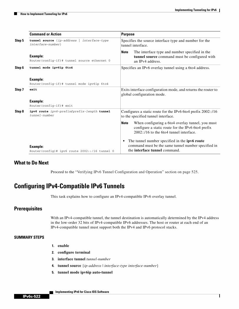
IPv6c-522
Implementing Tunneling for IPv6How to Implement Tunneling for IPv6
Implementing IPv6 for Cisco IOS Software
What to Do Next
Proceed to the “Verifying IPv6 Tunnel Configuration and Operation” section on page 525.
Configuring IPv4-Compatible IPv6 TunnelsThis task explains how to configure an IPv4-compatible IPv6 overlay tunnel.
Prerequisites
With an IPv4-compatible tunnel, the tunnel destination is automatically determined by the IPv4 address in the low-order 32 bits of IPv4-compatible IPv6 addresses. The host or router at each end of an IPv4-compatible tunnel must support both the IPv4 and IPv6 protocol stacks.
SUMMARY STEPS
1. enable
2. configure terminal
3. interface tunnel tunnel-number
4. tunnel source {ip-address | interface-type interface-number}
5. tunnel mode ipv6ip auto-tunnel
Step 5 tunnel source {ip-address | interface-type interface-number}
Example:Router(config-if)# tunnel source ethernet 0
Specifies the source interface type and number for the tunnel interface.
Note The interface type and number specified in the tunnel source command must be configured with an IPv4 address.
Step 6 tunnel mode ipv6ip 6to4
Example:Router(config-if)# tunnel mode ipv6ip 6to4
Specifies an IPv6 overlay tunnel using a 6to4 address.
Step 7 exit
Example:Router(config-if)# exit
Exits interface configuration mode, and returns the router to global configuration mode.
Step 8 ipv6 route ipv6-prefix/prefix-length tunnel tunnel-number
Example:Router(config)# ipv6 route 2002::/16 tunnel 0
Configures a static route for the IPv6 6to4 prefix 2002::/16 to the specified tunnel interface.
Note When configuring a 6to4 overlay tunnel, you must configure a static route for the IPv6 6to4 prefix 2002::/16 to the 6to4 tunnel interface.
• The tunnel number specified in the ipv6 route command must be the same tunnel number specified in the interface tunnel command.
Command or Action Purpose

IPv6c-523
Implementing Tunneling for IPv6How to Implement Tunneling for IPv6
Implementing IPv6 for Cisco IOS Software
DETAILED STEPS
What to Do Next
Proceed to the “Verifying IPv6 Tunnel Configuration and Operation” section on page 525.
Configuring ISATAP TunnelsThis task describes how to configure an ISATAP overlay tunnel.
Prerequisites
The tunnel source command used in the configuration of an ISATAP tunnel must point to an interface with an IPv4 address configured. The ISATAP IPv6 address and prefix (or prefixes) advertised are configured as for a native IPv6 interface. The IPv6 tunnel interface must be configured with a modified EUI-64 address because the last 32 bits in the interface identifier are constructed using the IPv4 tunnel source address.
SUMMARY STEPS
1. enable
2. configure terminal
Command or Action Purpose
Step 1 enable
Example:Router> enable
Enables privileged EXEC mode.
• Enter your password if prompted.
Step 2 configure terminal
Example:Router# configure terminal
Enters global configuration mode.
Step 3 interface tunnel tunnel-number
Example:Router(config)# interface tunnel 0
Specifies a tunnel interface and number, and enters interface configuration mode.
Step 4 tunnel source {ip-address | interface-type interface-number}
Example:Router(config-if)# tunnel source ethernet 0
Specifies the source interface type and number for the tunnel interface.
Note The interface type and number specified in the tunnel source command is configured with an IPv4 address only.
Step 5 tunnel mode ipv6ip auto-tunnel
Example:Router(config-if)# tunnel mode ipv6ip auto-tunnel
Specifies an IPv4-compatible tunnel using an IPv4-compatible IPv6 address.

IPv6c-524
Implementing Tunneling for IPv6How to Implement Tunneling for IPv6
Implementing IPv6 for Cisco IOS Software
3. interface tunnel tunnel-number
4. ipv6 address ipv6-prefix/prefix-length [eui-64]
5. no ipv6 nd suppress-ra
6. tunnel source {ip-address | interface-type interface-number}
7. tunnel mode ipv6ip isatap
DETAILED STEPS
What to Do Next
Proceed to the “Verifying IPv6 Tunnel Configuration and Operation” section on page 525.
Command or Action Purpose
Step 1 enable
Example:Router> enable
Enables privileged EXEC mode.
• Enter your password if prompted.
Step 2 configure terminal
Example:Router# configure terminal
Enters global configuration mode.
Step 3 interface tunnel tunnel-number
Example:Router(config)# interface tunnel 1
Specifies a tunnel interface and number, and enters interface configuration mode.
Step 4 ipv6 address ipv6-prefix/prefix-length [eui-64]
Example:Router(config-if)# ipv6 address 2001:0DB8:6301::/64 eui-64
Specifies the IPv6 address assigned to the interface and enables IPv6 processing on the interface.
Note Refer to the Configuring Basic Connectivity for IPv6 module for more information on configuring IPv6 addresses.
Step 5 no ipv6 nd suppress-ra
Example:Router(config-if)# no ipv6 nd suppress-ra
Sending of IPv6 router advertisements is disabled by default on tunnel interfaces. This command reenables the sending of IPv6 router advertisements to allow client autoconfiguration.
Step 6 tunnel source {ip-address | interface-type interface-number}
Example:Router(config-if)# tunnel source ethernet 1/0/1
Specifies the source interface type and number for the tunnel interface.
Note The interface type and number specified in the tunnel source command must be configured with an IPv4 address.
Step 7 tunnel mode ipv6ip isatap
Example:Router(config-if)# tunnel mode ipv6ip isatap
Specifies an IPv6 overlay tunnel using a ISATAP address.

IPv6c-525
Implementing Tunneling for IPv6How to Implement Tunneling for IPv6
Implementing IPv6 for Cisco IOS Software
Verifying IPv6 Tunnel Configuration and OperationThis optional task explains how to verify IPv6 tunnel configuration and operation. The commands contained in the task steps can be used in any sequence and may need to be repeated.
SUMMARY STEPS
1. enable
2. show interfaces tunnel number [accounting]
3. ping [protocol] destination
4. show ip route [address [mask]]
DETAILED STEPS
Examples
This section provides the following output examples:
• Sample Output for the show interfaces tunnel Command
• Sample Output for the ping Command
• Sample Output for the show ip route Command
• Sample Output for the ping Command
Sample Output for the show interfaces tunnel Command
This example uses a generic example suitable for both IPv6 manually configured tunnels and IPv6 over IPv4 GRE tunnels. In the example, two routers are configured to be endpoints of a tunnel. Router A has Ethernet interface 0/0 configured as tunnel interface 0 with an IPv4 address of 10.0.0.1 and an IPv6
Command or Action Purpose
Step 1 enable
Example:Router> enable
Enables privileged EXEC mode.
• Enter your password if prompted.
Step 2 show interfaces tunnel number [accounting]
Example:Router# show interfaces tunnel 0
(Optional) Displays tunnel interface information.
• Use the number argument to display information for a specified tunnel.
Step 3 ping [protocol] destination
Example:Router# ping 10.0.0.1
(Optional) Diagnoses basic network connectivity.
Step 4 show ip route [address [mask]]
Example:Router# show ip route 10.0.0.2
(Optional) Displays the current state of the routing table.
Note Only the syntax relevant for this task is shown.

IPv6c-526
Implementing Tunneling for IPv6How to Implement Tunneling for IPv6
Implementing IPv6 for Cisco IOS Software
prefix of 2001:0DB8:1111:2222::1/64. Router B has Ethernet interface 0/0 configured as tunnel interface 1 with an IPv4 address of 10.0.0.2 and an IPv6 prefix of 2001:0DB8:1111:2222::2/64. To verify that the tunnel source and destination addresses are configured, use the show interfaces tunnel command on Router A.
RouterA# show interfaces tunnel 0
Tunnel0 is up, line protocol is up Hardware is Tunnel MTU 1514 bytes, BW 9 Kbit, DLY 500000 usec, reliability 255/255, txload 1/255, rxload 1/255 Encapsulation TUNNEL, loopback not set Keepalive not set Tunnel source 10.0.0.1 (Ethernet0/0), destination 10.0.0.2, fastswitch TTL 255 Tunnel protocol/transport GRE/IP, key disabled, sequencing disabled Tunnel TTL 255 Checksumming of packets disabled, fast tunneling enabled Last input 00:00:14, output 00:00:04, output hang never Last clearing of "show interface" counters never Input queue: 0/75/0/0 (size/max/drops/flushes); Total output drops: 0 Queueing strategy: fifo Output queue :0/0 (size/max) 5 minute input rate 0 bits/sec, 0 packets/sec 5 minute output rate 0 bits/sec, 0 packets/sec 4 packets input, 352 bytes, 0 no buffer Received 0 broadcasts, 0 runts, 0 giants, 0 throttles 0 input errors, 0 CRC, 0 frame, 0 overrun, 0 ignored, 0 abort 8 packets output, 704 bytes, 0 underruns 0 output errors, 0 collisions, 0 interface resets 0 output buffer failures, 0 output buffers swapped out
Sample Output for the ping Command
To check that the local endpoint is configured and working, use the ping command on Router A:
RouterA# ping 2001:0DB8:1111:2222::2
Type escape sequence to abort.Sending 5, 100-byte ICMP Echos to 2001:0DB8:1111:2222::2, timeout is 2 seconds:!!!!!Success rate is 100 percent (5/5), round-trip min/avg/max = 20/20/20 ms
Sample Output for the show ip route Command
To check that a route exists to the remote endpoint address, use the show ip route command:
RouterA# show ip route 10.0.0.2
Routing entry for 10.0.0.0/24 Known via "connected", distance 0, metric 0 (connected, via interface) Routing Descriptor Blocks: * directly connected, via Ethernet0/0 Route metric is 0, traffic share count is 1
Sample Output for the ping Command
To check that the remote endpoint address is reachable, use the ping command on Router A.
Note The remote endpoint address may not be reachable using the ping command because of filtering, but the tunnel traffic may still reach its destination.

IPv6c-527
Implementing Tunneling for IPv6Configuration Examples for Implementing Tunneling for IPv6
Implementing IPv6 for Cisco IOS Software
RouterA# ping 10.0.0.2
Type escape sequence to abort.Sending 5, 100-byte ICMP Echos to 10.0.0.2, timeout is 2 seconds:!!!!!Success rate is 100 percent (5/5), round-trip min/avg/max = 20/21/28 ms
To check that the remote IPv6 tunnel endpoint is reachable, use the ping command again on Router A. The same note on filtering also applies to this example.
RouterA# ping 1::2
Type escape sequence to abort.Sending 5, 100-byte ICMP Echos to 1::2, timeout is 2 seconds:!!!!!Success rate is 100 percent (5/5), round-trip min/avg/max = 20/20/20 ms
These steps may be repeated at the other endpoint of the tunnel.
Configuration Examples for Implementing Tunneling for IPv6This section provides the following configuration examples:
• Configuring Manual IPv6 Tunnels: Example, page 527
• Configuring GRE Tunnels: Examples, page 528
• Configuring 6to4 Tunnels Example, page 530
• Configuring IPv4-Compatible IPv6 Tunnels Example, page 530
• Configuring ISATAP Tunnels Example, page 531
Configuring Manual IPv6 Tunnels: ExampleThe following example configures a manual IPv6 tunnel between router A and router B. In the example, tunnel interface 0 for both router A and router B is manually configured with a global IPv6 address. The tunnel source and destination addresses are also manually configured.
Router A Configurationinterface ethernet 0ip address 192.168.99.1 255.255.255.0
interface tunnel 0ipv6 address 3ffe:b00:c18:1::3/127tunnel source ethernet 0tunnel destination 192.168.30.1tunnel mode ipv6ip
Router B Configurationinterface ethernet 0ip address 192.168.30.1 255.255.255.0
interface tunnel 0ipv6 address 3ffe:b00:c18:1::2/127tunnel source ethernet 0tunnel destination 192.168.99.1tunnel mode ipv6ip
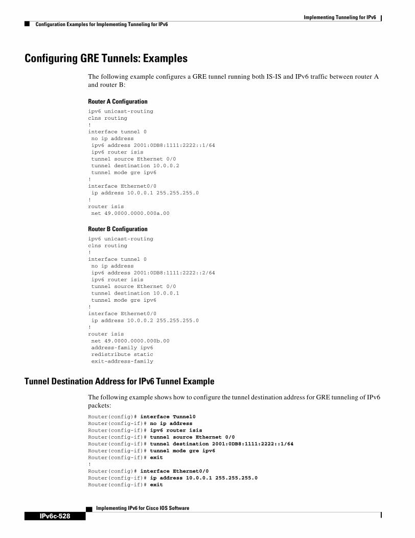
IPv6c-528
Implementing Tunneling for IPv6Configuration Examples for Implementing Tunneling for IPv6
Implementing IPv6 for Cisco IOS Software
Configuring GRE Tunnels: ExamplesThe following example configures a GRE tunnel running both IS-IS and IPv6 traffic between router A and router B:
Router A Configurationipv6 unicast-routingclns routing!interface tunnel 0 no ip address ipv6 address 2001:0DB8:1111:2222::1/64 ipv6 router isis tunnel source Ethernet 0/0 tunnel destination 10.0.0.2 tunnel mode gre ipv6!interface Ethernet0/0 ip address 10.0.0.1 255.255.255.0!router isis net 49.0000.0000.000a.00
Router B Configurationipv6 unicast-routingclns routing!interface tunnel 0 no ip address ipv6 address 2001:0DB8:1111:2222::2/64 ipv6 router isis tunnel source Ethernet 0/0 tunnel destination 10.0.0.1 tunnel mode gre ipv6!interface Ethernet0/0 ip address 10.0.0.2 255.255.255.0!router isis net 49.0000.0000.000b.00 address-family ipv6 redistribute static exit-address-family
Tunnel Destination Address for IPv6 Tunnel Example
The following example shows how to configure the tunnel destination address for GRE tunneling of IPv6 packets:
Router(config)# interface Tunnel0Router(config-if)# no ip addressRouter(config-if)# ipv6 router isis Router(config-if)# tunnel source Ethernet 0/0Router(config-if)# tunnel destination 2001:0DB8:1111:2222::1/64Router(config-if)# tunnel mode gre ipv6Router(config-if)# exit!Router(config)# interface Ethernet0/0Router(config-if)# ip address 10.0.0.1 255.255.255.0Router(config-if)# exit

IPv6c-529
Implementing Tunneling for IPv6Configuration Examples for Implementing Tunneling for IPv6
Implementing IPv6 for Cisco IOS Software
!Router(config)# ipv6 unicast-routing
Router(config)# router isis Router(config)# net 49.0000.0000.000a.00
Configuring CTunnels in GRE mode to Carry IPv6 Packets in CLNS: ExampleThe following example configures a GRE CTunnel running both IS-IS and IPv6 traffic between router A and router B in a CLNS network. The ctunnel mode gre command allows tunneling between Cisco and third-party networking devices and carries both IPv4 and IPv6 traffic.
The ctunnel mode gre command provides a method of tunneling compliant with RFC 3147 and should allow tunneling between Cisco equipment and third-party networking devices.
Router A
ipv6 unicast-routing
clns routing
interface ctunnel 102
ipv6 address 2001:0DB8:1111:2222::1/64 ctunnel destination 49.0001.2222.2222.2222.00 ctunnel mode gre
interface Ethernet0/1 clns router isis
router isis net 49.0001.1111.1111.1111.00
Router B
ipv6 unicast-routing
clns routing
interface ctunnel 201 ipv6 address 2001:0DB8:1111:2222::2/64 ctunnel destination 49.0001.1111.1111.1111.00 ctunnel mode gre
interface Ethernet0/1 clns router isis
router isis net 49.0001.2222.2222.2222.00
To turn off the GRE mode and restore the CTunnel to the default Cisco encapsulation routing only between endpoints on Cisco equipment, use either the no ctunnel mode command or the ctunnel mode cisco command. The following example shows the same configuration modified to transport only IPv4 traffic.

IPv6c-530
Implementing Tunneling for IPv6Configuration Examples for Implementing Tunneling for IPv6
Implementing IPv6 for Cisco IOS Software
Configuring 6to4 Tunnels ExampleThe following example configures a 6to4 tunnel on a border router in an isolated IPv6 network. The IPv4 address is 192.168.99.1, which translates to the IPv6 prefix of 2002:c0a8:6301::/48. The IPv6 prefix is subnetted into 2002:c0a8:6301::/64 for the tunnel interface: 2002:c0a8:6301:1::/64 for the first IPv6 network, and 2002:c0a8:6301:2::/64 for the second IPv6 network. The static route ensures that any other traffic for the IPv6 prefix 2002::/16 is directed to tunnel interface 0 for automatic tunneling.
interface Ethernet0 description IPv4 uplink ip address 192.168.99.1 255.255.255.0!interface Ethernet1 description IPv6 local network 1 ipv6 address 2002:c0a8:6301:1::1/64 !interface Ethernet2 description IPv6 local network 2 ipv6 address 2002:c0a8:6301:2::1/64 !interface Tunnel0 description IPv6 uplink no ip address ipv6 address 2002:c0a8:6301::1/64 tunnel source Ethernet 0 tunnel mode ipv6ip 6to4!ipv6 route 2002::/16 tunnel 0
Configuring IPv4-Compatible IPv6 Tunnels ExampleThe following example configures an IPv4-compatible IPv6 tunnel that allows Border Gateway Protocol (BGP) to run between a number of routers without having to configure a mesh of manual tunnels. Each router has a single IPv4-compatible tunnel, and multiple BGP sessions can run over each tunnel, one to each neighbor. Ethernet interface 0 is used as the tunnel source. The tunnel destination is automatically determined by the IPv4 address in the low-order 32 bits of an IPv4-compatible IPv6 address. Specifically, the IPv6 prefix 0:0:0:0:0:0 is concatenated to an IPv4 address (in the format 0:0:0:0:0:0:A.B.C.D or ::A.B.C.D) to create the IPv4-compatible IPv6 address. Ethernet interface 0 is configured with a global IPv6 address and an IPv4 address (the interface supports both the IPv6 and IPv4 protocol stacks).
Multiprotocol BGP is used in the example to exchange IPv6 reachability information with the peer 10.67.0.2. The IPv4 address of Ethernet interface 0 is used in the low-order 32 bits of an IPv4-compatible IPv6 address and is also used as the next-hop attribute. Using an IPv4-compatible IPv6 address for the BGP neighbor allows the IPv6 BGP session to be automatically transported over an IPv4-compatible tunnel.
interface tunnel 0 tunnel source Ethernet 0 tunnel mode ipv6ip auto-tunnel
interface ethernet 0 ip address 10.27.0.1 255.255.255.0 ipv6 address 3000:2222::1/64
router bgp 65000 no synchronization no bgp default ipv4-unicast

IPv6c-531
Implementing Tunneling for IPv6Where to Go Next
Implementing IPv6 for Cisco IOS Software
neighbor ::10.67.0.2 remote-as 65002
address-family ipv6 neighbor ::10.67.0.2 activate neighbor ::10.67.0.2 next-hop-self network 2001:2222:d00d:b10b::/64
Configuring ISATAP Tunnels ExampleThe following example shows the tunnel source defined on Ethernet 0 and the tunnel mode command used to configure the ISATAP tunnel. Router advertisements are enabled to allow client autoconfiguration.
ipv6 unicast-routinginterface tunnel 1tunnel source ethernet 0tunnel mode ipv6ip isatapipv6 address 2001:0DB8::/64 eui-64no ipv6 nd suppress-raexit
Where to Go Next• If you have configured an automatic 6to4 tunnel you can design your IPv6 network around the /48
6to4 prefix you have created from your IPv4 address.
• If you want to implement routing protocols, refer to the Implementing RIP for IPv6, Implementing IS-IS for IPv6, Implementing OSPF for IPv6, or Implementing Multiprotocol BGP for IPv6 module.
• If you want to implement security features for your IPv6 network, refer to the Implementing Security for IPv6 module.

IPv6c-532
Implementing Tunneling for IPv6Additional References
Implementing IPv6 for Cisco IOS Software
Additional ReferencesThe following sections provide references related to implementing tunneling for IPv6.
Related Documents
Standards
MIBs
RFCs
Related Topic Document Title
IPSec VTIs Implementing IPSec on IPv6
IPv4 tunneling configuration tasks “Configuring Logical Interfaces” chapter in the Cisco IOS Interface Configuration Guide, Release 12.4
IPv4 tunneling commands: complete command syntax, command mode, defaults, usage guidelines, and examples
Cisco IOS Interface Command Reference, Release 12.4
IPv6 supported feature list Start Here: Cisco IOS Software Release Specifics for IPv6 Features
IPv6 commands: complete command syntax, command mode, defaults, usage guidelines, and examples
IPv6 for Cisco IOS Command Reference
IPv4 configuration and command reference information
Cisco IOS Release 12.4 Configuration Guides and Command References
Standards Title
No new or modified standards are supported by this feature, and support for existing standards has not been modified by this feature.
—
MIBs MIBs Link
No new or modified MIBs are supported by this feature, and support for existing MIBs has not been modified by this feature.
To locate and download MIBs for selected platforms, Cisco IOS releases, and feature sets, use Cisco MIB Locator found at the following URL:
http://www.cisco.com/go/mibs
RFCs Title
RFC 2473 Generic Packet Tunneling in IPv6 Specification
RFC 2893 Transition Mechanisms for IPv6 Hosts and Routers
RFC 3056 Connection of IPv6 Domains via IPv4 Clouds
RFC 4214 Intra-Site Automatic Tunnel Addressing Protocol (ISATAP)

IPv6c-533
Implementing Tunneling for IPv6Additional References
Implementing IPv6 for Cisco IOS Software
Technical Assistance
Description Link
The Cisco Technical Support website contains thousands of pages of searchable technical content, including links to products, technologies, solutions, technical tips, and tools. Registered Cisco.com users can log in from this page to access even more content.
http://www.cisco.com/techsupport

IPv6c-534
Implementing Tunneling for IPv6Additional References
Implementing IPv6 for Cisco IOS Software

IPv6c-535Implementing IPv6 for Cisco IOS Software
BC Cisco IOS Bridging and IBM Networking Configuration Guide
DC Cisco IOS Dial Technologies Configuration Guide
FC Cisco IOS Configuration Fundamentals Configuration Guide
IC Cisco IOS Interface Configuration Guide
IPC Cisco IOS IP Routing Configuration Guide
IPv6C Implementing IPv6 for Cisco IOS Software
MWC Cisco IOS Mobile Wireless Configuration Guide
P2C Cisco IOS AppleTalk and Novell IPX Configuration Guide
P3C Cisco IOS Apollo Domain, Banyan VINES, DECnet, ISO CLNS, and XNS Configuration Guide
QC Cisco IOS Quality of Service Solutions Configuration Guide
SC Cisco IOS Security Configuration Guide
TC Cisco IOS Terminal Services Configuration Guide
VC Cisco IOS Voice, Video, and Fax Configuration Guide
WC Cisco IOS Wide-Area Networking Configuration Guide
XC Cisco IOS Switching Services Configuration Guide
I N D E X
Symbols
/prefix-length argument, defined IPv6c-58
Numerics
6PE multipath IPv6c-121
6PE router topology, figure IPv6c-229
6PE verification
CEFv6 IPv6c-235
IPv6 routing table IPv6c-235
MPLS IPv6c-235
multiprotocol BGP IPv6c-235
6PEb configuration example, figure IPv6c-230
A
AAA attributes
prerequisites IPv6c-444
accept-lifetime command 160, 161
access class filtering in IPv6 402
access control lists (ACLs) IPv6c-441
access control lists for IPv6 394
additional syntax examples for configuring static routes IPv6c-427
address-family ipv6 command IPv6c-135, IPv6c-137
addressing
IPv6 multicast IPv6c-283
adjusting IPv6 RIP timers, task IPv6c-268
ADSL IPv6c-441
ADSL and dial access for IPv6
features, minimum required Cisco IOS release IPv6c-442
prerequisites IPv6c-441
restrictions IPv6c-442
advertising IPv4 routes between IPv6 BGP peers, task IPv6c-136
advertising routes into IPv6 MBGP, task IPv6c-324
advertising routes into IPv6 multiprotocol BGP, task IPv6c-131
aggregatable global address IPv6c-31
aggregatable global address format, figure IPv6c-31
assigning a BGP administrative distance, task IPv6c-138, IPv6c-327
assigning IPv6 addresses to individual router interfaces, task IPv6c-58
Asymmetric Digital Subscriber Line (ADSL) IPv6c-441
ATM PVCs IPv6c-86
automatic IPv4-compatible IPv6 tunnels IPv6c-516
B
basic IPv6 packet header fields IPv6c-38
BGP (Border Gateway Protocol)
route map IPv6c-485

Index
IPv6c-536Implementing IPv6 for Cisco IOS Software
BGP router ID for IPv6 IPv6c-122
bidirectional PIM IPv6c-295
binding and advertising the 6PE label, task IPv6c-233
binding database IPv6c-54
bootstrap router (BSR) protocol IPv6c-291
BSR protocol IPv6c-291
C
caution regarding changing administrative distance of BGP internal routes IPv6c-327
CEF IPv6c-225
CEF and dCEF restrictions IPv6c-71
CEF switching IPv6c-26
Cisco CLNS tunnels IPv6c-515
Cisco IOS Firewall 394
alerts, audit trails, SYSLOG 395
restrictions 396
Cisco IOS platform support IPv6c-279
classifying traffic in IPv6 networks
restrictions IPv6c-497
clear bgp ipv6 command IPv6c-141
clear bgp ipv6 dampening command IPv6c-142
clear bgp ipv6 external command IPv6c-141
clear bgp ipv6 flap-statistics command IPv6c-143
clear bgp ipv6 peer-group command IPv6c-141
clearing external BGP peers, task IPv6c-141, IPv6c-330
clearing IPv6 BGP flap statistics, task IPv6c-143, IPv6c-331
clearing IPv6 BGP route dampening information, task IPv6c-142, IPv6c-331
clearing MLD interface counters, task IPv6c-308
command output
examples IPv6c-454
examples for IPv6 basic connectivity IPv6c-101
examples for IPv6 IS-IS IPv6c-218
examples for IPv6 multicast IPv6c-341
examples for IPv6 RIP IPv6c-274
examples for IPv6 security 387, 414
examples for IPv6 static routes IPv6c-432, IPv6c-434
examples for IPv6 tunneling IPv6c-525
examples for MPLS over IPv6 IPv6c-237
examples for multiprotocol BGP for IPv6 IPv6c-144
examples for NAT-PT IPv6c-473
examples for OSPF for IPv6 IPv6c-258
examples for PBR for IPv6 IPv6c-489
community string
defining IPv6c-364
comparison of OSPF for IPv6 and OSPF version 2 IPv6c-247
configuration examples
IPv6 basic connectivity IPv6c-108
IPv6 IS-IS IPv6c-221
IPv6 multicast IPv6c-350
IPv6 over MPLS IPv6c-239
IPv6 RIP IPv6c-277
IPv6 security 390, 418
IPv6 tunneling IPv6c-527
managing Cisco IOS applications over IPv6 IPv6c-366
Multiprotocol BGP for IPv6 IPv6c-147
NAT-PT IPv6c-476
OSPF for IPv6 IPv6c-260
PBR for IPv6 IPv6c-489
QoS for IPv6 IPv6c-500, IPv6c-507
configuring 6to4 tunnels, task IPv6c-520
configuring a database agent for the server function, task IPv6c-93
configuring a floating static IPv6 route IPv6c-428
configuring a manual IPv6 overlay tunnel, task IPv6c-517
configuring a new administrative distance for IPv6 IS-IS, task IPv6c-210
configuring a route map for IPv6 multiprotocol BGP prefixes, task IPv6c-132
configuring a static default IPv6 route, task IPv6c-426
configuring aggregate addresses for MBGP IPv6c-327
configuring an aggregation cache, task IPv6c-79
configuring an IPv4-compatible IPv6 overlay tunnel, task IPv6c-522
configuring an IPv6 BGP routing process and BGP router ID, task IPv6c-122

Index
IPv6c-537Implementing IPv6 for Cisco IOS Software
configuring an IPv6 multiprotocol BGP peer group, task IPv6c-128
configuring an IPv6 multiprotocol BGP peer, task IPv6c-123
configuring an IPv6 peer group to perform MBGP routing, task IPv6c-322
configuring an IS-IS instance to advertise the default IPv6 route, task IPv6c-210
configuring and customizing the NetFlow cache, task IPv6c-77
configuring CEF, task IPv6c-71
configuring Cisco IOS Firewall, task 405
configuring DHCP for IPv6, task IPv6c-90
configuring how often Cisco IOS software performs the SPF calculation when using multitopology IS-IS, task IPv6c-210
configuring IPv4 and IPv6 protocol stacks, task IPv6c-67
configuring IPv6 ICMP rate limiting, task IPv6c-69
configuring IPv6 multiprotocol BGP between two peers using link-local addresses, task IPv6c-124
configuring IPv6 multiprotocol BGP between two peers using link-local addresses, task requirements IPv6c-125
configuring IPv6 multiprotocol BGP between two peers using link-local addresses, task restrictions IPv6c-125
configuring ISATAP tunnels, task IPv6c-523
configuring multitopology IS-IS, task IPv6c-208
configuring NBMA interfaces, task IPv6c-255
configuring NetFlow in IPv6 environments IPv6c-75
configuring nodes without prefix delegation IPv6c-51
configuring PAT for IPv6 to IPv4 address mappings, task IPv6c-470
configuring PIM options, task IPv6c-310
configuring RADIUS to establish AV pairs for callback IPv6c-451
configuring single-topology IS-IS, task IPv6c-206
configuring static mroutes, task IPv6c-320
configuring static or dynamic IPv4 to IPv6 address mappings, task IPv6c-469
configuring static or dynamic IPv6 to IPv4 address mappings, task IPv6c-466
configuring summary prefixes for IPv6 IS-IS, task IPv6c-210
configuring the DHCP for IPv6 client function, task IPv6c-91
configuring the hold-down period between PRCs, task IPv6c-210
configuring the maximum number of equal cost paths IPv6 IS-IS will support IPv6c-210
configuring the maximum numbers of equal-cost paths supported by IPv6 RIP, task IPv6c-268
configuring the minimum mask of a destination-prefix aggregation scheme, task IPv6c-82
configuring the minimum mask of a prefix aggregation scheme, task IPv6c-81
configuring the MLD protocol, task IPv6c-299
configuring the NAS, task IPv6c-446
configuring the NAT-PT prefix globally, task IPv6c-464
configuring the remote CE router, task IPv6c-449
configuring the stateless DHCP for IPv6 client function, task IPv6c-96
configuring the stateless DHCP for IPv6 function, task IPv6c-94
configuring unicast RPF, task IPv6c-73
confirming service policy, task IPv6c-505
consistency checking suppressed in multitopology IS-IS IPv6c-215
conversation number allocation IPv6c-503
creating an IPv6 RIP process, task IPv6c-267
creating and applying IPv6 ACLs in earlier Cisco IOS releases, task 399
creating and configuring the DHCP for IPv6 configuration pool, task IPv6c-90
D
dCEF IPv6c-225
dCEF switching IPv6c-26
debug bgp ipv6 dampening command IPv6c-143
debug bgp ipv6 updates command IPv6c-143
debug commands
output
redirecting IPv6c-146, IPv6c-276
defining a general prefix based on a 6to4 interface, task IPv6c-64

Index
IPv6c-538Implementing IPv6 for Cisco IOS Software
defining a general prefix with the DHCP for IPv6 prefix delegation client function, task IPv6c-65
defining an IPv6 general prefix manually, task IPv6c-64
defining an OSPF for IPv6 area range, task IPv6c-252
defining authentication in an OSPF for IPv6 area IPv6c-254
defining authentication on an interface, task IPv6c-253
deleting automatic client bindings from the DHCP for IPv6 binding table, task IPv6c-97
denial-of-service (DoS) attacks IPv6c-41
deploying IPv6 on PE routers, task IPv6c-230
deploying IPv6 over a circuit transport over MPLS, task IPv6c-230
designated router IPv6c-289
designated router election on a multiaccess segment, figure IPv6c-290
DHCP IPv6c-443
DHCP for IPv6 automatic binding IPv6c-54
DHCP for IPv6 client function IPv6c-52
DHCP for IPv6 configuration information pool IPv6c-53
DHCP for IPv6 prefix delegation IPv6c-51
DHCP for IPv6 server function IPv6c-53
DHCP for IPv6 server selection IPv6c-52
DHCP unique identifier (DUID) IPv6c-52
Digital Subscriber Line (DSL) IPv6c-441
directly attached static routes IPv6c-425
disabling embedded RP support in IPv6 PIM, task IPv6c-334
disabling HTTP access to an IPv6 router, task IPv6c-363
disabling IPv4 subnet consistency checking when forming adjacencies, task IPv6c-215
disabling MFIB interrupt-level forwarding on a specified interface, task IPv6c-338
disabling MFIB on a distributed platform, task IPv6c-337
disabling MFIB, task IPv6c-332, IPv6c-337
disabling MLD router-side processing on a specified interface, task IPv6c-336
disabling protocol-support consistency checks in IPv6 single-topology mode, task IPv6c-214
distance bgp command IPv6c-138
distributed MFIB (dMFIB) IPv6c-296
DSL IPv6c-441
dual IPv4 and IPv6 protocol stack applications, figure IPv6c-58
dual IPv4 and IPv6 protocol stack technique, figure IPv6c-57
dual IPv4 and IPv6 protocol stacks IPv6c-57
Dynamic Host Configuration Protocol (DHCP) IPv6c-443
Dynamic Host Configuration Protocol (DHCP) server IPv6c-50
dynamic NAT-PT operation IPv6c-462
dynamic NAT-PT operation, figure IPv6c-462
E
EGP IPv6c-120
EGP for IPv6 IPv6c-120
enabling CEF-switched PBR for IPv6, task IPv6c-487
enabling IPv6 multicast routing, task IPv6c-298
enabling local PBR for IPv6, task IPv6c-487
enabling multicast forwarding for PIM and MLD, task IPv6c-298
enabling NAT-PT on an interface, task IPv6c-464
enabling OSPF for IPv6 on a specified interface, task IPv6c-251
enabling PBR for IPv6, task IPv6c-484
enabling prefix delegation on an interface, task IPv6c-91
enabling processing of packets with source routing header options, task IPv6c-96
enabling SSH on an IPv6 router, task IPv6c-362
enabling Telnet access to an IPv6 router, task IPv6c-360
enabling the explicit tracking of receivers, task IPv6c-303
enabling the forwarding of IPv6 traffic globally on a router, task IPv6c-58
enabling the specified IPv6 RIP process on an interface, task IPv6c-267
establishing a Telnet session, task IPv6c-360
explicit tracking of receivers IPv6c-288
exporting NetFlow statistics, task IPv6c-75
Exterior Gateway Protocol (EGP) IPv6c-120
Index
IPv6c-539Implementing IPv6 for Cisco IOS Software
F
fast switching IPv6c-296
fast switching in IPv6 multicast IPv6c-296
filtering IPv6 RIP routing updates, task IPv6c-272
floating static routes IPv6c-426
Frame Relay PVCs IPv6c-86
Framed-Interface-Id attribute IPv6c-444
Framed-IPv6-Prefix attribute IPv6c-444
Framed-IPv6-Route attribute IPv6c-445
fully specified static routes IPv6c-426
G
generating IPv6 MBGP updates, task IPv6c-328
generating translate updates for IPv6 multicast BGP, task IPv6c-139
GRE tunnels IPv6c-515
GRE tunnels for IPv6 IPv6c-515
H
Hello protocol IPv6c-249
host name-to-address mappings configuration example IPv6c-111
host name-to-address mappings, information IPv6c-84
I
ICMP IPv6c-287
ICMP in MLD IPv6c-287
ICMP rate limiting, description IPv6c-69
Identity Association for Prefix Delegation (IAPD) IPv6c-52
implementing multiprotocol BGP for IPv6 IPv6c-121
interfaces with PPP encapsulation IPv6c-442
Internet Control Message Protocol (ICMP) IPv6c-287
IP
flow cache IPv6c-78
IP multicast routing
MDS
packet statistics, displaying 386
IPSec 374
IPv4 packet header format, figure IPv6c-37
IPv4-compatible IPv6 address IPv6c-33
IPv4-compatible IPv6 address format, figure IPv6c-34
IPv6
AAA attributes IPv6c-443
Access Control Lists 394
address assignment IPv6c-442
allows IPv4 users to transition to IPv6 IPv6c-29
CDP address support IPv6c-43
data links IPv6c-56
distribute lists IPv6c-272
ICMP packet header IPv6c-43
larger address space than IPv4 IPv6c-29
match criteria, specifying IPv6c-497
network renumbering IPv6c-55
packet classification IPv6c-495
packet counters for policy maps IPv6c-500
packet header IPv6c-37
path MTU discovery IPv6c-43
policing traffic IPv6c-496
prefix aggregation IPv6c-55
prefix list operand keywords IPv6c-272
prefix pools IPv6c-446
queueing traffic IPv6c-496
RFC 2460 IPv6c-29
site multihoming IPv6c-56
TFTP, ping, telnet, and traceroute IPv6c-358
traffic flow managing IPv6c-498
WRED IPv6c-496
IPv6 access list IPv6c-445
IPv6 address formats IPv6c-30
IPv6 address output display IPv6c-36
IPv6 address type
anycast IPv6c-34
multicast IPv6c-35

Index
IPv6c-540Implementing IPv6 for Cisco IOS Software
unicast IPv6c-31
IPv6 basic connectivity
features, minimum required Cisco IOS release IPv6c-26, IPv6c-358
prerequisites IPv6c-25
restrictions IPv6c-28
IPv6 DNS record types IPv6c-42
IPv6 extension header format, figure IPv6c-39
IPv6 extension header types, figure IPv6c-40
IPv6 for Cisco IOS
description IPv6c-29
IPv6 general prefixes IPv6c-51
IPv6 ICMP packet header format, figure IPv6c-44
IPv6 Integrated IS-IS (Intermediate System-to-Intermediate System)
enabling IPv6c-208
IPv6 multicast
allows a host to send a single data stream to a subset of all hosts simultaneously IPv6c-279
description IPv6c-283
features IPv6c-280
prerequisites IPv6c-279
process switching IPv6c-296
restrictions IPv6c-281
routing implementation IPv6c-286
troubleshooting IPv6c-339
uses either PIM-SM or PIM-SSM operation IPv6c-288
IPv6 multicast address
used instead of broadcast addresses IPv6c-36
IPv6 multicast address family
multiprotocol BGP (MBGP) IPv6c-297
IPv6 multicast address format IPv6c-283
IPv6 multicast address format, figure IPv6c-35, IPv6c-284
IPv6 multicast addressing IPv6c-283
IPv6 multicast groups IPv6c-285
configuration information IPv6c-59
IPv6 multicast routing
rendezvous point tree (RPT) IPv6c-293
Reverse Path Forwarding (RPF)
description IPv6c-294
shared tree IPv6c-293
shortest path tree IPv6c-293
source tree IPv6c-293
IPv6 Multicast Routing Protocols Supported for IPv6 figure IPv6c-286
IPv6 multiprotocol BGP
extensions IPv6c-120
features, minimum required Cisco IOS release IPv6c-120
implementing IPv6c-121
IPv6 multicast address family feature IPv6c-120
prerequisites IPv6c-119
IPv6 neighbor discovery - neighbor redirect message, figure IPv6c-48
IPv6 neighbor discovery - neighbor solicitation message, figure IPv6c-45
IPv6 neighbor discovery - router advertisement method, figure IPv6c-46
IPv6 neighbor redirect message IPv6c-48
IPv6 network renumbering for hosts using stateless autoconfiguration, figure IPv6c-55
IPv6 on PE routers (6PE)
6PE IPv6c-228
IPv6 over a circuit transport over MPLS IPv6c-226
IPv6 over a circuit transport over MPLS, figure IPv6c-227
IPv6 over MPLS
prerequisites IPv6c-225
IPv6 over MPLS benefits IPv6c-226
IPv6 packet header format, figure IPv6c-38
IPv6 packet inspection
tunneling support 396
virtual fragment reassembly (VRF)
VRF 396
IPv6 pool attribute IPv6c-446
IPv6 prefix aggregation, figure IPv6c-56
IPv6 prefix# attribute IPv6c-445
IPv6 redirect messages IPv6c-99
IPv6 route attribute IPv6c-445
IPv6 site multihoming IPv6c-56
IPv6 site multihoming, figure IPv6c-56

Index
IPv6c-541Implementing IPv6 for Cisco IOS Software
IPv6 solicited-node multicast address format, figure IPv6c-36, IPv6c-284
IPv6 stateless autoconfiguration, figure IPv6c-50
IPv6 static mroutes IPv6c-295
IPv6 static multicast routes (mroutes) IPv6c-295
IPv6 tunneling
description IPv6c-511
features, minimum required Cisco IOS release IPv6c-512
prerequisites IPv6c-511
restrictions IPv6c-512
IPv6 using tunnels on the CE routers, figure IPv6c-228
ipv6-address argument
defined in RFC 2373 IPv6c-58
IPv6-Pool attribute IPv6c-445
ipv6-prefix argument
defined in RFC 2373 IPv6c-58
ISDN IPv6c-86
IS-IS
IPv6 enhancements to IPv6c-205
transition from single- to multitopology support IPv6c-205
IS-IS for IPv6
description IPv6c-203
features, minimum required Cisco IOS release IPv6c-204
prerequisites IPv6c-203
restrictions IPv6c-204
IS-IS local RIB IPv6c-206
IS-IS multitopology support IPv6c-205
IS-IS single-topology support IPv6c-205
K
key chain command 161
key command 161
L
link, subnet, and site addressing changes, managing IPv6c-50
link-local address IPv6c-33
link-local address format, figure IPv6c-33
logging command IPv6c-146
Login-IPv6-Host attribute IPv6c-445
lowest administrative distance IPv6c-249
LSA types for IPv6 IPv6c-248
LSPs IPv6c-228
M
manually configured tunnels for IPv6 IPv6c-514
mapping host names to IPv6 addresses, task IPv6c-84
mapping IPv6 addresses to ATM and Frame Relay PVCs, task IPv6c-86
Matching DSCP Value Example IPv6c-507
MBGP IPv6c-297
metric weights (EIGRP) command 170
MFIB IPv6c-295
minimum required Cisco IOS release IPv6c-280
MLD IPv6c-286
MLD access group IPv6c-288
MLD message types IPv6c-287
MLD (Multicast Listener Discovery) protocol IPv6c-283, IPv6c-286
MPLS IPv6c-225
adding IPv6 services without changing network backbone, description IPv6c-225
MPLS label switched paths (LSPs) IPv6c-228
MPLS over IPv6
features, minimum required Cisco IOS release IPv6c-226
IPv6 using tunnels on the customer edge routers IPv6c-227
MRIB IPv6c-295
Multicast Forwarding Information Base (MFIB) IPv6c-295
Multicast Listener Discovery (MLD) Protocol IPv6c-286

Index
IPv6c-542Implementing IPv6 for Cisco IOS Software
Multicast Listener Discovery protocol IPv6c-283, IPv6c-286
Multicast Routing Information Base (MRIB) IPv6c-295
Multiprotocol BGP
general description IPv6c-119
multiprotocol BGP (Border Gateway Protocol)
enabling
IPv6 peer IPv6c-124, IPv6c-126, IPv6c-134, IPv6c-234
Multiprotocol Label Switching (MPLS) IPv6c-225
multiprotocol MBGP for the IPv6 multicast address family IPv6c-297
N
NAT IPv6c-29
NAT-PT IPv6c-459
description IPv6c-459, IPv6c-460
features, minimum required Cisco IOS release IPv6c-460
IPv6 - IPv4 translation mechanism IPv6c-459
prerequisites IPv6c-459
restrictions IPv6c-460
NAT-PT basic operation, figure IPv6c-461
NAT-PT prefix specification IPv6c-464
NBMA in OSPF for IPv6
description IPv6c-249
neighbor discovery IPv6c-44
neighbor peer-group command IPv6c-136, IPv6c-137
neighbor remote-as command IPv6c-137
neighbor route-map command IPv6c-136, IPv6c-137
neighbor solicitation message IPv6c-44
neighbor translate-update multicast command IPv6c-139
NetFlow IPv6c-42
accounting benefits IPv6c-42
cache IPv6c-77
customizing number of entries IPv6c-77
cache entries, exporting IPv6c-80
description IPv6c-42
destination-prefix aggregation
minimum mask, configuring IPv6c-81
free-flow queue IPv6c-77
identifying packet flows IPv6c-42
IP
flow cache IPv6c-78
prefix aggregation
minimum mask, configuring IPv6c-81
source-prefix aggregation
minimum mask, configuring IPv6c-81
statistics IPv6c-78
traffic control IPv6c-42
traffic performance IPv6c-42
NetFlow aggregation
minimum mask
default value IPv6c-83
NetFlow switching
exporting cache entries IPv6c-76
Network Address Translation - Protocol Translation (NAT-PT) IPv6c-459
Network Address Translation (NAT) IPv6c-29
no broadcast messages in IPv6 IPv6c-284
nonbroadcast multiaccess (NBMA) IPv6c-249
O
Open Shortest Path First (OSPF) for IPv6 IPv6c-245
originating a default IPv6 RIP route, task IPv6c-268
OSPF
load balancing IPv6c-249
neighbors IPv6c-249
OSPF for IPv6
authentication support with IPSec IPv6c-250
description IPv6c-245, IPv6c-247
features, minimum required Cisco IOS release IPv6c-246
force SPF IPv6c-249
importing addresses into IPv6c-250
load balancing IPv6c-249
prerequisites IPv6c-245

Index
IPv6c-543Implementing IPv6 for Cisco IOS Software
restrictions IPv6c-246
OSPFv3 (Open Shortest Path First)
routing processes, displaying information IPv6c-257
output from debug
redirect using command options IPv6c-146, IPv6c-276
using the logging command IPv6c-146, IPv6c-276
overlay tunnels for IPv6 IPv6c-513
P
packets
classifying in IPv6 IPv6c-495
PBR for IPv6
features, minimum required Cisco IOS release IPv6c-482
guidelines for when to use IPv6c-484
how it works IPv6c-483
overview IPv6c-482
packet forwarding using set statements IPv6c-483
packet matching IPv6c-483
prerequisites IPv6c-481
restrictions IPv6c-482
PIM IPv6c-288
PIM in Source Specific Multicast (PIM-SSM) IPv6c-286
PIM sparse mode (PIM-SM) IPv6c-286
PIM-SM
embedded RP support IPv6c-290
IPv6 BSR IPv6c-291
PIM-SM designated router IPv6c-289
PIM-SM in IPv6 multicast IPv6c-289
PIM-SM (PIM sparse mode) IPv6c-286
PIM-Source-Specific Multicast IPv6c-292
PIM-SSM IPv6c-292
PIM-SSM (PIM in Source Specific Multicast) IPv6c-286
Point-to-Point Protocol (PPP) IPv6c-441
policy-based routing (PBR) for IPv6
PBR for IPv6 IPv6c-481
Port address translation, figure IPv6c-463
PoS IPv6c-86
PPP IPv6c-441
PPP over async IPv6c-442
PPP over ISDN IPv6c-442
PPPoA IPv6c-442
PPPoE IPv6c-442
prefix assignment in DHCP for IPv6 IPv6c-53
prefix delegation IPv6c-443
process switching in IPv6 multicast IPv6c-296
Protocol Independent Multicast (PIM) IPv6c-288
PVCs
and IPv6 addresses IPv6c-86
Q
QoS
policing traffic in IPv6 IPv6c-496
queueing traffic in IPv6 IPv6c-496
WRED in IPv6 IPv6c-496
QoS for IPv6
features, minimum required Cisco IOS release 373, 393, IPv6c-493
implementation strategy IPv6c-495
restrictions IPv6c-494
R
RADIUS IPv6c-441
RADIUS attributes
described in RFC 3162 IPv6c-443
rapid commit in DHCP for IPv6 IPv6c-52
recursive static routes IPv6c-425
redistribute command IPv6c-135
redistribute (IPv6) command IPv6c-136
redistributing IPv6 IS-IS routes between IS-IS levels, task IPv6c-213
redistributing prefixes into IPv6 MBGP, task IPv6c-326
redistributing prefixes into IPv6 multiprotocol BGP, task IPv6c-134
redistributing routes into an IPv6 IS-IS routing process, task IPv6c-212

Index
IPv6c-544Implementing IPv6 for Cisco IOS Software
redistributing tagged routes into an IPv6 RIP routing process, task IPv6c-269
redistribution for IPv6, description IPv6c-135
Remote Access Dial-In User Service (RADIUS) IPv6c-441
resetting IPv6 BGP sessions, task IPv6c-141, IPv6c-329
resetting MFIB traffic counters, task IPv6c-333
resetting MLD traffic counters, task IPv6c-307
resetting the PIM traffic counters, task IPv6c-313
restarting the DHCP for IPv6 client on a specified interface, task IPv6c-97
Reverse Path Forwarding (RPF)
description IPv6c-294
RFC 2474, Definition of the Differentiated Services Field (DS Field) in the IPv4 and IPv6 Headers IPv6c-509
RFC 2475, An Architecture for Differentiated Services Framework IPv6c-509
RFC 2597, Assured Forwarding PHB IPv6c-509
RFC 2598, An Expedited Forwarding PHB IPv6c-509
RFC 2640, Internet Protocol, Version 6 Specification IPv6c-509
RFC 2697, A Single Rate Three Color Marker IPv6c-509
RFC 2698, A Two Rate Three Color Marker IPv6c-509
RIP for IPv6 IPv6c-265
description IPv6c-266
features, minimum required Cisco IOS release IPv6c-266
functionality same as in IPv4 IPv6c-266
prerequisites IPv6c-265
setting or changing a global value IPv6c-268
RIP router metric IPv6c-269
routable address hello option IPv6c-295
routed bridge encapsulation (RBE)
RBE IPv6c-57
route-map command IPv6c-138
router advertisement message IPv6c-46
router bgp command IPv6c-135, IPv6c-137, IPv6c-139, IPv6c-140
Routing Information Protocol (RIP)
IPv6
enabling IPv6c-270
RPF flooding of BSR packets IPv6c-292
S
scoped address architecture IPv6c-285
security policy
defining for OSPF for IPv6 IPv6c-253
sending PIM RP advertisements to the BSR, task IPv6c-316
send-lifetime command 160, 161
serial interface types IPv6c-86
set ip next-hop command IPv6c-136
setting route tags using a route map, task IPv6c-271
shared tree and source tree (shortest path tree), figure IPv6c-293
show bgp ipv6 command IPv6c-143, IPv6c-144
show bgp ipv6 dampening dampened-paths command IPv6c-143
show bgp ipv6 summary command IPv6c-143
show standby command IPv6c-62, IPv6c-63
simplified IPv6 packet header IPv6c-37
simplified network renumbering for IPv6 hosts IPv6c-55
site-local address IPv6c-32
site-local address format, figure IPv6c-33
SNMP over an IPv6 transport IPv6c-359
SNMP server
trap operation
recipient IPv6c-366
specifying the source address interface on a 6PE router, task IPv6c-231
SSH over an IPv6 transport IPv6c-359
standby preempt command IPv6c-62
standby priority command IPv6c-62
standby version command IPv6c-61
starting the SPF algorithm without first clearing the OSPF for IPv6 database, task IPv6c-256
stateless address autoconfiguration IPv6c-443
stateless autoconfiguration IPv6c-50
static NAT-PT operation IPv6c-461

Index
IPv6c-545Implementing IPv6 for Cisco IOS Software
static NAT-PT operation, figure IPv6c-462
static routes
description IPv6c-424
static routes for IPv6
description IPv6c-423
features, minimum required Cisco IOS release IPv6c-424
prerequisites IPv6c-423
restrictions IPv6c-424
statistics
NetFlow accounting IPv6c-78
subnet router anycast address format, figure IPv6c-34
T
Telnet access over IPv6 IPv6c-358
TFTP source
literal IPv6 address IPv6c-358
traffic
control with NetFlow IPv6c-42
performance IPv6c-42
traps
recipient, specifying IPv6c-366
troubleshooting DHCP for IPv6, task IPv6c-98
troubleshooting IPv6 multicast IPv6c-339
troubleshooting PBR for IPv6 IPv6c-488
tunnels
GRE in IPv6 IPv6c-515
turning off IPv6 PIM on a specified interface, task IPv6c-335
U
unicast reverse path forwarding (RPF)
unicast RPF IPv6c-41
unicast RPF IPv6c-26
unicast RPF restrictions IPv6c-74
using a general prefix, task IPv6c-66
V
vendor-specific attributes (VSAs) IPv6c-443
verifying 6PE configuration and operation, task IPv6c-235
verifying configuration and operation of basic IPv6 connectivity, task IPv6c-98
verifying configuration and operation of IPv6 IS-IS, task IPv6c-216
verifying configuration and operation of IPv6 security options, task 411
verifying configuration and operation of NAT-PT IPv6c-472
verifying configuration and operation of OSPF for IPv6 IPv6c-257
verifying configuration and operation of PBR for IPv6 IPv6c-488
verifying configuration and operation of static IPv6 routes IPv6c-430
verifying IPv6 multicast configuration and operation, tasks IPv6c-332
verifying IPv6 RIP configuration and operation, task IPv6c-273
verifying operation and configuration of IPv6 multiprotocol BGP, task IPv6c-143
verifying packet marking IPv6c-500
verifying tunnel configuration and operation, task IPv6c-525
VSAs IPv6c-443
W
WAN support
HDLC IPv6c-86

Index
IPv6c-546Implementing IPv6 for Cisco IOS Software