Embed Size (px)
Citation preview
Implementing a prototype for the Deep Packet Inspection as a Service Framework
M.SC. FINAL PROJECT SUBMITTED IN PARTIAL FULFILLMENT OF THE REQUIREMENTS TOWARDS THE
M.SC. DEGREE IN COMPUTER SCIENCE
BY
LIOR BARAK
This work was carried out under the supervision of
Prof. Anat Bremler-Bar
and
Mr. Yotam Harchol
March 2016

Acknowledgments
I would like to thank my advisor Prof. Anat Bremler-Bar for her guidance throughout my final
project. Her professional help and patience were vital for the success of this project. I would
also like to thank Mr. Yotam Harchol for his technical help. His wise advices helped me to
face the challenges along the way.
During the work on the project, I learned that it worth digging deeper in order to get the
right answers and not to settle for the easy ones. I gained experience in many new or
unfamiliar tools and technologies. Using those new skills I managed to build a full system
that implements a new concept. And tackle the gaps between theory and practice in order
successfully finish this project.
This research was supported by the European Research Council under the European Union’s
Seventh Framework Programme (FP7/2007-2013)/ERC Grant agreement no259085.
Abstract
Today, most of the network traffic need to traverse through several
middleboxes before it can reach its destination. Common operation between
the many of these middlebox is DPI – Deep Packet Inspection, which allows to
perform different actions based on patterns in the packets content.
DPI consumes many of the middlebox resources during its operation. In
addition, each packet usually traverses several middleboxes which causes the
same packet to be scanned by different DPI engines over and over again. As a
result the network becomes less efficient, which affects directly its total
bandwidth.
One solution for those issues is a system that provide DPI as service. Means, the
different middleboxes in the network that need DPI, can register to the service
and expose their desired patterns. The System will direct the packets to a
designated DPI engine instances across the network and pass the pattern
matches, if exists, to the relevant middlebox.
There are many advantages in such system, among others: a single scan of every
packet, the ability to upgrade to latest DPI algorithms, better partition of
packets between DPI engines and increasing middlebox development
innovation. Developing such a system is more simple today than ever with the
emerging of SDN, which allows dynamic routing of the network traffic using a
centralized controller.
The goal of this work is to implement a prototype of the DPI as a service system
and to provide a realistic as possible environment to evaluate it. This paper
documents the design and implementation of the system and other tools which
are needed to deploy functioning network that uses this system.
Finally, the paper describes the experiments done to prove the system
correctness and effectiveness and discusses their results.
Contents
1 INTRODUCTION ............................................................................................................. 5
2 BACKGROUND ............................................................................................................... 6
2.1 MIDDLEBOXES ................................................................................................................ 6
2.2 DPI .............................................................................................................................. 6
2.3 SDN ............................................................................................................................ 7
3 DPI AS A SERVICE ........................................................................................................... 8
3.1 SYSTEM OVERVIEW ......................................................................................................... 9
4 TRAFFIC STEERING APPLICATION (TSA) ...................................................................... 10
4.1 MIDDLEBOX COMPOSITION ............................................................................................. 10
5 IMPLEMENTATION ...................................................................................................... 12
5.1 HIGH LEVEL ARCHITECTURE ............................................................................................. 12
5.2 THE DPI CONTROLLER ................................................................................................... 13
5.2.1 Requirements .................................................................................................. 13
5.2.2 DPI Controller Architecture ............................................................................. 15
5.3 TSA IMPLEMENTATION .................................................................................................. 18
5.3.1 Policy chains .................................................................................................... 18
5.3.2 Implementation consideration ........................................................................ 18
5.3.3 TSA Architecture ............................................................................................. 19
5.3.4 Pseudo code .................................................................................................... 20
6 DPIAAS EVALUATION .................................................................................................. 21
6.1 TOOLS ........................................................................................................................ 21
6.1.1 Mocks .............................................................................................................. 21
6.1.2 Wrappers ........................................................................................................ 22
6.1.3 Mininet network generation script ................................................................. 22
6.2 FUNCTIONAL EVALUATION .............................................................................................. 24
6.3 PERFORMANCE EVALUATION ........................................................................................... 25
6.3.1 Experiments configuration .............................................................................. 25
6.3.2 Data set........................................................................................................... 26
6.3.3 Results ............................................................................................................. 26
6.3.4 Discussion ....................................................................................................... 28
7 CONCLUSION ............................................................................................................... 29
8 APPENDIXES ................................................................................................................. 30
8.1 INSTALLATION GUIDE ..................................................................................................... 30
8.1.1 Preconditions .................................................................................................. 30
8.1.2 Install TSA ....................................................................................................... 30
8.1.3 Install controller and tools .............................................................................. 30
8.2 TUTORIAL WALKTHROUGH .............................................................................................. 31
8.2.1 Starting the DPI network ................................................................................ 31
8.2.2 Testing the network ........................................................................................ 31
8.2.3 Diving in .......................................................................................................... 32
8.3 PROTOCOL .................................................................................................................. 33
8.3.1 Match Rules .................................................................................................... 33
8.3.2 Communication Protocol ................................................................................ 33
1 Introduction
Middleboxes play a major role in contemporary networks, as forwarding packets is often not
enough to meet operator demands, and other functionalities (such as security, QoS/QoE
provisioning, and load balancing) are required. Traffic is usually routed through a sequence of
such middleboxes, which either reside across the network or in a single, consolidated location.
Although middleboxes provide a vast range of different capabilities, there are components
that are shared among many of them. [1]
A task common to almost all middleboxes that deal with L7 protocols is Deep Packet
Inspection (DPI). Presently, traffic is inspected from scratch by all the middleboxes on its route.
The paper “Deep Packet Inspection as a Service” [1] proposes to treat DPI as a service to the
middleboxes, implying that traffic should be scanned only once, but against the data of all
middleboxes that use the service. The DPI service then passes the scan results to the
appropriate middleboxes.
The paper suggests that using DPI as a service (denoted here DPIaaS), brings significant
advantages in performance, scalability and robustness. Moreover, DPIaaS promotes
innovation in the middlebox domain, by enabling developers to focus on the core logic of their
new middlebox. In addition, the paper argues that current technologies and solutions for
current Software Defined Networks (SDN) make it feasible to implement such a service and
route traffic to and from its instances. An example for using those technologies is
demonstrated in [2].
“SIMPLE” [2] describes the implementation of policy chains deployment using SDN, which is
crucial to the DPIaaS solution.
In our work we implemented and deployed a simple but fully working DPIaaS network, and
we demonstrate the feasibility of such a system. During the work on this project we have
tackled real implementation and deployment issues, some of them were not taken into
account in the theoretical model.
In this paper we describe the process of developing such a system, from requirements through
architecture to working software.
Finally, we show experimental results from a real testbed and compare the system’s measured
performance to the original paper results.
2 Background 2.1 Middleboxes
A middlebox or network appliance is a computer networking device that transforms, inspects,
filters, or otherwise manipulates traffic for purposes other than packet forwarding.
Middleboxes play a major role in contemporary networks, as forwarding packets is often not
enough to meet operator demands, and other functionalities (security, QoS/QoE provisioning,
load balancing, etc.) are required. Traffic is usually routed through a sequence of such
middleboxes, which either reside across the network or in a single, consolidated location.
A common task to almost all middleboxes that deals with L7 protocols is Deep Packet
Inspection (DPI).
2.2 DPI
Deep packet inspection (DPI) is a form of network packet filtering, which scans both the
header and the payload of a packet for certain patterns. The packet is filtered according to
the scan results and pre-defined policies. DPI is being used by enterprises, service providers
and governments in a wide range of applications. For example:
1. Intrusion Detection / Prevention System: Intrusion detection system (IDS)
watches the network traffic and tries to match it against signature-based or
anomaly-based pre-configured rules. If it detects anything suspicious, the IDS
sets off an alarm. An IPS has all the capabilities of IDS with the added ability to
filter out suspicious traffic.
2. Leakage Prevention: DPI can be used to identify a leakage of confidential data
from a private network to the internet.
3. Protocol Classification: Since DPI examines the packet payload, it can be used to
identify and classify the traffic according to the application layer protocols.
4. Targeted Advertising: ISPs can use DPI to gain information about their customers
which can be used by companies specialized in targeted advertising.
5. Quality of Service: DPI allows operators to distribute equitable bandwidth to all
users by preventing network congestion.
2.3 SDN
Software-defined networking (SDN) is a term encompassing several kinds of network
technology aimed at making the network as agile and flexible as the virtualized server and
storage infrastructure of the modern data center. The goal of SDN is to allow network
engineers and administrators to respond quickly to changing business requirements.
In a software-defined network, a network administrator can control the traffic forwarding,
from a centralized control console without having to touch individual switches. and can deliver
services to wherever they are needed in the network, without regard to what specific devices
a server or other device is connected to. The key technologies are functional separation,
network virtualization and automation through programmability.
In a classic SDN scenario, rules for packet handling are sent to the switch from a controller, an
application running on a server somewhere, and switches (aka data plane devices) query the
controller for guidance as needed, and provide it with information about traffic they are
handling. Controllers and switches communicate via a controller's "south bound" interface,
usually OpenFlow, although other protocols exist.
Whereas, a traditional network uses a specialized appliance such as a firewall or load balancer,
SDN allows us to achieve the same results, by using only SDN application software. These kind
of applications communicate to the SDN controller via its "north-bound" interface.
In this work we implemented such application: the Traffic Steering Application (denoted here
TSA), which plays a major part in the DPIaaS network. It allows us to separate the DPI engine
from the middleboxes, by enforcing the packets in the network to traverse first through the
relevant DPI-engine instances. After that, the packets and their DPI results arrive to the
desired middleboxes. The TSA will be elaborated in section 4.
3 DPI as a service This section purpose is to shortly describe the solution purposed in [1], which was used as the
blueprints for the DPIaaS implementation. The authors of [1] suggests finding common tasks
among middleboxes and offering these tasks as services. Specifically, they focused on Deep
Packet Inspection (DPI), where the payload of packets is inspected against a set of patterns.
Traffic nowadays goes through a chain of middleboxes before reaching its destination.
Abstractly, middleboxes operate by rules that contain actions and conditions. The conditions
should be satisfied in order to activate the actions. Some of the conditions are based on
patterns in the packet’s content. The only DPI service responsibility is to indicate
appearances of patterns, while resolving the logic behind a condition and performing the
action itself is the middlebox’s responsibility. This implies that traffic is scanned over and
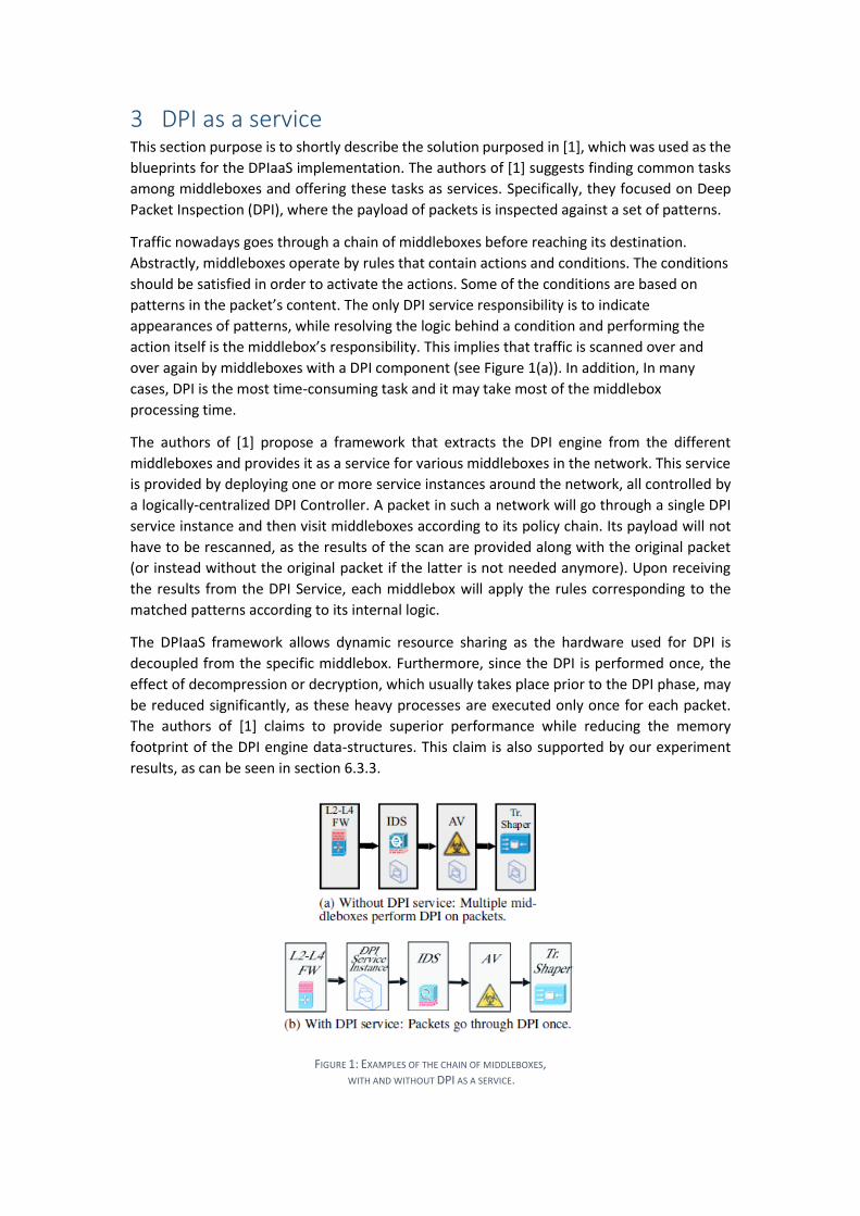
over again by middleboxes with a DPI component (see Figure 1(a)). In addition, In many
cases, DPI is the most time-consuming task and it may take most of the middlebox
processing time.
The authors of [1] propose a framework that extracts the DPI engine from the different
middleboxes and provides it as a service for various middleboxes in the network. This service
is provided by deploying one or more service instances around the network, all controlled by
a logically-centralized DPI Controller. A packet in such a network will go through a single DPI
service instance and then visit middleboxes according to its policy chain. Its payload will not
have to be rescanned, as the results of the scan are provided along with the original packet
(or instead without the original packet if the latter is not needed anymore). Upon receiving
the results from the DPI Service, each middlebox will apply the rules corresponding to the
matched patterns according to its internal logic.
The DPIaaS framework allows dynamic resource sharing as the hardware used for DPI is
decoupled from the specific middlebox. Furthermore, since the DPI is performed once, the
effect of decompression or decryption, which usually takes place prior to the DPI phase, may
be reduced significantly, as these heavy processes are executed only once for each packet.
The authors of [1] claims to provide superior performance while reducing the memory
footprint of the DPI engine data-structures. This claim is also supported by our experiment
results, as can be seen in section 6.3.3.
FIGURE 1: EXAMPLES OF THE CHAIN OF MIDDLEBOXES, WITH AND WITHOUT DPI AS A SERVICE.
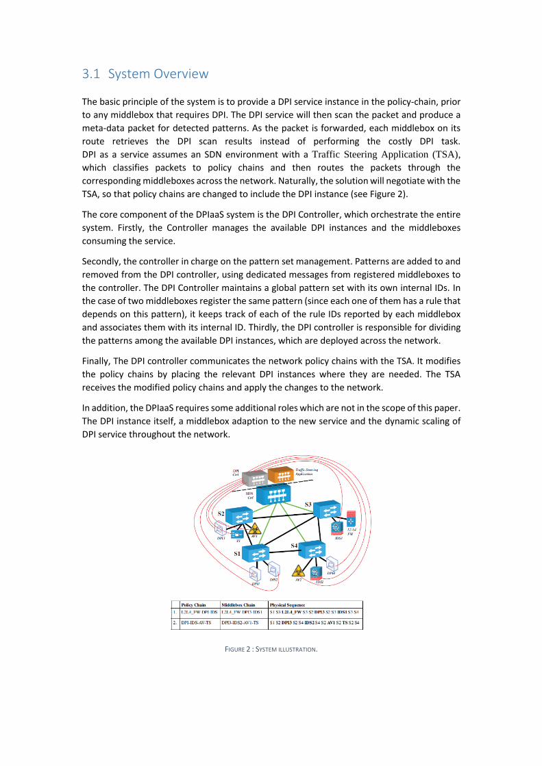
3.1 System Overview
The basic principle of the system is to provide a DPI service instance in the policy-chain, prior
to any middlebox that requires DPI. The DPI service will then scan the packet and produce a
meta-data packet for detected patterns. As the packet is forwarded, each middlebox on its
route retrieves the DPI scan results instead of performing the costly DPI task.
DPI as a service assumes an SDN environment with a Traffic Steering Application (TSA),
which classifies packets to policy chains and then routes the packets through the
corresponding middleboxes across the network. Naturally, the solution will negotiate with the
TSA, so that policy chains are changed to include the DPI instance (see Figure 2). The core component of the DPIaaS system is the DPI Controller, which orchestrate the entire
system. Firstly, the Controller manages the available DPI instances and the middleboxes
consuming the service.
Secondly, the controller in charge on the pattern set management. Patterns are added to and
removed from the DPI controller, using dedicated messages from registered middleboxes to
the controller. The DPI Controller maintains a global pattern set with its own internal IDs. In
the case of two middleboxes register the same pattern (since each one of them has a rule that
depends on this pattern), it keeps track of each of the rule IDs reported by each middlebox
and associates them with its internal ID. Thirdly, the DPI controller is responsible for dividing
the patterns among the available DPI instances, which are deployed across the network.
Finally, The DPI controller communicates the network policy chains with the TSA. It modifies
the policy chains by placing the relevant DPI instances where they are needed. The TSA
receives the modified policy chains and apply the changes to the network.
In addition, the DPIaaS requires some additional roles which are not in the scope of this paper.
The DPI instance itself, a middlebox adaption to the new service and the dynamic scaling of
DPI service throughout the network.
FIGURE 2 : SYSTEM ILLUSTRATION.
4 Traffic Steering Application (TSA)
Network policies typically require packets to go through a sequence of middleboxes (e.g.,
firewall+IDS+proxy). However, enforcing such policy is highly complex in a regular network.
This complexity stems from the need to carefully plan the network topology, manually set
up rules to route traffic through the desired sequence of middleboxes and implement
safeguards for correct operation in the presence of failures and overload.
Software-Defined Networking (SDN) offers a promising alternative for middlebox policy
enforcement. By using logically centralized management, decoupling the data and control
planes and providing the ability to programmatically configure forwarding rules. SDN can
eliminate the need to manually plan middlebox placements or configure routes to enforce
such policies. [2]
In our work we implemented a simple TSA, which provides the enforcement of an arbitrary
middlebox chains. For simplicity's sake, we did not handle some complex implications which
may arise when implementing TSA, among others: the TCAM resources limitations, packet
modifications by the middlebox and load-balancing part of the chain. Thus, our TSA should
simply be able to traverse packets in a policy group through a defined set of middlebox.
The following guidelines of implementing such TSA were taken from the paper “SIMPLE-fying
middlebox policy enforcement using SDN” [2].
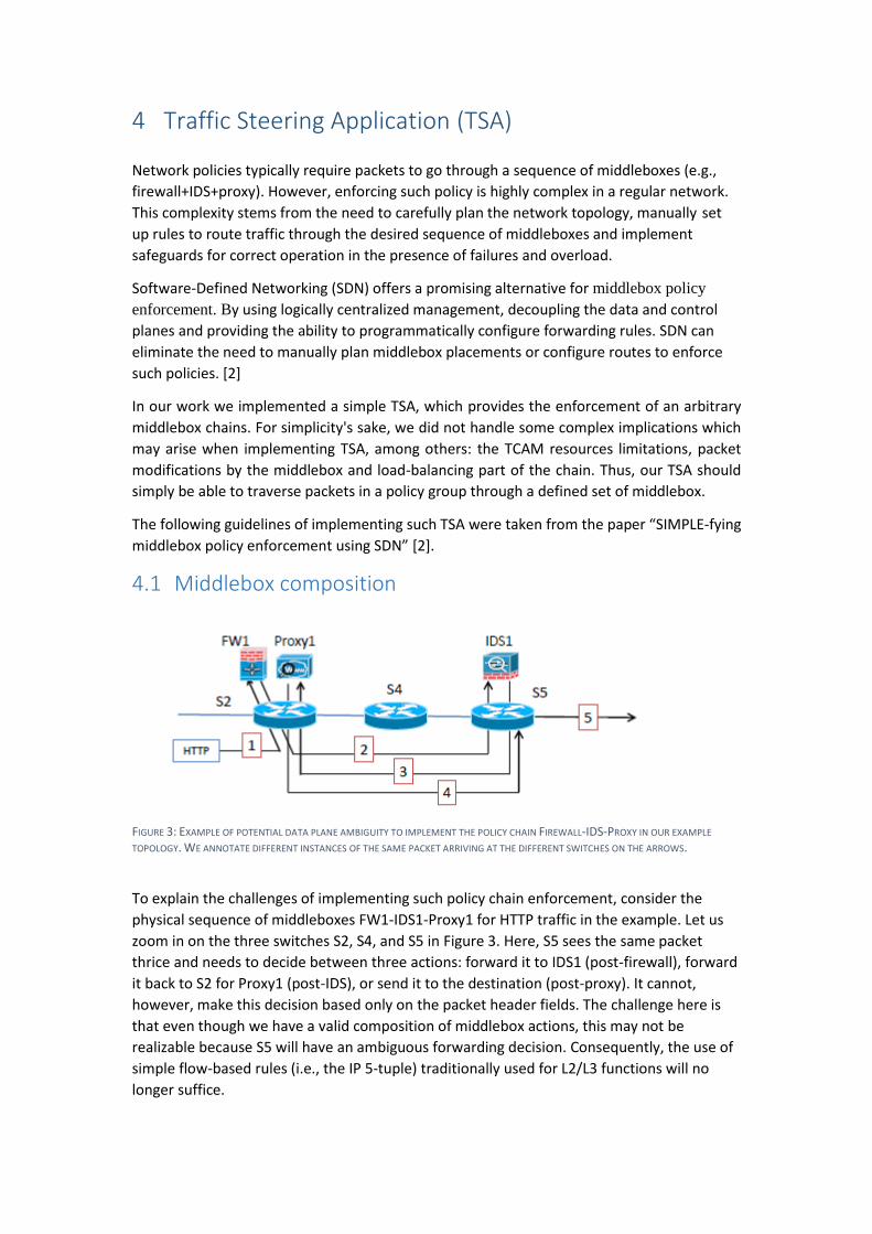
4.1 Middlebox composition
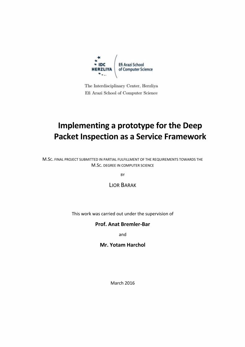
FIGURE 3: EXAMPLE OF POTENTIAL DATA PLANE AMBIGUITY TO IMPLEMENT THE POLICY CHAIN FIREWALL-IDS-PROXY IN OUR EXAMPLE
TOPOLOGY. WE ANNOTATE DIFFERENT INSTANCES OF THE SAME PACKET ARRIVING AT THE DIFFERENT SWITCHES ON THE ARROWS.
To explain the challenges of implementing such policy chain enforcement, consider the
physical sequence of middleboxes FW1-IDS1-Proxy1 for HTTP traffic in the example. Let us
zoom in on the three switches S2, S4, and S5 in Figure 3. Here, S5 sees the same packet
thrice and needs to decide between three actions: forward it to IDS1 (post-firewall), forward
it back to S2 for Proxy1 (post-IDS), or send it to the destination (post-proxy). It cannot,
however, make this decision based only on the packet header fields. The challenge here is
that even though we have a valid composition of middlebox actions, this may not be
realizable because S5 will have an ambiguous forwarding decision. Consequently, the use of
simple flow-based rules (i.e., the IP 5-tuple) traditionally used for L2/L3 functions will no
longer suffice.
To address these problems, we present a data plane solution that uses a combination of tags
and tunnels. While the use of tagging or tunneling in a general networking or SDN context is
not new, our specific contribution here is in using these ideas in the context of middlebox
policy enforcement.
Referring back to the Figure 3, for S5 to know the next hop, it needs to know if a packet has
traversed the Firewall (send to IDS), or has traversed both Firewall and IDS (send to S2), or has
traversed all three middleboxes (send to destination). That is, we need switches to identify
the segment in the middlebox processing chain that the packet is currently in. A segment is a
sequence of switches starting at a middlebox (or an ingress gateway) and terminating at the
next middlebox in the logical chain. Intuitively, we can track the segment by keeping “per
packet state” in the controller or in the switch. As neither option is practical, we’ve used a
combination of topological context and packet tagging to encode this processing state.
If the sequence of switches is loop free, i.e. each directional link appears at most once in the
sequence. In this case, a switch can use the incoming interface to identify the logical segment.
Consider the sequence FW1-IDS1 in FIGURE 3, where the packet needs to traverse In–S2-FW1-
S2-S4-S5-IDS1-S5–Out. In this case, S2 forwards packets arriving on “In” to FW1 and packets
arriving on the FW1 port to S4. If there is a loop in the physical sequence, then the
combination of input interface and packet header fields cannot identify the middlebox
segment. To address this, we introduce a ProcState tag that encodes the packet’s processing
state; ProcState tags are embedded inside the packet header using either VLAN tags, MPLS
labels, or unused fields in the IP header, depending on the fields supported in the SDN
switches. The controller installs the tag addition rules at the first switch of each segment,
based on packet header fields and the input port. Then, downstream switches use these tags
for their forwarding decision.
If we go back to Figure 3, we need tag addition rules at S2: {HTTP, from FW1} ProcState
=FW; {HTTP, from Proxy1}ProcState =Proxy. The forwarding rules at S5 are: {HTTP,
ProcState =FW} forward to IDS1; and {HTTP, ProcState =Proxy}forward to destination.
The key concept here is, that S5 can use the ProcState tags to differentiate between the first
instance of the packet arriving in the second segment (send to IDS) and the fourth segment
(send to destination).
In my implementation I considered the more complex scenario and used a ProcState tag.
5 Implementation
This section will describe the implementation details of the DPI as a service concept described
in the paper. We aimed to implement a simple, full functioning system, which will be a proof
of concept to the DPIaaS theory and to the extraction of other functions to network services.
Therefore, we focused on the essential subsets of features on the DPI-server and TSA, which
are necessary for a full functioning DPIaaS network.
Note, that the Middleboxes and DPI instances where not part of the implementation scope,
and the same tools were used here as those were used in the original paper, with minor
modifications that will be elaborated in section 6.1 Tools.
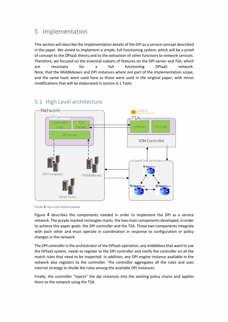
5.1 High Level architecture
FIGURE 4: HIGH LEVEL DESIGN DIAGRAM
Figure 4 describes the components needed in order to implement the DPI as a service
network. The purple marked rectangles marks the two main components developed, in order
to achieve this paper goals: the DPI controller and the TSA. Those two components integrate
with each other and must operate in coordination in response to configuration or policy
changes in the network.
The DPI controller is the orchestrator of the DPIaaS operation, any middlebox that want to use
the DPIaaS system, needs to register to the DPI controller and notify the controller on all the
match rules that need to be inspected. In addition, any DPI engine instance available in the
network also registers to the controller. The controller aggregates all the rules and uses
internal strategy to divide the rules among the available DPI instances.
Finally, the controller “injects” the dpi instances into the existing policy chains and applies
them to the network using the TSA.
The TSA rule is to apply the existing (and changing) policy chains on the network.
It uses an underlying SDN controller(OpenDayLight) by setting the necessary rules into the OF
switches. These rules will make each packet to traverse through the corresponding dpi
instances and middlebox, according to the policy chain. The packet then will be released to
the underling network routing toward its destination.
Regarding connectivity, the DPI controller, Middleboxes and DPI-Instances, operate and
communicate using the data-plane network, while the TSA through the SDN controller uses
the control plane network to configure the rules. However, the connectivity between the TSA
and the DPI controller, which is mandatory for the DPIaaS operation, suggests a special
approach as they belong to different planes. The solution was to connect them directly, by
using a dedicated link and not to break the planes abstraction.
5.2 The DPI controller
The DPI controller is the main component in the DPIaaS. The controller must communicate
with all the middleboxes which are using the DPI-service, all the DPI instances existing in the
network and all the rules needs to be inspected. Its internal logic decides how to divide the
rules between the dpi instances, and where to place each instance in the policy chain.
The DPI controller keeps an open channel with the middleboxes, Instances and TSA in order
to notify and get notified on any policy or configuration change in the network.
To simplify the controller we’ve assumed that the DPI instances are not automatically
deployed by the DPI-server but are created manually.
5.2.1 Requirements
In order to play the DPI controller rule successfully, the following main features needs to be
implemented.
5.2.1.1 Act as a server for middleboxes and instances
As mentioned before, the DPI controller needs to communicate with every component in the
DPI network. The DPI controller listens for incoming messages from middleboxes and
instances, register new connections, holds an open connection and communicates with them
using the DPIaaS protocol. The DPI controller also needs to be aware for disconnections and
to react accordingly.
5.2.1.2 Global Match-Rules Set
One of the advantages of centralize DPI service is the ability to aggregate identical rules from
different middleboxes, and inspect each packet against this set of rules only once.
In order to achieve this, the DPI controller assign an internal rule id for every rule assigned by
a middlebox in such way, that identical rules get the same internal id. Even if multiple
middlebox register with the same match rule, only one rule will be assign to a DPI instance.
This implies that the DPI instance must know only the internal id.
The DPI controller achieves that by holding an internal match rules mapping between the
middleboxes rules to an internal rule. And keeps track on each internal rule as the
middleboxes connect and disconnect from the controller. The rules then, added and removed
throughout the controller life-time. The DPI controller must link every internal rule to all of its
connected middleboxes, and take it into consideration when dividing the rules between
instances and placing instances in the policy chains in order the ensure every middlebox will
get the relevant matches.
5.2.1.3 Managing DPI instances
The DPI controller holds a set of all the available DPI instances in the network and a mapping
of each instance and the internal rules assigned to each one. The DPI controller can assign
match rules to the instances and react to changes in their availability.
5.2.1.4 Dividing Match-Rules to instances
One of the most important pieces of logic in the DPI controller is how to divide the match rules
among the different instances. A few issues can come in to consideration when implementing
such an algorithm:
The match patterns, when knowing the internal implementation of the DPI instances
patterns can divide using the strings to optimize the algorithm using for DPI.
The mapping between middleboxes and their rules, can affect the structure of the
network created the TSA in order to apply the DPIaaS and therefore its efficiency.
The mapping between DPI instances and current assigned rules, one would probably
want to utilize the available instances and load-balance their resources.
One would probably will want to minimize or limit the number of chain changes in the
network in order to keep it stable. Frequent routing changes can affect the efficiency
of the network.
Derived from the above, the division of the rules needs to be examined in almost every
configuration change: addition or removal of middlebox, instance or match rule and changes
in policy chains.
Finding the optimal strategy is a complex mission involving examination of all the previous
considerations, designing some algorithm and testing them in various environments and
situations. In this work scope I decided to focus on creating a whole working system, and not
to optimize its rules division. But as will be explained in section 5.2.2 , the Dpi controller
design lays the foundation for this optimization.
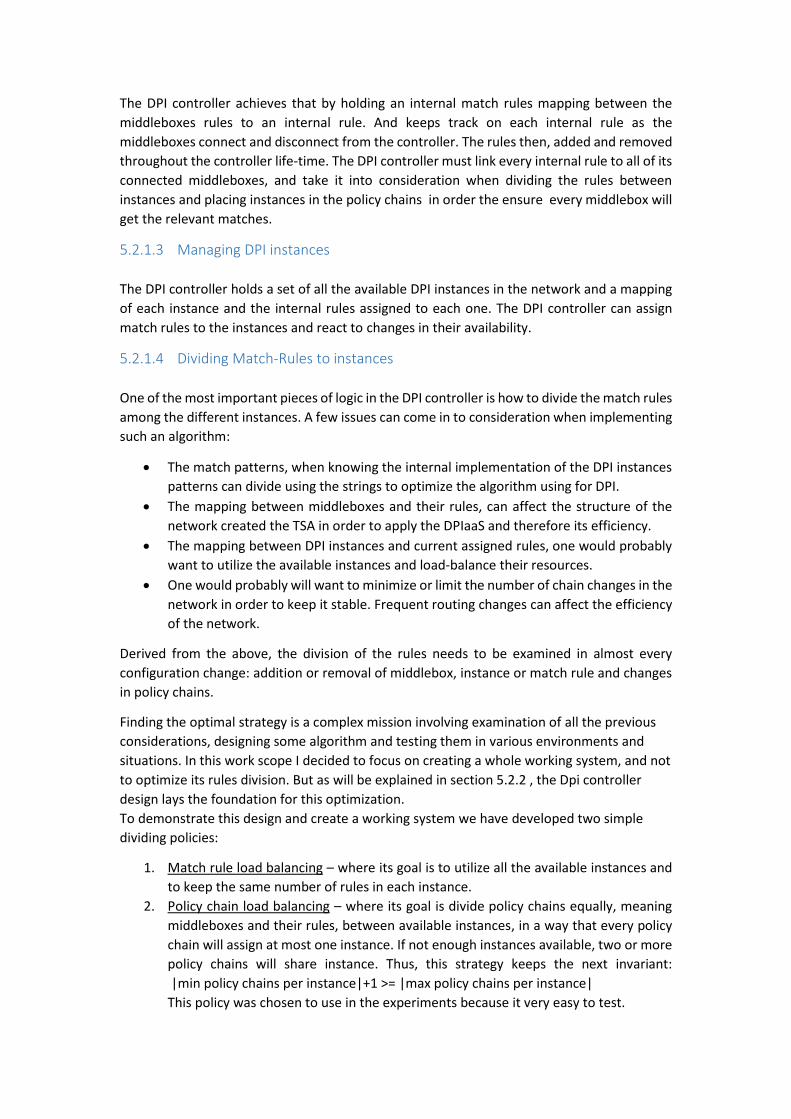
To demonstrate this design and create a working system we have developed two simple
dividing policies:
1. Match rule load balancing – where its goal is to utilize all the available instances and
to keep the same number of rules in each instance.
2. Policy chain load balancing – where its goal is divide policy chains equally, meaning
middleboxes and their rules, between available instances, in a way that every policy
chain will assign at most one instance. If not enough instances available, two or more
policy chains will share instance. Thus, this strategy keeps the next invariant:
|min policy chains per instance|+1 >= |max policy chains per instance|
This policy was chosen to use in the experiments because it very easy to test.
5.2.1.5 Generate the corresponding policy chain
Once the rules are divided between the instances, the DPI controller needs to place each dpi
instance in the right place across the policy chains. Even though this task is simpler than the
previous, the main consideration is that every instance should precede any middlebox that
requires its rules. In order to achieve that, the DPI controller needs to use its knowledge about
middlebox-rules and instances-rules mapping and the policy chains themselves.
For the purposes of this work, I have implemented a simple strategy that uses the "policy chain
load balancing" and simply retrieves from that strategy for each policy the instance assign to
it, and place the instance in the begging of the chain.
5.2.1.6 Pulling and pushing Policy chains
For both the "build new policy chain" and "dividing match-rules" requirements, the
controller needs to be able to pull and push the policy chain to the TSA application .
5.2.1.7 Reacting to changes in the DPI network/TSA
The DPI controller not only operates on network setup, it needs to get notified on changes in
the network – middleboxes/instance go up/down, rules added/deleted or policy chains
changes.
When any such event occurs, the DPI controller reacts immediately and according to the
previous requirements.
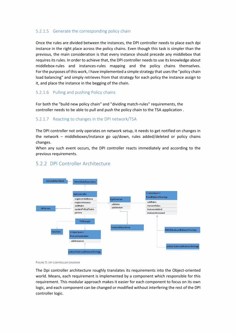
5.2.2 DPI Controller Architecture
FIGURE 5: DPI CONTROLLER DIAGRAM
The Dpi controller architecture roughly translates its requirements into the Object-oriented
world. Means, each requirement is implemented by a component which responsible for this
requirement. This modular approach makes it easier for each component to focus on its own
logic, and each component can be changed or modified without interfering the rest of the DPI
controller logic.
In addition we took into consideration that the match-rules diving logic and the policy chain
composition are most likely going to change frequently, and probably a real deployment of
this service will hold multiple options to choose from depending on the network configuration.
This is handled by using the strategy design pattern which enable adding new logic by simply
implementing an interface with few simple methods.
DPI Controller class
This class is the core and Coordinator of the application, its rule is to react to changes in the
DPI network notified by its satellite components. It is then applies the needed logic and
operations, again using the relevant components for task in the right order.
5.2.2.1 DPIServer
The DPIServer communicates in the network level with all the DPI instances and middlebox,
it passes changes in the DPI network to the DPI controller and applies the match rules to the
DPI instances. The DPIServer uses the DPIaaS protocol, described in appendix 8.3.2, to perform
its rule.
5.2.2.2 MatchRuleRepository
This repository keeps track on the mapping between middleboxes and its match-rules, and
from match-rules with identical pattern to a single internal match-rule.
The rest of the system uses only the internal matchRule and uses the repository to find for
each middlebox its internals rule and vice versa. The repository needs to keep this mapping
valid as rules and matchboxes added or removed throughout the lifetime of the application.
5.2.2.3 DPIForeman
As its name applied the foreman rule is to assign jobs (or internal match-rules) to the available
DPI instances. In order to achieve this, it uses the InstanceRepository, which holds the
available instances and their current assigned jobs, and the LoadBalanceStrategy, which as
explained before can be implemented in many ways by the overriding the methods described
in the diagram.
In order to perform its rule, the LoadBalanceStrategy can access the InstanceRepository and
MatchRuleRepository, as any implementation would likely need to know current rules-
instance or rules-middleboxes mapping.
5.2.2.4 TSAFacade
The TSAFacade rule is to encapsulate all the DPIController requirements regarding the TSA,
it communicates with the TSA - notifies the controller on the policy chain changes and updated
the TSA on chains modifications done by the service.
As part of its rule the façade also constructs the policy chains themselves, when change is
made to match-rules assignments, the façade uses the PolicyChainBuilder strategy, to modify
current policy chain when needed. In a similar manner to the LoadBalanceStrategy strategy,
this strategy can and probably uses the middlebox/instance-match Rules mapping in order to
construct the new policy chains.

However, the chosen strategy implementation, as described in the section 5.2.1.5, is much
simpler. It uses the fact that the implemented policyChainLoadBalance strategy already
assigned an instance per chain. Thus, the builder implementation just needs to concat the
assigned instance in the begging of the corresponding chain.
5.3 TSA Implementation
The TSA was implemented using OpenDayLight controller – AD-SAL version, and the
OpenFlow13 protocol. We have used the vlan-id field for the “ProcState” tagging as described
in section4.1 (Middlebox composition).
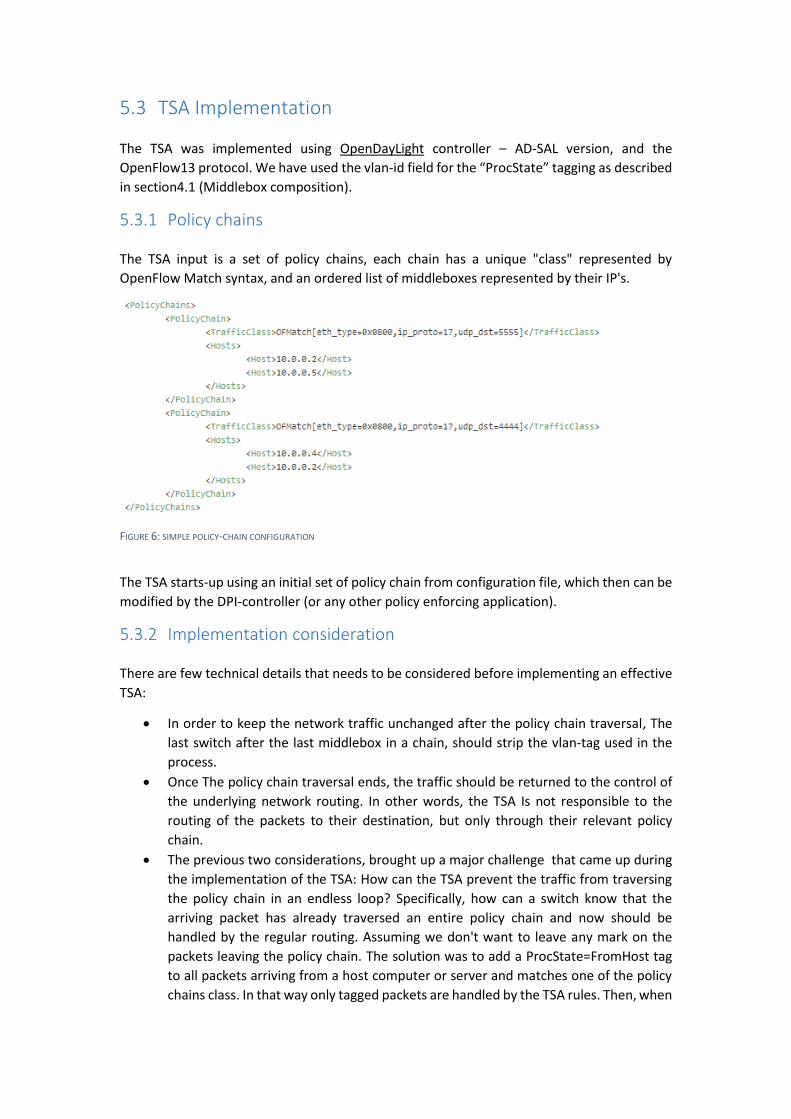
5.3.1 Policy chains
The TSA input is a set of policy chains, each chain has a unique "class" represented by
OpenFlow Match syntax, and an ordered list of middleboxes represented by their IP's.
FIGURE 6: SIMPLE POLICY-CHAIN CONFIGURATION
The TSA starts-up using an initial set of policy chain from configuration file, which then can be
modified by the DPI-controller (or any other policy enforcing application).
5.3.2 Implementation consideration
There are few technical details that needs to be considered before implementing an effective
TSA:
In order to keep the network traffic unchanged after the policy chain traversal, The
last switch after the last middlebox in a chain, should strip the vlan-tag used in the
process.
Once The policy chain traversal ends, the traffic should be returned to the control of
the underlying network routing. In other words, the TSA Is not responsible to the
routing of the packets to their destination, but only through their relevant policy
chain.
The previous two considerations, brought up a major challenge that came up during
the implementation of the TSA: How can the TSA prevent the traffic from traversing
the policy chain in an endless loop? Specifically, how can a switch know that the
arriving packet has already traversed an entire policy chain and now should be
handled by the regular routing. Assuming we don't want to leave any mark on the
packets leaving the policy chain. The solution was to add a ProcState=FromHost tag
to all packets arriving from a host computer or server and matches one of the policy
chains class. In that way only tagged packets are handled by the TSA rules. Then, when
the packet leaves the last middlebox the tag is stripped, and the next switch gets a
“tagless” packet coming from a switch and not a host, and therefore don't apply any
TSA flows on it.
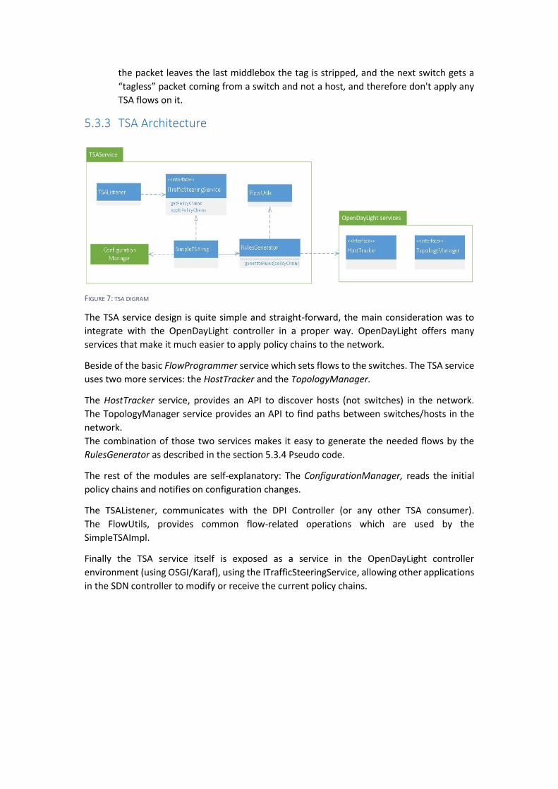
5.3.3 TSA Architecture
FIGURE 7: TSA DIGRAM
The TSA service design is quite simple and straight-forward, the main consideration was to
integrate with the OpenDayLight controller in a proper way. OpenDayLight offers many
services that make it much easier to apply policy chains to the network.
Beside of the basic FlowProgrammer service which sets flows to the switches. The TSA service
uses two more services: the HostTracker and the TopologyManager.
The HostTracker service, provides an API to discover hosts (not switches) in the network.
The TopologyManager service provides an API to find paths between switches/hosts in the
network.
The combination of those two services makes it easy to generate the needed flows by the
RulesGenerator as described in the section 5.3.4 Pseudo code.
The rest of the modules are self-explanatory: The ConfigurationManager, reads the initial
policy chains and notifies on configuration changes.
The TSAListener, communicates with the DPI Controller (or any other TSA consumer).
The FlowUtils, provides common flow-related operations which are used by the
SimpleTSAImpl.
Finally the TSA service itself is exposed as a service in the OpenDayLight controller
environment (using OSGI/Karaf), using the ITrafficSteeringService, allowing other applications
in the SDN controller to modify or receive the current policy chains.
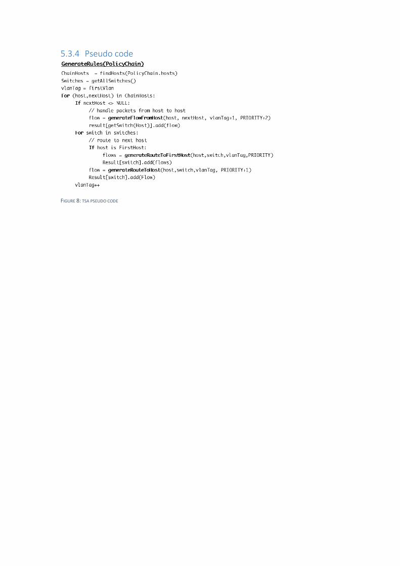
5.3.4 Pseudo code
FIGURE 8: TSA PSEUDO CODE
6 DPIaaS Evaluation
In this chapter we'll describe the process of deploying and testing the applications described
in the previous chapters. The TSA and DPI-Controller applications was tested in two different
environments:
Virtual, using Mininet simulated switches and hosts. And physical (or semi-virtual), using a real
OpenFlow switch and virtual machines distributed on real servers.
The virtual environment was mainly established for development purposes, and used for
functional testing and demonstrating the working functionality of the DPIaaS on various
complicated network scenarios. While the physical environment experiments aim to
demonstrate a working DPIaaS in more realistic scenario, with a real switch and hosts routing.
Therefore, the performance experiments, aimed to prove the original paper claim on
performance improvements using DPIaaS instead of regular network configuration, was
performed in the physical environment.
6.1 Tools
In both environments, in order to achieve a "live" underling network for the tested application
to run on, additional tools was developed. Those tools are essential for running the DPIaaS
and enabled us to test the application in complex situations.
6.1.1 Mocks
In the development phase in order to test the application, we needed mocks to mimic a
working network devices required for basic operation: a middlebox and a dpi instance.
Those mocks basically implementing the DPIaaS protocol described in section Error!
Reference source not found. , and send incoming packets back to the network in order to
keep the traffic flow.
Middlebox mock – The middlebox mock can be loaded with initial set of rules from an input
file, then it registers and negotiates the rules with the DPI-controller. In addition the mock
supports adding and removing rules dynamically using shell commands.
Finally, the mock can print any arriving message which allow us to test the TSA, and verify that
messages corresponding to the relevant policy chain actually arriving to middlebox.
DPI instance mock – The DPI instance mock is much simpler and basically just prints any
incoming message to the console. This simple operation allow us to verify that the expected
rules was assign to every DPI instance, and as in the middlebox mock that the TSA is working
correctly.
6.1.2 Wrappers
For more realistic experiments, and especially for the performance experiments, we needed
middleboxes and DPI-instances that actually perform their rules. Meaning, a DPI-instance
that runs DPI on incoming messages using its assigned rules and generates match
notification packets. And a simple middlebox that can wait to those incoming match
notification, and pairs them to the examined packets.
In order to achieve this, we have used the same executables used for evaluating in the
original paper [1], which perform those exact operations. The code of the executables is
available at https://github.com/DeepnessLab/moly.
However, in order to use those tools in a working DPIaaS environment we needed to "wrap"
them in thin layer that provides a few major functions:
Communicates using the DPIaaS protocol
Saves the actual DPI-instance state – assigned rules
Allows us to interact with the middlebox – add/remove rules
Translates any change of state to a working execution of the underlying tool.
Note that in this implementation, every change in the DPI-instance or middlebox state causes
the underlying executable to restart. Which makes those wrappers far from ideal to test an
environment with ever changing configurations. Never the less, for our purposes they are
suffice. This is because our usage is to set up a configuration and then to measure several
performance matrixes.
6.1.3 Mininet network generation script
In the virtual environment, several actions need to be taken in order the setup a functioning
DPIaaS network. Those steps, which will be described next, was implemented using a script
which saves time and prevents errors:
1. Running the Mininet network with the desired topology
generating a fat-tree topology using input arguments and start-up Mininet with this
topology, and a OF13 switch configuration. The script can easily be extended to support
more topologies.
2. Ping all host pairs to create connectivity
in order to create the “regular routing" flows, messages need to be sent between all the
hosts in the network. This step also validate the success of the previous step.
3. Connecting the DPI controller Host to the SDN controller
In a DPIaaS network the DPI-Controller is a special case, in which it has one “leg” in the
"regular network" and the other in the SDN network. This configuration can be achieved
in a physical network by simply connecting cables, but needs special consideration in
order to be deployed in Mininet. The script connect the DPI-controller host to the SDN
controller.
4. Running DPI-network parts on desired hosts
Once the DPIaaS network is up a running, one can save time by specifying, using command
arguments, on which hosts he wants to setup middleboxes and/or DPI instances.
The script starts up the DPI controller and then the middleboxes and instances.
Furthermore, the user can specify initial set of rules for some middlebox if he wants to.
5. Can automatically start sniffing on the network parts
Finally, the user can inform the script that he wants open sniffing terminals on the hosts
with running middleboxes/instances. Which helps to perform tests on the network.
For example, look at the following script execution:
python dpiNet.py --topo 4,6,2 --middlebox h2=rules/rules1.json h4=rules/rules2.json
h5=rules/rules3.json --instance h7 –xterms
This will set up a running Mininet network, with fat-tree topology, using the 4,6,2 arguments:
3 middleboxes h2,h4 and h5 each with its initial sets of rules and one DPI-instance h7. After
the network will set up the script will open terminals for all the DPI-network elements.
Because no DPI-controller was explicitly chosen, the DPI-controller will be deployed by default
on the host h1. Note that the precondition for executing this script is a running SDN controller
with TSA on the local server.
6.2 Functional Evaluation
The functional evaluation of the system was conducted in a full virtual environment, using
Mininet. Using Mininet to simulate the network allow us to test our application in a large and
complex networks, which would have been very hard and time consuming to configure using
physical or virtual machines.
We used Mininet and additional tools, which will be described next, to create a working
demonstration of the DPIaaS concept using the implemented applications: the DPI-Controller
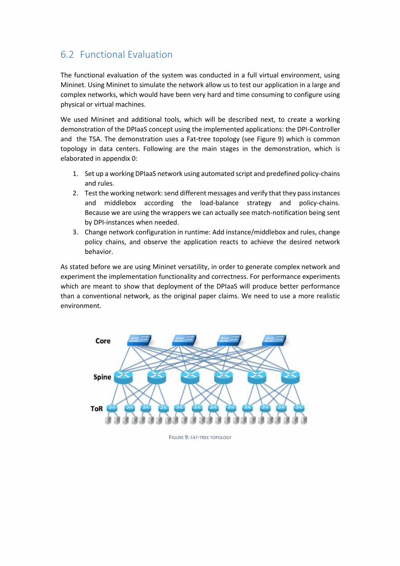
and the TSA. The demonstration uses a Fat-tree topology (see Figure 9) which is common
topology in data centers. Following are the main stages in the demonstration, which is
elaborated in appendix 0:
1. Set up a working DPIaaS network using automated script and predefined policy-chains
and rules.
2. Test the working network: send different messages and verify that they pass instances
and middlebox according the load-balance strategy and policy-chains.
Because we are using the wrappers we can actually see match-notification being sent
by DPI-instances when needed.
3. Change network configuration in runtime: Add instance/middlebox and rules, change
policy chains, and observe the application reacts to achieve the desired network
behavior.
As stated before we are using Mininet versatility, in order to generate complex network and
experiment the implementation functionality and correctness. For performance experiments
which are meant to show that deployment of the DPIaaS will produce better performance
than a conventional network, as the original paper claims. We need to use a more realistic
environment.
FIGURE 9: FAT-TREE TOPOLOGY
6.3 Performance Evaluation
In order to demonstrate DPIaaS operation with physical OpenFlow switch, and in a realistic
data center environment as possible. we set up a configuration in the deepness lab using three
physical servers (Server1, Server2 and Server3), one OpenFlow switch and one regular
Ethernet switch. In addition to a regular management connection, each server has two
connections to the OF switch, one cooper 1G and one optical of 10G. In the experiment we
didn't use more than 1G bandwidth so we can address them as identical.
This environment was used to replicate the experiments that was conducted in the original
paper. Only now using a full functioning DPIaaS system, an high capacity switch and
broadband connections.
6.3.1 Experiments configuration
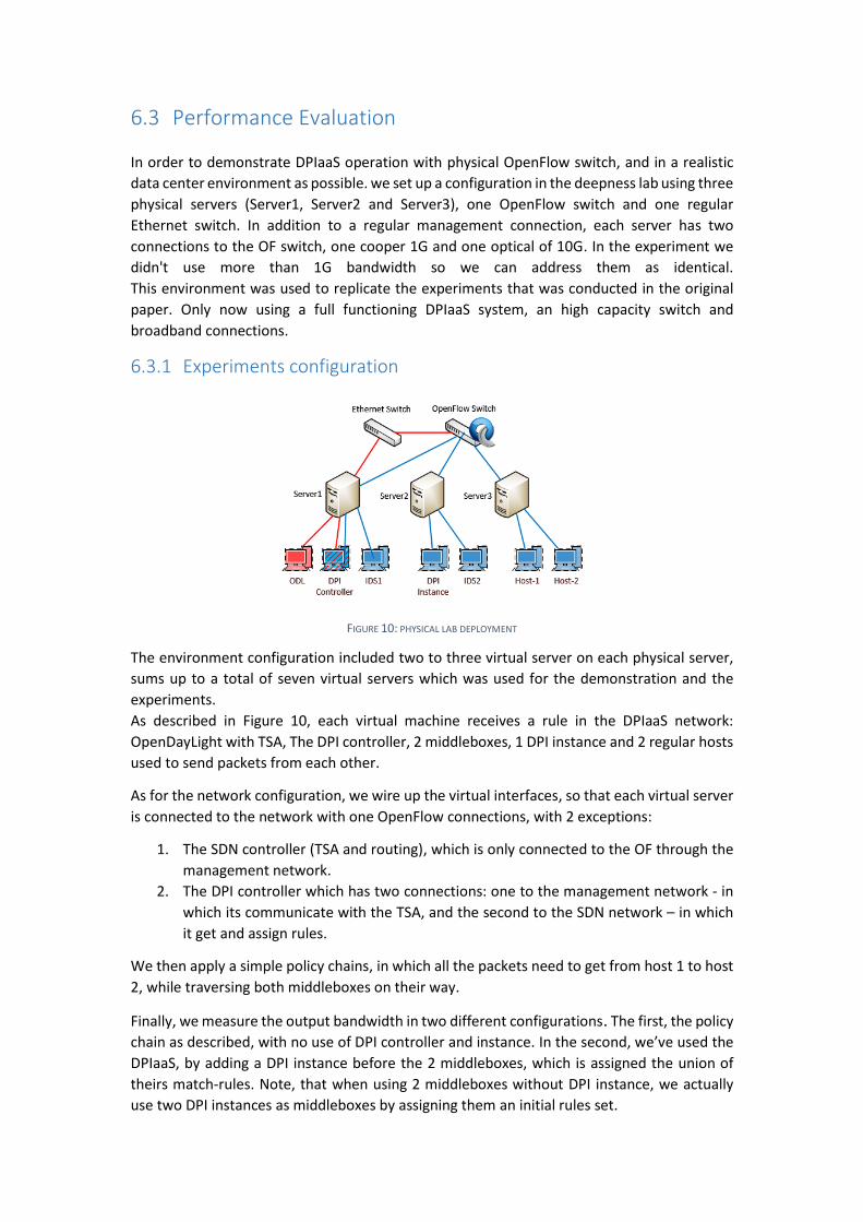
FIGURE 10: PHYSICAL LAB DEPLOYMENT
The environment configuration included two to three virtual server on each physical server,
sums up to a total of seven virtual servers which was used for the demonstration and the
experiments.
As described in Figure 10, each virtual machine receives a rule in the DPIaaS network:
OpenDayLight with TSA, The DPI controller, 2 middleboxes, 1 DPI instance and 2 regular hosts
used to send packets from each other.
As for the network configuration, we wire up the virtual interfaces, so that each virtual server
is connected to the network with one OpenFlow connections, with 2 exceptions:
1. The SDN controller (TSA and routing), which is only connected to the OF through the
management network.
2. The DPI controller which has two connections: one to the management network - in
which its communicate with the TSA, and the second to the SDN network – in which
it get and assign rules.
We then apply a simple policy chains, in which all the packets need to get from host 1 to host
2, while traversing both middleboxes on their way.
Finally, we measure the output bandwidth in two different configurations. The first, the policy
chain as described, with no use of DPI controller and instance. In the second, we’ve used the
DPIaaS, by adding a DPI instance before the 2 middleboxes, which is assigned the union of
theirs match-rules. Note, that when using 2 middleboxes without DPI instance, we actually
use two DPI instances as middleboxes by assigning them an initial rules set.
6.3.2 Data set
As in the original paper [1], we have used two different match-rules data sets in the
experiment.
The first, was the snort rules set, divided randomly between two middleboxes with a total of
~4500 rules. In the second, one middlebox used the snort rules and the other the ClamAV
rules, with a total of 9000 rules.
The experiments were conducted with an increasing number of rules to test the influence of
rules count on bandwidth in each scenario.
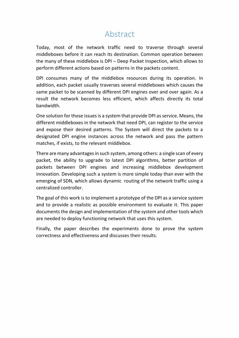
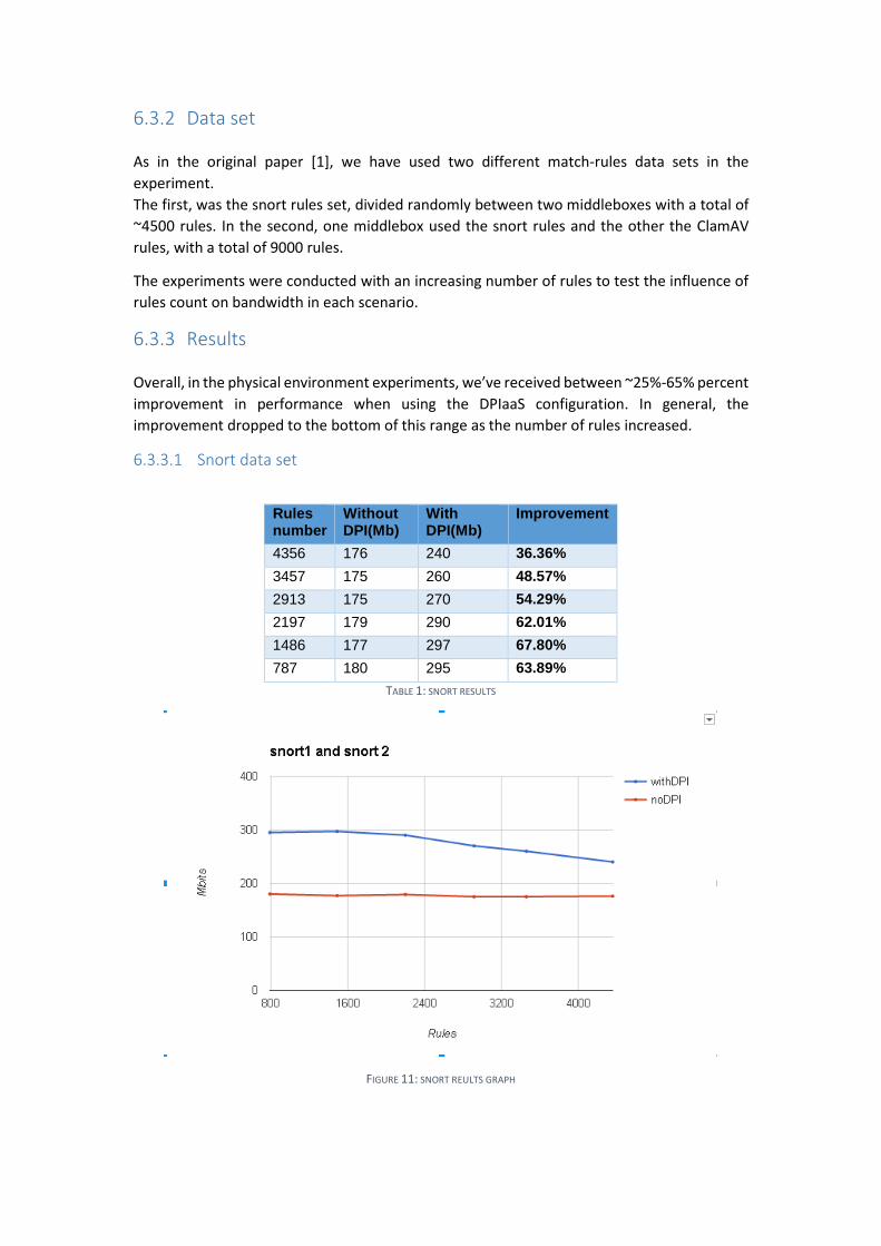
6.3.3 Results
Overall, in the physical environment experiments, we’ve received between ~25%-65% percent
improvement in performance when using the DPIaaS configuration. In general, the
improvement dropped to the bottom of this range as the number of rules increased.
6.3.3.1 Snort data set
Improvement With DPI(Mb)
Without DPI(Mb)
Rules number
36.36% 240 176 4356
48.57% 260 175 3457
54.29% 270 175 2913
62.01% 290 179 2197
67.80% 297 177 1486
63.89% 295 180 787
TABLE 1: SNORT RESULTS
FIGURE 11: SNORT REULTS GRAPH
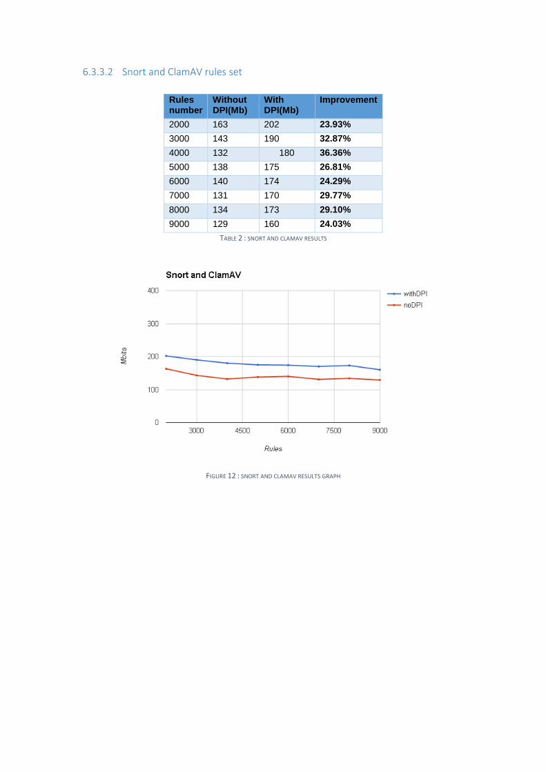
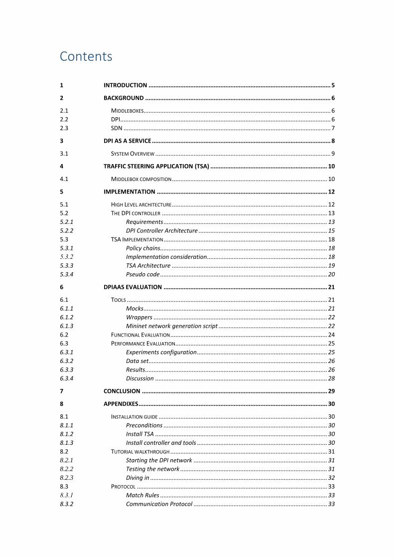
6.3.3.2 Snort and ClamAV rules set
Improvement With
DPI(Mb) Without DPI(Mb)
Rules number
23.93% 202 163 2000
32.87% 190 143 3000
36.36% 180 132 4000
26.81% 175 138 5000
24.29% 174 140 6000
29.77% 170 131 7000
29.10% 173 134 8000
24.03% 160 129 9000
TABLE 2 : SNORT AND CLAMAV RESULTS
FIGURE 12 : SNORT AND CLAMAV RESULTS GRAPH
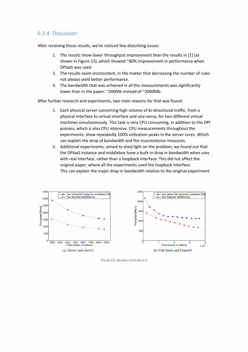
6.3.4 Discussion
After receiving those results, we’ve noticed few disturbing issues:
1. The results show lower throughput improvement than the results in [1] (as
shown in Figure 13), which showed ~80% improvement in performance when
DPIaaS was used.
2. The results seem inconsistent, in the matter that decreasing the number of rules
not always yield better performance.
3. The bandwidth that was achieved in all the measurements was significantly
lower than in the paper: ~200Mb instead of ~2000Mb.
After further research and experiments, two main reasons for that was found:
1. Each physical server converting high volume of bi-directional traffic, from a
physical interface to virtual interface and vice-versa, for two different virtual
machines simultaneously. This task is very CPU consuming, in addition to the DPI
process, which is also CPU intensive. CPU measurements throughout the
experiments, show repeatedly 100% utilization peaks in the server cores. Which
can explain the drop of bandwidth and the inconsistence measures.
2. Additional experiments, aimed to shed light on the problem, we found out that
the DPIaaS instance and middlebox have a built-in drop in bandwidth when uses
with real interface, rather than a loopback interface. This did not affect the
original paper, where all the experiments used the loopback interface.
This can explain the major drop in bandwidth relative to the original experiment.
FIGURE 13: ORIGINAL PAPER RESULTS
7 Conclusion
This work aimed to provide a proof of concept of theoretical idea presented in the paper
“Deep Packet Inspection as a Service”. Our implemented applications sums up to demonstrate
a full, although simple, working network, which uses DPI as scalable and dynamic service. It
has been shown that, as the original paper claims, the extraction of the DPI to shared instances
shows a significant improvement in bandwidth, despite the technical difficulties to achieve a
higher bandwidth in both scenarios.
Furthermore, one of the goals achieved by this work, was to identify and tackle new
implementation challenges in a real DPIaaS deployment, for example the TSA loop issue
addressed in 5.3.2 or the TSA-Controller relation discussed in 5.1.
Future work can be various optimizations in using the prototype DPIaaS framework which
provides a framework for easy implementation of more complex strategies. To mention few:
more efficient match-rules division among the DPI instances, dynamic scaling of DPI instances
across the network, supporting load-balancing of DPI-instances etc. Moreover, this framework
can even be expanded in order to provide services for other key network functions beside
Deep Packet Inspection.
8 Appendixes 8.1 Installation guide Instruction how to build the applications used in this paper, which are preconditions for
running the tutorial in appendix 0
The source code is available in the repository https://github.com/DeepnessLab/moly
TSA_dir is ctrl/dpictrl-odl/TSA
controller_dir is ctrl/dpictrl-odl/DPIController
8.1.1 Preconditions Maven 3.3.9 or above
java 1.7 or above
8.1.2 Install TSA
The TSA_dir holds the source code for the TSA plugin, a simple routing plugin and a Maven
build script for fetching and building OpenDayLight and the above plugins:
We’ll start with building it all (it’s going to take some time), run from TSA_dir:
mvn install
We now just need to copy the two plugins into the plugins directory:
cp dpi_tsa/target/dpi_tsa-0.5.1-SNAPSHOT.jar distribution/opendaylight-osgi-
adsal/target/distribution-osgi-adsal-1.1.0-SNAPSHOT-osgipackage/opendaylight/plugins/
cp adsal_L2_forwarding/target/adsal_L2_forwarding-0.5.0-SNAPSHOT.jar
distribution/opendaylight-osgi-adsal/target/distribution-osgi-adsal-1.1.0-SNAPSHOT-
osgipackage/opendaylight/plugins/
The TSA needs 2 config files to run, there are sample files I the TSA config dir:
cp dpi_tsa/config/*.* distribution/opendaylight-osgi-adsal/target/distribution-osgi-adsal-
1.1.0-SNAPSHOT-osgipackage/opendaylight/configuration/
8.1.3 Install controller and tools
Run from controller_dir:
mvn install
The controller, IDS wrapper and DPI instance wrapper are in the target directory
the Mininet network generation script is the scripts directory.
Now we are ready to run a simple tutorial as described in 8.2
8.2 Tutorial walkthrough 8.2.1 Starting the DPI network
1. Start ODL in a terminal tab or xterm:
xterm -e ~/ODL_RUN_LOCATION/run.sh -Xmx7G &
(make sure the tsa is not running)
the -Xmx is the ram allocated for the ODL.
2. Now we are ready to start our DPI Network, we will use the dpiNet.py script:
xterm -e sudo python dpiNet.py --topo 4,6,2 --middlebox h2=rules/rules1.json
h4=rules/rules2.json h5=rules/rules3.json --instance h7 --xterms
we will start the following DPI net:
a. the dpi-controller is on its default host (h1)
b. 3 middleboxes on h2, h4 and h5
c. each middlebox get its initial rules from the corresponding file (not
mandatory)
d. 1 dpi service instance on h7
e. open xterms on all previous host for sniffing
3. At first the mininet will be built and will be pinged for connectivity
(so far nothing special just regular mininet with forwarding)
4. When the “start TSA till 'waiting for controller..' and press any key..” message
appears we need to start the tsa, go to the ODL terminal:
a. type ss dpi to get the tsa bundle number
b. type start/refresh bundle_number
c. wait for 'waiting for controller..’
5. Press enter on the mininet wait for the mininet>
6. thats it the network is ready, we can see what is happening by looking at log.out file
8.2.2 Testing the network
1. We will start by opening 2 new xterms say h3 and h8. (xterm h3 h8)
2. Open on h8 ngrep (ngrep -t -d h8-eth0 -v ‘arp and lldp’)
3. Now we can play with netcat and see what happens to the network, but first lets
take a look at the tsa initial policy:
xterm -e nano ~/ODL_RUN_LOCATION/configuration/tsa_policy.xml &
4. We’ll start with a simple packet from h3 to h8,
on h3 type: echo liorbarak | nc -u 10.0.0.8 1234, and see the packet arrive on h8.
5. now lets use one of the tsa policy class ‘udp dst 4444’ -> echo liorbarak | nc -u
10.0.0.8 4444, now we should see thep packet arriving at h7 and then to the
corrseponding chain (h4->h2).
6. now we will use packet with pattern of one of the middleboxes lets say aaaaaaaaa
we should see the same scenario like at the previous step but now additional packet
arriving from h7 telling the middleboxes on the pattern match
7. finally we will do same thing with dest port 5555 , and see the tsa steer the packets
through h7 (the instance) and the first chain (h2->h5)
8.2.3 Diving in
In this part we are going to add an instance and a middlebox (and rules) to the network, and
make changes to the TSA:
1. Add another DPI service instance on h6:
mininet> xterm h6
on h6-xterm -> java -jar bin/serviceWrapper.jar -id h6 [--print-packets] (or just
ngrep)
now we can try again 5-7 from previous section and see how each chain gets a
different instance
2. now add another middlebox and make some changes on the tsa:
a. xterm on h20 and run -> java -jar bin/IDSWrapper.jar -id h20 --interactive [--
print-packets], and in the interactive console write add-rules 1,liorbarak
(at this point you can see that no change in network been made, previous
chapter will act the same)
b. on the tsa_policy.xml file we add the host <host>10.0.0.20</host> in the end
of the second chain, and change the policy class for example; dst port to
6666
c. like in 7. previous chapter. nothing special will happen. but if we use 6666
port we’ll see packets arrive at -> h7 h2 h5 h20 as intended with the match
packet following.
d. if we kill the middlebox on h20 we can see the report generated by the moly
MB
8.3 Protocol 8.3.1 Match Rules Each middlebox has a set of match rules that define the operation of either its own DPI
engine or the virtual DPI instance that performs the DPI process for it. A match rule specifies:
A pattern or a regular expression
Identification number (to be returned when this rule is matched and used by middlebox)
Optional: Start index, end index in L7 payload
Zero or more sets of header fields that a packet should match or not match in order to apply
for scanning against this rule (To be implemented in future).
A match rule is represented using JSON as follows:
{
className: 'MatchRule',
pattern: some exact-string or regular-expression string,
is_regex: true if pattern is a regular-expression or false otherwise,
rid: rule identification number,
}
8.3.2 Communication Protocol Messages in the system are encoded using JSON for the ease of its use. Fast-path data is
attached to packets and should be encoded more efficiently.
8.3.2.1 Middlebox to controller {
className: 'MiddleboxRegister',
id: middlebox unique ID,
name: middlebox name,
sibling id: sibling middlebox id,
flow flag: TRUE\FALSE,
stealth flag: TRUE\FALSE
}
{
className: 'MiddleboxRulesetAdd',
mid: middlebox unique ID,
rules: array of match rules as defined in Section 8.3.1
}
{
className: 'MiddleboxRulesetRemove',
mid: middlebox unique ID,
rules: array of match rule IDs (rid's)
}
{
className: 'MiddleboxDeregister',
id: middlebox unique ID
}
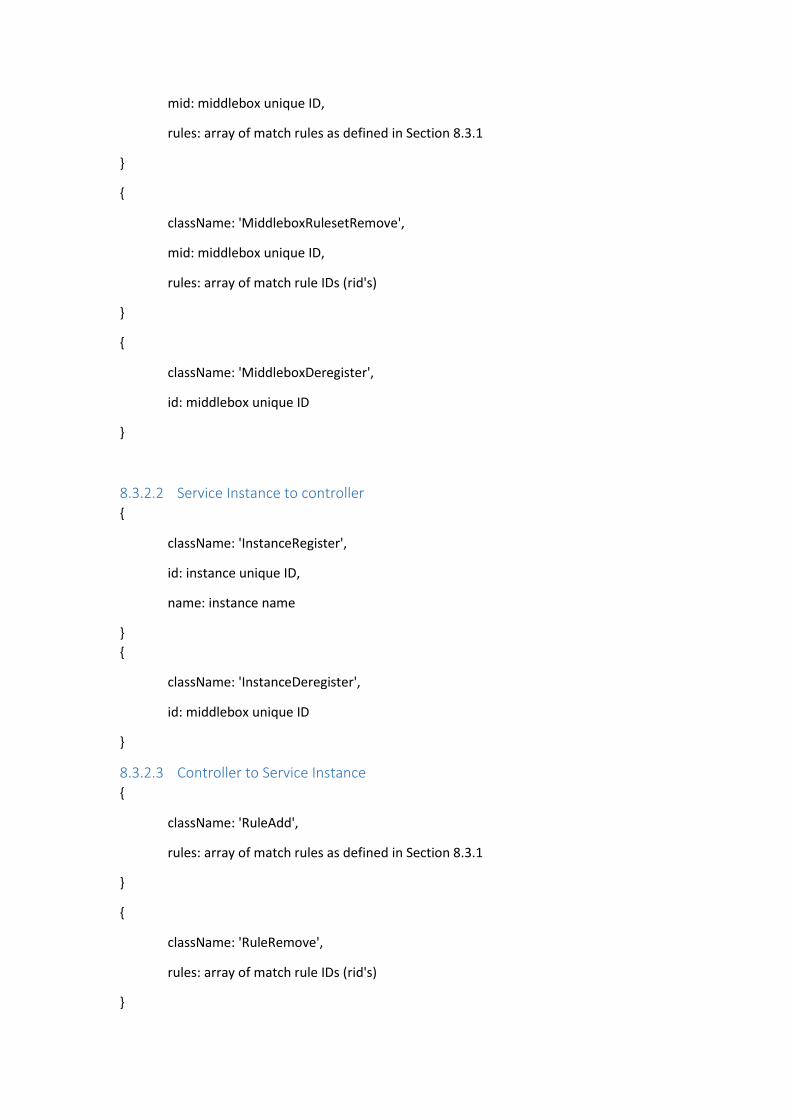
8.3.2.2 Service Instance to controller {
className: 'InstanceRegister',
id: instance unique ID,
name: instance name
}
{
className: 'InstanceDeregister',
id: middlebox unique ID
}
8.3.2.3 Controller to Service Instance {
className: 'RuleAdd',
rules: array of match rules as defined in Section 8.3.1
}
{
className: 'RuleRemove',
rules: array of match rule IDs (rid's)
}

References
[1] A. Bremler-Barr, Y. Harchol, D. Hay and Y. Koral, "Deep packet inspection as a service,"
in CoNEXT, 2014.
[2] Qazi, Z. Ayyub, C.-C. Tu, L. Chiang, R. Miao, V. Sekar and M. Yu, "SIMPLE-fying middlebox
policy enforcement using SDN," in SIGCOMM, 2013.

תקציר
לפני ( Middleboxes) דרך מספר רכיבי ביניים צריכה לעבורהרשת רוב תעבורת ם,כיו
DPI – Deep. פעולה משותפת לרוב המכריע של רכיבים אלו היא ההגעה ליעדה
packet inspection בגוף המצאות של תבניות, המאפשרת לבצע פעולות על פי
הפקטה.
DPI הצורכת את רוב משאבי הרכיב. ,היא פעולה יקרה מאוד מבחינת משאבים וזמן
בנוסף, מכיוון שאותן פקטות עוברות דרך מספר רכיבים כאלו, אותה פקטה נסרקת שוב
שונים. דבר זה גורם לבזבוז משאבים משמעותי ברמת הרשת DPIושוב על ידי מנועי
.הומשפיעה ישירות על רוחב הפס של
DPI as aכשירות של הרשת ) DPIהמציעה אחד הפתרונות לבעיה זו היא מערכת
Service כלומר, הרכיבים השונים ברשת הזקוקים לשירות .)DPI נרשמים לשירות ,
ומספקים לו את התבניות אותן הם מחפשים בפקטה. המערכת לאחר מכן מנתבת את
ומעבירה את ההתאמות המפוזרים ברכבי הרשת DPIהפקטות הרלוונטיות לרכיבי
שנמצאו, אם יש כאלו, לרכיב הרשום לשירות בצירוף הפקטה המתאימה.
היתרונות של מערכת כזו הם רבים, בין השאר: מעבר יחיד על כל פקטה ברשת, היכולת
, חלוקה אופטימלית DPIלהשתמש באלגוריתמים ובטכנולוגיה החדשה ביותר בתחום ה
אמצע המתאפשרת על -רת החדשנות בפיתוחי רכיביוהגב DPIשל תבניות בין מנועי ה
קל היום מערכת כזו . פיתוח DPIה בפיתוחידי התמקדות בלוגיקה הרכיב עצמו ולא
של תעבורת ריכוזי , המאפשרת ניתובSDNבעקבות התפתחות טכנלוגיית ה בהרבה
הרשת בצורה דינאמית.
מערכת כזו ולספק סביבה מציאותית ככל טיפוס של -מטרת עבודה זו היא לממש אב
עבודה זו מתעדת את תהליכי התכנון והפיתוח הניתן שתאפשר לבחון את המערכת.
של המערכת וכלים משלימים הדרושים להקמת רשת מתפקדת המשתמשת במערכת.
את נכונותה ואת הוכיחלבסוף, העבודה מתארת את הניסויים שנעשו על מנת ל
.תשל המערכהאפקטיביות
הרצליה הבינתחומי המרכז
ארזי אפי שם על המחשב למדעי הספר בית
מימוש אבטיפוס למערכת DPI as a service
המחשב במדעי מוסמך תואר לקראת מהדרישות חלק במילוי המוגש גמר פרויקט
ידי על
ברק ליאור
בהנחיית בוצעה זו עבודה בר-ברמלר ענת .פרופ
חול-הרמר. יותם
2016מרץ