Embed Size (px)
Citation preview
Implementing a MATLAB-based Self-Configurable Software Defined Radio Transceiver
Benjamin Drozdenko, Ramanathan Subramanian, Kaushik Chowdhury, and Miriam Leeser
Department of Electrical and Computer Engineering, Northeastern University, 360 Huntington Ave, Boston, MA 02115
{[email protected], [email protected], [email protected], [email protected]}
Abstract. Software defined radio (SDR) transitions the communication signal processing chain from a rigid hardware platform to a user-controlled paradigm, allowing unprecedented levels of flexibility in parameter settings. However, programming and operating such SDRs have typically required deep knowledge of the operating environment and intricate tuning of existing code, which adds delay and overhead to the network design. In this work, we describe a bi-directional transceiver implemented in MATLAB that runs on the USRP platform and allows automated, optimal selection of the parameters of the various processing blocks associated with a DBPSK physical layer. Further, we provide detailed information on how to create a real-time multi-threaded design wherein the same SDR switches between transmitter and receiver functions, using standard tools like the MATLAB Coder and MEX to speed up the processing steps. Our results reveal that link latency and packet reception accuracy are greatly improved through our approach, making it a viable first step towards protocol design within an easily accessible MATLAB environment.
Keywords. Software defined radio; DBPSK; MATLAB; MATLAB Coder; MEX; Reconfigurable Computing.
1 Introduction
Software Defined Radio (SDR) is a means of making radio programmable and multimodal. It’s a fundamental building block of dynamic spectrum access, in which the radio can sense unused spectrum and dynamically alter its transmission parameters to leverage this spectrum [1]. Apart from tunability in frequency, an SDR may also alter its transmission power, modulation, specific algorithms for channel estimation and packet decoding, among others, to best adapt to the changing environment, thereby giving it a “cognitive” ability [6].
2 Benjamin Drozdenko, Ramanathan Subramanian, Kaushik Chowdhury, and Miriam Leeser
In addition, timing is an important concern that needs to be addressed. To properly facilitate communications among nodes, a wireless system must be able to perform operations in a specific amount of time, a multiple of some small time unit. For this reason, we rely upon a construct that can send and receive a packet in a fixed slot time.
In this paper, we propose a design approach that allows a user to solve the following problems associated with SDRs. Complete knowledge of the processing chain: Instead of demanding a deep user-
knowledge in all aspects of signal processing (frequency compensation, automatic gain control) and communication (modulation/demodulation, bit scrambling, error detection), we allow the user to only insert a subset of parameters in MATLAB based on need and comfort level. We set up an optimization program that is executed in the initialization state, allowing an exhaustive search and detection of the optimal settings for the remaining parameters.
SDR processing latency: A general problem in SDRs is that software processing is typically slow, as compared to hardware-executed instructions. Thus, not only must a pair of data exchanging SDRs exhibit minimal packet errors (or be able to recover from them), but also be able to complete the processing steps in real time. This constraint introduces complex design tradeoffs where each block of the transceiver needs to be optimized for minimum computational time at both ends. Our design incorporates time optimizations enabled by MATLAB Coder and MEX file generation, which considerably lowers processing time.
Bi-directional communication challenges: Bi-directional data communication, which is our goal, requires precise time synchronization in a SDR environment, such that the transmitter is ready to receive incoming acknowledgements immediately on completing its one-way data transfer. While the link layer accounts for complete data frames, our design prefers a smaller USRP frame length to process smaller chunks at a time. Thus, the link layer countdown timers must be carefully set to allow for the additional lag in lower layer processing of the SDR.
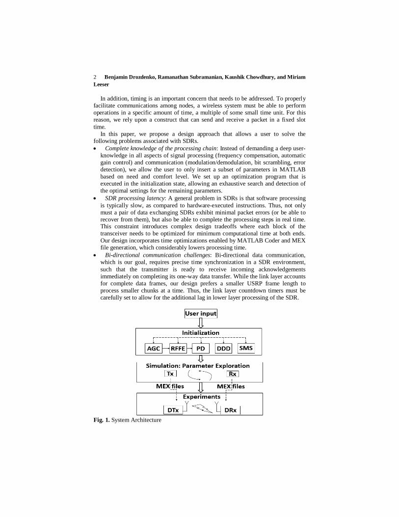
Fig. 1. System Architecture
Implementing a MATLAB-based Self-Configurable Software Defined Radio Transceiver 3
1.1 Design Overview
Our system architecture and operational steps are shown in Fig. 1. In the initialization step, the system allows the user to set a set number of parameters for the entire transceiver chain. We next begin a parameter exploration stage in a simulation-only environment. The transmitter and receiver codes are executed with the user-supplied parameters as constants, and all other possible variations (both in terms of the settings of processing blocks as well as entire algorithms themselves) are considered. From this a feasible set of parameter options are presented that give 99% accuracy in the packet reception rate at the receiver. Note that this is a ‘best case’ scenario, as the actual wireless channel will introduce further channel outages. Once the user selects one of the possible feasible configurations returned by the search, the code is transferred to the actual USRP radios for over-the-air experiments.
Our approach involves first designing a number of (i) state diagrams to reflect the logical and time-dependent operational steps of our system and (ii) block diagrams to reflect the sequential order of operations. Furthermore, we structure the MATLAB code in a way that enables slot time-synchronized operations. For the eventual implementation, we use MATLAB Coder to generate C code. Finally, we compiled the C code into MEX executables that could be called directly from MATLAB on an Ubuntu 64-bit platform that serves as the host computer for the USRPs.
2 Background and Related Work
2.1 Prior and Existing SDR programming tools
An SDR-based test-bed that implements a full-duplex OFDM physical layer and a CSMA link layer along with some strategies for establishing bidirectional communications is described [5]. It involves MATLAB R2013a, MATLAB Coder on USRP-N210 and USRP2 hardware. The PHY layer, based on 802.11a, incorporates timing recovery, frequency recovery, frequency equalization, and error checking. The CSMA link layer involves carrier sensing based on energy detection and stop-and-wait ARQ. However, this approach requires additional development efforts for improving speed and enabling full-duplex.
2.2 IEEE 802.11 and 802.11b
We adopt the IEEE 802.11b physical and medium access control (MAC) layer frame structure specifications in our implementation [9], with some modifications. In MAC header information, we incorporate the Frame Control, Duration/ID, Address 1 and 2 (at 16 bits instead of 32), and Sequence Control. This approach maintains all the MAC header information within 64 bits, which for us is one USRP frame.
4 Benjamin Drozdenko, Ramanathan Subramanian, Kaushik Chowdhury, and Miriam Leeser
2.3 Differential Binary Phase Shift Keying (DBPSK):
We use DBPSK as the differential component enables us to recover a binary sequence from the phase angles of the received signal at any phase offset, without compensating for phase. In addition, DBPSK requires only coarse frequency offset compensation, without any close-loop techniques. If residual frequency offset is less than DBPSK symbol rate, then the bit error rate (BER) approaches theoretical values.
3 Detailed System Design
To clearly identify the transmitting and receiving node for a given SDR pair, we use the terms designated transmitter (DTx) and designated receiver (DRx). This avoids ambiguity in describing a bi-directional communication link, where the transmitter must complete its packet transfer and then switch to a receiver role to get the acknowledgement (ACK). Thus, in the subsequent discussion, the DTx transitions between transmitter and receiver functions alternatively, and vice versa happens for the DRx.
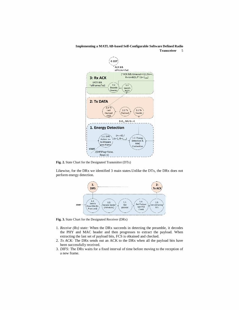
3.1 State Diagrams
In implementing the CSMA/CA-based protocol at the intersection of the link and physical layers, we identify 4 main states (Fig. 2) at the DTx. 1. Energy Detection State: At START, a new packet arrives, and gets stored in a
transmit buffer. The DTx begins sensing energy in the channel. The DTx decides to move either to a backoff state or to a transmit state depending on whether the channel is busy or not. A random amount of time is chosen uniformly from a progressively increasing time interval. DTx continually senses the channel and only when the channel is free, it decrements the backoff time, or freezes it otherwise. When the backoff time counts down to zero, the DTx attempts to transmit.
2. Transmit (Tx) state: In the transmit state, two possibilities exist. The transmission is successful (with the reception of an ACK), or transmission is not successful due to collision with transmissions (with no reception of ACK).
3. Receive (Rx) state: As soon as the transmission is completed, the DTx moves to Rx state, searching and decoding the PLCP header in the received ACK. The DTx then progresses to transmit a new frame and this continues till the last frame is successfully transmitted. On the other hand, if no ACK is received, the DTx enters the backoff state with an increased backoff time and re-attempts transmission.
4. End of transmission state: When transmission is successful, the DTx reaches the end of transmission (EOT) state. Now, the DTx might remain idle or progress to transmit another packet. In the latter case, the DTx re-sets its backoff time and moves into the backoff state for that duration.
Implementing a MATLAB-based Self-Configurable Software Defined Radio Transceiver 5
Fig. 2. State Chart for the Designated Transmitter (DTx)
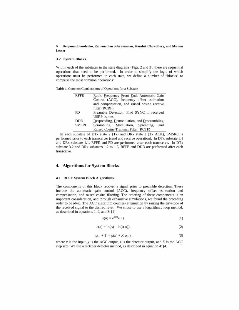
Likewise, for the DRx we identified 3 main states.Unlike the DTx, the DRx does not perform energy detection.
Fig. 3. State Chart for the Designated Receiver (DRx)
1. Receive (Rx) state: When the DRx succeeds in detecting the preamble, it decodes the PHY and MAC header and then progresses to extract the payload. When extracting the last set of payload bits, FCS is obtained and checked.
2. Tx ACK: The DRx sends out an ACK to the DRx when all the payload bits have been successfully received.
3. DIFS: The DRx waits for a fixed interval of time before moving to the reception of a new frame.
6 Benjamin Drozdenko, Ramanathan Subramanian, Kaushik Chowdhury, and Miriam Leeser
3.2 System Blocks
Within each of the substates in the state diagrams (Figs. 2 and 3), there are sequential operations that need to be performed. In order to simplify the logic of which operations must be performed in each state, we define a number of “blocks” to comprise the most common operations:
Table 1. Common Combinations of Operations for a Substate
RFFE Radio Frequency Front End: Automatic Gain Control (AGC), frequency offset estimation and compensation, and raised cosine receive filter (RCRF)
PD Preamble Detection: Find SYNC in received USRP frames
DDD Despreading, Demodulation, and Descrambling SMSRC Scrambling, Modulation, Spreading, and
Raised Cosine Transmit Filter (RCTF) In each substate of DTx state 2 (Tx) and DRx state 2 (Tx ACK), SMSRC is
performed prior to each transceiver (send and receive operation). In DTx substate 3.1 and DRx substate 1.1, RFFE and PD are performed after each transceive. In DTx substate 3.2 and DRx substates 1.2 to 1.5, RFFE and DDD are performed after each transceive.
4. Algorithms for System Blocks
4.1 RFFE System Block Algorithms
The components of this block recover a signal prior to preamble detection. These include the automatic gain control (AGC), frequency offset estimation and compensation, and raised cosine filtering. The ordering of these components is an important consideration, and through exhaustive simulations, we found the preceding order to be ideal. The AGC algorithm counters attenuation by raising the envelope of the received signal to the desired level. We chose to use a logarithmic loop method, as described in equations 1, 2, and 3: [4]
y(n) = eg(n)x(n) . (1)
e(n) = ln(A) – ln(z(m)) . (2)
g(n + 1) = g(n) + K e(n) . (3)
where x is the input, y is the AGC output, z is the detector output, and K is the AGC step size. We use a rectifier detector method, as described in equation 4: [4]
Implementing a MATLAB-based Self-Configurable Software Defined Radio Transceiver 7
z(m) = (1/N) ∑n=mN |y(n)| (4)
where N is the AGC update rate. To accurately estimate the frequency offset between the receiver and the
transmitter, we chose to use an FFT-based method that finds the frequency that maximizes the FFT of the squared signal:
foffset = argmaxf ℱ{x2} (5)
where ℱ denotes the Fast Fourier Transform (FFT).
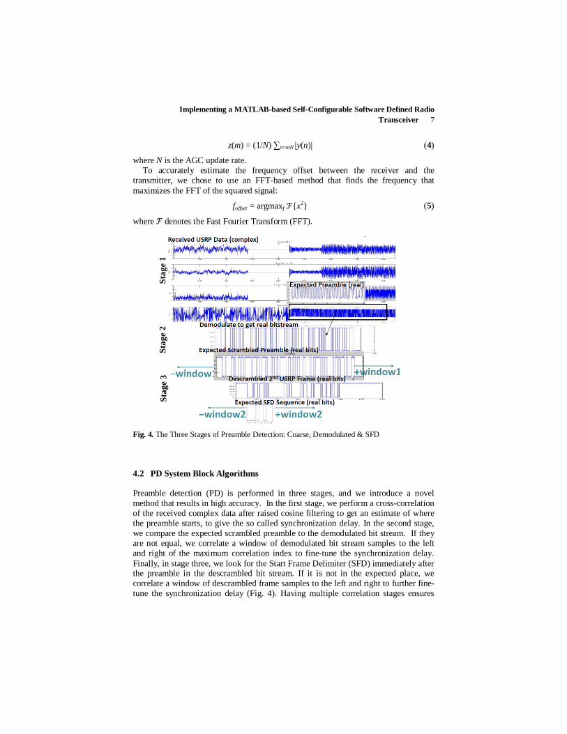
Fig. 4. The Three Stages of Preamble Detection: Coarse, Demodulated & SFD
4.2 PD System Block Algorithms
Preamble detection (PD) is performed in three stages, and we introduce a novel method that results in high accuracy. In the first stage, we perform a cross-correlation of the received complex data after raised cosine filtering to get an estimate of where the preamble starts, to give the so called synchronization delay. In the second stage, we compare the expected scrambled preamble to the demodulated bit stream. If they are not equal, we correlate a window of demodulated bit stream samples to the left and right of the maximum correlation index to fine-tune the synchronization delay. Finally, in stage three, we look for the Start Frame Delimiter (SFD) immediately after the preamble in the descrambled bit stream. If it is not in the expected place, we correlate a window of descrambled frame samples to the left and right to further fine-tune the synchronization delay (Fig. 4). Having multiple correlation stages ensures
Stag
e 1
Stag
e 2
Stag
e 3
8 Benjamin Drozdenko, Ramanathan Subramanian, Kaushik Chowdhury, and Miriam Leeser
that we are able to find the preamble, and hence the start of the PLCP header information, as accurately as possible. However, this accuracy involves a tradeoff in the computational time.
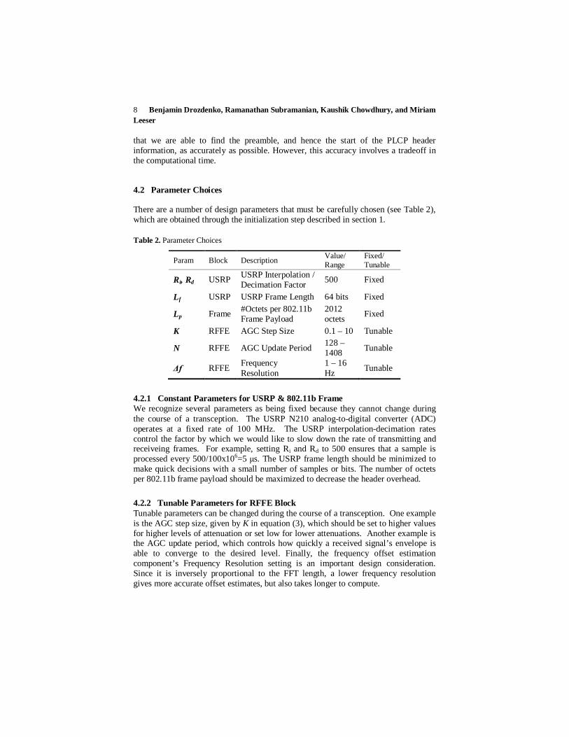
4.2 Parameter Choices
There are a number of design parameters that must be carefully chosen (see Table 2), which are obtained through the initialization step described in section 1.
Table 2. Parameter Choices
Param Block Description Value/ Range
Fixed/ Tunable
Ri, Rd USRP USRP Interpolation / Decimation Factor 500 Fixed
Lf USRP USRP Frame Length 64 bits Fixed
Lp Frame #Octets per 802.11b Frame Payload
2012 octets Fixed
K RFFE AGC Step Size 0.1 – 10 Tunable
N RFFE AGC Update Period 128 –1408 Tunable
Δf RFFE Frequency Resolution
1 – 16 Hz Tunable
4.2.1 Constant Parameters for USRP & 802.11b Frame We recognize several parameters as being fixed because they cannot change during the course of a transception. The USRP N210 analog-to-digital converter (ADC) operates at a fixed rate of 100 MHz. The USRP interpolation-decimation rates control the factor by which we would like to slow down the rate of transmitting and receiveing frames. For example, setting Ri and Rd to 500 ensures that a sample is processed every 500/100x106=5 μs. The USRP frame length should be minimized to make quick decisions with a small number of samples or bits. The number of octets per 802.11b frame payload should be maximized to decrease the header overhead.
4.2.2 Tunable Parameters for RFFE Block Tunable parameters can be changed during the course of a transception. One example is the AGC step size, given by K in equation (3), which should be set to higher values for higher levels of attenuation or set low for lower attenuations. Another example is the AGC update period, which controls how quickly a received signal’s envelope is able to converge to the desired level. Finally, the frequency offset estimation component’s Frequency Resolution setting is an important design consideration. Since it is inversely proportional to the FFT length, a lower frequency resolution gives more accurate offset estimates, but also takes longer to compute.
Implementing a MATLAB-based Self-Configurable Software Defined Radio Transceiver 9
4.3 Code Structure
Any 802.11-style wireless transceiver implementation must have the availability to perform operations based on some slot-based timing. We define this capability as time slot-synchronized operations. For example, before sending a data frame, a station must be able to wait for a backoff (BO) period. Interpreted MATLAB alone lacks the ability to perform time-sensitive operations in this manner, even with actively waiting. For this reason, we rely solely on the USRP for our timing. Our transceive function performs two actions: it gets a frame from, and puts a frame into the USRP buffers at fixed time intervals. Using the value for USRP interpolation/decimation defined in Section 4.2, we can calculate the slot time. Then, we can write our main program while loop so that it calls the transceive function once per loop, running helper functions to prepare data to transmit or process received data based on the active state, as shown in the following program code:
while ~endOfTransmission if (state==Tx) data2Tx = processData2Tx(); end dataRxd = transceive(data2Tx); if (state==Rx) processRxdData(dataRxd); end end
A slot time is defined as the smallest possible unit of time in which our SDR can make a decision. Our system sends or receives a data frame every slot time. The functions we define for processing the received data frame or preparing a new data frame to transmit must complete in less than a slot time to ensure timing accuracy.
5 Experiments
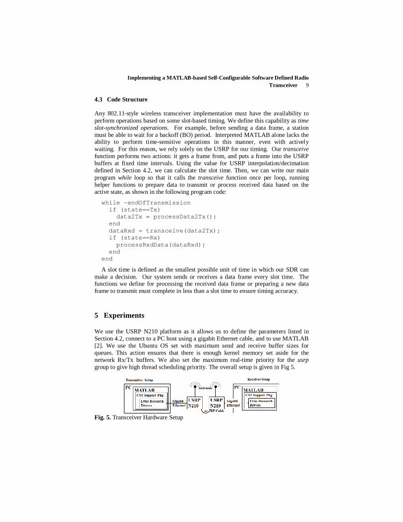
We use the USRP N210 platform as it allows us to define the parameters listed in Section 4.2, connect to a PC host using a gigabit Ethernet cable, and to use MATLAB [2]. We use the Ubuntu OS set with maximum send and receive buffer sizes for queues. This action ensures that there is enough kernel memory set aside for the network Rx/Tx buffers. We also set the maximum real-time priority for the usrp group to give high thread scheduling priority. The overall setup is given in Fig 5.
Fig. 5. Transceiver Hardware Setup
10 Benjamin Drozdenko, Ramanathan Subramanian, Kaushik Chowdhury, and Miriam Leeser
5.1 Communications System Toolbox USRP Support Package
We chose to use Communications System Toolbox System objects for the large part of our design [4]. The comm.AGC System object provides two Detector methods and two Loop methods whose functionality can be contrasted for received signals with varying attenuations. In addition, the PSK coarse frequency offset estimator allows us to shift between FFT-based options. These System objects facilitate easy generation of C code using MATLAB Coder. Here, the comm.SDRuTransmitter System object puts a frame on the USRP transmit buffer, and comm.SDRuReceiver gets a frame from the USRP receive buffer. However, this approach has some disadvantages; e.g., the frame length must now become fixed. Another issue is that running the step methods for these System objects is that they’re single-threaded, whereas the USRP N210 is multi-threaded. On a single clock cycle, this allows to get a frame from the receive buffer or put a frame on the transmit buffer, but not both. Therefore, attempting to write MATLAB code that runs a put and get sequentially will result in an exponentially increasing delay, and eventually result in an overflow of the USRP buffer. To avoid this delay, we plan to explore parallelism and make the transceive function described in section 4.3 operate in a multi-threaded manner. We first generate C code from the MATLAB function using MATLAB Coder.
5.2 MATLAB Coder
MATLAB Coder is used for generating C code. In order to make the MATLAB code acceptable for C code generation, a number of actions must be taken beforehand. All variables are given a static size and type (including real or complex) that does not change in the course of the program. Since System objects cannot be passed into MEX functions, all System objects are declared as persistent variables. The first call to each function, tests whether the persistent variable is empty, and initializes each System object if true. The function code for the transceive, RFFE, DDD, and SMSRC blocks are all prepared in this same manner. We then compile the C code for each major block into a MATLAB executable (MEX) file, which can be called directly from MATLAB.
6 Results
The transceive function is at the core of our system design, since its ability to simultaneously receive and transmit a USRP frame at a near-constant time interval is key to our goal of slot time-synchronized operations. To compare its accuracy, we ran 2,000 time trials to see how long the transceive function takes from start to finish, and how this time difference changes over the course of a longer data bitstream. The timing using a transceive function in interpreted MATLAB and using C code compiled into a MEX are compared in Fig. 6. The timing exhibits some deviation: The function initially overshoots the expected time per USRP frame; on every subsequent iteration it then undershoots to make up for the time difference. Note that
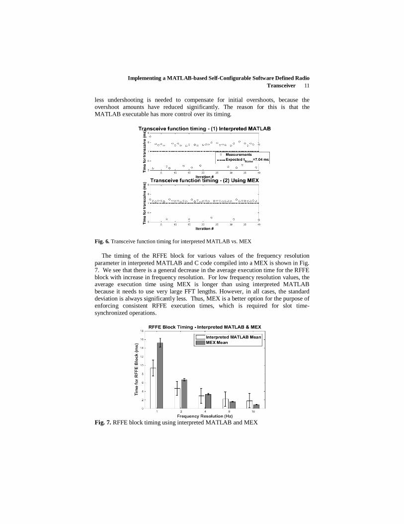
Implementing a MATLAB-based Self-Configurable Software Defined Radio Transceiver 11
less undershooting is needed to compensate for initial overshoots, because the overshoot amounts have reduced significantly. The reason for this is that the MATLAB executable has more control over its timing.
Fig. 6. Transceive function timing for interpreted MATLAB vs. MEX
The timing of the RFFE block for various values of the frequency resolution parameter in interpreted MATLAB and C code compiled into a MEX is shown in Fig. 7. We see that there is a general decrease in the average execution time for the RFFE block with increase in frequency resolution. For low frequency resolution values, the average execution time using MEX is longer than using interpreted MATLAB because it needs to use very large FFT lengths. However, in all cases, the standard deviation is always significantly less. Thus, MEX is a better option for the purpose of enforcing consistent RFFE execution times, which is required for slot time-synchronized operations.
Fig. 7. RFFE block timing using interpreted MATLAB and MEX
12 Benjamin Drozdenko, Ramanathan Subramanian, Kaushik Chowdhury, and Miriam Leeser
Whereas the change to the frequency resolution parameter affects timing directly, the AGC parameters control how well a signal can be recovered under various attenuation levels. By performing a parameter sweep with different values for these parameters, we determined that a step size of 1 and an update period of 1408 minimizes frame misdetection.
7 Conclusion
We conclude that building our design around the concept of slot time-synchronized operations results in a system that adheres to our desired frame time and is able to reconfigure parameter values as needed. Using MEX is essential for realizing timing with little deviation from this frame time. In addition, using MEX is beneficial for improving the speed consistency of our system blocks, most notably RFFE, which can vary its frequency resolution parameter. As part of future work, we will continue towards the complete design of the MAC functions as well as implement our transceiver system design on the Xilinx Zynq-7000 All-Programmable System-on-Chip (APSoC).
Acknowledgments
This work is supported by MathWorks under the Development-Collaboration Research Grant A#: 1-945815398. We would like to thank Mike McLernon and Ethem Sozer for their continued support on this project.
References
1 I. F. Akyildiz, S. Mohanty, M. C. Vuran, and V. Won-Yeol, “NeXt generation/dynamic spectrum access/cognitive radio wireless networks: A survey,” Computer Networks, vol. 500, no. 13, Sept. 2006.
2 Ettus Research, Inc. [Online]. “USRP N200/N210 Networked Series.” 3 IEEE Std 802.11-2009, “Part 11: Wireless LAN Medium Access Control (MAC) and
Physical Layer (PHY) Specifications.” 4 MathWorks Documentation. [Online] . “Communications System Toolbox Documentation.”
“USRP Support Package from Communications System Toolbox.” 5 Travis Collins, “Multi-Node Software Defined Radio TestBed”, NEWSDR 2014. 6 J. Mitola III and G. Q. Maguire, Jr., "Cognitive radio: making software radios more
personal," IEEE Personal Communications Magazine, vol. 6, nr. 4, pp. 13–18, Aug. 1999. 7 M. Luise and R. Reggiannini, "Carrier frequency recovery in all-digital modems for burst-
mode transmissions", IEEE Trans. Commun., vol. 43, no. 3, pp.1169 -1178 1995.