Embed Size (px)
Citation preview

Implementations details of the IEEE 802.11aa
Group Addressed Transmission Service
Pablo Salvador∗†, Luca Cominardi‡, Francesco Gringoli‡, Pablo Serrano†
∗Institute IMDEA Networks, Madrid, Spain
Email: [email protected]†University Carlos III of Madrid, Spain
Email: [email protected]‡University of Brescia, Italy
Email: [email protected],[email protected]
Abstract—In this report we explain and describe the implemen-tation of the 802.11aa protocol and every aspect that concerns thechoices selected and their motivations. We detail all the requiredmodifications at the driver and firmware levels. We also motivatethe choice of the implementation platform.
I. INTRODUCTION
We implement the 802.11aa GATS protocol by means of
the open-source firmware OpenFWWF and the Linux driver
b43. The reason is that we we need to perform some timely
operations only feasible at the firmware level. It is not possible
to implement some of required modifications at higher layers
due to the latency that they introduce, as in some cases
we require to forge frames in less than a SIFS interval
time. All the commons 802.11 wireless devices perform the
acknowledgment procedure at firmware level or directly at
hardware level. The only platform where these mechanisms
can be changed is Broadcom with OpenFWWF firmware.
Other platforms, such as FPGA1 have been considered as
they offer a high degree of flexibility. However, their high
costs make them inappropriate in order to develop scenarios
with large number of receivers.
II. LINUX AND THE WLAN NETWORKS
Linux offers a well developed stack for 802.11 for wireless
devices. There is a high number of developers and users
involved in the creation and maintenance of drivers, and their
integration in the Linux kernel. Recently, companies have
increased their interest in the Open Source philosophy, e.g.,
Intel and Atheros have started to release open source drivers
for Linux. Still, manufacturers do not disclosure some piece
of the software, this is generally the firmware which is the
piece of code that communicates directly with the hardware.
Linux implements a dedicated wireless stack which includes
firmware, driver and 802.11 mac layer. Initially, the 802.11
MAC protocol was managed by the module ieee80211, which
has been progressively replaced by the recent mac80211
module. This module does not handle retransmissions, ACKs,
and other functions that involve very short execution times,
these functionality are delegated to the underlying hardware.
1FPGA: Field-programmable gate array, which is an integrated circuitdesigned to be configured by a customer or a designer after manufacturing
TABLE I802.11 LINUX STACK
Layer 3 and above Stack TCP/IP
Layer 2
Wrapper 802.3 - 802.11mac80211Driver
Firmware
Layer 1 Hardware
Before getting to the 802.11 MAC layer packets are for-
matted as Ethernet frames: the mac80211 module takes the
frame and converts it into a one compliant with the IEEE
802.11 standard. There are appropriate interfaces that allow to
connect user space to the mac80211module, in this way it’s
possible configure the device from user space. Currently the
interface that allow to modify the way in which an interface
works (ad-hoc, managed, etc..) and other parameters such as
channel or rate is nl80211.
The interface based on nl80211 was designed to replace the
old wireless-extension, and leans on the cfg80211module. This
interface is still in active development. The nl80211 is essential
to the realization of the AP mode: module mac80211 does
not incorporate the functionality of the management frame
for that mode, and for a correct use of the device as access
point is necessary to use a program called hostapd. Such
application relies on the nl80211 interface, and handles all
operations typical of an AP: so far the only way to operate
a device in master mode is to use hostapd. Currently the
Linux developers are working in order to make nl80211 the
default interface, the program iwconfig will be replaced by
iw which, together with hostapd, provide powerful tools and
comprehensive management of wireless devices.
III. SOFTWARE OVERVIEW
In this section will be explained and described the driver
modifications necessary to implement the new 802.11aa pro-
tocol. The driver to modify is the open-source driver b43 for
Broadcom wireless chipset [1], we can find the source code
of this driver into the Linux kernel tree.

A. OpenFWWF
OpenFWWF, Open FirmWare for WiFi networks, is an
open-source firmware which implements the 802.11 DCF
mechanism on top of Broadcom wireless cards. Different
operations performed by wireless devices are controlled by
a microprocessor which generally runs a proprietary mi-
crocode/firmware written in assembly language. OpenFWWF
[2] replaces the proprietary firmware with an open source
one for Broadcom devices. The firmware supports all 802.11
primitives in the 2.4GHz band. By modifying the firmware
one can customize the NIC to adhere to a specific MAC given
the basic restrictions, e.g. carrier sensing and CCK and OFDM
modulations.
The internal units of the MAC processor allow the exchange
of data via two main routes: the path to the transmit (TX)
and one for receive (RX). To cope with different tasks, the
firmware is built as a main loop that responds to external
conditions, such as the arrival of a new frame, an indication
of free channel and the expiration of the internal timer2. The
key elements include:
• The FIFO queues for the TX and RX: the MAC
processor takes the frame from one of the Tx queues
and puts them into the serializer when can make a
transmission. In the other direction, the MAC processor
takes the frames received from the buffer of Rx queue
and raises an IRQ in such a way that the host kernel can
properly retrieve the frame;
• The internal shared memory (SHM): in this memory
the MAC processor maintains several state variables that
can be read or modified by the host kernel;
• The template RAM: the MAC processor can compose
an arbitrary frame in this region of memory and then
transmit the result as if it was coming from the FIFO
queue of TX;
• The internal registers and external conditions (EC):
the MAC processor changes these hardware registers in
response to changes in the EC, to program the radio
interface and set the timer correctly.
The current versions of the Linux kernel uses the mac80211
module for the development of device drivers. mac80211 is an
abstraction layer that allows you to interface the network stack
of the kernel with most of the low-level driver for wireless
devices. The rate control algorithm [3], [4], for example, is
generally implemented within mac80211 and shared by all the
drivers. These drivers also offer an interface with respect to
all the operations of low level defined by the 802.11 standard
that, as already said many times, are performed by firmware
or hardware due the timing’s problems.
When the b43 module is loaded the driver initializes the
device providing:
• ucode: Firmware image, namely the code that will be
executed by the CPU on the NIC.
• pcm: File that manages the encryption capabilities in
2http://bcm-v4.sipsolutions.net/802.11/Microcode
TABLE IIBITMAP OF THE QUEUES AT FIRMWARE LEVEL
bit QoS queue
0x0001 Background
0x0002 Best Effort
0x0004 Video
0x0008 Voice
0x0010 Multicast
hardware. Its presence is not indispensable at the time
that OpenFWWF not support such acceleration.
• initvals: File that initializes a set of registers with specific
values, e.g.: the slot time duration (SlotTime) or the SIFS.
There are different types of files depending on the revision
of the firmware on the device: in our case we use the
files: ucode5.fw, b0g0initvals5.fw and pcm5.fw3, which are
compatible with hardware revisions between 5 and 10.
We use the b43-tools [5] to assemble/disassemble and debug
the firmware:
• b43-asm: Assembler.
• b43-dasm: Disassembler.
• b43-fwdump: Debugger to dump of the content of
firmware’s register or the SHM.
B. Features overview
In this section we describe some firmware features, in
particular the hardware registers that we rely on to implement
802.11aa.
a) SPR TXE0 FIFO RDY: This special purpose register
checks if there is a frame ready in one of the queues. This
register behaves like a bitmap, i.e., each bit indicates the FIFO
queue that has a frame ready to transmit. Table II reports the
bitmap of these queues.
b) [SHM TXFCUR]: This register stores the number of
the current transmission.
c) SPR TXE0 SELECT: This special purpose register
selects one of the three available operations on a given queue
or on the raw template memory. The meaning of each bit is
explained in the following:
• bit 0x0003: Each combination of these two bits executes
a specific operation.
– 0: No operation.
– 1: Copy in SHM up to the end of the current
packet or the number of bytes written in
SPR TXE0 TX COUNT. Destination address is
stored into SPR TXE0 TX SHM ADDR. Source
address is either SPR TXE0 Template TX Pointer
when operating on raw template, or
SPR TXE0 FIFO HOL CURPTR when operating
on a FIFO queue.
– 2: Select for transmission during the scheduled
opportunity up to the end of the current packet or the
number of bytes written in SPR TXE0 TX COUNT.
Starts from SPR TXE0 Template TX Pointer
3This file is only required for Linksys routers WRT54GL

when operating on raw template, or
SPR TXE0 FIFO HOL CURPTR when operating
on a FIFO queue.
– 3: Advance SPR TXE0 FIFO HOL CURPTR when
operating on a FIFO queue, the number of
bytes added to the pointer is the value in
SPR TXE0 TX COUNT.
• bit 0x0004:
– 0: Work up to the end of the packet in the FIFO
queue.
– 1: Work up to the number of bytes written in
SPR TXE0 TX COUNT.
• bit 0x0020: Set to 1 when asking transmission of a given
number of bytes as written in SPR TXE0 TX COUNT,
must be zero in all other cases and operations.
• bit 0x0700: The number of the FIFO queue on which the
operation must be performed.
• bit 0x0800: The possible values, with their meanings, are
the following:
– 0: Operate on a FIFO queue.
– 1: Operate on raw template.
d) SPR TXE0 FIFO CMD: This special purpose regis-
ter sets up the Transmission Engine (TE). This register must
be set to:
SPR TXE0 FIFO CMD = (queue# ≪ 8) | CMD
The values of CMD are the following:
• 0x2000: Move SPR TXE0 FIFO HOL and
SPR TXE0 FIFO HOL CURPTR to byte zero of
the next packet in the queue. This recycles the space left
available to load more packets from the corresponding
external queue, how many depends on the length of the
new packets, might also be zero.
• 0x4000: restores SPR TXE0 FIFO HOL CURPTR to
SPR TXE0 FIFO HOL to the begging of the HOL
packet in the queue.
e) spr0a5: Only the three less significant bits can be set.
Its value is 0x7 but nothing, apparently, changes with other
values.
f) COND STA MODE: This condition evaluates true in
managed, monitor and AP mode, false in ad-hoc.
g) COND AP MODE : This condition evaluates true in
AP mode.
h) Notes: When we transmit a packet from a FIFO
queue, the firmware first copies the packet into the Template
RAM and afterwards transmits it from it. Then, you can
still modify a packet when it is in the template before its
transmission. The transmission operation fetches bytes from
the FIFO image in the template and buffers them somewhere
in the Transmission Engine at a very high speed. Actual
transmission may start at the same time.
When working on given number of bytes from a FIFO
queue, transmission and copy can be requested beyond the
end of the current packet but within the next 32-bit boundary,
i.e., up to three bytes more can be transmitted if allowed by
the length of the packet.
When the PLCP is wrong with respect to the number of
bytes requested or in the queue, the transmission will start
but it will trigger PHY transmission errors visible executing
the command dmesg, which prints the message buffer of the
kernel. We can imagine that the Transmission Engine simply
expects a given number of bytes but it receives less than
expected and the transmission is interrupted. Sometimes we
noticed the rest of the packet being actually transmitted and
padded with zeros.
The images of the external FIFO in the template are rings.
This means that a packet can cross the FIFO end boundary. The
Transmission Engine will take care of this when transmitting.
IV. PLATFORM OVERVIEW
We implement GATS mechanisms on Alix 2d2 boxes by
PC Engines,4 which embed a Geode LX800 AMD 500 MHz
CPU, 256 MB DDR DRAM, 2 mini-PCI slots and a Compact
Flash (CF) socket. The CF card is equipped with a light
Ubuntu server distribution (10.04) and as kernel we use a
2.6.36 version5.
Each device embeds a Broadcom BCM94318MPG
802.11b/g wireless chipset, which supports the open-source
driver b43 [1] and the OpenFWWF firmware.
The files to modify at the driver level can be found in the
following path:
user@celeborn ˜/linux-2.6.36/drivers/net/wireless/
b43 \$
V. REQUIRED MODIFICATIONS
In this section we detail the modifications carried out at
the driver and firmware level in order to implement the new
802.11aa protocol.
A. Common driver modifications
A common modification in all the mechanisms is to mark
the groupcast packets. For that reason, we define a specific
UDP port for that kind of traffic, so when the driver and the
firmware receive a packet directed to this special port, they
enable the proper GATS mechanism. The choice of the port is
arbitrary but being aware not to collide with a reserved UDP
port, so we decide to use the port 48879. The use of UDP
is mandatory because as we transmit ”multicast” traffic and
the use of a connection oriented protocol, e.g. TCP, would be
more problematic.
To carry on with this modification we made a library
function that inspects the packet and returns a boolean value
based on whether the packet is UDP and the destination port
is set to 0xBEEF (48879). We modify the utility file, util.c.
...
bool ieee80211_fragment_is_80211aa(void* _buff, int len)
{
u8* buff = (u8*) _buff;
4http://www.pcengines.ch/5http://www.kernel.org/pub/linux/kernel/v2.6/linux-2.6.36.4.tar.gz

if(len >= 60 && // we have enough bytes to
make the following checks
buff[24] == 0xAA && // normal LLC
buff[25] == 0xAA &&
buff[30] == 0x08 && // carrying IP
buff[31] == 0x00 &&
buff[32] == 0x45 )
{
if( buff[41] == 0x11 ) // UDP
{
int dport = buff[54] << 8 | buff
[55];
if(dport == 0xBEEF)
return true;
}
}
return false;
}
EXPORT_SYMBOL(ieee80211_fragment_is_80211aa);
At the mac80211 layer we modify its header file:
user@celeborn ˜/linux-2.6.36/include/net/ \$
mac80211.h
The modification of this header is very simple and consists
only of adding the prototype of the function described above.
...
/* The prototype of the function */
bool ieee80211_fragment_is_80211aa(void* buff, int len);
#endif /* MAC80211_H */
Before starting to explain in detail the implementation for
each layer we present a high-level description for the driver
and firmware of every solution.
VI. DIRECTED MULTICAST SERVICE
The DMS system basically consists in splitting a multicast
flow into a various unicast flows. To do this we need to know
the MAC address of each associated client, if we have this
information becomes very simple to modify the driver.
A. Driver modifications
Fig. 1 reports the flowchart that represents the high-level
behavior of the driver for the DMS case, which can can be
summarized as follows:
1) Check if the incoming frame is an 802.11aa frame.
2) If it is an 802.11aa frame, replace the destination MAC
address with the MAC address of the selected station.
3) Transmit the frame to the DMA6
4) Check if we have sent the frame to all stations.
5) If it is not the last station, return to 2.
1) b43 header: We change the main header of the driver,
b43.h. In this file file we add some definition and variables
used for debugging purpose.
...
/* 80211aa define */
#define 80211aa_DEBUG 1
/* the offset of the destination mac address into skb->data
*/
#define DST_MAC_ADDR_OFF 4
6DMA: Direct Memory Access, it allows certain hardware subsystemswithin the computer to access system memory independently of the centralprocessing unit (CPU).
Fig. 1. Flowchart of the driver implementation of the DMS mechanism.
/* the maximum number of associated clients */
#define NUM_STAS 100
/* the global index of last associated station */
extern int last_client_index;
/* the global list of the associated clients */
extern u8 assoc_client[NUM_STAS][ETH_ALEN];
...
...
/* Data structure for one wireless device (802.11 core) */
struct b43_wldev {
...
#ifdef 80211aa_DEBUG
/* these variable are used only for debugging
purpose */
unsigned int tx_frame_80211aa;
unsigned int rx_frame_80211aa;
#endif
};
...
2) Main: The core of DMS mechanism is the main file,
main.c, in which we add a variable to store the MAC address
of the associated stations.
...
/* the double array that contains the all mac address of
associated station */
u8 assoc_client[NUM_STAS][ETH_ALEN];
/* the index of last associated station, we keep the count
*/
int last_client_index = -1;
...
Then, we modify the function that sends the packet to the
DMA. We check if it is a 802.11aa packet, if so we send
the same frame a number of times equal to the number of
stations. Each time we send an 802.11aa frame we change the
destination MAC with that of the selected station.
...
static void b43_tx_work(struct work_struct *work)
{
...
struct sk_buff *skb;
struct sk_buff *skb_c;
...
while (skb_queue_len(&wl->tx_queue)) {
skb = skb_dequeue(&wl->tx_queue);
if(ieee80211_fragment_is_80211aa(skb->data,
skb->len)) {
/* send the same frame to every associated
station */
for(i = 0; i <= last_client_index; i++) {
if(i == last_client_index)
skb_c = skb;
else
skb_c = skb_copy(skb, GFP_ATOMIC);
skb_c->data[DST_MAC_ADDR_OFF+0] =
assoc_client[i][0];
skb_c->data[DST_MAC_ADDR_OFF+1] =
assoc_client[i][1];
skb_c->data[DST_MAC_ADDR_OFF+2] =
assoc_client[i][2];
skb_c->data[DST_MAC_ADDR_OFF+3] =
assoc_client[i][3];
skb_c->data[DST_MAC_ADDR_OFF+4] =
assoc_client[i][4];
skb_c->data[DST_MAC_ADDR_OFF+5] =
assoc_client[i][5];
if (b43_using_pio_transfers(dev))
err = b43_pio_tx(dev, skb_c);
else
err = b43_dma_tx(dev, skb_c);
#ifdef 80211aa_DEBUG
dev->tx_frame_80211aa++;
#endif
if (unlikely(err))
dev_kfree_skb(skb_c); /* Drop it */
}
}
else {
if (b43_using_pio_transfers(dev))
err = b43_pio_tx(dev, skb);
else
err = b43_dma_tx(dev, skb);
if (unlikely(err))
dev_kfree_skb(skb); /* Drop it */
}
}
...
}
...
3) Xmit: As we deal with a multicast flow turned into
multiple unicast flows we communicate to the firmware that
the 802.11aa frames require to be acknowledged. To this aim,
we modify in the xmit.c file the MAC control field into the
special header for the b43 devices.
...
int b43_generate_txhdr(struct b43_wldev *dev,
u8 *_txhdr,
struct sk_buff *skb_frag,
struct ieee80211_tx_info *info,
u16 cookie)
{
...
/* MAC control */
if (!(info->flags & IEEE80211_TX_CTL_NO_ACK))
mac_ctl |= B43_TXH_MAC_ACK;
/* Force ACK timeout for 80211aa frames */
if(ieee80211_fragment_is_80211aa((void*)
fragment_data, fragment_len))
mac_ctl |= B43_TXH_MAC_ACK;
...
}
...
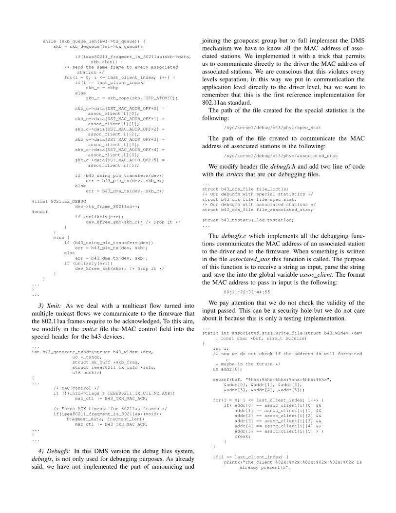
4) Debugfs: In this DMS version the debug files system,
debugfs, is not only used for debugging purposes. As already
said, we have not implemented the part of announcing and
joining the groupcast group but to full implement the DMS
mechanism we have to know all the MAC address of asso-
ciated stations. We implemented it with a trick that permits
us to communicate directly to the driver the MAC address of
associated stations. We are conscious that this violates every
levels separation, in this way we put in communication the
application level directly to the driver level, but we want to
remember that this is the first reference implementation for
802.11aa standard.
The path of the file created for the special statistics is the
following:
/sys/kernel/debug/b43/phy*/spec_stat
The path of the file created to communicate the MAC
address of associated stations is the following:
/sys/kernel/debug/b43/phy*/associated_stas
We modify header file debugfs.h and add two line of code
with the structs that are our debugging files.
...
struct b43_dfs_file file_loctls;
/* Our debugfs with special statistics */
struct b43_dfs_file file_spec_stat;
/* Our debugfs with associated stations */
struct b43_dfs_file file_associated_stas;
struct b43_txstatus_log txstatlog;
...
The debugfs.c which implements all the debugging func-
tions communicates the MAC address of an associated station
to the driver and to the firmware. When something is written
in the file associated stas this function is called. The purpose
of this function is to receive a string as input, parse the string
and save the into the global variable assoc client. The format
the MAC address to pass in input is the following:
00:11:22:33:44:55
We pay attention that we do not check the validity of the
input passed. This can be a security hole but we do not care
about it because this is only a testing implementation.
...
static int associated_stas_write_file(struct b43_wldev *dev
, const char *buf, size_t bufsize)
{
int i;
/* now we do not check if the address is well formatted
,
* maybe in the future */
u8 addr[6];
sscanf(buf, "%hhx:%hhx:%hhx:%hhx:%hhx:%hhx",
&addr[0], &addr[1], &addr[2],
&addr[3], &addr[4], &addr[5]);
for(i = 0; i <= last_client_index; i++) {
if( addr[0] == assoc_client[i][0] &&
addr[1] == assoc_client[i][1] &&
addr[2] == assoc_client[i][2] &&
addr[3] == assoc_client[i][3] &&
addr[4] == assoc_client[i][4] &&
addr[5] == assoc_client[i][5] ) {
break;
}
}
if(i <= last_client_index) {
printk("The client %02x:%02x:%02x:%02x:%02x:%02x is
already present\n",

addr[0], addr[1], addr[2], addr[3], addr
[4], addr[5]);
return -1;
}
if(last_client_index+1 >= NUM_STAS) {
printk("Reached the maximum number for the
associated client, can’t add %02x:%02x:%02x:%02
x:%02x:%02x\n",
addr[0], addr[1], addr[2], addr[3], addr[4],
addr[5]);
return -1;
}
last_client_index++;
for(i = 0; i < ETH_ALEN; i++)
assoc_client[last_client_index][i] = addr[i];
printk("New client associated:\t%02x:%02x:%02x:%02x:%02
x:%02x\n",
assoc_client[last_client_index][0],
assoc_client[last_client_index][1],
assoc_client[last_client_index][2],
assoc_client[last_client_index][3],
assoc_client[last_client_index][4],
assoc_client[last_client_index][5]);
return 0;
}
...
This function is called when the file associated stas is read.
This function is not necessary for a correct working of DMS
mechanism but is useful to check if the MAC addresses of
associated stations are stored correctly.
...
static ssize_t associated_stas_read_file(struct b43_wldev *dev, char *buf, size_t bufsize)
{
ssize_t count = 0;
unsigned long flags;
int i;
spin_lock_irqsave(&dev->wl->hardirq_lock, flags);
for(i = 0; i <= last_client_index; i++) {
fappend("%02x:%02x:%02x:%02x:%02x:%02x\n",
assoc_client[i][0], assoc_client[i][1],
assoc_client[i][2],
assoc_client[i][3], assoc_client[i][4],
assoc_client[i][5]);
}
// Unlock the spin
spin_unlock_irqrestore(&dev->wl->hardirq_lock, flags);
return count;
}
...
When we read the file spec stat that we have created into
the debugfs, the kernel calls this function that takes care to
recover all current values from the device and to write them
into the debugfs file.
...
static ssize_t spec_stat_read_file(struct b43_wldev *dev,
char *buf, size_t bufsize)
{
ssize_t count = 0;
unsigned long flags;
unsigned int high, low, qos_queue;
// Lock the spin
spin_lock_irqsave(&dev->wl->hardirq_lock, flags);
// DRIVER LEVEL
fappend("DRIVER LEVEL:\n\n");
fappend("80211aa frames sent: %d\n", dev->
tx_frame_80211aa);
fappend("80211aa frames received: %d\n", dev->
rx_frame_80211aa);
spin_unlock_irqrestore(&dev->wl->hardirq_lock, flags);
return count;
}
...
The last step is to communicate to the kernel the right
function to use when we access the files in reading and writing.
We do this adding these few lines:
...
B43_DEBUGFS_FOPS(loctls, loctls_read_file, NULL);
/* Our debugfs with special statistics */
/* B43_DEBUGFS_FOPS(debugs_fs_file,
* function_called_on_reading,
* function_called_on_writing); */
B43_DEBUGFS_FOPS(spec_stat, spec_stat_read_file, NULL);
/* Our debugfs with associated stations */
B43_DEBUGFS_FOPS(associated_stas, associated_stas_read_file
, associated_stas_write_file);
...
...
ADD_FILE(loctls, 0400);
/* Our debugfs with special statistics */
/* ADD_FILE(debufs_fs_file, permissions_definition)
*/
ADD_FILE(spec_stat, 0600);
/* Our debugfs with associated stations */
ADD_FILE(associated_stas, 0700);
...
...
debugfs_remove(e->file_loctls.dentry);
/* Our debugfs with special statistics */
/* debugfs_remove(e->debug_fs_file.dentry); */
debugfs_remove(e->file_spec_stat.dentry);
/* Our debugfs with associated stations */
debugfs_remove(e->file_associated_stas.dentry);
...
B. Firmware modifications
To implement the DMS mechanism we do not require to
modify anything at the firmware. We just turn each a multicast
flow into a multiple unicast flow, and this operation is handled
at driver level as explained before.
VII. GCR UNSOLICITED RETRY
The GCR Unsolicited Retry consists in retransmitting the
same frame R times without expecting any ACK. Overall,
the GCR Unsolicited Retry behaves ”exactly” as the legacy
multicast system, apart from the frame retransmissions. This
only requires a small change in the firmware. Moreover,
we perform changes at the driver level, to communicate the
firmware that the transmitted frame is 802.11aa type and
manage it accordingly.
A. Driver modification
Fig. 2 reports the flowchart that represents the high-live
behavior of the driver, which can be enumerated as follows:
1) Check if the incoming frame is an 802.11aa frame.
2) If it is an 802.11aa frame, replace the destination MAC
address with the groupcast address.
3) Transmit the frame to the DMA.

Fig. 2. Flowchart of driver implementation of the GCR UR mechanism.
1) b43 header: We change the main header of the driver,
b43.h. In this file file we add some definition and variables
used for debugging purpose.
...
/* 80211aa define */
#define 80211aa_DEBUG 1
/* the offset of the destination mac address into skb->data
*/
#define DST_MAC_ADDR_OFF 4
...
...
/* Data structure for one wireless device (802.11 core) */
struct b43_wldev {
...
#ifdef 80211aa_DEBUG
/* these variable are used only for debugging
purpose */
unsigned int tx_frame_80211aa;
unsigned int rx_frame_80211aa;
#endif
};
...
2) DMA: The GCR Unsolicited Retry version is quite
simple to implement, we only have to put the legacy frames
in a queue and the 8021aa ones in another. We separate
the frames into 2 queues because the implementation of the
firmware code will result easier. To do this, we add and modify
some function into the management of the DMA, namely
dma.c.
We modify the standard function for the selection of the
queue. We comment all the code inside this function and we
force to select the ring relative to the background queue. We
call this function only in case that we are transmitting legacy
frames.
...
/* Static mapping of mac80211’s queues (priorities) to b43
DMA rings. */
static struct b43_dmaring *select_ring_by_priority(struct
b43_wldev *dev, u8 queue_prio)
{
struct b43_dmaring *ring;
// if (dev->qos_enabled) {
// 0 = highest priority
// switch (queue_prio) {
// default:
// B43_WARN_ON(1);
// case 0:
// ring = dev->dma.tx_ring_AC_VO;
// break;
// case 1:
// ring = dev->dma.tx_ring_AC_VI;
// break;
// case 2:
// ring = dev->dma.tx_ring_AC_BE;
// break;
// case 3:
// ring = dev->dma.tx_ring_AC_BK;
// break;
// }
// } else
// ring = dev->dma.tx_ring_AC_BE;
// We put the normal frame always in the first
queue (queue 0 at firmware level)
ring = dev->dma.tx_ring_AC_BK;
return ring;
}
...
Later we add a function that selects the right ring for the
802.11aa frames. We put each frame into the best effort queue.
...
static struct b43_dmaring *select_ring_by_priority_80211aa(
struct b43_wldev *dev)
{
struct b43_dmaring *ring;
ring = dev->dma.tx_ring_AC_BE;
#ifdef 80211aa_DEBUG
dev->tx_count_qos[QOS_QUEUE_BESTEFFORT]++;
#endif
return ring;
}
...
At the moment to transmit to the DMA, we check if is an
802.11aa frame or not. If it is so, we call the selection of the
queue for these kind of frames, otherwise we call the standard
function.
...
int b43_dma_tx(struct b43_wldev *dev, struct sk_buff *skb)
{
struct b43_dmaring *ring;
struct ieee80211_hdr *hdr;
int err = 0;
struct ieee80211_tx_info *info = IEEE80211_SKB_CB(
skb);
hdr = (struct ieee80211_hdr *)skb->data;
if (info->flags & IEEE80211_TX_CTL_SEND_AFTER_DTIM)
{
/* The multicast ring will be sent after
the DTIM */
/* We manage the multicast frame like a
unicast frame here
* we put them in the same dma_ring */
//ring = dev->dma.tx_ring_mcast;
ring = select_ring_by_priority(dev,
skb_get_queue_mapping(skb));
/* Set the more-data bit. Ucode will clear
it on

* the last frame for us. */
hdr->frame_control |= cpu_to_le16(
IEEE80211_FCTL_MOREDATA);
} else {
/* Decide by priority where to put this
frame. */
/* if the frame is a 80211aa frame, the
ring will be chosen in round robin mode
*/
if(ieee80211_fragment_is_80211aa(skb->data,
skb->len))
{
ring =
select_ring_by_priority_80211aa
(dev);
#ifdef 80211aa_DEBUG
dev->tx_frame_80211aa++;
#endif
}
else
{
ring = select_ring_by_priority(dev,
skb_get_queue_mapping(skb));
}
}
...
3) Xmit: Another change at driver level is the management
of the acknowledgment. We communicate the firmware that
the 802.11aa frames do not need an ACK, so we disable it.
This is done by modifying in the xmit.c function the MAC
control field into the special header for the b43 devices.
...
int b43_generate_txhdr(struct b43_wldev *dev,
u8 *_txhdr,
struct sk_buff *skb_frag,
struct ieee80211_tx_info *info,
u16 cookie)
{
...
/* MAC control */
if (!(info->flags & IEEE80211_TX_CTL_NO_ACK))
mac_ctl |= B43_TXH_MAC_ACK;
/* Disable ACK timeout for 80211aa frames */
if(ieee80211_fragment_is_80211aa((void*)
fragment_data, fragment_len))
mac_ctl &= ˜B43_TXH_MAC_ACK;
...
}
...
We are sending and receiving a groupcast frames and since
there is no management by the module MLME, we restore the
destination mac address of the packet with the mac address of
device. This does not affect in any way our tests because the
transmission and reception have already occurred.
...
void b43_rx(struct b43_wldev *dev, struct sk_buff *skb,
const void *_rxhdr)
{
...
status.antenna = !!(phystat0 & B43_RX_PHYST0_ANT);
if(ieee80211_fragment_is_80211aa(skb->data, skb->
len)) {
/* restore the dest mac address */
skb->data[DST_MAC_ADDR_OFF + 0] = dev->wl->mac_addr
[0];
skb->data[DST_MAC_ADDR_OFF + 1] = dev->wl->mac_addr
[1];
skb->data[DST_MAC_ADDR_OFF + 2] = dev->wl->mac_addr
[2];
skb->data[DST_MAC_ADDR_OFF + 3] = dev->wl->mac_addr
[3];
skb->data[DST_MAC_ADDR_OFF + 4] = dev->wl->mac_addr
[4];
skb->data[DST_MAC_ADDR_OFF + 5] = dev->wl->mac_addr
[5];
#ifdef 80211aa_DEBUG
dev->rx_frame_80211aa++;
#endif
}
...
}
...
4) Debugfs: These modifications are strictly related to the
debugging purpose. As already explained before, we need
to read some values from the wireless device because some
information are retrievable only by the firmware. The path of
the file of debug created is the following:
/sys/kernel/debug/b43/phy*/spec_stat
We modify header file debugfs.h and add two line of code
with the structs that are our debugging files.
...
struct b43_dfs_file file_loctls;
/* Our debugfs with special statistics */
struct b43_dfs_file file_spec_stat;
struct b43_txstatus_log txstatlog;
...
The path of the debugfs into b43 driver where are imple-
mented all the debugging functions is the following:
user@celeborn ˜/linux-2.6.36/drivers/net/wireless/
b43 \$ debugfs.c
The following function permits to read the values exported
through debugfs. When we access on reading the file that we
have created into the debugfs, the kernel calls this function
that takes care to recover all current values from the device
and to write them into the debugfs file.
...
static ssize_t spec_stat_read_file(struct b43_wldev *dev,
char *buf, size_t bufsize)
{
ssize_t count = 0;
unsigned long flags;
unsigned int high, low, qos_queue;
// Lock the spin
spin_lock_irqsave(&dev->wl->hardirq_lock, flags);
// DRIVER LEVEL
fappend("DRIVER LEVEL:\n\n");
fappend("80211aa frames sent: %d\n", dev->
tx_frame_80211aa);
fappend("80211aa frames received: %d\n", dev->
rx_frame_80211aa);
// Unlock the spin
spin_unlock_irqrestore(&dev->wl->hardirq_lock, flags);
return count;
}
...
The last step is to communicate to the kernel the right
function to use when we access the file in reading. We do
this adding these few lines:
...
B43_DEBUGFS_FOPS(loctls, loctls_read_file, NULL);
/* Our debugfs with special statistics */
/* B43_DEBUGFS_FOPS(debugs_fs_file,
* function_called_on_reading,
* function_called_on_writing); */
B43_DEBUGFS_FOPS(spec_stat, spec_stat_read_file, NULL);
...

Fig. 3. Flowchart of the firmware implementation of the GCR UnsolicitedRetry mechanism.
...
ADD_FILE(loctls, 0400);
/* Our debugfs with special statistics */
/* ADD_FILE(debufs_fs_file, permissions_definition)
*/
ADD_FILE(spec_stat, 0600);
#undef ADD_FILE
...
...
debugfs_remove(e->file_loctls.dentry);
/* Our debugfs with special statistics */
/* debugs_remove(e->debug_fs_file.dentry); */
debugfs_remove(e->file_spec_stat.dentry);
debugfs_remove(e->subdir);
...
B. Firmware modifications
Fig. 3 reports the flowchart that represents the high-level
behavior of the firmware, which can be summarized as fol-
lows:
1) Transmit the frame.
2) If it is an 802.11aa frame, check if we have already sent
it R times; if not, return to 1.
3) Flush the frame and report the transmission status to the
driver.
For implementing GCR UR at firmware level we must keep
in mind the following:
1) The groupcast MAC address assignment is statically
configured as we have already said that the manage-
ment procedure implementation and the mechanism to
announce and join the groupcast group is out-of scope.
2) The destination MAC address of outgoing packets from
the AP must be changed to the groupcast address.
3) The receiver must recognize the groupcast packets and
send them up at driver level.
4) The groupcast frame must be transmitted R times.
a) Shared memory: To pass information from the
firmware to the driver and vice versa we use the shared
memory. First, we add some definition strictly related to the
functioning of the firmware, which communicates the driver
that QoS is supported, so the driver enables all the queues.
b) Registers: To implement the 80211aa mechanism we
store some values during the firmware execution, e.g., the
number of frames sent. We have 18 registers available that
we can use as we wish. The free registers are the register
from REG46 to REG63.
c) Common definitions: We define the groupcast address
for both sender and receiver.
...
#define BEACON0_TEMPLATE_ADDR 0x0068
#define BEACON1_TEMPLATE_ADDR 0x0468
/* the groupcast group address
* the notation is the network one -> be:ef:be:ef:be:ef */
#define MCAST_GROUP_ADDR1 0xefbe
#define MCAST_GROUP_ADDR2 0xefbe
#define MCAST_GROUP_ADDR3 0xefbe
#define NEED_BEACON (MASK(COND_NEED_BEACON))
#define NEED_RESPONSEFR (MASK(COND_NEED_RESPONSEFR)
)
...
1) Transmitter: We implement the transmission of the
groupcast frames an arbitrary number of times R without
expecting any ACK frame. Then, we define how many times
the firmware has to transmit the same frame, which can be
configured to any integer. However for latency reasons we
just use values between 1 and 8, following the value of the
802.11 long retry.
#define NUM_RESEND_FRAME 4
Following, we communicate the driver that the firmware
supports the QoS. We also modify the behavior of queue
selection, by using only 2 queues: one for unicast traffic and
the other for 802.11aa frames. At the time when we load
the header of the packet into the shared memory we check
the queue bitmap SPR TXE0 FIFO RDY and properly update
[SHM TXFCUR].
Following, when we transmit a packet and the
[SHM TXFCUR] is non-zero it means that we are transmitting
an 802.11aa frame, in this case we update the destination
MAC address to the groupcast one. Once the frame is sent R
times we flush the queue.
2) Receiver: At the reception, when the firmware receives a
packet addressed to its source MAC address ot to the multicast
address, it sends it to upper layers. The groupcast address is
not a multicast address7. So, we modify the firmware to not
discard the groupcast frames.
check_frame_subtype:
...
srxh REG19 & 3, REG34
je REG34, 0x001, rx_control_frame
jext COND_RX_RAMATCH, rx_frame_and_ra_match
/* check the first byte of address1 */
MOV(MCAST_GROUP_ADDR1, TMP1)
7An 802.11 multicast address has the less significative bit of the first octetset to 1

jne [RX_FRAME_ADDR1_1,off1], TMP1,
check_frame_subtype_continue
/* check the second byte of address1 */
MOV(MCAST_GROUP_ADDR2, TMP1)
jne [RX_FRAME_ADDR1_2,off1], TMP1,
check_frame_subtype_continue
/* check the third byte of address1 */
MOV(MCAST_GROUP_ADDR3, TMP1)
jne [RX_FRAME_ADDR1_3,off1], TMP1,
check_frame_subtype_continue
jext COND_TRUE, send_frame_to_host_continue
check_frame_subtype_continue:
...
VIII. GCR BLOCK ACKNOWLEDGEMENT
The GCR Block Acknowledgement is the most complex
scheme among the 802.11aa GATS mechanisms. First, we
must manage the retransmissions. In 802.11 unicast mech-
anism the retransmissions are handled by the firmware and
only involves one frame at a time. The maximum number of
times that a frame can be retransmitted is variable. The 802.11
standard defines two different retry limits:
• long retry: A frame can be retransmitted up to 4 times.
• short retry: A frame can be retransmitted up to 7 times.
A transmitter may choose which limit to use and this will
be very useful in this implementation. As already said the
commodity 802.11 hardware is very limited so we have to
examine the capabilities of the BCM4318 hardware and find a
way to retransmit at least up to 4 times a burst of 64 frames.
Furthermore, for this scheme we must keep the operation status
as we send a burst of frames and following we perform the
Block Ack polling procedure to each associated station. Then,
we must resend all the frames requested if required.
In one hand, these frames can be easily stored at the driver
level, although this implementation is not feasible due to the
timely operations. The time required to send the information
from the firmware to the driver and then resend the packets
from the driver to the firmware is very high, being impossible
to obey the timing imposed by the SIFS interval. On the other
hand, if these frames are stored at the firmware level there is
not enough memory. The Shared Memory (SHM) of device is
only 4KB large, thus it is not possible to store all packets in
it. That is why we use the QoS queues. The b43 device [6] is
compliant to the 802.11e standard, then supporting more than
one transmission queue. We use the FIFO queues as buffers
to store the packets to retransmit. In this way we transmit
the burst and keep a copy of the original packets in the others
queues. In the case a frame is received correctly we just flush it
from the queue without retransmitting it, otherwise, the frame
will be retransmitted. The size of the burst, namely M , is up
to 64 frames according to IEEE 802.11aa.
Then, we decide to use the long retry limit and retransmit
only up 4 times each frame. The scheme is the following:
• queue 0: This queue transmits the initial burst.
• queue 1-4: These queues store the frames to retransmit.
To do this, when the driver transmits an 802.11aa frame it
copies the same frame into the retransmitting queues. In this
Fig. 4. Flowchart of the driver implementation of the GCR BlockAckmechanism.
way the driver fills all queues at the same time and when
the firmware must retransmit any packet it simply retrieves
it from one of retransmitting queues. For the implementation
it is necessary to make some important modification to the
driver.
A. Driver modification
Fig. 4 reports the flowchart that represents the high-level
behavior of the driver. The behavior can be schematized as
follows:
1) Check if the incoming frame is an 802.11aa frame.
2) If it is an 802.11aa frame, replace the destination MAC
address with the groupcast address.
3) Check if there is at least one free slot in each of the
DMA rings to replicate the packets for retransmissions.
4) If there is a free slot in each DMA ring copy the frame
in each ring, otherwise stop the queue and wait until we
have a free slot in each DMA ring.
5) Transmit the frame to the DMA.
1) b43 header: We change the main header of the driver,
b43.h. In this file file we add some definition and variables
used for debugging purpose.
...
/* xenakis define */
#define XENAKIS_DEBUG 1
/* the default size of a xenakis burst */
#define XENAKIS_FRAMEBURST_SIZE 8
/* the offset of the control field into skb->data */
#define FRAME_CONTROL_OFF 1
/* the offset of the destination mac address into skb->data
*/
#define DST_MAC_ADDR_OFF 4
/* the offset of the sequence number filed into skb->data
*/
#define SEQ_NUM_OFF 22

/* the maximum number of associated clients */
#define NUM_STAS 100
/* the starting sequence number */
#define IEEE80211AA_SEQ_NUM 800
/* the range where to store the MAC address of the stations
within the SHM */
#define B43_SHM_STAS_LB 0xD00
#define B43_SHM_STAS_UB 0xE00
/* the variable in SHM where to store the number of
associated stations */
#define B43_SHM_STAS_NUM 0xFA0
/* the variable in SHM where to store the size of the burst
*/
#define B43_SHM_BURST_SIZE 0xFA8
/* the variable in SHM where to store the bitmap associated
to the size of the burst, word0 */
#define B43_SHM_DEFAULT_BITMAP_WORD0 0xFAA
/* the variable in SHM where to store the bitmap associated
to the size of the burst, word1 */
#define B43_SHM_DEFAULT_BITMAP_WORD1 0xFAC
/* the variable in SHM where to store the bitmap associated
to the size of the burst, word2 */
#define B43_SHM_DEFAULT_BITMAP_WORD2 0xFAE
/* the variable in SHM where to store the bitmap associated
to the size of the burst, word3 */
#define B43_SHM_DEFAULT_BITMAP_WORD3 0xFB0
...
The QoS queues are defined in an enum struct:
...
enum {
QOS_QUEUE_VOICE = 0,
QOS_QUEUE_VIDEO,
QOS_QUEUE_BESTEFFORT,
QOS_QUEUE_BACKGROUND,
QOS_QUEUE_MULTICAST,
};
...
We also add some debugging variables into the struct b43-
wldev.
...
struct b43_wldev {
...
#ifdef XENAKIS_DEBUG
/* these variable are used only for debugging purpose
*/
unsigned int tx_frame_xenakis;
unsigned int tx_burst_xenakis[XENAKIS_FRAMEBURST_SIZE];
unsigned int rx_frame_xenakis;
/* we have 5 qos queues, 1 for the normal traffic and 4
for the xenakis traffic */
unsigned int tx_count_qos[5];
#endif
};
...
In the struct b43 wl we add some configuration variables
necessary for the operation of the driver.
...
struct b43_wl {
...
/* the global variable for the current size of the
burst */
int ieee80211aa_burst_size;
/* use a immediate blockack or a delayed blockack? */
int ieee80211aa_delayed_back;
/* the global index of last associated station */
int last_client_index;
/* the global variable for the list of associated
stations */
u8 assoc_client[NUM_STAS][ETH_ALEN+1];
...
};
...
2) Main: In the main file, main.c we copy the packet to
send and transmit it to DMA into the right queue. Here we
update the sequence number of the frame, which the standard
leaves open for configuration. Normally, this is handled at
firmware level but for convenience we update it here. For
testing purposes, we add a module parameter to change the
burst size, namely M .
At the beginning of the file there is the definition of module
parameter and the initialization of the sequence number.
...
/* the sequence number used for 802.11aa frames */
static u16 ieee80211aa_seq_num = IEEE80211AA_SEQ_NUM;
/* the parameter used to change the size of the burst */
static int _ieee80211aa_burst_size =
XENAKIS_FRAMEBURST_SIZE;
module_param_named(bsize, _ieee80211aa_burst_size, int,
0444);
MODULE_PARM_DESC (bsize, "Set the number of frames sent in
one burst [1-64] (default 8)");
/* the parameter used to enable or disable the delayed
blockAck */
static int _ieee80211aa_delayed_back = 0;
module_param_named(back, _ieee80211aa_delayed_back, int,
0444);
MODULE_PARM_DESC(back, "Set the BACK mechanism: 0 for
immediate, 1 for delayed (default 0)");
...
This is the most important function in this file. Here, we
check if the packet that is being transmitted is an 802.11aa
frame, if so we change the destination MAC address, update
the sequence number, copy the packet for each QoS queue at
DMA level and set a bit to communicate to the functions into
dma.c where to put this frame.
...
static int b43_op_tx(struct ieee80211_hw *hw, struct
sk_buff *skb)
{
struct sk_buff *skb_c;
int i, tmp_seq;
...
if(ieee80211_fragment_is_xenakis(skb->data, skb->
len)) {
/* We change here the destination MAC address to
groupcast one */
skb->data[DST_MAC_ADDR_OFF+0] = 0xbe;
skb->data[DST_MAC_ADDR_OFF+1] = 0xef;
skb->data[DST_MAC_ADDR_OFF+2] = 0xbe;
skb->data[DST_MAC_ADDR_OFF+3] = 0xef;
skb->data[DST_MAC_ADDR_OFF+4] = 0xbe;
skb->data[DST_MAC_ADDR_OFF+5] = 0xef;
tmp_seq = (ieee80211aa_seq_num << 4);
skb->data[SEQ_NUM_OFF+0] = (tmp_seq & 0x00F0);
skb->data[SEQ_NUM_OFF+1] = ((tmp_seq & 0xFF00) >>
8);
skb->priority = 0;
}
skb_queue_tail(&wl->tx_queue[skb->queue_mapping], skb);
if(ieee80211_fragment_is_xenakis(skb->data, skb->len))
{
/* copy the packets for the retransmission */
for(i = 0; i < 4; i++) {
skb_c = skb_copy(skb, GFP_ATOMIC);
skb_c->priority = (i+1);
skb_c->data[FRAME_CONTROL_OFF] |= 0x08;

skb_queue_tail(&wl->tx_queue[skb_c->
queue_mapping], skb_c);
}
}
if (!wl->tx_queue_stopped[skb->queue_mapping])
ieee80211_queue_work(wl->hw, &wl->tx_work);
else
ieee80211_stop_queue(wl->hw, skb->queue_mapping);
if(ieee80211_fragment_is_xenakis(skb->data, skb->len))
{
/* the sequence number is updated in module 2ˆ12 */
ieee80211aa_seq_num = ((ieee80211aa_seq_num+1) &
4095);
}
return NETDEV_TX_OK;
}
...
When we are going to transmit the packet we have to check
if there is at least one free space in every DMA ring so that
to avoid a DMA ring overflow.
...
static void b43_tx_work(struct work_struct *work)
{
...
for (queue_num = 0; queue_num < B43_QOS_QUEUE_NUM;
queue_num++) {
while (skb_queue_len(&wl->tx_queue[queue_num])) {
skb = skb_dequeue(&wl->tx_queue[queue_num]);
/* check if is a 802.11aa frame and
we haven’t at least 1 free
space in every dma ring */
if( ieee80211_fragment_is_xenakis(skb->data,
skb->len) &&
!( ((dev->dma.tx_ring_AC_BK->nr_slots -
dev->dma.tx_ring_AC_BK->used_slots) >
0) &&
((dev->dma.tx_ring_AC_BE->nr_slots -
dev->dma.tx_ring_AC_BE->used_slots)
> 0) &&
((dev->dma.tx_ring_AC_VI->nr_slots -
dev->dma.tx_ring_AC_VI->used_slots)
> 0) &&
((dev->dma.tx_ring_AC_VO->nr_slots -
dev->dma.tx_ring_AC_VO->used_slots)
> 0) &&
((dev->dma.tx_ring_mcast->nr_slots -
dev->dma.tx_ring_mcast->used_slots)
> 0)
)) {
wl->tx_queue_stopped[queue_num] = 1;
ieee80211_stop_queue(wl->hw, queue_num);
skb_queue_head(&wl->tx_queue[queue_num],
skb);
break;
}
...
}
...
}
...
}
...
When we load the module we can pass the parameter bsize
to specify the size of the burst, also we can pass the parameter
back to specify which BlockAck mechanism to use. This
function validates the configuration parameters values and if
they are correct it updates the driver with those parameters.
...
static int b43_wireless_init(struct ssb_device *dev)
{
...
/* check the number of frames to use in every
single burst,
* if the number is not supported, set it to default */
if(_ieee80211aa_burst_size < 1 ||
_ieee80211aa_burst_size > 64) {
b43info(wl, "XENAKIS: Requested number of frames is
not supported, default to %d",
XENAKIS_FRAMEBURST_SIZE);
_ieee80211aa_burst_size = XENAKIS_FRAMEBURST_SIZE;
}
else {
b43info(wl, "XENAKIS: Using %d frames for every
burst\n", _ieee80211aa_burst_size);
}
wl->ieee80211aa_burst_size = _ieee80211aa_burst_size;
/* check the modality of the BACK, immediate or delayed
? */
if(_ieee80211aa_delayed_back < 0 ||
_ieee80211aa_delayed_back > 1) {
b43info(wl, "XENAKIS: Requested BACK modality not
supported, default to 0");
_ieee80211aa_delayed_back = 0;
}
else {
if(_ieee80211aa_delayed_back) {
b43info(wl, "XENAKIS: Using Delayed BlockAck\n
");
}
else {
b43info(wl, "XENAKIS: Using Immediate BlockAck\
n");
}
}
wl->ieee80211aa_delayed_back =
_ieee80211aa_delayed_back;
/* the index of last associated station, we keep the
count, we start from -1 */
wl->last_client_index = -1;
...
}
...
3) DMA: We must place the normal frame in a queue
and the new ones in the other four queues in a round robin
fashion. To do this, we add and modify some function into the
management of the DMA, namely dma.c.
First, we modify the standard function for the selection of
the queue. We comment all the code inside this function and
force to select the ring relative to the background queue. We
call this function only in case that we are transmitting normal
frames.
/* Static mapping of mac80211’s queues (priorities) to b43
DMA rings. */
static struct b43_dmaring *select_ring_by_priority(struct
b43_wldev *dev, u8 queue_prio)
{
struct b43_dmaring *ring;
// if (dev->qos_enabled) {
// 0 = highest priority
// switch (queue_prio) {
// default:
// B43_WARN_ON(1);
// case 0:
// ring = dev->dma.tx_ring_AC_VO;
// break;
// case 1:
// ring = dev->dma.tx_ring_AC_VI;
// break;
// case 2:
// ring = dev->dma.tx_ring_AC_BE;
// break;
// case 3:
// ring = dev->dma.tx_ring_AC_BK;
// break;
// }

// } else
// ring = dev->dma.tx_ring_AC_BE;
// We put the normal frame always in the first
queue (queue 0 at firmware level)
ring = dev->dma.tx_ring_AC_BK;
return ring;
}
Second, we add a function that takes care to select the right
ring for the 802.11aa frames. We put each frame into one
of the following queues: best effort queue, video queue, voice
queue, multicast queue. We select each queue in a round robin
fashion. This way to operate permits to store each frame into
a different queue, so, in case of necessity, we can resend the
frame that is kept into the queue.
/* Static mapping of mac80211’s queues (priorities) to b43
DMA rings, 80211aa.
* The mapping is done in round robin */
static struct b43_dmaring *select_ring_by_priority_ieee80211aa(struct b43_wldev *dev,
u32 queue_prio)
{
struct b43_dmaring *ring;
switch(queue_prio)
{ // we use the same order as in the firmware
case 0: ring = dev->dma.tx_ring_AC_BK; break;
case 1: ring = dev->dma.tx_ring_AC_BE; break;
case 2: ring = dev->dma.tx_ring_AC_VI; break;
case 3: ring = dev->dma.tx_ring_AC_VO; break;
case 4: ring = dev->dma.tx_ring_mcast; break;
default:
b43dbg(dev->wl, "This is a bug, we are trying
to put a frame in the queue %d that doesn’t
exists", queue_prio);
}
#ifdef XENAKIS_DEBUG
switch(queue_prio)
{
case 0: dev->tx_count_qos[QOS_QUEUE_BACKGROUND]++;
break;
case 1: dev->tx_count_qos[QOS_QUEUE_BESTEFFORT]++;
break;
case 2: dev->tx_count_qos[QOS_QUEUE_VIDEO]++;
break;
case 3: dev->tx_count_qos[QOS_QUEUE_VOICE]++;
break;
case 4: dev->tx_count_qos[QOS_QUEUE_MULTICAST]++;
break;
}
#endif
return ring;
}
At the moment to transmit to the DMA, we check if is a
802.11aa frame or not. If it is, we call the selection of the
queue for these type of frame, otherwise we call the standard
function.
int b43_dma_tx(struct b43_wldev *dev, struct sk_buff *skb)
{
struct b43_dmaring *ring;
struct ieee80211_hdr *hdr;
int err = 0;
struct ieee80211_tx_info *info = IEEE80211_SKB_CB(
skb);
hdr = (struct ieee80211_hdr *)skb->data;
if (info->flags & IEEE80211_TX_CTL_SEND_AFTER_DTIM)
{
/* The multicast ring will be sent after
the DTIM */
/* We manage the multicast frame like a
unicast frame here
* we put them in the same dma_ring */
//ring = dev->dma.tx_ring_mcast;
ring = select_ring_by_priority(dev,
skb_get_queue_mapping(skb));
/* Set the more-data bit. Ucode will clear
it on
* the last frame for us. */
hdr->frame_control |= cpu_to_le16(
IEEE80211_FCTL_MOREDATA);
} else {
/* Decide by priority where to put this
frame. */
/* if the frame is a 80211aa frame, the
ring will be choosen in round robin
mode */
if(ieee80211_fragment_is_80211aa(skb->data,
skb->len))
{
ring =
select_ring_by_priority_80211aa
(dev, skb->priority);
#ifdef 80211aa_DEBUG
dev->tx_frame_80211aa++;
#endif
}
else
{
ring = select_ring_by_priority(dev,
skb_get_queue_mapping(skb));
}
}
...
4) Xmit: These changes are necessary to communicate to
the firmware how to manage this frame and we also pass to
the firmware the sequence number of current packet.
In the xmit.h file there exist 2 bytes not used in the
transmission header, which we utilize to communicate all the
information that we wish to the firmware.
...
struct b43_txhdr {
...
union {
/* The new r410 format. */
struct {
__le16 mimo_antenna; /* MIMO antenna
select */
__le16 preload_size; /* Preload size */
// PAD_BYTES(2);
__le16 ieee80211aa_ctl; /* The control
field for 80211aa packets */
__le16 cookie; /* TX frame cookie */
...
struct b43_plcp_hdr6 plcp; /* Main PLCP header
*/
} new_format __packed;
...
} __packed;
...
The format of new format.ieee80211aa ctl is shown as
follows:
• bit 0x000F: The control bit, if set to 1 means that this is
an 802.11aa frame.
• bit 0xFFF0: The sequence number of the frame.
We also modify the xmit.c to change the ACK operation. We
communicate to the firmware that the 802.11aa frames do not
need an ACK, so we disable it. We modify the MAC control
field into the special header for the b43 devices. In this way the
standard mechanism is disabled but, of course, we perform in
the firmware a BlockAck procedure. We communicate to the

firmware which BlockAck mechanism to use, if the immediate
one or the delayed one. This communication is made through
setting some control bit in the transmission header of the
packet. We also fill the header with the sequence number.
...
int b43_generate_txhdr(struct b43_wldev *dev,
u8 *_txhdr,
struct sk_buff *skb_frag,
struct ieee80211_tx_info *info,
u16 cookie)
{
...
if(ieee80211_fragment_is_xenakis(skb_frag->data,
skb_frag->len)) {
txhdr->new_format.ieee80211aa_ctl = 1;
txhdr->new_format.ieee80211aa_ctl |= (((
skb_frag->data[SEQ_NUM_OFF+1] << 8) |
skb_frag->data[SEQ_NUM_OFF+0]) & 0xFFF0
);
if(dev->wl->ieee80211aa_delayed_back)
txhdr->new_format.ieee80211aa_ctl |= 4;
}
...
/* MAC control */
if (!(info->flags & IEEE80211_TX_CTL_NO_ACK))
mac_ctl |= B43_TXH_MAC_ACK;
/* Disable ACK timeout for 80211aa frames */
if(ieee80211_fragment_is_80211aa((void*)
fragment_data, fragment_len))
mac_ctl &= ˜B43_TXH_MAC_ACK;
...
}
...
We are sending and receiving a groupcast frames and since
there is no management by the module MLME, we restore the
destination mac address of the packet with the mac address of
device. This does not affect in any way our tests because the
transmission and reception have already occurred.
...
void b43_rx(struct b43_wldev *dev, struct sk_buff *skb,
const void *_rxhdr)
{
...
status.antenna = !!(phystat0 & B43_RX_PHYST0_ANT);
if(ieee80211_fragment_is_80211aa(skb->data, skb->
len)) {
/* restore the dest mac address */
skb->data[DST_MAC_ADDR_OFF + 0] = dev->wl->mac_addr
[0];
skb->data[DST_MAC_ADDR_OFF + 1] = dev->wl->mac_addr
[1];
skb->data[DST_MAC_ADDR_OFF + 2] = dev->wl->mac_addr
[2];
skb->data[DST_MAC_ADDR_OFF + 3] = dev->wl->mac_addr
[3];
skb->data[DST_MAC_ADDR_OFF + 4] = dev->wl->mac_addr
[4];
skb->data[DST_MAC_ADDR_OFF + 5] = dev->wl->mac_addr
[5];
#ifdef 80211aa_DEBUG
dev->rx_frame_80211aa++;
#endif
}
...
}
...
5) Debugfs: In this BlockAck version the debugfs behaves
exactly like in DMS version, which is already described in
VI-A4.
The path of the file created for the special statistics is the
following:
/sys/kernel/debug/b43/phy*/spec_stat
The path of the file created to communicate the MAC
address of associated stations is the following:
/sys/kernel/debug/b43/phy*/associated_stas
a) Header: We modify header file debugfs.h and add two
line of code with the structs that are our debugging files.
...
struct b43_dfs_file file_loctls;
/* Our debugfs with special statistics */
struct b43_dfs_file file_spec_stat;
/* Our debugfs with associated stations */
struct b43_dfs_file file_associated_stas;
struct b43_txstatus_log txstatlog;
...
b) Code: The debugfs.c which implements all the de-
bugging functions communicates the MAC address of an
associated station to the driver and to the firmware. When the
file associated stas is accessed in writing the kernel calls this
function. The purpose of this function is to receive a string as
input, parse the string and, as first thing, saves the address into
the variable dev->wl->assoc client and afterwards it copies
the value also into the SHM of the wireless device. The format
of the MAC address to pass is the following:
00:11:22:33:44:55
Here there is the function, we have to pay attention that we
do not check the validity of the input passed. This can be a
security hole but we do not care about it because this is only
a implementation for a testing purpose.
...
static int cur_shm_addr = B43_SHM_STAS_LB - 6;
static int associated_stas_write_file(struct b43_wldev *dev
, const char *buf, size_t bufsize)
{
int i;
// now we do not check if the address is well formatted
, maybe in the future
u8 addr[6];
u16 c1, c2, c3;
uint32_t bitmap0 = 0xFFFFFFFF;
uint32_t bitmap1 = 0xFFFFFFFF;
sscanf(buf, "%hhx:%hhx:%hhx:%hhx:%hhx:%hhx", &addr[0],
&addr[1], &addr[2], &addr[3], &addr[4], &addr[5]);
/* the first element of dev->wl->assoc_client[i] is the
offset of the shm where is stored */
for(i = 0; i <= dev->wl->last_client_index; i++) {
if( addr[0] == dev->wl->assoc_client[i][1] &&
addr[1] == dev->wl->assoc_client[i][2] &&
addr[2] == dev->wl->assoc_client[i][3] &&
addr[3] == dev->wl->assoc_client[i][4] &&
addr[4] == dev->wl->assoc_client[i][5] &&
addr[5] == dev->wl->assoc_client[i][6] ) {
break;
}
}
if(i <= dev->wl->last_client_index) {
printk("The client %02x:%02x:%02x:%02x:%02x:%02x is
already present\n", addr[0], addr[1], addr[2],
addr[3], addr[4], addr[5]);
return -1;
}

if(dev->wl->last_client_index+1 >= NUM_STAS || (
cur_shm_addr + 6) >= B43_SHM_STAS_UB ) {
printk("Reached the maximum number for the
associated client, can’t add %02x:%02x:%02x
:%02x:%02x:%02x\n",
addr[0], addr[1], addr[2], addr[3], addr
[4], addr[5]);
return -1;
}
dev->wl->last_client_index++;
for(i = 0; i < ETH_ALEN; i++)
dev->wl->assoc_client[dev->wl->last_client_index][i
+1] = addr[i];
cur_shm_addr += 6;
dev->wl->assoc_client[dev->wl->last_client_index][0] =
cur_shm_addr - B43_SHM_STAS_LB;
c1 = (addr[1] << 8 | addr[0]);
c2 = (addr[3] << 8 | addr[2]);
c3 = (addr[5] << 8 | addr[4]);
b43_shm_write16(dev, B43_SHM_SHARED, cur_shm_addr, c1);
b43_shm_write16(dev, B43_SHM_SHARED, cur_shm_addr+2, c2
);
b43_shm_write16(dev, B43_SHM_SHARED, cur_shm_addr+4, c3
);
b43_shm_write16(dev, B43_SHM_SHARED, B43_SHM_STAS_NUM,
dev->wl->last_client_index+1);
printk("%d client associated:\t%02x:%02x:%02x:%02x:%02x
:%02x\n",
dev->wl->last_client_index+1,
dev->wl->assoc_client[dev->wl->last_client_index
][1],
dev->wl->assoc_client[dev->wl->last_client_index
][2],
dev->wl->assoc_client[dev->wl->last_client_index
][3],
dev->wl->assoc_client[dev->wl->last_client_index
][4],
dev->wl->assoc_client[dev->wl->last_client_index
][5],
dev->wl->assoc_client[dev->wl->last_client_index
][6]);
return 0;
}
This function is called when the file associated stas is
accessed in reading. This function is not necessary for a correct
working of BA mechanism but is useful to check if the MAC
addresses of associated stations are stored correctly.
...
static ssize_t associated_stas_read_file(struct b43_wldev *dev, char *buf, size_t bufsize)
{
ssize_t count = 0;
unsigned long flags;
int i;
spin_lock_irqsave(&dev->wl->hardirq_lock, flags);
for(i = 0; i <= last_client_index; i++) {
fappend("%02x:%02x:%02x:%02x:%02x:%02x\n",
assoc_client[i][0], assoc_client[i][1],
assoc_client[i][2],
assoc_client[i][3], assoc_client[i][4],
assoc_client[i][5]);
}
// Unlock the spin
spin_unlock_irqrestore(&dev->wl->hardirq_lock, flags);
return count;
}
...
When we access the file spec stat created into the debugfs
on a read operation, the kernel calls this function that recovers
all current values from the device and writes them into the
debugfs file.
...
static ssize_t spec_stat_read_file(struct b43_wldev *dev,
char *buf, size_t bufsize)
{
ssize_t count = 0;
unsigned long flags;
unsigned int high, low, qos_queue;
// Lock the spin
spin_lock_irqsave(&dev->wl->hardirq_lock, flags);
// DRIVER LEVEL
fappend("DRIVER LEVEL:\n\n");
fappend("80211aa frames sent: %d\n", dev->
tx_frame_80211aa);
fappend("80211aa frames received: %d\n", dev->
rx_frame_80211aa);
spin_unlock_irqrestore(&dev->wl->hardirq_lock, flags);
return count;
}
...
The last step is to communicate to the kernel the right
function to use when we access the files in reading and writing.
We do this adding these few lines:
...
B43_DEBUGFS_FOPS(loctls, loctls_read_file, NULL);
/* Our debugfs with special statistics */
B43_DEBUGFS_FOPS(spec_stat, spec_stat_read_file, NULL);
/* Our debugfs with associated stations */
B43_DEBUGFS_FOPS(associated_stas, associated_stas_read_file
, associated_stas_write_file);
...
...
ADD_FILE(loctls, 0400);
/* Our debugfs with special statistics */
ADD_FILE(spec_stat, 0600);
/* Our debugfs with associated stations */
ADD_FILE(associated_stas, 0700);
...
...
debugfs_remove(e->file_loctls.dentry);
/* Our debugfs with special statistics */
debugfs_remove(e->file_spec_stat.dentry);
/* Our debugfs with associated stations */
debugfs_remove(e->file_associated_stas.dentry);
...
B. Firmware modifications
Fig. 5 reports the flowchart that represents the high-level be-
havior of the firmware implementing the transmitter features,
which is summarized as follows:
1) Check in which transmission phase is the firmware.
2) If we are going to transmit new frames, transmit the
frame.
3) If we are going to retransmit frames, check if we have
to retransmit this frame or we can flush it.
4) If we are going to start a BAR procedure, transmit the
BAR frame and wait a BA frame.
5) If we haven’t received a BA frame, resend the BAR up
to 4 times.

Fig. 5. Flowchart of the firmware implementation of the GCR BlockAckmechanism.
6) If we have received a BA frame or reached the maximum
number of retransmission for a BAR frame, proceed with
next station
7) After a transmission, a retransmission or a BAR proce-
dure, flush the frame present within the queue.
8) If we have sent a burst, made the BAR procedure we
can pass to next transmission/retransmission phase.
The high-level behavior of the firmware implementing the
receiver features, which is more simple, is shown in the
following:
1) If we receive a groupcast frame calculate the difference
between the sequence number of current frame and the
sequence starting control of last seen BAR. Set to 1 the
corresponding bit in the BA bitmap.
2) If we receive a BAR, calculate the difference between
the sequence starting control just received and the se-
quence starting control of last seen BAR. Shift right the
bitmap in BA and send back the frame.
c) Shared memory: To pass information from the
firmware to the driver and vice versa we use the shared
memory. We add some definition strictly related to the func-
tioning of the firmware such as: the QoS support value, the
memory region where the driver saves the MAC address of
the associated stations, the number of associated stations,
their MAC addresses, the size of the burst and the associated
bitmap, the bitmap of the frame to retransmit, the buffer for
the retransmission bitmap used to decide if a frame must be
flushed or retransmitted, the bitmap of received frames, and
the bitmap of retransmitted frames.
d) Registers: To implement the 80211aa mechanism we
store some values during the execution of the firmware. We
have 18 registers available that we can use as we wish. The
free registers are those from REG46 to REG63. Some of these
values are: the first sequence number of this burst, the last
start sequence control received by the station, or the number
of transmitted packets.
/* The first sequence number of this burst */
#define FIRST_SEQ_NUM_TX_80211AA REG46
/* The last Starting Sequence Control received by
* the receiver */
#define LAST_BAR_SEQ_NUM REG47
/* The number of transmitted packets */
#define IEEE80211AA_SENT REG48
e) Common definitions: We report here the common
definitions and some instructions required by both the receiver
and transmitter. First, we define the subtype value for the
PLCP control frame header for both BAR and BA frame.
...
#define TS_BA 0x025
#define TS_BAR 0x021
...
Both the sender and the receiver have the same definitions
of the groupcast address, we simply add some define its own.
...
/* the multicast group address, the notation is the
* network one -> be:ef:be:ef:be:ef */
#define MCAST_GROUP_ADDR1 0xefbe
#define MCAST_GROUP_ADDR2 0xefbe
#define MCAST_GROUP_ADDR3 0xefbe
...
The Block Ack agreement implies a negotiation of a Starting
Sequence Number for the burst. We define this sequence
number statically.
...
#define SEQ_NUM_NEGOTIATED 800
...
When we have to send a BA request or a reply we must
communicate to the firmware the rate at which this frame is
sent. For convenience we add some definitions.
...
#define RATECODE_6MB 0xB
#define RATECODE_9MB 0xF
#define RATECODE_12MB 0xA
#define RATECODE_18MB 0xE
#define RATECODE_24MB 0x9
#define RATECODE_36MB 0xD
#define RATECODE_48MB 0x8
#define RATECODE_54MB 0xC
#define RATECODE_BAR RATECODE_36MB
...
Besides, we inform the driver that the firmware supports
QoS such that the driver can enable and initialize all the
necessary structures. When the firmware is initialized, we
load the negotiated sequence number into two variables used
afterwards by the firmware. We first prepare BAR and BA

Fig. 6. BlockAck Request frame format
Fig. 7. BlockAck Request: Control Field format
Fig. 8. BlockAck Request: Information Field format
Fig. 9. BlockAck Request: Starting Sequence Control Field format
frames in the SHM during device initialization, then the
firmware copies them from the SHM to template.
When we receive a PLCP for a control frame we have to
check if this PLCP is for a BAR or BA frame.
...
rx_plcp_control_frame:
je REG19, TS_ACK, rx_ack
/* handle reception of either BAR or BA */
je REG19, TS_BAR, rx_bar
je REG19, TS_BA, rx_ba
...
1) Transmitter: We analyze the changes made to the
firmware needed to implement the sending of a burst of frames
and the sending of a BAR frame.
a) Build BAR template: Figs. 6, 7, 8, 9 present the frame
format of a Block Ack request.
In Section VIII-B0e we explain how the template of a BAR
frame is stored in the shared memory. In the main routine we
must fill this template.
We also modify the firmware to enable sending a burst of
frames. When we send a burst we change the IFS according
to the position of the frame within the burst. If is the first
frame we have to set a DIFS, otherwise we set a SIFS. To
communicate to the firmware to send a frame after a SIFS we
write the value 0x4001 in the register SPR TXE0 CTL, instead
to send a frame after a DIFS we write the value 0x4C1D.
After a successful transmission the firmware listens the
channel to measure the noise present on the channel. We must
avoid this measurement for every frame of the burst. We also
update the counter of transmitted frames, we are at the end
of transmission phase so we are sure to have transmitted the
frame. In this way we can update the counter safely.
As already said we make a copy of every single packet in
each queue so, according to transmission phase we select the
right queue and we will send all the packets we need from
this queue. To do this we check if there is ready the queue
into the register SPR TXE0 FIFO RDY.
If we are in transmission phase we send the frame but if
we are in retransmission phase we have to check if this frame
must be retransmitted. We do this comparing the position of
the current frame into the burst and the retransmission bitmap,
if the relative bit is set into the bitmap we retransmit the frame
otherwise we flush it.
Once seen that there is a packet ready in a queue we
load the transmission header of the packet into the shared
memory. We have to update the [SHM TXFCUR] with the
number of the queue selected. Let pay attention that we
have to put the number of queue and not the bitmap as in
SPR TXE0 FIFO RDY. The number of the queue must be
put into the third byte of [SHM TXFCUR].
After a transmission or a flush of a frame we check if we
have reached the number of packets transmitted or flushed for
this burst equal to size of the burst. If so we proceed to the next
phase, reset some variable, update the retransmission bitmap
and update the counter IEEE80211AA RETR in module 5
since we use 5 queues.
The sequence number is updated at driver level, so in the
firmware we avoid the update. In case we are transmitting
new frames we have to store the first sequence number of
the burst. This same number is used afterwards as Starting
Sequence Number (SSN) during the BAR procedure.
During a retransmission phase we do the same operation
about storing sequence number. Moreover, in the retransmis-
sion phase, we build a bitmap of retransmitted frames. This is
necessary because when we exchange BAR/BA we put within
the BAR the first sequence number that we have transmitted.
Let’s suppose now that we have retransmitted frame 1 and
3 of the burst because solicited only by the previous BAR
procedure. The station that sends back the BA can not know
that the second frame has never retransmitted, so it will mark
this frame as missing. The transmitter, building this bitmap
during the retransmission phase, detects which frames have
been correctly received.
After The AP sends a complete burst, it starts the BAR
procedure. First, we check if we are in the transmission or
retransmission phase because the check is different depending
on the case. In case we are in the transmission phase we have
simply to check if we have reached a number of packets sent
equal to burst size. Instead if we are in the retransmission
phase we have to check if there is no more packet to retransmit
after this. Once the conditions are satisfied we can start
the BAR procedure. To communicate to the firmware that
we have to send a BAR and to wait for receiving a BA
we made a little trick. As first thing we set to 1 the bit
COND FRAME NEED ACK into the transmission header.

Setting this causes the firmware to wait an ACK, in our case
a BA. The second thing to do is to set into the transmission
header a bit to communicate that we have to send a BAR. In
this way, each time that we do not receive a BA, the firmware
retransmit the BAR instead of the packet.
When we have to transmit a BAR we transmit it from the
TemplateRAM and we use the Transmission Modify Engine
to modify some field like the destination MAC address of
selected station and the Starting Sequence Control that must
be set to the first sequence number of the burst that has just
been sent.
When we send a BAR we have to manage the timeout for
receiving a BA. The timeout is managed in the same way
is managed the timeout for an ACK. A BAR frame must
be sent after a SIFS in the Immediate BlockAck version we
set this parameter into NEXT TXE0 CTL. Upon sending a
BAR we inform the firmware the PLCP subtype field expected
for the BA response. If we have correctly received a BA
after a BAR we can pass to the next station jumping to
next sta label. If we have already retransmitted a BAR up
to LONG RETRY LIMIT, pass to the next station.
To pass to next station we increase the pointer relative to
the MAC address of associated stations. The pointer points to
the region of the shared memory where the MAC addresses
of all clients are stored as explained in Section VIII-A5.
When we receive a BA we have to save the bitmap sent
back by the client. Before storing this bitmap we have to
execute some operation. The client marks to 1 the relative
bit of every packet correctly received, at the transmitter side
we do not need to know the packets correctly received but
only the packets that has gone lost.
2) Receiver: When the firmware receives a packet it dis-
cards the frames that are not management type or whose
destination address does correspond to its address or multicast
address. The groupcast address is not a multicast address. In
this case, we modify the firmware to accept frames address
to the groupcast. Furthermore, when the station receives a
groupcast frame it needs to build the bitmap and sent within
a Block Ack reply upon request.
To build the bitmap we simply set to 1 the bit in position
equal to the difference between the Start Sequence Control
received with the last BAR and the sequence number just
received.
Figs. 101112 illustrate the frame format of a Block Ack.
Fig. 10. BlockAck frame format
In Section VIII-B0e we suppose that we have already stored
the template of a BA frame within the shared memory, now
we report how we fill the shared memory with this template.
When we receive a BAR we have to transmit the BA
from the TemplateRAM and we use the Transmission Modify
Fig. 11. BlockAck: Control Field format
Fig. 12. BlockAck: Information Field format (GCR BlockAck)
Engine to modify some field like the source MAC address,
the Starting Sequence Control that must be set equal to the
one into the BAR just received and bitmap of packet correctly
received. Also we have to save the Starting Sequence Control
included in the BAR as LAST BAR SEQ NUM. Before copy-
ing the retransmission bitmap into the BA we have to check
if we have to shift right the whole bitmap because sometimes
it happens that the BAR of the previous burst has gone lost
so we have to realign the bitmap. We always shift to right the
bitmap a number of position equal to the difference between
the current Starting Sequence Control and the last that the
client has received.
When we receive a BAR we send back an acknowledgment
frame, we have to set up the firmware so that it will send back
a BA instead of a ACK.
IX. CONCLUSION
This document aims to detail all the implementation details
required for the design of the 802.11 GATS mechanisms.
REFERENCES
[1] “Official webpage of the wireless-testing project for linux b43 driver,”http://linuxwireless.org/en/users/Drivers/b43, Feb. 2013.
[2] F. Gringoli and L. Nava, “Open firmware for wifi networks,”http://www.ing.unibs.it/openfwwf/, Feb. 2013.
[3] “Official webpage of the wireless-testingproject for pid rate control algorithm,”http://wireless.kernel.org/en/developers/Documentation/mac80211/RateControl/PID,Feb. 2013.
[4] “Official webpage of the wireless-testingproject for minstrel rate control algorithm,”http://wireless.kernel.org/en/developers/Documentation/mac80211/RateControl/minstrel,Feb. 2013.
[5] M. Buesch, “Official git repository for b43-tools,”git://git.bues.ch/b43-tools.git, Feb. 2013.
[6] “Official webpage of broadcom wireless lan solutions,”http://www.broadcom.com/products/Wireless-LAN/802.11-Wireless-LAN-Solutions,Feb. 2013.