Embed Size (px)
Citation preview

© St. Lawrence Seaway Management Corporation – All rights reserved © Saint Lawrence Seaway Development Corporation – All rights reserved
Document type: Implementation Specification Document language: E
Date: 2011-03-16
Rev 2016-08-08
Implementation Specification — a Draught Informatio n System for the St. Lawrence Seaway
Spécification de mise en œuvre — un système d'information Tirant d'eau pour la Voie maritime du Saint-Laurent
Draught Information System for the St. Lawrence Sea way
ii
© St. Lawrence Seaway Management Corporation – All rights reserved,
© Saint Lawrence Seaway Development Corporation – All rights reserved
Copyright notice
This document is an Industrial Standard and is copyright-protected jointly by the St. Lawrence Seaway Management Corporation and the Saint Lawrence Seaway Development Corporation - all rights reserved. Permission is granted for the establishment of a public standard in Canada and the United States of America based on this document as a derivative work under the condition that this document is referenced as a source. Permission is also granted for the reproduction of this document, in whole or in part as long as the original source document is referenced and this copyright statement is retained.
Copies of this document may be obtained from:
The St. Lawrence Seaway Management Corporation, 202 Pitt Street, Cornwall, Ontario, Canada, K6J 2P7
Draught Information System for the St. Lawrence Sea way
© St. Lawrence Seaway Management Corporation – All rights reserved,
© Saint Lawrence Seaway Development Corporation – All rights reserved iii
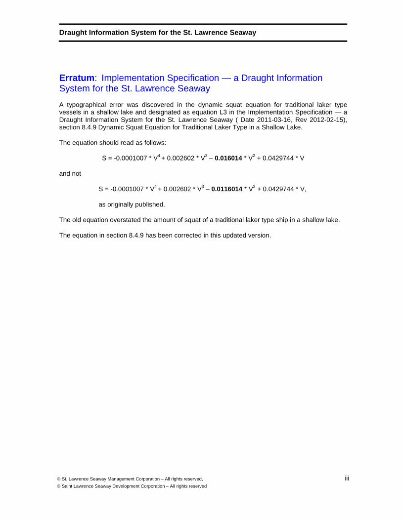
Erratum : Implementation Specification — a Draught Information System for the St. Lawrence Seaway
A typographical error was discovered in the dynamic squat equation for traditional laker type vessels in a shallow lake and designated as equation L3 in the Implementation Specification — a Draught Information System for the St. Lawrence Seaway ( Date 2011-03-16, Rev 2012-02-15), section 8.4.9 Dynamic Squat Equation for Traditional Laker Type in a Shallow Lake.
The equation should read as follows:
S = -0.0001007 * V4 + 0.002602 * V3 – 0.016014 * V2 + 0.0429744 * V
and not
S = -0.0001007 * V4 + 0.002602 * V3 – 0.0116014 * V2 + 0.0429744 * V,
as originally published.
The old equation overstated the amount of squat of a traditional laker type ship in a shallow lake.
The equation in section 8.4.9 has been corrected in this updated version.
Draught Information System for the St. Lawrence Sea way
iv
© St. Lawrence Seaway Management Corporation – All rights reserved,
© Saint Lawrence Seaway Development Corporation – All rights reserved
Contents Page
1 Scope 9
2 Conformance 9
3 Normative References 9
4 Terms and Definitions 10
5 Symbols and abbreviations 13
5.1 Symbols 13
5.2 Abbreviated Terms 14
5.3 Numerical Values 14
5.4 Format for Latitude and Longitude 15
6 Background (informative) 15
7 Data Specifications 16
7.1 Overview of Data Specification 16
7.2 Hydrographic Data Requirements 16
7.2.1 Hydrographic Data 16
7.2.2 Bathymetry Data 17
7.2.3 Chart and High Resolution Bathymetry Updates 17
7.3 Water Level Data Requirements 18
7.3.1 AIS Information 18
7.3.2 Water Level Calculation 18
7.3.3 Interpolation Capability 18
8 UKC (Under Keel Clearance) Calculation Requirements 18
8.1 Overview of UKC Requirements 18
8.2 Channel Type 18
8.3 Ship Type 19
8.4 Squat Formula 21
8.4.1 Squat Equation Conditions 21
8.4.2 Dynamic Squat Equation for All Ship Types in a Cana l 21
8.4.3 Dynamic Squat Equation for Traditional Laker Type i n a Canal 22
8.4.4 Dynamic Squat Equation for Chemical Tanker Type in a Canal 22
8.4.5 Dynamic Squat Equation for Oceangoing Laker Type in a Canal 22
8.4.6 Dynamic Squat Equation for Oceangoing Bulk Carrier Type in a Canal 22
8.4.7 Dynamic Squat Equation for All Ship Types in a Lake 23
8.4.8 Dynamic Squat Equation for New Laker Type in a Shal low Lake 23
8.4.9 Dynamic Squat Equation for Traditional Laker Type i n a Shallow Lake 23
8.4.10 Dynamic Squat Equation for Oceangoing Laker Type in a Shallow Lake 23
8.5 Vessel Meets 24
8.6 Look-ahead Feature 24
9 Operational Specifications 25
9.1 Display Requirement 25
9.2 Recording Requirement 26
9.3 Customization Requirement 26
9.4 General Requirement 26
Draught Information System for the St. Lawrence Sea way
© St. Lawrence Seaway Management Corporation – All rights reserved,
© Saint Lawrence Seaway Development Corporation – All rights reserved v
Annex A (normative) Conformance and Testing 27
A.1 Overview 27
A.1.1 Introduction 27
A.1.2 Test Conditions 27
A.2 Conformance Tests 28
A.2.1 Conformance to Read and Process S-57 Format ENC Dat a 28
A.2.2 Conformance to Read and Process High Resolution Con tour Bathymetry Data 29
A.2.3 Conformance to Maintain a Log of Updates 30
A.2.4 Conformance to Read and Process AIS Information 31
A.2.5 Conformance to Manage Water Level Requirements 31
A.2.6 Conformance to Determine Channel Type 32
A.2.7 Conformance to Squat Equation Conditions 33
A.2.8 Conformance to Determine Vessel Meet Condition 34
A.2.9 Conformance to Determine Look-ahead Feature 35
A.2.10 Conformance to Verify Display Requirements 35
A.2.11 Conformance to Verify Recording Requirements 37
A.2.12 Conformance to Verify General Requirements 37
Annex B (normative) Recording Requirements 39
B.1 Overview 39
B.1.1 Introduction 39
B.1.2 Values to be Reproduced at Time of Playback 39
B.1.3 Records to be Held Onboard of the Vessel 40
Annex C (normative) Draught Information Parameters Specific to the St. Lawrence Seaway 41
C.1 Introduction 41
C.2 Minimum Under Keel Clearance 41
C.3 High Resolution Bathymetry 41
C.4 Water Level Datum 41
C.5 Water Level Interpolation 41
C.6 Channel Type 44
Annex D (normative) Current Speed Approximations 46
D.1 Introduction 46
D.2 Current Tables 46
Annex E (normative) Alarms and Alerts 49
E.1 Alarm and Alert Environment 49
E.2 Alarm and Alert Conditions 49
Annex F (informative) Examples 51
F.1 Introduction 51
F.2 Example of High Resolution Bathymetry 51
F.3 Example Showing a Perspective View 52
F.4 Example of Operation Showing Areas Where UKC is Les s Than Specified 53
F.5 System Example 1 54
F.6 System Example 2 55
Bibliography 56
Draught Information System for the St. Lawrence Sea way
vi
© St. Lawrence Seaway Management Corporation – All rights reserved,
© Saint Lawrence Seaway Development Corporation – All rights reserved
Foreword
This document is an industrial Implementation Specification developed under the guidance of the St. Lawrence Seaway Management Corporation and the Saint Lawrence Seaway Development Corporation, together with representatives from system manufacturers and the shipping industry. The purpose is to increase the safety of navigation in the St. Lawrence Seaway by increasing the knowledge about the under keel clearance of vessels transiting the Seaway.
This document describes an important component of any "e-Navigation" system, and the contents of this document may be applied to other areas than the St. Lawrence Seaway. If this is done, it is necessary that the specification be further developed to ensure that it is fully applicable in other situations.
This document has also been drafted in general accordance with the ISO/IEC Directives, Part 2, "Rules for the structure and drafting of International Standards". This is to permit the document to be in the appropriate form so that it could be submitted as an input toward the development of a National Standard of The United States of America and / or Canada at some time in the future.
Attention is drawn to the possibility that some of the elements of this document may be the subject of patent rights. The St. Lawrence Seaway Management Corporation and the Saint Lawrence Seaway Development Corporation shall not be held responsible for identifying any or all such patent rights.
In accordance with the "Guidelines for the Implementation of the Common Patent Policy for ITU-T/ITU-R/ISO/IEC (March 2007)" [8] patented items are restricted for inclusion in a standard unless the use of the patented item is justifiable for technical reasons and the rights holder agrees to negotiate licences with interested applicants, wherever located, on reasonable terms and conditions. No patent rights have been identified by any of the parties involved in the development or review of this standard.
Draught Information System for the St. Lawrence Sea way
© St. Lawrence Seaway Management Corporation – All rights reserved,
© Saint Lawrence Seaway Development Corporation – All rights reserved vii
Introduction
This document describes a Draught Information System which is a necessary component required for developing "e-Navigation" that will increase the safety of navigation in the St. Lawrence Seaway by providing the mariner with better information about under keel clearance. The primary purpose is to ensure that a safe under keel clearance is maintained by vessels as they make maximum use of the available water column. Use of this system is not a mandatory requirement for transiting the Seaway at or at less than the published maximum draught.
This document is an industrial Implementation Specification developed under the guidance of the St. Lawrence Seaway Management Corporation and the Saint Lawrence Seaway Development Corporation, together with representatives from system manufacturers and the shipping industry. The development of this specification has followed accelerated procedures derived from the ISO standardization process that endeavours to develop a broad based consensus standard. This will allow for future formal standardization, if required through the national public standardization processes in Canada and the United States.
Shipping on the Seaway is limited by the draught and size of the ships that can transit the canals and locks. The usable dimensions of the locks are 233.5 m (766 ft)1 long, 24.4 m (80 ft) wide with a minimum depth of water of 9.1 m (30 ft) over the sill of the lock. The minimum depth of water at chart datum in the channel is 8.2 m (27 ft). These dimensions define the maximum size of vessels, a limit known as "Seaway-Max". The Seaway specified draught applies from Montreal through the seven lower locks and the eight locks of the Welland Canal. Some ocean-going vessels go through the locks partially loaded to accommodate the limitations.
The International Hydrographic Organization (IHO) has developed a set of international standards for electronic navigation. The current standard for the Electronic Nautical Chart (ENC) is IHO S-57. National Hydrographic Offices in many nations including Canada and the USA produce ENCs in conformance with this standard. Systems to process this data for navigation are called Electronic Chart Display Information Systems (ECDIS). ECDIS equipment has been approved for use in ocean going vessels by the International Maritime Organization (IMO).
The ECDIS specifications were never meant for navigation in controlled waterways. Additional information is required for vessels to be able to transit locks, canals, narrow channels and shallow lakes. When additional layers of information are displayed overlaid on an ENC the information could add to the screen clutter. The Draught Information System is an aid to navigation and is not IMO ECDIS compliant because of the additional layers of information that may obscure other EDCIS required information; however, it may operate with an ECDIS. The Draught Information System is a valuable aid to navigation because it allows for the display of the predicted under keel clearance ahead of the vessel.
The S-57 spatial data standard and the ENC product specification were bundled into one document, and as a result the specification became frozen to facilitate stability. However, this also stifled innovation. Recently the IHO separated the two concepts allowing the product specification to remain stable and allowing the structural part of the standard to be enhanced. In January of 2010, it published S-100 which is a general architecture standard for electronic hydrographic 1 This distance (766 ft) represents the usable length of the lock at the Canadian locks between the lower end ship arrestor and the inside face of the breast wall.
Draught Information System for the St. Lawrence Sea way
viii
© St. Lawrence Seaway Management Corporation – All rights reserved,
© Saint Lawrence Seaway Development Corporation – All rights reserved
products including Electronic Nautical Charts. The ENC Product Specification is now being put in the document S-101. The product specification may remain stable, but new capabilities can be added in compliance with the general S-100 Standard. The S-100 suite of standards also contains the addition of Auxiliary Layers (S10x) and electronic high resolution Bathymetry (S-102). These new standards under development will, in the future, allow for the display of auxiliary layers of information on top of an ENC to provide additional aids to navigation. In the future these new standards may facilitate the provision of data for a Draught Information System, but are not applicable to the current system described in this document.
Knowledge of the under keel clearance ahead of a vessel transiting the Seaway is of significant importance to maintaining safety and avoidance of the grounding of vessels, which is of immediate concern to ship traffic in the St. Lawrence Seaway. This document addresses the particular need for information about the predicted under keel clearance ahead of the vessel.
WD Draught Optimization System for the St. Lawrence Seaway
9 © St. Lawrence Seaway Management Corporation – All rights reserved,
© Saint Lawrence Seaway Development Corporation – All rights reserved
Implementation Specification — a Draught Informatio n System for the St. Lawrence Seaway
1 Scope
This Implementation Specification describes the functionality and interfaces to a system which utilizes water level, channel type and bathymetry, and vessel characteristics, speed and dynamics to determine current and predicted under keel clearance to promote safe navigation and maximize the use of the water column. This specification also defines the information content for each of the bathymetry and water level input data sets. It includes a set of squat formulas for different vessel types and channel configurations. These may be extended by the addition of supplementary information to the specification.
This Implementation Specification does not specify the detailed presentation and detailed user interface to systems that display or otherwise use this information. It does specify the general functionality of what type of warning and alarms need to be provided to a user. The use of the Draught Information System is not a mandatory requirement for transiting the Seaway at, or at less than the published maximum draught.
2 Conformance
This Implementation Specification specifies 12 conformance classes. Any system claiming conformance to this Implementation Specification shall satisfy the requirements as described in Annex A.
Use of this specification to develop a system to be used as an aid to navigation requires that the conformance of the system to the Implementation Specification be demonstrated by showing how the system complies with the applicable conformance clauses. The conformance tests described in Annex A may be used by an independent third party to verify compliance. They may also be used by a customer purchasing a system as a procurement requirement, and by a system developer for self testing as part of development.
3 Normative References
The following referenced documents are indispensable for the application of this document. For dated references, only the edition cited applies. For undated references, the latest edition of the referenced document (including any amendments) applies.
3.1 IHO S-57, Transfer Standard for Digital Hydrographic Data, Edition 3.1.1, January 2007, Monaco.
3.2 IHO S-52, Specifications for Chart Content and Display Aspects of ECDIS, Edition 6.0, March 2010, Monaco
Draught Information System for the St. Lawrence Sea way
10 © St. Lawrence Seaway Management Corporation – All rights reserved,
© Saint Lawrence Seaway Development Corporation – All rights reserved
3.3 IEC 60945:2002, Maritime navigation and radio communication equipment and systems - General requirements – Methods of testing and required test results, International Electrotechnical Commission, Geneva, Switzerland.
3.4 St. Lawrence Seaway AIS Data Messaging Formats and Specifications, Revision 4.1, 9 April 2010, US Department of Transportation, John A Volpe Transportation System Centre, Cambridge MA, USA.
Note: This is in compliance with ITU-R M.1371 message format.
4 Terms and Definitions
For the purposes of this Implementation Specification, the terms and definitions given in the following apply. These definitions are intended to apply only to this document and are not necessarily generic definitions.
4.1 Channel Type
one of a set of predefined channel types through which a vessel passes. The channel type affects selection of the applicable Squat Formula .
4.2 Bathymetry
determination of river and lake depths. The general configuration of river and/or lake bottom as determined by profile analysis of depth data.
[ adapted from the IHO Hydrographic Dictionary S-32, Fifth Edition, Monaco, 1994 ]
4.3 Bathymetric Map
topographic map of the river bottom or the bed of a lake; topographic chart of the bed of a body of water, or a part of it. Generally, bathymetric maps show depths by contour lines and gradient tints.
4.4 Controlled Waterway
navigable waterway including locks, canals, narrow channels or shallow lakes where the rules for navigation are managed by an authority.
4.5 Draught
depth to which a vessel is immersed when bearing a given load, (US - draft)
[ The Random House College Dictionary, Revised Edition ]

Draught Information System for the St. Lawrence Sea way
© St.Lawrence Seaway Management Corporation – All rights reserved © Saint Lawrence Seaway Development Corporation – All rights reserved
11
4.6 High Resolution Bathymetry
bathymetry data of at least 10 cm vertical interval supplied as contour line chart data in S-57 format.
For St. Lawrence Seaway specific specifications see Annex C3.
4.7 International Nautical Mile
unit of length equal to 1,852 Meters . This value was approved by the International Hydrographic Conference of 1929 and has been adopted by nearly all maritime states.
[ IHO Hydrographic Dictionary S-32, Fifth Edition, Monaco, 1994 ]
4.8 Knot
nautical unit of speed. One knot is one Nautical Mile per Hour.
[ IHO Hydrographic Dictionary S-32, Fifth Edition, Monaco, 1994 ]
One knot equals 1852 meters per hour (m/h)
4.9 Nautical Mile
unit of length used principally in navigation. See International Nautical Mile.
[ IHO Hydrographic Dictionary S-32, Fifth Edition, Monaco, 1994 ]
4.10 Metre
basic unit of length in the SI System. (US - meter)
[ IHO Hydrographic Dictionary S-32, Fifth Edition, Monaco, 1994 ]
Note the SI System is defined by the international standard ISO 80000-3 [2] and by the Bureau International de Poids et Mesures [3]
4.11 Reach
waterway between two adjacent locks within a canal system.
4.12 Look-ahead Zone
zone starting at the Ship's Own Position covering the width of the navigational channel ahead of a vessel , the length of which must be sufficient to bring the vessel to a full stop before the end of the zone is reached. The minimum length of the Look-ahead Zone is defined as the distance the
Draught Information System for the St. Lawrence Sea way
12 © St. Lawrence Seaway Management Corporation – All rights reserved,
© Saint Lawrence Seaway Development Corporation – All rights reserved
ship can travel in 6 minutes at its current speed. The zone must include all the high resolution bathymetry data available starting from Ship's Own Position , follow the path of the channel and cover at least the full length of the Look-ahead Zone.
Note: If the vessel requires more than the minimum length of the Look-ahead Zone as defined above to come to a complete stop, the look-ahead zone must be set to that greater distance.
4.13 Seaway < St. Lawrence Seaway >
deep waterway between the Port of Montreal and Lake Erie and includes all locks, canals and connecting and contiguous waters that are part of the deep waterway, and all other canals and works, wherever located, the management, administration and control of which have been entrusted to the St. Lawrence Seaway Management Corporation or the Saint Lawrence Seaway Development Corporation.
[ adapted from the "Seaway Handbook", 2010 Edition ]
4.14 Ship's Own Position
position of a vessel defined by the conning position on the vessel .
Note: The ships own position reference point is the conning position of the ship. The dimensions of the ship are defined in terms of the conning position. In addition the position of the GPS antenna (as used in AIS) is described in reference to the conning position.
4.15 Speed Over Ground
speed of a vessel measured with respect to the bottom of the channel.
4.16 Speed Through The Water
speed of a vessel measured with respect to the water in which it is floating. The difference with respect to the Speed Over Ground is the current. The speed of the current is vectorial and for the Seaway, the direction is from the Great Lakes to the sea.
4.17 Ship Type
one of a set of predefined vessel types for which squat formulas are available .
4.18 Squat
effect that causes a vessel moving through water to create an area of lowered pressure under its bottom that increases the effective draught (i.e. lowers the vessel in the water). The effect is a result of Bernoulli's principle of fluid dynamics. The squat represents the increase in effective draught .
Draught Information System for the St. Lawrence Sea way
© St.Lawrence Seaway Management Corporation – All rights reserved © Saint Lawrence Seaway Development Corporation – All rights reserved
13
the increase in a vessel's draught arising from its motion through the water. [ Shorter Oxford English Dictionary 2002 ]
For a ship underway, the change of level of the bow and stern from the still water condition in response to the elevation and depression of the water level about the hull resulting from the bow and stern wave systems.
[ IHO Hydrographic Dictionary S-32, Fifth Edition, Monaco, 1994 ]
4.19 Squat Formula formula to calculate estimated squat based on the ship type , speed of the vessel through water, and the proximity to the sides of the channel. These formulas were developed from on-the-fly measurements/testing. The definitions given in this document are only applicable to specific areas for which they were established. They are not generic squat formulas. For the purpose of navigation in the waters under the jurisdiction of the St. Lawrence Seaway Management Corporation and the Saint Lawrence Seaway Development Corporation, the accepted squat formulas are those contained in the document below:
[ 2002. Morse, Brian; Michaud, Stéphanie and Siles, Jimmy. “Maximization of Ship Draft in the St. Lawrence Seaway; Volume 2: In-Depth Analysis of Squat and UKC”. Université Laval for Transport Development Centre of Transport Canada and The St. Lawrence Seaway Management Corporation. ]
4.20 Under Keel Clearance
distance between the vessel’s deepest point and the known channel bottom. The minimum under keel clearance is also known as the minimum safety factor.
4.21 Vessel
ship or boat, one of larger size; a craft. [ Shorter Oxford English Dictionary 2002 ]
5 Symbols and abbreviations
5.1 Symbols
S Dynamic Squat (expressed in metres)
V Speed Through Water (expressed in Knots)
VG Speed Over Ground (expressed in Knots)
kn Knots (unit of measure of speed)
m Metres (unit of measure of distance from the International System of Units (SI) )
Draught Information System for the St. Lawrence Sea way
14 © St. Lawrence Seaway Management Corporation – All rights reserved,
© Saint Lawrence Seaway Development Corporation – All rights reserved
cm Centimetres (unit of measure of distance from the International System of Units (SI) )
5.2 Abbreviated Terms
AIS Automatic Identification System (see UAIS)
DIS Draught Information System
ENC Electronic Nautical Chart
ECDIS Electronic Chart Display Information Systems
EMI Electro Magnetic Interference
IHO International Hydrographic Organization
IMO International Maritime Organization (UN Organization for Maritime Regulations)
ITU-R International Telecommunications Union - Radio Communications Sector (formerly CCIR)
IUT Implementation Under Test
NAD 27 North American Datum 1927
MMSI Maritime Mobile Service Identity
OAB Overall Breadth of a Vessel (Beam)
OAL Over All Length of a Vessel
SI Système International d'Unités (International System of Units)
SOLAS Safety Of Life At Sea (Sub part of IMO Regulation for ocean going vessels)
UKC Under Keel Clearance
UAIS Universal Automatic Identification System
5.3 Numerical Values
All physical values have associated with them an accuracy of measurement. For example, a distance of 1 metre has associated with it an accuracy of plus or minus the accuracy by which that 1 metre distance can be measured.
In this specification all numerical values have been biased toward enhanced safety of navigation. That is, the numerical value is taken at the limit plus or minus the accuracy value that provides the highest safety margin.
Draught Information System for the St. Lawrence Sea way
© St.Lawrence Seaway Management Corporation – All rights reserved © Saint Lawrence Seaway Development Corporation – All rights reserved
15
The data values are given as single numbers without an accuracy statement because they are already biased for safety and should be taken as absolute values. This is true for all data including the bathymetry and water levels.
Note: Point data representing depth measurements is shallow biased. Bathymetric data is captured as actual depth data with no bias. This data is then processed by the Hydrographic Office from gridded to contour bathymetry using a generalization that is biased towards safety.
5.4 Format for Latitude and Longitude
The format for the specification of Latitude and Longitude is in conformance with IEC 61162-2 [11] and NEMA 0183 [12] . Latitude and Longitude are specified in degrees, minutes and decimal fractions of minutes to 4 digits of accuracy with leading or trailing zeros as needed and with a flag indicating North or South, or East or West.
For Latitude: DD MM.MMMM N/S. For Longitude: DDD MM.MMMM E/W
where "D" represents the digits describing degrees, "M" represents the digits describing minutes or decimal fractions of a minute, and "N" , "S", "E", or "W" is a flag representing North, South, East or West respectively.
6 Background (informative)
The primary purpose of the Draught Information System is to increase the safety of navigation by providing the mariner with additional information about the under keel clearance. The ship dynamics combined with bathymetry and water level information allow for a dynamic portrayal of the clearance between the bottom of the vessel and the bottom of the channel. This also provides a look-ahead capability that will assist in safe navigation. The mariner must maintain a minimum safe under keel clearance, but has better information about the vessel’s under keel clearance and therefore may navigate more safely, while making maximum use of the water column.
Organizations have different responsibilities in providing the various aspects of e-navigation. The bathymetric depth is the responsibility of the Hydrographic Office; in the case of Canada and the USA it is the Canadian Hydrographic Service, and the US NOAA Coast and Geodetic Survey, respectively. In addition in the US the US Army Corps of Engineers is an official supplier of bathymetric depth data for some waterways. The measurement of the real time water levels can come from several sources. The condition of the vessel is, of course, the responsibility of the shipping company and in particular the ship's master. However, there needs to be standards in place for all aspects of the system representing best industry practices.
The IHO is currently working on a replacement standard for S-57 that will include a general standard for all types of hydrographic data called S-100, and specific product specifications for ENC data and for other layers of associated information. The standard for a bathymetric data product specification will be S-102. The IHO has agreed in 2009 to also develop a standard (presently called S-10x) which will address the addition of auxiliary layers of information that may be displayed as layers over S-100 based chart data. One of the potential layers under study is a
Draught Information System for the St. Lawrence Sea way
16 © St. Lawrence Seaway Management Corporation – All rights reserved,
© Saint Lawrence Seaway Development Corporation – All rights reserved
coverage2 layer describing currents. The S-100 format has been adopted by IHO but the S-101 ENC format and other related standards are in development. The Draught Information System specification does NOT address S-100 or S-10x based data formats. That is, in the future there will be an international standard for the high resolution bathymetry data component of a system for draught information. However there are no international standards under development that relate that information to the ship's dynamics and allow one to determine under keel clearance.
Predicting the behaviour of a vessel and knowing its under keel clearance requires that there be a standard practise relating the water level, bathymetric bottom depth and ship dynamics. This standard practice needs to be consistent across all providers of Draught Information System equipment so that users of this auxiliary aid to navigation will not need special training for each different system implementation.
The overall objective of this Implementation Specification is to develop a specification for a "Draught Information System". This specification is a standard that specifies how the under keel clearance of a vessel can be calculated by considering water level, bathymetric bottom depth and ship dynamics. This is an essential calculation to ensure safety. The initial details of the ship dynamics component have been derived from the experimental implementation done by the St. Lawrence Seaway in conjunction with two system manufacturers and two shipping companies. This specification describes best industry practices.
7 Data Specifications
7.1 Overview of Data Specification
This clause defines the data requirements needed to support the Draught Information System. Four types of data are required: vessel dynamics (Squat curves), together with S-57 ENC data, high resolution bathymetry data and water level data. Input data shall be used to calculate an UKC value to the nearest 1 cm.
S-57 ENC data is used as a background on a Draught Information System. The system is therefore not an ECDIS because the additional high resolution bathymetry data and the display of danger zones where there is insufficient under keel clearance for navigation would clutter the display. Even if a system has been certified as an ECDIS, it does not operate as an ECDIS if additional information beyond the S-57 ENC product specification is displayed. However, a Draught Information System is complementary to an ECDIS and may be used in conjunction with an ECDIS.
7.2 Hydrographic Data Requirements
7.2.1 Hydrographic Data
The Draught Information System shall be able to read and process S-57 format ENC data. The system shall be capable of reading all of the features available in the ENC product specification and displaying all of the features at the base display level. The format for the input of data shall be S-57. The detailed specification for S-57 data is the "IHO Transfer Standard for Digital Hydrographic Data, Edition 3.1.1", given in Clause 3.1 of this document. The base display level is
2 Coverages are a method of description of geographic areas involving surfaces and are described in ISO 19123 Geographic Information - Coverage Geometry and Functions. [10]
Draught Information System for the St. Lawrence Sea way
© St.Lawrence Seaway Management Corporation – All rights reserved © Saint Lawrence Seaway Development Corporation – All rights reserved
17
defined in IHO S-52 "Specifications for Chart Content and Display Aspects of ECDIS, Edition 6.0 [5] . S-52 pattern fills3 are exempted from the base display. S-52 specifies the Shallow, Safety and Deep contour lines, and the DIS system should represent those lines in accordance with S-52.
7.2.2 Bathymetry Data
The Draught Information System shall be able to read S-57 formatted, high resolution contour bathymetry data consisting of a subset of the S-57 ENC specification including additional high resolution S-57 feature objects as specified by the Hydrographic Office (HO) as an additional layer of data to be displayed on top of the display of ENC data.
This high resolution bathymetry data consists of a set of contour data with a close contour spacing. The data consists of the following S-57 object types:
DEPCNT (Depth Contour);
DEPARE (Depth Area);
SOUNDG (Sounding Data);
MCOVR (Coverage and Extent)
All depth contours shall be closed curves, or intersect the boundaries of the data cell so that they are logically closed by the data cell boundary.
For St. Lawrence Seaway specific specifications see Annex C.3.
Note: An additional input format for future consideration is S-100 data. The S-100 format has been adopted by IHO but the S-102 High Resolution Bathymetry format has not yet been finalized (as per the date of publication of this document) so this is a future capability that is not included in this specification.
7.2.3 Chart and High Resolution Bathymetry Updates
The Draught Information System shall be using the most current S-57 ENC charts commercially available and the most current high resolution bathymetry data when a vessel is transiting the waters of the St. Lawrence Seaway Management Corporation and of the Saint Lawrence Seaway Development Corporation (Seaways). Vessels are to maintain a log of updates and to have a file showing all files being used as well as their version. The update policy for data sets in the St. Lawrence Seaway controlled waterway is the replacement of data sets.
Note: The cells provided by the CHS are 0.02 x 0.02 degrees, and the name of the cell is the south west corner position in decimal degrees. For example 44827532; that is, a cell at 44.82N 75.32W south-west corner of the cell. A formal cell naming convention is required that includes the HO of origin, the scale, the version and the cell ID.
3 The display of areas in the base display level of S-57 data on a DIS is not required to have pattern fills since the high resolution bathymetric data will overlay such filled patterns in the areas of interest for the DIS.

Draught Information System for the St. Lawrence Sea way
18 © St. Lawrence Seaway Management Corporation – All rights reserved,
© Saint Lawrence Seaway Development Corporation – All rights reserved
7.3 Water Level Data Requirements
7.3.1 AIS Information
The Draught Information System shall be able to read and process an AIS "broadcast" binary message number 8, containing the Seaway AIS "Water Level" message number 3. This message is defined in normative reference 3.2. This provides an adjusted conservative water level at a given location in reference to the datum as specified in the water level message. The water level information will be processed as frequently as the information is available via AIS messages. Note: This will typically be from every 2 to 10 minutes. If the AIS system transmits an estimated water value this should be recognized and identified to the mariner.
For the St. Lawrence Seaway specific specifications see Annex C.4.
7.3.2 Water Level Calculation
The Draught Information System shall be able to calculate the accurate water level offset from chart datum at the station position with respect to the reference hydrographic datum (e.g. IGLD-85). That is, the calculation shall produce the water level offset above or below chart datum, where the AIS water level is transmitted with reference to the hydrographic datum (not the chart datum). This requires the knowledge of the chart datum at each water level station. Water level values and offsets are in meters to two (2) decimal places.
7.3.3 Interpolation Capability
The Draught Information System shall be able to calculate the accurate water level offset from chart datum at Ship's Own Position based on a linear interpolation between the gauge ahead and the gauge behind the vessel, in meters to two (2) decimal places as provided through AIS. If there is only one value available such as in a reach (for example the Beauharnois pool), then there is no interpolation required.
For the St. Lawrence Seaway specific specifications see Annex C.5.
8 UKC (Under Keel Clearance) Calculation Requiremen ts
8.1 Overview of UKC Requirements
The Under Keel Clearance is calculated based on an estimated vessel squat, the vessel’s draught, the known elevation of the channel bottom and the water level at the ship’s position. Squat varies as a function of the vessel’s speed through water, the hull configuration represented by ship type and the channel type. Within the Seaway two channel types have been defined and squat equations have been defined for each type of channel, per vessel type.
8.2 Channel Type
The effective increase in draught (i.e. increase in squat which lowers the vessel in the water) depends on the fluid dynamics of the water the vessel is passing through. The effect is different in a semi-open water channel (shallow lake) where the effect is predominantly between the vessel and the bottom or in a canal where there may be an additional interaction with the sides of the canal which may come into play.
Draught Information System for the St. Lawrence Sea way
© St.Lawrence Seaway Management Corporation – All rights reserved © Saint Lawrence Seaway Development Corporation – All rights reserved
19
The Draught Information System shall be able to select the appropriate Squat Formula for the Channel Type through which the vessel is passing. This information shall be provided for each location.
For the St. Lawrence Seaway specific specifications see Annex C.6.
8.3 Ship Type
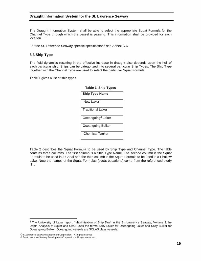
The fluid dynamics resulting in the effective increase in draught also depends upon the hull of each particular ship. Ships can be categorized into several particular Ship Types. The Ship Type together with the Channel Type are used to select the particular Squat Formula.
Table 1 gives a list of ship types.
Table 1–Ship Types
Ship Type Name
New Laker
Traditional Laker
Oceangoing4 Laker
Oceangoing Bulker
Chemical Tanker
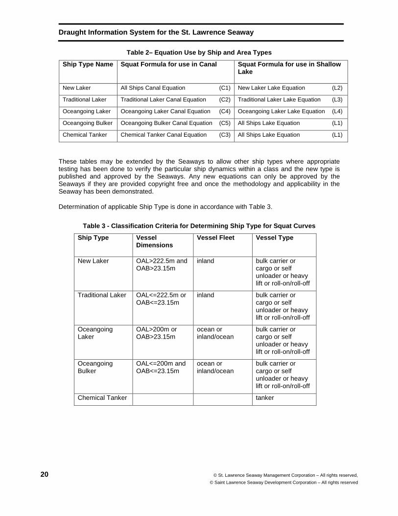
Table 2 describes the Squat Formula to be used by Ship Type and Channel Type. The table contains three columns. The first column is a Ship Type Name. The second column is the Squat Formula to be used in a Canal and the third column is the Squat Formula to be used in a Shallow Lake. Note the names of the Squat Formulas (squat equations) come from the referenced study [1] .
4 The University of Laval report, “Maximization of Ship Draft in the St. Lawrence Seaway; Volume 2: In-Depth Analysis of Squat and UKC” uses the terms Salty Laker for Oceangoing Laker and Salty Bulker for Oceangoing Bulker. Oceangoing vessels are SOLAS class vessels.
Draught Information System for the St. Lawrence Sea way
20 © St. Lawrence Seaway Management Corporation – All rights reserved,
© Saint Lawrence Seaway Development Corporation – All rights reserved
Table 2– Equation Use by Ship and Area Types
Ship Type Name Squat Formula for use in Canal Squat Formula for use in Shallow Lake
New Laker All Ships Canal Equation (C1) New Laker Lake Equation (L2)
Traditional Laker Traditional Laker Canal Equation (C2) Traditional Laker Lake Equation (L3)
Oceangoing Laker Oceangoing Laker Canal Equation (C4) Oceangoing Laker Lake Equation (L4)
Oceangoing Bulker Oceangoing Bulker Canal Equation (C5) All Ships Lake Equation (L1)
Chemical Tanker Chemical Tanker Canal Equation (C3) All Ships Lake Equation (L1)
These tables may be extended by the Seaways to allow other ship types where appropriate testing has been done to verify the particular ship dynamics within a class and the new type is published and approved by the Seaways. Any new equations can only be approved by the Seaways if they are provided copyright free and once the methodology and applicability in the Seaway has been demonstrated.
Determination of applicable Ship Type is done in accordance with Table 3.
Table 3 - Classification Criteria for Determining S hip Type for Squat Curves
Ship Type Vessel Dimensions
Vessel Fleet Vessel Type
New Laker OAL>222.5m and OAB>23.15m
inland bulk carrier or cargo or self unloader or heavy lift or roll-on/roll-off
Traditional Laker OAL<=222.5m or OAB<=23.15m
inland bulk carrier or cargo or self unloader or heavy lift or roll-on/roll-off
Oceangoing Laker
OAL>200m or OAB>23.15m
ocean or inland/ocean
bulk carrier or cargo or self unloader or heavy lift or roll-on/roll-off
Oceangoing Bulker
OAL<=200m and OAB<=23.15m
ocean or inland/ocean
bulk carrier or cargo or self unloader or heavy lift or roll-on/roll-off
Chemical Tanker tanker
Draught Information System for the St. Lawrence Sea way
© St.Lawrence Seaway Management Corporation – All rights reserved © Saint Lawrence Seaway Development Corporation – All rights reserved
21
8.4 Squat Formula
8.4.1 Squat Equation Conditions
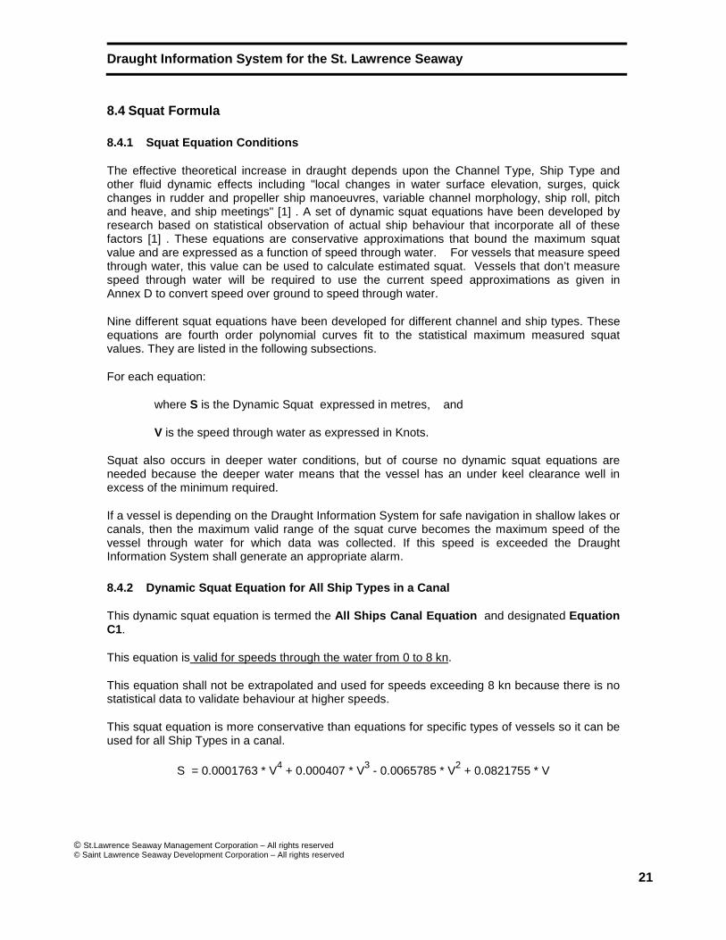
The effective theoretical increase in draught depends upon the Channel Type, Ship Type and other fluid dynamic effects including "local changes in water surface elevation, surges, quick changes in rudder and propeller ship manoeuvres, variable channel morphology, ship roll, pitch and heave, and ship meetings" [1] . A set of dynamic squat equations have been developed by research based on statistical observation of actual ship behaviour that incorporate all of these factors [1] . These equations are conservative approximations that bound the maximum squat value and are expressed as a function of speed through water. For vessels that measure speed through water, this value can be used to calculate estimated squat. Vessels that don’t measure speed through water will be required to use the current speed approximations as given in Annex D to convert speed over ground to speed through water.
Nine different squat equations have been developed for different channel and ship types. These equations are fourth order polynomial curves fit to the statistical maximum measured squat values. They are listed in the following subsections.
For each equation:
where S is the Dynamic Squat expressed in metres, and
V is the speed through water as expressed in Knots.
Squat also occurs in deeper water conditions, but of course no dynamic squat equations are needed because the deeper water means that the vessel has an under keel clearance well in excess of the minimum required.
If a vessel is depending on the Draught Information System for safe navigation in shallow lakes or canals, then the maximum valid range of the squat curve becomes the maximum speed of the vessel through water for which data was collected. If this speed is exceeded the Draught Information System shall generate an appropriate alarm.
8.4.2 Dynamic Squat Equation for All Ship Types in a Canal
This dynamic squat equation is termed the All Ships Canal Equation and designated Equation C1.
This equation is valid for speeds through the water from 0 to 8 kn.
This equation shall not be extrapolated and used for speeds exceeding 8 kn because there is no statistical data to validate behaviour at higher speeds.
This squat equation is more conservative than equations for specific types of vessels so it can be used for all Ship Types in a canal.
S = 0.0001763 * V4 + 0.000407 * V3 - 0.0065785 * V2 + 0.0821755 * V
Draught Information System for the St. Lawrence Sea way
22 © St. Lawrence Seaway Management Corporation – All rights reserved,
© Saint Lawrence Seaway Development Corporation – All rights reserved
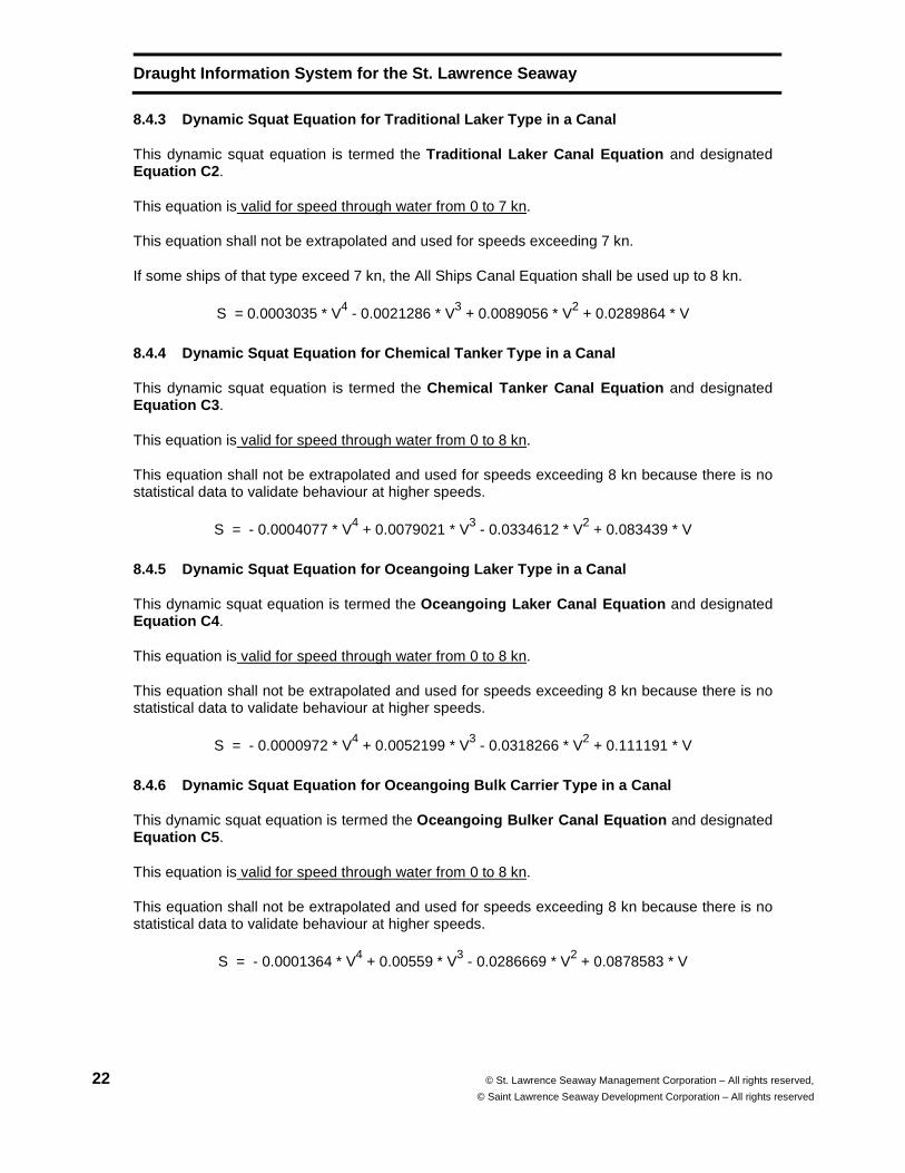
8.4.3 Dynamic Squat Equation for Traditional Laker Type in a Canal
This dynamic squat equation is termed the Traditional Laker Canal Equation and designated Equation C2 .
This equation is valid for speed through water from 0 to 7 kn.
This equation shall not be extrapolated and used for speeds exceeding 7 kn.
If some ships of that type exceed 7 kn, the All Ships Canal Equation shall be used up to 8 kn.
S = 0.0003035 * V4 - 0.0021286 * V3 + 0.0089056 * V2 + 0.0289864 * V
8.4.4 Dynamic Squat Equation for Chemical Tanker Ty pe in a Canal
This dynamic squat equation is termed the Chemical Tanker Canal Equation and designated Equation C3 .
This equation is valid for speed through water from 0 to 8 kn.
This equation shall not be extrapolated and used for speeds exceeding 8 kn because there is no statistical data to validate behaviour at higher speeds.
S = - 0.0004077 * V4 + 0.0079021 * V3 - 0.0334612 * V2 + 0.083439 * V
8.4.5 Dynamic Squat Equation for Oceangoing Laker T ype in a Canal
This dynamic squat equation is termed the Oceangoing Laker Canal Equation and designated Equation C4 .
This equation is valid for speed through water from 0 to 8 kn.
This equation shall not be extrapolated and used for speeds exceeding 8 kn because there is no statistical data to validate behaviour at higher speeds.
S = - 0.0000972 * V4 + 0.0052199 * V3 - 0.0318266 * V2 + 0.111191 * V
8.4.6 Dynamic Squat Equation for Oceangoing Bulk Ca rrier Type in a Canal
This dynamic squat equation is termed the Oceangoing Bulker Canal Equation and designated Equation C5 .
This equation is valid for speed through water from 0 to 8 kn.
This equation shall not be extrapolated and used for speeds exceeding 8 kn because there is no statistical data to validate behaviour at higher speeds.
S = - 0.0001364 * V4 + 0.00559 * V3 - 0.0286669 * V2 + 0.0878583 * V
Draught Information System for the St. Lawrence Sea way
© St.Lawrence Seaway Management Corporation – All rights reserved © Saint Lawrence Seaway Development Corporation – All rights reserved
23
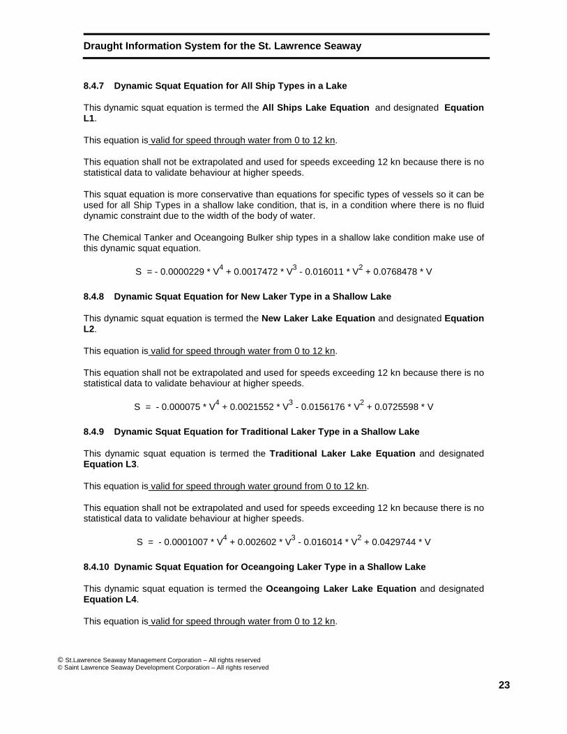
8.4.7 Dynamic Squat Equation for All Ship Types in a Lake
This dynamic squat equation is termed the All Ships Lake Equation and designated Equation L1.
This equation is valid for speed through water from 0 to 12 kn.
This equation shall not be extrapolated and used for speeds exceeding 12 kn because there is no statistical data to validate behaviour at higher speeds.
This squat equation is more conservative than equations for specific types of vessels so it can be used for all Ship Types in a shallow lake condition, that is, in a condition where there is no fluid dynamic constraint due to the width of the body of water.
The Chemical Tanker and Oceangoing Bulker ship types in a shallow lake condition make use of this dynamic squat equation.
S = - 0.0000229 * V4 + 0.0017472 * V3 - 0.016011 * V2 + 0.0768478 * V
8.4.8 Dynamic Squat Equation for New Laker Type in a Shallow Lake
This dynamic squat equation is termed the New Laker Lake Equation and designated Equation L2.
This equation is valid for speed through water from 0 to 12 kn.
This equation shall not be extrapolated and used for speeds exceeding 12 kn because there is no statistical data to validate behaviour at higher speeds.
S = - 0.000075 * V4 + 0.0021552 * V3 - 0.0156176 * V2 + 0.0725598 * V
8.4.9 Dynamic Squat Equation for Traditional Laker Type in a Shallow Lake
This dynamic squat equation is termed the Traditional Laker Lake Equation and designated Equation L3 .
This equation is valid for speed through water ground from 0 to 12 kn.
This equation shall not be extrapolated and used for speeds exceeding 12 kn because there is no statistical data to validate behaviour at higher speeds.
S = - 0.0001007 * V4 + 0.002602 * V3 - 0.016014 * V2 + 0.0429744 * V
8.4.10 Dynamic Squat Equation for Oceangoing Laker Type in a Shallow Lake
This dynamic squat equation is termed the Oceangoing Laker Lake Equation and designated Equation L4 .
This equation is valid for speed through water from 0 to 12 kn.
Draught Information System for the St. Lawrence Sea way
24 © St. Lawrence Seaway Management Corporation – All rights reserved,
© Saint Lawrence Seaway Development Corporation – All rights reserved
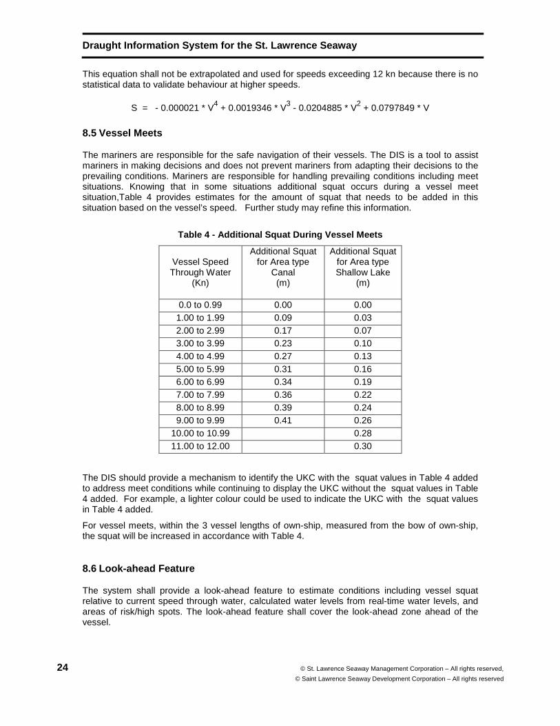
This equation shall not be extrapolated and used for speeds exceeding 12 kn because there is no statistical data to validate behaviour at higher speeds.
S = - 0.000021 * V4 + 0.0019346 * V3 - 0.0204885 * V2 + 0.0797849 * V
8.5 Vessel Meets
The mariners are responsible for the safe navigation of their vessels. The DIS is a tool to assist mariners in making decisions and does not prevent mariners from adapting their decisions to the prevailing conditions. Mariners are responsible for handling prevailing conditions including meet situations. Knowing that in some situations additional squat occurs during a vessel meet situation,Table 4 provides estimates for the amount of squat that needs to be added in this situation based on the vessel’s speed. Further study may refine this information.
Table 4 - Additional Squat During Vessel Meets
Vessel Speed Through Water
(Kn)
Additional Squat for Area type
Canal (m)
Additional Squat for Area type Shallow Lake
(m)
0.0 to 0.99 0.00 0.00 1.00 to 1.99 0.09 0.03 2.00 to 2.99 0.17 0.07 3.00 to 3.99 0.23 0.10 4.00 to 4.99 0.27 0.13 5.00 to 5.99 0.31 0.16 6.00 to 6.99 0.34 0.19 7.00 to 7.99 0.36 0.22 8.00 to 8.99 0.39 0.24 9.00 to 9.99 0.41 0.26
10.00 to 10.99 0.28 11.00 to 12.00 0.30
The DIS should provide a mechanism to identify the UKC with the squat values in Table 4 added to address meet conditions while continuing to display the UKC without the squat values in Table 4 added. For example, a lighter colour could be used to indicate the UKC with the squat values in Table 4 added.
For vessel meets, within the 3 vessel lengths of own-ship, measured from the bow of own-ship, the squat will be increased in accordance with Table 4.
8.6 Look-ahead Feature
The system shall provide a look-ahead feature to estimate conditions including vessel squat relative to current speed through water, calculated water levels from real-time water levels, and areas of risk/high spots. The look-ahead feature shall cover the look-ahead zone ahead of the vessel.
Draught Information System for the St. Lawrence Sea way
© St.Lawrence Seaway Management Corporation – All rights reserved © Saint Lawrence Seaway Development Corporation – All rights reserved
25
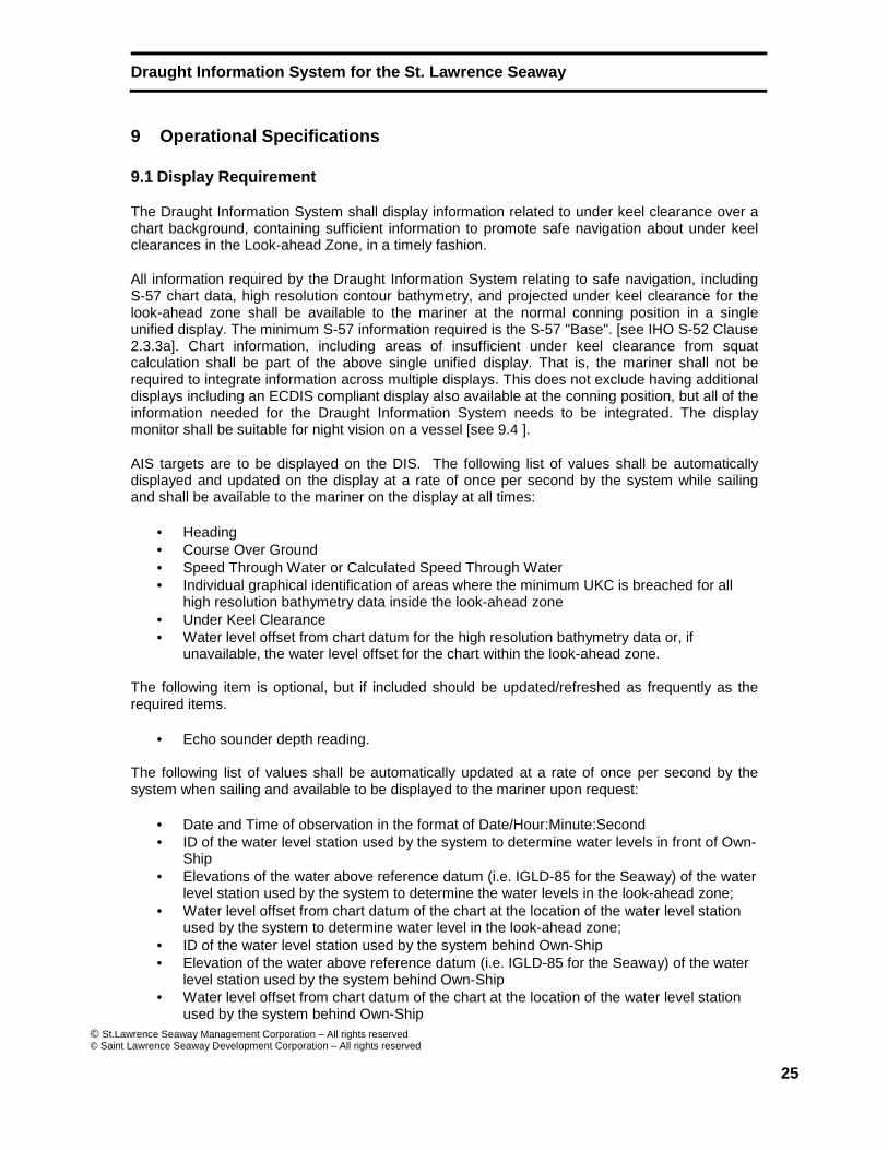
9 Operational Specifications
9.1 Display Requirement
The Draught Information System shall display information related to under keel clearance over a chart background, containing sufficient information to promote safe navigation about under keel clearances in the Look-ahead Zone, in a timely fashion.
All information required by the Draught Information System relating to safe navigation, including S-57 chart data, high resolution contour bathymetry, and projected under keel clearance for the look-ahead zone shall be available to the mariner at the normal conning position in a single unified display. The minimum S-57 information required is the S-57 "Base". [see IHO S-52 Clause 2.3.3a]. Chart information, including areas of insufficient under keel clearance from squat calculation shall be part of the above single unified display. That is, the mariner shall not be required to integrate information across multiple displays. This does not exclude having additional displays including an ECDIS compliant display also available at the conning position, but all of the information needed for the Draught Information System needs to be integrated. The display monitor shall be suitable for night vision on a vessel [see 9.4 ].
AIS targets are to be displayed on the DIS. The following list of values shall be automatically displayed and updated on the display at a rate of once per second by the system while sailing and shall be available to the mariner on the display at all times:
• Heading • Course Over Ground • Speed Through Water or Calculated Speed Through Water • Individual graphical identification of areas where the minimum UKC is breached for all
high resolution bathymetry data inside the look-ahead zone • Under Keel Clearance • Water level offset from chart datum for the high resolution bathymetry data or, if
unavailable, the water level offset for the chart within the look-ahead zone.
The following item is optional, but if included should be updated/refreshed as frequently as the required items.
• Echo sounder depth reading.
The following list of values shall be automatically updated at a rate of once per second by the system when sailing and available to be displayed to the mariner upon request:
• Date and Time of observation in the format of Date/Hour:Minute:Second • ID of the water level station used by the system to determine water levels in front of Own-
Ship • Elevations of the water above reference datum (i.e. IGLD-85 for the Seaway) of the water
level station used by the system to determine the water levels in the look-ahead zone; • Water level offset from chart datum of the chart at the location of the water level station
used by the system to determine water level in the look-ahead zone; • ID of the water level station used by the system behind Own-Ship • Elevation of the water above reference datum (i.e. IGLD-85 for the Seaway) of the water
level station used by the system behind Own-Ship • Water level offset from chart datum of the chart at the location of the water level station
used by the system behind Own-Ship
Draught Information System for the St. Lawrence Sea way
26 © St. Lawrence Seaway Management Corporation – All rights reserved,
© Saint Lawrence Seaway Development Corporation – All rights reserved
• Elevation of the water above reference datum (i.e. IGLD-85 for the Seaway) at Own-Ship • Water level offset from chart datum of the chart at the location of Own-Ship • Individual identification of areas where the minimum UKC is breached • Ship type of Own-Ship. (from list of types in Table 1) • Channel type as used by the squat formulas
o Canal o Shallow Lake
• Indication if a manual water level offset is applied.
Note: A manual water level offset allows an operator to manually enter water levels as a backup situation when water level information acquisition fails. This needs to be recorded in the log file and indicated on the display.
9.2 Recording Requirement
System shall be capable of storing and displaying transit information as specified in Annex B.
9.3 Customization Requirement
This value to be set by the mariner before the voyage commences:
• Draught of Own-Ship (resolution 0.01 metre)
These fixed values to be set by the installer of the system:
• Ship Type of Own-Ship (from list of types in Table 1) • Seaway Safety Factor (resolution 0.01 metre) set to 30 cm (approximately 1 foot)
The values of the water level are normally received by AIS message but may be set manually if accurate water level data is not available.
A mechanism shall be provided to allow the system to be reset to default DIS mode.
9.4 General Requirement
The computing hardware that is used to support the Draught Information System may be whatever is required by the company to support their software. The hardware shall not interfere with required navigation equipment in regard to EMI (Electro Magnetic Interference).
Since "off the shelf" office monitors are too bright at night, the monitors shall be suitable for night vision on a vessel in compliance with IEC 60945.
The software used to implement the Draught Information System should be such that during normal operation minimal input is required from the navigator.
The system should be an indicator only and warn the navigator in a clear recognizable manner in accordance with industry accepted alarm indication methods. See Annex E Alarms and Alerts.
The system is not intended to be a primary navigation device but rather an aid to navigation.
Draught Information System for the St. Lawrence Sea way
© St.Lawrence Seaway Management Corporation – All rights reserved © Saint Lawrence Seaway Development Corporation – All rights reserved
27
Annex A (normative) Conformance and Testing
A.1 Overview
A.1.1 Introduction
The 12 conformance clauses describe the requirements for compliance with this specification. All systems shall comply with clauses A.2.1 to A.2.12 corresponding to the generic conformance requirements. Some of the conformance clauses contain optional elements.
These tests allow an independent third party to verify compliance of a Draught Information System (DIS) to the requirements specified in this document. To apply these tests, the test data suites associated with each test shall be provided to the Implementation Under Test (IUT) and the results verified against the results recorded for the particular test. Variation is permitted in how systems for different manufacturers display results, but no variation is permitted in the results related to safety of navigation.
Some of these tests involve simulation of the movement of the vessel. If the IUT is not capable of simulation then the manufacturer will need to provide a mechanism to simulate sensor inputs to allow verification of compliance.
A.1.2 Test Conditions
Each of the conformance tests includes a set of files that are to be used as part of the test. They constitute a normative part of the standard. These files are contained in a separate file folder for each test. If the same data is used in different tests, it is duplicated in the folders for those tests to ensure that each conformance test is complete. Each test establishes all settings for all information needed for a test. The settings include but are not limited to:
Instructions File to be used for the test. This file may establish test conditions such as the ship position and heading used in the test along with reference to the file names for the comparison image files.
AIS log file to be used for the test where required.
Charts to be used in the test.
Contour lines:
• Shallow contour line • Safety contour line • Deep contour line • Seaway minimum under keel clearance
Draught Information System for the St. Lawrence Sea way
28 © St. Lawrence Seaway Management Corporation – All rights reserved,
© Saint Lawrence Seaway Development Corporation – All rights reserved
Ship information:
• Heading • Latitude • Longitude • Speed • Speed Log • Draft
Water level stations:
• Station ID • Distance to own-Ship • Reference datum of the station • Sensor source • Water elevation above IGLD-85 • Water level offset from chart datum
In water level test, information at vessel position:
• Reference datum at vessel position, vessel uses linear interpolation between the reference datum of the two water level stations in use.
• Water elevation above IGLD-85 at vessel position, vessel uses linear interpolation between the elevations of the two water level stations in use.
• Water level offset from chart datum at vessel position
Unless specified otherwise for a test the default vessel dimensions and settings are:
• Length: 200.0 m • Breadth: 24.0 m • Draft: 8.08 m • Speed: 0.0 Kn. • Vessel type: New Laker • Seaway minimum under keel clearance: 0.3 m • Shallow contour line: 8.08 m • Safety contour line: 8.38 m • Deep contour line: 8.68 m • Squat Equation: Canal
A.2 Conformance Tests
A.2.1 Conformance to Read and Process S-57 Format E NC Data
a) Test Purpose: Verify that a Draught Information System is able to read and process S-57 format ENC data and display all of the features at the base display level as defined in S-52. Note: this is a case where there is only base S-57 data and no contour bathymetry. This is a real case since there is no high resolution bathymetry for areas of sufficient depth. In this case only the background is displayed.
Draught Information System for the St. Lawrence Sea way
© St.Lawrence Seaway Management Corporation – All rights reserved © Saint Lawrence Seaway Development Corporation – All rights reserved
29
b) Test Method: The test is in two parts driven by two separate sets of test data.
b1. The first test data set contains a complete repertoire of all of the S-57 objects that occur in an S-57 data set. This data set is a selection of files from the root data set from the IHO Unencrypted ENC Test Data Set5. The data to be loaded are the files GB4x0000.000 and GB5x01nw.000. The file CATALOG.031 is available since some systems require this file. To place the ship on the chart the ship position of 32 29.668S, 060 55.864E should be established with a heading of 234.0 degrees. This will place the ship at the jetty in Micklefirth. The IUT shall be able to read the test data set without generating an error. The resulting image displayed shall be at a minimum all of the S-57 features from this set of charts identified in S-52 as being in the "base" display. The display of more than the base level features is also permitted. Compliance is verified by first ensuring that the system does not generate an error when processing the data set. Compliance is then verified by manual comparison of the displayed image with a comparison displayed image represented in two image data files. Note that this is not a test for IHO ECDIS compliance but a capability test to ensure that an appropriate background base chart is displayed.
b2. The second data set is a data set covering a real area in the St. Lawrence Seaway. This data set is specifically marked as test data and not for navigation. The test data set is over a section of the area from St. Lambert to Beauharnois. This data set contains typical data and does not include all of the possible S-57 feature objects. The IUT shall be able to read the test data set without generating an error. The resulting image displayed shall be at a minimum all of the S-57 features identified in S-52 as being in the "base" display. The display of more than the base level features is also permitted. Compliance is verified by first ensuring that the system does not generate an error when processing the data set. Compliance is then verified by manual comparison of the displayed image with a comparison displayed image represented as an image data file.
c) Reference: Clause 7.2.1,
d) Test Type: Capability.
A.2.2 Conformance to Read and Process High Resoluti on Contour Bathymetry Data
a) Test Purpose: Verify that a Draught Information System is able to read and process high resolution contour bathymetry data as an additional layer of data to be displayed on top of the display of ENC data. This is a capability test and does not represent the operational mode of the DIS.
b) Test Method: The test is in three parts driven by two separate sets of test data.
b1. The first test data set contains high resolution bathymetry data which consists of a set of contour data with a close contour spacing. This test data set overlays
5 This data is available as part of the suite of IHO test data from < http://www.iho-ohi.net/iho_pubs/standard/S-64_Edition_1-1/ENC_Test_Data_Sets/ENC_TDS_intro.htm >. See Ref [9] .
Draught Information System for the St. Lawrence Sea way
30 © St. Lawrence Seaway Management Corporation – All rights reserved,
© Saint Lawrence Seaway Development Corporation – All rights reserved
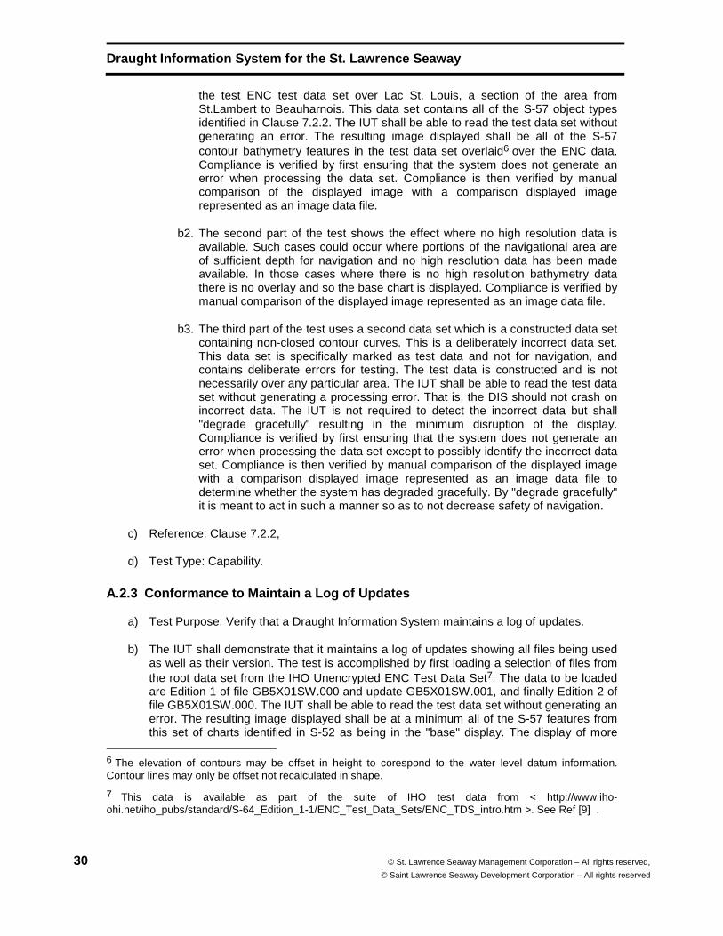
the test ENC test data set over Lac St. Louis, a section of the area from St.Lambert to Beauharnois. This data set contains all of the S-57 object types identified in Clause 7.2.2. The IUT shall be able to read the test data set without generating an error. The resulting image displayed shall be all of the S-57 contour bathymetry features in the test data set overlaid6 over the ENC data. Compliance is verified by first ensuring that the system does not generate an error when processing the data set. Compliance is then verified by manual comparison of the displayed image with a comparison displayed image represented as an image data file.
b2. The second part of the test shows the effect where no high resolution data is available. Such cases could occur where portions of the navigational area are of sufficient depth for navigation and no high resolution data has been made available. In those cases where there is no high resolution bathymetry data there is no overlay and so the base chart is displayed. Compliance is verified by manual comparison of the displayed image represented as an image data file.
b3. The third part of the test uses a second data set which is a constructed data set containing non-closed contour curves. This is a deliberately incorrect data set. This data set is specifically marked as test data and not for navigation, and contains deliberate errors for testing. The test data is constructed and is not necessarily over any particular area. The IUT shall be able to read the test data set without generating a processing error. That is, the DIS should not crash on incorrect data. The IUT is not required to detect the incorrect data but shall "degrade gracefully" resulting in the minimum disruption of the display. Compliance is verified by first ensuring that the system does not generate an error when processing the data set except to possibly identify the incorrect data set. Compliance is then verified by manual comparison of the displayed image with a comparison displayed image represented as an image data file to determine whether the system has degraded gracefully. By "degrade gracefully" it is meant to act in such a manner so as to not decrease safety of navigation.
c) Reference: Clause 7.2.2,
d) Test Type: Capability.
A.2.3 Conformance to Maintain a Log of Updates
a) Test Purpose: Verify that a Draught Information System maintains a log of updates.
b) The IUT shall demonstrate that it maintains a log of updates showing all files being used as well as their version. The test is accomplished by first loading a selection of files from the root data set from the IHO Unencrypted ENC Test Data Set7. The data to be loaded are Edition 1 of file GB5X01SW.000 and update GB5X01SW.001, and finally Edition 2 of file GB5X01SW.000. The IUT shall be able to read the test data set without generating an error. The resulting image displayed shall be at a minimum all of the S-57 features from this set of charts identified in S-52 as being in the "base" display. The display of more
6 The elevation of contours may be offset in height to corespond to the water level datum information. Contour lines may only be offset not recalculated in shape.
7 This data is available as part of the suite of IHO test data from < http://www.iho-ohi.net/iho_pubs/standard/S-64_Edition_1-1/ENC_Test_Data_Sets/ENC_TDS_intro.htm >. See Ref [9] .
Draught Information System for the St. Lawrence Sea way
© St.Lawrence Seaway Management Corporation – All rights reserved © Saint Lawrence Seaway Development Corporation – All rights reserved
31
than the base level features is also permitted. Compliance is verified by manually inspecting the update file to ensure that the history of the test S-57 data set and its replacement, and the corresponding contour bathymetry data set and its replacement are recorded in the log data file, and that the files and versions are recorded as being current.
c) Reference: Clause 7.2.3,
d) Test Type: Basic.
A.2.4 Conformance to Read and Process AIS Informati on
a) Test Purpose: Verify that a Draught Information System is able to read and process AIS "broadcast" binary message number 8, containing the Seaway AIS "Water Level" message number 3.
b) Test Method: The test is in two parts driven by two separate sets of test data.
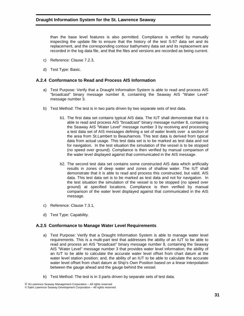
b1. The first data set contains typical AIS data. The IUT shall demonstrate that it is able to read and process AIS "broadcast" binary message number 8, containing the Seaway AIS "Water Level" message number 3 by receiving and processing a test data set of AIS messages defining a set of water levels over a section of the area from St.Lambert to Beauharnois. This test data is derived from typical data from actual usage. This test data set is to be marked as test data and not for navigation. In the test situation the simulation of the vessel is to be stopped (no speed over ground). Compliance is then verified by manual comparison of the water level displayed against that communicated in the AIS message.
b2. The second test data set contains some constructed AIS data which artificially results in zones of deep water and zones of shallow water. The IUT shall demonstrate that it is able to read and process this constructed, but valid, AIS data. This test data set is to be marked as test data and not for navigation. In the test situation the simulation of the vessel is to be stopped (no speed over ground) at specified locations. Compliance is then verified by manual comparison of the water level displayed against that communicated in the AIS message.
c) Reference: Clause 7.3.1,
d) Test Type: Capability.
A.2.5 Conformance to Manage Water Level Requirement s
a) Test Purpose: Verify that a Draught Information System is able to manage water level requirements. This is a multi-part test that addresses the ability of an IUT to be able to read and process an AIS "broadcast" binary message number 8, containing the Seaway AIS "Water Level" message number 3 that provides water level information; the ability of an IUT to be able to calculate the accurate water level offset from chart datum at the water level station position; and, the ability of an IUT to be able to calculate the accurate water level offset from chart datum at Ship's Own Position based on a linear interpolation between the gauge ahead and the gauge behind the vessel.
b) Test Method: The test is in 3 parts driven by separate sets of test data.
Draught Information System for the St. Lawrence Sea way
32 © St. Lawrence Seaway Management Corporation – All rights reserved,
© Saint Lawrence Seaway Development Corporation – All rights reserved
b1. The first test situation makes use of three test data sets. The first data set is the S-57 data over a section of the area from St. Lambert to Beauharnois. The second is the High Resolution Contour Bathymetry test data set over the same area. The third test data set contains typical AIS data. The IUT shall demonstrate that it is able to read and process AIS "broadcast" binary message number 8, containing the Seaway AIS "Water Level" message number 3 by receiving and processing the test data set of AIS messages defining a set of water levels over a section of the area from St. Lambert to Beauharnois. This test data is derived from typical data from actual usage. This test data set is to be marked as test data and not for navigation. In the test situation the simulation of the vessel is to be stopped (no speed over ground) at a location near a water level gauge. Compliance is then verified by manual comparison of the water level elevation at vessel location and / or water level offset at vessel location against the values provided in the test file. This verifies the complete chain of events from reading and processing AIS water level information to calculating the water level and displaying the resulting image.
b2. The second test situation makes use of the same test data sets with the ship position set between two water level gauges to show interpolation of water gauge levels. In the test situation the simulation of the vessel is to be stopped (no speed over ground) at a position between two water level gauges to show interpolation between the levels. Compliance is then verified by manual comparison of the water level elevation at vessel location and / or water level offset at vessel location against the values provided in the test file. This verifies the complete chain of events from reading and processing AIS water level information to calculating the water level and displaying the resulting image.
b3. The third test situation, in two (2) parts, makes use of some constructed AIS data in test data set which artificially results in zones of deep water and zones of shallow water. This test data set is to be marked as test data and not for navigation. This data is overlaid over a constructed S-57 chart that contains only the boundary of the test area and constructed high resolution contour bathymetry data that contains steps of different depths. The IUT shall demonstrate that it is able to read and process this constructed, but valid, AIS data. In the test situation the simulation of the vessel is to be stopped (no speed over ground). Compliance is then verified by having the DIS display a vessel with drafts of 80.8 dm stopped at prescribed locations, reading the provided water elevations and calculating the underkeel clearance. In the second part of the test, the DIS will display a vessel with drafts of 87.5 dm at a prescribed location, reading the provided water elevations and calculating the underkeel clearance.
c) Reference: 7.3,
d) Test Type: Capability.
A.2.6 Conformance to Determine Channel Type
a) Test Purpose: Verify that a Draught Information System is able to select the appropriate Squat Formula for the Channel Type through which the vessel is passing.
b) Test Method: The IUT shall demonstrate that it is able to select the appropriate Squat Formula for the Channel Type through which the vessel is passing by positioning the
Draught Information System for the St. Lawrence Sea way
© St.Lawrence Seaway Management Corporation – All rights reserved © Saint Lawrence Seaway Development Corporation – All rights reserved
33
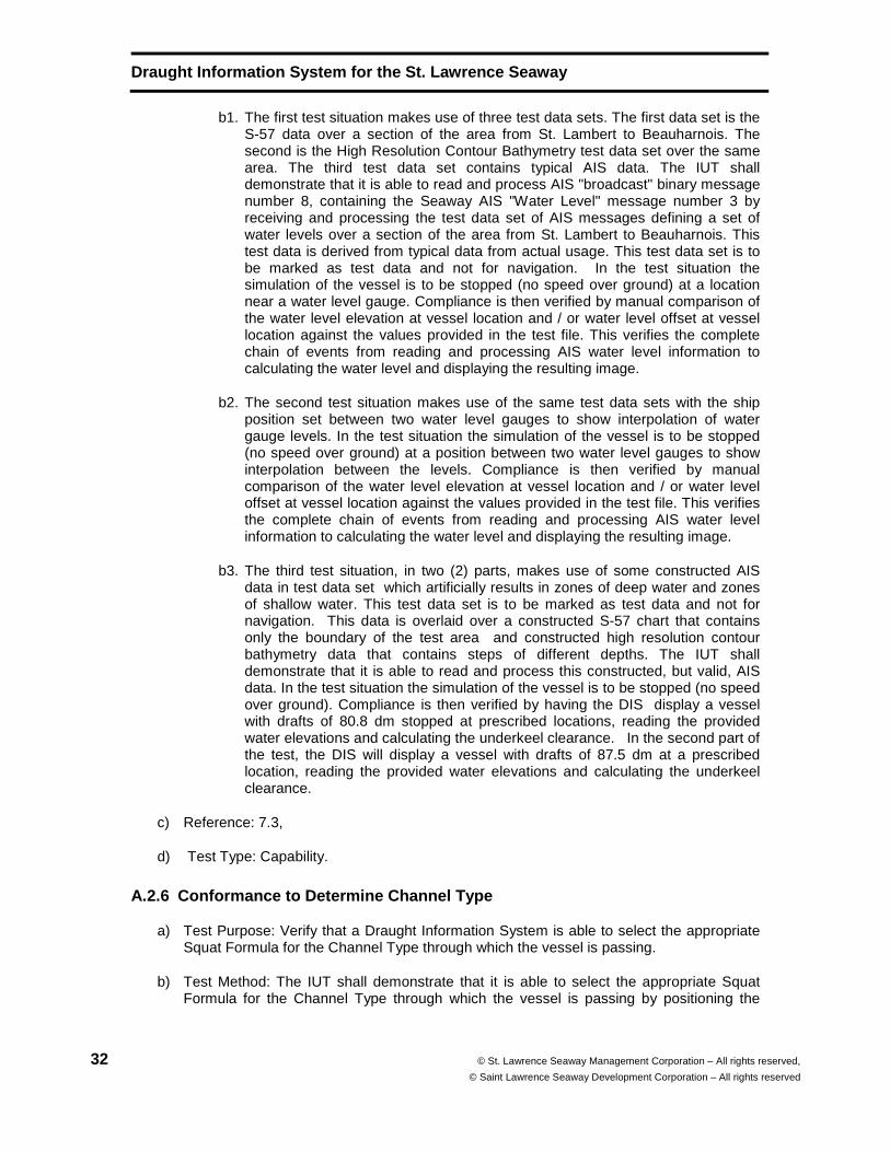
vessel in two locations, in a simulation of the system. The test is accomplished by first loading the test S-57 ENC data set over a section of the area from St.Lambert to Beauharnois and then loading the corresponding contour bathymetry data set. The vessel is then positioned between the Calling-in Point 2 and the St. Lambert Lock. The system should indicate that the squat formula to be used is of "Canal" type. The vessel is then positioned between Buoy A-1 and Buoy A-13. The system should indicate that the squat formula to be used is of "Shallow Lake" type. See Table 8.
c) Reference: Clause 7.2.3,
d) Test Type: Basic.
A.2.7 Conformance to Squat Equation Conditions
a) Test Purpose: Verify that a Draught Information System is capable of calculating estimated squat.
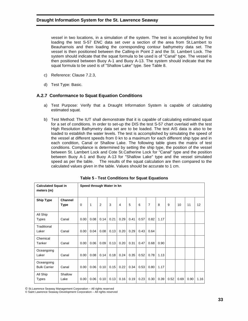
b) Test Method: The IUT shall demonstrate that it is capable of calculating estimated squat for a set of conditions. In order to set-up the DIS the test S-57 chart overlaid with the test High Resolution Bathymetry data set are to be loaded. The test AIS data is also to be loaded to establish the water levels. The test is accomplished by simulating the speed of the vessel at different speeds from 0 kn to a maximum for each different ship type and in each condition, Canal or Shallow Lake. The following table gives the matrix of test conditions. Compliance is determined by setting the ship type, the position of the vessel between St. Lambert Lock and Cote St.Catherine Lock for "Canal" type and the position between Buoy A-1 and Buoy A-13 for "Shallow Lake" type and the vessel simulated speed as per the table. The results of the squat calculation are then compared to the calculated values given in the table. Values should be accurate to 1 cm.
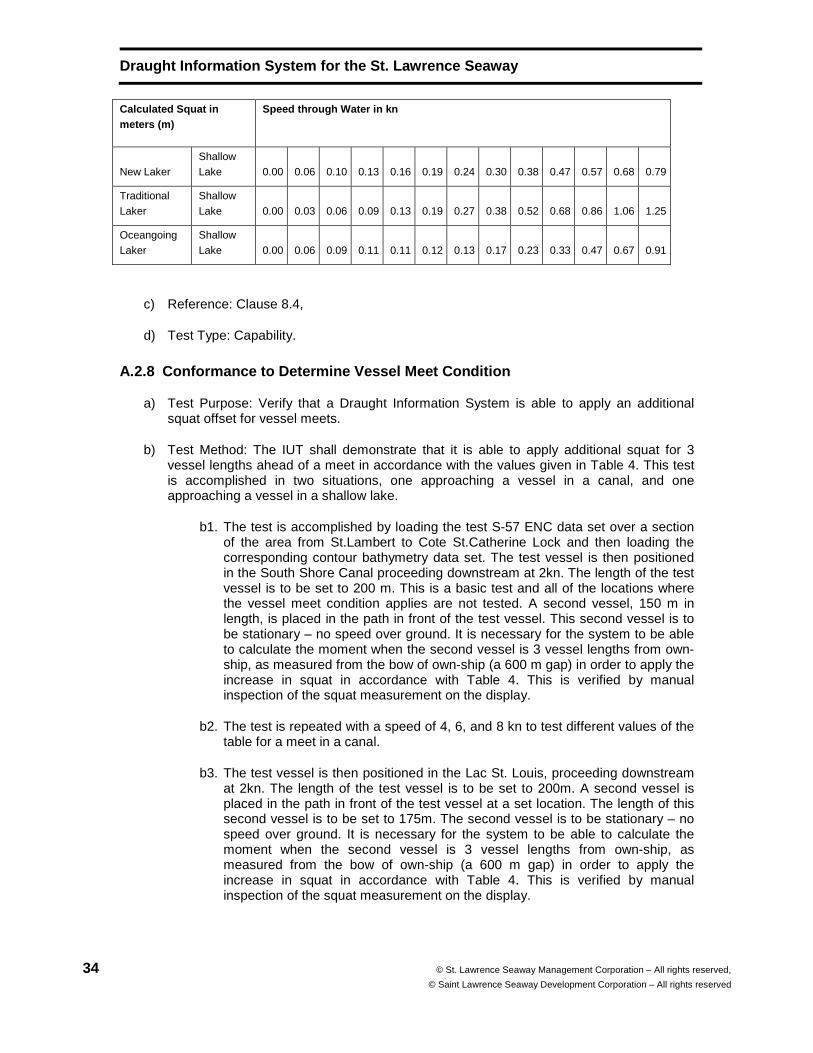
Table 5 - Test Conditions for Squat Equations
Calculated Squat in meters (m)
Speed through Water in kn
Ship Type Channel Type 0 1 2 3 4 5 6 7 8 9 10 11 12
All Ship Types Canal 0.00 0.08 0.14 0.21 0.29 0.41 0.57 0.82 1.17
Traditional Laker Canal 0.00 0.04 0.08 0.13 0.20 0.29 0.43 0.64
Chemical Tanker Canal 0.00 0.06 0.09 0.13 0.20 0.31 0.47 0.68 0.90
Oceangoing Laker Canal 0.00 0.08 0.14 0.18 0.24 0.35 0.52 0.78 1.13
Oceangoing Bulk Carrier Canal 0.00 0.06 0.10 0.15 0.22 0.34 0.53 0.80 1.17
All Ship Types
Shallow Lake 0.00 0.06 0.10 0.13 0.16 0.19 0.23 0.30 0.39 0.52 0.69 0.90 1.16
Draught Information System for the St. Lawrence Sea way
34 © St. Lawrence Seaway Management Corporation – All rights reserved,
© Saint Lawrence Seaway Development Corporation – All rights reserved
Calculated Squat in meters (m)
Speed through Water in kn
New Laker Shallow Lake 0.00 0.06 0.10 0.13 0.16 0.19 0.24 0.30 0.38 0.47 0.57 0.68 0.79
Traditional Laker
Shallow Lake 0.00 0.03 0.06 0.09 0.13 0.19 0.27 0.38 0.52 0.68 0.86 1.06 1.25
Oceangoing Laker
Shallow Lake 0.00 0.06 0.09 0.11 0.11 0.12 0.13 0.17 0.23 0.33 0.47 0.67 0.91
c) Reference: Clause 8.4,
d) Test Type: Capability.
A.2.8 Conformance to Determine Vessel Meet Conditio n
a) Test Purpose: Verify that a Draught Information System is able to apply an additional squat offset for vessel meets.
b) Test Method: The IUT shall demonstrate that it is able to apply additional squat for 3 vessel lengths ahead of a meet in accordance with the values given in Table 4. This test is accomplished in two situations, one approaching a vessel in a canal, and one approaching a vessel in a shallow lake.
b1. The test is accomplished by loading the test S-57 ENC data set over a section of the area from St.Lambert to Cote St.Catherine Lock and then loading the corresponding contour bathymetry data set. The test vessel is then positioned in the South Shore Canal proceeding downstream at 2kn. The length of the test vessel is to be set to 200 m. This is a basic test and all of the locations where the vessel meet condition applies are not tested. A second vessel, 150 m in length, is placed in the path in front of the test vessel. This second vessel is to be stationary – no speed over ground. It is necessary for the system to be able to calculate the moment when the second vessel is 3 vessel lengths from own-ship, as measured from the bow of own-ship (a 600 m gap) in order to apply the increase in squat in accordance with Table 4. This is verified by manual inspection of the squat measurement on the display.
b2. The test is repeated with a speed of 4, 6, and 8 kn to test different values of the table for a meet in a canal.
b3. The test vessel is then positioned in the Lac St. Louis, proceeding downstream at 2kn. The length of the test vessel is to be set to 200m. A second vessel is placed in the path in front of the test vessel at a set location. The length of this second vessel is to be set to 175m. The second vessel is to be stationary – no speed over ground. It is necessary for the system to be able to calculate the moment when the second vessel is 3 vessel lengths from own-ship, as measured from the bow of own-ship (a 600 m gap) in order to apply the increase in squat in accordance with Table 4. This is verified by manual inspection of the squat measurement on the display.
Draught Information System for the St. Lawrence Sea way
© St.Lawrence Seaway Management Corporation – All rights reserved © Saint Lawrence Seaway Development Corporation – All rights reserved
35
b4. The test is repeated with a speed of 4, 6, 8 and 10 kn to test different values of the table for a meet in a shallow lake.
c) Reference: 8.5,
d) Test Type: Basic.
A.2.9 Conformance to Determine Look-ahead Feature
a) Test Purpose: Verify that a Draught Information System supports a look-ahead feature to estimate conditions including vessel squat relative to current speed through water, calculated water levels from real-time water levels, and areas where the predicted UKC of the vessel is less than the minimum UKC specified by the Seaway. An actual outline of the limits of the look-ahead zone does not need to be drawn on the display.
b) Test Method: The IUT shall demonstrate that it maintains a look-ahead feature by showing areas in the look-ahead zone ahead of the vessel where the predicted UKC of the vessel is less than the minimum UKC specified by the Seaway. The look-ahead zone is a minimum of 6 minutes travel for the vessel at its current speed. It may be calculated from the current speed of the vessel and displayed, or it may be set to a greater amount, as indicated in Clause B.1.3 The test is accomplished by first loading the test S-57 ENC data set over a section of the area from St.Lambert to Beauharnois and then loading the corresponding contour bathymetry data set and then loading AIS test data. Compliance is verified by manually inspecting the display to ensure that a graphical representation of areas where the predicted UKC of the vessel is less than the minimum UKC specified by the Seaway is presented. A documentation file is provided with the test data set which contains the test vessel locations, speed, water level readings and other parameters required for validation.
c) Reference: Clause 8.6.
d) Test Type: Basic.
A.2.10 Conformance to Verify Display Requirements
a) Test Purpose: Verify that a Draught Information System meets the display requirements.
b) Test Method: The IUT shall demonstrate that it is able to display on a single DIS display all information relating to safe navigation as applicable to a DIS, including projected under keel clearance for the look-ahead zone and other related parameters. The test is a multi-part test that addresses the display of information overlaid on an ENC, and support information that is to be displayed at all times and information which is to be made available upon request.
b1. The first test is accomplished by loading the test S-57 ENC data set over a section of the area from St.Lambert to Beauharnois and then loading the corresponding contour bathymetry data set and the test AIS data set. The vessel should be set to All Ships type and the draught of the ship set so that both safe and unsafe areas are visible. Conformance is verified by manually examining the display to ensure that areas of water where the predicted UKC of the vessel is less than the minimum UKC specified by the Seaway are visible in the look-ahead zone in front of the vessel.
Draught Information System for the St. Lawrence Sea way
36 © St. Lawrence Seaway Management Corporation – All rights reserved,
© Saint Lawrence Seaway Development Corporation – All rights reserved
b2. The second test is accomplished by manually examining the display to ensure that the following list of values / status are automatically displayed and updated at a rate of once per second.
• Heading • Course Over Ground • Speed Through Water or Calculated Speed Through Water • Individual identification of areas where the minimum UKC is
breached for all high resolution bathymetry data inside the look-ahead zone
• Under Keel Clearance • Water level offset from chart datum for the high resolution
bathymetry data or, if unavailable, the water level offset for the chart within the look-ahead zone
b3. The third test is accomplished by manually examining the display to ensure that
the following list of values / status are possible to be displayed upon request and are updated at a rate of once per second.
� Date and Time of observation in the format of Date/Hour:Minute:Second � ID of the water level station used by the system to determine water levels
in front of Own-Ship � Elevations of the water above reference datum (i.e. IGLD-85 for the
Seaway) of the water level station used by the system to determine the water levels in front of Own-Ship;
� Water level offset from chart datum of the chart at the location of the water level station used by the system to determine water level in front of Own-Ship;
� ID of the water level station used by the system behind Own-Ship � Elevation of the water above reference datum (i.e. IGLD-85 for the
Seaway) of the water level station used by the system behind Own-Ship � Water level offset from chart datum of the chart at the location of the
water level station used by the system behind Own-Ship � ID of the water level station used by the system at Own-Ship � Elevation of the water above reference datum (i.e. IGLD-85 for the
Seaway) at Own-Ship � Water level offset from chart datum of the chart at the location of Own-
Ship � Individual identification of areas where the minimum UKC is breached � Ship type of Own-Ship. (from list of types in Table 1) � Channel type as used by the squat formulas
• Canal • Shallow Lake
� Indication if a manual water level offset is applied.
c) Reference:9.1,
d) Test Type: Basic.
Draught Information System for the St. Lawrence Sea way
© St.Lawrence Seaway Management Corporation – All rights reserved © Saint Lawrence Seaway Development Corporation – All rights reserved
37
A.2.11 Conformance to Verify Recording Requirements
a) Test Purpose: Verify that a Draught Information System is capable of recording the voyage of the vessel and the route, under keel clearance, water levels and other parameters needed to be able to replay the voyage.
b) Test Method: The IUT shall demonstrate that it maintains a record of all of the parameters identified in Annex B Recording Requirements. Conformance is verified by running a simulated voyage using the available test data and then manually examining the recorded information to ensure that each item in the list given in Annex B is recorded with a playback interval of 2 seconds. This is to be a 2-second recording interval and not an estimated value based on an interpolation between more broadly spaced recording times. The ability to provide a playback of a voyage is a mandatory requirement of the DIS.
c) Reference: Clause 9.2,
d) Test Type: Basic.
A.2.12 Conformance to Verify General Requirements
a) Test Purpose: Verify that a Draught Information System supports the general requirements for hardware and software given in Clause 9.4.
b) Test Method: The test is in three parts.
b1. The first test is to verify that the hardware shall not interfere with required navigation equipment in regard to EMI (Electro Magnetic Interference). Conformance is only tested by manual inspection of the system and any other adjacent systems.
b2. The second test is to determine that the monitors are suitable for night vision on a vessel. Conformance is verified by either ensuring that the monitor used is marked as compliant with IEC 60945 with respect to display characteristics, or by performing the tests for night vision compliance as referenced in IEC 60945.
b3. The third test is to determine that the software used to implement the DIS should be such that during normal operation, minimal input is required from the navigator and that alarms are clear but do not overload the operator. Conformance is verified by ensuring that the DIS system is capable of generating alarms combined with appropriate alerts for the following conditions. This is done by running the test data set to trigger an UKC alarm, by running the test data set to trigger a Squat Curve alarm, and by processing the log file that identifies the Operational Data Invalid alarm. Since the Sounder alarm is optional there is no standardized test.
Draught Information System for the St. Lawrence Sea way
38 © St. Lawrence Seaway Management Corporation – All rights reserved,
© Saint Lawrence Seaway Development Corporation – All rights reserved
• UKC alarm .
• Squat Curve alarm
• Operational Data Invalid alarm
• Sounder alarm (This alarm is optional since the availability of an echo-sounder is optional.)
b4. The specifications (7.3.1 AIS information) require that the system read water level information transmitted via the Seaway’s AIS network. It also states that ‘If the AIS system transmits an estimated water value this should be recognized and identified to the mariner.’ The data set ‘estimated_vs_actual_value_alert_A212.log’ will test for any alerts generated when an estimated (or calculated) water level is broadcast instead of a reading from the primary gauge for a given location.
c) Reference: Clause 9.4, E.2
d) Test Type: Basic.
Draught Information System for the St. Lawrence Sea way
© St.Lawrence Seaway Management Corporation – All rights reserved © Saint Lawrence Seaway Development Corporation – All rights reserved
39
Annex B (normative) Recording Requirements
B.1 Overview
B.1.1 Introduction
The Draught Information System shall record the voyage of the vessel and the route, under keel clearance, water levels and other parameters needed to be able to replay the voyage. A voyage is any identifiable mechanism of describing the transit of a vessel in the Seaway. This may be different between manufacturers. The recording shall include sufficient data to allow a full playback of the voyage on the same version of the Draught Information System.
The system shall also be able to output a record of the voyage as a file that contains a record of the route of the vessel, the water levels, the bathymetric data used and the sensor data received over any time period requested by the Seaway for operational and legal purposes. The data can be held as electronic records as long as it can be extracted on demand to produce external records as required.
B.1.2 Values to be Reproduced at Time of Playback
Note: At a minimum the status shall be recorded eve ry 2 seconds.
• Latitude / Longitude of Own-Ship • Heading of Own-Ship • Course over Ground of Own-Ship • Speed over Ground of Own-Ship • Calculated Speed Through water of Own-Ship • Accurate outline of Own-Ship when representation of this outline is 6mm or larger on the
screen. If the representation of this outline is smaller than 6 mm the vessel is represented by the Own-Ship icon
• Ship type of Own-Ship (from list of types in Table 1). • Area type as used by the squat formulas
o Channel o Shallow lake
• Draught of Own-Ship. (Resolution 0.01 metre) • Minimum UKC of Own-Ship (Seaway specified 0.3 metre) • ID of the water level station used by the system in front of Own-Ship • Elevation of the water above reference datum (i.e. IGLD-85 for the Seaway) of the water
level station used by the system in front of Own-Ship • Water level offset from chart datum of the chart at the location of the water level station
used by the system in front of Own-Ship • ID of the water level station used by the system behind Own-Ship • Elevation of the water above reference datum (i.e. IGLD-85 for the Seaway) of the water
level station used by the system behind Own-Ship • Water level offset from chart datum of the chart at the location of the water level station
used by the system behind Own-Ship
Draught Information System for the St. Lawrence Sea way
40 © St. Lawrence Seaway Management Corporation – All rights reserved,
© Saint Lawrence Seaway Development Corporation – All rights reserved
• Elevation of the water above reference datum (i.e. IGLD-85 for the Seaway) at Own-Ship • Water level offset from chart datum at the location of Own-Ship • Individual identification of areas where the minimum UKC is breached • Indication of whether a manual water level offset has been applied and the value applied.
B.1.3 Records to be Held Onboard of the Vessel
• Revision and installation dates for all charts including high resolution bathymetry data used during the passage
• All values entered manually into the system o Ship type of Own-Ship o Draught of Own-Ship o Minimum UKC o Length of the look-ahead zone in front of Own-Ship (if other than the default)
Note: The look-ahead zone is a minimum of 6 minutes at the current speed, but can be more.
Note: When squat is influenced by the position of a second vessel, the position of that vessel should be part of the recorded data. AIS targets (other vessels) should be tracked and recorded as part of the history of the voyage. Therefore the following items should be recorded.
• Latitude / Longitude of any AIS targets • Heading of any AIS targets • Course over Ground of any AIS targets • Speed over Ground of any AIS targets • AIS vessel type of any AIS targets • Accurate outline of any AIS targets when representation of this outline is 6mm or larger
on the screen. If the representation of this outline is smaller than 6 mm the vessels are represented by the AIS icon. Note: The 6mm outline specification is defined in S-57 and S-52.
• Name and MMSI of the vessel.
The data required for playbacks, including revisions, versions, installation dates and manually entered values shall be held onboard of the vessel for a minimum period of 14 days after the vessel completes its transit of the Seaway System.
Records of revisions, installation dates and manually entered values shall be in electronic format and may also be held in paper format. These records shall be held for (6) years.
WD Draught Information System for the St. Lawrence Seaway
41 © St. Lawrence Seaway Management Corporation – All rights reserved,
© Saint Lawrence Seaway Development Corporation – All rights reserved
Annex C (normative) Draught Information Parameters Specific to
the St. Lawrence Seaway
C.1 Introduction
This document is defined as a generic specification that may be applied as an aid to navigation in a number of situations. However, it is specifically established for use in the St. Lawrence Seaway between Montreal and Lake Ontario and the Welland Canal. This annex defines the specific parameters that apply to the St. Lawrence Seaway as of the publication date of this document. These parameters may be updated by the St. Lawrence Seaways as appropriate, by published regulations.
C.2 Minimum Under Keel Clearance
The minimum under keel clearance for the St. Lawrence Seaway shall be 0.30 meters.
C.3 High Resolution Bathymetry
The content of the S-57 hydrographic chart for high resolution bathymetry data is defined by the national Hydrographic Office. In Canada this is The Canadian Hydrographic Service, and in the United States this is NOAA Coast and Geodetic Survey.
The high resolution bathymetry data shall have 10 cm contour lines in IHO S-57 format as supplied by the Seaway Corporations or national hydrographic office8.
C.4 Water Level Datum
The water level datum used in the St. Lawrence Seaway is the International Great Lakes Datum 1985. (IGLD-85).
C.5 Water Level Interpolation
The Draught Information System shall be able to calculate the accurate water level at Ship's Own Position based on a linear interpolation between the closest water level station(s) in the Seaway.
8 Canadian Hydrographic Service or US NOAA Coast and Geodetic Survey
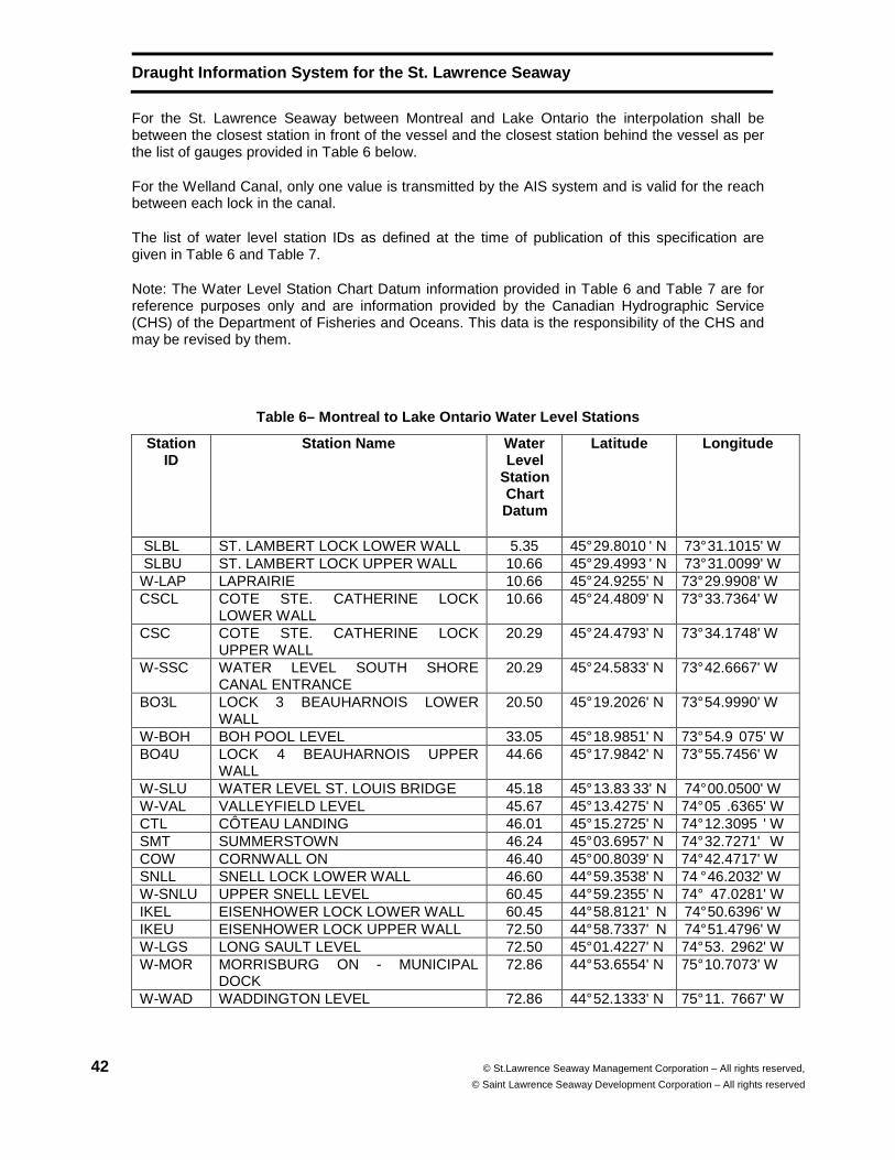
Draught Information System for the St. Lawrence Sea way
42 © St.Lawrence Seaway Management Corporation – All rights reserved,
© Saint Lawrence Seaway Development Corporation – All rights reserved
For the St. Lawrence Seaway between Montreal and Lake Ontario the interpolation shall be between the closest station in front of the vessel and the closest station behind the vessel as per the list of gauges provided in Table 6 below.
For the Welland Canal, only one value is transmitted by the AIS system and is valid for the reach between each lock in the canal.
The list of water level station IDs as defined at the time of publication of this specification are given in Table 6 and Table 7.
Note: The Water Level Station Chart Datum information provided in Table 6 and Table 7 are for reference purposes only and are information provided by the Canadian Hydrographic Service (CHS) of the Department of Fisheries and Oceans. This data is the responsibility of the CHS and may be revised by them.
Table 6– Montreal to Lake Ontario Water Level Stati ons
Station ID
Station Name Water Level
Station Chart Datum
Lat itude Long itude
SLBL ST. LAMBERT LOCK LOWER WALL 5.35 45° 29.8010 ' N 73° 31.1015' W SLBU ST. LAMBERT LOCK UPPER WALL 10.66 45° 29.4993 ' N 73° 31.0099' W W-LAP LAPRAIRIE 10.66 45° 24.9255' N 73° 29.9908' W CSCL COTE STE. CATHERINE LOCK
LOWER WALL 10.66 45° 24.4809' N 73° 33.7364' W
CSC COTE STE. CATHERINE LOCK UPPER WALL
20.29 45° 24.4793' N 73° 34.1748' W
W-SSC WATER LEVEL SOUTH SHORE CANAL ENTRANCE
20.29 45° 24.5833' N 73° 42.6667' W
BO3L LOCK 3 BEAUHARNOIS LOWER WALL
20.50 45° 19.2026' N 73° 54.9990' W
W-BOH BOH POOL LEVEL 33.05 45° 18.9851' N 73° 54.9 075' W BO4U LOCK 4 BEAUHARNOIS UPPER
WALL 44.66 45° 17.9842' N 73° 55.7456' W
W-SLU WATER LEVEL ST. LOUIS BRIDGE 45.18 45° 13.83 33' N 74° 00.0500' W W-VAL VALLEYFIELD LEVEL 45.67 45° 13.4275' N 74° 05 .6365' W CTL CÔTEAU LANDING 46.01 45° 15.2725' N 74° 12.3095 ' W SMT SUMMERSTOWN 46.24 45° 03.6957' N 74° 32.7271' W COW CORNWALL ON 46.40 45° 00.8039' N 74° 42.4717' W SNLL SNELL LOCK LOWER WALL 46.60 44° 59.3538' N 74 ° 46.2032' W W-SNLU UPPER SNELL LEVEL 60.45 44° 59.2355' N 74° 47.0281' W IKEL EISENHOWER LOCK LOWER WALL 60.45 44° 58.8121' N 74° 50.6396' W IKEU EISENHOWER LOCK UPPER WALL 72.50 44° 58.7337' N 74° 51.4796' W W-LGS LONG SAULT LEVEL 72.50 45° 01.4227' N 74° 53. 2962' W W-MOR MORRISBURG ON - MUNICIPAL
DOCK 72.86 44° 53.6554' N 75° 10.7073' W
W-WAD WADDINGTON LEVEL 72.86 44° 52.1333' N 75° 11. 7667' W
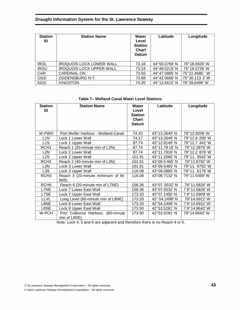
Draught Information System for the St. Lawrence Sea way
© St.Lawrence Seaway Management Corporation – All rights reserved,
© Saint Lawrence Seaway Development Corporation – All rights reserved 43
Station ID
Station Name Water Level
Station Chart Datum
Lat itude Long itude
IROL IROQUOIS LOCK LOWER WALL 73.18 44° 50.0769' N 75° 18.6920' W IROU IROQUOIS LOCK UPPER WALL 73.24 44° 49.5219' N 75° 19.0736' W CAR CARDINAL ON 73.50 44° 47.0885' N 75° 22.4685' W OGD OGDENSBURG N.Y. 73.88 44° 42.0666' N 75° 30.113 2' W KGN KINGSTON 74.20 44° 13.6615' N 76° 28.6496' W
Table 7– Welland Canal Water Level Stations
Station ID
Station Name Water Level
Station Chart Datum
Latitude Longitude
W-PWH Port Weller Harbour - Welland Canal 74.20 43° 13.2649' N 79° 12.9209' W L1N Lock 1 Lower Wall 74.17 43° 13.2649' N 79° 12.9 209' W L1S Lock 1 Upper Wall 87.74 43° 12.8149' N 79° 12.7 442' W
RCH1 Reach 1 (20-minute min of L2N) 87.74 43° 11.78 16' N 79° 12.2876' W L2N Lock 2 Lower Wall 87.74 43° 11.7816' N 79° 12.2 876' W L2S Lock 2 Upper Wall 101.91 43° 11.2065' N 79° 11. 9542' W
RCH2 Reach 2 (40-minute min of L3N) 101.91 43° 09.5 465' N 79° 11.6792' W L3N Lock 3 Lower Wall 101.91 43° 09.5465' N 79° 11. 6792' W L3S Lock 3 Upper Wall 116.08 43° 09.0865' N 79° 11. 6176' W
RCH3 Reach 3 (20-minute minimum of W-B05)
116.08 43° 08.7132' N 79° 11.5459' W
RCH6 Reach 6 (20-minute min of L7NE) 158.36 43° 07 .5532' N 79° 11.5826' W L7NE Lock 7 Lower East Wall 158.36 43° 07.5532' N 7 9° 11.5826' W L7SE Lock 7 Upper East Wall 173.33 43° 07.1450' N 7 9° 11.6909' W LLVL Long Level (60-minute min of L8NE) 173.33 42° 54.2498' N 79° 14.6912' W L8NE Lock 8 Lower East Wall 173.33 42° 54.2498' N 7 9° 14.6912' W L8SE Lock 8 Upper East Wall 173.50 42° 53.5281' N 7 9° 14.8642' W
W-PCH Port Colborne Harbour, (60-minute min of L8SE)
173.50 42° 53.5281' N 79° 14.8642' W
Note: Lock 4, 5 and 6 are adjacent and therefore there is no Reach 4 or 5.
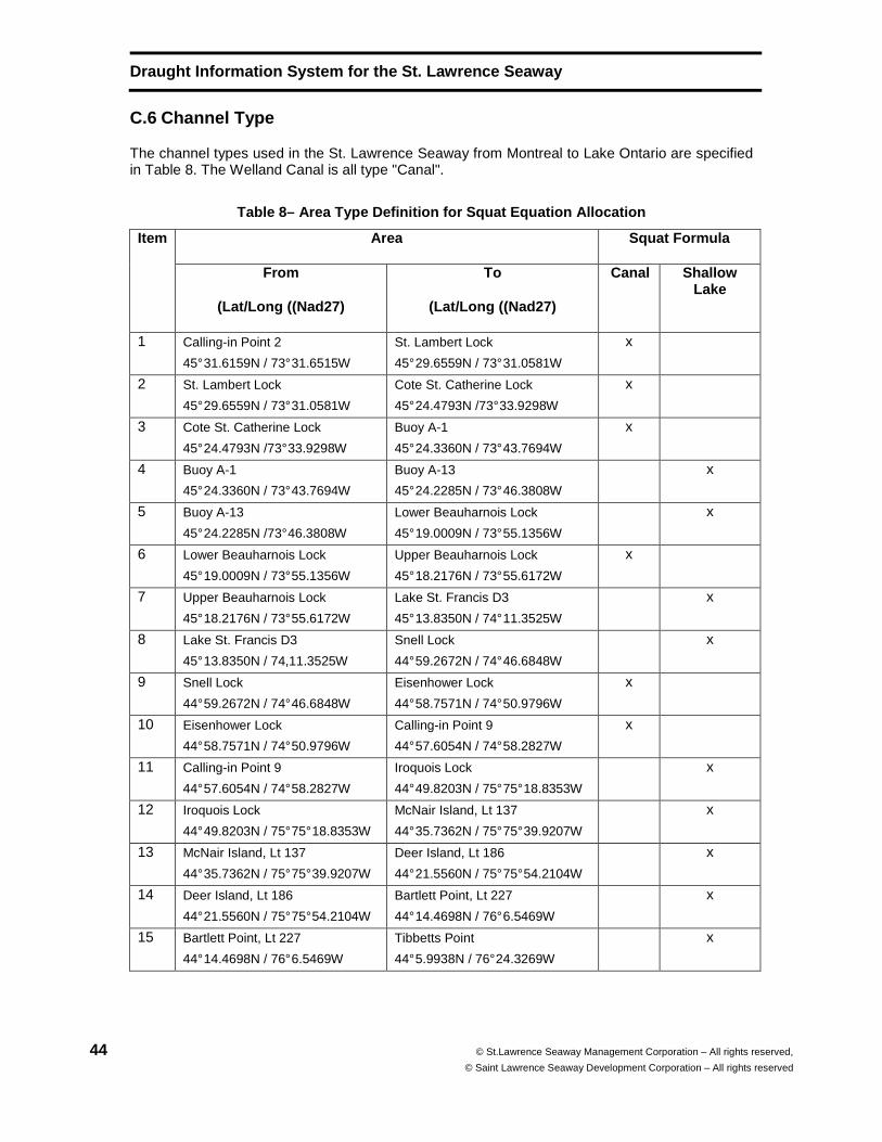
Draught Information System for the St. Lawrence Sea way
44 © St.Lawrence Seaway Management Corporation – All rights reserved,
© Saint Lawrence Seaway Development Corporation – All rights reserved
C.6 Channel Type
The channel types used in the St. Lawrence Seaway from Montreal to Lake Ontario are specified in Table 8. The Welland Canal is all type "Canal".
Table 8– Area Type Definition for Squat Equation Al location
Item Area Squat Formula
From
(Lat/Long ((Nad27)
To
(Lat/Long ((Nad27)
Canal Shallow Lake
1 Calling-in Point 2
45° 31.6159N / 73° 31.6515W
St. Lambert Lock
45° 29.6559N / 73° 31.0581W
x
2 St. Lambert Lock
45° 29.6559N / 73° 31.0581W
Cote St. Catherine Lock
45° 24.4793N /73° 33.9298W
x
3 Cote St. Catherine Lock
45° 24.4793N /73° 33.9298W
Buoy A-1
45° 24.3360N / 73° 43.7694W
x
4 Buoy A-1
45° 24.3360N / 73° 43.7694W
Buoy A-13
45° 24.2285N / 73° 46.3808W
x
5 Buoy A-13
45° 24.2285N /73° 46.3808W
Lower Beauharnois Lock
45° 19.0009N / 73° 55.1356W
x
6 Lower Beauharnois Lock
45° 19.0009N / 73° 55.1356W
Upper Beauharnois Lock
45° 18.2176N / 73° 55.6172W
x
7 Upper Beauharnois Lock
45° 18.2176N / 73° 55.6172W
Lake St. Francis D3
45° 13.8350N / 74° 11.3525W
x
8 Lake St. Francis D3
45° 13.8350N / 74,11.3525W
Snell Lock
44° 59.2672N / 74° 46.6848W
x
9 Snell Lock
44° 59.2672N / 74° 46.6848W
Eisenhower Lock
44° 58.7571N / 74° 50.9796W
x
10 Eisenhower Lock
44° 58.7571N / 74° 50.9796W
Calling-in Point 9
44° 57.6054N / 74° 58.2827W
x
11 Calling-in Point 9
44° 57.6054N / 74° 58.2827W
Iroquois Lock
44° 49.8203N / 75° 75° 18.8353W
x
12 Iroquois Lock
44° 49.8203N / 75° 75° 18.8353W
McNair Island, Lt 137
44° 35.7362N / 75° 75° 39.9207W
x
13 McNair Island, Lt 137
44° 35.7362N / 75° 75° 39.9207W
Deer Island, Lt 186
44° 21.5560N / 75° 75° 54.2104W
x
14 Deer Island, Lt 186
44° 21.5560N / 75° 75° 54.2104W
Bartlett Point, Lt 227
44° 14.4698N / 76° 6.5469W
x
15 Bartlett Point, Lt 227
44° 14.4698N / 76° 6.5469W
Tibbetts Point
44° 5.9938N / 76° 24.3269W
x

Draught Information System for the St. Lawrence Sea way
© St.Lawrence Seaway Management Corporation – All rights reserved,
© Saint Lawrence Seaway Development Corporation – All rights reserved 45
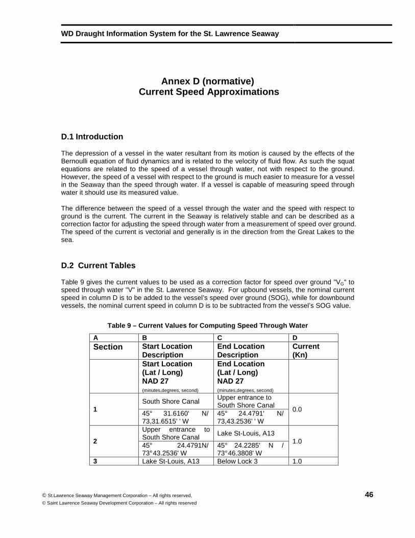
WD Draught Information System for the St. Lawrence Seaway
© St.Lawrence Seaway Management Corporation – All rights reserved,
© Saint Lawrence Seaway Development Corporation – All rights reserved 46
Annex D (normative) Current Speed Approximations
D.1 Introduction
The depression of a vessel in the water resultant from its motion is caused by the effects of the Bernoulli equation of fluid dynamics and is related to the velocity of fluid flow. As such the squat equations are related to the speed of a vessel through water, not with respect to the ground. However, the speed of a vessel with respect to the ground is much easier to measure for a vessel in the Seaway than the speed through water. If a vessel is capable of measuring speed through water it should use its measured value.
The difference between the speed of a vessel through the water and the speed with respect to ground is the current. The current in the Seaway is relatively stable and can be described as a correction factor for adjusting the speed through water from a measurement of speed over ground. The speed of the current is vectorial and generally is in the direction from the Great Lakes to the sea.
D.2 Current Tables
Table 9 gives the current values to be used as a correction factor for speed over ground "VG" to speed through water "V" in the St. Lawrence Seaway. For upbound vessels, the nominal current speed in column D is to be added to the vessel’s speed over ground (SOG), while for downbound vessels, the nominal current speed in column D is to be subtracted from the vessel’s SOG value.
Table 9 – Current Values for Computing Speed Throug h Water
A B C D Section Start Location
Description End Location Description
Current (Kn)
Start Location (Lat / Long) NAD 27 (minutes,degrees, second)
End Location (Lat / Long) NAD 27 (minutes,degrees, second)
1 South Shore Canal
Upper entrance to South Shore Canal
0.0 45° 31.6160' N/ 73,31.6515' ' W
45° 24.4791' N/ 73,43.2536' ' W
2
Upper entrance to South Shore Canal
Lake St-Louis, A13 1.0
45° 24.4791N/ 73° 43.2536' W
45° 24.2285' N / 73° 46.3808' W
3 Lake St-Louis, A13 Below Lock 3 1.0
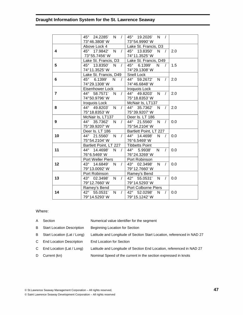
Draught Information System for the St. Lawrence Sea way
© St.Lawrence Seaway Management Corporation – All rights reserved,
© Saint Lawrence Seaway Development Corporation – All rights reserved 47
45° 24.2285' N / 73° 46.3808' W
45° 19.2026' N / 73° 54.9990' W
4 Above Lock 4 Lake St. Francis, D3
2.0 45° 17.9842' N / 73° 55.7456' W
45° 13.8350' N / 74° 11.3525' W
5 Lake St. Francis, D3 Lake St. Francis, D49
1.5 45° 13.8350' N / 74° 11.3525' W
45° 6.1399' N / 74° 29.1308' W
6 Lake St. Francis, D49 Snell Lock
2.0 45° 6.1399' N / 74° 29.1308' W
44° 59.2672' N / 74° 46.6848' W
7 Eisenhower Lock Iroquois Lock
2.0 44° 58.7571' N / 74° 50.9796' W
44° 49.8203' N / 75° 18.8353' W
8 Iroquois Lock McNair Is, LT137
2.0 44° 49.8203' N / 75° 18.8353' W
44° 35.7362' N / 75° 39.9207' W
9 McNair Is, LT137 Deer Is. LT 186
0.0 44° 35.7362' N / 75° 39.9207' W
44° 21.5560' N / 75° 54.2104' W
10 Deer Is. LT 186 Bartlett Point, LT 227
0.0 44° 21.5560' N / 75° 54.2104' W
44° 14.4698' N / 76° 6.5469' W
11 Bartlett Point, LT 227 Tibbetts Point
0.0 44° 14.4698' N / 76° 6.5469' W
44° 5.9938' N / 76° 24.3269' W
12 Port Weller Piers Port Robinson
0.0 43° 14.6849' N / 79° 13.0092' W
43° 02.3498' N / 79° 12.7660' W
13 Port Robinson Ramey’s Bend
0.0 43° 02.3498' N / 79° 12.7660' W
42° 55.0531' N / 79° 14.5293' W
14 Ramey’s Bend Port Colborne Piers
0.0 42° 55.0531' N / 79° 14.5293' W
42° 52.0298' N / 79° 15.1242' W
Where:
A Section Numerical value identifier for the segment
B Start Location Description Beginning Location for Section
B Start Location (Lat / Long) Latitude and Longitude of Section Start Location, referenced in NAD 27
C End Location Description End Location for Section
C End Location (Lat / Long) Latitude and Longitude of Section End Location, referenced in NAD 27
D Current (kn) Nominal Speed of the current in the section expressed in knots

Draught Information System for the St. Lawrence Sea way
48 © St.Lawrence Seaway Management Corporation – All rights reserved,
© Saint Lawrence Seaway Development Corporation – All rights reserved
Note: For the purposes of the DIS the value of 0 is used in this table to imply a value that is insignificant but not necessarily exactly 0.
WD Draught Information System for the St. Lawrence Seaway
© St.Lawrence Seaway Management Corporation – All rights reserved,
© Saint Lawrence Seaway Development Corporation – All rights reserved 49
Annex E (normative) Alarms and Alerts
E.1 Alarm and Alert Environment
The Draught Information System shall generate alarms and alerts to indicate conditions which must be brought to the attention of a ship operator. The system manufacturer is free to design the human interface to the equipment but should ensure that the alarms and alerts are implemented in such a manner so that the operator is likely to pay attention to those alarms that are important for safe operation of the vessel. There are many alarms that may occur on the bridge of a ship, and it is easy for the Draught Information System to be lost in a cacophony of other alarms. Also, too many alarms, especially those that convey little relevant information, generate confusion and reduce the likelihood that important information will be addressed by the operator. The system should provide a good balance between alarms and associated alerts for important information, and alerts for less important information.
An alarm is an audio or other intrusive signal (such as a flashing light). An alert is any other method of indicating information that needs to be addressed by the operator, such as a message on the display screen. Alerts may draw attention, such as flashing, drawing an object such as an unsafe area in red or otherwise being obvious, but addressing an alert is under the control of an operator. A combination of alarms and alerts can provide a good level of user interaction.
E.2 Alarm and Alert Conditions
The following conditions shall generate alarms combined with appropriate alerts .
UKC alarm generated when the predicted UKC of the vessel is less than the minimum UKC specified by the Seaway, in the look-ahead zone. The areas where the predicted UKC of the vessel is less than the minimum UKC specified by the Seaway are to be marked red in the look-ahead zone of the display of bathymetric data and an appropriate alarm generated. The manufacturer is free to provide a larger look-ahead zone than the minimum 6 minutes at the current speed recommended.
Note: Clearly marking areas where the predicted UKC of the vessel is less than the minimum UKC specified by the Seaway using the S-52 colour token “DNGHL” danger highlight symbol is an acceptable way of alerting the mariner of areas ahead where the minimum UKC will be compromised.
Squat Curve alarm generated when the actual speed of the vessel through water exceeds the upper limit of the range of applicability of the squat equation.

Draught Information System for the St. Lawrence Sea way
50 © St.Lawrence Seaway Management Corporation – All rights reserved,
© Saint Lawrence Seaway Development Corporation – All rights reserved
Operational data invalid alarm - generated when the AIS, GPS, or Gyro sensor input to the system is invalid, or the water level AIS message has not been updated for more than 12 minutes. This alarm and the associated alert detailing the issue, is generated if no data is received from the corresponding sensor or data source or the data is invalid in areas where it is required.
Sounder alarm generated if the UKC as measured by a sounder is less than the UKC calculated using the squat equations. This alarm is optional since the availability of an echo sounder is optional. [see 9.1]
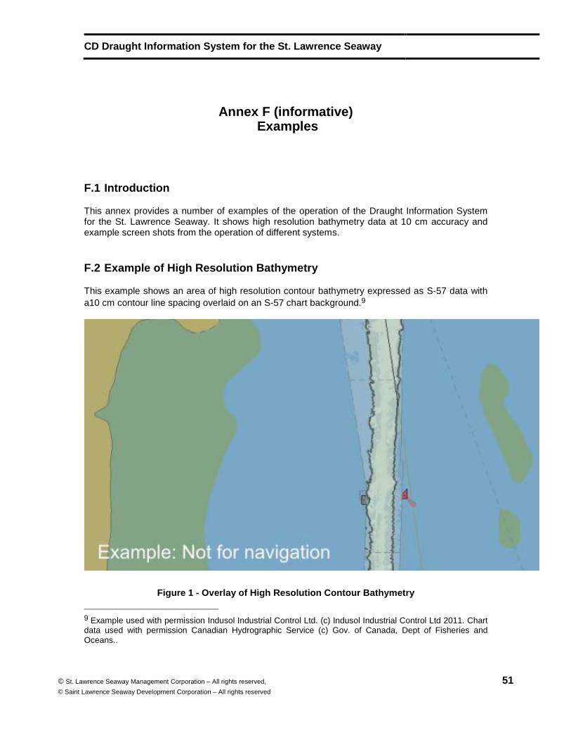
CD Draught Information System for the St. Lawrence Seaway
© St. Lawrence Seaway Management Corporation – All rights reserved,
© Saint Lawrence Seaway Development Corporation – All rights reserved 51
Annex F (informative) Examples
F.1 Introduction
This annex provides a number of examples of the operation of the Draught Information System for the St. Lawrence Seaway. It shows high resolution bathymetry data at 10 cm accuracy and example screen shots from the operation of different systems.
F.2 Example of High Resolution Bathymetry
This example shows an area of high resolution contour bathymetry expressed as S-57 data with a10 cm contour line spacing overlaid on an S-57 chart background.9
Figure 1 - Overlay of High Resolution Contour Bathy metry
9 Example used with permission Indusol Industrial Control Ltd. (c) Indusol Industrial Control Ltd 2011. Chart data used with permission Canadian Hydrographic Service (c) Gov. of Canada, Dept of Fisheries and Oceans..
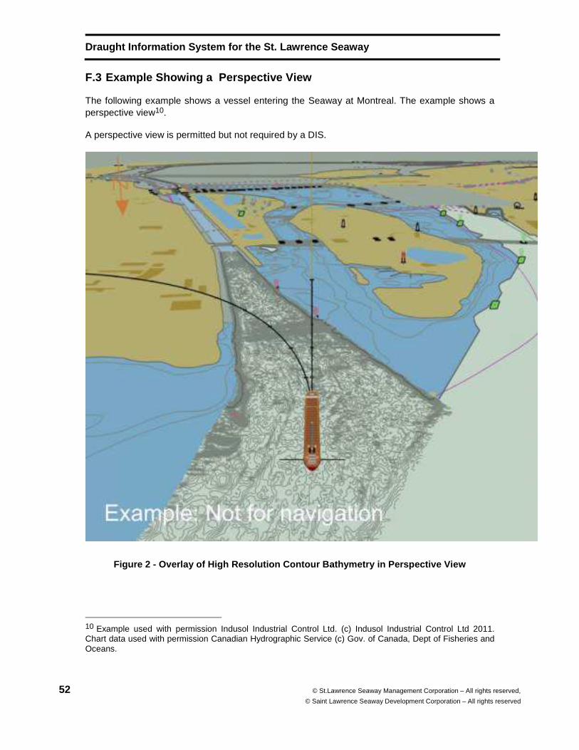
Draught Information System for the St. Lawrence Sea way
52 © St.Lawrence Seaway Management Corporation – All rights reserved,
© Saint Lawrence Seaway Development Corporation – All rights reserved
F.3 Example Showing a Perspective View
The following example shows a vessel entering the Seaway at Montreal. The example shows a perspective view10.
A perspective view is permitted but not required by a DIS.
Figure 2 - Overlay of High Resolution Contour Bathy metry in Perspective View
10 Example used with permission Indusol Industrial Control Ltd. (c) Indusol Industrial Control Ltd 2011. Chart data used with permission Canadian Hydrographic Service (c) Gov. of Canada, Dept of Fisheries and Oceans.
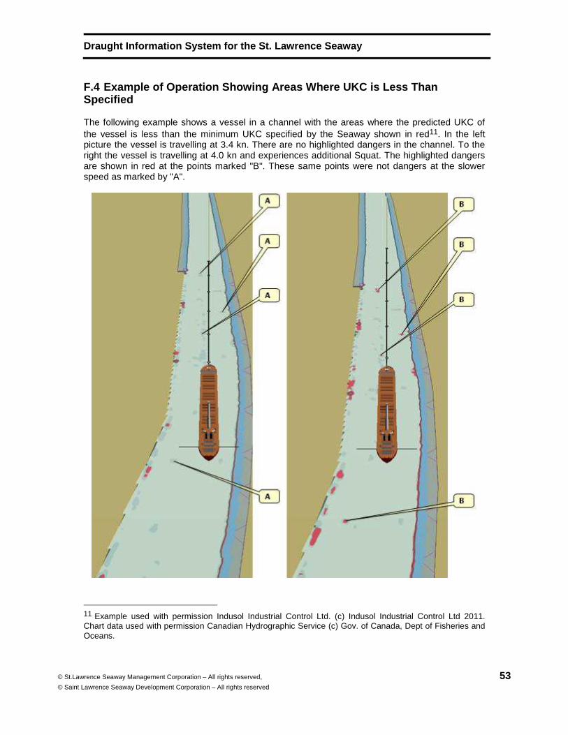
Draught Information System for the St. Lawrence Sea way
© St.Lawrence Seaway Management Corporation – All rights reserved,
© Saint Lawrence Seaway Development Corporation – All rights reserved 53
F.4 Example of Operation Showing Areas Where UKC is Less Than Specified
The following example shows a vessel in a channel with the areas where the predicted UKC of the vessel is less than the minimum UKC specified by the Seaway shown in red11. In the left picture the vessel is travelling at 3.4 kn. There are no highlighted dangers in the channel. To the right the vessel is travelling at 4.0 kn and experiences additional Squat. The highlighted dangers are shown in red at the points marked "B". These same points were not dangers at the slower speed as marked by "A".
11 Example used with permission Indusol Industrial Control Ltd. (c) Indusol Industrial Control Ltd 2011. Chart data used with permission Canadian Hydrographic Service (c) Gov. of Canada, Dept of Fisheries and Oceans.
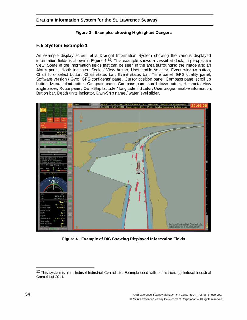
Draught Information System for the St. Lawrence Sea way
54 © St.Lawrence Seaway Management Corporation – All rights reserved,
© Saint Lawrence Seaway Development Corporation – All rights reserved
Figure 3 - Examples showing Highlighted Dangers
F.5 System Example 1
An example display screen of a Draught Information System showing the various displayed information fields is shown in Figure 4 12. This example shows a vessel at dock, in perspective view. Some of the information fields that can be seen in the area surrounding the image are: an Alarm panel, North indicator, Scale / View button, User profile selector, Event window button, Chart folio select button, Chart status bar, Event status bar, Time panel, GPS quality panel, Software version / Gyro, GPS confidents’ panel, Cursor position panel, Compass panel scroll up button, Menu select button, Compass panel, Compass panel scroll down button, Horizontal view angle slider, Route panel, Own-Ship latitude / longitude indicator, User programmable information, Button bar, Depth units indicator, Own-Ship name / water level slider.
Figure 4 - Example of DIS Showing Displayed Informa tion Fields
12 This system is from Indusol Industrial Control Ltd, Example used with permission. (c) Indusol Industrial Control Ltd 2011.
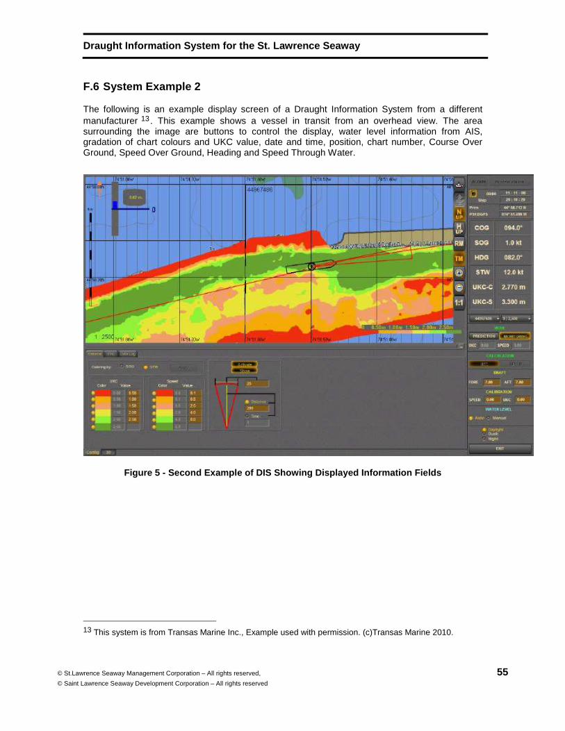
Draught Information System for the St. Lawrence Sea way
© St.Lawrence Seaway Management Corporation – All rights reserved,
© Saint Lawrence Seaway Development Corporation – All rights reserved 55
F.6 System Example 2
The following is an example display screen of a Draught Information System from a different manufacturer 13 . This example shows a vessel in transit from an overhead view. The area surrounding the image are buttons to control the display, water level information from AIS, gradation of chart colours and UKC value, date and time, position, chart number, Course Over Ground, Speed Over Ground, Heading and Speed Through Water.
Figure 5 - Second Example of DIS Showing Displayed Information Fields
13 This system is from Transas Marine Inc., Example used with permission. (c)Transas Marine 2010.

CD Draught Information System for the St. Lawrence Seaway
© St. Lawrence Seaway Management Corporation – All rights reserved,
© Saint Lawrence Seaway Development Corporation – All rights reserved 56
Bibliography
[1] Morse, B., Michaud, S., Siles, J., 2002, “Maximization of Ship Draft in the St. Lawrence Seaway; Volume 2: In-Depth Analysis of Squat and UKC”, TP 13888E, Université Laval for Transport Development Centre of Transport Canada and The St. Lawrence Seaway Management Corporation, Quebec, Canada
[2] International Standard ISO 80000-3:2006, Quantities and units -- Part 3: Space and time, International Organization for Standardization, Geneva, Switzerland.
[3] Le Système International d'Unités (SI), (The International System of Units (SI)), 8th Edition, Bureau International Poids et Mesures, 2006, Sèvres, France.
[4] IHO S-32, Hydrographic Dictionary, Fifth Edition, 1994, Monaco
[5] IHO S-52, Specifications for Chart Content and Display Aspects of ECDIS, Edition 6.0, March 2010, Monaco.
[6] ITU-R M.1371 (11/98), Technical characteristics for a universal shipborne automatic identification system using time division multiple access in the VHF maritime mobile band, International Telecommunications Union, Geneva, Switzerland.
[7] ISO/IEC/ITU Common Patent Policy, ISO, Geneva, Switzerland, April 2007
[8] Guidelines for Implementation of the Common Patent Policy for ITU-T/ITU-R/ISO/IEC, Geneva, Switzerland, March 2007
[9] International Hydrograph Organization, IHO ENC TEST DATA SETS, International Hydrographic Bureau, Monaco. 2008
[10] International Standard ISO 19123:2005, Geographic information - Coverage geometry and functions, Geneva, Switzerland.
[11] International Standard IEC 61162-2:1989, Maritime navigation and radiocommunication equipment and systems – Digital interfaces – Part 2: Single talker and multiple listeners, high-speed transmission
[12] NMEA 0183 – Version 2.30:1998, National marine electronics association (USA) – Standard for interfacing marine electronic navigational devices
[13] St. Lawrence Seaway Management Corporation, Seaway Handbook, 2010 Edition, Cornwall, Ontario, Canada