Embed Size (px)
Citation preview

Implementation of Orienteering Methods forAdvanced Autonomous Robot
Jaromir Konecny, and Michal Prauzek
Abstract—The autonomous robots are very popular researchfield. The scientist make effort to do autonomous robot, whichwill able to translate from start position to goal and there carryout mission. The missions are diverse. It can be simple missionsuch make a beep, or more complicated mission such detecttoxic gas or bomb disposal. This article proposes robot proto-type, which is intended for roboorienteering competition, whereenthusiasts try to reach several goals in as short time as possible.This article presents robot control system, implementation andhardware resources of robot prototype. The navigation strategyis also mentioned.
Index Terms—Autonomous robot, navigation, map design,AutoCAD extension, object oriented programing.
I. INTRODUCTION
THIS research is follow-up to previous research in theroboorienteering field. Autonomous robot for indoor use
shows the publication [1]. Another research [2] deals withexploratory vehicle for outdoor use. This research deals withoutdoor autonomous device such it was published e.g. in[10] [11]. This article proposes the concept of autonomousrobot, which is navigated by maps. The robot primary usesGPS localization system to establish the position in the map.It uses the maps, which are drawn in AutoCAD software.The map includes roads, walls, forests and another usefulinformations. The navigation counts with complex terrain,where it is much complicated recognize all obstacles andfind the optimal way to reach goal. The route planning usesDijkstra algorithm, which was published in [8] and [9]. Thenavigation concept especially proposes solution for orienta-tion in areas, where direct azimuth does not lead for the goal.The complex control application is written in C# languageand it runs Windows XP Embedded operating system and ittakes advantages of object orienting programing.
II. ROBOT HARDWARE RESOURCES
This section describes hardware construction of the robot.Robot chassis is constructed from aluminum profiles. Theseprofiles are fitted with wheels, motors and electronic sub-systems. Robot chassis is designed as a six-wheeled con-struction. The left front wheel is complementarily crossassociated with the left rear wheel and the front right wheel iscomplementary cross connected to the right rear. Left centerwheel and the right center wheel are controlled separately.The change of the robot direction is possible by differentspeeds or direction of left and right wheels rotation. Each
Manuscript received July 2nd, 2013; revised August 1st, 2013. Thiswork was supported by project SP2013/168, Methods of Acquisition andTransmission of Data in Distributed Systems of Student Grant System, VSB-TU Ostrava.
All authors are with the Department of Cybernetics and BiomedicalEngineering, VSB-Technical University of Ostrava, 17. listopadu 2172/15,70833 Ostrava, Czech Republic, Europe, e-mail: [email protected].
driven wheel has one engine Pololu1106 [4] (in czech).The motors are controlled by the driver Sabertooth 2X5.The heart of the control subsystem is Kontron pITX-SP 1.6GHz [5]. It is computer that runs Windows XP Embeddedoperating system. This device is connected to any of sensorsubsystems. These include ultrasonic sensor SRF08, opticalrangefinders GP2Y0A02. In addition, the robot has a 2Dlaser sensor HOKYUO URG04-LX [6]. The robot directioncan be detected by the electronic compass CMPS10. Robotalso includes front video camera Logitech. Absolute positionis determined by GPS module. Manual control is enabledby connecting a wireless gamepad. Two powerful Li-polbatteries are used for power supply. Both batteries usedvoltage 14.4 V and capacity 4 Ah and 5 Ah.
III. MAP DESIGN FOR THE ROBOT
This chapter describes the procedure for drawing mapsfor robot. Robot is able to work with maps, which mustbe provided by operator. Map data are in XML format andthey contains information about the environment in whichthe robot will move. The maps are also recorded informationabout possible trajectories which the robot can safely move.The vector graphics application is used to create map surface,which allows the conversion of the drawing to XML file issuitable for the robot. As software for the maps preparationis used AutoCAD 2012. AutoCAD 2012 is able to cooperatewith specialized GIS Software to professional maps creating.AutoCAD 2012 is also essentially an opened platform thatallows custom extensions that extend the functionality ofAutoCAD 2012. These extensions can be created either in theVisual LISP programming language, use the .NET libraries,which are then loaded by command netload. Connectionwith .NET provides full program control. The extension waswritten for making maps, which is capable directly generatemap background from the drawing opened in AutoCAD2012. Drawing must meet several conditions: Entity placedin the drawing must be in UTM coordinates. This is only apartial coordinates x and y. Zone and hemisphere are enteredin the Settings dialog.
Drawing is subdivided into different layers. The suitablemap for the robot has several layers. The most importantare the layers which constitute the safety trajectory linesnetwork. Safety trajectory segment provides the way therobot can move from the start point to the end point. Theeffort corresponds to the length of the line multiplied by aweight factor of the layer.
Trajectories are formed to three layers. The road, sidewalk,footpath. Obviously, the effort of movement along the roadis less than the effort of movement along the footpath. Theweight coefficients were selected: Road k = 1, sidewalkk = 2, footpath k = 3. Map data does not reflect a priori
Proceedings of the World Congress on Engineering and Computer Science 2013 Vol I WCECS 2013, 23-25 October, 2013, San Francisco, USA
ISBN: 978-988-19252-3-7 ISSN: 2078-0958 (Print); ISSN: 2078-0966 (Online)
WCECS 2013
terrain bumps, and therefore it is necessary to enter thismanually during the map creation. Unsurprisingly, the roaddown the hill for the robot will be less demanding than theway up the hill on the same segment. In order to take intoaccount the ascent and descent, it is possible to add a specialdimensions to the map. This dimensions modifies the effortform start point to end point.
Other layers in the map symbolize walls, forest, concretepillars, metal structures, etc. It is important to distinguishfrom other metal structures, because of the proximity ofmetal structures can affect the accuracy of the electroniccompass. The layer content is set in a special dialog thatis part of the extension of AutoCAD 2012. The data fromthose dialog are stored into the dictionary, which is partof the drawing. There is no need to carry another drawingfile containing those information. In addition, dictionary ishidden to a normal user and it can not be accidentally damageby the user. After setting those additional information it ispossible to process the map generation.
IV. CONTROL APPLICATION
This chapter describes an application that allows complexrobot control and full control over the hardware componentsof the robot. The application is written in C# language under.NET framework 2.0. Older version framework .NET 2.0 waschosen for compatibility with Windows Embedded operatingsystem. Advantage of this solution is that the developmentof application, including debugging and stepping can beperformed on a standard PC running Windows and then nochanges are required for the Windows Embedded operatingsystem device. The only problem may be the speed of theprogram. When deploying the application, it is necessary tothink about the fact that the target device does not have somuch hardware resources as a regular personal computer ornotebook.
A. Application structure
The application itself is divided into several parts. Fur-thermore, the application functionality is divided into severalthreads, which are mutually synchronized. The main threadis a application thread and graphical user environment. Theapplication starts only in system icons area, in order tothe final deployment forms and graphic components do notconsume unnecessary hardware resources. If it is desired,control the application forms can be shown any time byclicking onto mentioned icon.
The second thread is the guardian. It is the thread thathandles the connection of all critical hardware components.If the guardian determines that e.g. laser sensor does notcommunicate, it tries to reboot it and reconnect it. Classguardian also allows you to get comprehensive informationabout the state of hardware.
Other threads are carrying for the individual hardware.Each complex sensor has own thread serving function. Inparticular, I2C, laser sensor, GPS, camera, gamepad, motorunit are controlled by separate threads. There a chanceof some sensor failure during the movement of the robot.In this case failures only one appropriate thread. Anotherfunctionality of the robot is not compromised. In addition
guardian thread restart it and the sensor will likely runproperly again.
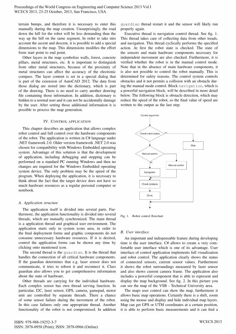
Executive thread is navigation control thread. See fig. 1.This thread takes care of collecting data from other treads,and navigation. This thread cyclically performs the specifiedaction. At first the robot state is checked. The state ofthe sensors and main hardware components necessary forindependent movement are also checked. Furthermore, it isverified whether the robot is in the manual control mode.Note that in the absence of main hardware components, itis also not possible to control the robot manually. This isdetermined for safety reasons. The control system controlsobstacles and it not permits a collision with an obstacle dur-ing the manual mode control. Block navigation, which isa powerful navigation block, will be described in more detailbelow. The following block is obstacle detection, which mayreduce the speed of the robot, so the final value of speed arewritten to the output as the last step.
Fig. 1. Robot control flowchart
B. User interface
An important and indispensable feature during developingtime is the user interface. C# allows to create a very com-fortable user interface which is one of its advantage. Userinterface of control application implements full visualizationand robot control. The application clearly shows the statusof connected sensors, current sensor values. Furthermoreit shows the robot surroundings measured by laser sensorand also shows current camera frame. The application alsoincludes a powerful component that is able to represent anddisplay the map background. See fig. 2. In this picture youcan see the map of the VSB - Technical University area.
The maps user control can show the map, furthermore itallows basic map operations. Certainly there is a shift, zoomusing the mouse and display and hide individual map layers.Map can get GPS or UTM coordinates at a certain position,it is able to perform basic measurements and it can find a
Proceedings of the World Congress on Engineering and Computer Science 2013 Vol I WCECS 2013, 23-25 October, 2013, San Francisco, USA
ISBN: 978-988-19252-3-7 ISSN: 2078-0958 (Print); ISSN: 2078-0966 (Online)
WCECS 2013

Fig. 2. Map representation in control application
suitable route from point A to point B. At the same time therobot is able to enter the target position. The user interfaceis shown fig. 3. The figure shows one of the application tab.On the top is the status panel with status icons. This panelis visible all the time. When any icon appears, it means theappropriate system does not work properly. On the rest ofthe screen is tab area. There are situated any other requiredcontrols. The first tab is the basic parameter tab whichincludes basic sensor information. The graphic representationof URG sensor, optical and ultrasonic sensors are shownon SRF and URG sensor area. The connection status areashows detailed information about connected subsystems.The engine status area shows load of the each motor. Thecontrol application includes several another tabs. Camera tabsprovides full camera control, process values shows the valuesof the sensors, map tab provides map control. The next tab isfeatures tab. It allows action stack and action queue control,goals control and manual action settings. The tab parametersallows set any constant and finally the log tab shows logmessages.
Fig. 3. Control application user interface
C. Object oriented approach to implementing navigation
To navigate the robot the navigation block is used, whichhas been already mentioned above. This block cyclicallyperforms actions, that are used to control the robot move-ment. Object-oriented approach is used for implementation.The action is generally implemented as an interface. Thisinterface contains generally defined methods and propertiesthat must implement each action. The most important of themare the method DoAction() and Terminated property.Method DoAction() is called cyclically, and it controlsthe robot. If the action is done Terminated property is setto True, and the navigation algorithm knows which actionhas to be performed. The advantage of this approach is ageneralization of the action and to implement new action isnot necessary to modify any executive navigation function.
V. ROBOT NAVIGATION
Now the navigation block will be described and strategyrobot navigation will be mentioned. The goal navigation issimilar to car navigation. It is calculated list of points to beachieved to reach the goal. The following paragraphs willdescribe the algorithm scheduling checkpoints and performa sequence of actions that will lead to the goal.
A. Route planing
The route planning will be briefly discussed. The robotmoves in the known environment, so it has a map. There arerecorded information about possible trajectories of movementin this map. The aim is to design a trajectory from pointA to point B. For finding the optimal trajectory Dijkstraalgorithm algorithm is used. This algorithm finds the bestroute according to the criteria. In this case, the criterionof segment weight. Weight is the product of the length ofthe segment and its coefficient of performance. See equation(1). In a sense, we can say that it is the shortest route. TheDijkstra algorithm is presented in a well arranged way inreference [9].
w = k ·√
(x1 − x2)2 + (y1 − y2)2 (1)
The base unit of the map is the vertex. Vertex is generalobject, which should be comparable. In this case the vertex isCartesian point. The another base object is connecting rod.This object involves start point, end point, weight start toend and end to start respectively. See equation (2). s is startpoint, e is end point, w1 is start to end weight and w2 isend to start weight. The input parameters for the Dijkstraalgorithm are start point, end point, and list of connectingrods. The list of connecting rods is extracted from the map.The output of Dijkstra algorithm is list of vertexes, whichheads to goal.
r = {[sx, sy], [ex, ey], w1, w2} (2)
Obtained list of vertexes corresponds with actions. Eachvertex from list is one partial goal, which should be reached.Thats is path-planning strategy.
Proceedings of the World Congress on Engineering and Computer Science 2013 Vol I WCECS 2013, 23-25 October, 2013, San Francisco, USA
ISBN: 978-988-19252-3-7 ISSN: 2078-0958 (Print); ISSN: 2078-0966 (Online)
WCECS 2013
B. Actions execution
The preceding paragraph described the principle of ob-taining the actions sequence that need to be done. Now,the principles will described how actions are performed.Scheduled actions are stored in the queue. See fig. 4. Thereare now stored actions A4 - A7 in the queue. Most recentactions will therefore perform last. If new action A8 isinserted, it is put in a queue behind action A7. The queue islarge enough and it does not overflow. A8 action will thus beadded at the end of the queue. On the other side of the queueare actions fetched and executed. Assume that the stack ofevents is now empty and there is no need for replace. In thiscase, the actions are sequentially fetched from the queue andexecuted.
Suppose that there is a requirement that is necessary toexecute the action A9, which was not planned and should beperformed first. Actions A3 in this case is stored to the stackand action A9 replaces the current event. Once complete,A9, the algorithm first looks into the stack. If not empty,instead of the queue it pick up the action from the stack.Thus it is possible to heap unplanned actions to the stack.Example of this is wrong robot direction. Suppose the queueplanned route. In the simplest case, the scheduled actions area sequence of checkpoints that must be achieved. Achievingone point will be done so that the robot will move alongthe azimuth direction of the checkpoint. However if desiredazimuth significantly different, it is necessary rotate robotfirst. This rotation is different action so it is necessary toreplace the operation and current action push into stack. Thenew action must be execute immediately, therefore it can notbe push at the end of the queue.
Fig. 4. Executing action scheme
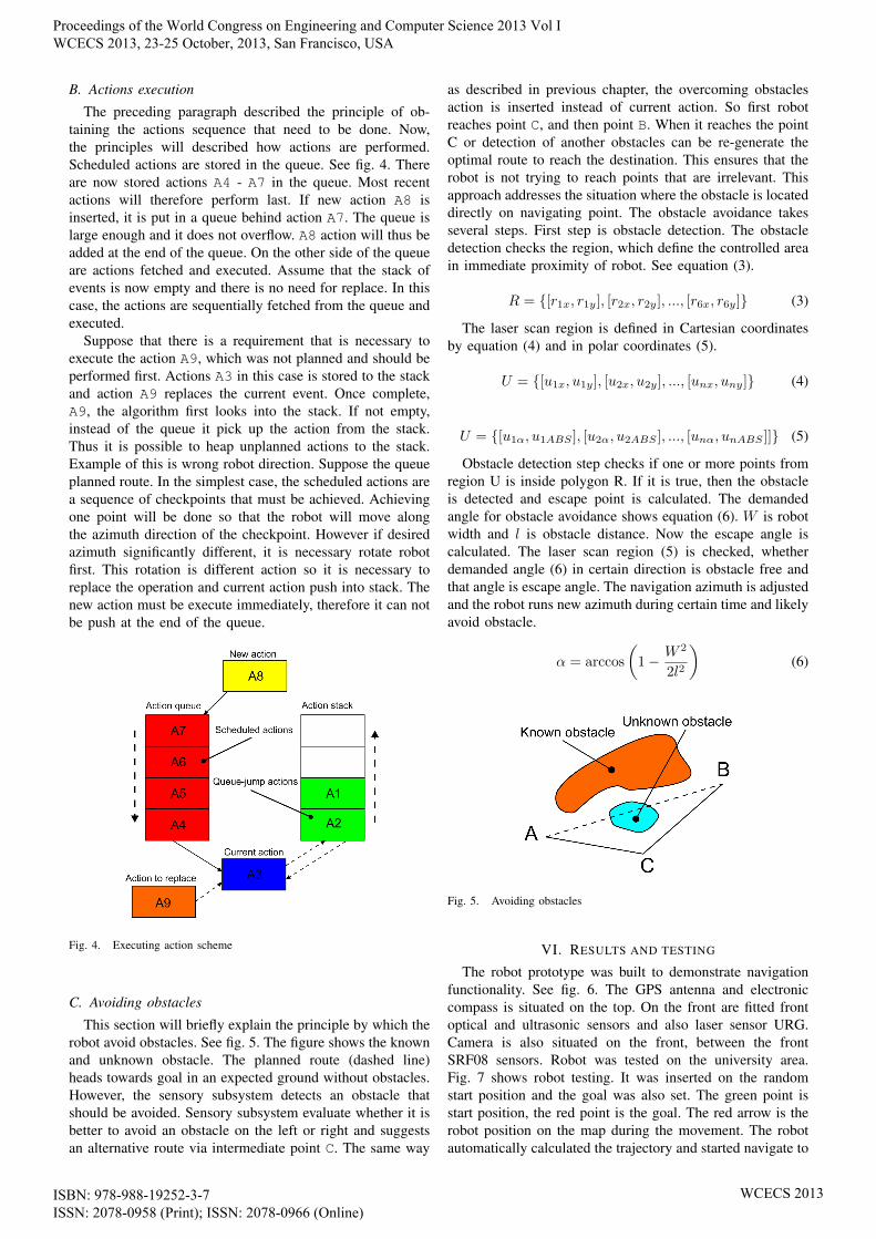
C. Avoiding obstacles
This section will briefly explain the principle by which therobot avoid obstacles. See fig. 5. The figure shows the knownand unknown obstacle. The planned route (dashed line)heads towards goal in an expected ground without obstacles.However, the sensory subsystem detects an obstacle thatshould be avoided. Sensory subsystem evaluate whether it isbetter to avoid an obstacle on the left or right and suggestsan alternative route via intermediate point C. The same way
as described in previous chapter, the overcoming obstaclesaction is inserted instead of current action. So first robotreaches point C, and then point B. When it reaches the pointC or detection of another obstacles can be re-generate theoptimal route to reach the destination. This ensures that therobot is not trying to reach points that are irrelevant. Thisapproach addresses the situation where the obstacle is locateddirectly on navigating point. The obstacle avoidance takesseveral steps. First step is obstacle detection. The obstacledetection checks the region, which define the controlled areain immediate proximity of robot. See equation (3).
R = {[r1x, r1y], [r2x, r2y], ..., [r6x, r6y]} (3)
The laser scan region is defined in Cartesian coordinatesby equation (4) and in polar coordinates (5).
U = {[u1x, u1y], [u2x, u2y], ..., [unx, uny]} (4)
U = {[u1α, u1ABS ], [u2α, u2ABS ], ..., [unα, unABS ]]} (5)
Obstacle detection step checks if one or more points fromregion U is inside polygon R. If it is true, then the obstacleis detected and escape point is calculated. The demandedangle for obstacle avoidance shows equation (6). W is robotwidth and l is obstacle distance. Now the escape angle iscalculated. The laser scan region (5) is checked, whetherdemanded angle (6) in certain direction is obstacle free andthat angle is escape angle. The navigation azimuth is adjustedand the robot runs new azimuth during certain time and likelyavoid obstacle.
α = arccos
(1− W 2
2l2
)(6)
Fig. 5. Avoiding obstacles
VI. RESULTS AND TESTING
The robot prototype was built to demonstrate navigationfunctionality. See fig. 6. The GPS antenna and electroniccompass is situated on the top. On the front are fitted frontoptical and ultrasonic sensors and also laser sensor URG.Camera is also situated on the front, between the frontSRF08 sensors. Robot was tested on the university area.Fig. 7 shows robot testing. It was inserted on the randomstart position and the goal was also set. The green point isstart position, the red point is the goal. The red arrow is therobot position on the map during the movement. The robotautomatically calculated the trajectory and started navigate to
Proceedings of the World Congress on Engineering and Computer Science 2013 Vol I WCECS 2013, 23-25 October, 2013, San Francisco, USA
ISBN: 978-988-19252-3-7 ISSN: 2078-0958 (Print); ISSN: 2078-0966 (Online)
WCECS 2013

goal immediately. Figure shows, that the robot is navigatedto each segment on the road towards goal. The violet curverepresents calculated trajectory.
Fig. 6. Robot Aegis
During the tests several issues appears. The robot was builtfor roboorienteering competition primary [3]. The area ofthe university has several differences instead of competitionarea. One of the issue is parked cars. Parked cars are higherthan robot sensor subsystem and therefore robot does notdetect it. Second issue are bollards. Bollard is instead ofcar to low to detect. When the robot meet low bollard, ittries to climb it. Not every time it is possible. In futurework we are expecting sensor subsystem modification. Likelywe adjust the ultrasonic and optic sensors to trace cars andbollards. Despite obstacle issues the robot is able to moveautomatically. When GPS position is available with sufficientprecision, the robot goes on the roads by the map and reachthe goals. When the robot has position with deviation, it stillexpect that it is on the road. In actual fact robot is nextto road and likely there are mentioned issues like parkedcars, bollard, trees or high amount of another obstacles. Thesituation is better when the bollard is higher or further it is awall. In this case the robot detect it and it adjust the azimuthand follows the wall.
Fig. 7. Testing in university area
One of the advantage of map concept is complex routeplanning. See fig. 8. The start point and the destination pointis relatively close. There is no suitable way to reach the goaldirect. There is forbidden area. It is not important way isthe area forbidden, there might be ravine, or hard terrain orsomething else. The basic impact is the robot choose anotherway to reach the goal, which is likely safer.
Fig. 8. Route calculation
VII. CONCLUSION
We were making the robot prototype with GPS navigationon the map and it was tested on the university area. Fornext year we will the research goes on and we will takepart the roboorienteering competition. The main advantageof map concept is the ability of calculate complex trajectory.As it is shown in fig. 8, the route to goal is much differentthan straight direction. Another advantage is knowledge ofobstacles, especially steel construction. Steel constructionmay affect the compass and GPS precision. In case the safetyroads in the map are created with respect to steel construc-tion, the robot do not move close. The main disadvantage ismentioned dependency on GPS signal. For the future workis expected, that we solve the issues with GPS signal. Forthe future work we will implement one of the known methodsuch as fuzzy logic [7].
REFERENCES
[1] J. Kotzian, J. Konecny, H. Prokop, T. Lippa, M. Kuruc, “Autonomousexplorative mobile robot navigation and construction,” in RoedunetInternational Conference (RoEduNet), 2010 9th , vol., no., pp.49,54,24-26 June 2010
[2] J. Konecny, M. Kelnar and M. Prauzek, “Advanced Waste Rock Explor-ing by Mobile Robot.” Applied Mechanics and Materials. 2013, 313-314, s. 913-917. DOI: 10.4028/www.scientific.net/AMM.313-314.913.
[3] Roboorienteering. Roboorienteering, 2013 URL:http://www.vosrk.cz/roboorienteering/
[4] Snail Instruments, 2013 [cit. 2013-07-02]. URL:http://www.snailshop.cz/
[5] News from Kontron.com. Kontron, 2013 [cit. 2013-07-02]. URL:http://emea.kontron.com/products/boards+and+mezzanines/embedded+sbc/pitx+25+sbc/pitxsp.html
[6] HOKUYO AUTOMATIC CO.,LTD.: Photoelectric switch, FA sensor,Parallel I/O, HMD/CMD, Laser distance sensor and for Robots, 2013[cit. 2013-07-02]. URL: http://www.hokuyo-aut.jp/
[7] Seraji, H.; Howard, A., ”Behavior-based robot navigation on chal-lenging terrain: A fuzzy logic approach,” Robotics and Automation,IEEE Transactions on , vol.18, no.3, pp.308,321, Jun 2002 doi:10.1109/TRA.2002.1019461
[8] Lixiao Guo; Qiang Yang; Wenjun Yan, ”Intelligent path planning forautomated guided vehicles system based on topological map,” Control,Systems & Industrial Informatics (ICCSII), 2012 IEEE Conference on ,vol., no., pp.69,74, 23-26 Sept. 2012 doi: 10.1109/CCSII.2012.6470476
[9] Huijuan Wang; Yuan Yu; Yuan, Q., ”Application of Dijkstra algorithmin robot path-planning,” Mechanic Automation and Control Engineer-ing (MACE), 2011 Second International Conference on , vol., no.,pp.1067,1069, 15-17 July 2011 doi: 10.1109/MACE.2011.5987118
[10] Kuhnert, K., ”Software architecture of the Autonomous Mobile Out-door Robot AMOR,” Intelligent Vehicles Symposium, 2008 IEEE , vol.,no., pp.889,894, 4-6 June 2008 doi: 10.1109/IVS.2008.4621234
[11] Ohno, K.; Tsubouchi, T.; Shigematsu, B.; Maeyama, S.; Yuta,S., ”Outdoor navigation of a mobile robot between buildingsbased on DGPS and odometry data fusion,” Robotics and Au-tomation, 2003. Proceedings. ICRA ’03. IEEE International Con-ference on , vol.2, no., pp.1978,1984 vol.2, 14-19 Sept. 2003 doi:10.1109/ROBOT.2003.1241884
Proceedings of the World Congress on Engineering and Computer Science 2013 Vol I WCECS 2013, 23-25 October, 2013, San Francisco, USA
ISBN: 978-988-19252-3-7 ISSN: 2078-0958 (Print); ISSN: 2078-0966 (Online)
WCECS 2013